1
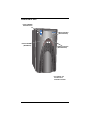
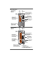
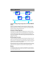
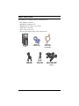
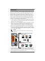
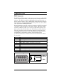
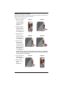
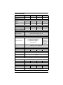
S2K UPS
USER MANUAL
Line-Interactive
350-1000 VA
230V
TABLE OF CONTENTS
IMPORTANT SAFETY INSTRUCTIONS . . . . . . . . . . . . . . . . . . . . . 1
INTRODUCTION & SYSTEM DESCRIPTION . . . . . . . . . . . . . . . . . 5
Front View of UPS . . . . . . . . . . . . . . . . . . . . . . . . . . . . . . . . . . . . 6
Rear View of UPS. . . . . . . . . . . . . . . . . . . . . . . . . . . . . . . . . . . . . 7
MAJOR COMPONENTS . . . . . . . . . . . . . . . . . . . . . . . . . . . . . . . 8
Transient Voltage Surge Suppression (TVSS) & EMI/RFI
Filters . . . . . . . . . . . . . . . . . . . . . . . . . . . . . . . . . . . . . . . . . . . . . . 8
Automatic Voltage Regulator . . . . . . . . . . . . . . . . . . . . . . . . . . . 8
Bi-Directional Converter . . . . . . . . . . . . . . . . . . . . . . . . . . . . . . . 8
Battery . . . . . . . . . . . . . . . . . . . . . . . . . . . . . . . . . . . . . . . . . . . . . 8
WHAT’S INCLUDED . . . . . . . . . . . . . . . . . . . . . . . . . . . . . . . . . 9
INSTALLATION. . . . . . . . . . . . . . . . . . . . . . . . . . . . . . . . . . . . 10
CONTROLS AND INDICATORS . . . . . . . . . . . . . . . . . . . . . . . . . 12
ON/OFF/Alarm Silence Button . . . . . . . . . . . . . . . . . . . . . . . . 12
Status Indicators: Mains, Battery, Fault . . . . . . . . . . . . . . . . . 13
Mains Indicator (Green/Amber) . . . . . . . . . . . . . . . . . . . . . . . . . . 13
Battery Indicator (Green/Amber) . . . . . . . . . . . . . . . . . . . . . . . . . 13
Fault Indicator (Red/Green) . . . . . . . . . . . . . . . . . . . . . . . . . . . . . 13
Location and Status of Indicators . . . . . . . . . . . . . . . . . . . . . . . . . 13
Transfer Voltage Selectors (DIP Switches) . . . . . . . . . . . . . . . 14
MODES OF OPERATION . . . . . . . . . . . . . . . . . . . . . . . . . . . . . 15
Normal Mode . . . . . . . . . . . . . . . . . . . . . . . . . . . . . . . . . . . . . . . 15
Buck/Boost Mode . . . . . . . . . . . . . . . . . . . . . . . . . . . . . . . . . . . . 15
Battery Mode . . . . . . . . . . . . . . . . . . . . . . . . . . . . . . . . . . . . . . . 16
COMMUNICATIONS . . . . . . . . . . . . . . . . . . . . . . . . . . . . . . . . 17
DB-9 Connector . . . . . . . . . . . . . . . . . . . . . . . . . . . . . . . . . . . . . 17
Remote Shutdown Via the DB-9 Connector . . . . . . . . . . . . . . . 18
Shutdown Via Pins 5 & 6 . . . . . . . . . . . . . . . . . . . . . . . . . . . . . . . . 18
Shutdown Via Pins 4 & 5 . . . . . . . . . . . . . . . . . . . . . . . . . . . . . . . . 18
USB Interface Port. . . . . . . . . . . . . . . . . . . . . . . . . . . . . . . . . . . 18
Data Line Protection Connectors . . . . . . . . . . . . . . . . . . . . . . . 18
i
MAINTENANCE . . . . . . . . . . . . . . . . . . . . . . . . . . . . . . . . . . . 19
Cleaning the UPS. . . . . . . . . . . . . . . . . . . . . . . . . . . . . . . . . . . . 19
Maintaining Batteries . . . . . . . . . . . . . . . . . . . . . . . . . . . . . . . . 19
Battery Replacement . . . . . . . . . . . . . . . . . . . . . . . . . . . . . . . . . 19
Battery Replacement Procedure . . . . . . . . . . . . . . . . . . . . . . . . . . 20
TROUBLESHOOTING . . . . . . . . . . . . . . . . . . . . . . . . . . . . . . . 21
Guide to Status Indicators. . . . . . . . . . . . . . . . . . . . . . . . . . . . . 21
Troubleshooting Chart . . . . . . . . . . . . . . . . . . . . . . . . . . . . . . . . 22
SPECIFICATIONS . . . . . . . . . . . . . . . . . . . . . . . . . . . . . . . . . 23
Battery Run Times. . . . . . . . . . . . . . . . . . . . . . . . . . . . . . . . . . . 24
Product Warranty Registration. . . . . . . . . . . . . . . . . . . . . . . . . 25
ii
IMPORTANT SAFETY INSTRUCTIONS
SAVE THESE INSTRUCTIONS
This manual contains important safety instructions that should be followed during the installation and maintenance of the Uninterruptible
Power System (UPS) and its batteries. Please read this manual thoroughly before attempting to install or operate this UPS.
Read all safety, installation, and operating instructions before operating the UPS. Adhere to all warnings on the unit and in this manual.
Follow all operating and user instructions.
This equipment is designed for Commercial, Industrial or Residential
use. Sola/Hevi-Duty neither recommends nor knowingly sells this
product for use in life support applications or with other designated
critical devices.
This equipment can be installed and operated by individuals without
previous training.
!
WARNING
SAFETY PRECAUTIONS
• There are no user-serviceable parts inside this UPS except
the internal battery pack. Refer all UPS service to qualified service personnel. Do not attempt to service this product yourself.
• Output receptacles on the UPS are electrically live if the
UPS is switched on, even if the UPS is not plugged into a
Mains supply. The ON/OFF button on the UPS does not
electrically isolate the internal parts. Some components
are live even when Mains power is disconnected. To isolate
the UPS, switch off the UPS first, then unplug it from the
Mains.
• Opening or removing the cover may expose you to lethal
voltages within this unit even when it is apparently not
operating and the input wiring is disconnected from the
electrical source.
• Observe all CAUTION and WARNING statements in this
manual and on the unit. Failure to do so may result in
serious injury or death.
• Never work alone.
1
!
!
WARNING
ELECTRICAL PRECAUTIONS
• This UPS should not be supplied from electrical power systems of the “IT” (Impedance á Terre) type (IEC 364 - Electrical Installation of Buildings).
• The UPS must be earthed/grounded at all times during
operation. Connect only to a mains supply socket outlet
with an earth/ground connection.
CAUTION
Although your UPS has been designed and manufactured to
assure personal safety, improper use may result in electrical
shock or fire. To ensure safety, please observe the following
rules:
• Turn off and unplug your UPS before cleaning. Do not use
liquid or aerosol cleaners. A dry cloth is recommended to
remove dust from the surface of your UPS.
• Do not install or operate your UPS in or near water.
• Do not place your UPS on an unstable cart, stand or table.
• Do not place your UPS in direct sunlight or near heat
emitting sources.
• Never block or insert any objects into the ventilation holes
or other openings of the UPS. Keep all vents free of dust
accumulation that could restrict airflow.
• Do not place the UPS power cord in any area where it may
be damaged by heavy objects.
• Placing magnetic storage on the top of the UPS may result
in data corruption.
2
!
!
CAUTION
BATTERY HANDLING PRECAUTIONS
Servicing of batteries should be performed or supervised by
personnel knowledgeable of batteries and required
precautions. Keep unauthorized personnel away from the
batteries.
A battery can present a risk of electrical shock and high
short-circuit current. The following precautions should be
observed when working on batteries:
• Remove watches, rings, and other metal objects.
• Use tools with insulated handles.
• Do not dispose battery or batteries in a fire. The battery
may explode.
• Do not open or mutilate the battery or batteries. Released
electrolyte is harmful to skin and eyes. It may be toxic.
• When replacing the battery, use same number and type of
battery as the suitable recommended type of battery listed
in specification table in back of this manual.
• Handle, transport and recycle batteries in accordance with
local regulations.
WARNING
If your UPS demonstrates any of the following conditions,
turn off and unplug your UPS from the outlet and contact
your local distributor, Sola/Hevi-Duty representative, or
Sola/Hevi-Duty Technical Services.
• The power cord is damaged.
• Liquid has been spilled on the UPS.
• The circuit breaker or fuse opens frequently.
• The UPS does not operate in accordance with the user
manual.
3
Electromagnetic Compatibility—The Sola S2K series complies
with the requirements of the EMC Directive 89/336/EEC and the published technical standards. Continued compliance requires installation in accordance with these instructions and use of Sola/Hevi-Duty
approved accessories only.
Environmental—Operate the UPS in an indoor environment only in
an ambient temperature range of 0°C to 40°C (32°F to 104°F). Install
in a clean environment, free from conductive contaminates, moisture,
flammable liquids, gases, or corrosive substances.
Provided are a MultiLink cable and a USB cable for connection to a
computer. Do not use the MultiLink cable for other applications. Store
in a safe place if not required at this time.
When using the communication features on this UPS, ensure the
cabling connected to the DB-9 or UPS communications ports are kept
separated from the power leads to the UPS input and output.
4
INTRODUCTION & SYSTEM DESCRIPTION
Congratulations on your choice of the Sola S2K series Uninterruptible
Power System (UPS). It provides filtered AC power to sensitive electronic equipment and other critical loads.
The S2K unit is a line-interactive UPS designed for an office environment. It provides perfect power protection for PCs, point-of-sale systems, network and similar electronic equipment. It offers a
configurable input voltage window allowing you to precisely match
your equipment’s input power. Three communications options are
available: serial connection, contact closure and USB. The S2K unit is
available in four (4) sizes: 350, 500, 650 and 1000VA at 120 VAC and
230 VAC.
Sola S2K models are available for 120 VAC and 230 VAC supply voltages and loads. Please verify that this model matches your AC Mains
and load voltage requirements.
5
Front View of UPS
Power ON/OFF/
Alarm Silence*
Mains Indicator*
(Green/Amber)
Fault Indicator*
(Red/Green)
Battery Indicator*
(Green/Amber)
* For details, see
Controls and
Indicators section
6
Rear View of UPS
350&500VA
Models
DIP
switches**
USB
port***
Data Line Protection
Connectors (2)***
DB-9
port***
Phone/Fax/DSL/Internet/
Modem devices
Black output
receptacles (2)*
Orange output
receptacles*
Surge protection
only
Battery backup +
surge protection
AC
input
Input circuit
protector
Battery cover plate
(on rear of 350 &
500VA models)
650 &1000 VA
Models
DIP
switches**
USB
port***
DB-9
port***
Data Line Protection
Connectors (2)***
Orange output
receptacles*
Phone/Fax/DSL/Internet/
Modem devices
Battery backup +
surge protection
Black output
receptacles (2)*
Surge protection
only
NOTE: Bottom
two receptacles
on 1000VA
models only
Input circuit
protector
AC
input
Battery cover plate
(bottom of unit for
650 & 1000VA models)
For details, see:
* Installation section
** Controls and Indicators section
*** Communications section
7
MAJOR COMPONENTS
Input
L
TVSS &
EMI/RFI
Filters
Automatic
Voltage
Regulator
Output
L
Bi-Directional
Converter
Battery
N
N
G
G
Transient Voltage Surge Suppression (TVSS) & EMI/RFI
Filters
These UPS components provide surge protection and filter electromagnetic interference (EMI) and radio frequency interference (RFI).
They minimize surges or interference present in the mains line and
keep the sensitive equipment protected.
Automatic Voltage Regulator
The Automatic Voltage Regulator (AVR) protects connected equipment from power spikes and other abnormalities by raising an undervoltage (boost) and lowering an overvoltage (buck) as needed. This
keeps the UPS output voltage within the connected equipment’s tolerance and accommodates wide mains voltage fluctuations without utilizing the batteries.
Bi-Directional Converter
In normal operation, the Bi-Directional Converter changes mains AC
power into regulated DC power to “float charge” the battery system.
This converter is continuously charging the battery whenever the UPS
is plugged into a power outlet and mains power is within acceptable
limits—even if the UPS is turned OFF.
When mains power fails, the Bi-Directional Converter draws energy
from the battery and inverts it into a regulated stepped sinewave supplying power for equipment connected to the orange receptacles.
Battery
The S2K unit utilizes valve-regulated, nonspillable, lead acid batteries. To optimize battery life, operate the UPS in an ambient temperature of 20°-25°C (68°-77°F).
8
WHAT’S INCLUDED
The S2K unit is shipped with the following items:
• Sola S2K user manual
• MultiLink™ software CD
• MultiLink serial cable, 3.0m (10 ft.)
• USB cable, 1.8m (6 ft.)
• RJ-11 cord, 2.1m (7 ft.)
• Two (2) 10A output power cords, 2.0m (6.6 ft.)
Sola S2K
Unit
USB cable
1.8m (6 ft.)
MultiLink
software CD
RJ-11 cord
2.1m (7 ft.)
9
MultiLink
serial cable
3.0m (10 ft.)
Two (2) 10A output
power cords, 2.0m
(6.6 ft.)
INSTALLATION
This UPS is designed for data processing equipment. Maximum load
must not exceed that shown on the UPS rating label. Do not connect
equipment that could overload the UPS or draw half-wave current
from the UPS, for example: electric drills, vacuum cleaners, laser
printers or hair dryers. Your total load earth leakage current must not
exceed 3.5 mA. Most data processing equipment meets this requirement if you use no more than two pieces of equipment. If uncertain
about your load, consult your local distributor, Sola/Hevi-Duty representative, or Sola/Hevi-Duty Technical Services.
1. Visually inspect the UPS for freight damage. Report damage to the
carrier and your local distributor, Sola/Hevi-Duty representative, or
Sola/Hevi-Duty Technical Services.
2. Decide where to place the S2K unit. Find a location that is near an
easily accessible mains outlet. Install the UPS indoors in a controlled environment, where it cannot be accidentally turned off.
Place it in an area of unrestricted airflow around the unit, away
from water, flammable liquids, gases, corrosives, and conductive
contaminants. Maintain a minimum clearance of 100mm (4 inches)
on each side of the UPS. Maintain an ambient temperature range of
0°C to 40°C (32°F to 104°F).
NOTE
UPS operation in temperatures above 25°C (77°F) reduces
battery life.
Plug computers, monitors & network hubs
into orange receptacles
Plug this type of equipment into black
receptacles ONLY
Inkjet
printer
Scanner
Fax
machine
3. The Sola S2K 230 VAC models are not supplied with an input power
lead for connection to the mains supply. Additional input/output
leads can be obtained from your dealer. The input power cord must
have a minimal cross-sectional area of 1mm2.
10
4. Shut down the load equipment and turn off the mains supply.
Unplug the load equipment’s power input cable from the mains supply socket and plug it into the UPS input socket. Plug the power
input cable into the mains supply socket.
Connect the supplied IEC-320-C14 output power cable between the
load equipment input socket and one of the UPS AC output sockets.
Connect all load equipment to the UPS in this manner.
5. Plug any computers and monitors into the orange battery backed up
receptacles.
Other office machines that do not exceed the capacity of the UPS—inkjet printers, scanners and fax machines—may be plugged into either of
the two (2) black receptacles, which provide surge protection only.
6. Connect Phone/Fax/DSL/Internet/Modem devices to data line connectors.
Serial port for MultiLink cable connection
7. Press and release the ON/OFF/Alarm Silence button to turn on the
UPS. The UPS will beep and the Mains Indicator will illuminate (green).
8. Turn on connected equipment.
9. Communication options (see Communications section for details):
Option 1—Serial Communications
Serial communications provides parametric data, for example,
input voltage and battery voltage.
a. Connect MultiLink serial cable included with the UPS to communications port.
b. Install the MultiLink software—the software and installation
instructions, as well as the user manual, are on the CD included
in the Sola S2K package.
Option 2—Contact Closure Communications
Contact Closure communications provides on-battery and low-battery signals for orderly shutdown.
a. Refer to the MultiLink user manual for instructions on making
your own contact closure cable.
b. Install the MultiLink software—the software and installation
instructions, as well as the user manual, are on the CD included
in the Sola S2K package.
Option 3—USB Communications
a. Connect USB cable provided with the UPS to the USB ports on the
S2K and your computer. The S2K will work automatically with your
built-in power management software on Windows XP and 2000 and
Mac OS 10.2 or later (see USB Interface Port section for details).
11
CONTROLS AND INDICATORS
ON/OFF/Alarm Silence Button
This button controls output power to the
connected load and has three functions:
• ON
• OFF
• Alarm Silence
ON/OFF/Alarm Silence
ON
When the UPS is off, pressing and releasing the main ON/
OFF button will start the UPS, and an audible alarm sounds
briefly. The UPS is capable of starting on battery (battery
start).
OFF
When the UPS is on (in either Normal or Battery mode),
pressing the main ON/OFF button for more than
two (2) seconds will shut down the UPS. An audible alarm
sounds briefly.
Alarm When a UPS alarm is active, pressing and releasing the
Silence main ON/OFF button will silence the active audible alarm,
whether mains power is present or not. Once the alarm
silence function has been activated, all active audible
alarms—except for low battery, overload, or over-temperature conditions—will remain silenced until a new alarm condition is detected.
NOTE
Do not hold ON/OFF button down for more than 2 seconds
or the UPS will shut down.
12
Status Indicators: Mains, Battery, Fault
There are three (3) status indicators on the front of the UPS (Mains,
Battery and Fault), as shown in the diagram below. Each indicator
illuminates to specify the status of the UPS (see Troubleshooting
section for details).
Mains Indicator (Green/Amber)
The Mains Indicator illuminates when the UPS is operating and supplying power to connected loads: green indicates Normal mode, amber
denotes Buck/Boost mode.
Battery Indicator (Green/Amber)
The Battery Indicator illuminates to indicate the UPS is operating on
battery (green) or to signify a battery warning (amber).
Fault Indicator (Red/Green)
The Fault Indicator illuminates when the UPS detects a problem: red
for an internal UPS fault, green for overload and over-temperature
conditions.
Location and Status of Indicators
Mains Indicator
Green: Normal operation
Amber: Buck/Boost mode
Fault Indicator
Green: Overload/Over temperature
Red:
UPS fault
Battery Indicator
Green: On battery
Amber: Battery warning
NOTE
See Troubleshooting section for details.
13
Transfer Voltage Selectors (DIP Switches)
DIP Switches
Rear of UPS
The two-position DIP switch control on the rear panel, shown above,
allows the operator to select the mains transfer voltage at which the
UPS will switch to battery power. DIP switch positions for each voltage setting are as follows:
DIP switch settings
Left
!
!
Right
Nominal Mains
Input Range Setting
230VAC
163 - 282VAC (default)
↑ Up
↑ Up
↑ Up
↓ Down
220VAC
155 - 270VAC
↓ Down
↑ Up
240VAC
171 - 291VAC
↓ Down
↓ Down
230VAC
163 - 282VAC
CAUTION
Never change the voltage settings while the UPS is ON and
powering connected loads. Change DIP switches only when
the UPS is OFF.
CAUTION
To ensure protection of the connected equipment, the DIP
switch settings should match the nominal mains input
voltage. DIP switch settings not matching the nominal
mains could potentially damage connected equipment.
14
MODES OF OPERATION
Normal Mode
During Normal mode operation, the S2K unit supplies conditioned,
computer-grade power to the connected equipment: mains power
passes through the TVSS circuitry and the EMI/RFI filters and then
through the Bi-Directional Converter to connected equipment.
When the UPS is in Normal mode, the Mains Indicator illuminates
green.
Mains Indicator (Green)
The S2K unit continuously monitors the batteries to maintain them in
a fully charged state. The battery charger operates whenever AC
power is present, even if the UPS is switched off. By default, the UPS
is set to perform an automatic battery test after it has been operating
continuously for two (2) weeks. The interval at which the UPS will
perform a battery test can be configured via MultiLink.
Buck/Boost Mode
The Automatic Voltage Regulator (AVR) circuitry compensates for
fluctuations in mains power, such as voltage surges and sags. When
the S2K unit detects an abnormality, it raises the undervoltage
(boost) or lowers the overvoltage (buck) as needed. The AVR operates
automatically and maintains the output voltage to the connected critical equipment, without utilizing the batteries.
When the UPS is in Buck/Boost mode, the Mains Indicator illuminates amber.
Mains Indicator (Amber)
15
Battery Mode
The UPS switches to Battery mode in the event of an extreme voltage/
frequency condition or complete mains failure. The battery system
supplies power through the Bi-Directional Converter to generate
power for connected equipment.
When the UPS is in Battery mode, the Battery Indicator illuminates
green and an alarm sounds every 10 seconds.
Battery Indicator (Green)
When a low battery condition occurs, the Battery Indicator changes to
flashing amber and the alarm sounds every half-second. Low battery
warning is defaulted to two (2) minutes but can be configured via MultiLink. For more information, refer to Troubleshooting section.
Battery Indicator (flashing Amber)
!
CAUTION
Turning off the UPS while in either Normal mode or Battery
mode will result in the loss of output power.
NOTE
Once mains power is restored, the UPS resumes normal
operation. At this time, the battery charger begins recharging
the battery. The UPS is capable of OFF-State charging, i.e.,
with mains power, the UPS will charge the batteries as long
as it is plugged in.
16
COMMUNICATIONS
DB-9 Connector
The UPS has a DB-9 (9 pin female) connector on the rear to allow UPS
status communications with a computer system running MultiLink™
software. The DB-9 is capable of supplying serial communication, on
battery and low battery signals. MultiLink, UPS monitoring and shutdown software, is shipped with the UPS, along with a 3m (10 ft.) DB-9
cable required for running MultiLink.
When MultiLink is installed on the host computer, the UPS can signal
“on battery” and “low battery” using opto-couplers. When the UPS is
operating in Battery mode, it can receive a signal from the host computer system that will shut down the UPS (after gracefully shutting
down the operating system on the host computer system) when the
remaining battery run time is low. The timing of the signal depends
on MultiLink’s configuration settings. This shutdown signal
(5-12VDC) must have a duration of at least 2 seconds for the UPS to
be shut down.
DB-9 Pin
Assignment Description
1
Low Battery (open collector)
2
UPS TxD (typical RS-232 levels)
3
UPS RxD (typical RS-232 levels)
4
Battery Mode Shutdown (5-12VDC, 10-24 mA max)
5
Common
6
Any Mode Shutdown (short to Pin 5)
7
Low Battery (open emitter)
8
Mains Fail (open emitter)
9
Mains Fail (open collector)
DB-9 Pin Assignment
6
1
7
2
8
3
Collector to Emitter*
(+) Open
Collector
9
4
(-) Open
Emitter
5
* Maximum voltage and current on Pins 1, 7, 8, and 9 is 55VDC; 10.0 mA.
17
Remote Shutdown Via the DB-9 Connector
The S2K unit can be shut down remotely by shorting Pins 5 and 6 or
via Pins 4 and 5 of the DB-9 connector.
Shutdown Via Pins 5 & 6
When Pin 6 is shorted to Pin 5, the UPS output is shut off regardless
of what mode the UPS is operating in. The UPS cannot be started as
long as the pins are shorted. When the short is removed, the UPS output can be enabled by pressing the ON/OFF/Alarm Silence button.
Shutdown Via Pins 4 & 5
While the UPS is operating on battery (with no battery test in
progress), a 5-12VDC signal for 2 seconds or longer is required to signal a shutdown. Signals for less than 2 seconds are ignored.
After Pin 4 receives the shutdown signal, a 2-minute shutdown timer
inside the UPS begins a countdown. The timer cannot be stopped. If
mains power returns during the 2-minute timer countdown, the shutdown timer continues until the end of 2 minutes and then the UPS
turns off.
By default, autorestart is enabled so the UPS will restart after
10 seconds. If autorestart is disabled via MultiLink software, the UPS
remains off until a manual restart.
USB Interface Port
The S2K unit has a USB interface port for communication that will
work with most power management software and provide UPS status and management of the automatic orderly shutdown of the computer. The S2K’s USB communications meets HID standard,
version 1.11
Data Line Protection Connectors
Data line (IN & OUT) connectors are located on the rear of the UPS
and provide transient voltage surge suppression (TVSS) for Phone/
Fax/DSL/Internet/Modem devices.
18
MAINTENANCE
The Sola S2K UPS requires very little maintenance. Follow these
practices to prevent problems.
Cleaning the UPS
The following will help ensure trouble-free operation for years:
• Vacuum dust from the ventilation intake occasionally.
• Wipe the cover periodically with a dry cloth.
Maintaining Batteries
The batteries are valve-regulated, nonspillable, lead acid and must be
kept charged to retain their design life. The UPS continuously charges
the batteries when connected to the mains supply, even while the UPS
is switched off.
When storing the UPS, it is recommended to plug in the UPS for at
least 24 hours every four to six months to ensure full recharge of the
batteries.
Battery Replacement
!
CAUTION
A battery can present a risk of electrical shock and high
short circuit current. The following precautions should be
observed before replacing the batteries:
• Remove rings, watches, and other metal objects.
• Do not lay tools or other metal objects on top of the batteries.
• If the battery replacement kit is damaged in any way or
shows signs of leakage, contact your local distributor or
Sola/Hevi-Duty representative immediately.
• Do not dispose of batteries in a fire. The batteries may
explode.
• Dispose of old batteries according to local codes.
This UPS is equipped with internal “hot swappable” batteries that the
user can replace without shutting down the UPS or connected loads.
NOTE
Caution should be exercised when replacing the batteries
because the load is unprotected from disturbances and power
outages during this procedure.
19
Battery Replacement Procedure
Replacement requires removing the battery cover plate on the back or
bottom of the UPS. No tools are needed.
To replace the batteries:
1. Remove the battery cover plate
on the back/bottom of the UPS
(Figure 1).
Figure 1
Figure 2
Figure 3
Figure 4
2. Pull the white
tabs towards you
to remove the
battery from the
UPS (Figure 2).
3. Disconnect the
insulated connectors from the
battery terminals (Figure 3).
4. Insert a new
battery pack,
and push the
connectors onto
the battery terminals (black to
black & red to
red) (Figure 4).
NOTE: There may be a small spark at the battery terminals
when reconnecting the connectors. This is normal and will
not harm you or the UPS.
5. Push the battery
pack into the
UPS (Figure 5).
Figure 5
6. Reattach the
battery cover
plate
(Figure 6).
20
Figure 6
TROUBLESHOOTING
The information below indicates various symptoms a user may
encounter in the event the S2K unit experiences a problem. Use this
information to determine whether external factors caused the problem. See Troubleshooting Chart for suggested remedy.
1. The Fault indicator illuminates, indicating the
Mains
UPS detected a problem.
Indicator
Fault
Battery 2. An alarm sounds, alerting that the UPS
requires attention. The alarm can be silenced
Indicator Indicator
except for low battery, overload warning and
over-temperature warning conditions.
3. Mains and/or Battery indicators may be illuminated as a diagnostic aid to the operator, as
shown below:
Guide to Status Indicators
Fault
Indicator
Mains
Indicator
Green
ON
—
—
—
—
—
Amber
ON
Green
ON
—
—
—
Battery
Indicator
—
—
—
Green
Flashing
Green
Flashing
Green
ON
Green
ON
Green
ON
Red
Flashing
Red
ON
Green
ON
—
—
—
Green
ON
—
—
—
—
Green
ON
—
—
—
Diagnosis/
Audible Alarm
Normal operation with mains power
present; no beep.
Green UPS is operating on battery; beep every
ON 10 seconds.
Green
ON Battery test has been initiated; no beep.
UPS is operating in Buck/Boost mode;
no beep.
Amber Battery needs to be replaced; long beep
Flashing every minute.
Amber Low battery warning; beep every halfFlashing second.
Overload warning, load is >100%; beep
every half-second.
Overload shutdown, load exceeds UPS
capacity (110%); continuous beep.
Over temperature (overtemp) warning;
beep every 5 seconds (Normal mode).
Green Over temperature (overtemp) warning;
ON beep every 5 seconds (Battery mode).
Over temperature (overtemp) shutdown;
long beep every 5 seconds.
UPS is on, fault warning; continuous
beep.
UPS has failed & shut down; continuous
beep.
21
Troubleshooting Chart
If the UPS fails to operate properly, turn off the unit and repeat the
steps in the Installation section of this manual. If the problem persists, refer to the chart below:
Problem
UPS
will
not
start
UPS starts
on battery,
but will
not switch
to AC
Cause
Overload/
Short circuit
Check the circuit protector on the rear of
the UPS. If it is tripped, reset it and restart
the UPS.
For further help, call your local distributor,
Sola/Hevi-Duty representative, or Sola/
Hevi-Duty Technical Services.
Battery disconnected
or is completely
discharged
Check for proper connection of battery or
batteries.
UPS not plugged in
Plug in the power cord securely.
Circuit protector
tripped
Reset the circuit protector and restart the
UPS.
Power not available
at mains receptacle
Have the mains checked by a qualified
electrician.
Input voltage
below threshold
Wait until the voltage rises to an
appropriate level or have the mains
checked by a qualified electrician.
AC overvoltage
Wait until voltage lowers to an
appropriate level or have the mains
checked by a qualified electrician.
Overload/
Short circuit
UPS
shuts
down,
Fault
Indicator
Lit
UPS not
providing
expected
back-up
time
Solution
Internal UPS fault
Check the circuit protector on the rear of
the UPS. If it is tripped, reset it and restart
the UPS.
If the problem persists, disconnect some
of the equipment from your UPS—the
total wattage of your equipment must not
exceed the capacity of the UPS.
For further help, call your local distributor,
Sola/Hevi-Duty representative, or Sola/
Hevi-Duty Technical Services.
High temp shutdown
Make sure that the UPS is operating in a
0°C to 40°C (32°F to 104°F) environment
and that it has adequate ventilation.
MultiLink shutdown
Consult the MultiLink user manual or
contact your LAN administrator.
Overload
Reduce load.
Battery not charged
due to a recent outage
Recharge battery.
Battery needs to be
replaced
Replace battery.
22
SPECIFICATIONS
Model Number
S2K350-5
Power Rating VA/W
S2K500-5
S2K650-5
S2K1000-5
350VA/210W 500VA/300W 650VA/390W 1000VA/600W
DIMENSIONS: mm (in.)
116x196x222 116x196x222 116x358x222
Unit
WxDxH
Shipping
WxDxH
(4.6x7.7x8.7)
(4.6x7.7x8.7)
(4.6x14.1x8.7)
116x358x222
(4.6x14.1x8.7)
196x310x293 196x310x293 242x500x316 242x500x316
(7.7x12.2x11.5) (7.7x12.2x11.5) (9.5x19.7x12.4) (9.5x19.7x12.4)
WEIGHT: kg (lbs)
Unit
7.0 (15.4)
7.4 (16.3)
9.1 (20.1)
13.2 (19.1)
Shipping
8.2 (18.0)
8.5 (18.7)
11.2 (24.7)
15.3 (33.7)
INPUT AC PARAMETERS
Surge Protection
660J
Voltage Range Without
Battery Operation
155VAC - 291VAC, DIP switch selectable
(see DIP switch settings on page 14)
Frequency Range
46.5 - 63.5 Hz (±0.1 Hz)
OUTPUT AC PARAMETERS
Output Receptacles
(4) IEC-320-C13 (orange)
Battery backup + surge protection;
(2) IEC-320-C13 (black)
Surge protection
(6) IEC-320-C13
(orange) Battery
backup + surge
protection;
(2) IEC-320-C13
(black) Surge
protection
Output Power Cables
2m (6.6 ft.) detached IEC-320-C14
(Wire Type: 1mm2, H05W-F 3G)
Voltage (Normal mode)
Nominal (220, 230, 240VAC) ±10%
Voltage (Battery mode)
Output Current
230VAC ±8%
1.5 A
2.1 A
Waveform (Battery mode)
2.8 A
4.3 A
Stepped Sinewave
Frequency
50 Hz or 60 Hz; auto sensing
Overload Warning
(Normal & Battery modes)
>100%
Overload Shutdown
>110%
BATTERY PARAMETERS
Type
Valve-regulated, nonspillable, lead acid
QuantityxVoltagexRating (1)x12Vx7Ah (1)x12Vx9Ah (1)x12Vx9Ah (2)x12Vx7.5Ah
Transfer Time
4 - 6 ms typical
Backup Time
At 25°C (77°F), resistive loading, with fully charged batteries:
Full Load
8 minutes
Half Load
22 minutes
Recharge Time
7 minutes
5 minutes
5 minutes
21 minutes
15 minutes
16 minutes
6 hours to 90% of rated capacity,
after full discharge into a resistive load
23
ENVIRONMENTAL
Operating Temperature
0°C to +40°C
(+32°F to + 104°F)
Storage Temperature
-15°C to +40°C
(+5°F to + 104°F)
Relative Humidity
0% to 95%, non-condensing
Operating Elevation
Up to 3000m (10,000 ft.) at 35°C (95°F) without derating
Audible Noise
< 40 dBA, at 1 meter
AGENCY
Safety
EN50091-1-1, CE compliance mark
Surge
EN61000-4-5, Level 3, Criteria A
ESD
EN61000-4-2, Level 3, Criteria A
Susceptibility
EN61000-4-3, Level 3, Criteria A
Electrical Fast
Transient/Burst
EN61000-4-4, Level 3, Criteria A
Emissions
EN50091-2, Class B
Conducted Immunity
EN61000-4-6
Harmonics
EN61000-3-2
Flicker
EN61000-3-3
Transportation
ISTA Procedure 1A
Battery Run Times
Load %
5
10
20
30
40
50
60
70
80
90
100
350VA
184
134
64
38
31
22
18
14
12
10
8
500VA
173
86
50
38
28
21
16
13
11
9
7
650VA
133
77
43
27
21
15
12
9
8
6
5
1000VA
151
92
46
27
22
16
12
10
8
7
5
NOTE
Approximate discharge times are in minutes and at 25°C
(77°F) with a resistive load.
24
Product Warranty Registration
To register for warranty protection:
• Visit the Technical Support section of our Web site at:
http://www.solaheviduty.com/support/index.htm
• Click on the Warranty link and fill in the form. This will register
your product with Sola/Hevi-Duty.
For UPS purchasers: The MultiLink software is available for download in the Products section of our Web site under UPS
(http://www.solaheviduty.com/products/UPS/software/index.htm).
Contact us at (800) 377-4384 or via e-mail at [email protected]
with any questions.
25
26
Technical Support
U.S.A.. . . . . . . . . . . . . . . . . . . . . . . . (800) 377-4384
International . . . . . . . . . . . . . . . . . . . (847) 268-6000
www.solaheviduty.com
While every precaution has been taken to ensure accuracy and
completeness in this manual, Sola/Hevi-Duty assumes no responsibility,
and disclaims all liability for damages resulting from use of this
information or for any errors or omissions.
© 2003 Sola/Hevi-Duty. All rights reserved throughout the world.
Specifications subject to change without notice.
® Sola/Hevi-Duty name and logo are registered trademarks of EGS
Electrical Group, LLC. Intellislot is a registered trademark of Emerson
Network Power. MultiLink is a trademark of Emerson Network Power. All
names referred to are trademarks or registered trademarks of their
respective owners.
S2K2300503R0 Rev. 1 (7/03)