1
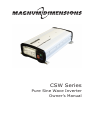
CSW Series
Pure Sine Wave Inverter
Owner’s Manual
Thank you from all of us at Sensata Technologies for purchasing this CSW
Series inverter. The CSW Series includes the CSW412, CSW1012 and
CSW2012 inverters; all under the Magnum-Dimensions brand from Sensata
Technologies. We understand that you have many purchasing options in the
marketplace and are pleased that you have decided on this product.
At Sensata, we are committed to providing you with quality products and
services, and hope that your experience with us is pleasant and professional.
Disclaimer of Liability
Since the use of this manual and the conditions or methods of installation,
operation, use and maintenance of the CSW Series inverter is beyond the
control of Sensata Technologies, this company does not assume responsibility
and expressly disclaims liability for loss, damage or expense, whether direct,
indirect, consequential or incidental, arising out of or in any way connected
with such installation, operation, use, or maintenance.
Note as well that while every precaution has been taken to ensure the
accuracy of the contents of this manual, the specifications and product
functionality may change without notice. Sensata assumes no responsibility
for errors or omissions.
Restrictions on Use
The CSW Series inverter may only be used in life-support devices or systems
with the express written approval of Sensata Technologies. Failure of the
CSW Series inverter can reasonably be expected to cause the failure of that
life-support device or system, or to affect the safety or effectiveness of that
device or system. If the CSW Series inverter fails, it is reasonable to assume
that the health of the user or other persons may be endangered.
Copyright Notice
Copyright © 2015 by Sensata Technologies. All rights reserved. Permission to
copy, distribute, and/or modify this document is prohibited without express
written permission from Sensata.
Document Information
Description – CSW Series Owner’s Manual
Part Number and Revision – 64-0063 Rev B
Date Published – April 2015
This manual is printed without color for cost savings. However, this entire
manual is available with many of the figures in color and can be downloaded at
www.magnum-dimensions.com.
Contact Information
For Magnum-Dimensions products:
Sensata Technologies
Phone: 425-353-8833
2211 West Casino Rd.
Fax: 425-353-8390
Everett, WA 98204
Web: www.magnum-dimensions.com
Record the unit’s model and serial number in case you need to provide
this information in the future. It is much easier to record this information
now, instead of trying to gather it after the unit has been installed.
Model:
CSW412
Serial Number:
BE
CSW1012
AU
CSW2012
BD
© 2015 Sensata Technologiesi
IMPORTANT PRODUCT SAFETY INSTRUCTIONS
This manual contains safety instructions that must be followed during the
installation and operation of this product. Read all instructions and safety
information on the inverter and in this manual before installing or using.
Safety Symbols
To reduce the risk of electrical shock, fire, or other safety hazard, the
following safety symbols have been placed throughout this manual to
indicate dangerous situations and important safety instructions.
WARNING: Indicates that failure to take a specified action could
result in physical harm to the user.
CAUTION: Indicates that failure to take a specified action could result
in damage to the equipment.
Info: Indicates information that emphasizes or supplements important
points of the main text.
Product Safety Warnings
WARNINGS: Failure to follow the instructions below and in this
manual can result in death or serious injury.
•
All electrical work must be performed in accordance with local, state and
federal electric codes.
This product is designed for indoor/compartment installation. Do not
expose to rain, snow, moisture, or liquids of any type.
Use insulated tools to reduce the chance of electrical shock or accidental
short circuits. Be sure to remove all jewelry such as rings, watches,
bracelets, etc., when installing or performing maintenance on the inverter.
Always disconnect the batteries or energy source prior to installing or
performing maintenance on the inverter. Live power may be present at
more than one point since an inverter utilizes both batteries and AC.
Do not cover or obstruct any air vent openings and/or install in a zeroclearance compartment - always operate unit in an open area.
When working with electrical equipment or lead acid batteries, have
someone nearby in case of an emergency.
Study and follow all the battery manufacturer’s specific precautions when
installing, using, and servicing the battery connected to the inverter.
While working with batteries, wear eye protection and gloves, and avoid
touching your eyes. Keep fresh water and soap on hand in the event battery
acid comes in contact with eyes. If this occurs, cleanse right away with soap
and water for a minimum of 15 minutes and seek medical attention.
Batteries produce explosive gases, DO NOT smoke or have an open spark
or fire near the system.
Avoid dropping any metal tool or object on the battery. Doing so could
create a spark or short circuit which goes through the battery or another
electrical tool and may cause an explosion.
Shock Hazard! Keep away from children!
These inverters provide household AC, treat the AC output sockets the
same as regular wall AC sockets at home.
Explosion hazard! DO NOT use this inverter in the vicinity of flammable
fumes or gases (such as propane tanks or large engines).
These inverters contain no user-serviceable parts. See the Warranty
section for how to handle service issues.
•
•
•
•
•
•
•
•
•
•
•
•
•
ii
© 2015 Sensata Technologies
Table of Contents
1.0Introduction.............................................................................. 1
1.1 Features - CSW1012 and CSW2012.............................................. 1
1.2 Features - CSW412.................................................................... 3
1.3 Regulatory Compliance............................................................... 4
2.0Installation............................................................................... 5
2.1Pre-Installation......................................................................... 5
2.1.1 Installation Guidelines......................................................... 5
2.1.2 Unpacking and Inspection.................................................... 5
2.1.3 Tools Required.................................................................... 5
2.2 Locating and Mounting the Inverter............................................. 8
2.3 Wiring the Inverter – General Requirements............................... 11
2.3.1 Wiring Requirements......................................................... 11
2.3.2 Torque Requirements......................................................... 11
2.4 DC Wiring.............................................................................. 12
2.4.1 DC Wire Sizing................................................................. 13
2.4.2 DC Overcurrent Protection.................................................. 14
2.4.3 DC Grounding................................................................... 14
2.4.4 DC Cable Connections........................................................ 14
2.4.5 Wiring the Battery Bank..................................................... 15
2.4.6 Appliances and Run Time................................................... 15
2.4.7 Wiring the Inverter to the Battery Bank............................... 16
2.5 Testing the Inverter................................................................. 18
2.5.1 Inverter Functional Test..................................................... 18
2.5.2 GFCI Function Test............................................................ 18
3.0Operation................................................................................ 19
3.1 CSW412 Operation.................................................................. 19
3.2 CSW1012 and CSW2012 Operation............................................ 20
3.3 Understanding Loads............................................................... 21
3.4 System Maintenance................................................................ 21
4.0Troubleshooting...................................................................... 22
5.0 Specifications.......................................................................... 23
6.0 Limited Warranty.................................................................... 24
6.1 How to Receive Warranty Service.............................................. 24
© 2015 Sensata Technologiesiii
List of Figures
Figure
Figure
Figure
Figure
Figure
Figure
Figure
Figure
Figure
Figure
Figure
Figure
Figure
1-1, Front Panel Features (CSW1012 and CSW2012)..................... 1
1-2, Back Panel Features (CSW1012).......................................... 2
1-3, Back Panel Features (CSW2012).......................................... 2
1-4, Front Panel Features (CSW412)............................................ 3
1-5, Back Panel Features (CSW412)............................................ 4
2-1, Basic System Diagram........................................................ 6
2-2, RV OEM System Diagram.................................................... 7
2-3, Approved Mounting Positions............................................... 9
2-4 CSW412 Dimensions............................................................ 9
2-5 CSW1012 Dimensions........................................................ 10
2-6 CSW2012 Dimensions........................................................ 10
2-7, DC Cable to Battery Terminals............................................ 17
2-8, DC Cable to Inverter’s DC Terminals................................... 17
Tables
Table
Table
Table
Table
Table
Table
Table
iv
2-1,
2-2,
2-3,
3-1,
4-1,
4-2,
5-1,
DC Terminal - Torque Requirements..................................... 11
DC Wire/Overcurrent Device for Rated Use............................ 13
Appliance Power Consumption and Run Time......................... 15
Examples of Digital Display Readings.................................... 20
Troubleshooting Guide........................................................ 22
CSW1012 and CSW2012 Inverter Error Codes....................... 22
CSW Series Specifications................................................... 23
© 2015 Sensata Technologies
1.0 Introduction
1.0Introduction
Congratulations on your purchase of the CSW Series pure sine wave inverter.
The CSW Series includes the CSW412, CSW1012 and CSW2012 inverters;
under the Magnum-Dimensions brand from Sensata Technologies. The CSW
Series inverters are “pure” sine wave inverters designed to be powerful, yet
simple to operate, and will provide you with reliable AC power for trouble-free
use. Please read this chapter to familiarize yourself with the features and
benefits of your CSW Series inverter.
1.1
Features - CSW1012 and CSW2012
The front panels of the CSW1012 and CSW2012 inverters are similar and are
equipped with the following features (see Figure 1-1):
1. Serial Number – the unique identification number assigned to each unit
(with a model-specific prefix). Note: Enter your inverter’s serial number in
the table at the bottom of page i. It is to easier to record this information
now, instead of trying to gather it after the unit has been installed.
2. GFCI – a Ground Fault Circuit Interrupter protected AC outlet. The GFCI
outlet quickly stops the flow of electricity in the event a ground fault occurs
on the device that is plugged into the inverter.
3. Status Indicator – an at-a-glance LED that provides the inverter’s
status—lights green, red, or amber (see Section 3.0 Operation).
4. Digital Display – a three-character alphanumeric display that shows
the inverter’s measured battery voltage, total AC output power, and any
error or warning codes.
5. Power/Select Button – a momentary button switch that allows the
inverter to be quickly turned on or off.
6. Remote Port – a RJ11 connector that allows an optional remote switch to
be connected via a remote cable. Note: Remote switch is sold separately
(PN: CSW-RS).
7. USB Port – allows USB-enabled devices to be powered and charged.
3
1
4
5
6
2
7
Figure 1-1, Front Panel Features (CSW1012 and CSW2012)
© 2015 Sensata Technologies1
1.0 Introduction
The back panels of the CSW1012 and CSW2012 inverters are equipped with
the following features (See Figure 1-2 and Figure 1-3):
8. Cooling Fan(s) – an intake cooling fan that automatically turns on when
the inverter’s internal temperature rises above 122°F (50°C). The fan turns
off when the inverter’s internal temperature falls below 122°F (50°C).
9. Mounting Flanges (front and rear) – used to mount and secure the
inverter to a shelf/wall.
10. DC Negative Terminal (black) – the inverter’s connection to the
negative terminal on the 12 VDC battery bank.
11. DC Positive Terminal (red) – the inverter’s connection to the positive
terminal on the 12 VDC battery bank.
12. Model Number – the model number of the inverter (i.e., CSW1012),
and other information.
13. DC Chassis Ground Connection – the connection that is used to tie
the exposed chassis of the inverter to the DC grounding system. The DC
grounding system could be the vehicle’s chassis, the DC grounding bus,
or to the engine’s negative bus.
10
8
11
12
9
13
Figure 1-2, Back Panel Features (CSW1012)
11
12
10
8
13
9
Figure 1-3, Back Panel Features (CSW2012)
2
© 2015 Sensata Technologies
1.0 Introduction
1.2
Features - CSW412
The CSW412 inverter is equipped with the following front panel features (see
Figure 1-4):
1. Power Indicator – an at-a-glance LED that lights green when the inverter
is on. (see Section 3.0 Operation).
2. Fault Indicator – an at-a-glance LED that comes on to indicate an
inverter fault (see Section 4.0 for troubleshooting).
3. USB Port – allows USB-enabled devices to be powered and charged.
4. ON/OFF Power Switch – a 2-position switch that turns the inverter
on and off.
5. Serial Number – the unique identification number assigned to each unit
(with a model-specific prefix). Note: Enter your inverter’s serial number in
the table at the bottom of page i. It is to easier to record this information
now, instead of trying to gather it after the unit has been installed.
6. GFCI – a Ground Fault Circuit Interrupter protected AC outlet. The GFCI
outlet quickly stops the flow of electricity in the event a ground fault occurs
on the device that is plugged into the inverter.
1
2
5
3
6
4
Figure 1-4, Front Panel Features (CSW412)
© 2015 Sensata Technologies3
1.0 Introduction
The back panel of the CSW412 inverter is equipped with the following
features (see Figure 1-5):
8. Cooling Fan – an intake cooling fan that automatically turns on when the
inverter’s internal temperature rises above 122 °F (50 °C). The fan turns
off when the inverter’s internal temperature falls below 122 °F (50 °C).
9. DC Negative Terminal (black) – the inverter’s connection to the
negative terminal on the 12 VDC battery bank.
10. Mounting Flanges (front and rear) – used to mount and secure the
inverter to a shelf/wall.
11. Model Number – the model number of the inverter (i.e., CSW412), and
regulatory compliance information.
12. DC Positive Terminal (red) – the inverter’s connection to the positive
terminal on the 12 VDC battery bank.
8
11
9
12
10
Figure 1-5, Back Panel Features (CSW412)
1.3
Regulatory Compliance
The CSW Series inverters are intended to be used for land vehicles (RVs
or trucks) or marine craft. They are listed to UL Standard 458, 5th Edition
(Power Converters/Inverters and Power Converter/Inverter Systems for
Land Vehicles and Marine Crafts) for use in the US; and are also certified to
CSA Standard C22.2 No. 107.1-01 (General Use Power Supplies) for use in
Canada.
These inverters have been tested and certified to product safety standards by
Intertek Testing Services (known as ETL), which is a Nationally Recognized
Testing Laboratory (NRTL). NRTLs are qualified organizations that meet
Occupational Safety and Health Administration (OSHA) regulations to
perform independent safety testing and product certification.
4
© 2015 Sensata Technologies
2.0 Installation
2.0Installation
Review this section and all safety instructions before proceeding with the
installation of your inverter.
WARNING: Installations should be performed by qualified
personnel, such as a licensed or certified electrician. The installer
determines which safety codes apply and ensures all applicable
installation requirements are followed. Applicable installation codes
vary depending on the specific location and application.
WARNING: Before installing, review the “Important Product Safety
Information” on page ii and adhere to all cautionary markings located
on the inverter and on the batteries.
2.1Pre-Installation
Before proceeding, read the entire Installation section to determine how
best to install your CSW Series inverter. The more thorough you plan in the
beginning, the better your inverter needs will be met. Depending on your
application, there are simplified system diagrams shown in Figure 2-1 and
Figure 2-2. These should be reviewed to assist you in planning and designing
your installation. These drawings are not intended to override or to restrict
any national or local electrical codes, and should not be the determining
factor as to whether the installation is compliant, that is the responsibility of
the electrician and the onsite inspector.
2.1.1 Installation Guidelines
•
•
•
•
Before connecting any wires, determine the cable routes throughout the
vehicle or boat, both to and from the inverter.
Always check for existing electrical, plumbing, or other areas of potential
damage BEFORE drilling or cutting into walls.
Make sure all wires have a smooth bend radius and do not become kinked.
If installing this inverter in a boat, RV or truck, ensure the conductors
passing through walls, bulkheads, or other structural members are
protected. This minimizes insulation damage (such as chafing), which
can be caused by vibration or constant rubbing.
2.1.2 Unpacking and Inspection
Carefully remove the inverter from its shipping container and inspect all
contents. Verify the following items are included:
•
CSW Series inverter
•
CSW Series Owner’s Manual
If items appear to be missing or damaged, contact your authorized MagnumDimensions dealer or Magnum-Dimensions directly.
*** Save your proof-of-purchase as a record of your ownership; it
is needed if the unit should require in-warranty service. ***
2.1.3 Tools Required
Installing the inverter is simple and requires the following:
• Adjustable wrench (10-13 mm) • Level
• #10 Mounting screws (x4) • Pencil • Phillips screwdriver
• Drill
• Drill bits
© 2015 Sensata Technologies5
2.0 Installation
AC Source
AC
Main Panel
(120VAC, 60 Hz Sinewave)
(Branch Circuit
Breaker to
Transfer
Switch:
15A max)
CSW-TS15
Transfer Switch
AC IN
AC OUT
CSW Series
Inverter
AC
Sub-Panel
DC
Disconnect
AC
Outlet
DC
Ground
(Vehicle
chassis, DC
ground bus,
or engine
negative bus)
AC Loads
(15A max)
Fuse
TV
Battery
Bank
Tools
DVD
Figure 2-1, Basic System Diagram
6
© 2015 Sensata Technologies
2.0 Installation
AC Source
AC
Main Panel
(120VAC, 60 Hz Sinewave)
(Branch Circuit
Breaker to
Transfer
Switch:
15A max)
CSW-TS15
Transfer Switch
AC IN
AC OUT
CSW Series
Inverter
DC
Disconnect
DC
Ground
(Vehicle
chassis, DC
ground bus,
or engine
negative bus)
Fuse
Battery
Bank
Dedicated
AC Load
(15A max)
Notes: The NEC requires overcurrent
protection for wiring and equipment in
both AC and DC circuits. As shown in
this diagram, the RVIA allows the
following application where an
inverter is installed in a RV.
Pass-thru mode: When the AC source
(generator or shore power) powers
loads thru a transfer switch (i.e., passthru mode), the conductor from the
transfer switch to the dedicated load
will be protected as long as the branch
rated circuit breaker at the AC source
does not exceed the ampacity of the
conductor feeding the dedicated load.
Inverter Mode: When the inverter is
powering loads using power from the
battery (i.e., Inverter mode), the
conductor from the inverter output to
the dedicated load will be protected as
long as the ampacity of the conductor
is sized based on the inverter’s AC
output rating. In Inverter mode, the
inverter has overcurrent protection to
limit the output current and to protect
the conductor.
Figure 2-2, RV OEM System Diagram
© 2015 Sensata Technologies7
2.0 Installation
2.2
Locating and Mounting the Inverter
WARNINGS:
• Do not mount the inverter near any flammable or combustible
fluid or components.
• Provide adequate clearance/ventilation to the inverter. Do not
cover or obstruct any air vent openings and/or install in a zeroclearance compartment.
The inverter should only be installed and mounted in a location that meets
the following requirements:
Clean and dry – The inverter should not be installed in an area that allows
dust, fumes, insects, or rodents to enter or block the inverter’s ventilation
openings. This area also must be free from any risk of condensation, water,
or any other liquid that can enter or fall on the inverter. Inverter failure under
these conditions is not covered under warranty.
Cool – The inverter should be protected from direct exposure to the sun or
to any equipment that produces extreme heat. The ambient temperature
should be between 32° F (0° C) and 104° F (40° C); note that the inverter’s
output specifications are rated at 77° F (25° C), so the cooler the better.
Ventilated – In order for the inverter to provide full output power and
avoid over-temperature fault conditions, do not cover or block the inverter’s
ventilation openings, or install this inverter in an area with limited airflow.
Allow a minimum airspace clearance of 3” (7.6 cm) around the unit to provide
optimum ventilation.
Safe – Keep any flammable/combustible material (e.g., paper, cloth, plastic,
etc.,) that may be ignited by heat, sparks, or flames at a minimum distance
of 2 feet (60 cm) away from the inverter. Do not install in any area that
contains extremely flammable liquids like gasoline or propane, or in locations
that require ignition-protected devices.
Close to the battery bank – As with any inverter, it should be located as
close to the batteries as possible. Long DC wires tend to lose efficiency and
reduce the overall performance of an inverter. However, the unit should not
be installed in the same compartment as the batteries or mounted where it
will be exposed to gases produced by the batteries. These gases are corrosive
and will damage the inverter; also, if these gases are not ventilated and if
allowed to collect, they could ignite and cause an explosion.
Accessible – Do not block access to the front or back of the inverter. Allow
room to view any indictors or digital display and to access the AC and DC
wiring connections—they will need to be checked and tightened periodically.
Orientating the inverter - When mounted indoors, the CSW Series inverter
can be mounted on/underneath a horizontal surface (shelf or table) or on
a vertical surface (wall or bulkhead) with the DC terminals facing left or
right. Additionally, the CSW1012 and CSW2012 can be mounted with the DC
terminals facing up (CSW412 cannot be mounted with terminal’s facing up
or down)—do not mount with the DC terminals facing downward (see Figure
2-3). When mounted in an RV, mount flat on a horizontal surface only.
After determining your mounting position, use the base of the inverter’s chassis
as a template to mark your mounting screw locations (or, refer to the dimensions
in Figures 2-4 thru 2-6). Remove the inverter and drill pilot holes into the
mounting surface. Secure the inverter to the surface using the appropriate
corrosion-resistant hardware. If this unit is used in a mobile application, you
may want to place flexible washers or bushings between the mounting surface
and the inverter’s mounting flanges to reduce vibration.
8
© 2015 Sensata Technologies
2.0 Installation
For Indoor Use:
Flat on a
horizontal
surface
(right side
up or
upside
down).
CSW1012 and
CSW2012 only:
CSW412 cannot
be mounted with
DC terminals
facing up.
DC terminals to the right,
left or to the top.
For RV Installation:
Mount flat on a
horizontal surface only
Figure 2-3, Approved Mounting Positions
6.3’’ (16.1 cm)
Top
6.9’’ (17.5 cm)
5.8’’ (14.7 cm)
7.9’’ (20 cm)
Front (AC Side)
Back (DC Side)
3.4’’
(8.7 cm)
Figure 2-4 CSW412 Dimensions
© 2015 Sensata Technologies9
2.0 Installation
6.9’’ (17.5 cm)
Top
6.3’’ (16.1 cm)
10.3’’ (26.2 cm)
12.6’’ (32.1 cm)
Front (AC Side)
Back (DC Side)
3.4’’
(8.4 cm)
Figure 2-5 CSW1012 Dimensions
9.1’’ (23 cm)
Top
8.5’’ (21.6 cm)
13.4’’ (34 cm)
16.5’’ (41.9 cm)
Back (DC Side)
Front (AC Side)
3.5’’
(8.9 cm)
Figure 2-6 CSW2012 Dimensions
10
© 2015 Sensata Technologies
2.0 Installation
2.3
Wiring the Inverter – General Requirements
This section describes the requirements and recommendations for wiring the
CSW Series inverter. Before wiring the inverter, carefully read all instructions.
WARNING: Wiring should meet all local codes/standards and be
performed by qualified personnel (i.e., licensed electrician).
2.3.1 Wiring Requirements
•
•
•
•
•
All conductors that are at risk for physical damage must be protected
by tape or placed in a raceway.
Always check for existing electrical, plumbing, or other areas of
potential damage prior to making cuts in structural surfaces or walls.
Where DC wiring must cross AC or vice-versa, try to make the wires at
the crossing point perpendicular (90 degrees) to one another.
DC overcurrent protection must be provided as part of the installation.
Use only copper wires with a minimum temperature rating of 75° C
(194° F).
2.3.2 Torque Requirements
•
All wiring to the DC terminals and DC ground connection should be
checked periodically (once a month) for proper tightness. For the torque
requirements, refer to Table 2-1. If you don’t have a torque wrench,
ensure all connections are tight.
Table 2-1, DC Terminal - Torque Requirements
Inverter
Model
DC
Terminals
Torque
Requirements
Torque Wrench
Size Needed
CSW412
Hex Cap
screws
52 to 58 lbf-in
(5.9 to 6.5 N-m)
12 mm wrench
CSW1012
M6 x 1.0
Hex nuts
79 to 96 lbf-in
(8.9 to 10.9 N-m)
10 mm wrench
CSW2012
M8 x 1.25
Hex nuts
16 to 21 lbf-ft
(22 to 28 N-m)
13 mm wrench
© 2015 Sensata Technologies11
2.0 Installation
2.4
DC Wiring
This section describes the inverter’s required DC wire sizes, the recommended
disconnect/overcurrent protection, and how to make the DC connections to
the inverter and the battery bank.
WARNING: Even though DC voltage can be regarded as “low
voltage”, significant hazards may be present, particularly from short
circuits of the battery system.
CAUTION: The inverter is NOT reverse polarity protected—which
means if the negative and positive battery voltage is connected to the
inverter backwards, the inverter will likely be damaged. Use a voltmeter
to verify the correct polarity BEFORE connecting the DC wires.
CAUTION: DO NOT connect the battery cables to the inverter until
all wiring is complete and the correct DC voltage and polarity have
been verified.
Refer to Figure 2-7 when connecting the DC wires to the battery, and to
Figure 2-8 when connecting to the inverter. Also, consider the following
requirements to ensure maximum performance:
• The DC positive and negative cables connected to the inverter from the
battery bank should be tied together with wire ties/straps or electrical
tape approximately every 6 inches (15.3 cm). This helps improve the
surge capability and reduces the effects of inductance, which improves
the inverter waveform and reduces the wear of the inverter’s filter
capacitors. Keeping the battery cables close together also reduces the
chance of radio frequency interference.
• Be aware that over-tightening or misthreading the nuts on the DC
terminals can cause the bolts to strip and snap/break off.
• Make sure cables have a smooth bend radius and do not become kinked.
Follow existing wire runs where possible.
• Crimped and sealed copper ring terminal lugs with at least a 6 mm
(1/4”) bolt hole to connect the DC wires to the inverter’s DC terminals.
• The battery bank voltage MUST be between 10.5-15.5 (10.5 - 15.75 for
the CSW412) for the inverter to operate. If the voltage exceeds 16.0V,
the inverter may be damaged.
• To ensure the maximum performance from the inverter, all connections
from the battery bank to the inverter should be minimized. The
exceptions are the DC fuse and disconnect, or the DC circuit breaker—
required at the battery to protect the DC wiring—in the positive line. Any
other additional connection will contribute to additional voltage drops,
and these extra connection points may loosen during use.
• A brief spark or arc may occur when connecting the battery cables to the
inverter DC terminals; this is normal and due to the inverter’s internal
capacitors being charged.
• Before routing the wiring, color code the DC cables/wires with colored
tape or heat shrink tubing: RED for positive (+); WHITE for negative (–);
and GREEN (or bare copper) for DC ground, to avoid polarity problems.
• A cable should be connected directly from the inverter negative terminal
to the battery negative connection; this ensures the inverter has a
reliable return path directly to the battery. Do not use the chassis in
place of the battery negative connection to the inverter.
12
© 2015 Sensata Technologies
2.0 Installation
2.4.1 DC Wire Sizing
It is important to use the correct sized DC wire to achieve maximum efficiency
from the system and to reduce fire hazards associated with overheating. Always
keep your wire runs as short as practical to prevent low voltage shutdowns
and to keep the DC breaker from nuisance tripping (or open fuses) because
of increased current draw. See Table 2-2 to select the minimum DC wire
size (and corresponding overcurrent device) required based on your inverter
model. The cable sizes listed in this table are required in order to reduce
stress on the inverter, minimize voltage drops, increase system efficiency, and
ensure the inverter’s ability to surge heavy loads.
If the distance from the inverter to the battery is >5 feet (1.5 m), the DC wire
will need to be increased. Longer cable distances affect the performance of the
inverter. See the lower part of Table 2-2 to determine the minimum DC wire
size needed for various distances greater than 5 feet—based on your inverter
model.
DC Wire Size Exception: In an OEM RV application, smaller DC wire (with
appropriate overcurrent protection) may be used if the inverter will only be
connected to a dedicated load (as shown in Figure 2-2), and the inverter and
dedicated load have been thoroughly tested and sold together by the OEM
as a complete system.
Table 2-2, DC Wire/Overcurrent Device for Rated Use
Inverter Model
CSW412
CSW1012
CSW2012
Full Load C urrent
38 amps
94 amps
187 amps
Maximum C ontinuous
C urrent¹
46 amps
113 amps
224 amps
Minimum DC Ground
Wire Size 2
#8 AWG
(8.36 mm²)
#8 AWG
(8.36 mm²)
#8 AWG
(8.36 mm²)
Minimum DC Wire Size
[75˚C rating in free air]
#10 AWG
(5.26 mm²)
[50 amps]
#2 AWG
(33.6 mm²)
[170 amps]
#3/0 AWG
(85 mm²)
[310 amps]
Maximum DC Fuse Size
Increased
size for
longer
distance
50 amps with 150 amps with 300 amps with
time delay
time delay
time delay
▼
▼
▼
5 - 10 feet
(1.5 - 3 m)
#8 AWG
(8.36 mm²)
#1 AWG
(42.4 mm²)
#4/0 AWG
(107 mm²)
10 - 15 feet
(3 - 4.6 m)
#6 AWG
(13.3 mm²)
#1/0 AWG
(53.5 mm²)
Not
recommended
Note 1 - Maximum Continuous Current is based on the inverter’s continuous
power rating at the lowest input voltage with an inefficiency factor.
Note 2 - The grounding conductor for the DC system shall meet the sizing
requirements specified in the NEC for the application, but must be no smaller than
8 AWG copper. In some applications, the DC grounding conductor is required to
be no less than the wire size of the DC positive/negative cables.
© 2015 Sensata Technologies13
2.0 Installation
2.4.2 DC Overcurrent Protection
For safety reasons and to comply with electrical code regulations, DC
overcurrent protection must be provided as part of the installation. The DC
overcurrent protection device must be installed in the positive DC cable line,
it can be a fuse (with a disconnect switch) or a circuit breaker and must be
DC-rated. It must be correctly sized according to the size of DC cables being
used, which means it is required to open before the cable reaches its maximum
current carrying capability, thereby preventing a fire. The NEC requires both
overcurrent protection and a disconnect switch.
Because batteries can deliver thousands of amps in an instant during a short,
you are required to install a DC-rated fuse (or circuit breaker) that has a
interrupt current rating (known as Amps Interrupting Current or AIC) that can
withstand the short-circuit current without explosion or damage. If a fuse is used
as an overcurrent device, a Class-T type or equivalent is highly recommended
when used with inverters. A Class-T fuse is rated for DC operation, can handle
very high short-circuit currents (up to 100,000 amps), and has a time delay
that allows for momentary current surges from the inverter without opening
the fuse. In some installations, if the combined short-circuit current of all the
batteries in the bank is determined to be 2,700 amps or less, then an ANL type
of fuse may be used—if in doubt, use a Class-T fuse. See Table 2-2 for the fuse
size (coordinated with the DC wire size) recommended for your CSW inverter.
2.4.3 DC Grounding
The inverter should always be connected to a permanent, grounded wiring
system. The idea is to connect the metallic chassis of the various enclosures
together to have them at the same voltage potential, to reduce the possibility
for electric shock. For most installations, the inverter chassis and the negative
battery conductor are connected to the system’s ground bond via a safety
grounding conductor (bare wire or green insulated wire) at only one point in
the system. The grounding conductor for the DC system shall meet the sizing
requirements specified in the NEC for the application, but must be no smaller
than 8 AWG copper. For instance: An inverter used in a marine application under
ABYC guidelines requires the size of the DC grounding conductor to be of an
ampacity equal to or one size less than that of the DC positive conductor. See
Table 2-2 for the minimum ground wire size recommended for your inverter.
Info: If the inverter is installed in a vehicle, connect the battery
negative cable directly to the inverter’s negative terminal. DO NOT
connect the negative battery cable meant for the inverter to the
vehicle’s frame/safety ground.
2.4.4 DC Cable Connections
Do not put anything between the battery cable ring lug and the battery
post (see Figure 2-7), or the flat metal part of the inverter’s DC terminal
(see Figure 2-8). When connecting the battery cable, it should be placed
directly against the battery post or inverter terminal. Incorrectly installed
hardware causes a high resistance connection which could lead to poor
inverter performance, and may melt the cable and terminal connections.
See Table 2-1 for the torque requirements.
Info: The DC terminal and Hex nuts on the CSW1012 and CSW2012
are made of stainless steel, which has a high likelihood of galling or
thread seizing while being tightened—causing the bolts to strip or
to snap/break off. To reduce this risk, use an anti-seize lubricant,
tighten the fasteners slowly (at low rpms) without interruption, and
apply only light pressure.
14
© 2015 Sensata Technologies
2.0 Installation
2.4.5 Wiring the Battery Bank
WARNING: Lethal currents will be present if the positive and
negative cables attached to the battery bank touch each other.
During the installation and wiring process, ensure the cable ends
are insulated or covered to prevent touching/shorting the cables.
Info: DO NOT connect the DC wires from the battery bank to
the inverter until 1) all DC wiring is complete, 2) the correct DC
overcurrent protection has been installed, and 3) the correct DC
voltage and polarity have been verified.
Depending upon the voltage of the batteries (6 or 12 VDC), the batteries
must be wired in series, parallel, or series-parallel to provide the correct
voltage. The interconnecting DC wires must be sized and rated exactly the
same as those used between the battery bank and the inverter.
Place the batteries as close as practical to the inverter, preferably in an
insulated and ventilated enclosure. Allow adequate space above the batteries
to access the terminals and vent caps (as applicable). Also, allow at least 1”
(2.5 cm) of space between the batteries to provide good air flow. DO NOT
mount the batteries directly under the inverter.
CAUTION: Install batteries in a well ventilated area. Batteries
can produce explosive gasses. For compartment or enclosure
installations, always vent batteries to the outside.
Info: To ensure the best performance from your inverter system,
batteries should be of the same size, type, rating, and age. Do not
use old or untested batteries.
2.4.6 Appliances and Run Time
The CSW Series inverters can power a wide range of household appliances
including small motors, hair dryers, clocks, and other electrical devices.
As with any appliance using batteries for power, there is a certain length
of time that it can run—this is called “run time.” Table 2-3 below provides
estimates of power consumption and run time for various appliances using a
12V-120AH battery bank.
Table 2-3, Appliance Power Consumption and Run Time
Load
Consumption
Estimated Run Time
Cordless Phone
5W
180 hrs
Clock/Radio
8W
135 hrs
Table Lamp
40W/60W
27 hrs/18 hrs
80W
15 hrs
20” LCD TV
100W
11.5 hrs
Refrigerator (18 cu ft)
120W
9 hrs
Freezer (8.8 cu ft)
Sump Pump (1/2 hp)
350W
3 hrs
Microwave (mid-size)
1000W
49 min
Coffee Maker
1200W
37 min
© 2015 Sensata Technologies15
2.0 Installation
2.4.7 Wiring the Inverter to the Battery Bank
CAUTION: The inverter is NOT reverse polarity protected—if the
positive terminal of the battery is connected to the negative terminal
of the inverter and vice versa, severe damage to the inverter will
occur and this will void the warranty. Before connecting the DC wires
from the batteries to the inverter, verify the correct battery voltage
and polarity using a voltmeter. If necessary, color code the cables
(with colored tape): red for positive (+), and white for negative (-)
to avoid polarity confusion.
Info: The DC overcurrent device (i.e., circuit breaker or fuse) must
be placed in the positive (red) DC cable line between the inverter’s
positive DC terminal and the battery’s positive terminal (red)—as
close to the battery as possible. For maximum protection, install it
within 18 inches (45 cm) of the battery.
Follow the steps below to wire the inverter to the battery bank:
1. Route an appropriately sized DC negative wire (marked white) from the
negative terminal of the battery bank to the inverter’s negative terminal
(Item 10, Figures 1-2 and 1-3; Item 9, Figure 1-5).
2. Mount the fuse/disconnect assembly (or circuit breaker) as near as
practical to the batteries and leave open (i.e., no power to inverter).
WARNING: DO NOT close the DC circuit breaker or connect the
fuse to connect battery power to the inverter at this time. This will
occur after the installation is complete.
CAUTION: If connecting live battery cables to the inverter DC
terminals, a brief spark or arc may occur; this is normal and due
to the inverter’s internal capacitors being charged.
3. Route and connect an appropriately sized DC positive wire (marked red)
from the inverter’s positive DC terminal (Item 11, Figures 1-2 and 1-3;
Item 13, Figure 1-5) to one end of the fuse/disconnect assembly (or
circuit breaker).
4. Connect a short wire (same rating as the DC wires) to the other side of
the DC circuit breaker (or one end of the fuse/disconnect assembly) and
the other end of that short wire to the positive terminal of the battery
bank (see Figure 2-1 or Figure 2-2 for reference). This is essential to
ensure even discharging across the entire battery bank.
5. Ensure the DC wire connections (on the batteries, inverter, and DC
circuit breaker/fuse) are flush on the surface of the DC terminals, and
all hardware used to hold these connections are stacked correctly (see
Figures 2-7 and 2-8). Verify all DC connections on the inverter are torqued
correctly (see Table 2-1), and the total cable distance from the inverter to
the battery is within the requirement of Section 2.4.1 (DC Wire Sizing).
6. Once the DC connections are completely wired and tested, coat the
terminals with an approved anti-oxidizing spray.
7. If the batteries are in an enclosure, perform a final check of the connections
to the battery terminals, then close and secure the battery enclosure.
8. Route an appropriately sized DC ground wire (see Table 2-2) from the
inverter’s DC chassis ground connection to a dedicated system ground.
9. Once the entire installation is complete and all connections verified, close
the fuse disconnect (or circuit breaker) to provide power to the inverter.
16
© 2015 Sensata Technologies
2.0 Installation
DC cable
with ring lug
nut
lock washer
BATTERY
battery terminal
flat washer
battery
post
bolt
Verify that the
DC cable lugs are flush
with the battery terminals.
Figure 2-7, DC Cable to Battery Terminals
M6-1.0 hex nut
lock washer
#12 flat washer
DC cable
with ring lug
Inverter’s DC
+ terminal
CSW1012
Inverter
CAUTION:
Ensure nothing is placed
between the DC terminal
and the ring lug.
Figure 2-8, DC Cable to Inverter’s DC Terminals
© 2015 Sensata Technologies17
2.0 Installation
2.5
Testing the Inverter
Before proceeding, you must first test whether the inverter was successfully
installed. Use the functional test below to test the inverter, and then perform
the GFCI test that follows to ensure the protection device is functioning
properly.
2.5.1 Inverter Functional Test
After all electrical connections to the inverter and batteries have been
completed, plug a small AC load (e.g., 40W light bulb or small appliance)
into the GFCI’s outlet, and follow these steps to test the installation and the
inverter’s operation.
• CSW412 inverters:
1. Toggle the ON/OFF Power Switch to the ON (I) position to turn the
unit on.
2. The Power Indicator will turn on to indicate that the AC output power
is available.
3. Check that the AC load is on (i.e., the bulb lights).
Note: If the bulb does not light, the GFCI may have tripped. Reset the
GFCI by pressing the RESET button.
•
CSW1012 and CSW2012 Inverters:
1. Press and hold the Power/Select button until a beep sound is heard
(about 1 second). The Status light turns on.
2. Check that the digital display alternately shows the inverter’s
measured battery voltage and output power.
3. Check that the AC load is on (i.e., the bulb lights).
Note: If the bulb does not light, the GFCI may have tripped. Reset the
GFCI by pressing the RESET button.
If the inverter passes all steps, it is functioning properly and ready for use.
If the inverter fails any of the steps, refer to the troubleshooting information
in Section 4.0.
2.5.2 GFCI Function Test
Use the steps below to periodically test the GFCI to ensure it is functioning
properly.
1. Turn the inverter on.
2. Plug a small AC load (e.g., 40W light bulb) into the GFCI’s outlet.
3. Check that the AC load is on (i.e., the bulb lights).
4. Press the GFCI’s TEST button. The GFCI’s RESET button should pop out,
and the power should shut off (light bulb goes out).
Note: If the bulb remains lit or the RESET button does not pop out, the
GFCI may not be functioning properly.
5. Press the RESET button. The AC load should come back on (bulb lights
again).
18
© 2015 Sensata Technologies
3.0 Operation
3.0Operation
When the inverter is properly connected to batteries and turned on, the
direct current (DC) from the batteries is transformed into a pure sine wave
alternating current (AC). This AC is similar to the voltage provided by
your utility and is used to power any electrical appliances (i.e., AC loads)
connected to the inverter’s output.
3.1
CSW412 Operation
The CSW412 inverter uses a front panel that contains a power on/off switch,
two LED indicators, a USB port, and a GFCI AC output receptacle.
Turning the Inverter on and off
The ON/OFF Power switch is used to turn the inverter on and off. To turn the
unit on, toggle the switch to the ON (I) position. The Power indicator lights
green to indicate that the AC output power is available. Press the ON/OFF
switch to the OFF (O) position to turn the unit off.
WARNING: The Power ON/OFF Switch is not a power disconnect
switch and will not remove the DC power from the inverter.
Disconnect all power to the inverter before working on the unit.
LED Indicators
The LED indicators on the front panel are used to indicate the inverter’s
status:
• Power LED (green)– the inverter has power and is turned on.
•
Fault LED (red) – an inverter fault has been detected which caused the
inverter to shut down.
If the fault indicator comes on:
1. Determine and resolve the fault condition (e.g., high or low voltage,
load too large, or over-temperature).
2. Reset the inverter by toggling the ON/OFF Power Switch off, then
back on.
USB Port
The USB Port enables you to power and charge a USB-enabled device
(provides 5 VDC/750 mA).
CAUTION: Some USB-powered products may be damaged when
connected to this USB port. If in doubt, check with the product’s
manufacturer.
GFCI Outlet
The two GFCI-protected AC outlets are used to plug in and power an AC load.
It protects the user against hazardous electrical shocks.
© 2015 Sensata Technologies19
3.0 Operation
3.2
CSW1012 and CSW2012 Operation
The CSW1012 and CSW2012 inverters use a front panel that contains a
power/select button, a status indicator, a digital display for viewing system
status, a remote port, a USB port, and a GFCI AC output receptacle.
Turning the Inverter on and off
The Power/Select button is used to turn the inverter on and off. To turn the
unit on, press and hold the button for 1 second until you hear a “beep”. The
digital display alternately shows the unit’s measured battery voltage and AC
output power, and the status indicator lights green. Press the power/select
button to turn the unit off.
WARNING: The power/select button is not a power disconnect
switch and will not remove the DC power from the inverter.
Disconnect all power to the inverter before working on the inverter.
Status Indicator
The Status indicator on the front panel may light green, amber, or red to
indicate the inverter’s status. When the status indicator lights:
• Green – the inverter is operating normally.
• Amber – a warning has been detected. The inverter will shut down at
any time. Check the error code on the digital display.
• Red – an error has been detected and the unit has shut down. Check
the error code on the digital display.
When the status indicator lights amber or red, use the digital display and the
troubleshooting tables in Section 4.0 to resolve the issue.
Digital Display
The Digital Display has one line of three alphanumeric characters that
alternately shows the inverter’s measured battery voltage (in volts) and
AC output power (in kilowatts) under normal operating conditions. It also
displays error/warning codes that alert you to problems with the unit, and
are used in conjunction with the troubleshooting tables in Section 4.0 to
resolve any issues with the inverter’s operation. See Table 3-1 below.
Table 3-1, Examples of Digital Display Readings
Display
Meaning
12.5
Measured battery voltage.
0.80
Total AC output power in kW (800W as shown).
E01
Error or warning code. See Troubleshooting section for details.
Remote Port
The Remote Port is used to connect an optional ON/OFF remote switch (sold
separately) that works in parallel with the power/select button.
USB Port
The USB Port enables you to power and charge a USB-enabled device
(provides 5 VDC/750 mA).
CAUTION: Some USB-powered products may be damaged when
connected to this USB port. If in doubt, check with the product’s
manufacturer.
GFCI Outlet
The two GFCI-protected AC outlets are used to plug in and power an AC load.
It protects the user against hazardous electrical shocks.
20
© 2015 Sensata Technologies
3.0 Operation
3.3
Understanding Loads
The inverter can power most loads within its power rating, however, there are
special conditions that can cause a load to behave differently than expected.
Following are some common problems encountered when using this inverter.
USB loads – When using the USB connector, be sure that the device you will
be connecting will accept 5 volts (≤ 750mA) and can be charged or powered
using another power source. The USB port can safely power and charge alot
of devices such as: MP3 players, mobile phones, and portable video game
players. However, some devices such as GPS receivers and some cameras
may not work and may even be damaged. Refer to the owner’s guide for
each device to determine its compatibility.
Motor loads not starting – Some appliances, particularly those with
induction motors, require a much higher start-up surge than they do when
running. Pumps, freezers and refrigerators (compressors) are the most
common. The inverter may not be able to start some of these appliances
even though their rated current draw is within the inverter’s limits. If you
have the CSW1012 or CSW2012 and a motor-operated appliance refuses
to start, observe the VOLTS indicator on the digital display while you are
trying to start the appliance. If the display shows a battery drop below 11
volts while the inverter is trying to start the motor, this may explain why the
appliance won’t run. Make sure the length and diameter of the battery cables
are appropriate. Check that the battery connections are good and that the
battery is fully charged. If the cables are sized correctly, the connections are
good, and the battery is charged, you may need a larger battery bank (see
Loads turning on and off).
Loads turning off and on – If a load starts but quickly turns off, then the
battery may not be able to deliver the necessary amperage to drive the load.
If the battery bank cannot deliver the necessary amperage to drive a heavy
load, the inverter will shut OFF due to low voltage (<10.5 VDC). The battery
voltage can then slowly rise back above the low voltage reconnect voltage
(11.8 VDC) causing the inverter to resume operation. As soon as the heavy
load draws the batteries down, this cycle will continue unless the load is
reduced or more batteries are added.
Loads too large – Although the CSW Series inverter can provide high
surge power up to two times the rated output power, some appliances may
still trigger the inverter shutdown/protection system. In these instances, a
higher power inverter may be required.
Running several loads at once – Sometimes the total surge requirement
of all the loads is higher than the CSW Series inverter can deliver. You may
want to turn them on individually to ensure that the inverter does not have
to deliver the starting current for all the loads at once.
3.4
System Maintenance
Battery Charging
When possible, recharge your batteries when they are about 50% discharged
or earlier. This gives them a much longer life cycle than recharging when
they are almost completely discharged.
Inverter Maintenance
Routine maintenance is required to keep the CSW Series inverter operating
properly. Periodically you should:
• Clean the exterior of the unit with a damp cloth to prevent the accumulation
of dust and dirt.
• Tighten the screws on the DC input terminals.
© 2015 Sensata Technologies21
4.0 Troubleshooting
4.0Troubleshooting
Use Table 4-1 to troubleshoot your inverter. For CSW1012 or CSW2012
inverters, also use Table 4-2 to view the unit’s digital display to determine
what condition triggered the error/warning code and what corrective action
is needed.
Table 4-1, Troubleshooting Guide
Problem
Symptom
No AC output. Status
indicator is off.
Solution
The unit is off.
Turn on the unit. See Operation
instructions.
No power to
inverter.
Check if fuse or disconnect
switch (if installed) is either
blown or turned off.
No AC output. Status
indicator is green.
GFCI was
tripped.
Check the connected load and
reset the GFCI.
No AC output. Fault
indicator is on.
Unit has
detected a fault
and has shut
down.
Determine and resolve the
fault condition (e.g., high or
low voltage, load too large, or
over-temperature).
For CSW1012
and CSW2012:
Check error code on the display
and use Table 4-2 to correct.
Table 4-2, CSW1012 and CSW2012 Inverter Error Codes
Code
Condition
E01
Unit has sensed the input
voltage is low (<10.5 VDC) and
will shut down in 30 seconds.
Immediately recharge the
battery (to at least 11.8 VDC),
and then restart unit.
E02
Unit has sensed the input
voltage is high and has shut
down.
Check the battery voltage, or if
an external charger is connected
to the battery bank.
E03
Unit output has sensed an
overload or short circuit and
was shut down.
Check the load connected to
the output. Reduce the load
and restart the unit.
Unit has sensed the internal
temperature was high and has
shut down.
Turn the unit off and wait 15
minutes before restarting.
Check if the air flow is being
blocked.
E05
Unit has sensed the input
voltage is low and has initiated
a warning alarm (@11.2 VDC).
Recharge the battery (to at
least 11.8 VDC) as the unit will
shut down shortly.
E06
Unit has sensed that the
connected load is close to the
overload shutdown limit.
Reduce the connected load.
E07
Unit has sensed the internal
temperature is high and is close
to the thermal shutdown limit.
Reduce the load and check if
any of the unit’s ventilation is
blocked.
E04
22
Corrective Action
© 2015 Sensata Technologies
5.0 Specifications
5.0
Specifications
Table 5-1, CSW Series Specifications
CSW412
CSW1012
CSW2012
Model
Electrical Specifications
Continuous Power1
400 W
1000 W
2000 W
Surge Power (Peak)2
800 W
2000 W
4000 W
AC Output Voltage (12.5V)
120 VAC RMS ± 5%
AC Output Current
3.3 AAC
8.3 AAC
16.6 AAC
AC Output Voltage Range
104-127 VAC
AC Output Frequency
60 Hz ± 0.5 Hz
AC Output Waveform)
Pure sine wave (<3% THD)
AC Output Receptacle
NEMA 5-15, Dual GFCI with LED indicator
Optimum Efficiency
>90%
DC Input Voltage (Nominal)
12.5 VDC
DC Operation Voltage Range3 10.5 - 15.75
10.5 - 15.5 VDC
DC Input Current (Full Load)
38 DCA
94 DCA
187 DCA
DC Input Current (No Load)
<0.8 ADC
<1.2 ADC
<1.2 ADC
DC Output (USB port)
5V, 750 mA
Protection
Low Voltage Alarm
11.0 VDC
11.2 VDC
Low Voltage Shutdown
10.5 VDC
Low Voltage Recovery
12.0 VDC
11.8 VDC
High Voltage Shutdown3
15.75 VDC
15.5 VDC
Output Power Warning
NA
Yes, with warning code
Output Power Shutdown
Yes
Yes, with shutdown code
Output Power Shutdown
Yes
Yes, with shutdown code
Temperature Warning
NA
Yes, with warning code
Temperature Shutdown
Yes
Yes, with shutdown code
Display Specifications
LED Status Indicator
Yes (Power, Fault)
Digital display
NA
volts in, power out, error codes
General Specifications
Operating Temperature
32° F to 104° F (0° C to 40° C)
Inverter Weight
3.8 lb (1.7 kg) 6.6 lb (3.0 kg) 11.5 lb (5.2 kg)
CSW412:
7,9 x 6.9 x 3.4” (20 x 17.5 x 8.7 cm)
Inverter Size
CSW1012:
12.6 x 6.9 x 3.4” (32.1 x 17.5 x 8.7 cm)
(L x W x H)
CSW2012:
16.5 x 9.1 x 3.5” (41.9 x 23.0 x 8.9 cm)
Warranty
One Year
Regulatory Approval
Conforms to UL STD 458, Certified to CSA STD C22.2 No. 107.1
1: Specifications met when DC voltage at nominal (12.5V) and temp at 25°C.
2: Surge ratings are based on resistive load (output voltage may drop).
3: Damage can occur if input voltage exceeds 16 VDC.
© 2015 Sensata Technologies23
6.0 Service and Warranty Info
6.0
Limited Warranty
Sensata Technologies warrants the CSW Series inverter to be free from defects
in material and workmanship that result in product failure during normal
usage, according to the following terms and conditions:
1. The limited warranty for this product extends for a maximum of 12 months
from the product’s original date of purchase.
2. The limited warranty extends to the original purchaser of the product
and is not assignable or transferable to any subsequent purchaser.
3. During the limited warranty period, Sensata will repair or replace at our
option any defective parts, or any parts that will not properly operate
for their intended use, with factory new or remanufactured replacement
items if such repair or replacement is needed because of product
malfunction or failure during normal usage. The limited warranty does
not cover defects in appearance, or cosmetic, decorative, structural or
non-operative parts. Sensata’s limit of liability under this warranty shall
be the actual cash value of the product at the time the original purchaser
returns the product for repair, determined by the price paid by the original
purchaser. Sensata shall not be liable for any other losses or damages.
4. Upon request from Sensata, the original purchaser must prove the
product’s original date of purchase by a dated bill of sale, itemized receipt.
5. The original purchaser shall return the product prepaid to Sensata in
Everett, WA. After the completion of service under this limited warranty,
Sensata will return the product prepaid to the original purchaser via a
Sensata selected, non-expedited surface freight within the contiguous
United States and Canada; this excludes Alaska and Hawaii.
6. If Sensata repairs or replaces a product, its warranty continues for
the remaining portion of the original warranty period or 90 days from
the date of the return shipment to the original purchaser, whichever is
greater. All replaced products and parts removed from repaired products
become the property of Sensata.
7. This limited warranty is voided if:
• the product has been modified without authorization.
• the serial number has been altered or removed.
• the product has been damaged from abuse, neglect, accident,
high voltage or corrosion.
• the product was not installed/operated according to instructions.
6.1
How to Receive Warranty Service
If your product requires warranty service, contact Sensata (MagnumDimensions) at:
• Telephone: 425-353-8833, or
• Email: [email protected]
If returning your product directly to Sensata (in Everett, WA), you must:
1. Return the unit in the original, or equivalent, shipping container.
2. Receive a Return Materials Authorization (RMA) number from Sensata
prior to the return of the product for service.
3. Place RMA numbers clearly on the shipping container or the packing slip.
When sending your product for service, please ensure it is properly packaged.
Damage due to inadequate packaging is not covered under warranty.
We recommend sending the product by traceable and insured service.
BEFORE RETURNING ANY UNIT, A RETURN MATERIAL
AUTHORIZATION (RMA) NUMBER IS REQUIRED
24
© 2015 Sensata Technologies
Magnum-Dimensions Products
Manufactured by:
Sensata Technologies
2211 West Casino Rd.
Everett, WA 98204
Phone: 425-353-8833
Fax: 425-353-8390
Web: www.Magnum-Dimensions.com
PN: 64-0063 Rev B