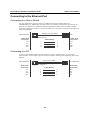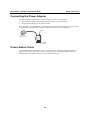
1
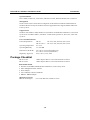
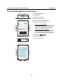
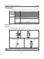
NPort DE-311 Hardware Installation Guide Fourth Edition, June 2008 www.moxa.com/product © 2008 Moxa Inc., all rights reserved. Reproduction without permission is prohibited. NPort DE-311 Hardware Installation Guide The software described in this manual is furnished under a license agreement and may be used only in accordance with the terms of that agreement. Copyright Notice Copyright © 2008 Moxa Inc. All rights reserved. Reproduction without permission is prohibited. Trademarks MOXA is a registered trademark of Moxa Inc. All other trademarks or registered marks in this manual belong to their respective manufacturers. Disclaimer Information in this document is subject to change without notice and does not represent a commitment on the part of Moxa. Moxa provides this document “as is,” without warranty of any kind, either expressed or implied, including, but not limited to, its particular purpose. Moxa reserves the right to make improvements and/or changes to this manual, or to the products and/or the programs described in this manual, at any time. Information provided in this manual is intended to be accurate and reliable. However, Moxa assumes no responsibility for its use, or for any infringements on the rights of third parties that may result from its use. This product might include unintentional technical or typographical errors. Changes are periodically made to the information herein to correct such errors, and these changes are incorporated into new editions of the publication. Technical Support Contact Information www.moxa.com/support Moxa Americas: Toll-free: 1-888-669-2872 Tel: +1-714-528-6777 Fax: +1-714-528-6778 Moxa China (Shanghai office): Toll-free: 800-820-5036 Tel: +86-21-5258-9955 Fax: +86-10-6872-3958 Moxa Europe: Tel: +49-89-3 70 03 99-0 Fax: +49-89-3 70 03 99-99 Moxa Asia-Pacific: Tel: +886-2-8919-1230 Fax: +886-2-8919-1231 Table of Contents Chapter 1 Introduction..............................................................................................1-1 Features .............................................................................................................................. 1-2 Product Specifications........................................................................................................ 1-2 Package Checklist .............................................................................................................. 1-3 Front/Top/Rear/Bottom Panel Views.................................................................................. 1-4 Chapter 2 Overview...................................................................................................2-1 LED Indicators ................................................................................................................... 2-2 Housing .............................................................................................................................. 2-2 DIN Rail.................................................................................................................. 2-2 Wall Mount ............................................................................................................. 2-3 Chapter 3 Serial Installation.....................................................................................3-1 DIP Switch Settings............................................................................................................ 3-2 DB9 Female Connector Pinouts ......................................................................................... 3-2 RS-232 Pinouts ....................................................................................................... 3-2 RS-232 Loopback Tester ........................................................................................ 3-3 RS-422/485 Pinouts ................................................................................................ 3-3 RS-422 Loopback Tester ........................................................................................ 3-3 Mini Adapter........................................................................................................... 3-3 Chapter 4 Ethernet Installation ................................................................................4-1 Connecting to the Ethernet Port ......................................................................................... 4-2 Connecting to a Hub or Switch ............................................................................... 4-2 Connecting to a PC ................................................................................................. 4-2 Chapter 5 Power Connection ...................................................................................5-1 Connecting the Power Adapter........................................................................................... 5-2 Power Status Check............................................................................................................ 5-2 Appendix A Telnet Console........................................................................................ A-1 Opening the Telnet Console .............................................................................................. A-2 Navigating the Telnet Console .......................................................................................... A-2 Main Menu ........................................................................................................................ A-3 serverConfig........................................................................................................... A-3 Serialport................................................................................................................ A-4 Monitor .................................................................................................................. A-4 Ping ........................................................................................................................ A-4 Restart .................................................................................................................... A-4 Exit......................................................................................................................... A-5 Menu Tree ......................................................................................................................... A-5 Appendix B Serial Console......................................................................................... B-1 Appendix C Declaration of Conformity ..................................................................... C-1 1 Chapter 1 Introduction Welcome to Moxa’s NPort Express, a compact palm-sized communications device that allows you to control RS-232/422/485 serial devices over a TCP/IP Ethernet. This chapter is an introduction to the NPort Express and includes the following sections: Features Product Specifications Package Checklist Front/Top/Rear/Bottom Panel Views The NPort Express DE-311 provides a data communications solution for connecting Windows and Linux hosts to asynchronous serial devices over a TCP/IP Ethernet network. Using the NPort Express is like adding a serial port to your PC using a serial board, but with the added advantage of the TCP/IP network. With the NPort Express, Windows hosts can connect to a native serial port and PC-based Linux hosts can connect to a real tty port, all over a network. Virtually any serial device can be attached to the NPort Express to become network accessible, and the network can be configured to allow control of the device from any location in the world. After driver installation, Windows will recognize the serial port on the NPort Express as a real COM port; Linux will recognize the port as a real tty port. The NPort Express provides basic transmit/receive data functions, as well as RTS, CTS, DTR, DSR, and DCD control signals. The NPort Express can be used with your existing applications and comes with a software utility and maintenance wizard. NPort DE-311 Hardware Installation Guide Introduction Features • • • • • • • • 3-in-1 RS-232/422/485 serial interface Auto-detecting 10/100 Mbps Ethernet connection Built-in Ethernet and TCP/IP protocol Compact size for easy integration Supports MAC based IP configuration Supports configuration store and copy for easy deployment Supports Windows Real COM drivers and Linux real TTY drivers Operation modes include TCP Server, TCP Client, UDP Server/Client, Ethernet Modem, and Pair Connection Product Specifications Hardware Processor Memory Connector Interface LAN Serial No. of serial ports Signals Performance Speed Configuration DE-311 DE-311 Rev. 2 16 bit CPU 512 KB DB9 female Auto-detecting 100BaseTX (10/100 Mbps) RS-232/422/485 (DIP switch selectable) 1 RS-232: TxD, RxD, RTS, CTS, DTR, DSR, DCD, GND RS-422: TxD+/-, RxD+/-, RTS+/-, CTS+/-, GND RS-485: Data+/-, GND 50 bps to 230.4 Kbps Parity Data Bits Stop Bits Parity Data Bits Stop Bits None, Even, Odd 7, 8 1, 2 (with parity setting of None) None, Even, Odd, Space, Mark 5, 6, 7, 8 1, 1.5, 2 Supported OS Windows XP, Windows 2000, Windows NT, Windows 95/98/Me Real COM driver, Unix fixed tty driver for UnixWare SVR4.2, UnixWare 7 SVR5, SCO Open Server, SCO Unix, Linux real tty driver Protocols TCP, IP, UDP, Telnet, RTelnet, DHCP, ICMP, BootP 1-2 NPort DE-311 Hardware Installation Guide Introduction Operation Modes Driver Mode, TCP Server, TCP Client, UDP Server/Client, Ethernet Modem, Pair Connection Management Serial console Telnet console NPort Configurator for Windows/Linux Real COM Installer for Windows Monitor Utility for Windows Firmware upgrade function supported NPort Admin for Linux tty driver Supported OS Windows XP, Windows 2000, Windows NT, Windows 95/98/Me Real COM driver, Unix fixed tty driver for UnixWare SVR4.2, UnixWare 7 SVR5, SCO Open Server, SCO Unix, Linux real tty driver Power and Environment Power Requirements DE-311 DE-311 Rev. 2 Operating Temperature 0 to 55°C Operating Humidity 5 to 95% RH Dimensions (W×D×H) Regulatory Approvals DC 9V to 20V, 400 mA (max.) at 9V DC 9V to 30V, 300 mA (max.) at 9V 90 × 100.4 × 22 mm (including ears) 67 × 100.4 × 22 mm (without ears) FCC, CE, UL, CUL, TÜV Package Checklist DE-311/110V DE-311/230V 1 NPort Express DE-311 Universal Serial Device Server 1 NPort Express DE-311 Universal Serial Device Server Both models include • Windows 95/98/ME/NT/2000/XP Real COM driver, Linux real tty driver • NPort Management Suite software • Power adapter • User’s Manual, software CD-ROM • DB9/M – DB9/M adapter Optional Accessories DIN rail mounting kit For 35 mm DIN rail; includes 4 screws 1-3 NPort DE-311 Hardware Installation Guide Introduction Front/Top/Rear/Bottom Panel Views Front Panel View 1. DB9 female serial port 1 ON 1 2 3 2. DIP switches 2 3. DIN rail screw holes 4. Wall mount screw holes Top Panel View DC-IN 5. RJ45 10/100BaseTX Ethernet port RESET 10/100M Ethernet 6. Reset button—hold down for PWR Link 3 a. 3 sec to erase password After 3 sec, the ready LED will flash every twice every second. Release the reset button at this time to erase password. 3 Ready 4 4 3 3 Express b. 10 sec to load factory defaults After 10 sec, the ready LED will flash five times each second. Release the reset button at this time to load factory defaults. DE-311 RS-232/422/485 Device Server Serial SW 7. Power input 8. Rubber base pads Rear Panel View 9. Technical information 7 5 6 Bottom Panel View 8 8 9 8 8 1-4 2 Chapter 2 The following topics are discussed in this chapter: LED Indicators Housing ¾ DIN Rail ¾ Wall Mount Overview NPort DE-311 Hardware Installation Guide Overview LED Indicators The NPort Express’s top panel contains five LED indicators, as described in the following table. LED Name PWR Link LED Color red Power is on off Power is off, or power error condition exists orange 10 Mbps Ethernet connection green 100 Mbps Ethernet connection off Ethernet cable is disconnected, or has a short green Ready LED Function blinking The NPort Server is ready The NPort is requesting an IP address from the DHCP or BootP server. After receiving the IP, the LED will stop blinking. Note: The LED will also blink while holding down the reset button; see page 1-5 for details. off The NPort Server has malfunctioned Housing DIN Rail The DIN rail attachments provide a very convenient installation option for many industrial applications. Installation instructions are as follows: STEP 1: Use the screws to attach the DIN rail mounts to the NPort Express’s ears. ⇒ STEP 2: The two ends of the rail mount are named A and B. Hook the A end over the top edge of the rail. STEP 3: Push the unit against the rail. You should hear the B end clicking into place over the bottom edge of the rail. A A B B NOTE The DIN rail-mounting kit is an optional accessory. 2-2 NPort DE-311 Hardware Installation Guide Overview To remove the NPort Express from the DIN rail, simply reverse Steps 2 and 3 above. Use your fingers to pull down on the B end, which should release the bracket from the rail. Wall Mount Wall installation is another convenient installation option for many industrial applications. Installation instructions are as follows: STEP 1: Obtain two screws with heads no greater than 6.5 mm in diameter and shafts no greater than 3 mm in diameter. At the desired wall location, drive the screws into the wall with 7.8 cm separation between the screws. Do not drive the screws all the way into the wall; leave about 2 mm clearance. 6.5 cm 7.8 cm STEP 2: Hang the NPort Express on the two STEP 3: For added stability, simply tighten the screws using the apertures on the ears, two screws. and then slide the unit downwards. DC-IN RESET 10/100M Ethernet DC-IN PWR PWR Link Link Ready Ready Express Express DE-311 RS-232/422/485 Device Server Serial RESET 10/100M Ethernet DE-311 RS-232/422/485 Device Server SW Serial SW To remove the NPort Express from the wall mount, simply reverse Steps 2 and 3. 2-3 3 Chapter 3 The following topics are discussed in this chapter: DIP Switch Settings DB9 Female Connector Pinouts ¾ RS-232 Pinouts ¾ RS-232 Loopback Tester ¾ RS-422/485 Pinouts ¾ RS-422 Loopback Tester ¾ Mini Adapter Serial Installation NPort DE-311 Hardware Installation Guide Serial Installation DIP Switch Settings The top panel contains a table which describes how to configure the serial port using the three DIP switches. SW1 ON Serial Connection Console (19200,N,8,1) OFF Data Comm. SW2 --OFF OFF ON ON SW3 --OFF ON OFF ON Serial Interface Mode RS-232 RS-232 RS-422 RS-485 by RTS RS-485 ADDC The DIP switches are located on the rear panel. SW1 toggles the serial port between data and console operation (ON or up for serial console operation, and OFF or down for data communication). Data operation is the normal operating mode for controlling serial devices; console operation is for accessing the NPort Express configuration parameters. Note that after modifying SW1 settings, the NPort Express will reboot to initialize the new mode. You must wait a few seconds for the green Ready LED to blink off and then on again, indicating that the function of the serial port has been changed. SW2 and SW3 control the serial port’s data communication interface. Note that RTS stands for Ready to Send and ADDC stands for Automatic Data Direction Control. Keep the following points in mind when setting the DIP switches. • RS-232 Console To use the serial port as a console connection, such as when using Moxa PComm Terminal Emulator or HyperTerminal, set SW1 to the ON position. • Telnet Connection Some configuration may be carried out through a Telnet connection, during which data is transmitted through the NPort Express’s Ethernet port. However, you must set SW1 to the OFF position to establish a Telnet connection. DB9 Female Connector Pinouts RS-232 Pinouts DB9 (Female) 5 4 9 3 8 2 7 1 6 PIN 1 2 3 4 5 6 7 8 9 RS-232 DCD TxD RxD DSR GND DTR CTS RTS --- 3-2 NPort DE-311 Hardware Installation Guide Serial Installation RS-232 Loopback Tester PIN 1 2 Signal DCD TxD 3 RxD 4 5 DSR GND 6 DTR 7 8 CTS RTS RS-422/485 Pinouts DB9 (Female) 5 4 9 3 8 2 7 1 6 PIN 1 2 3 4 5 6 7 8 9 RS-422 RxD-(A) RxD+(B) TxD+(B) TxD-(A) GND CTS-(A) CTS+(B) RTS+(B) RTS-(A) RS-485 ----Data+(B) Data-(A) GND --------- RS-422 Loopback Tester PIN 1 Signal RxD-(A) 2 3 RxD+(B) TxD+(B) 4 TxD-(A) 5 6 GND CTS-(A) 7 CTS+(B) 8 9 RTS+(B) RTS-(A) Mini Adapter The NPort Express DE-311 accepts devices with both male and female connectors. A D-shell female serial connector is built-in, and a DB9 male null-modem adapter is included as a standard accessory. 3-3 NPort DE-311 Hardware Installation Guide Serial Installation If you want to make your own DB9 male to DB9 male null-modem (or crossover) cable, the correct pinouts are as follows: DE-311 s DB9 (Female) DB9 (Male) Null-Modem Mini adapter Device s DB9 (Female) Cable Wiring RS-232 Signals RS-232 Signals DCD TxD RxD DSR GND DTR CTS RTS 1 3 2 6 5 4 8 7 1 2 3 4 5 6 7 8 9 8 7 6 ON 1 2 3 1 2 3 4 5 NOTE PIN 1 2 3 4 5 6 7 8 9 DCD RxD TxD DTR GND DSR RTS CTS RS-232 DCD TxD RxD DSR GND DTR CTS RTS --- RS-422 RxD-(A) RxD+(B) TxD+(B) TxD-(A) GND CTS-(A) CTS+(B) RTS+(B) RTS-(A) The adapter is included with the DE-311 as a standard accessory. 3-4 RS-485 ----Data+(B) Data-(A) GND --------- 4 Chapter 4 Ethernet Installation The following topics are discussed in this chapter: Connecting to the Ethernet Port ¾ Connecting to a Hub or Switch ¾ Connecting to a PC NPort DE-311 Hardware Installation Guide Ethernet Installation Connecting to the Ethernet Port Connecting to a Hub or Switch For most applications, plug one end of your Ethernet cable into the NPort Express’s 10/100BaseTX port, and the other end into a hub or switch that is connected to your network. In this case, you should use a standard straight-through Ethernet cable, which is readily available from many commercial vendors. You may also make your own cable by referring to the following cable wiring diagram. Straight-Through Cable NPort Express RJ45 Jack Connector Tx+ TxRx+ Rx- RJ45 Plug Pin 1 Cable Wiring 1 2 3 6 1 2 3 6 Hub RJ45 Jack Connector Tx+ TxRx+ Rx- Connecting to a PC If you are connecting the NPort Express directly to your PC’s Ethernet port, use a crossover Ethernet cable. You can make your own crossover cable by referring to the following cable wiring diagram. Cross-Over Cable NPort Express RJ45 Jack Connector Tx+ TxRx+ Rx- PC LAN Card RJ45 Plug Pin 1 Cable Wiring 1 2 3 6 3 6 1 2 4-2 RJ45 Jack Connector Rx+ RxTx+ Tx- 5 Chapter 5 Power Connection The following topics are discussed in this chapter: Connecting the Power Adapter Power Status Check NPort DE-311 Hardware Installation Guide Power Connection Connecting the Power Adapter The following steps explain how to connect the NPort Express’s power adapter: 1. 2. Plug the power adapter’s DC plug into the DC-IN jack on the NPort Express. Plug the power adapter into an electrical outlet. Note that there is no on/off switch. The NPort Express will turn on automatically as soon as power is supplied. The red PWR LED will glow to indicate that the unit is receiving power. Ethernet Power to Device Server DC-IN RESET 10/100M Ethernet PWR Link Ready Express DE-311 RS-232/422/485 Device Server Serial SW Female DB9 Connector Power Status Check Use the PWR LED to verify that the unit is receiving power. A red light indicates that power is being received. If the LED is off, no power is being received. If the unit is plugged in and the PWR LED does not light up, there may be a problem with the unit. 5-2 A Appendix A Telnet Console The Telnet console is used to view and modify the unit’s configuration. After installing the unit into a serial device, administrators configure their device remotely by opening a Telnet console session over the network. The following examples refer to a Telnet console session on a Windows 98 host, but the same instructions should apply to all Windows operating systems. The following topics are discussed in this appendix: Opening the Telnet Console Navigating the Telnet Console Main Menu ¾ serverConfig ¾ Serialport ¾ Monitor ¾ Ping ¾ Restart ¾ Exit Menu Tree NPort DE-311 Hardware Installation Guide Telnet Console Opening the Telnet Console A Telnet console session may be opened from the Windows Start menu. Select Start Æ Run... to open a dialog box, and then enter the following: telnet [unit’s IP address] Click OK to begin the Telnet session. At the prompt, enter “1” for ansi/vt100, and then press Enter. The main menu of the unit’s Telnet console will appear as shown. Navigating the Telnet Console Once the Telnet console has been opened, you may navigate through the console using the following keys: • Arrow keys: Use the arrow keys to navigate between different options. If the arrow keys do not respond, you may need to verify your terminal settings by selecting Preferences in the Terminal menu: A-2 NPort DE-311 Hardware Installation Guide Telnet Console Make sure VT100 Arrows under Terminal Options is enabled (checked), and then click OK to return to the Telnet console. • Tab: You may also use the tab key to navigate between different options in the Telnet console. • Enter: Use the Enter key to select the item that is currently highlighted in the Telnet console. Depending on the item, the Enter key may open a submenu, select a field for modification, or perform an action, depending on the item. • Esc: Use the Esc key to cancel a selection or action and return to the previous menu. • Alphanumeric keys: Alphanumeric keys (“A” to “Z” and “0” to “9”) are used when entering certain parameters such as IP address. After making changes to the unit’s configuration in the Telnet console, you will need to save the changes and restart the unit for the new configuration to take effect. Main Menu The main menu displays six categories for configuration: serverConfig, Serialport, Monitor, Ping, Restart, and Exit. Select the desired category and press Enter in order to view and configure the parameters within that category. Each parameter is listed with the parameter name on the left and current setting on the right. Settings that can be modified are displayed in brackets. serverConfig A-3 NPort DE-311 Hardware Installation Guide Telnet Console Serialport Monitor Ping Ping is a standard network testing function that checks to see if a computer with a particular IP address is logged onto the network. Restart This command will save all configuration changes and restart the unit with the new configuration in effect. You must select this option for any changes to go into effect. A-4 NPort DE-311 Hardware Installation Guide Telnet Console Exit This command will discard all configuration changes. The unit will be restarted with its original configuration. Menu Tree The following is a menu tree showing all options available in the Telnet console. Items that are starred are only viewable and cannot be changed by the user: Main Menu serverConfig Server Model* Server Name Serial Number* Operating Mode DHCP Ethernet Status* MAC Address* IP Address Netmask Gateway Remote IP Begin Remote IP End (Slave Only) Password Serialport Port Number* Baud Rate (bps) Parity Data Bit Stop Bit Flow Control Alive timeout(0-99 min) Tx FIFO Monitor Port Number* Tx Char Count* Rx Char Count* Line Status* Baud Rate (bps)* Parity* Data Bit* Stop Bit* Flow Control* Ping exit start to ping target IP address Restart save and restart Exit discard changes and restart A-5 B Appendix B Serial Console The unit supports configuration through the serial console, which is similar to the Telnet console but is accessed through the RS-232 console port rather than through the network. Once you have entered the serial console, the configuration options and instructions are the same as if you were using the Telnet console. The following instructions and screenshots show how to enter the serial console using PComm Terminal Emulator, which is available free of charge as part of the PComm Lite suite. You may use a different terminal emulator utility, but your actual screens and procedures may vary slightly from the following instructions. 1. 2. 3. 4. 5. Make sure the unit is powered off. Use a serial cable to connect the unit’s serial port to your computer’s male RS-232 serial port. Set the SW1 DIP switch on the rear panel to ON for serial console operation. From the Windows desktop select Start Æ All Programs Æ PComm Lite Æ Terminal Emulator. The PComm Terminal Emulator window should appear. From the Port Manager menu, select Open, or simply click the Open icon as shown below: The Property window opens automatically. Select the Communication Parameter tab, and then select the appropriate COM port for the connection (COM1 in the example below). Configure the parameters for 19200, 8, N, 1 (19200 for Baudrate, 8 for Data Bits, None for Parity, and 1 for Stop Bits). NPort DE-311 Hardware Installation Guide 6. 7. Serial Console From the Property window’s Terminal tab, select ANSI or VT100 for Terminal Type and click OK. In the PComm window, you will be prompted for the terminal type. Press 1 for ansi/vt100 and then press ENTER. At this point, the console interface will be identical to the Telnet console. Please refer to Appendix A for details on the configuration options that are available. B-2 C Appendix C Manufacturer’s Name: Manufacturer’s Address: Declaration of Conformity Moxa Technologies Co., Ltd. Fl.4, No.135, Lane 235, Pao-Chiao Rd., Shing Tien City, Taipei, Taiwan, R.O.C. declares that the product: Product Name: Model Number: NPort Express DE-311 conforms to the following standards: EMC: FCC Class B EN55022:1998 class B EN61000-3-2:1995 class B EN61000-3-3:1995 EN55082-1: 1997 EN61000-4-2:1995 Contact Discharge 4 KV, Air Discharge 8 KV EN61000-4-3:1995 EN61000-4-4:1995 AC/DC Power supply 1 KV, Data/Signal lines 5 KV EN61000-4-5:1995 AC/DC Line to Line 1 KV, AC/DC Line to Earth 2 KV EN61000-4-6:1995 EN61000-4-8:1993 3A/m at 50Hz EN61000-4-11:1994 Safety UL/CUL, TUV EN60950