1
Autonomous Targeting
Sentry (ATS)
April 23, 2011
Group 12
Ethan King
Daniel O’Hara
Stephen Rodriguez
James Van Gostein
i
Table of Contents
List of Figures ....................................................................................................................... vii
List of Tables ........................................................................................................................ vii
1.0 Executive Summary ..........................................................................................................1
2.0 Project Description ............................................................................................................2
2.1 Motivation and Goals .....................................................................................................2
2.2 Objectives .....................................................................................................................2
2.3 Requirements and Specifications....................................................................................3
2.3.1 Hardware Requirements ..........................................................................................4
2.3.2 Soft ware Requirements ...........................................................................................4
2.4 Responsibilities of Team Members .................................................................................5
2.4.1 Ethan King..............................................................................................................5
2.4.2 Daniel O’Hara .........................................................................................................5
2.4.3 Stephen Rodriguez .................................................................................................6
2.4.4 James Van Gostein .................................................................................................6
3.0 Research Relat ed to Project Definition ................................................................................6
3.1 Similar Existing Technologies .........................................................................................6
3.2 Similar Senior Design Projects .......................................................................................7
3.3 Possible Architectures and Related Diagrams .................................................................9
3.3.1 The Base ................................................................................................................9
3.3.2 The Gun Mount .......................................................................................................9
3.4 Hardware Research.....................................................................................................10
3.4.1 Microcont roller Research .......................................................................................10
3.4.2 Printed Circuit Board Research ..............................................................................12
3.4.3 Servo Mot ors ........................................................................................................13
3.4.3.1 Motor Control Options .....................................................................................13
3.4.3.2 Servo Control Method .....................................................................................13
3.4.3.3 Open Loop versus Closed Loop .......................................................................14
3.4.3.4 Servo Gear Material ........................................................................................14
3.4.3.5 Digital versus Analog Servos ...........................................................................14
3.4.3.6 Torque Calculation..........................................................................................15
3.4.4 Web Cameras .......................................................................................................17
3.4.5 Alarm Systems......................................................................................................17
3.4.6 Power Sources .....................................................................................................18
3.4.7 Range Det ector.....................................................................................................19
3.4.8 Manual Control Options .........................................................................................20
3.4.9 Manual Controller Communic ations ........................................................................21
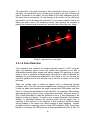
3.4.10 Laser Pointer ......................................................................................................21
3.5 Soft ware Research ......................................................................................................23
ii
3.5.1 Comput er Vision ...................................................................................................23
3.5.1.1 Object Detection.................................................................................................24
3.5.1.2 Object Tracking ..................................................................................................26
3.5.1.3 Motion Tracking..................................................................................................28
3.5.1.4 Color Detection ..................................................................................................29
3.5.1.5 Facial Recognition ..............................................................................................31
3.5.1.6 FPGA or Computer Vision ...................................................................................34
3.5.1 OpenCV ...................................................................................................................35
4.0 Design............................................................................................................................36
4.1 Hardware Design.........................................................................................................36
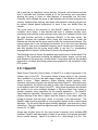
4.1.1 Embedded System ................................................................................................37
4.1.1.1 Microcontroller Selection .................................................................................37
4.1.1.2 Communication ..............................................................................................39
4.1.1.3 Cross Platform Communication: RS232 to UA RT..............................................39
4.1.1.4 Intersystem Communication: I2C .....................................................................41
4.1.1.5 Microcontroller Tasks ......................................................................................41
4.1.1.6 UA RT to I2C Conversion MCU ........................................................................42
4.1.1.7 Servo Motor Control MCU ...............................................................................43
4.1.1.8 Secondary Cont rols MCU................................................................................46
4.1.1.9 Capacitive Touc h MCU ...................................................................................48
4.1.1.10 Laptop and Embedded System Interfacing .....................................................50
4.1.1.11 A TSCOM .....................................................................................................50
4.1.1.12 A TSCA L.......................................................................................................50
4.1.2 Servo Mot or Selection and Acquisition ....................................................................52
4.1.2.1 Servo Motor Specifications ..............................................................................54
4.1.2.2 Servo Motor Implement ation............................................................................55
4.1.3 Base ....................................................................................................................57
4.1.4 Power Source .......................................................................................................58
4.1.5 Alarm system ........................................................................................................59
4.1.6 Web camera .........................................................................................................60
4.1.7 Laser Pointer ........................................................................................................60
4.1.8 Paintball Gun Components ....................................................................................61
4.1.8.1 AirTech E -Matrix Paintball Gun........................................................................61
4.1.8.2 High Pressure Air Tank ...................................................................................62
4.1.8.3 Macrro Line Kit ...............................................................................................63
4.1.8.4 Paintball Hopper system .................................................................................63
4.1.8.5 Paintballs .......................................................................................................63
4.1.9 Printed Circuit Board .............................................................................................63
4.2 Soft ware Design ..........................................................................................................65
4.2.1 Object Detection Class ..........................................................................................67
iii
4.2.2 Motion/Object Tracking Class ................................................................................71
4.2.3 Target ID Class ......................................................................................................73
4.2.4 Trackpoint Class ...................................................................................................74
4.2.5 Turret Class ..........................................................................................................75
4.2.6 Video Capture Class .............................................................................................78
4.2.7 Video Write Class..................................................................................................80
4.2.8 Manual Control Class ............................................................................................82
4.2.9 Facial Detection and Recognition class...................................................................83
4.2.10 Data Structures ...................................................................................................84
4.2.11 Constants ...........................................................................................................85
4.2.12 Software Components .........................................................................................86
4.2.12.1 C++ .............................................................................................................86
4.2.12.2 Visual Studios 2010 ......................................................................................86
4.2.12.3 EagleCAD ....................................................................................................86
4.2.12.4 Code Composer Studio Version 5 ..................................................................86
5.0 Design Summary ............................................................................................................87
5.1 Hardware Design Summary .........................................................................................87
5.2 Soft ware Design Summary ...........................................................................................88
6.0 Prototyping .....................................................................................................................89
7.0 Testing ...........................................................................................................................91
7.1 Hardware Testing ........................................................................................................91
7.1.1 Servo Mot ors ........................................................................................................92
7.1.2 Microcont roller ......................................................................................................94
7.1.2 Power Source .......................................................................................................96
7.1.3 Alarm system ........................................................................................................97
7.1.4 Web camera .........................................................................................................97
7.1.5 Laser Pointer ........................................................................................................98
7.1.6 Capacitive Touch Controller ...................................................................................98
7.2 Soft ware Testing .........................................................................................................99
7.2.1 Color Detection Testing ....................................................................................... 100
7.2.1.1 Detecting the color of a single colored object .................................................. 100
7.2.1.2 Detecting the color of a multi - colored object.................................................. 100
7.2.1.3 Detecting the color of multiple objects in the field of vision simultaneously ........ 101
7.2.2 Object Detection Testing...................................................................................... 101
7.2.2.1 Detecting one object in the field of vision ........................................................ 101
7.2.2.2 Detecting multiple objects in the field of vision ................................................ 101
7.2.2.3 Detecting objects that leave and re-enter the field of vision.............................. 101
7.2.2.4 Detecting objects that are partially occluded from the field of vision .................. 102
7.2.2.5 No objects in the field of vision ...................................................................... 102
7.2.3 Manual Control Testing........................................................................................ 103
iv
7.2.3.1 Rotating the sentry gun left and right .............................................................. 103
7.2.3.2 Panning the sentry gun up and down ............................................................. 103
7.2.3.3 Altering the rate of fire of the sentry gun ......................................................... 103
7.2.3.4 Firing the sentry gun. .................................................................................... 104
7.2.3.5 Alerting the target with a warning ................................................................... 104
7.2.3.6 Alerting the target that the sentry gun is about to attack .................................. 104
7.2.4 Object Tracking Testing ....................................................................................... 105
7.2.4.1 Tracking a single, walking target .................................................................... 105
7.2.4.2 Tracking multiple, walking targets .................................................................. 105
7.2.4.3 Tracking a single, running target .................................................................... 106
7.2.4.4 Tracking multiple, running targets .................................................................. 106
7.2.4.5 Tracking multiple targets with varying velocities .............................................. 106
7.2.4.6 Tracking a high speed object ......................................................................... 107
7.2.4.7 Tracking targets that stop moving for a period of time ..................................... 107
7.2.5 Fire Rate Testing ................................................................................................ 107
7.2.5.1 Single shot ................................................................................................... 107
7.2.5.2 Burst fire ...................................................................................................... 108
7.2.5.3 Automatic fire ............................................................................................... 108
7.2.6 Threat Level Testing............................................................................................ 108
7.2.6.1 A single non-threat target .............................................................................. 108
7.2.6.2 A single threatening target............................................................................. 109
7.2.6.3 Multiple non-threat targets ............................................................................. 109
7.2.6.4 Multiple threatening targets ........................................................................... 109
7.2.6.5 Mix of threatening and non-threat targets ....................................................... 110
7.2.7 Facial Recognition Testing ................................................................................... 110
7.2.7.1 Detecting a Face Using the On-board Computer Camera ................................ 110
7.2.7.2 Matching a Face wit h a Face in the Database ................................................. 111
7.2.8 Integrated Soft ware System Testing ..................................................................... 111
7.2.8.1 One target in the system ............................................................................... 111
7.2.8.2 Multiple Targets in the system ....................................................................... 112
7.2.8.3 Targets entering and leaving the system ........................................................ 112
7.3 Soft ware and Hardware Communication Testing ......................................................... 112
7.3.1 Pitch Servo Motor Communication ....................................................................... 113
7.3.2 Yaw Servo Motor Communication ........................................................................ 113
7.3.3 Trigger Servo Mot or Communication .................................................................... 113
7.3.4 Microcont roller Communication ............................................................................ 114
7.3.5 Web Camera Communication .............................................................................. 114
7.4 Overall System Testing .............................................................................................. 114
7.4.1 Using manual control test the turret’s movement ................................................... 115
7.4.2 Using the object tracking class to detect objects and move the turret accordingly .... 116
v
7.4.3 Battery testing..................................................................................................... 116
7.4.5 Durability testing ................................................................................................. 117
7.4.6 Single target testing............................................................................................. 117
7.4.7 Multiple target testing .......................................................................................... 118
7.5 Environment al Testing ............................................................................................... 119
7.5.1 Indoor testing ...................................................................................................... 119
7.5.2 Outdoor testing ................................................................................................... 119
7.5.3 Dim lighting testing .............................................................................................. 120
8.0 Administrative Content................................................................................................... 120
8.1 Timeline.................................................................................................................... 120
8.1.1 Fall 2011 ............................................................................................................ 120
8.1.2 Spring 2012 ........................................................................................................ 121
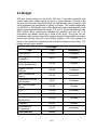
8.2 Budget ...................................................................................................................... 123
9.0 Reflections.................................................................................................................... 124
9.1 Features left out ........................................................................................................ 124
9.2 Future Improvements................................................................................................. 125
10.0 User Manual ............................................................................................................... 127
10.1 Hardware S etup ................................................................................................... 127
10.2 Calibration ........................................................................................................... 127
10.3 Autonomous Mode ............................................................................................... 127
10.4 Manual Controls ................................................................................................... 127
11.0 Works Cited ................................................................................................................ 129
vi
List of Figures
Figure 1 - Result of Object Det ection algorithm .......................................................................26
Figure 2 - Optical Flow of an object ........................................................................................29
Figure 3 - Result of Color Detection .......................................................................................31
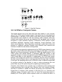
Figure 4 - Haar-like Features .................................................................................................34
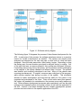
Figure 5 - Hardware block diagram ........................................................................................37
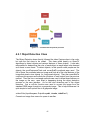
Figure 6 - UA RT to I2C Conversion MCU flow chart ................................................................43
Figure 7 - Servo Motor Control MCU flow chart .......................................................................46
Figure 8 - Secondary Controls MCU flow chart .......................................................................48
Figure 9 - 8 Capacitive Touch MCU flow chart ........................................................................49
Figure 10 - ATS CAL GUI.......................................................................................................51
Figure 11 - Gun and Mount System........................................................................................58
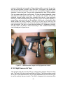
Figure 12 - Paintball marker, hopper, and high pressure air tank ..............................................62
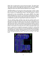
Figure 13 – P rinted Circuit Board Layout ................................................................................64
Figure 14 - Soft ware activity diagram .....................................................................................66
Figure 15 - Soft ware development process .............................................................................67
Figure 16 - Object detection class diagram .............................................................................70
Figure 17 - Motion Tracking class diagram .............................................................................72
Figure 18 - Target class diagram ...........................................................................................74
Figure 19 – TrackPoint class diagram ....................................................................................75
Figure 20 - Turret class diagram ............................................................................................77
Figure 21 - Video Capture class diagram ................................................................................80
Figure 22 - Video Writer class diagram ...................................................................................81
Figure 23 - Manual control class diagram ...............................................................................83
Figure 25 - Facial detection and recognition class diagram ......................................................84
Figure 26 - Prototyping process .............................................................................................90
Figure 27 - Proto Type Model ................................................................................................91
Figure 28 - Testing process ................................................................................................. 100
List of Tables
Table 1 - Comparison of the different Microcontrollers
Table 2 - Dimensions, mass and moments of inertia of moving components
Table 3 - Specifications of Turbo series alarm
Table 4 - Comparison of different laser pointers
Table 5 – MSP430 Microcontroller Comparison
Table 6 – Command codes for communication
Table 7 – Specifications of cross platform communications
Table 8 – I2C Bus specifications
Table 9 - Cost summary of servo motors
Table 10 - Servo Motor Specifications
Table 11 - Error percentages
Table 12 - Angle testing v theory
Table 13 - Fall 2011 Schedule
Table 14 - Spring 2012 Schedule
Table 15 - A TS component planned expenditures
vii
12
16
17
23
38
39
40
41
54
55
92
94
121
122
123
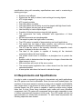
1.0 Executive Summary
In the United States, defense has always been an important factor in the budget.
In 2011, defense attributed for nearly 25% of the U.S. federal budget, more than
any other individual factor.[1] With so much emphasis being placed on defense,
it is evident that a constantly improving defense system is required. Autonomous
sentry guns provide great protection to the area they surround, but do not rely on
the use of people to do so. This aspect is what makes unmanned or
autonomous defense systems such an important field of research.
These
defense systems can be deployed, not only in military settings, but in home
defense, as well. The primary goal of this project is to simulate a realistic
autonomous turret as a defense system to protect a high priority area.
The group’s personal motivation when accepting this project was that it contains
fields from both electrical and computer engineering, providing a comple x task
which challenges the skills obtained throughout our education. Since the
autonomous target sentry gun has many components in which the group
members had limited experience, throughout the process of the project, the
designers learned these technologies in preparation for our future careers.
The key traits to an autonomous sentry gun that make it such a valuable defense
system are reliability, accuracy, intelligence, and efficiency. Reliability is vital
because an autonomous system does not have constant monitoring from a
human, so it must be able to function on its own for long periods of time, without
the risk of component failure. Accuracy and efficiency are major factors because
any targets need to be taken down before they can pose any kind of threat to the
turret itself. Lastly, the system needs to be intelligent so it cannot be bypassed
by someone using a decoy or some sort of distraction.
The objective of the project was to research, design, and prototype an
Autonomous Targeting Sentry (ATS). The turret utilizes knowledge of hardware
components such as servo motors, microcontrollers, capacitive touch sensors,
lasers, web cameras, and printed circuit board design. The system uses the
openCV computer vision libraries to detect, track, a nd eliminate targets. The
turret has the ability to be controlled manually from an application running on the
on-board laptop. The user can take control of the turret at any time to operate the
turret or shutdown the machine.
The turret utilizes two servo motors for pan and tilt of the paintball gun. High
definition web cameras are used in conjecture with openCV to detect and track
enemy targets. When a target enters the field of view of the web camera, the
system begins tracking the target. The target is then warned that they are
entering a restricted zone. The on-board computer continually updates the
targets coordinates while the microcontroller translates coordinates to pulse
widths for the servo motors to move the turret into place. After a second warning
1
to the target, the system begins to fire upon the target until the target exits the
field of view or the system determines the target is no longer a threat.
The team has organized this document to cover the research, design, and testing
of ATS. The research aspect of the project covers several component
comparisons and methods to reaching our objectives and specifications. The
design section will discuss the group’s component decisions and acquisition as
well as detailed software design and implementation. The testing section will
discuss how the team tested individual components, the overall system, and
environmental variables. ATS is an intriguing, challenging and an instructional
project, and the group is proud to show off the final product.
2.0 Project Description
2.1 Motivation and Goals
The motivation behind our project stems from the ever increasing budgets in both
the government and private military sectors. The autonomous turret has many
applications in security, military combat and un-manned vehicles. ATS features a
perfect blend of software and hardware to complement the team’s computer and
software engineers. By incorporating hardware components such as
microcontrollers, servo motors, and capacitive touch sensors ATS tests the
group’s electrical engineering skills; while motion tracking and the onboard
control center allows the groups computer engineers to acquire the skills
necessary for real world software design and development.
The goal of ATS was to incorporate our skills gained over the past four years to
research and design a functional prototype of an automated turret. The prototype
is lightweight and low cost and demonstrates the need and functionality of a real
world automated turret. The system contains intuitive controls and interface so
that anyone can operate and monitor the turret. In order to demonstrate the need
for such a turret the system was designed to be accurate, reliable, and have
quick response times; any lapse in functionality results in massive risk to the
zone ATS is covering.
2.2 Objectives
To ensure the ATS systems meets a stringent quality factor, a system of
specifications was ensured. For our weapon system, high and consistent
accuracy was an objective. For the webcam to properly function with the object
tracking software, a specified maximum resolution was specified. To keep up
with a moving object, the servo motors were able to operate at a specified speed.
In order to limit the amount of fire, the ATS system had specifications for the
firing rate. In order for the tracking software to efficiently track a target, an ideal
time to identify and track a target was specified. The following primary
2
specifications along with secondary specifications were used in constructing a
working prototype.
System is cost efficient
System has the ability to detect, track and target incoming objects
ATS is light weight
ATS is easily portable
The ATS system is reliable
The ATS system has the ability to prioritize targets with high threat levels
The ATS system has easy set-up and usability
Has the ability to track multiple targets
Capable of following targets moving with high speeds
The components are easily accessible with expectations o f future
upgrades
All the components are interchangeable
The weapon system has high levels of accuracy
The ATS system is capable of demonstrating real world applications
The system has two types of alarm systems, one continuous sounding
alarm and an alarm to verbally warn incoming intruders
The ATS has the option to be manually controlled via capacitive touch
sensor, keyboard or an xbox conroller
The base of the system is capable of housing all the electronic
components above the turret system
The printed circuit board is encased in a plexiglass box to protect the
design
System is able to determine when the target is no longer a threat when the
target ceases to move
Microcontrollers will control all the servo motors
The manual control application has a video stream from the turret’s web
camera embedded
A laser pointer aims down the barrel to indicate the target
2.3 Requirements and Specifications
In order to make a successful prototype to demonstrate real world applications,
the ATS system must first be affordable. Since this was a self funded project, the
members of the group wanted to reduce as much cost as possible so affordability
was a major factor in our decision to build the ATS system. With a wide variety of
potential targets, the ATS system is capable of tracking multiple moving targets
either fast or slow. Since many industries push newer and more advanced
components, the ATS system will components that are easily swappable in case
of further improvements throughout its life cycle . The ATS system will also be
well protected by a sturdy base construction. To meet these requirements the
following objectives were created.
3
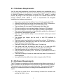
2.3.1 Hardware Requirements
Just like real world applications, specifications needed to be established prior to
any prototyping. This is also the case for the design team; the designers needed
to establish hardware specifications to ensure the ATS system is working
properly. By doing so, the ATS system can prove to be a reliable system that will
produce efficient results. Below is a list of requirements the designers
established as hardware requirements.
The weapon system has the ability to have a hit ratio greater than 50%
Webcam has the ability provide a video stream with 1280 x 720resolution
The entire turret system will weigh no more than 30 pounds
The turret base will not exceed a height greater than three feet
ATS has the ability to cover a lateral angle of tracking of 135 degrees
ATS has the ability to cover a vertical angle of tracking of 90 degrees
The turret is battery operated and has the ability operate for a minimum of
6 hours before a recharge is required
The servo motors has the ability to move at least 4 radians per second
with no load
The paintball gun hopper has the ability to hold 200 paintballs for
ammunition
The alarm system has the ability to be heard from at least 100 feet away
The high pressure aluminum alloy tank has the ability contain 20 oz of
CO2 to pressurize the paintball gun
The barrel of the gun is not be longer than 12 inches long
The system shall has the ability to have a lag of no more than 0.25
seconds upon command via capacitive touch or the onboard laptop
The battery system will not output more than 12 V at any given time
The gun shall has the ability to fire more than 5 paintballs per second in
automatic mode
Turret has the ability to be able to detect and keep track of a minimum of 3
incoming targets
Laser pointer has the ability to be visible on targets within 100 feet
2.3.2 Software Requirements
The ATS system is a compilation of both hardware and software components. A
major component for the hardware to work properly is efficient working software.
The software is the initial step for a working prototype. The requirements below
are a list of software specifications the design team established for the ATS
system.
ATS plays an audio file to warn incoming intruders two seconds after
entering the field of vision.
4
ATS has a response time of less than 0.5 seconds from finding a target to
aligning the gun
A targetID must have 3 or more points to be a valid target.
The object tracking class transmits the coordinates of the target to the
microcontroller with an accuracy of one degree.
A target is deemed no longer a threat when it has 0 velocity (not moving).
The software stream resolution is 640 x 480
ATS software is capable of handling at least 3 targets, simultaneously.
The software determines a 0-target state and give the command to turn off
firing.
The software stores data over the 10 most recent frames
2.4 Responsibilities of Team Members
2.4.1 Ethan King
The roles and responsibilities that Ethan King, electrical engineer, will undertake
are the selection of electrical components including resistors, capacitors,
inductors, operational amplifiers, and voltage regulators. He was also responsible
in choosing servo motors and implemented a embedded system to make sure
each servo motor properly communicates with the microcontroller. Ethan king
was also primarily responsible for the design and implementation of the printed
circuit board with help from James Van'Gostein. Ethan King also worked with
Stephen Rodriquez in programming, designing, implementing, and testing of a
capacitive touch manual controller. Minor responsibilities include assisting Daniel
O’Hara, Stephen Rodriguez, and James Van Gostein with getting the onboard
computer to communicate with the microcontroller controlling each servo motor.
2.4.2 Daniel O’Hara
The roles and responsibilities that Daniel O'Hara, computer engineer, undertook
were mostly on the software side of the project. He was responsible for the
computer vision with the help of James Van Gostein. To be more specific, Daniel
handled the motion tracking, target creation, and target selection. This means
that he was be responsible for the computer vision from the point that the system
receives the image from the camera to where it must make a decision based on if
any objects are tracked. James Van Gostein took the lead on the software
following that part. He is responsible for both the design and documentation of
these algorithms, with the help of the OpenCV software that was used for this
project. Other minor responsibilities included website creation and assistance
with the project hardware as requested.
5
2.4.3 Stephen Rodriguez
The primary roles and responsibilities that Stephen Rodriguez, computer
engineer, were mostly undertake charge of designing and implementing the
power supply. From there, he assisted in servo motors and alarm systems.
Together with Ethan King, he was be responsible for the majority of the hardware
components, this included, the implementation and design of the power sources,
microcontrollers, voltage regulators, alarms, web cameras, servo motors and
architectural structures. Ethan King took the lead on the implementation and
design of the printed circuit board layout and servo motors. Other smaller
responsibilities were to assist both Daniel O’Hara and James Van Gostein in the
software implementation since a large part of this project was software oriented.
2.4.4 James Van Gostein
James a CpE major worked with Daniel O’Hara on the software side of the
project. He assisted in the vision tracking, creation of tracking points and
grouping. James was in charge of the various methods of manual control. James
tested and adjusted the various manual controls so they felt intuitive and easy to
use. James was charged with the building of the base and gun mounting. James
managed the budget and tracked the group’s expenditures as well as logged
meeting times and progress throughout the two semesters.
3.0 Research Related to Project Definition
3.1 Similar Existing Technologies
The ATS system as a whole is not a new technology. Different aspects of the
entire system have previous been done for a variety of reasons, such as the
motion tracking cameras and a gun system that intercepts incoming targets.
These were the original unique technologies that when all integrated together
can help build an autonomous targeting sentry. The influence of these similar
existing technologies has broadened the range for the expansion of the different
prototypes for future optimizations.
The web camera on board the system has had several similar functions in the
past. The web camera for the ATS system is similar to those of any video
surveillance cameras. For example, in banks, the surveillance camera is
continually streaming a video. If the videos need to be replayed, the users can
use facial recognition to identify particular people of interest.
Motion tracking is another similar existing technology. Motion tracking has been
used for several different reasons such as monitoring areas at night and
homeland security. Typically, these cameras have the ability to move on
command. Even in the universities, the instructors have manual control of the
6
cameras for those that record their classes. This is the same for homeland
security, the user can move the directions of the camera to focus in different
areas, and this increases the range of visibility which makes it practical instead of
installing several other cameras.
The military actually has several technologies similar to the ATS system. The
web cameras along with facial recognition and color detection make the ability for
determining friend and foes targets. High tech security systems can include
finger print and retinal scanners, these is to ensure the person of interest is who
they’re supposed to be. To demonstrate this same idea, the designers intend to
have the ability to remotely enable or disable the system when the incoming
target is a friendly. The intention is for only friendly targets have the remote with
a specific password to power down the target, similar to a garage code where
only those who are supposed know will know the correct sequence.
The military actually has a similar system called the Medium Extended Air
Defense System (MEADS). [2] This system is a tri-nationally owned system, the
United States of American, Italy and Germany, and the system is just like the
ATS system. MEADS has the ability to detect and track an incoming missile and
fire its missile to intercept the incoming target. The intent of MEADS is to provide
safety for the city or military base that it is stationed in. Another military
technology that is similar to ATS is the CROWS II gun mounting. The CROWS II
is mounted on top of Humvees and controlled by an operator inside the vehicle.
The system does not automatically track, but ATS’s manual control functionality
has been designed after the CROWS II.
By reflecting on all the similar existing technologies previous demonstrated
successful in the past, the designers of the ATS system integrated several of
them to make a specific design. The system has several functions, mainly as a
defense turret to protect. This system can be further optimized depending on its
use but initially can be used for homeland security and local security for
businesses or home owners. It can even be used in military situations such as
protect a military base from incoming armies and also has the ability to
successfully intercept incoming planes, helicopters, and missiles. The ATS
system’s concept does have several uses, it can protect your possessions or it
can save a life.
3.2 Similar Senior Design Projects
The creation of an autonomous turret system has been successfully completed in
the past. Several other systems have been created, both on a production level,
for sales, and a project level for varies opportunities such as senior design
projects. These projects are related to the ATS system and can be found online
for extensive research. The research of previous project’s successes and failures
aided in designing, prototyping, and testing the ATS system.
7
The idea of creating the ATS system was originally developed by the discovery of
The Sentry Project. This prototype is an automatic targeting paintball gun
intended for purchase for the curious buyers. This was the original inspiration for
creating the ATS system that also consists of a laptop to autonomously control
the servo motors that directs the paintball gun to incoming targets. The ATS
system’s concept is similar to The Sentry Project because it also uses webcameras for of range targeting while continuously streaming video to the laptop
so the user can have the perspective of what the gun see and targets. [3] From
an overview, the ATS system has a lot of similarities to The Sentry Project
however The Sentry Project is business owned and intended for profit. However,
the ATS system’s design varies significantly and the intent of the prototype is to
demonstrate mastery of knowledge instead of profit.
After future investigation into the creating an autonomous gun, it was found that
the University of Central Florida has had several groups create such a prototype
recently for senior design projects. By reviewing previous completed projects, all
the projects have similarities. Of course all the prototypes detect incoming targets
autonomously however; each group used different approaches to reaching this
goal. The group that graduated spring of 2008, created a prototype called the
Paintball Targeting System. [4] This group used color recognition to trace
incoming targets.
Another group that completed their senior design project in the spring of 2009
created the G8 Sentry Gun. [5] This project was unique from the others because
it was able to distinguish between friendly or foe targets. This was done by
implementing GPS positioning. The friendly would carry a mobile device that
would alert the turret that a friendly is entering the targeting zone; those without
this device would automatically be considered a foe.
The final group researched completed their project in the spring of 2011. The
Autonomous Turret, like the others, main purpose systems was to detect, track
and target an incoming intruder. [6] The main difference that separated this
project from previous prototypes is that the designers used an off-board server to
record the video history. This is a very useful implementation for video tracking
for those whose intentions are to recognize the incoming targets. By using an offboard server, the video files are stored in a different location and this will better
equip the owner of the Autonomous Turret to report the intruder to local officials
who can further decide the plan of action to prevent such intrusions.
All of this research has been very helpful for the designers, however; the use of
previous project’s research alone is not sufficient enough to successfully
construct the ATS system from the ground up. Although the ATS does incorporate
some aspects of previous projects it is a very unique project implemented
through the teams own methods. All research completed by previous projects
was merely a spring board that propelled the ATS system to be the most
advanced video tracking systems.
8
The ATS improves upon the color detection algorithm used by the Paintball
Targeting System, and friend/foe detectors used by the G8 Sentry Gun, by going
with an optical flow aglorithm. ATS chose not to incorporate an off-board server to
record the video feed instead the designers intend to make the video tracking
more efficient and not track only by color. Another unique aspect is the ATS has a
capacitive touch remote, keyboard, and xbox360 controller that have the ability to
control the turret remotely, which includes the ability to manually target, initiate
and deactivate the system.
3.3 Possible Architectures and Related Diagrams
3.3.1 The Base
Possible options for the base included creating a tri-pod with a mounting for the
gun at the top. The electronics would be housed in a plexiglass box and be
hooked up to the on-board laptop. This architecture is very similar to a camera
mounted on a tripod. The tri-pod must be sturdy enough to remain standing after
the rapid firing of ATS, if the tri-pod rocks too much ATS’s accuracy would suffer
greatly. This design would raise the gun off of the ground level and allow for
more vertical coverage. The group’s second option was to create a rotating
platform for the gun. This option would require a less complex gun mount but
would be heavier requiring greater torque to get it to turn about. The base would
be composed of the same plexiglass housing which would act as the base while
a rotating plate hooked up to the horizontal servo. The top section would consist
of the gun mount and ammunition. Another option was to create a fixed base with
a pan and tilt system mounted on top to mount the gun. Pan and tilt servos are
commonly used to mount cameras and other lightweight objects. Unfortunately
the pan and tilt system used for cameras only support a maximum of two pounds,
this is not enough to support the gun and ammunition and withstand the recoil of
the gun when firing. The final option was to create a ceiling mounted turret
where all of the components and ammunition could be housed in the ceiling and
out of sight and reach.
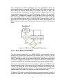
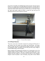
3.3.2 The Gun Mount
Creating a lightweight durable gun mount was a major design challenge the
group faces. The gun mount must be very strong to hold up to the vibration and
stress of the automatic firing rate. If the gun mount is too heavy the servo motors
would have a hard time rotating the gun, but if the mount is too light there is a
chance it would break or severely decrease the accuracy of ATS. The group has
a few different options for mounting the paintball gun. The first option is to create
a frame for the gun to rest in. This can be done by creating a box made of
lightweight metal rods. The rods support the barrel and the handle of the gun.
Two more metal rods would be used to keep the gun straight and accurate. The
second option the group is considering is a side mounting for the gun. The mount
would be positioned on the left or right side of the gun and have the ability to
9
swivel left, right, up and down. This is very similar to the system used by the
paintballsentry project the group has researched online. [3] This mounting would
be very lightweight and keep the sentry compact and offer a less cumbersome
mounting. The pan and tilt option required that the group builds a platform to rest
the gun on, unlike the camera pan and tilt option the groups platform must
support more than two pounds.
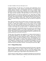
3.4 Hardware Research
3.4.1 Microcontroller Research
A microcontroller is an integrated chip that has a wide variety of functions that
enable them to provide unique control to a specific design. This is different from a
microprocessor, which is a multifunctional chip that completes a variety of tasks.
Therefore, a microcontroller is intended to be more self-contained and dedicated
to specific tasks. Microcontrollers have the ability to execute a set of stored
instructions capable of out tasks defined by the designer. Micro-controllers also
have the ability to access external memory chips and read/write data to and from
the memory. Microcontrollers consist of a processor core, memory and
programmable input/output peripherals. In its entirety, a microcontroller is
essentially a basic computer in a single integrated circuit.
There are a variety of the microcontroller designs available for completing the
necessities for the ATS system; however, there are 3 main options that are
sufficient for the design requirements. Each microcontroller has its advantages
and disadvantages. The first option for a possible microcontroller is the
PIC16F1503, Peripheral Interface Controller, from Microchip Technologies Inc.
[7] These microcontrollers have the Harvard architecture – in which instructions
and data come from separate sources. This simplifies the timing and design
which helps optimize clock speed and power consumption. These
microprocessors have RISC architecture, a built in oscillator with adjustable
speeds and a wide range of interfaces with free Integrated Development
Environment and several commercial compilers available for the designer. The
disadvantages for these microcontrollers are that it is an older design but it is a
simple and powerful architecture. These microcontrollers only have one
accumulator and operations and registers are not orthogonal, meaning some
instructions can only use the accumulator, while others can only address the
RAM and/or immediate constraints. However, for the necessities of the system,
these constraints should not be a problem for overall design of ATS.
Another main consideration for selecting the PIC family of microcontrollers is the
programming language. These microcontrollers are provided with a free
assembler package with Microchip MPLAB Integrated Development
Environment. It can also be programmed at higher levels of programming such
as C. Free C compilers are also available as well as low-cost development tools
depending on the preference of the designer. Both are offered in design support
10
from Microchip and have a technical support and training available twenty four
hours a day, seven days a week.
The second option is the MSP430F5172 from Texas Instruments. [8] These
microcontrollers are 16-bit and RISC based but the stand out advantage of the
MSP430F5172 microcontroller is that is designed specifically for ultra-low-power
consumption. This is a major advantage because the MSP430F5172’s
peripherals enable ultra-low-power optimization which could ultimately extend
battery life. This feature validates TI’s competition amongst the leading
microcontroller distributors. TI’s integrated communication peripherals and highperformance analog make this microcontroller a great option for controlling servo
motors that is a key component in the system design. These 16 bit chips range
from 1KB to 256KB of flash memory. Another advantage for this microprocessor
is the TI Launchpad development board kit.
The MSP430F5172, like the PIC, can be programmed in a high level like C with
Code Composer Studio. There is also an alternative C compiler which could have
served as an efficient multi-platform compiler called mspgcc. This is a free and
unlimited C compiler for TI’s MSP430 series of microcontrollers. The MSP430
microcontrollers also have online training, tools and software to help support the
designer.
The last option of microcontroller manufacturers to consider is Atmel Corporation.
For the ATS system to be optimal with a minimum response time, simple
calculations from the microcontroller need to be performed efficiently to reduce
the lag time of targeting the incoming intruder. One of the perks of choosing an
Atmel’s SAM9 product line is this particular line is designed for high speed
processing. With the line chip performing at approximately 240 MHz, this makes
this microcontroller more than efficient for computing the simple calculations
needed for the ATS system. [9] The major setback of choosing this
microcontroller is it is much larger and consumes more power than smal ler
microcontrollers that are equally capable of completing the tasks needed for the
ATS system. So this makes it a more expensive microcontroller needed for the
application. So even though this microcontroller series is designed for high speed
processing, it doesn’t appear to be a necessity for the ATS system to perform
sufficiently.
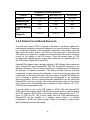
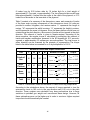
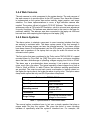
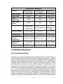
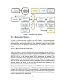
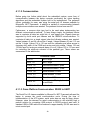
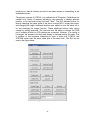
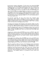
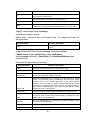
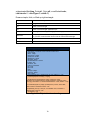
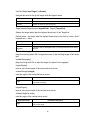
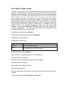
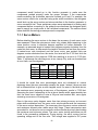
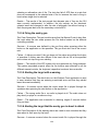
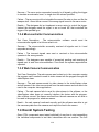
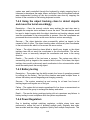
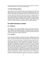
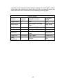
Table 1 contains the three different microcontrollers the designers intended to
use. The key differences to note are the comparison in number of pins as well as
the program memory. The designers of the ATS systems do not need an
excessive amount of pins or a large memory, so the designers intend to
implement Microchip’s PIC16F1503.
11
Comparison of microcontrollers
Product
Developer
Number of Pins
Memory Type
Program Memory
(KB)
Operating
Voltage (V)
SAM3S1A
MSP430F5172
PIC16F1503
Atmel Corporation
Texas Instruments
Microchip
48
29
14
Flash
Flash
Flash
64
32
3.5
1.62 to 3.6
1.8 to 3.6
1.8 to 5.5
Table 1 - Comparison of the different Microcontrollers
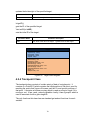
3.4.2 Printed Circuit Board Research
A printed circuit board (PCB) is typically a flat plate of insulating material that
interconnects electronic components designed for a specific purpose. Connected
by a conductive material, these electronic components have unique functions
that control the device. And so, the PCB is a key component in controlling the
ATS system as a whole for it contains the microcontrollers that control the servo
motors for the mobility of the ATS system. There are several types of PCB
manufacturers available but two options were looked into for implementation for
the ATS system, ExpressPCB and 4PCB.
ExpressPCB provides a free, designer assisting, CAD software that includes two
parts, ExpressSCH and ExpressPCB. [10] The ExpressSCH program is for
drawing schematics. This is to begin the process of designing and to familiarize
the designer of drawing schematics. The library provides common electrical
components so when drawing the schematic; it can be as simple as placing the
components on the page and wiring the pins together. ExpressPCB allows the
user to develop a printed circuit board that corresponds to the schematic
previously created. This is a possible because ExpressSCH can be linked with
ExpressPCB to ensure continuity. This makes laying down traces for the printed
circuit board easier. ExpressPCB has a package of three identical 3.8” x 2.5”
PCB that can be purchased for $51.
A second option to use for the ATS system is 4PCB. [11] Like ExpressPCB,
4PBC offers free software called PCB Artist with tutorial videos to help the design
the PCB. However, 4PCB offers a 60 square inches, approximately an 8” x 7”
piece, of PCB for $33. This is much larger than the PCB manufactured by
ExpressPCB but the benefits of a cheaper option makes it a definite
consideration. 4PCB also allows student buyers to purchase a single board
which ultimately benefitted the budget.
12
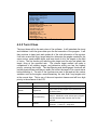
3.4.3 Servo Motors
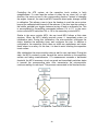
3.4.3.1 Motor Control Options
To effectively control the autonomous turret, a system of motors was
implemented to allow for full motion and firing. Since the turret is designed to be
stationary, it is best to think of the turret as the origin of a spherical coordinate
system. This allowed one motor to be dedicated to the yaw direction, a second
motor dedicated to the pitch direction and a third motor could be dedicated to
pulling the trigger
Since the turret remained stationary at the origin, rotational motors provided the
easiest control. There are two types of motors that primarily stand out. These
choices are a standard DC motor and a signal controlled servo motor, both of
which have their own advantages and disadvantages.
Advantages to the DC motor include a full 360 degree range of motion, one input,
and the availability of high torque. However there are large drawbacks when
used in a controls environment. The largest of these drawbacks is the low
precision. The motor is either on or off where speed can be adjusted based on
the input. In order to accurately co ntrol the position a highly accurate
microcontroller was most likely needed. Another large drawback is the significant
cost of higher torque motors.
Advantages to the signal controlled servos include a lower cost when compared
to DC motors, a signal controlled position, and multiple similarly previous projects
to be the starting point of research. Like DC motors, the signal controlled servos
has drawbacks. The largest drawback to servo motors is quickly increasing cost
for the increase in torque. Another la rge drawback is that most stock servo
motors only have a 90 degree range of motion. In order to gain a 180 degree
range of motion additional charges may apply.
In order to keep the cost low and simplicity high, servo motors were chosen to
control the yaw and pitch directions of the turret. For pulling the trigger, a low
cost, low torque servo can be utilized.
3.4.3.2 Servo Control Method
Most standard servos have three leads, positive power, negative, and signal. The
power lead not only acts as the power so urce for the servo, but can also be
utilized to turn the servo either on or off. The typical input voltage for power is
between 4.8 volts and 6.0 volts. The negative power lead should be common
ground. The signal lead controlled the direction of the servo.
The primary method of controlling the servo is to send a pulse-width modulation
signals along the signal lead. This pulse -width modulation signals is a fifty hertz
square wave. The length of each pulse of the square wave controls how far the
13
servo will rotate. For example a pulse of 600 microseconds will rotate the servo
arm -90 degrees and a 2400 microsecond pulse will rotate the arm positive 90
degrees. [12]
3.4.3.3 Open Loop versus Closed Loop
For a servo motor, there is a significant difference in an open loop and closed
loop control system. In an open loop control servo control system, the pulse
widths control how far the servo rotates in a specified amount of time. In other
words, the length of the pulse width modulation controls how fast the servo
rotates, not the position. For example, a 600 microsecond pulse may rotate the
servo 90 degrees counter-clockwise in 0.15 seconds while a 1000 microsecond
pulse may rotate the servo 45 degrees counter-clockwise in the same 0.15
seconds.
In a close loop servo control system, the length of each pulse controls the
position, instead of how fast the servo rotates. For example a 600 microsecond
pulse may rotate the servo to the 90 degrees counter-clockwise position in 0.15
seconds while a 1000 microsecond pulse may rotate the servo to the 45 degree
counter-clockwise position in 0.075 microseconds.
Most standard servo motors can only rotate 90 degrees and can be stretched to
180 degrees for an additional cost. These rotational limitations are placed by a
potentiometer built into the servo motor. As the potentiometer rotates with the
servo, the voltage across the potentiometer changes allowing this voltage
change to be used for feedback to control the position. The potentiometer can be
disconnected to achieve a full 360 degree continuous rotation, however the
feedback to control the position is lost and an external circuit would have been
required. Since it was specified that the turret rotates below 180 degrees, a
continuous rotation is unneeded; this allows for the utilization of the built in
closed loop system. [13].
3.4.3.4 Servo Gear Material
There are four major gear materials used in servo motors. Nylon is in the lowest
tier of gear material is generally the most common in stock servos. Karbonite is
slightly above nylon in strength and durability and also runs quieter than Nylon.
Metal gears are stronger than karbonite but have lower durability. Titanium gear
is the highest tier of gear material. Titanium gears provide extremely high
strength and durability, but at a significantly higher cost. These different gears
can be purchased and swapped in as needed, however gear sets for each
material do not exist for every servo combination.
3.4.3.5 Digital versus Analog Servos
Like many components in the electronics world, servo motors come in standard
analog and digital varieties. Functionally speaking, a digital servo is a standard
14
analog motor with a built in microprocessor that analyzes incoming signals to
control the motor. Digital servos have two distinct advantages over their analog
counter parts. With the built in microprocessor, the servo performance can be
better optimized depending on servos function. Also because of the built in
microprocessor, the pulse width modulation sent from the microprocessor
operates at a higher frequency than the standard 50 Hz used for analog servos.
This leads to higher accuracy, smoother acceleration, and the availability to hold
higher torque. However, because of the addition of the microprocessor the servo
comes with disadvantages. Since the digital servo operates at a higher frequency
for higher accuracy, the power consumption also increases. The price of digital
servos is also significantly higher than their analog counter parts. [13]
3.4.3.6 Torque Calculation
In order to calculate the required torque needed for the servo motors, the angular
torque formula must be utilized.
The approximate weight of an unloaded paintball gun used as references was
2.25 pounds, or approximately 1.134 kilograms. The maximum allowed weight for
one paintball gun is 3.5 grams, or 0.0035 kilograms. It assumed that 100
paintball guns will be loaded into the hopper for a weight of 0.350 kilograms. A
lightweight paintball gun hopper, the component that holds, the paintball gun
ammo, is advertised as approximately one pound. Since paintball gun hoppers
vary largely, it was assumed the hopper weighed two pounds, or approximately
0.9072 kilograms. The total mass of the paintball gun, pai ntballs, and hopper, is
approximately 2.392 kilograms. For simplicity, this mass of a loaded paintball gun
is estimated to 2.500 kilograms. The length dimensions of the paintball gun are
estimated to be 24 inches long by 3 inches wide by 8 inches high. For simplicity,
the paintball gun was assumed to be a cuboid. The moment of inertia must be
calculated across two axis, the pitch and the yaw. The calculations can be found
in table 2.
It was assumed that the base platform would have been constructed of quarterinch plywood. According to the APA plywood specifications, 0.842 inch thickness
of unsanded plywood weighs approximately 3 pounds per square foot. [14]
Quarter-inch plywood can be estimated to be .75 pounds per square foot, which
is also a rule of thumb. Assuming the base platform is 24 inches by 24 inches, or
0.6 meters by 0.6 meters, of half inch-plywood, the approximate is estimated to
be 3 pounds, or approximately 1.5 kilograms. Similar to the paintball gun, the
base platform moments of inertia are calculated in table 2.
The base tower holding the paintball gun was assumed to be constructed of
quarter-inch unsanded plywood. As previously used, quarter-inch plywood can be
estimated to 0.75 pounds per square foot. It was assumed that the base tower
compose of two quarter-inch plywood slabs that would have been approximately
15
8 inches long by 0.25 inches wide by 16 inches high for a total weight of
approximately 1.5 pounds, or approximately. The two plywood slabs would have
been placed parallel, 4 inches from the center to the outer of the plywood, or 3.75
inches from the center to the inner side of the plywood.
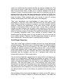
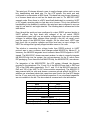
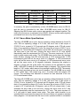
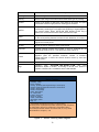
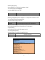
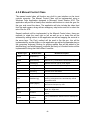
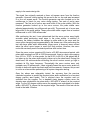
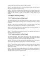
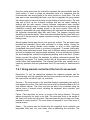
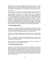
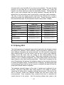
Table 2 consists of a summary of the dimensions, mass, and moments of inertia
of the three major moving components of the autonomous turret. All units are
provided in meters, kilograms, and newton-meters. “L” represents the length in
meters, “W” represents the width in meters, “H” represents the height in meters,
and M represents the mass in kilograms. Since the base platform would have not
rotated along the pitch direction, the moment of inertia can be ignored in the pitch
direction. The moment of inertia is given in Newton-meters. According to the
above equation, the angular torque is calculated by multiplying the moment of
inertia and angular acceleration, assumed to be 60 degrees per 0.15 secondssquared or approximately 6.9 radians per seconds-squared. The total torque in
either direction can be summed by the principle of superposition The torque
listed in the table below is converted to oz-in by multiplication of 141.6.
Moment of inertia and torque calculations
Part
L
W
H
M
Paintball
Gun
.61
.08
.20
2.5
Base
Platform
.61
.61
.006
1.5
Base
Tower
.20
.006
.41
0.7
Total
NA
NA
NA
NA
Moment of Inertia
Torque
NA
Table 2 - Dimensions, mass and moments of inertia of moving components
According to the calculations above, the amount of torque required to turn the
autonomous turret in 182 oz-in in the yaw direction and 91.5 oz-in in the pitch
direction. These numbers are calculated from heavy estimations due to large
variations in paintball gun weight and unconfirmed base design. However, all
these estimations were on the higher end in order to receive a higher required
torque that should theoretically be needed.
16
3.4.4 Web Cameras
The web camera is a vital component in the system design. The sole purpose of
the web camera is to provide optics for the ATS system, from there the software
is implemented so the system has motion tracking, target creation, and target
selection. For these implementations to occur, a high definition camera was
needed. The system utilized a Logitech C310 HD Webcam. The webcam has a
widescreen video at 720 pixels HD Resolution, a built-in mic and auto adjustment
for poorly lit settings. The webcam was attached next to the turret on the base for
maximum stability. The webcam was also connected to the laptop via USB and
has real-time video capturing that displays on the laptop. [15]
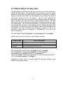
3.4.5 Alarm Systems
The alarm system is strategic component to warn incoming intruders that they
are entering a restricted area. The alarm system needs to be loud enough to
ensure the incoming targets can hear the potential warning. Two alarm options
have been chosen to be implemented onto the ATS system, a continuous audible
alarm and a speakers of the laptop that can play an audio file stored on the
onboard control system.
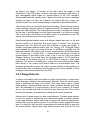
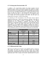
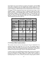
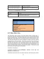
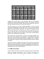
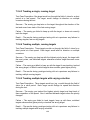
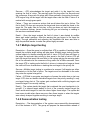
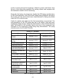
The first option that was considered is the Turbo series TMC-86-530-W, a panel
mounted alarm by Floyd Bell Inc. [16] This option was a continuous sounding
alarm that has a wide arrange of operating voltages ranging from 5Vdc to 30Vdc.
The alarm was a non-descriptive alarm meaning it just outputs a continuous
noise, much like a fire alarm. The typical operating current ranges from 2mA at
5Vdc to 10mA at 30Vdc. In table 3 below, the important working specifications
are provided. The output sound and current consumption is linearly related, so
the higher the input current, the louder the ala rm is going to be. This option was a
cheap viable option that only cost $9.64 per alarm component.
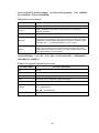
Turbo series TMC-86-530-W
Mounting
Panel Mounted
Operating mode
Loud – Continuous
Operating current
2mA at 5 Vdc
10 mA at 30 Vdc
Termination
Wires
20% over the maximum rated
voltage for five minutes
Table 3 - Specifications of Turbo series alarm
Surge Voltage
The second option considered was to just use a simple speaker that plays a
unique audio file from the system. This gives the option to warn incoming
intruders of specifically what the system’s intentions are. For example, the
17
system can verbally warn the intruders that they are entering a danger zone. This
option gives a variety of audio files to instruct the intruder to exit the area and
warn of an imminent attack. A basic set of computer speakers such as the
Insignia 2.0 Stereo Computer Speaker System was to be a satisfactory option for
the necessity of the system and these speakers are available for $19.99 from
Best Buy. [17] However, the ATS designers decided to just use the speakers on
board the laptop. These speakers were loud enough to warn off incoming
intruders while playing custom audio file chosen by the designers.
There were advantages and disadvantages to using either option. The
advantages of using the Turbo series TMC-86-530-W has the ability perform
better outdoors because its casing is resistant to salt spray, humidity, dust and
vibrations. However, the disadvantage is the alarm cannot inform incoming
intruders of the system’s intent to fire upon them. It more likely to startle the
intruders but these intruders may not have a clear instructions of what the ATS
system intends to do. The major advantage of using the speakers that read an
audio file from the computer is the alarm can verbally alert intruder that they are
in a potentially dangerous zone if they continue to proceed forward. The
disadvantages are the alarm does not have the ability to be as loud and will not
be as outdoor resistant. Therefore, the ATS design team decided to use both
alarm components to serve the purpose of alerting incoming intruders.
3.4.6 Power Sources
There was a wide range of batteries available and each has certain advantages
and disadvantages. The different types of batteries range from Alkaline batteries
to lithium- ion batteries but for the purpose of the ATS system, the designers
narrowed the choices of batteries to two viable options, lead - acid and nickelmetal-hydride batteries. Both of these types of batteries are matured and have
proven quite reliable in the past. Therefore, there was a wide range of previous
knowledge that the designers can turn too if problems arise during the
implementation process of either power source.
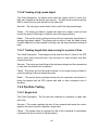
First, the lead-acid batteries, typically known for being used as car batteries, are
used for a lot of applications. CSB Battery technologies Inc. builds a 12V/1.3Ah
Sealed Lead Acid battery available at RadioShack for 15.99.[18] This is a smaller
version of a typical car battery so the size was not to be a problem for the ATS
application. The lead acid battery has a an extremely high boiling point,
temperatures far higher than the system was to ever experience and the battery
was known to be very easy to work with. Under normal operating conditions, the
internal material is not be hazardous, only if the battery is exposure or leakage of
the internal material occurs, is the battery be hazardous but exposure is very
unlikely.
One advantage of this is how small this battery is in relation to the ATS system. It
has a length of 3.8 inches, a height of 2.05 inches and width of 1.89 inches and
18
the battery only weighs 1.3 pounds so this didn't affect the weight or size
dimensions of the ATS system. However, the major advantage is this battery is
also rechargeable which makes an optimal battery for the ATS designers.
Rechargeable batteries typically have a higher initial cost but can be recharged
cheaply and used over and over. Therefore, the battery will have a lower total
and also benefit from environmental damage compared to disposable batteries.
The second option, was the nickel metal hydride battery. These batteries work by
using a hydrogen absorbing alloy for negative electrode This makes the capacity
larger than other batteries. The energy density is similar to a lithium-ion battery,
but the rate of self-discharge is much higher compared to a lithium-ion battery.
This is one reason the lithium-ion batteries were not considered for the ATS
system, because they tend to be every expensive.
Nickel-metal-hydride batteries come in all different shapes and sizes, so the next
decision would be to determine how much power is needed. The designers
determined that 12V would be more than sufficient to power the system. A
suitable nickel-metal-hydride battery was the Tenergy 12V 1400mAh battery
pack available through total power solutions on All-Bettery.com.[19] Like the
lead-acid batteries, this battery pack is small, actually smaller with the dimension
of 2.3 inches long, 1.3 inches wide, 1.1 inches tall and only weighs 8 ounces. A
special feature of this battery pack is that it has a long life cycle and rapidly
charges. However, the original intent for this battery pack is for RC aircrafts or
mini Robots so the battery pack has 16 AWG Wires to connect to these usual
platforms. This makes it a challenge to connect the nickel-metal-hydride battery
pack directly to the printed circuit board where the microcontroller were . The
designers will be able to splice the wires to connect directly to the printed circuit
board but then has to determine how the battery pack will be capable of being
recharged once connected directly to the PCB..
3.4.7 Range Detector
In order to accurately predict the location an object to be tracked, a range sensor
would have been needed to be implemented. Naturally, there are various sensor
types to determine the range of an object. One range sensor type is infrared
range sensors. Typically infrared sensors cannot measure distance past thirty
feet. The advantage to IR range sensors is the low price. However, IR sensors
are not very accurate and tend to be limited to less than thirty feet. This is much
less than the desired one-hundred feet making the IR sensor impractical.
Another type of range sensor is a laser range detector. The laser range detector
is used in a variety of applications from recreational sports to military defense.
Laser range detectors have a wide band of ranges well within the desired onehundred feet and are highly accurate. Even though a laser rangefinder would
work, it is difficult to find one with a reasonable price and the ability to work with
the microcontroller. Typical laser range detector prices start around $100 and
19
exceed the $1000 mark.
Another type of range sensor is an ultrasonic range detector. Like the laser range
detector, the ultrasonic has a wide band of ranges within the desired onehundred feet. Ultrasonic range detectors are typically cheaper than the typical
laser range detector. However, unlike the laser range detector, the ultra-sonic
range detector is typically inaccurate and could have had issues detecting the
distance when multiple objects are moving.
Of these options, the best and only reliable range detection sensor typical would
have been the laser range detection. However, for a starting price of
approximately $100 and difficulty of incorporating said sensor with a
microcontroller, the options of not having range detection was considered. Ideally
the ATS system is in a relatively small confined space smaller than 100 feet by
100 feet. The average paintball gun should theoretically fire straight pass 100
feet. Although the turret is not able to predict the location of the tracked object, it
should was still able to predict the direction of the tracked object. Although a
range detector would have been a great advantage for the autonomous turret to
have, the cost is not justified since the direction of a n object and already be
predicted. Thus, no range detector was implemented.
3.4.8 Manual Control Options
There are multiple methods of manual control for the autonomous turret. One
method is to develop a website that offers a full control of the turret. This custom
website would have options to control the pitch, yaw, and firing rate via a custom
built GUI. The advantage to having a custom website is the easy expansion of
various options. A video feed from the web cameras, preset firing rates, and
accessibility to mobile devices are a few examples that could be implemented.
The disadvantage to the having a custom built website is the need for a
secondary computer to host a server and the need for additional networking
hardware.
There are also multiple methods to control the servo motors with a physical
“handheld’ controller. One method was to purchase a pre-built servo motor
joystick controller from servocity.com. A two servo joystick controller from
servocity.com currently cost $99.99. The advantage to this controller is no
additional need for another circuit design. Power gets plugged directly into the
controller and the controller outputs operating voltage power, ground, and signal.
The disadvantage is the ridiculous cost for plastic and wiring, and the complete
bypass of the microcontroller controlling the servo motor position and firing.
With the increase popularity of capacitive touch devices, an updated controller
replacing the joysticks with a capacitive touch controller makes an interesting
controller. One advantage to building a custom capacitive touch controller is the
ability to design the controller to work cooperatively with the position and trigger
microcontroller at a much lower cost. Another advantage is the possibility to
20
incorporate custom modifications including predefined settings, custom firing
rates, and a current position display. The main disadvantages are the huge step
in difficulty and the need for an additional microcontroller.
A large deciding factor in choosing manual control method was cost. According to
the Texas Instruments website, a capacitive touch booster pack with a MSP430
microcontroller Launchpad costs roughly $15.00. The MSP430 microcontroller
and booster pack combination was chosen since the group is already somewhat
familiar with the product. When compared to the prebuilt two servo joystick
controller from servocity.com, the clear winner is a custom built capacitive touch
controller. In addition to the capacitive touch controller, the turret has the ability to
be controlled by the on-board keyboard and xbox360 wireless controller.
3.4.9 Manual Controller Communications
With the selection of a capacitive touch controller, a method of communication
between the position and trigger microcontroller and the capacitive touch
controller must be incorporated. There are three primary methods of are onboard,
wired, and wireless.
The easiest method of communicating between the two microcontrollers is simply
building the capacitive touch controller directly onto the turret. The capacitive
touch controller would have simply be attached to the turret, translate the
capacitive touch to pitch and yaw degrees, and then send this information to the
microcontroller controller the servo motors. The servo microcontroller simply
translates the pitch and yaw degrees to the correct pulse width modulation.
Although it is possible to transmit data over a wired or wireless connection, the
difficulty of implementing a wired or wireless connection within a semester
timeline may have been difficult since the difficulty of implementing a real world
capacitive touch controller was largely unknown. The microcontroller
implemented with the capacitive touch controller was programmed heavily with
functions in order have the communication and calculations separate.
3.4.10 Laser Pointer
A laser pointer was another component the designers wished to implement to the
ATS system so the users can visually see where the gun was pointing at.
However, there is a wide range of laser pointers to choose from but the typical
distinction between each other is the laser color. The color of the laser is based
off of the wavelength intervals from the visible light spectrum. The designers
narrowed the options down to three different options, a red, a green and a blueviolet laser pointer.
The first laser pointer was the red laser pointer, with a wavelength interval
between 635 – 700 nm. [20] The red laser pointer pen from LasersMan.com
actually outputs 5mW of power and has a wavelength of 650nm. But since the
21
red laser point was one of the original laser pointer technologies and the growth
of technology, the red laser pointers have no longer become a first choice option.
The laser pointers lack the power and distance of new models but are still a
cheap viable option, especially for simple uses likes pointing at a projector for
presentations. Since the red laser pointer lacks the distance factor, the designers
opted not to use this design. [21]
The next option was the blue-violet laser point. With a wavelength interval
between 400 – 490 nm, the blue-violet color is on the opposite end of the visible
light spectrum. [20] This laser is still a new cutting edge technology, and has only
recently been available in the market, mainly known for the creation of the bluray, high definition video technology. LaserPointPro.com has a adjust focus blueviolet laser pointer pen that has a larger range than the red laser pointer, which
would benefit the system for targeting the incoming targets further away. [22]
Although the laser pointer is a new technology, it is also an expensive one,
costing $73.99. So the designers of the system decided there is no need to
impact their budget to meet the requirements that other laser pointers can
achieve.
The final option was the green laser pointer. With a wavelength interval between
490 – 560 nm, the green color is right in the middle of the visible light spectrum.
[20] Today, this laser pointer is far brighter than red lasers. Known for such long
ranges, it has actually become a felony for individuals that would aim green
lasers at planes flying for distracting the pilots. LaserPointPro.com has a midopen green laser pointer available that has a wavelength of 532nm and operates
at 3-4.2 volts. [23] So the designers decided the mid-open green laser pointer
because it was more than sufficient enough to demonstrate compliance for the
system.
In table 4 below, there is a comparison chart of the three different lasers the
designers initially considered to use. The key things to note are the laser
wavelength, laser range, and cost. The laser wavelength was what determines
the color and range. As you can see by the range comparison, the green and
blue-violet laser pointers are significantly larger than that of the red laser pointer.
After that, the cost was the determining factor, and since the mid-open green
laser pointer was significantly cheaper, the designers chose to use this model.
22
Laser Pointer Comparison
Product
Mid-open Green
Laser Pointer
Red Laser Pointer
Pen White
Adjust focus
Laser Pointer
HK-E03358
A0877000AV0107
HK-E03508
Laser Color
Green
Red
Blue-violet
Laser
Wavelength
532nm
650nm
405nm
Laser output
power
20mW
5mW
150mW
2 x LR03 AAA
1.5V batteries
2 x AAA batteries
1 x 18650
2200mAh 3.7V
battery
3.0 – 4.2 volts
3.0 volts
3.0 – 4.2 volts
Continuous Wave
Constant wave
Constant wave
1.295 x 14.198
1.27 x 13.716
2.2 x 14.3
500 – 5000
Approx. 1600
500 – 5000
Model number
Power Supply
Working Voltage
Working Mode
Dimensions (Dia.
x L) in
centimeters
Laser Range
(meters)
Cost
$14.99
$3.39
Table 4 - Comparison of different laser pointers
$73.99
3.5 Software Research
3.5.1 Computer Vision
Computer vision is an increasingly popular application and has a wide variety of
uses. Computer vision has found its way into robotics, surveillance, defense
systems, and other applications. The process of computer vision is generally the
same for all applications with variances for each specific use. The usual steps of
computer vision software follow the pattern of image processing, object
detection, object tracking, and, lastly, decision making. The image has to be
processed first so when the object detector receives the image, it is in the best
condition for the detector to find what it is searching for (edges, corners, faces,
etc...). Then once objects have been detected, the algorithm must keep track of
those objects for various reasons. In surveillance, tracking objects is used to
keep the camera focused on any movement so if there are intruders, they are
caught on the camera and more easily identifiable. Then the last step is to make
a decision. This part is very application specific, and for the ATS the decision to
23
be made is whether to fire upon the object or not.
Image processing is the initial step in all computer vision applications, and is
essential to be able to utilize computer vision algorithms. The processing that
actually happens depends on the application, and what is needed. Image
processing covers a broad range of features such as image filtering, image
transforms, structural analysis, shape descriptors and feature detection. Once
the image has been processed, the object detector must view the image and
determine whether or not there are objects and, if so, where they are located.
Object detection is most commonly executed by detecting specific features within
the image, called haar-like features. These features represent the image that is
sought after (for example a human face). Using this, the algorithm compares
what it has learned through machine learning, and find where the objects are
located.
Once objects have been found in the field of vision, each object must be tracked.
The basic way of motion tracking is to just find out where pixels changed,
because if a certain pixel changed colors over the course of just one image
frame, then most likely movement occurred at that location. A more robust
method is to track the objects calculating optical flow. Optical flow is the pattern
of motion of the things you are trying to track. It is calculated through various
methods such as the Lucas-Kanade method (two versions), the Horn-Schunck
method, Farneback's method, or the block matching method. All of these
methods find the optical flow, but utilize different approaches to complete the task
at hand. The iterative Lucas-Kanade method with pyramids is probably the most
popular and likely to be the choice for the ATS.
The last step in the computer vision application is to make a decision based on
the information gathered from the image or stream. This is the vital step in
computer vision and is the reason behind the need for computer vision. The ATS
determines whether or not there are targets to shoot at. Then determine if any of
them pose a threat (based on various factors which are discussed later on).
Examples of other decisions in computer vision applications include a pass/fail
on an inspection, or alerting the user of the system that something is out of the
ordinary. The decision making process is based on a variety of factors that were
determined within the processing, detection, and tracking done previously. [24]
3.5.1.1 Object Detection
Once the image has been acquired and pre -processed the first step to determine
if there are targets or not is to check if there are any objects in the image. An
object is used to represent a person, a face, or to be more general, a blob.
Object detection is done in various ways and has varying levels of depth. Facial
recognition is a specific type of object detection that is discussed in 3.5.1.5.
The first method to detect objects is to separate the background and foreground
objects. A camera or defense system constantly monitors the same area so most
24
likely there is some normal image with no objects of importance within the image.
By knowing what the background is normally, the system then determines if the
pixels of an area of the image has changed sufficiently enough to represent an
object. Wherever this occurs the pixel is labeled as foreground. Then, the entire
image is converted to a binary image, where the background and foreg round are
black and white, respectively. From this point, the process becomes relatively
simple. Based on a threshold set for the minimum size of an object, the system
determines if there are any objects or not. If so then it creates a target and record
the position of the object in the image.
Another way to detect objects is to use machine learning. If the system already
has an established knowledge of what type of objects it is looking for, and then
finding them in images become easier. Machine learning uses a series of positive
images of the object to be detected and negative images that are not the object
sought after. To be more specific, the software learns based on haar-like features
which consider adjacent rectangular areas in a specific area of the image. For
example, the haar-like features to detect a face is the darker rectangles of the
eyes, compared to the cheeks just below. These consistent features of the object
being detected allow the system to understand what object it is sning the image
for, so detection of the object becomes less complicated from that point. The
reason haar-like features are so popular for object detection is the fast
computation speed they allow. Using a two-dimensional look-up table, or integral
image, the calculation of a rectangular area within the image only requires four
look-ups. This speed is vital to the system, so it operates in real-time to make a
decision based on the object it detects within the image. Since the ATS was
placed in a singular position with the camera directed at a static background,
images are taken of the scene and used for the machine learning process.
The previously discussed methods only take into account local features within
the image. If global features are also taken into account, it provides a more
accurate object detection algorithm. To find the global features of the image, the
system takes a look at the image in its entirety and find major features within the
image. However, this method requires a large amount of complex mathematics
and this method is in early stages of research for computer vision. [25]
OpenCV’s object detection method uses machine learning and haar-like features
to detect a person’s face and then creates an object based on that. It runs the
image through a cascade of classifiers which eliminate non-objects through each
stage. The first stage eliminates most non-objects, but it is essential that it does
not miss real objects. Then the following stages continue to eliminate non-objects
that may be closer representations of the object sought after. Once the classifiers
are completed then the only remaining items should be objects of interest.
In figure 1, the process that the frame from the web camera is shown step by
step. In the first picture the standard RGB image that was received from the web
camera is shown. Next, in the second and third pictures, it was searched for
objects (blobs, faces, etc...) and any objects found then have a rectangle drawn
25
around them to denote where in the frame they are located. Using this process to
detect objects allows the team to find all of the objects that are of importance
without using an extremely robust algorithm that requires much more
computational power. [26]
Figure 1 - Result of Object Detection algorithm
3.5.1.2 Object Tracking
Once the objects within the image have been detected, the next logical step is to
track those objects. The basic concept of tracking the objects was to assign each
object an x-position, a y-position, and a velocity. For every frame of the image,
the system updates each object's position and velocity. Once a few frames have
passed, data association is used to determine the future velocity and position of
the object being targeted, allowing for an increase in accuracy since the ATS is
leading its target. Object tracking and motion tracking complete the same step in
the computer vision process; however there is a tradeoff for which one the
system utilizes. Motion tracking is simply finding out which pixels changed from
frame to frame, and wherever that occurs, motion has occurred. This method
makes the process simpler because object detection is not be needed, but the
tradeoff is that the algorithm is not as robust as object detection and tracking
algorithms are. For the application of the ATS, a more robust algorithm is
necessary to handle real world simulation scenarios because it is a matter of life
and death.
By detecting and then tracking objects, rather than just tracking motion, the
system is able to assign values to the objects, s uch as color, or target versus
non-target. This allows the system to make more knowledgeable decisions based
on each individual object, rather than just firing wherever enough motion to pass
26
the threshold occurs. In section 3.5.1.4, color detection is discussed, so if it were
implemented in the system, different values are assigned to objects so targets
and non-targets are differentiated, making object detection a requirement.
There are actually a few different algorithms in which object tracking is done. The
most basic of these methods is blob detection and tracking. In this method, the
image is scanned and searched for regions in the image that differ from the
pixels surrounding it. Once this has been found, the algorithm creates a “blob”
based on the size of the region found on the image. OpenCV's blob tracking uses
a method of finding foreground and background pixels, then searching for
adjacent regions of foreground pixels to create the blobs. Then assigns ID's to
each blob found in the image and then records the motion that occurs as each
frame goes by. This algorithm loads most of the work in the first stage, blob
detection, and then uses more simple algorithms for the tracking of each blob.
Features are also used to track and detect objects. Features, such as color,
edges, texture, and optical flow, offer methods of keeping track of an object. For
example, tracking humans by the color of their shirt is done because the shirt is
generally a set distance below the face, so once the object detection has
detected a face object, it then gets a set of pixels below it and find what color the
shirt is. Then wherever that same segment of pixels is found, is where the object
is. The OpenCV algorithm uses the most popular method of tracking by optical
flow. The algorithm is known as the Lucas-kanade algorithm, which is a
differential method. Another optical flow algorithm is the Horn-Schunck method
which uses smoothness, but this method is more sensitive to noise than other
methods because it is global rather than local. [27]
Optical flow is calculated using a wide variety of methods. The first, and most
popular method, is the Lucas-Kanade method. In this method, it is assumed that
the flow of nearby pixels is constant and then uses the least squares criterion to
solve the basic optical flow equations. There is also a modified version of this
method that uses iteration with pyramids to find the optical flow of the object.
Another method that is used for finding the optical flow of an object is the HornSchunck method. In this method, a more global approach is taken to solve the
problem, rather than the locality used in the Lucas -Kanade method. Also, a
global constraint, smoothness, is introduced to solve the aperture problem, which
is where it is impossible to tell what direction the object is moving because the
ends of the object are unseen by local methods. To continue, the Farneback
method uses polynomial expansion to do the approximation of nearby pixels. It
provides a displacement between the two frames being considered. Pyramids
also are used here to detect larger displacements within the image. The last
method of optical flow to be considered is the block matching method. In this
method, a series of overlapping blocks are made of the image and then run
through a series of calculations to compare the overlapping blocks to one
another. The function then calculates the optical flow of these overlapping blocks
and then uses that to find the optical flow for the image.
27
Overall, object tracking proves to be quite a challenging task due to all of the
variables that occur within the image. The major factors that make object tracking
difficult are object occlusion, noise, complex object motion and shapes, changes
in scene lighting, and the requirements of real-time processing. All of these
factors make object tracking a very memory and CPU intensive process.
3.5.1.3 Motion Tracking
Motion tracking is the process of measuring an object’s position and orientation
in physical space. [28] The first step to tracking objects is to detect and
distinguish objects from the background image. There are many methods to
detect motion including mechanical, magnetic, optical and video. Video tracking
is most relevant or our project as it is used in many security and surveillance
systems. Video tracking is the process of comparing the position of an object in
the current frame to the position in a reference frame. This is done by comparing
individual pixels and identifying the number of different pixels. Since there are
many variables such as lighting or outdoor conditions such as wind preprocessing are necessary. Once an object has been marked as moving the
object is then tracked using a video tracking algorithm. Video tracking algorithms
fall into two categories; target representation and localization or filtering and data
association.
Target Representation and localization algorithms are generally less complex
than filtering methods. To represent a target first a feature set must be chosen.
This is chosen from the color or size of the target to be identified. Two of the most
popular methods are blob tracking and kernel tracking. For ATS, blob detection
proves to be more useful due to its ability to track the dynamic changes found in
human motion. Blob detection attempts to identify regions in an image that differ
in color or brightness.
Filtering and Data Association is a top down process that uses prior information
of the object or surroundings. The most widely used methods are the Kalman
Filter and particle filters. The Kalman filter is a set of recursive equations to
estimate the state of a process. The filter supports estimation of past and future
events meaning this filter is used to estimate where a moving object came from
or where the object is heading. This is very useful when tracking objects that
move behind obstacles or determining the path the object came from or is
heading. The filter works by using time update equations and measurement
equations; measurements are updated and used by the time equations to predict
the future path of the object. [29] If the process is non-linear an extended Kalman
filter is used instead to track and predict target paths. [30]
The best tracking algorithms often incorporate both Target Representation and
localization with a filtering method for path prediction. For ATS’s needs blob
detection was the method of choice because of the ability to track humans
effectively, but not used because optical flow seemed more effective at longer
ranges. OpenCV contains the cvBlobsLib, a library to detect and filter blobs.
28
The optical flow of an object through a video sequence is shown in figure 2. In
the figure, the optical flow vector is seen going up and to the right, following the
path of movement of the object. As each frame of the video sequence goes by,
the object has a new position. So the changes in the location of the object are
recorded for use in calculating the optical flow. This is used to assist in finding out
where the object was in the upcoming frames, thus allowing the program to
predict the movement and become more accurate when firing upon any object.
Figure 2 - Optical Flow of an object
3.5.1.4 Color Detection
Color detection was intended as another important aspect in ATS' computer
vision. By detecting various colors, the system was supposed to be able to
differentiate between allied targets and enemy targets. By specifying a certain
range of color to represent an allied target, the system is able to calculate the
average color of the target and determine if it is a threat or not, but this was not
used due partially due to time and also due to its lack of impact on the actual
prototype.
There are multiple ways in which an objects color is determined through
computer vision. The first, and most straightforward, method of color detection is
to take the pixels that represent the target, average their RGB values, and then
check if it meets the requirements of the threshold. For example if allied targets
were represented by green colors, comparisons are made with pure green (0,
255, 0) and depending on what the threshold is set to, it then determines if the
target is an ally or an enemy. To make a more complex threshold, the Euclidean
distance is calculated between the received pixels and the target color. A
challenge in this method of color detection is that it makes it difficult to detect
various shades of the same color without making a large threshold. Another
possible solution for detecting colors is using HSV instead of RGB. The primary
benefit of converting the RGB pixel into a pixel represented by HSV is that it is
29
relatively easy to detect the various shades of a single color. A relatively small
threshold is set for the hue, or the tint of the color, and then larger thresholds is
set for saturation and value to detect all o f the various shades of the color
specified.
Once the color of the target has been found there are various ways to proceed
with determining how to handle the target. One way, is to convert the image into
a binary image based on where the color specified has been found. Then it is
much easier to handle the image since, the various other colors of the image
have been removed from the frame. This is effective and simple method, but is
difficult to utilize for tracking more than one object of the specified colo r.
To fix the problem that multiple targets causes, the system finds targets first and
then assigns them a color value based on what is found within each target.
OpenCV's blob detection already locates multiple targets in a single frame so by
taking that data and then assigning objects color, rather than finding out the color
first makes handling multiple targets more simple. Then once the target has been
assigned a color value, the sentry gun continues to track all targets, but it checks
the color value of the target before determining to fire upon the target or leave
them alone.
Overall, there are a couple of different approaches for determining the color of an
object. The RGB method offers a more simple method, but comes with a couple
weaknesses due to its simple nature. On the other hand, the HSV method
handles those flaws, but is a more complex algorithm. Then, once the color of
the object has been detected, there are various ways to approach the decision
making. Once again, the tradeoff for having a simpler algorithm of converting the
image to a binary image is that the system is not able to detect more than one
target. The other approach of finding all targets and then assigning them a color
seems to be the more practical approach for the application of a defense system
because multiple targets is a probable occurrence in the real world.
In figure 3, the before and after of the color detection process is demonstrated.
This particular color detection method uses the idea that there was a shirt a
certain distance below the face that was detected. [31] So by checking those
pixels, the color of the shirt is used as the color of the object. In the picture on
the left, the standard RGB image taken from the web camera is shown. Once
the object detector uses the frame to find all objects, the color detector looks a
specific amount below those objects (which in this case are faces) to find the
color of the objects (the shirt). Using hue, saturation, and value, the color was
easily determined due to the fact that hue represents the “tint” of the color and
gives the group information that is needed for color detection. So, the algorithm
checks for a wide range of hues but only a small range for saturation and value
so it returns any of the shades of the specified color, rather than just one very
specific shade of a certain color. [32]
30
Figure 3 - Result of Color Detection
3.5.1.5 Facial Recognition
Facial detection and recognition has many real world applications from biometric
identification to security systems, detecting criminals, and more recently in online
photo albums to detect and tag recognized faces. The area that pertains to our
project is biometric identification and security systems. Identifying particular
users as friendly or dangerous allows the designers to restrict the turret from
firing upon friendly targets. Facial detection is a specific class of object detection
Facial detection software determines the presence, location, and sizes of human
faces. [33] Once a face is detected in an image, the software then tries to find a
matching face in a database, this is known as facial recognition. There are
various methods to finding and detecting faces they involve the detection of one
or more of the following variables: appearance of the face, shape of the face, and
motions of the face. In most methods of facial detection a binary patternclassification task transforms content in the image into features. Then one or
more classifiers decide whether the region is a face. Face models are often used
to train the classifiers and are contained in databases. Face models include a
wide range of faces with different skin color, expressions, shape, and motions of
the face. The most widely known method used today is the Viola Jones method.
Classifiers often look for features such as the eyes of the face since the region
around the eyes is generally darker than other regions of the face. Classifiers
31
may also try and detect movement of a face including blinking, raising eyebrows,
flared nostrils, wrinkled forehead, and an open mouth. Skin color is not used as a
classifier since there are so many variations on skin color to be a valid option. In
the best facial recognition software multiple classifiers are used to search for and
identify a single feature this is known as a weak classifier. [34] The classifiers are
then layered together in an attempt to identify a face. Facial detection is not an
exact science there are many variables and scenarios that results in falsepositives and failures in detecting a face. If the viewing angle of the face is more
than twenty-five degrees off from the front portrait of the face the classifiers may
not be able to detect features. Other weaknesses include poor lighting,
sunglasses, long hair, and facial expressions.
In 2001 Paul Viola and Michael Jones proposed a real time solution to the facial
detection problem. In their report “Robust Real-time Object Detection” they
document the steps and processes necessary to creating fast reliable facial
detection software. [35] Unlike other facial recognition software at the time the
Viola-Jones method does not use image intensities. The process involves finding
the integral image representation for images, creating weak classifier using
AdaBoost to locate and mark Haar-like features which are features that appear
on the human face, and finally combining multiple classifiers in a cascading
structure to increase speed of the detection by focusing on important regions of
the image.
Finding the integral image representation requires a few operations per pixel but
allows the group to detect facial features easier. The integral image at location (x,
y) contains the sum of pixels above a nd to the left of (x, y) inclusive. The integral
image is calculated in one pass over the original image. This allows the team to
use the rectangles calculated in the integral image to compare rectangles by
calculating the difference between two rectangular regions. These rectangles are
compared to search for Haar-like features which derive its name from Haar
wavelets. Since the number of rectangle features of each sub window is greater
than forty five thousand computing each one is very inefficient and not feasible in
a real time system. Therefore Viola and Jones use a variation of AdaBoost short
for Adaptive Boosting which is an algorithm to train a machine to identify features
of an object using weak classifiers. The idea is that multiple weak single
characteristic classifiers are combined to form a strong classifier. The algorithm
searches over the image and returns the perception with the lowest classification
error. The biggest challenge comes from assigning weight to each of the
classifier and determining the importance of each facial feature.
The last step of the Viola-Jones facial detection algorithm is to enhance
performance and reduce processing time. This is done by setting up a cascade
of weak classifiers. Each sub-window is analyzed by a classifier if the feature is
detected then another classifier is used, if at any point the classifier fails to detect
a feature the sub-window is rejected. The idea is that after several stages of
classification the number of sub-windows is reduced greatly. From here more
advanced recognition methods are performed on the remaining windows; this
32
saves both time and processing power. Ideally the classifiers used are in
increasing complexity that way if a window fails the first classifier test it is
discarded reducing the need for further examination. As with most object
detection methods there are tradeoffs; more classifiers means you achieve more
accurate results with fewer false positives and fewer errors, but more classifiers
means more processing power for the CPU, increasing time required to compute
an image. Viola and Jones suggest a false positive rate is established and one
classifier is used to start. Sample data is then used if the false positive rate is not
met another classifier is added and so on until the thresholds are met.
An effective detection method involves using Haar-like features that are used to
detect contrasts in the human face most notably the detection of the darkness
around the eyes contrasted with the color of the person’s cheeks. OpenCV uses
an improved upon method of the Viola-Jones method in which a cascade of
AdaBoosted classifiers are used to detect the Haar-like features of the human
face. Classifiers output a “1” if the sub-window of the image is likely to contain a
face and “0” otherwise. If a “1” is returned then the sub-window moves on to the
next stage of processing continuing on until a face is detected or a classifier
rejects the sub-window. [36] In order to check for images of different scales the
image must be scanned several times with the classifiers must be resized to the
scale. Facial recognition begins with the process of facial detection. Once a face
is detected a database of faces are scanned to try and find a match.
In figure 4, a few examples of the haar-like features of a face are shown. The
haar-like features are broken down into three sections including edge features,
line features, and center-surround features. Haar-like features are used to
minimize the amount of computation needed for object detection. When dealing
with only image intensities, searching an image for haar -like features by
summing up the pixels of adjacent rectangles within a specific window of the
image is useful in finding the desired objects. By using a summed area table, the
calculation of haar-like features becomes very fast and efficient, requiring only
four lookups to the table. Viola and Jones detail haar -like features in their
publication on “Rapid object detection using boosted cascade of simple features."
[37]
33
Figure 4 - Haar-like Features
3.5.1.6 FPGA or Computer Vision
The biggest decision the group was faced with was whether to use computer
vision or an FPGA system to track targets. Each option has its advantages and
disadvantages, a hardware FPGA system would have quicker processing times
and would be more reliable for real time tracking, while computer vision has
multiple other features the group can implement into the design such as facial
recognition or path prediction tracking. Furthermore FPGA systems require
specialized algorithms including Fourier transforms, Hough transforms, and
stereo vision algorithms. These algorithms would take a great deal of time and
research to implement whereas computer vision libraries have methods and
functions to handle the calculations and algorithms.
FPGA systems are commonly implemented with a CMOS image detector to send
the image to the FPGA board where the processing can take place. In Kazuhiro
Shimizu and Shinichi Hira paper published by IEEE the implementation of an
FPGA system with CMOS sensors is discussed. [38] The concept is that
successive images or frames are captured by the CMOS imager and sent to the
FPGA board where a vision algorithm is implemented. The FPGA then selects
features of the image such as the hue or luminosity and from here can process
the data since the feature data is much less than the full image data. According
to the report the sampling must occur at 1000Hz in order to capture enough data
for real-time tracking to be feasible. In order to reduce processing time and
power filters are put into place along with a pipelining processing system.
Computer vision libraries are a popular way to implement motion tracking and
image processing since computer vision libraries come with complete libraries
and built in functions to handle the tedious processing and computation. The
biggest flaw in computer vision systems is that they rely on a computer and
operating system. Computer vision does not have the processing speed or
reliability of a FPGA system. While computer vision is not without its flaws it is
34
still a great way to implement motion tracking. Computer vision libraries and the
built in methods and functions handle all of the processing and computation
allowing the group to focus on other features to incorporate into the turret.
Computer vision allowed the group to add features such as facial recognition for
security, multiple target tracking, and target path prediction meaning targets can
be tracked behind partial obstructions or even if they are hidden from the
camera.
The group came to the decision to use OpenCV which is an open-source
computer vision library. It was decided that even if software requires more
processing and achieves lower response times than the hardware solution that
the extra features and built in algorithms OpenCV is the best choice. The
OpenCV libraries are available online along with instructions to install the
libraries and tutorials that the group used to learn the functions and features. The
second option was to use the aforget.net libraries, but in the end it was deci ded
that OpenCV was more established featuring more tutorials and information. It
was also decided that the group would prefer to use the C++ programming
language used by OpenCv rather than C# used in the aforge libraries.
The following sections discuss the paintball gun components in further detail. The
majority of the components including the paintball marker, hopper, and air tank
were donated to the group by a mutual friend. Components such as the paintball
ammunition, coil hose, and tubing system were acquired for the completion of the
ATS system.
3.5.1 OpenCV
Open Source Computer Vision Library, or OpenCV, is a major component in the
software part of the ATS. The system utilized a large variety of the computer
vision methods to go from the web camera image to the decision of when and
where to shoot. Object detection, Object tracking, motion tracking, color
detection, and facial recognition are all featured within OpenCV. With these open
source algorithms, the system was able to make well informed decisions based
on all targets found in the range of the ATS. Using these algorithms also allowed
the system to be more advanced because of the time saved from having to
develop computer vision algorithms for the specific application. The OpenCV
object detection algorithm, discussed in more detail in section 3.5.1.1, utilizes
machine learning to be able to detect haar-like features of the object within the
images it receives from the input, which, in our case, is the web camera. The
OpenCV object tracking algorithm is more popularly known as the Lucas-kanade
algorithm. It is the most popular object tracking algorithm, and does so by using
optical flow. The color detection algorithm uses the HSV method as described in
section 3.5.1.4. [24]
Aforge was another option for the open source computer vision software.[39]
However, OpenCV was determined to better fit the needs of this project and team
due to various reasons. OpenCV is coded in C++, while Aforge is in C#. The
35
team only has experience in C, but it was decided that C++ was the better route.
Also OpenCV has a wider variety of extra computer vision features such as color
detection and facial recognition. Lastly, OpenCV is more established and
therefore has more efficient algorithms.
4.0 Design
The ATS system contains both hardware and software components. The design
team was split equally between hardware and software. Hardware design was
primarily lead by Ethan King and Stephen Rodriguez. Software design was lead
by Daniel O’Hara and James Van Gostein. The following sections will discuss in
further detail the hardware component selection and software design layout.
4.1 Hardware Design
Overall, the ATS system is a project that has been demonstrated in the past, only
the computer vision software is relatively new software. The hardware design on
the other hand has similar components that have been completed for decades as
engineers design new up and coming technologies. The hardware design is split
into 4 different sections, physical layout, power systems, PCB integration and
communications. Below in figure 5 is a hardware block diagram.
The ATS system is a common project and has been demonstrated by many
senior design groups in previous semesters. After many considerations, a
unanimous decision was reached to design a new hardware solution. The
hardware contains many components such as the microcontrollers, voltage
regulators, and LEDs. The implementation of these components is discussed in
larger detail in the sections below.
In more detail, the hardware side of the ATS system consists of a laptop
computer. This laptop computer performs the vision tracking algorithms and
outputting data to a serial port. This serial port feeds data into a MAX232 voltage
level changer. In turn, this allows the laptop computer to connect directly to four
different MCUs. The four MCUs implemented each have their own tasks and are
divided into UART to I2C conversion, a capacitive touch controller, a servo
controller, and a secondary option controller. In addition to the microcontrollers,
the hardware system includes the servo motors, trigger, and alarm. These
components are summarized in the hardware block diagram below.
36
Figure 5 - Hardware block diagram
4.1.1 Embedded System
In order to control the servo motors in the ATS system, a microcontroller was
implemented to control the PWM signals and various accessories. Multiple
microcontrollers were implemented into one embedded system for both speed
and reduced cost. The details of implementation are discussed in the sections
below.
4.1.1.1 Microcontroller Selection
When the time to a chose a microcontroller for an embedded system solution to
control the ATS system, a wide variety of choices were available. In truth, nearly
any MCU with timer features was able to perform the job from Texas Instruments'
MSP430 MCUs, to the Arduino based MCUs popularized by hobbyist. The
decision of choosing a MCU was largely influenced by Texas Instruments' crash
course seminar on the MSP430 microcontroller. Since TI donated actual
MSP430 MCUs and programming boards a semester before the implementation
process started, the choice to use the MSP430 came from familiarity of the
product and low cost to implement the solution.
During the Texas Instrument seminar on the MSP430, two different products
were donated. The first product was a MSP430 launchpad development kit which
included the G2231 and G2211 microcontrollers, a programming development
board, and a USB cable for flashing code. The second product was a capacitive
touch booster pack which included the G2452 microcontroller and a LED surface
used for capacitive touch applications.
37
In order to control the ATS system, or more specially the servo motors of the
ATS system, the microcontrollers need some form of timing. Luckily the MSP430
microcontrollers have timer registers that can be used for a variety of purposes.
The G2231 and G2211 microcontrollers contain one timer with two capture and
compare registers. The G2452 microcontroller contains one timer with three
capture and compare registers. The MSP430 capture and compare registers can
be ran in different modes, but for the purpose of the ATS system, these registers
were used to apply a PWM signal. The methodology of controlling the PWM is
discussed further in the Servo Motor Microcontroller section.
In addition to needing timer functions, the microcontrollers also needed some
form of communication protocol support. According to the datasheet the G2211
microcontroller does not support any communication protocols. However, the
MSP430 G2231 and G2452 MCUs support, I2C, SPI, and UART communication
protocols. Choosing MSP430s with communication support allowed for much
easier multi MCU integration. Instead of having to create software support for an
MCU, the built in support was used.
Furthermore, microcontrollers that had multiple available general purpose input
output pins that are separate from communication pins were needed. The
MSP430 value line microcontrollers chosen had multiple free GPIO pins that
were not used in the final design. This allowed for future features to be added if
need be.
After considering the requirements of the microcontrollers and comparing
datasheets, it was chosen that a combination of four microcontrollers would be
used. For converting UART to I2C and secondary controls MCUs, the
MSP430G2231 was chosen. For controlling the servo motors and the capacitive
touch controller, the MSP430G2452 was chosen. The functionality of each
microcontroller is discussed in the appropriate section ahead.
A summary of the important features of the microcontrollers for consideration can
be found in the below.
Microcontroller Comparison of Specs
MSP430 Model
G2231
G2452
G2211
1.8 V – 3.6 V
1.8 V – 3.6 V
1.8 V – 3.6 V
2kB
2kB
2kB
GPIO Pins
14
16
12
Capture &
Compares
2
3
2
Communication
SPI, I2C, UART
SPI, I2C, UART
None
Dev Board Cost
$4.30
$4.30
$4.30
Operating Voltage
Flash Memory
Table 5 – MSP430 Microcontroller Comparison
38
4.1.1.2 Communication
Before going into further detail about the embedded system, some form of
communication between the laptop computer performing the vision tracking
algorithms and the embedded system had to be implemented. The preferred
choice, preferably for ease, was using the serial port IO classes available by
Microsoft's .NET Framework. In addition a method of communication between
multiple microcontrollers was needed. The preferred choice here was I2C.
Furthermore, a common data type had to be used when implementing two
different communication methods. To keep things simple, the preferred choice
was to constrain all data into eight bits, or one signed char. Signed chars are
supported by both serial port classes and the MSP430 microcontrollers. To
constrain all data into a single signed char the following scheme was created.
Values between 0 and 64 can set the X angle. Values between 65 and 113 can
set the Y Angle. Values 114 to 121 are used for calibration and allow access to
changing duty width of the PWM and saving said duty widths. Values 122 and
123 are used for turning an external alarm on or off. Values 123 to 127 are used
for controlling the electronic solenoid of the paintball gun. These values are
summarized in the table below.
Command Codes
0 to 64
Set X angle
65 to 113
Set Y angle
114 to 115
Decrease/Increase X pulse
116 to 117
Decrease/Increase Y Pulse
118 to 119
Save Min/Max X Pulse
120 to 121
Save Min/Max Y Pulse
122 to 123
Turn Alarm Off/On
Set trigger to Off, single, burst,
or automatic
Table 6 – Command codes for communication
124 to 127
4.1.1.3 Cross Platform Communication: RS232 to UART
The Serial Port IO classes available by Microsoft's .NET Framework allowed the
laptop to access the serial communication ports. During the time of
implementation of the ATS system, serial ports were as rare as floppy drives.
However, since the demand for serial communication is still relatively high, a
prebuilt solution for converting USB protocol to RS232 protocol was used. A
standard USB to DB9 cable from Amazon for approximately $10.00 was used to
mimic a serial port.
39
The serial port IO classes allowed a user to easily change options such as stop
bits, handshaking and baud rate. For the ATS system, the serial port was
configured to communicate at 9600 baud. This baud rate was chosen because it
is a common baud rate as well as the baud rate used in TI's MSP430 UART
example code. Since there is a MCU specifically dedicated to converting UART
to I2C signals, receiving data too fast was not a concern. This in turn allowed for
handshaking to be disabled. In addition, the serial port was configured to use one
stop bit, one start bit, and eight data bits. The following data is summarized in the
table below
Even though the serial port was configured to o utput RS232 protocol similar to
UART protocol, the logic levels and voltages of do not match. RS232
communication uses logic one as negative voltages and logic zero as positive
voltages. In addition these voltages were typically in the ten volt range, much
past the range of the MSP430 input voltages. On the other hand, UART uses
logic level one as positive voltages and logic level zero as zero voltage. For
UART the voltage level typically ranges between zeros to five volts.
The solution to converting the vo ltage levels from RS232 protocol to UART
protocol was to use a common level changer called MAX232 by Maxim-IC. In
summary, the MAX232 integrated circuit converts these RS232 signals to UART
signals. The MAX232 IC chosen was semi random. In order to correctly integrate
the MAX232 chip into the system, the only requirement for the IC was to have
DIP packaging. From there the first MAX232 chip, the MAX232CPE, was chosen.
For integration of the MAX232CPE, the ATS system followed the diagram
provided in the datasheet. Pin 13 and 14 of the MAX232 was tied to RXD and
TXD of the DB9 cable respectively. Pin 11 and 12 of the MAX232 was tied to
RxD and TxD of the UART to I2C microcontroller respectively. The MAX232 IC
was powered with five volts and shares a common gro und with all the MCUs. In
addition one microfarad electrolytic capacitors were used in the final ATS design
but the IC can work with ten microfarad capacitors if one microfarad capacitors
are not available in the lab. The above data is summarized in the table below.
RS232 to UART Specification
Baud
9600
Handshaking
Disabled
Parity
Disabled
1
Stop Bits
Data Bits
1
Port
Variable
MAX232 Specs
Input Voltage
5 volts
Capacitors
1 μF
Table 7 – Specifications of cross platform communications
40
4.1.1.4 Intersystem Communication: I2C
In addition to the communication between the laptop computer and the
embedded system, another communication method was needed for multiple
MCU communication. According to various websites, the popular communication
method for short on board communication is I2C. For the ATS system, the clock
line is driven by the UART to I2C converter at approximately 100 kHz. The
master is either the UART to I2C converter or the capacitive touch
microcontroller. This depended on whichever was active. The slaves were the
servo controls MCU and the secondary controls MCU. The I2C bus is be
powered by five volts with a 1.8 kΩ pull down resistor.
For addressing, the I2C communication of the ATS system used an eight bit
addressing system and a single byte transmission paradigm. With eight bit
addressing, the ATS system is capable of supporting up to 127 different
addresses—one bit is dedicated to read/write. With single byte data
transmission, no additional conversion is needed to convert data types from the
UART signal to the I2C data signal. Since there were only four MCUs
implemented, the ATS system has the capability of adding more features if
needed. For this system, UART to I2C is addressed to 60 hex, servo controls is
addressed to 70 hex, secondary controls is addressed to 80 hex, and capacitive
touch is addressed to 90 hex. The above data is summarized in the below table.
I2C Bus Specifications
Clock Line
Data Line
Voltage
5 volts
5 volts
Pull Down Resistor
1.8 kΩ
1.8 kΩ
100 kHz
NA
Address (Hex)
Master/Slave
UART to I2C
60
Master
Servo Controls
70
Slave
Secondary Controls
80
Slave
90
Table 8 – I2C Bus specifications
Master
Clock Frequency
Capacitive Touch
4.1.1.5 Microcontroller Tasks
Since there are multiple microcontrollers in the embedded system to control the
ATS system, the option to have semi-parallel control was plausible
implementation. Although implementation was more complex than a single
microcontroller implementation, the overall performance gained appeared to be
significantly faster. With a multiple microcontroller implementation, the system
41
was able to transmit commands to different MCUs without needing to fully
interrupt any other process of another microcontroller. For example, the servo
motor microcontroller was able process the state of updating while the angle
without having to completely move through the I2C interrupt vector when a
trigger command was transmitted to the secondary controls MCU. Although the
servo motor MCU was briefly interrupted to process the address byte, it did not
have to proceed to receive data, update the trigger, then continue to updating the
ATS angles.
With four MCUs implemented, each MCU was able to have its own dedicated
task. The UART to I2C converter MCU literally converts incoming UART signals
from the laptop to I2C bus data for the embedded system. The servo motor
controller is responsible for updating the PWM signals for the servo motors. The
secondary controls MCU is responsible for changing the trigger timing and
toggling the alarm. The capacitive touch controller MCU is responsible for waiting
for user input and transmitting said input. The methodology is discussed in more
detail in the sections below.
4.1.1.6 UART to I2C Conversion MCU
The UART to I2C converter is a MSP430G2231 microcontroller that was
provided with the MSP430 launchpad development kit. This MCU has an
operating voltage of 3.30 volts and a master clock frequency of 1 MHz. The
primary responsibility of this MCU is converting incoming UART signals from
MAX232 IC and transmitting said data to the I2C bus shared with the remaining
three microcontrollers. Although there is code flashed onto the microcontroller for
transmitting back to the laptop computer, the since the ATS system did not need
to transmit back to the laptop computer, this feature is simply skipped.
When the UART to I2C converter initially receive power, the MCU initializes by
configuring the master clock to 1 MHz and the sub master clock to 125 kHz. The
1 MHz master clock (MCLK) is responsible for executing the flashed code. The
sub master clock (SMCLK) is used for synchronous timing of the I2C bus.
Because of limitations of the MSP430 clock features, the SMCLK is only able to
be equal to the MCLK divided by division of one, two, four, or eight. For future
reference, implementing a I2C bus using the clocks of the MSP430 can be
difficult without an external master provided a variable clock line.
After configuring the clocks, initialization continues by disabling t he watchdog
timer. The watchdog timer on the MSP430 is responsible for resetting the MCU in
the case of a hang. This functionality was simply disabled for implementation
purpose. The initialization continues by configuring pins P1.1 and P1.2 for UART
TxD and RxD respectively. Pin 1.0 is configured four output for a transmission
status LED. Pins P1.6 and P1.7 are used for the data and clock line for the I2C
bus. During initialization, the MCU also clears the buffer used for transmission.
42
After initialization the MCU immediately hits the WaitForData where the
microcontroller waits for incoming UART data. When UART data is received, the
MCU enters an interrupt vector where it receives eight bits of data. This
microcontroller then determines if the data it receives is greater than 121. If the
incoming data is greater than 121, the I2C addresses changes to the secondary
controls MCU, otherwise the address is set to the servo motor controller MCU.
After determining address, the MCU immediately transmits the data to the I2C
bus via a separate interrupt vector. During the UART interrupt vector, Pin P1.0
goes high to turn on the LED. After both interrupt vectors are completed, the
MCU continues to wait for data. This software flow is summarized in the flowchart
below.
Figure 6 - UART to I2C Conversion MCU flow chart
4.1.1.7 Servo Motor Control MCU
The servo motor control MCU is a MSP430G2452 microcontroller that was
provided with the MSP430 capacitive touch booster pack. This MCU has an
operating voltage of 3.30 volts and a master clock frequency of 1 MHz. The
SMCLK, although not used, is set equal to the MCLK. The primary responsibility
of this MCU is updating the angles for the ATS system based on incoming data.
In addition, this MCU has secondary responsibilities for saving calibration data.
The primary responsibility of this microcontroller is update the PWM lines for
position the servo motors in 64 positions for the X angle, and 48 positions for the
Y angle. The values 64 and 48 were obtained by dividing the incoming video
stream of 640 by 480 pixels by a value of 10. There are two major components in
creating these PWM signals, the frequency and the positive duty width.
To obtain a 50 Hz cycle, as specified by the servo motor manufact urer, timer A of
the MSP430 was used. Timer A has various methodologies, but the method used
43
to control PWM lines was the “Up To” mode. This mode counts clock cycles up to
the value in the Timer A CCR0 register. The positive duty width is stored in either
the Timer A CCR1 or Timer A CCR2 registers. The CCR1 and CCR2 registers
can both be used at the same time and are configured to work as PWM lines on
Pins P1.2 and P1.4 respectively. In order to select these pins at PWM lines, the
MSP430G2x52 datasheet states that P1SEL = BIT2 + BIT4 and P1SEL2 = BIT4.
To obtain a 50 Hz cycle, a value of 20,000 was stored into register CCR0. This
value is obtained by dividing the master clock frequency by the specified
frequency of 50 Hz.
The values stored in registers CCR1 and CCR2 are a little more involved in that
obtains on both the calibration data and the desired angle provided by the laptop
computer. When the MCU initializes, one of steps it takes is determine the
maximum and minimum pulses in both the X and Y direction. The methodology
of determining these pulses is discussed further ahead. With the known
maximum and minimum pulses, the difference can be divided by the desired
resolution, 64 for the X angle and 48 for the pitch angle. This value is then
multiplied by the current angle and the minimum pulse is added. This follows a
basic linear slope formula and can be seen in the equations below
Observing the above equations, the only unknowns are the YAngle and XAngle.
These angles are easily processed by the incoming data on the I2C bus.
As mentioned previously, the secondary responsibility of the servo motor controls
MCU is to calibrate the pulses. Calibration is handled by storing the maximum
and minimum pulses into the MSP430 built in flash memory. Conveniently the
values stored in the Timer A registers are all milliseconds. This causes the
pulses to range between approximately 900 milliseconds to 2400 milliseconds.
This led to the requirement of saving four, 16 bit integers into flash memory.
However, the MSP430 flash configurations only allowed writing a single byte at a
time. The workaround for this was to create a separate C function that took in two
integers passed in by value. One integer corresponded to the actual pulse value
while the second integer corresponded to the address in flash memory. These
pulses were stored in the range of memory between 0x1040 and 0x1047.
In order to calibrate the pulses correctly, additional commands were needed to
control the pulse width directly since angle commands never exceed the
maximum and minimum pulse due to the equations defined above. These
commands not only allow a user to move the turret via direct pulse changes, but
also allow the user to save these pulses externally without having to flash the
microcontroller. Controlling the PWM lines via direct pulses are controlled by
44
commands 114 to 117 and saving said pulses are controlled by commands 118
to 121. Furthermore when writing these pulse values to flash, the microcontroller
automatically updates these maximum and minimum pulses, so there is no need
for a hard reset.
The actual programming flow of this microcontroller resembles a finite state
machine commonly used in FPGA implementations. When the microcontroller
starts, it immediately initialize by configuring the MCLK and SMCLK to 1 MHz.
The MCU then disable the watch dog timer (WDT). The choice to disable the
watchdog timer was more of a safety concern since the designers wished to
avoid having the ATS system point to original position and immediately fire in
case of any hangs. After disabling the WDT, the MCU immediately pulls the
maximum and minimum pulses for both the X and Y angles from flash memory.
Similar to writing the memory to flash, the same restriction applies in which only
one byte is able to be read at a time. The workaround implemented was to simply
logically OR one byte of memory with another byte of memory shifted left eight
times. After this, the MCU sets the angle to half the resolution in either the X or Y
angle in order to point the ATS system straight ahead. The final step of
initialization is to configure pins. Pin P1.0 is configured to output for a status LED.
Pin 1.2 and P1.4 are configured to outputs with the pin one select lines
configured for PWM signals. Pin 1.6 and 1.7 are configured for I2C clock and
data lines.
After initialization, the MCU immediately enters a wait for data loop assuming no
reset occurs. The wait for data loop is a simple while loop that checks if the
current state of the MCU is to wait for data. The popular alternative entering a
low power mode while waiting for a I2C interrupt was ignored due to a bug that
would cause the MSP430 to become stuck in a low power mode when jumping to
an interrupt vector in a separate source file. If a I2C interrupt occurs, the MCU
immediately enters a interrupt vector to receive the data and the MCU state
changes to decoding data.
The decoding data state is largely based on how the data is encoded by the
command codes. Since all data was constrained to a single byte of data, some
form of extracting information was developed. The decode data state calls a
function which determines the value of the newly received data. If the data falls
between zero and sixty-four, the MCU recognizes an X angle change. If the data
falls between a 65 and a 113 the MCU recognizes a Y angle change. The X
angle is determined by simply setting the variable XAngle equal to the received
data. The Y angle is determined by simply setting the variable YAngle equal to
the difference between the received data and 65. The decode function also
allows functionally for calibration. During decoding, no actual data is changed
besides the angles. Instead, decoding data actually changes the MCU state.
Decoding data was determined by using a simple if else control statement where
angle changes, commands 0 to 113, were processed first to reduce latency
effects.
45
After decoding the data, a new MCU state was called that is dependent on the
data received. The MCU then enter one of the following states: update x angle,
update y angle, decrease x pulse, increase x pulse, decrease y pulse, increase y
pulse, save min x pulse, save max x pulse, save y min pulse, or save y max
pulse. Each state is fairly literal and calls similar functions but with different pass
by value integers. After one of these states is completed, the MCU begins to
immediately wait for data once again. This entire process is summarized in the
simplified flow chart below.
Figure 7 - Servo Motor Control MCU flow chart
4.1.1.8 Secondary Controls MCU
The secondary controls microcontroller is a MSP430G2231 microcontroller that
was conveniently included as a spare microcontroller in the launchpad
development kit. The operating voltage of this MCU is 3.30 volts and the master
clock is set to 1 MHz while the sub master clock is set to 125 kHz. The MCLK is
responsible for clocking the microcontrollers flashed code while the SMCLK is
used to simulate automatic trigger functionality for the electronic solenoid of the
paintball gun.
The secondary controls microcontroller is responsible for controlling the
electronic solenoid and turning the hardware alarm off or on. The electronic
solenoid timing function uses the Timer A registers built into the MSP430. The
MSP430G2231 only has two captures and compare registers which allow for one
PWM line to be controlled. This PWM line is located on pin P1.2. The electronic
alarm is controlled by turning a single pin low or high, similar to turning on a LED
off or on. However due to the voltage requirements of the solenoid and trigger,
the devices do not directly interact with the MCU pins.
46
The hardware alarm implemented into the embedded system has an operating
voltage between five volts and fifteen volts. The electronic solenoid implemented
has an operating voltage of approximately nine volts—this was determined by an
oscilloscope. According to the MSP430 datasheet, the MCU is not able to output
such voltages. Instead, the pins used to implement these devices are connected
to the base of a BJT. For the trigger, the positive lead of the trigger is tied to the
collector of the BJT and ground is tied to the emitter and ground of the
microcontroller of the BJT. With this implementation in place, the BJT simulates
the mechanical switch found on the trigger. For the alarm, positive and negative
leads of the alarm are placed on the collector. The collector is also powered with
a positive five volt Vcc provided by a switching regulator. The emitter of the BJT
is tied to ground. This set up allows the alarm to simulate a load whenever the
base goes high. In both configurations, a 3.6kΩ resistor is implemented for an
approximate 1 mA biasing current.
As previously mentioned, the electronic trigger is simulated using the timer
functions of the MSP430. For this MCU, the timer A is configured for the count up
to mode similar to the servo motor microcontroller. However, instead of using the
MCLK as source clock, the SMCLK is used as the source clock. The SMCLK is
used for two reasons. The first is that the extra resolution provided by the MCLK
was not needed. The second reason was a personal preference to have lower
numbers stored into the capture and compare registers. The value stored into the
CCR0 register was hardcoded to be 5000. The value stored into the CCR1
register was recorded to be 1000. This allowed the paintball gun to fire at a
maximum rate of 125,000 / 5000 or 25 shots per seconds. This rate can be
adjusted using the dip switches located on the electronic trigger if a slower fire
rate is preferred. Using this configuration allows the trigger to be turned off, fire a
single shot, fire a burst of approximately five shots, or fire at a simulated
automatic fire rate. These modes are controlled by sending a 124, 125, 126, or
127 to the ATS system via a laptop computer.
The alarm can be turned either on or off. Functionality for a pulse alarm is not
available since the two captures and compare registers were already
implemented for the trigger functionality. However this was not a concern since a
pulsing alarm provided a larger nuisance than having it fully on or off. The alarm
can be turned off by sending a 122 and turned on by sending a 123 from the
laptop computer.
Similar to the servo motor MCU, the secondary controls microcontroller
resembles a finite state machine. When the microcontroller is powered, it first
initializes by configuring the MCLK and SMCLK. During i nitialization the values
along port one are cleared. This is to make sure the alarm or trigger do not
accidently proc during start up. Additionally the watchdog timer is disabled and
the pins are configured. Pin P1.0 is used for a status LED. Pins P1.2 and P1.4
are used for the trigger and alarm BJTs respectively. Pins P1.6 and P1.7 are
reserved for I2C communication.
47
After initialization, the MCU enters a wait for data state where it enters a while
loop constantly checking the MCU state. If data is received on the I2C bus, the
MCU enters the decode data state. The decode data state has the same
functionality found in the servo motor control MCU but with command codes that
correspond to secondary controls. After decoding the data, the MCU enters one
of the following states: turn alarm off, fire a single shot, fire a burst shot, turn on
automatic fire, turn alarm off, and turn alarm on. The MCU then returns to the
waiting for data state. Due to low power bugs, the secondary controls MCU
should never enter a low power mode while waiting for data. This flow is
summarized in the flowchart below.
Figure 8 - Secondary Controls MCU flow chart
4.1.1.9 Capacitive Touch MCU
The capacitive touch microcontroller is a MSP430G2452 that was included in the
capacitive touch booster cap. This MCU has an operating voltage of 3.30 volts.
The MCLK operates at 1 MHz and the SMCLK operates at 125 kHz. The MCLK
is used to process the code flashed to the MSP430. The SMCLK is used to
provide a clock when transmitting along the I2C bus. The primary responsibility of
the capacitive touch microcontroller is to wait for user input on the capacitive
touch surface and transmit the updates to the either the servo motor controls
MCU or the secondary MCU.
The capacitive touch features uses a combination of Texas Instruments built in
API from the capacitive touch library and self generated functions. The cap touch
API is used to return the raw capacitance and provide data structures supporting
the capacitive touch surface.
48
Controlling the ATS system via the capacitive touch surface is fairly
straightforward. If a user taps the surface in either the up, down, left, or right
direction, the sentry moves in the corresponding direction. Instead of changing
the angles, however, the cap touch MCU transmits direct pulse changes similar
to calibration. This allows a user to have the freedom to push the servo motors
beyond the calibrated width based off the webcam. If the user taps the surface in
the middle, paintball gun toggles between turning off and on automatic fire. This
is accomplished by transmitting commands between 114 to 117 to the servo
motor controls MCU and either 124 or 126 to the secondary controls MCU.
Similar to the servo controls MCU, the cap touch MCU follows a finite state
structure. When the MCU initially receives power, it immediately enters an
initialization state. During this initialization, the microcontroller configures the
clocks, disables the watchdog timer, and configures the pins. In addition to
configuration, the capacitive touch takes an initial raw capacitance and stores
those values to an array. At this time, it is best to avoid touching the capacitive
touch surface.
After initialization the microcontroller enters a wait for user input state. During this
state, the MCU constantly cycles through the various buttons on the capacitive
surface and taking measurements. If a measurement exceeds a hardcoded
threshold, the MCU assumes a touch occ urred and immediately switches states
to transmit the corresponding data. After transmission the microcontroller
continues waiting for user input. This process summarized in the flowchart below.
Figure 9 - 8 Capacitive Touch MCU flow chart
49
4.1.1.10 Laptop and Embedded System Interfacing
In order to for the vision tracking software to communicate the hardware
components of the ATS system, a software solution was implemented in addition
to the RS232 to UART to I2C conversion hardware. The solution implemented
was to create two separate software programs. One program created reads
commands from the vision tracking software and outputs said commands to the
serial port. The second program created is used for calibrating the ATS s ystem.
4.1.1.11 ATSCOM
ATSCOM is a program developed in Microsoft Visual Studio 2010 and written in
the C++ programming language. ATSCOM is separate from the vision tracking
software partly in due to OpenCV conflicts. ATSCOM uses .NET Framework 4.0
and has the option common mode language runtime support enabled. The
program uses Microsoft's system dynamic link library to provide access to the
System IO classes.
After starting the ATSCOM program, a command line immediately opens and
asks the user to select a COM port. If the serial port is plugged into the computer
and all appropriate drivers are installed, the software recognizes all connected
ports. If the user has multiple USB devices connected, multiple COM ports may
be listed. If this case is true, which is highly likely, a user has the ability to check
the COM ports in the computer management section for a Windows based
operating system. If the COM port needed is 5, the user enters COM5 and
presses enter.
Due to conflicts, the communication software is a separate program. Due to the
complexity of shared memory and threading in a Windows environment, the
preferred method to pass data was via text files. Although simple, the text file
method proved to be quick and reliable during testing. ATSCOM reads in values
such as angles and trigger settings as integers. If there is a change in angle,
trigger, etc, then the program converts the integer to a single byte, encode the
data based on the commands codes, and write the data to the serial port. Due to
limitation found during testing, only signed chars are allowed to be written to the
serial port. A slight delay is introduced between each transmission to prevent
writing to the UART to I2C converter too quickly. Due to conflicts of two programs
attempting to open a serial port, ATSCAL and ATSCOM cannot use the same
serial port at the same time.
4.1.1.12 ATSCAL
ATSCAL is a separate standalone program also written in Microsoft Visual Studio
2010 and written in C#. ATSCAL was primarily designed by using the windows
form application setting. This allowed for easy programming in that no additional
Windows programming was needed to create a GUI. The GUI features a
combination of buttons and text boxes. In addition, the application uses a public
50
serial port so that all buttons and text boxes have access to transmitting to the
embedded system.
The primary purpose of ATSCAL is to calibrate the ATS system. Calibrations are
needed for a variety of reasons including a new webcam, a change webcam
position, or the rare event when the base "slips." The GUI features buttons for
directly changing the pulse width of the servo controls MCU, saving the pulses,
and changing the angle. Additional buttons were added for turn the alarm off or
on and changing the trigger function. These additional buttons were mostly
created for testing purposes. The user also has the ability to change the COM
port if multiple devices or ATS systems are connected. However, if no device is
connected, the program will close and display a message stating the case. Due
to conflicts of two programs attempting to open a serial port, ATSCAL and
ATSCOM cannot use the same serial port at the same time. The GUI can be
seen in the figure below
Figure 10 - ATSCAL GUI
51
4.1.2 Servo Motor Selection and Acquisition
In order to effectively control the autonomous turrets, a system of two servo
motors was incorporated. One servo motor is dedicated to controlling the pitch of
the turret, and the second servo motor is dedicated to controlling the yaw of t he
turret. For the below, all prices were estimated using servocity.com. Servo motor
acquisition is discussed at the end of this section.
When choosing the appropriate servo motor, there are multiple parameters to
keep in mind. The primary servo motor parameters include torque, speed,
dimensions, stock angle of rotation, power input voltage, input signal voltage, and
gear type. Concerning torque, there are multiple servos ranging from 11 oz-in up
to a monstrous 611 oz-in. The torque must not only be high enough to hold the
paintball gun, but the base of the turret and the ammo for the paintball gun as
well. In general, servo speed is measured in seconds per 60 degrees of rotation.
The dimensions each servo was an important factor to consider since the base
was designed around the dimensions of each servo. Most stock servo motors
only rotate 90 degrees in one rotation with the option to rotate 180 degrees at an
increased cost. For the yaw, the servo motor rotation must be greater than 90
degrees but less than 180 degrees in order to maximize field of view while still
being able to utilize the built in closed-loop system of the servo. The input power
voltage was noted in order to know which voltage regulator to implement for
powering the servo motors. The input signal voltage must be noted in order to
know what voltage the microprocessor must output and if the need for an
amplifier is needed. For the prototype, standard nylon gears were more than
adequate. This offered a wider range of servo selection at a reduced cost.
For the pitch, a moderate speed servo with high torque within a reasonable price
was sufficient. The angle of rotation should be 90 degrees in order to provide a
reasonable firing angle while still keeping a minimum cost. The first option was a
Hitec HS-8055BB Mega power servo motor. [41] The HS-8055BB is an analog
servo with 274.96 oz-in torque, a moderate speed of 0.19 seconds per 60
degrees and a cost of $39.99. Another option was a HS-5805MG servo. The HS5805MG is a digital servo with a torque of 274.96 oz-in torque, a moderate speed
of 0.19 seconds per 60 degrees, and a cost of $79.99. The third option was a
Futuba S3306 servo. The S3306 is an analog servo with a torque 266.5 oz-in, a
moderate speed of 0.20 seconds pre 60 degrees, and a cost of $39.99. The two
Hitec servo motors offer a slightly higher torque and slightly higher speed than its
Futuba counter parts. Between the HS-8055BB analog servo and the HS5805MG digital servo, the only difference is the increase in cost. Although the
HS-8505MG digital servo may be more accurate, the double in price was
discerning. For this reason, the Hitec HS-8055BB analog servo is incorporated to
control the pitch. The HS-8055BB has an operating voltage of 4.8 to 6.0 volts and
a required pulse of 3.0 to 5.0 volt peak square wave.
For the yaw, a moderate speed servo with high torque within a reasonable price
proved to be sufficient. The angle of rotation should be greater than 90 degrees,
52
but less than or equal to 180 degrees. The first option is the Hitec HS-8155BB
Mega Sail Arm. The HS-8155BB is an analog servo with a torque of 274.96 oz/in,
a moderate speed of 0.19 seconds per 60 degrees, and a cost of $44.99. The
HS-8155BB has a stock rotation of 140 degrees, but no option to rotate 180
degrees. [42] The second option is once again the Hitec HS-805BB Mega power
servo. The HS-805BB servo rotates 90 degrees at stock but can be stretched to
180 degrees for a total cost of $49.99. Since most webcams do not have a 180
degree field of view, a servo rotating a full 180 degrees was not needed. In order
to slightly reduce cost, the HS-8155BB Mega Sail Arm is incorporated to control
the yaw. This servo has an operating voltage 4.8 to 6.0 and a required pulse of
3.0 volt peak square wave.
As previously mentioned, all servo motor prices were estimated using
servocity.com. When actually purchasing the servos, there were multiple
websites offering the chosen servos at different prices and shipping cost. Popular
websites include ServoCity, Amazon, and HobbyHorse. Table 9 has a summary
of the cost of each servo and shipping cost per order.
According to the frequently asked questions at the ServoCity website, all orders
under $200.00 are shipped by the United States Postal Service and may take up
two eight days. [43] If expedited shipping is needed, the customer must contact
ServoCity by phone which may be a bit cumbersome during a time crunch. All
orders under $200.00 have a shipping cost of $6.99. According to the ServoCity
website, a Hitec HS-805BB servo motor cost $39.99 a nd a HS-815BB servo
motor for $44.99.
At the Amazon website a Hitec HS-805BB servo motor cost $36.52, and a HS815BB servo motor for $44.33. There are multiple shipping methods offered by
Amazon including standard three to five business days and next day s hipping.
According to the help section at the Amazon website, standard shipping cost
$4.99 per shipment.
At the HobbyHorse website a Hitec HS-805BB servo motor cost $39.99 and a
HS-815BB servo motor for $44.99. Similar to ServoCity, the HobbyHorse website
only has standard shipping readily available with no mention of the possibility of
next day delivery. According to the shipping section at the HobbyHorse website,
standard shipping cost $7.00 per order on all order under $125.00. [44]
Table 9 is a summary of the servo motor cost and shipping cost per order at three
popular websites: servocity.com, amazon.com, and hobbyhorse.com. Amazon
currently has the best deal on the HS-8055BB and HS-815BB servo motors.
Hobbyhorse has the best deal on the Hitec HS-81 servo motor. However, since
hobbyhorse has an additional $7.00 charge for shipping to purchase the HS -81
servo motor, the cost surpasses the $14.09 cost of the HS-81 servo motor from
amazon.com. The cheapest method is to purchase the servo motors from
amazon.com
53
Summary of Servo Motor Cost
Servo motor
servocity.com
amazon.com
hobbyhorse.com
Hitec HS-805BB
$39.99
$36.52
$39.99
Hitec HS-815BB
$44.99
$44.33
$44.99
shipping per order
$6.99
$4.99
Table 9 - Cost summary of servo motors
$7.00
In summary, the pitch is controlled by a Hitec HS-805BB servo motor for $36.52,
and the yaw is controlled by the Hitec HS-815BB servo motor for $44.33.
Shipping cost $6.99 since servo motors were packed and shipped together. The
total cost of the servos is estimated to be $99.93. All servo motors were originally
purchased from servo city due to personal preference
4.1.2.1 Servo Motor Specifications
The Hitec HS-805BB servo motor has an operating voltage between 4.8 and 6.0
volts. With an operating voltage of 4.8 volts, the servo has a stall torque of
274.96.10 oz-in, a speed of 0.19 seconds per 60 degrees, and a 700 mA current
drain. At an operating voltage of 6.0 volts, the servo has a torque of 343.01 oz-in,
a speed of 0.14 seconds per 60 degrees, and an 830 mA current drain. Assuming
the servo had a one inch arm, running the servo motor at 5.0 volts should
theoretically meet the requirement for 91.5 oz-in. This servo requires a 3 to 5 volt
peak to peak square wave pulse. The HS-805BB servo motor uses the standard
pulse duration ranging from 900 microseconds to 2100 microseconds. A 900
microsecond pulse will set the servo motor to 0 degrees. A 1500 microsecond
motor will set the servo motor to 45 degrees. A 2100 microsecond servo motor
will set the servo motor to 90 degrees clockwise. Assuming the rotation in
degrees is linear with the pulse width, the position can be estimated by pulse
width = 900+40/3*A where A is the desired angle in degrees. The connector wire
length is 11.81 inches, which was not long enough to reach the PCB. The remedy
was to simply purchase a low cost servo extension. The HS-805BB servo motor
is 2.26 inches high, 2.59 inches long, and 1.18 inches wide and weighs 5.36
ounces. The mounting hole diameter is unlisted but was assumed to be four
0.176 inch diameter holes.
The Hitec HS-8155BB servo motor has an operating voltage between 4.8 and 6.0
volts. With an operating voltage of 4.8 volts, the servo has a stall torque of
274.96.10 oz-in, a speed of 0.19 seconds per 60 degrees, and a 700 mA current
drain. At an operating voltage of 6.0 volts, the servo has a torque of 343.01 oz-in,
a speed of 0.14 seconds per 60 degrees, and an 830 mA current drain. It was
assumed the servo had a one inch arm, running the servo motor at 5.0 volts
should theoretically meet the requirement for 91.5 oz-in. This servo requires a 3
to 5 volt peak to peak square wave pulse. The pulse width duration is not
specified which may cause an issue since this servo does not operate a standard
ninety degrees. It is assumed that the servo motor operates similar to a standard
54
ninety degree servo motor stretched to a length of 140 degrees. The HS-815BB
servo motor is assumed to use the standard pulse duration ranging from 900
microseconds to 2100 microseconds. A 900 microsecond pulse will set the servo
motor to 0 degrees. A 1500 microsecond motor will set the servo motor to neutral
70 degrees. A 2100 microsecond servo motor will set the servo motor to 140
degrees clockwise. Assuming the rotation in degrees is linear with the pulse
width, the position can be estimated by pulse width = 900+60/7*A where A is the
desired angle in degrees. The HS-815BB servo motor is 2.28 inches high, 2.59
inches long, and 1.18 inches wide and weighs 5.36 ounces. The mounting hole
diameter is unlisted but was assumed to be four 0.176 inch diameter holes.
These comparisons are below in table 10.
Summary of Servo Motor Specifications
HS-805BB
HS-815BB
Oper. Voltage
4.80
6.00
4.80
6.00
V
Torque
275.0
343.0
275.0
343.0
oz-in
Speed
0.19
0.14
0.19
0.14
S/60°
Current
700
830
700
830
mA
Required
Pulse
3.00
5.00
3.00
5.00
Vpk-pk
Pulse
Equation
µS
Wire Length
11.81
11.81
in
Height
2.26
2.26
in
Width
1.18
1.18
in
Length
2.59
2.59
in
Hole Diameter
0.176
0.176
Table 10 - Servo Motor Specifications
in
4.1.2.2 Servo Motor Implementation
The connector wire for each servo has three pins. One pin is dedicated to the
operating voltage which ranges from 4.8 to 6.0 volts. The operating voltage is
discussed in detail further ahead. The second pin is dedicated to ground. This pin
share common ground for all analog devices that require ground. The third pin is
dedicated to the pulse width signal. This pin is discussed further ahead.
In order to function to the specifications provided online, the servo motors had to
receive the appropriate operating voltage. A linear voltage regulator is capable of
producing an output of a voltage between 4.8 and 6.0 volts. Assuming an
operating voltage of 5.0 volts, a commonly used linear voltage regulator would be
55
the LM7805 from National Semiconductor. According to the national
semiconductor datasheet, the minimum input voltage to maintain regulation for
the LM7805 is 7.5 volts. Assuming the operating voltage for the servo motors is
at 5 volts, the minimum voltage drop across the LM7805 would be 2.5 volts.
While operating at 5 volts, the servo motor required approximately 750 milliamps.
The current going into a linear voltage regulator can be estimated to the current
going out of the linear voltage regulator, or approximately 750 milliamps for the
pitch and yaw servo motors. The power dissipated across the LM7805 is
approximately 1.875 watts.
Power dissipation in the watts range is somewhat problematic for a linear voltage
regulator. According to the LM7805 datasheet, the maximum power dissipation
can be calculated from the formula below. Since the LM7805 could have been in
a somewhat enclosed box possibly outside, the ambient temperature, TA, can be
approximated to 35 degrees Celsius. From the datasheet, the maximum junction
temperature, TJMAX, is equal to 125 degrees Celsius, and the junction-toambient temperature is equal to 39 degrees Celsius per watt assuming no heat
sink. From the equations below the maximum power dissipation is 2.308 watts.
This would theoretically work, however it was assumed that the input voltage was
only 7.5 watts. The maximum input voltage before passing the maximum power
dissipation is calculated to be 10.5 watts. If the entire PCB would be ran on a 12
volts power supply, the LM7805 linear voltage regulator would burn the instant
the servo motors were required to turn. This is only assumed for the pitch and
yaw servo motors. For the trigger servo motor, the maximum current drain is
theoretically 280 milliamps. Assuming a voltage drop of 7 volts and current drain
of 280 milliamps, the power dissipation is calculated to be approximately 1.96
watts, still within the max power dissipation of the LM7805. [46]
The alternative to a linear voltage regulator is a switching voltage regulator. A
switching regulator rapidly switches elements on and off so that the each element
is neither fully conduction or fully switched off. This leads to extremely low power
dissipation and the reason to why switching regulators was more suited for the
high power dissipation environment caused by the servo motors. The main
advantage to using the switching voltage regulator is its low power dissipation
allowing the servo motors to be properly powered. Theoretically, all three servo
motors were to be connected to the same switching voltage regulator. However,
a large drawback is that the output caused a ripple voltage that needed to be
properly filtered to prevent a constantly changing operating voltage and to
prevent any possible electromagnetic interference.
Like linear voltage regulators, there is a wide variety of options to choose from.
However, the switching regulator most familiar to the group is the LM2576 simple
56
switcher voltage regulator from National Semiconductor. The LM2576 is a
switching regulator frequently used in the electronics II laboratory at the
University of Central Florida. According to the datasheet, the LM2576 has 3.3V,
5V, 12V, 15V, and adjustable output versions ranging from 1.23V to 37V. The
LM2576 has a guaranteed three amp output current, which is much higher than
the linear regulator counterparts. For this reason, the LM2576 was adjusted to 5
volts output to power the pitch and yaw servo motors. [47]
4.1.3 Base
Before designing the base, a large factor had to be decided before continuing.
Similar to how a longer wrench is easier to turn that a shorter wrench because of
the principle of torque, turning the base towards the outside of the base should
be easier to turn. This will result into relieving some of the torque off the servo
motors. The advantage to designing the base with reducing torque in mind is the
possibility to increase the weight from the paintball gun ammo, compressed air
tank, and the base itself. This will allow for a larger choice of sturdier and heavier
base materials. However, the main disadvantage is the slower speed. In other
words the tradeoff for reduced torque on the servo motor is the reduced speed in
turning the base.
Alternatively the base can be designed with no plans to reduce the torque
applied to the servo motors. The main advantage is the ease of designing the
base is substantially easier while its disadvantage is the possibility of running into
a torque issue once the base, ammo, and compressed air are attached to the
paintball gun. The workaround for this is to offset the weight of the paintball gun
is to have the compressed air tank attached to the stationary part of the base.
The compressed air tank can be attached to the paintball gun by a simple hose.
The weight of the paintball gun can be further reduced by simply reducing the
amount of ammo loaded into the paintball gun at any time.
Considering the two options, the preferred method was to reduce the amount of
torque on the servo motors by reducing the weight of the paint ball gun and base.
Once again, the compressed air tank will be attached to a stationary part of the
base and the amount of ammo will be limited. Considering the servo motors have
a significantly higher torque than the estimated torque found in the research
section, this method should be safe. Also, the torque can be increased or
decrease by changing the operating voltage.
ATS is a hanging turret built from the front fork of a children’s bicycle. The bicycle
fork provides the two axes required for implementing the pitch and yaw servo
motors. The yaw is implemented by fitting a servo arm between the L-bracket
that normally connects the steering of the bicycle to the front fork the motion is
aided by the existing ball bearing located in the head stock. The pitch axis comes
from the hub of the bicycle which is used normally to attach the spokes to the
wheel of the bike. The servo was mounted on a plate welded to the fork and the
servo arm was fitted between two screws on the gun mount. Just like the yaw the
57
pitch motion is assisted by the ball bearings located in the hub. The gun mount is
made out of a single piece of extruded aluminum attached to the hub with the
use of two screws through the spoke holes. Grooves were cut in the aluminum to
extend the solenoid valve wires to the gun’s PCB at the top of the base. Finally
the metal was powder coated flat black to match the gun and give the
appearance that the turret and gun are one piece.
Figure 11 - Gun and Mount System
4.1.4 Power Source
The power source was an essential component for powering the ATS system. It
was needed since the system was portable and self-sufficient. The battery
chosen to power was the 12V sealed lead acid battery. Similar to a car battery,
just significantly smaller, this battery had the ability provide enough voltage to
ensure reliable energy to the ATS system.
Before designing and implementing the battery unit, the designers had to first
determine where to place the battery. The top of the ATS system was to be a
sufficient location for storage. This was an optimal position because in ideal
situations the ATS system is to be hung from the ceiling. So the designers
thought it would be optimal to store the battery, along with all other external
58
components, up above the ceiling tiles. This has the functionality so intruders
cannot access the essentials of the ATS system easily and cosmetically gives the
ATS system a cleaner look since only the weapon system will be shown. By
storing the battery and extra components above, in an isolated compartment,
these components are protected from environmental issues that could potentially
affect the performance of the electrical components. Also, the weight wasn't an
issue, it actually aided the ATS system in the fact that it added extra weight to
keep the system from toppling over the edge during demonstration. So this was
an effective layout for several reasons, especially since the PCB was stored with
the battery.
The implementation of the battery was be a simple connection to the PCB. The
main components on the PCB that will need the energy provided were the
microcontrollers and servo motors. The designers were able to just connect the
battery via alligator clip connections to the PCB to provide power, and solder
connections from the ground pin to ground the power. Once the power was
implemented onto the PCB, the ATS system was essentially powered to perform
as designed. Since the battery is 12 volts however, the use of regulators had to
be implemented. The operating voltage for the servo motors was 5 volts and the
microcontrollers operated on 3.3 volts. So the designers implemented a 5 volt
and a 3 volt regulator respectively to ensure the battery didn't fry any electrical
components.
The battery has the capability to recharge, so the direct connections to battery
made it easy for the designers to disconnect and remove from the system. This
was also if the owners decide to exchange the battery. To charge the battery, the
designers purchased a charger that connected directly into the wall with both a
positive and negative terminals for the battery. It was a simple charge, much like
plugging in a phone charger. All of these connections had an isolative material,
rubber, so the designers could easily remove by hand.
4.1.5 Alarm system
While designing the alarm system, a decision was made regarding the
importance of sound volume. Since the ATS system needed to successfully warn
the incoming targets, it was crucial that alarms were heard before being fired
upon. To do this, the designers chose to implement two types of alarm systems, a
continuous alarm as well as use the set of speakers from the lap top to play an
audio file that can verbally warn incoming targets.
The first alarm was the continuous alarm. This alarm system’s loudness was
based on the input current voltage, the higher the input current voltage resulted
in a higher decibel level, making it louder and easier to hear from further
distances. This alarm was directly connected to the microcontroller so when the
software detects the incoming target, a signal was be sent from the
microcontroller triggering the alarm. The connection was be soldered to one of
the I/O pins directly. Like all electrical devices, a ground wire was be connected
59
to a shared ground for all other devices. The designers also implemented a
transistor to send the signal that would trigger the alarm.
The second alarm was the custom audio files that was to be played from the lap
top speakers. The decision to implement this type of alarm system was because
it has adjustable volume settings but mainly has the ability to verbally warn
incoming targets that they are within firing distance. So when an object was
being tracked by the system, the software triggered this alarm by playing a
recorded audio file. This warning was intended for incoming humans so that they
would properly understand the system’s intent. The designers had the ability to
play any desired audio file and would play the warning "I see you" when the
software started tracking the incoming target. This was a more playful warning to
entertain the designers but any audio file could be played to warn the intruders
they are in a restricted area.
The designers choose to use both of these alarms systems to replicate real life
alarm systems. Generally, when a continuous sounding alarm goes off, it is loud
and high pitched, which usually initially grabs the attention of the audience. At the
same time, verbal commands are to be announced warning of the imminent
danger or providing specific instructions. For this reason, the designers of the
system chose to implement both alarm systems.
4.1.6 Web camera
The web camera is typical camera but a vital component in the ATS system. It is
the initial component in that kick starts the targeting. So the web camera needed
to be properly implemented into the system to ensure the vision is provided to the
laptop so the software detects incoming targets. The web camera was
connected directly to the laptop via a universal serial bus (USB) cable, just like
the mouse or a thumb drive is connected to a laptop.
On the other end of the cable, the camera itself was placed on the base to the
side of the turret. It was looking in the direction of the barrel (when centered) but
does not rotate with the gun. By doing this, the live video feed was streamed
directly to the laptop giving the user a view of what the turret sees. This greatly
increases accuracy because this method is the best way to keep the camera
stable. So calculating the trajectory of the projectiles wasn't too complex so we
saw an increase in accuracy due to stability.
4.1.7 Laser Pointer
The laser pointer was initially going to be connected through the microcontroller.
This was to have its own dedicated to the operating voltage. Like every electrical
component, the laser pointer was also going to tie to the ground pin, which was
be shared for all devices that need to be grounded.
60
So, the laser pointer has an operating voltage between 3 and 4.2 volts. So in
order for the design to meet this range, a linear voltage regulator was be used to
manage the necessary voltages needed. The designers were going to adjust as
necessary to ensure the laser pointer was performing to its abilities. Once
satisfied, the laser pointer was then be tied onto the barrel of the gun. By doing
this, laser pointer would aim down range towards incoming targets. [51]
However, the designers decided against this method because their rationale was
to just demonstrate accuracy with the use of the laser pointer. So the designers
just wedged the laser pointer down the barrel of the gun and had it continuously
running off of its own battery power. When the laser pointer was on the target,
the designers deemed that as a successful hit. This was sufficient enough to
please the designers needs so just opted for this option.
Ideally, the shot should hit the exact location of the later pointer; however, just
because the laser pointer was aiming down field doesn’t mean the gun was to hit
exactly where the laser was pointing to. This was caused mainly by the trajectory
of the paintball. There are other factors that could affect the accuracy of the
paintball such as distance and weather elements. The main objective was
determining the prime location to attach the laser pointer onto the system. So the
designers decided to place the laser pointer within the barrel to demonstrate
where the projectile would impact the target. This concept was derived from the
similar technologies used for tactical weapons used in the armed forces.
The major difficulty to determining this location was based off of two main
reasons, distance from the barrel and angle. The slightest angle tilt would largely
affect where the laser pointed further way from the gun system. Ideally, the laser
pointer should be parallel to the barrel, the distance between the barrel and laser
point would have affected the overall sights of the gun. So the combination of the
two was what provided the greatest results. To achieve the most optimal
positioning of the laser pointer, the designers went with the option of placing the
laser pointer in the barrel to mimic the impact of where the shots would land. By
doing so, the most targeting would be more efficient for demonstration purposes.
This was discussed furthermore in the testing sections.
4.1.8 Paintball Gun Components
The following sections discuss the paintball gun components in further detail. A
majority of the components are currently possessed such as the AirTech EMatrix Paintball Gun, Co2 tank and hopper. Components such as the paintball
ammunition, coil hose and Co2 gas will need to be acquired for the completion of
the ATS system.
4.1.8.1 AirTech E-Matrix Paintball Gun
For the gun of the sentry a n AirTech E-Matrix paintball marker was fitted to the
base. The gun was a good choice because one was donated to the group. The
61
marker is lightweight and capable of firing eighteen balls a second; the gun has
very few moving parts so there is very little recoil. The trigger of the marker was
removed and the circuit board of the gun was removed and triggered using a
transistor to short two pins. The gun uses compressed air due to the problems
Co2 can cause when firing at a high rate. To keep the base lightweight a hose
was fitted from the tank to the gun. The gun also has a place to feed the
paintballs through flexible tubing from a hopper fitted up top. It was imperative
that the gun was maintained during testing; if the gun is not cleaned regularly to
prevent jams and paint build up the paintballs could break in the barrel which
would render the sentry useless. The gun is by not top of the line, but
improvements can be made in the future by adding a longer barrel or mounting a
new gun entirely. The gun is a great choice because it is lightweight, donated,
and was used in the build to show functionality of ATS. Paintball marker being
used is displayed in figure below.
Figure 12 - Paintball marker, hopper, and high pressure air tank
4.1.8.2 High Pressure Air Tank
The nitrogen tank that used by ATS is a carbon fiber wrapped Aluminum Alloy
tank. The tank is 68 cubic inches and filled to 4500psi. The tank provides enough
air for about one thousand shots, this is highly dependent on how clean the gun
is and the velocity the gun is set to. The tank is composed of an aluminum alloy
62
cylinder and a valve. The tank can be refilled at any paintball place or scuba
shop for fewer than ten dollars. A picture of the air tank is within figure 7, above.
4.1.8.3 Macrro Line Kit
In order to keep the base lightweight a coil hose was attached the air tank to the
gun. The hose used for this project is sold in a macro line kit for about five
dollars. [52] The hose was purchased from on Amazon and features many
positive reviews giving an overall rating of four out of five stars.
4.1.8.4 Paintball Hopper system
The paintballs are fed to the gun by a tubing system. The halo hopper sits on top
of a Warp Feed. The hopper stores balls that are fed to the Warp Feed which
essentially pushes the paintballs down the tube to the gun. The hopper can hold
200 paintballs the team will initialize the ammo count to 200 and keep track of it
as the gun is fired. Above, in figure 7, there is a picture of the paintball marker,
hopper, and HPA tank can be seen.
4.1.8.5 Paintballs
Paintballs are the ammunition used by ATS. They are small gelatin capsules filled
with non-toxic paint. Paintballs vary very much in size and quality. The paintballs
needed for ATS must be .68 caliber balls. The quality of the paintballs is
dependent on the hardness of the shell and the spherical shape. High quality
paintballs are very thin so they break on contact and almost perfectly spherical.
For the purpose of ATS the quality of the paintballs is not a high priority since the
function of the turret is to show functionality. For testing purposes the group
purchased a cheap case of RPS 05630 Stinger Paintballs, a 2000 ct. case sells
for $24 on Amazon and other online retailers. [53] For demonstration purposes
the group chose to shoot only air when presenting to the committee due to safety
and an indoor demonstration.
The color of paintball the team has chosen also plays an important role in the
project. Since ATS defines targets that are non-green as the enemy, green
colored paintballs are used. Once the target is covered in a sufficient amount of
green paint ATS determines that the target is no longer a threat and ceases fire.
This is vital in saving ammunition and to avoid over firing on targets
unnecessarily.
4.1.9 Printed Circuit Board
Before designing the printed circuit board, there was a fair amount of
communication of which software and which board house to use. The CAD
software of choice was the sixth revision of Eagle. The decision to use Eagle was
largely in part of the simplicity to use, multiple online tutorials on generating
63
Gerber files for board houses, and the auto-route feature. The board house
chosen was Colorado division Advanced Circuits provided on the 4pcb website.
The primary reason for using 4pcb was primarily the low cost. For a student a
standard two layer PCB cost $33.00 with an additional cost for shipping.
The PCB designed is a five inch by five inch two-layer board. In order to reduce
the PCB size, the alarm and trigger are mounted separately but have terminal
block connectors for connecting said devices. The board features a common
ground plane for the microcontrollers, servo motors, MAX232 chip, trigger
connections, and alarm connections. The trace width of signal lines, such as the
I2C bus, PWM lines, etc, are set to ten mils with ten mils of clearance. The five
volt power line is 35 mils to allow for high current draw from the servo motor. One
microfarad filter capacitors are implemented for each microcontroller's Vcc.
The two switching voltage regulators along with the required inductors and
capacitors are located at the top of the board. This allowed for adequate room for
heat sinks and kept the hottest parts away from the microcontroller and
capacitive touch surface. Power connection to the battery is located on the left
side of the board. The four microcontrollers along with the I2C bus are located at
the bottom left of the board. Two sets of three header pins are located at the
bottom of the board for connecting the servo motors. The bottom right of the
board is reserved for the capacitive touch surface, MAX232 IC, and the DB9
subd connector. In the four corners of the PCB, holes are drilled for motherboard
mounting stand offs. Instead of directly connecting the MCUs, four IC dip sockets
were soldered onto the board. This allowed for a user to easily flash the MCUs
on the launchpad development board. The layout can be seen in the figure
below.
Figure 13 – Printed Circuit Board Layout
64
4.2 Software Design
Overall, computer vision is a new and constantly growing software field. In
recent years, the popularity has grown dramatically. Also, with the help of open
source software like OpenCV or Aforge.net, knowledge of computer vision and
how it works has become easily accessible. The ATS' software consists of a
computer vision application that makes decisions on whether or not to engage
targets found within the field of vision based on the targets threat level.
In figure 9, the software activity diagram, the process that the ATS goes through
to determine whether or not to fire is demonstrated. First, the web camera
captures the video stream from the field of vision. This stream was brought into
the program from the videoCapture class. The VideoCapture class then sets up
the device with the program so grabbing frames from the stream was simple.
Then that frame was taken into the cvtColor function. A traditional RGB image
was transformed into an grayscale image, which made calculating optical flow
easier.
Once the frame has been converted, it must then be searched for good features
to track. This was done using an OpenCV algorithm. This function then passes
the image and an array of corners to cornerSubPix. CornerSubPix then
improves upon what was found in the previous function and return with it a corner
count. At this point, objects have been detected and now need to be tracked
once there have been two frames sent from the web camera. The algorithm
chosen for ATS' computer vision application is the iterative Lucas-Kanade with
pyramids. It calculates the optical flow for the sparse feature set that was sent to
it from the previously described functions.
At this point, createTrackPoints is called to create all of the data from the optical
flow algorithm. Then we generate targets from those by creating a bunch of
TargetIDs. Next, we find which one has the most points and select it as the most
important and primary target. Lastly, we sent out the data on a frame-by-frame
basis in output files to be read by the communication program.
In the end, the videoWriter class writes what has happened to a file that is
viewed later by the user of the ATS. The rest of the functions detailed in the
software design are auxiliary functions used to complete various tasks to support
the main functions of the computer vision application. For example, the rectangle
and line drawing functions are used to demonstrate what the object being tracked
actually looks like to the program when displayed on the user interface. Another
extra feature was an alarm system. Once an object has been detected on the
screen, an alarm plays, alerting the target that it is in range of the system. After a
short period, the target was attacked until it left the field of vision of the ATS. [24]
65
Figure 14 - Software activity diagram
The following figure 10 diagrams the process of the software development for the
ATS. In each step of the process, the software developer returns to a previous
section for further enhancement as needed. The system has already been
analyzed and designed so the next step was to write code for what has been
designed. Once the code was written, initial testing begins. Depending on how
the testing went, the next iteration goes back to analysis, design, or coding. If all
of the tests that were run were successful, then coding was continued. However,
if something went wrong during the testing, and the system needed redesigning
or the analysis of the system needed to be altered, then it is done. The process
was iterative and constantly developed over time. Many of the phases were
occurring simultaneously. To explain, someone was coding part of the program,
while another member was testing a portion of the system. This modularity
allowed for faster development and improved the ability for the system to be
upgraded and maintained in the future. Once all test cases were been passed,
the system still needed to be maintained so the process never really reaches an
end. Other software development processes were considered, such as the agile
method or the waterfall method, but neither of them fit well with the application of
the ATS. Overall, it has been decided that this software development process
provides the best solution to the specific application of the ATS.
66
Figure 15 - Software development process
4.2.1 Object Detection Class
The Object Detection class directly followed the video Capture class in the code,
but was the first class to be coded. This class relied heavily on OpenCV
algorithms to detect objects and various features of those objects. It was also
responsible for determining the color of each object so each target is be deemed
as a threat or non-threat. To detect objects, in this specific case people are the
objects, the goodFeaturestoTrack and cornerSubPix methods were used. The
first of these two methods takes an image and finds all of the vital features of the
image that stand out as objects (i.e. foreground objects). Then the cornerSubPix
continues this process and refines the locations of each output from the previous
method. Then the line or rectangle methods was used to draw those features on
the image so the user sees what is happening during the object detection
process on the user interface. As for the color detection part of the object
detection, first a cvtColor function was used to convert the image from the
standard RGB image format into a grayscale image. This is helpful because it is
quite simple to track optical flow in a grayscale image.
voidcvtColor(InputArraysrc, OutputArraydst, intcode, intdstCn=0 )
Converts an image from one color space to another.
67
Parameter Name
Parameter Description
Src
Source image: 8-bit unsigned, 16-bit unsigned (CV_16UC...), or
single-precision floating-point.
Dst
Destination image of the same size and depth as src
Code
Color space conversion code. See the description below.
dstCn
Number of channels in the destination image. If the parameter is 0, the
number of the channels is derived automatically from src and code.
Target[ ] createTargets(frame currImage)
searches an image for targets.
Return value - a dynamic array of all targets found. If no target was found, null
will be returned.
Parameter Name
Parameter Description
Points
The list of points that are being tracked for
motion.
voidgoodFeaturesToTrack(InputArrayimage, OutputArraycorners,
intmaxCorners, double qualityLevel, double minDistance,
InputArraymask=noArray(), intblockSize=3, booluseHarrisDetector=false,
double k=0.04 )
Determines strong corners on an image.
Parameter Name
Parameter Description
Image
Input 8-bit or floating-point 32-bit, single-channel image.
corners
Output vector of det ected corners.
maxCorners
Maximum number of corners to return. If there are more corners than
are found, the strongest of them is returned.
qualityLevel
Parameter characterizing the minimal accepted quality of image
corners. The parameter value is multiplied by the best corner quality
measure, which is the minimal eigenvalue or the Harris function
response. The corners with the quality measure less than the product
are rejected. For example, if the best corner has the quality measure =
1500, and the qualityLevel=0.01, then all the corners with the quality
measure less than 15 are rejected.
minDistance
Minimum possible Euclidean distance between the ret urned corners.
Mask
Optional region of interest. If the image is not empty (it needs to have
the type CV_8UC1 and the same size as image), it specifies the region
in which the corners are detected.
blockSize
Size of an average block for computing a derivative covariation matrix
over eac h pixel neighborhood.
useHarris Detector
Parameter indicating whether to use a Harris detector
K
Free parameter of the Harris detector.
68
voidcornerSubPix(InputArrayimage, InputOutputArraycorners, Size winSize,
Size zeroZone, TermCriteriacriteria)
Refines the corner locations.
Parameter Name
Parameter Description
Image
Input image.
corners
Initial coordinates of the input corners and refined coordinates
provided for output.
winSize
Half of the side length of the search window
zeroZone
Half of the size of the dead region in the middle of the search zone
over which the summation in the formula below is not done. It is used
sometimes to avoid possible singularities of the autoc orrelation matrix.
The value of (-1, -1) indicates that there is no such a size.
Criteria
Criteria for termination of the iterative proc ess of corner refinement.
That is, the process of corner position refinement stops either after
criteria.max Count iterations or when the corner position moves by less
than criteria.epsilon on some iteration.
voidline(Mat&img, Point pt1, Point pt2, constScalar&color, intthickness=1,
intlineType=8, intshift=0)
Draws a line segment connecting two points.
Parameter Name
Parameter Description
Img
Image
pt1
Vertex of the rectangle
pt2
Vertex of the rectangle opposite to pt1 .
Color
Rectangle color or brightness (grayscale image).
thickness
Line thickness
lineType
8 (or omitted) - 8-connected line.
4 - 4-connected line.
CV_AA – anti-aliased line.
Shift
Number of fractional bits in the point coordinat es.
69
voidrectangle(Mat&img, Point pt1, Point pt2, constScalar&color,
intthickness=1, intlineType=8, intshift=0)
Draws a simple, thick, or filled up-right rectangle.
Parameter Name
Parameter Description
Img
Image
pt1
Vertex of the rectangle
pt2
Vertex of the rectangle opposite to pt1 .
Color
Rectangle color or brightness (grayscale image).
thickness
Thickness of lines that make up the rectangle. Negative values, like
CV_FILLED, mean that the function has to draw a filled rectangle.
lineType
Ty pe of the line
Shift
Number of fractional bits in the point coordinat es.
Object Detection
+ InputArray : 8-bit signed, 16-bit unsigned or floating point
+ OutputArray : 8-bit signed, 16-bit unsigned or floating point
+ code : integer
+ dstCn : integer
+ maxCorners : integer
+ qualityLevel : double
+ minDistance : double
+ blockSize : integer
+ useHarrisDetector : boolean
+ w inSize : size
+ zeroZone : siz e
+ criteria : TermCriteria
+ pt1 : Point
+ pt2 : Point
+ Color
+ lineType : integer
+ thickness : integer
+ shift : integer
+ cvtColor(InputArraysrc, OutputArraydst, int code, intdstCn=0 ) : void
+ createTargets(frame currImage) : Target[]
+ goodFeaturesToTrack(InputArray image, OutputArray corners,
intmaxCorners, double qualityLevel, double minDistance, InputArray mask =
noArray(), intblockSize = 3, booleanuseHarrisDetector = false, double k = 0.04)
+cornerSubPix(InputArray image, InputOutputArray corners, Size w inSiz e,
Size zeroZone, TermCriteria criteria) : void
+line(Mat&img, Point pt1, Point pt2, const Scalar& color, int thickness=1,
intlineType=8, int shift=0) : void
+ soundAlarm(): void
Figure 16 - Object detection class diagram
70
4.2.2 Motion/Object Tracking Class
The Motion/Object Tracking class was the next class after object detection to
handle the image frames. The responsibility of this class was to take all objects
detected from the object detection class and update their positions, velocities,
ranges, and threat levels based on the differences found between the previous
and current frames from the web camera. This task was completed by
calculating optical flow using the iterative Lucas-Kanade method with pyramids
which is detailed in the object and motion tracking research sections. The other
major method of the motion/object tracking class is to track the targets once they
have been created. This method was called later in the program once the targets
have actually been created so it was implemented later than the other part of the
class. OpenCV functions were used in this class to assist with the tracking. The
trackTargets class was responsible for the physical updating of all of the
variables for each target in the targetID[]. If the targetID[] is null, then it just
returns immediately.
Void trackTargets(TargetID[] targetList, frame prevImage, frame currImage)
updates the positions and velocities o f each target in the array.
Parameter Name
Parameter Description
target List
the list of targets rec eived from findTargets. If null, return.
prevImage
the last image from the video stream.
currImage
the current image from the video stream.
void calcOpticalFlowPyrLK(InputArrayprevImg, InputArraynextImg,
InputArrayprevPts, InputOutputArraynextPts, OutputArraystatus,
OutputArrayerr, Size winSize=Size(15,15), intmaxLevel=3,
TermCriteriacriteria=TermCriteria(TermCriteria::COUNT+TermCriteria::EPS, 30,
0.01), double derivLambda=0.5, intflags=0 )
Calculates an optical flow for a sparse feature set using the iterative LucasKanade method with pyramids.
71
Parameter Name
Parameter Description
prevImg
First 8-bit single-channel or 3-c hannel input image.
nextImg
Second input image of the same size and the same type as prevImg.
prevPts
Vector of 2D points for which the flow needs to be found. The point
coordinates must be single-precision floating-point numbers.
nextPts
Output vector of 2D points (with single-precision floating-point
coordinates) containing the calculated new positions of input features in
the second image. When OP TFLOW_USE _INITIA L_FLOW flag is
passed, the vector must have the same size as in the input.
status
Output status vector. Each element of the vector is set to 1 if the flow
for the corresponding features has been found. Otherwise, it is set to 0.
err
Output vector that contains the difference between patches around the
original and moved points.
winSize
Size of the search window at each pyramid level.
maxLevel
0-based maximal pyramid level number. If set to 0, pyramids are not
used (single level). If set to 1, two levels are used, and so on.
criteria
Parameter specifying the termination criteria of the iterative search
algorithm (aft er the specified maximum number of iterations
criteria.max Count or when the search window moves by less than
criteria.epsilon.
derivLambda
Not used.
flags
Operation
flags:
OPTFLOW_USE_INITIAL_FLOW
Use
initial
estimations stored in nextPts . If the flag is not set, then prevPts is
copied to nextPts and is considered as the initial estimate.
Motion Tracking
+ targetList :Target[]
- prevImage : frame
- frame : currImage
- prevImg : InputArray (8-bit single channel || 3-channel input)
- nextImg : InputArray (8-bit single channel || 3-channel input)
- prevPts : vector(2D pts)
- nextPts : vector(2D pts)
- status : Output vector
- err : Output vector
- w inSiz e : Size(15,15)
- maxLevel : integer
- criteria : TermCriteria
- derivLamba : double
- flags : int
- trackTargets(Target[] targetList, frame prevImage, frame currImage) : void
- calc OpticalFlow PyrLK(InputArrayprevImg, InputArraynextImg,
InputArrayprevPts, InputOutputArraynextPts, OutputArray status, OutputArray
err, Size w inSize = Size(15,15), intmaxLevel=3, TermCriteria criteria =
TermCriteria(TermCriteria::COUNT+TermCriteria::EPS, 30, 0.01), double
derivLambda=0.5, int flags=0 ) : void
Figure 17 - Motion Tracking class diagram
72
4.2.3 TargetID Class
The TargetID class creates targets with all of the necessary information that a
target must possess to be tracked. Each target has a numPoints, topLeft,
bottomRight, and an ID. The ID is a simple counting variable to differentiate all of
the targets in the system and is incremented each time a new target is
encountered. The position and velocity fields are just stored in the trackpoints
that it consists of. They kept track of past values of their respective variables so
an average is determined from the multiple values. The numPoints are used to
calculate averages. The topLeft and BottomRight Point2fs are used to determine
the size of the target. The only methods that the target class has are access
methods that get and set all of the variables that a target possesses. This was
coded after the trackpoint class but after the basic object detection and tracking
classes are in place due to the need for the information of the target before one
is created.
Variable Type
Variable Name
Variable Description
numPoints
Int
The number of points the target ID consists of.
topLeft
Point2f
The point that is the furt hest upper-left of the
target ID
bottomRight
Point2f
The point that is the furt hest bottom-right of the
target ID
int
target ID
an Identification number to keep track of all of the
targets.
Position getnumPoints();
gets the number of points.
void incNumPoints();
increments the number of points.
Point2f gettopleft();
gets the top-left point of the targetID.
Void settopleft(Point2f newpt);
updates the topleft of the specified target.
Parameter Name
Newpt
Parameter Description
the new topleft of the target.
Point2f getbottomright();
gets the top-left point of the targetID.
Void setbottomright(Point2f newpt);
73
updates the bottomright of the specified target.
Parameter Name
Newpt
Parameter Description
the new bottomright of the target.
Int getID();
gets the ID of the specified target.
Void setID(int initID);
sets the initial ID of the target.
Parameter Name
initID
Parameter Description
the value of the ID for the target. 1 greater than the last target.
Target
+ targetPosition : position
+ targetVelocity : velocity
- targetThreat : integer
+ targetRange : double
+ targetID : integer
+ getnumPoints() : position
- incNumPoints(): void
+ gettopleft() : Point2f
- settopleft(Point2f new Pt) : void
+ getbottomright() : Point2f
- setbottomright(Point2f new Pt) : void
+ getbottomright() : Point2f
- setbottomright(Point2f new Pt) : void
+ getID() : int
- setID(int initID) : void
Figure 18 - Target class diagram
4.2.4 Trackpoint Class
The trackpoint class consists of a wide variety of data of a single point. It
consists of a Point2f[11] which contains the initial position of the point, used for
resetting the point once it goes off screen, and the 10 most recent positions of
that point. It contains a boolean moving which is used as a flag to check if it is
moving or not. It has x and y velocity variables. Lastly, it has a groupID which is
used to associate it with a given targetID.
The only functions this class has are standard get and set functions for each
variable.
74
TrackPoint
+ targetPosition[11] : Point2f[11]
+ targetxVelocity : floating-point
+ targetyVelocity : floating-point
- moving : boolean
+ groupID : integer
+ getinitPosition() : Point2f
- getcurrPosition(): Point2f
+ updatePosition(Point2f newpos) : void
- getxVel() : floating-point
+ setxVel(float xvel) : void
- getyVel() : floating-point
+ setyVel(float yvel) : void
- getMoving() : bool
- setMoving(bool move) : void
+ getgroupID() : int
- setgroupID(int groupID) : void
Figure 19 – TrackPoint class diagram
4.2.5 Turret Class
The turret class will be the main class of the software. It will instantiate the turret
and initializes it with the given data upon the first execution of the program. It will
then continue to keep track and update all of the vital information of the sys tem.
It will also control the firing, target selection, determine the angles needed for the
servo motors, send audible alerts, and keep track of all of the targets in the field
of vision. The fire function will take the given target and fire rate and attack that
target, firing at the specified rate. The choose target method will make a
comparison of all existing targets, and determine which one has the highest
priority, returning that target. The alertWarning and alertEngaged functions will
set the physical alarm and play an audio file to alert the target of its current status
before attacking it. The rest of the functions are used to get and set the various
variables such as the angles, ammoRemaining, fire rate, and if any targets exist
at the current time. This is one of the most important classes and will be a high
priority in the software of the ATS.
Variable Type
Variable Name
Variable Description
boolean
engaged
true if currently attacking a target.
boolean
targetsExist
true if there are any targets of any threat level in
the field of vision.
Int
ammoRemaining
an estimate of how much ammunition is left in the
weapon. Initialized to a set amount upon program
start and dec remented based on the fire rate
selected.
Int
fireRate
the rate at which the gun should fire. 0 =
automatic, 1 = burst, 2 = single shot
75
Void fire(Target currTarget, intfirerate);
Assigns the turret to fire at the target with the highest threat.
Parameter Name
Parameter Description
currTarget
the target in the field of vision with the highest threat level
Firerate
the rate at which the gun should fire
Target chooseTarget(booleantargetsExist, Target[] TargetList)
Selects the target which has the highest threat level of the TargetList.
Return Value - the target with the highest threat level in the field of vision. Null if
targetsExist == false.
Parameter Name
Parameter Description
targetsExist
true if there are any targets of any threat level in the field of vision.
TargetList
a dynamic array of all targets found. If no target was found null will be
returned.
voidalertWarning();
plays the warning audio file if a target becomes in the tracking range of the sentry
gun.
voidalertEngaging();
plays the firing audio file to alert the target it is about to be engaged.
IntgetHAngle();
returns the current angle of the horizontal servo motor.
voidsetHAngle(intangle)
sets the angle of the horizontal servo motor.
Parameter Name
angle
Parameter Description
the value of the horizontal angle that the servo motor needs to be set
at to shoot the target.
IntgetVAngle();
returns the current angle of the vertical servo motor.
voidsetVAngle(int angle)
sets the angle of the vertical servo motor.
Parameter Name
angle
Parameter Description
the value of the vertical angle that the servo motor needs to be set at
to shoot the target.
76
Boolean getEngaged();
returns whether or not the turret is engaging a target.
Void setEngaged(booleanengaged);
sets the engaged flag for the turret.
Parameter Name
engaged
Parameter Description
true if the turret is engaged in combat, false otherwise.
Boolean getTargetsExist()returns whether or not targets are in the field of vision.
Void setTargetsExist(booleantargetsExist);
sets the turretsExist flag for the turret.
Parameter Name
targetsExist
Parameter Description
true if there are targets in the field of vision. False otherwise.
Int getAmmoRemaining();
returns the estimated amount of ammunition left in the weapon.
Int getFireRate();
returns the rate of fire in which the weapon is set to.
Void setFireRate(intfirerate);
sets the fireRate of the turret to the specified value.
Parameter Name
Firerate
Parameter Description
the rate at which the user wants the turret to fire at.
Turret
+ engaged : Boolean
- targetsExist : Boolean
- ammoRemaining : int
+ fireRate : int
+ fire(Target currTarget, intfireRate) : void
+ chooseTarget(Boolean targetsExist, Target[] TargetList) : target
+ alertWarning() : void
+ alertEndgaging() : void
+ getHAngle() : double
- setHAngle(double angle) : void
+ getVAngle() : double
- setVAngle(double angle) : void
+ getEngaged() : boolean
- setEngaged(boolean engaged) : void
+ getTargetsExist() : boolean
- setTargetsExist(Boolean targetsExist) : void
+ getAmmoRemaining() : int
+ getFireRate : int
+ setFireRate(intfirerate) : void
Figure 20 - Turret class diagram
77
4.2.6 Video Capture Class
The Video Capture class is the first class that was accessed by the ATS software
program. Its objective was to take the video stream from the web camera and
interface it with the program. This step was vital in the process so the frames are
operated upon to find the targets within the field of vision. The video Capture
class completes this task by connecting to the device that is the web camera
either with the constructor or with the open method. The frames are then taken
from the stream by using the grab method or the retrieve method. The retrieve
method decodes the frame as well as grabbing it. Also, the get and set functions
for the property ID allow the access to a wide variety of variables of the video
stream such as hue, saturation, brightness, frame rate, and other useful
variables. Lastly, the release method detaches the device from the program so it
is safely disconnected. This was only used when the program has been
terminated (either by error or intentionally).
VideoCapture::VideoCapture(intdevice)
VideoCapture::VideoCapture(conststring&filename)
VideoCapture::VideoCapture()
VideoCapture constructors.
Parameter Name
Parameter Description
Filename
name of the opened video file
Device
id of the opened video capt uring device (i.e. a camera index). If there
is a single camera connected, just pass 0.
boolVideoCapture::open(intdevice)
Open video file or a capturing device for video capturing
boolVideoCapture::isOpened()
Returns true if video capturing has been initialized already.
voidVideoCapture::release()
Closes video file or capturing device.
boolVideoCapture::grab()
Grabs the next frame from video file or capturing device. Returns true if grab was
success.
boolVideoCapture::retrieve(Mat&image, intchannel=0)
78
Decodes and returns the grabbed video frame. Returns true if success, or false
and a null pointer if unsuccessful.
Parameter Name
Parameter Description
Image
The image being captured.
channel
The channel of the stream that the image is coming from. (set it to
zero if only one channel).
boolVideoCapture::read(Mat&image)
Grabs, decodes and returns the next video frame. Returns true if success, false
otherwise.
doubleVideoCapture::get(intpropId)
Returns the specified VideoCapture property
Property Identifier
Description
CV_CAP_PROP_POS _MSEC
Current position of the video file in milliseconds
or video capture timestamp.
CV_CAP_PROP_POS _FRAMES
0-based index of the frame to be
decoded/capt ured next.
CV_CAP_PROP_POS _AVI_RATIO
Relative position of the video file: 0 - start of the
film, 1 - end of the film.
CV_CAP_PROP_FRAME_WIDTH
Width of the frames in the video stream.
CV_CAP_PROP_FRAME_HEIGHT
Height of the frames in the video stream.
CV_CAP_PROP_FPS
Frame rate.
CV_CAP_PROP_FOURCC
4-character code of codec.
CV_CAP_PROP_FRAME_COUNT
Number of frames in the video file.
CV_CAP_PROP_FORMAT
Format of the Mat objects returned by retrieve()
.
CV_CAP_PROP_MODE
Backend-specific value indicating the current
capture mode.
CV_CAP_PROP_B RIGHTNESS
Brightness of the image (camera only)
CV_CAP_PROP_CONTRAS T
Cont rast of the image (camera only).
CV_CAP_PROP_SATURATION
Saturation of the image (camera only).
CV_CAP_PROP_HUE
Hue of the image (camera only).
CV_CAP_PROP_GA IN
Gain of the image (c amera only ).
CV_CAP_PROP_E XPOS URE
Exposure (camera only).
CV_CAP_PROP_CONVERT_RGB
Boolean flags indicating whether images should
be converted to RGB.
79
CV_CAP_PROP_WHITE_BA LANCE
Currently not supported
CV_CAP_PROP_RECTIFICATION
Rectification flag for stereo cameras (note: only
supported by DC1394 v 2.x backend currently)
VideoCapture::set(intpropertyId, double value)
Parameter Name
Parameter Description
propertyId
see Table
Value
The value that the property id should be set to based on the
specified values for each property.
Video Capture
+ device : integer
- filename : string
- image : matrix
- channel : integer
- propID : integer
+ VideoCapture (int device) : Constructor
+ VideoCapture(const string& filename) : Constructor
- open(int device) : boolean
- isOpened() : boolean
- release() : boolean
- grab() : boolean
- retrieve(Mat& image, int channel =0) : boolean
- read(Mat& image) : Boolean
- get(intpropID)
Figure 21 - Video Capture class diagram
4.2.7 Video Write Class
The Video Writer class is similar to the Video Capture class in multiple ways. It
operates the same way opening and closing the device or file and writes/receives
frames in the same ways. The Video Writer class writes frames to a file so it was
viewed later by the system user to see what occurred in the ATS’ field of vision.
This class was used when the turret is engaged to a target so the user views all
engagements on a file by file basis. The file was opened upon the initial firing of
the target and then closed once the weapon ceases its fire. The file is created
either by the constructor or the open method and the isOpenedmethod is to
check if already has been opened. The write method writes a single frame to the
video file and was called on each loop through the program. This was one of the
last classes to be implemented in the software.
VideoWriter::VideoWriter()
VideoWriter::VideoWriter(conststring&filename, intfourcc, double fps, Size
frameSize, boolisColor=true)
VideoWriter constructors (first is an empty constructor and the second is when it
80
is known what type of video is going to be written)
boolVideoWriter::open(conststring&filename,
frameSize, boolisColor=true)
intfourcc,
double
fps,
Size
Initializes or reinitializes video writer.
Parameter Name
Parameter Description
filename
Name of the output video file
fourcc
4-character code of codec used to compress the frames. For example,
CV_FOURCC('P', 'I','M, '1') is a MPEG-1 codec,
CV_FOURCC('M','J','P ','G') is a motion-jpeg codec etc.
fps
Framerat e of the created video stream.
frameSize
Size of the video frames.
isColor
If it is not zero, the encoder will expect and encode color frames,
otherwise it will work with grayscale frames (the flag is currently
supported on Windows only).
boolVideoWriter::isOpened()
Returns true if video writer has been successfully initialized.
voidVideoWriter::write(constMat&image)
Writes the next video frame
Parameter Name
Parameter Description
writer
Video writer structure (OpenCV 1.x API)
image
The written frame
Video Writer
- filename : string
- fourcc : integer
- fps : double
-frameSize : Size
- isColor : Boolean
+ image : Matrix
+ VideoWriter (const string& filename, intfourcc, double fps, Size frameSize) :
Constructor
- open(const string& filename, intfourcc, double fps, Size frameSize,
boolisColor=true) : boolean
- isOpened() : boolean
- write(const Mat& image)
Figure 22 - Video Writer class diagram
81
4.2.8 Manual Control Class
The manual control class will function as a built in user interface on the turret
controls computer. The Manual Control Class will be implemented using a
Windows Form Application designed in Microsoft Visual Studios 2010. The
application will provide a friendly user interface with buttons to rotate the gun, fire
the gun, and sound the alarm. The application will also include the video feed
from the web camera, along with an emergency stop button and list to select the
rate of fire for ATS.
Several methods will be implemented in the Manual Control class, there are
methods to rotate the turret right or left as well as up or down this will be
achieved by adding buttons to the application as well as mapping the controls to
the arrow keys. The Fire() method will be used to fire the gun, this will be
implemented by another button on the application as well as the spacebar key on
the computers keyboard. Buttons for playing audible files will be added to the
alertWarning() and alertEngaged() methods and lastly a kill switch button will be
implemented to bring the turret offline if need be.
Return Type
Method Name
Method De scription
Double
get Xpositon()
Returns the x coordinate the servo is currently set
to.
Double
getYPosition()
Returns the y coordinate the vertical servo is set to.
Void
rotateRight()
Rotates the turret right by a set degree.
Void
rotateLeft()
Rotates the turret left by a set degree.
Void
panUP()
Tilts the turret upwards.
Void
panDown()
Tilts the turret downwards.
Void
Fire()
Fires the turret.
Void
alertWarning()
Plays an audio file to warn intruders that they are
entering a dangerous zone and that they should
proceed to leave.
Void
alertEngaged()
Plays an audio file to warn intruders that they are
about to be fired upon by ATS.
Void
setFireRate(intfirerat
e)
sets the firing rate of the turret 0 = automatic, 1 =
burst, 2 = single shot.
Double
xPosition
The x coordinate the horizontal servo is currently
set to.
Double
yPosition
The y coordinate the vertical servo is currently set
to.
Integer
fireRate
Cont rols the rat e of fire of ATS.
82
Manual Control
+ xPosition : double
+ yPostion : double
+ fireRate : integer
+ rotateRight() : void
+ rotateLeft(): void
+ panUP(): void
+ panDow n(): void
+ Fire(): void
+ alertWarning() : void
+ alertEngaging() : void
+ setFireRate(intfirerate) : void
Figure 23 - Manual control class diagram
Figure 18 shows an early prototype for the manual control class. The Windows
Application form was made in Visual Studios 2010 and contains buttons and
controls to fire and move the gun, alert and warn intruders, an emergency stop
and a rate of fire selection window. The blank area on the top of the application is
reserved for the video feed; this feature is to be implemented still. This
application is designed with future improvements in mind including visual
improvements and detailed readouts including the coordinates the gun is
currently aiming at, number of targets in the field of view, weather and wind
conditions, threat list, and target highlighter which would illuminate targets in the
embedded video.
4.2.9 Facial Detection and Recognition class
The facial detection and recognition class was be used as a security system to
access manual control. This was a luxury step to securing the system from any
threats that manage to reach the base of the turret. To ensure the turret
remained under the proper operators control the system was to require that the
user undergoes a facial recognition scan and confirmation.
When accessing the manual control the user was to first be asked to position his
or her face in front of the on board computers web camera. The system was
then supposed to scan the image in an attempt to detect a face using various
Haar-like features. Once the class acknowledges the face is a valid user, the
system was to run the image in the attempt to find a matching face in the face
database the team creates. The face database was supposed to be nothing more
than a collection of images of the teams faces. To grant additional users access
to the manual control class an image of the person must be entered into the
facial database. This class was an precautionary security feature that safeguards
the turret from malicious users.
Void detect_and_draw(IplImage* image) – draws an object from an image.
cvMemStorage – Creates memory for calculations. Memory is automatically
released when there are no objects referring to it.
cvHaarClassifierCascade – Create a new Haar Classifier. Haar classifiers are
used to detect human facial features such as the dark area under the eyes.
83
HaarClassifierCascadecvLoad(cascade_name, 0, 0, 0 ) – Load the
HaarClassifier Cascade. The cascade works by using a sequence of haarclassifiers to eliminate entries that are not faces quickly and to ensure accuracy.
The cascade starts with simple classifiers in order to eliminate false entries
quickly but then images must pass tougher tests to be considered a face. This
saves processing time and power.
cvShowImage( window, image) – shows the specified image in the window.
IplImage[] detectFaces ( IplImage *image) – detects faces using Haar Features.
Returns an array of images that are considered to be faces.
Void rectangle(Mat&image, Point pt1, Point pt2, constScalar&color, int
thickness=1, intlineType=8, intshift=0) – draws a rectangle, the rectangle will be
drawn around objects considered to be faces.
IplImagematchFaces(IplImage *image) – returns a matching face from our face
database.
cvResize -used to resize the input image
Facial Detection and Recognition
- w indow : openCV w indow
+IplImage image : image of face to be tested
+cascade_name : HaarClassifierCascade
-face_database : folder with allowed user faces
+Mat& image : image to draw a rectangle around
+ pt1 : Point
+ pt2 : Point
+ thickness : int
+ lineType : int
+ shift : int
+ detect_and_draw : void
+ cvLoad(cascade_name, int, int , int) : HaarClassifierCascade
+ cvMemStorage
-cvHaarClassif ierCascade
+ cvShow Image
-detectFaces : iplImage[]
+ rectangle : void
-matchFaces(IplImage *image) : IplImage
+cvResize
Figure 24 - Facial detection and recognition class diagram
4.2.10 Data Structures
Position – A position object consists of 5 integer values. These 4 values
represent the 4 corners of the rectangle that enclose the target. These values
are used in keeping track of where targets are, as well as, informing the sentry
gun on where to shoot if the target is in the firing zone. The 5 th integer value
represents the center of rectangle, which is the specific spot where the turret was
aiming for. This center value was updated every frame from the other 4 values.
Every frame that goes through the system checked for the targets, then updated
the position if the target is found to still be in the frame and if not the position's
were all set to -1.
84
Velocity – A velocity object contained 2 components, speed and direction. The
first component was a floating-point value that represents the speed in which the
target is moving. This was calculated from the change in position over the
course of 2 frames where the target has been spotted. The 2 nd component
represents the direction in which the target is moving. The direction was
represented by an integer, from 1 to 360, which represent what direction the
image is moving. [Example: If the direction was equal to 180 the target was
moving from right to left within the field of vision.
TargetID – A target is any object in the camera's field of vision that is foreign to
the view and passes a certain threshold. For example, trees that have been in
the field of vision the entire time weren't considered targets and neither were very
small moving objects. Since there are multiple targets, each target needs its own
identification number. The ID was continually incremented, starting from zero, for
each target that gets detected. Target's also consist of two Point2f objects
representing the corners of the size of the target (topleft and bottomright). Lastly,
the number of points that make up a targetID are stored to calculate average
position.
TrackPoint – A trackpoint is a standard point with much more data. It consists of
an array containing its i nitial position, and its 10 most recent positions. It has a
boolean flag to check if the point is moving in the past 10 frames. Also it has x
and y velocities which are calculated every frame. Lastly, it contains a groupID
used to associate the points with a targetID .
4.2.11 Constants
The following list are constants that were defined and used throughout the ATS
software program.
UP – This represents a 0 and when passed from the manual control class
to the turret class, the turret moves up a set amount.
DOWN - This represents a 1 and when passed from the manual control
class to the turret class, the turret moves up a set amount.
LEFT - This represents a 2 and when passed from the manual control
class to the turret class, the turret moves up a set amount.
RIGHT - This represents a 3 and when passed from the manual control
class to the turret class, the turret moves up a set amount.
AUTO – This represents a 0 and when passed to the setFireRate function,
it sets the fire rate to automatic.
BURST - This represents a 1 and when passed to the setFireRate
function, it sets the fire rate to automatic.
SINGLE - This represents a 2 and when passed to the setFireRate
function, it sets the fire rate to automatic.
MANUAL – This value represents a 0, and, when passed to the turret, it
sets the manual control on.
AUTONOMOUS - This value represents a 1 and, when passed to the
85
turret, it sets the manual control off.
xThresh – This value represents the x threshold for velocity.
ythresh – This value represents the y threshold for velocity.
diagThresh – This value represents the diagonal threshold for velocity.
4.2.12 Software Components
Since the system software is a majority of the prototype, the system required a variety of
programming languages and software environments. The openCV classes were
developed in visual studio 2010 using C++. The PCB was designed using EagleCAD.
The microcontroller IDE that the designers used Code Composer and C# .
4.2.12.1 C++
The developers used the C++ language. OpenCV is written in C++ therefore it
was the language of choice for our project. The language is object oriented, and
since most of the group is familiar with object oriented concepts and the C
language, C++ is a good fit.
4.2.12.2 Visual Studios 2010
Visual Studios is the most complete IDE available to developers working with the
C++ language. It supports multiple languages and makes creating the Windows
application for our on board computer a simplified task. There are extensive
tutorials on adding the OpenCV libraries to a project and through our research it
is the preferred IDE when working with OpenCV. The IDE contains IntelliSense
which is an excellent syntax highlighting tool, and a debugging tool which debugs
your code as you write. Visual Studios was provided via Microsoft’s DreamSpark
which provides software to students.[55]
4.2.12.3 EagleCAD
EagleCAD will be used to design our printed circuit board. EagleCAD’s website
provides training with tutorials, videos, detailed manuals, and forums. EagleCAD
will provide everything needed for designing and setting up our board and laying
the traces. [56]
4.2.12.4 Code Composer Studio Version 5
In order to program and fully test the microcontrollers, some form of
programming IDE with a debugging interface was needed. The fifth version of
Code Composer Studio is an eclipse based IDE similar to many other
programming IDEs such as Microsoft Visual Studio. Code Composer has the
ability to flash the program onto a MSP430 MCU as well as being able to view
the values inside registers and global variables. Code composer is also both
supported for Windows and Linux based operating systems. For these reasons,
Code Composer was a great IDE for both programming and MCU flashing.
86
Code Composer allowed the designers to code in assembly, C, or C++. The
preferred method was to use a combination of C and assembly, which is
supported by the IDE. For testing purposes, the debugger allowed the designers
to add multiple breakpoints, add graphs for variables, or update a window display
desired variables whenever there was a change. Code composer also has
various options for optimizations where a designer can opt for code using a lower
memory for the cost of performance or code with higher performance and a
higher memory footprint.
One drawback to using Code Composer is that, even though assembly code can
be mixed into C source files, a project could not contain a combination of C and
C++ source files. The compiler would allow the designers to add C and C++
source files; however, the project would no longer be able to access header files.
Without access to header files, accessing the various registers and functions built
into the MSP430 were inaccessible. This is theoretically a bug since the issue
randomly arrived and disappeared.
5.0 Design Summary
The hardware design summary below contains the selection and specifications of
servo motors, microcontrollers, web camera, laser pointer and alarm systems.
The purpose of the software design summary was to discuss the various classes
including methods and parameters used throughout the system.
5.1 Hardware Design Summary
ATS' hardware design consisted of only a few components that work in unison
together to construct a successfully working turret. The main components were
the turret itself, which was a paintball gun firing paintballs at incoming targets.
The targets were to be located through a web camera attached to the base of the
ATS system gun and linked directly to an onboard laptop. This is to be a real time
video feed and display on the monitor, from there the software is able to detect
the incoming targets.
Once the software successfully detects the incoming targets, the paintball gun
has the ability aim at their present location and track their movement. To do so,
the system that consists of two servo motors, one for lateral movement and one
for vertical movement. The software has the ability to track the incoming target
and relay the positioning to the microcontroller on the printed circuit board. The
microcontroller does the simple calculations for determining where the gun itself
needs to point and passes the signal to its respective servo motor.
The turret was start tracking at when the target came into view via the web
camera. When a the ATS system acknowledges that target is coming; the alarms
are triggered, sounding warning to the target that they are entering a dangerous
87
area. There are two types of alarms on the system, an on board, continuous
sounding alarm and also a speaker system that has the ability to play an audio
file that will verbally warn the incoming target of their increasing risks. The
continuous sounding alarm is going to be connected directly to the printed circuit
board, so when the software identifies the target's movement, the signal is sent
from the microcontroller triggering the alarm. Also when this happens, the
speaker system, which are the speakers of the laptop, is going to start its verbal
warnings in case the incoming targets are human and can understand
instructions.
Like most other electrical components, the ATS system has a battery powering
the turret. The power source is be directly connected to the printed circuit board.
From this connection, the main concerns are to power the microcontroller and the
servo motors specifically. A 12 volt battery was more than sufficient enough to
power these components and the designers used voltage regulators to step
down the voltages to the proper operating voltages for the microcontrollers and
servo motors, 3 volts and 5 volts respectively. All these components were kept
above the base of the structure. The only other component that needed a power
source will be the laptop. However; the laptop did not need to be tied to this
battery instead the designers relied on its own battery pack to run all the
software. The only remaining hardware of the ATS system was the base in which
it is be a light weight and easily portable.
The architecture of the stand was to be a hanging mount. This was to be optimal
to be hung from a ceiling. By doing so, the designers intended to store all vital
components within the ceiling tiles so they are out of reach from intruders. This
also give the ATS system a clean cosmetic look since none of the extra
components will be exposed. Only the operating turret is visible and on that turret
is the pitch and yaw servo motors. All wiring can be run through the bike frame
used to build the base and mount for the system. This keeps the clean look
mentioned earlier.
5.2 Software Design Summary
ATS' software design consisted of a computer vision application with some extra
features to enhance the quality. The process of computer vision has the ability to
be completed by making a series of operations upon each frame received from
the input, the web camera. First the web camera has to be interfaced to the
application by the Video Capture Class. Then the frame received from that class
was sent to the object detection class. It then searched the frame for any and all
targets, and returned an array of the targets (which will be null if no targets are
found). Then each target got assigned a threat level based on its range from the
turret. The color was to be used to determine allied targets from unknown
targets, where any target wearing a certain green color would be deemed no
threat; however, this feature wasn’t implemented due to the compressed timeline
the designers had to complete their work .
Once the targets were detected by the system, the application would need to
88
keep track of their locations. It would accomplish this by comparing two frames
and calculating the optical flow of the video stream using the iterative LucasKanade method with pyramids. After the motion was detected, each target would
then have their position and velocity updated, accordingly. To make sure the
program knew which target was which, they would be assigned ID numbers to
differentiate them from one another in the system. The targets range would also
be recorded in order to determine its importance as a target. This value would
be used to choose which individual target should be fired upon, amongst a group
of targets.
At this point, the turret now knew where all targets were and now had to select
what target, if any, to shoot at. It searched the target list for the highest threat
level, and if it passed the threshold for a dangerous enemy, then it would set the
location the turret needs to aim at and give the command to fire. The program
would continuously check all threat levels, and update targets, as the turret was
engaged to a target so if the priority changes, the turret would disengage its
current target for the more threatening one in the field of vision.
An additional feature of an alarm would be added to the software. There are two
distances in which a target will be alerted by a sound file played, asynchronously,
by the program. The first was when a target started to be tracked, in which
targets would be tracked, and the second was the distance in which the target
will be engaged, this was time based after the initial warning. This delay was
adjustable depending of the situation the ATS system was in.
OpenCV's computer vision methods and classes were used throughout the
software application to enhance the feature set and quality of the ATS' software.
OpenCV has a wide variety of ways to complete the process of computer vision,
and the algorithms that would be implemented within this system are some of the
most efficient and effective in the aspects of object detection, motion tracking,
and machine learning.
6.0 Prototyping
The prototyping process the designers followed is represented graphically by
figure 20, show below. The program was already researched and designed so
the next step was to begin building the prototype. An evolutionary approach was
used to make the ATS' software component. The first iteration consisted of a
program that can detect objects. Once that was complete, the object tracking
was to be implemented, but for manual control first. After another iteration, the
autonomous tracking needed be added. In the last iteration, the extra features,
sounding audio files and automatic firing, was than added to the software. Once
each iteration of building/refining finishes, the system was be tested to see how
well it functions. If successful, the next step in the evolutionary process began.
However, if the current iteration did not work properly, then it was fixed before
moving on to the next iteration in the process.
89
Figure 25 - Prototyping process
The prototyping process was organized into modules for both hardware and
software. Each module was built to run individually and then was integrated into
the overall system once completed. The hardware modules consisted of the
capacitive touch controller, the base and weapon system, the servo motors,
microcontrollers, alarms and the PCB. On the other hand, the software modules
were based on the classes that are defined in the software design. Object
detection, object tracking, turret, target identification, and track target were the
five major modules of the ATS' software prototype.
Each module was than further broken down into sub-modules that are a small
part of the whole module. For the software of the ATS system, these submodules were be the individual functions and methods used to complete the
overall computer vision application. For example, for the track target module,
there were two sub modules. The first sub-module was be tracking the
movement of an object. Then, the second module was actually determining what
whether or not the movement was deemed a target. To do this, the designers
implemented a set of moving points to move with the target. If the target had
enough points, the designers determined this target a threat and would track the
movement of the target while in the field of view. For the hardware, the submodules were be broken down into specific parts, where applicable, of the
modules. For example, the base and weapon system module was broken down
into a sub-module for the base and then sub-modules for each component of the
weapon, which consists of the gun, ammunition, co2 tank, hopper, barrel, and
trigger.
Once all of the sub-modules for a given module are completed, the modules
were then moved into testing to see how it functions. The prototype of the
specific module were tested based on its own merits to determine if it completes
all required tasks that were detailed for that given module. If all of the modules
tests that are listed within the testing section are successful, it was to be
90
integrated into the overall system. After all modules were completed, more
integration testing was done to see how each module interacts with the rest of
the ATS system.
In Figure number 21 below a proto-typing model was laid out for the designers to
follow. The group followed this process model with the customer being the gro up.
The initial requirements were the designed specifications and objectives. Once a
component or system was designed, the prototype was to be implemented
followed by an evaluation. If the group was satisfied with the results the team
then moved to the development and testing. The last step was to properly
maintain the product to ensure reliability.
Figure 26 - Proto Type Model
7.0 Testing
The ATS system underwent extensive testing on both hardware and software
components. Hardware components were to be tested individually prior to
implementation. After each component passed with compliance, they were then
integrated within the system. The software classes were tested individually. Once
both software and hardware are fully tested individually, they were combined and
the entire system went undergo overall system testing.
7.1 Hardware Testing
Hardware testing was an important part of testing to ensure reliability. To do so,
the designers first tested each component individually prior to integration into the
entire system. The hardware testing happened in a series of phases. First, each
91
component would hooked up to the function generate to make sure the
components worked properly under the proper voltages. If the components
needs controlling the controllers were also hooked up to test. For example, the
servo motors need to be controlled using pulse width modulation, the designers
would hook up the servo motors and microcontrollers to the function generator to
see a successful trial. These preliminary steps were requirement to testing each
component before connecting to the power source because the designers didn’t
want to supply too much power to the individual components. The sections listed
below describe the testing process per each component.
7.1.1 Servo Motors
Before attaching the servo motors to the base, the accuracy of each servo motor
was measured. Since the autonomous turret only rotates while remaining in the
same location, errors in direction become amplified at further distances. For
example, an assumed target is located thirty degrees counter clockwise from the
center ten feet away. In other words the target is located five feet from the center.
If instead error was introduced and the servo motor was pointed thirty-one
degrees counter clockwise from the center, the turret will fire 5.150 feet from the
center as opposed to the previous 5.000 feet resulting in an error of 0.150 feet.
Table 17 represents the resulting error at ten, twenty, fifty, and one-hundred feet
at one, three, and five degrees.
Error/
Distance
10
20
50
100
1.000
3.000
5.000
0.150
0.446
0.736
0.301
0.892
1.471
0.752
2.231
3.678
1.503
4.462
7.355
Table 11 - Error percentages
Degrees
ft.
ft.
ft.
ft.
It should be noted that error percentages were not calculated at various
distances since the error percentage remains the same. Instead, the errors were
left in differential feet to give a more tangible result. As seen in the table above,
the maximum error, assuming a max error of five degrees, results in 7.355 feet.
Assuming the turret it attempting to fire at about human width, approximately two
feet, the turret has a chance to miss at fifty and one-hundred feet, once again,
assuming a max error of five degrees.
Error in the servo motor degrees came from two primary sources, an incorrect
pulse width modulation from the servo motor microcontroller and the inaccuracy
of the servo motors themselves. The inaccuracy from the servo motors minimum
and maximum allowed pulse widths were fairly large. These inaccuracies were
accounted for on the servo motor controller microcontroller by simply hard coding
the maximum and minimum pulses. The servo motor testing procedure can be
found in the proceeding statements. During testing, the servo motors had an
operating voltage set to the five volts. This voltage was supplied a DC power
92
supply in the senior design lab.
The signal line originally received a three volt square wave from the function
generator. However, during testing this proved to be too low and was increased
to a four volt square wave. The function generator was also hooked up to the
oscilloscope to check for any noise during testing. Two sets of errors were
measured. The first set of errors was small shifts in the pulse widths. With the
function generator hooked up to the servo motors, the pulse widths were
adjusted approximately ten milliseconds per shift. The second set of errors was
large shifts in the pulse widths. These pulse width shifts ranged from a hundred
milliseconds to a full 1500 milliseconds.
After performing the test, it was determined that the servo motors were highly
accurate when performing small steps in the pulse widths. In addition to
accuracy, the latency between the change in pulse width to the servo and the
servo motor changing was immeasurable by the human eye. After performing the
test with large pulse width differentials, larger errors in accuracy were noticed
when the servo motor began to reach the final position. However, the servo
motor did eventually reach consistent positions after a short time.
Since the servo motors operate at fifty hertz, a 20,000 microsecond period, with
pulse width ranging from 900 to 2100 microseconds, there is a duty cycle ranging
from 4.5% to 10.5%. In other words, for the 95.5% to 89.5% of the period that is
not taken up by the pulse width signal is taken up by the dead band. During this
dead band, the microcontroller controlling the servo motors cannot go high to
maintain its fifty hertz frequency. Theoretically the servo motors were only
updated every 20 milliseconds. It was originally feared the servo motor would not
be able to keep with rapid short back and forth movements. However, this proved
to not be a concern when performing a full system integration testing.
Once the above was adequately tested, the accuracy from the previous
calculated equation to predict the required pulse width modulation for a required
degree position were tested. This is required since the equation was not
specified from the supplier. For a standard ninety degree rotation servo the
equation was calculated to be pulse width = 900+40/3*A, where A is the required
angle. For the 140 degree rotation servo the equation was calculated to be pulse
width = 900+60/7*A, where A is the required angle. The results of this test can be
found in the table 18 below.
93
Summary of theory and tested pulse widths
Degree
HS-8055
HS-8155
Theory Tested Theory Tested
0
900
900
900
900
µS
15
µS
1100
1150
1028
1066
30
µS
1300
1400
1157
1233
45
µS
1500
1650
1285
1400
60
µS
1700
1900
1414
1566
75
µS
1900
2150
1542
1733
90
µS
2100
2400
1671
1900
105
µS
NA
1800
2066
120
µS
NA
1928
2233
135
NA
2057
2400
μS
Table 12 - Angle testing v theory
Judging from the table above, it was determined that the actual specified
minimum and maximum pulse widths were incorrect. The reason for this was
most likely due to the built in feedback. After these pulse widths were measured,
they were hardcoded into the servo controls microcontroller.
The other source of error was originally predicted to come from the
microcontroller sending an incorrect pulse width. Slight errors were actually
measured on the MSP430 microcontrollers. One error measured was the PWM
signal not perfectly clocked to fifty hertz. The other error measured was an
incorrect pulse width due to the PWM signal not being perfectly clocked to fift y
hertz. In the first revision of the servo controls code, this was hardcoded.
However after multiple revision, the ability to save pulses into flash memory
proved to clear the majority of the inaccuracy.
Once these errors were accounted for, the servo motors were attached to the
base. The above procedures were repeated to see additional errors were
introduced. For the most part by basic testing, it appeared that no additional
errors were introduced. Even though there was an increase in torque, the servo
motors appeared to actually be more accurate than when they were no attached
to the base.
Once the servo motor is attached to the base, the servo motor speed was also
measured in order to determine if the speed is reasonable. The speed of the
servo motors were tested using a simple loop that changed the pulse widths from
900 milliseconds to 2400 milliseconds. After performing the test, the servo motor
speed proved to be well more than adequate.
7.1.2 Microcontroller
Testing is always a critical step in designing a working prototype. By successfully
testing the individual components of the ATS system, the designer can
demonstrate reliability and confidence when constructing the prototype to
94
properly achieve its specific purpose. Therefore, testing the microcontrollers,
which essentially controls the mechanics of the ATS system, is an important
procedure. The testing of the microcontroller should be a straightforward
process. The entire testing process consisted of two sequential steps,
implementation onto the printed circuit board and tying the microcontroller to the
servo motors.
Originally, each MSP430 microcontroller was tested individually. The first
microcontroller tested was the servo motors controls MCU. During testing, there
were two main concerns. The first concern was that the microcontroller would not
update pulse width signals fast enough. The second concern was the ability to
correctly read data from the I2C bus. The second concern was dismissed after
fifteen minutes of testing. To test the I2C bus, a separate microcontroller was
programmed to transmit incrementing values to the bus. The servo controls MCU
was left in the debug menu with breakpoints to constantly update the variable
that holds the incoming data. After the fifteen minutes of testing, no errors were
detected. However the first concern proved to be quite problematic. Adding
breakpoints to update variables naturally slows down the operating speed of the
microcontroller so servo motors had to be connected to the MCU. A separate
MCU was used to transmit angle increments of the along both the pitch and yaw.
In the first revision of the servo controls, the servo motors MCU appeared to
have relatively large latency effects. By the fifth revision of the servo controls
MCU, low power mode features were disabled and the programming was written
to be optimized. After the fifth revision, the latency effects were dismissed as
they were no longer noticeable.
The second MCU, the capacitive touch MCU was then tested. The original
concerns were that the capacitive touch would be inaccurate at noticing which
button was pressed. However, this proved to not be the case, and, in fact, most
of the difficulties were in reaching an appropriate threshold to activate the
buttons. In the original version of the code, the capacitive touch MCU was
primarily based of TI API calls for baseline measurements for calibrations.
However, these appeared to be inconsistent from day to day in that one day the
capacitive touch may notice a touch and other days the same MCU cannot detect
a touch. This was resolved by simply storing the raw capacitance into a separate
array and a separate threshold for touch was hardcoded. In addition to reaching
a solid threshold, testing the ability to increment the angle by one in a single
touch was a concern. Originally, it was too difficult increment the ATS system
only once since the capacitive touch microcontroller was operating too fast. This
was quickly resolved by simply adding a delay function constant of a few for
loops.
The third MCU implemented was the secondary controls MCU. The original
concerns were that the microcontroller would not be able to supply an adequate
voltage to either the alarm or the electronic solenoid. After testing, this proved to
be a correct concern. This was quickly resolved by simply using bipolar junction
transistors as a switch. The alarm was hooked up to a five volt power source and
95
the trigger was hooked up directly to the electronic solenoid PCB. In both cases
the base of the transistors were attached to the appropriate pins and the issue
was resolved.
The final MCU implemented was the UART to I2C MCU. During implementation
there were large concerns about latency of accepting incoming UART signals
and the delay to transmit to the I2C bus. This MCU was tested in the debugging
environment of code composer studio. Every time a transmission was sent from
the laptop, the microcontroller would enter a breakpoint and instantly update the
variable that stores the incoming data. After approximately 250 transmissions in
the debugging environment, zero errors occurred so it was assumed the latency
affects of accepting a 9600 baud UART signal were of no concern. In addition,
the delay to transmit to the I2C bus was extremely low. These concerns were
dismissed all together when full system integration was completed.
After all MCUs were tested separately, they were interfaced onto a bread board
and the tests were repeated. Additional errors were discovered when anything
transmitted to the I2C bus. After studying the built in I2C transmission code of the
MSP430, it appeared that if an incoming I2C address did not match to a single
MSP430, a NACK would occur. This NACK caused all MSP430 to be stuck
waiting for data. This was resolved by simply disabling the NACK transmission.
No negative side effects were witnessed.
7.1.2 Power Source
The battery source was no different than any other component when it came to
testing. Testing procedure was always crucial to test per component as well as
the entire system. The testing of the battery source was significantly easier than
other component because to test the battery, it only needed to be connected
properly to test the longevity of the battery. The battery connections were tested
to ensure that no power was lost due to a faulty connection or improper
soldering. This was measured by using a multimeter to measure the amount of
power being output from the battery as well as the amount of power entering the
microcontroller and servo motors. The make sure no power was lost, these two
values proved to the same number.
Once the connection was properly connected, the designers next needed to test
the longevity of the battery. This was a simple process of just letting the system
run until the battery met the operation requirement. The system only required the
system to last and perform for at least 4 hours and results satisfied this
requirement. The designers had no issues with the battery for it was more than
capable enough to last the desired requirement. This was not to be a problem
since the designers were be able to run the system over and over to ensure it
met the system requirement of longevity. Once the battery was drained, the
designers recharged the battery since it will be a simple process. So the battery
chosen was more than reliable enough to please the designers and committee
members.
96
7.1.3 Alarm system
The alarm system testing was be a simple test. The first alarm to be tested was
the set of speakers that will play an audio file directly from the laptop. The
designers took a specific audio file warning the incoming target that they are in
danger and should turn around. Once this audio file was created, the designers
demonstrated its performance by first manually looping the file over and over,
just to ensure it worked properly and can be heard from far enough away to
properly warn incoming intruders.
Before attached, the second alarm to the ATS system, the designers needed to
first ensure it is properly connected to the printed circuit board. Once connected
to the PCB, a multimeter was used to make sure the proper voltages were being
passed through the microcontroller to the alarm. Again, the designers need to
make sure the alarm was audible from far enough to successfully warn incoming
targets. Once these two alarms had successfully demonstrated compliance, they
were attached to the system directly.
From here, the object detecting software was incorporated. The key threshold
was when the software first started tracking an incoming object. So once the
target was being successfully recognized as a target, the alarm sounded until the
target moved out of this range. When the object was within this threshold, the
object detecting software sent 2 signals, one to the microcontroller triggering the
continuous alarm and the other to the audio file to play and audio file and
continuous loop.
To test, the designers would consistently come in and out of the alarming zones
to demonstrate compliance of the requirements. When an object was
successfully being tracked, both alarms were triggered and continuous alarm
would sound as long as they stay in that range. This was the minimum
requirement, that the alarm was loud enough to be heard from at least 100 feet
way. The results came out to be successful. When the software noticed a moving
target in its field of view, an audio file was played saying “I see you”. This audio
file was an interchangeable custom file to warn intruders and would continuously
loop over and over until the target was no longer being tracked. At the same
time, the continuous buzzing alarm played nonstop until the intruders were no
longer being tracked by the software. So the tests were successful in meeting the
system requirements.
7.1.4 Web camera
The web camera testing happened in a series of steps. Initially, the camera was
connected directly to the laptop. Once connected, the designers needed to
ensure the camera streams the video fed to the laptop screen in real time. From
this point, the designers had assurance the web camera works properly. The
designers continued using this video feed to implement the variety of software
classes.
97
Once the designers were pleased with the results of the software implementation, the
web camera was be tied to the base of the structure. Once secured, the design team
continued testing to demonstrate the web camera’s vision. This is continued to show the
camera is stable on the base and of course, the vision isn’t impaired for any reason .
7.1.5 Laser Pointer
The laser pointer testing was a simple, straight forward process. This was a nontechnical technique of testing. The designers were to shoot the paintball gun to
see where the paintballs hit. To demonstrate this, the designers just placed the
laser pointer down the barrel of the gun. It would run on its own battery power
and wherever the laser pointer would mark on a target, the designers deemed
this satisfactory enough to meet compliance of accuracy. It was a simple process
but was sufficient enough to ensure the laser pointer was properly calibrated to
where the paintballs would impact the incoming target.
The results came out to be very successful during our demonstration of the
working prototype. This was good enough to mimic exactly where the turret
system was targeting. A proper implementation of a laser pointer was to become
a future improvement due to the compressed time schedule the designers had to
work around. The laser pointer was more a luxury than a necessity and the
committee was satisfied with the accuracy capability demonstrated by the laser
pointer.
7.1.6 Capacitive Touch Controller
Before incorporating the capacitive touch controller onto the autonomous turret,
the controller itself must be tested for various cases. To begin, each function
related to controlling the autonomous turret must be tested to see if the correct
bit sequences are transmitted. Each pin dedicated to the specific bits will be
measured with a digital multi-meter. When the microcontroller is first activated,
the capacitive touch controller should reset back to 45 degrees. If this correctly
happens the capacitive touch controller should transmit 00101101 across the
transmission pins tapping the left sensor should increase the transmission to
00101110, then to 00101111, then to 00110000. When the capacitive touch
controller is tapped right three times, the controller should transmit 00101111,
then 00101110, and then back to the neutral 00101101. When the capacitive
touch controller is tapped up three times, the controller should transmi t
10001110, then 10001111, then 1001000. When the capacitive touch sensor is
tapped down three times, the controller should transmit 10001111, then
10001110, then 10001101.
For the hold functions, the capacitive touch controller should increase by 10 or
binary 1010. The microcontroller will be reset which should reset the position
back to 45 degrees in the pitch and yaw direction. When the capacitive touch
controller is held right, the controller should increase from 00101101 to 00110111,
then to 01000001, and so forth until it reaches 140 degrees at binary 10001100.
98
The microcontroller should transmission bits should not increase if the right
button is held. For the hold left function, the transmissions bits transmissions
decrease by 10 degrees or binary 1010 similar to the hold right function. The
process will be repeated for the hold up and hold down functions keeping
minding to the starting and ending range found in the Summary of Angle
Transmission for Method 2 table.
The capacitive touch controller will then need to be tested for the special user
case if the user tries to press more than one sensor at a time. To test this special
user case, the left sensor will be held and the up button will be tapped. If this
special case works correctly, the capacitive touch controller should decrease to
00000000 until the left sensor is released. When the left sensor is released and
the up sensor is tapped the touch controller should jump to a binary transmission
between 10001101 and 111100111 in order to transmit the updated pitch angle.
The capacitive touch controller will then be tapped in the middle which should
cause the controller to transmit a 11111111 for 20 milliseconds and then return to
its previous value.
Once each function and special user case has been tested, the entire process
will be repeated once controller is implemented with the microcontroller
controlling the servo motors.
7.2 Software Testing
The software testing for the ATS was conducted in a series of phases, which are
detailed in figure 22. Step 1 and 2 have already completed a single iteration, the
tests were planned and designed as per each test case listed below. The next
step was to execute the tests that have been designed. The test execution was
broken up into two major components. The first component is module testing.
Each section of the computer vision tracking was tested alone to see if it properly
completed its individual task in the process. These modules consist of object
detection, object tracking track point creation and group c reation. After each
module has successfully completed its module testing, the modules were
integrated with one another to execute the full system test. Each component and
task was given a set of test cases they had to complete to ensure the component
would work properly when integrated with other components. Once the entire
system passed the test cases it was deemed complete.
99
Figure 27 - Testing process
7.2.1 Color Detection Testing
7.2.1.1 Detecting the color of a single colored object
Test Case Description: Given a frame from the web camera, the color detection
class was able to accurately determine the hue of the given object.
Success – The class should return the corresponding value of the color of the
object.
Failure – An incorrect value or no value is determined for the object.
Result – color detection was not used due to time constraints and its lack of
importance to the project.
7.2.1.2 Detecting the color of a multi - colored object
Test Case Description: Given a frame from the web camera with an object
containing multiple colors the class should be able to determine the hue that is
most prevalent in the frame.
Success – For this test to be considered a success the class must successfully
return the most prevalent hue value of the object in the frame.
Failure – The class returns the wrong hue, minority hue, or no hue at all.
Result – color dection was not used due to time constraints and its lack of
importance to the project.
100
7.2.1.3 Detecting the color of multiple objects in the field of
vision simultaneously
Test Case Description: Given a frame from the web camera with multiple targets
the color detection class was able to accurately determine the hue of each target.
Success -The class should return the corresponding value of the color of each
object in the given frame.
Failure -The class does not identify each target, or an incorrect value or no color
is determined for the objects.
Result – color dection was not used due to time constraints and its lack of
importance to the project.
7.2.2 Object Detection Testing
7.2.2.1 Detecting one object in the field of vision
Test Case Description: Given a frame from the web camera the object detection
class must identify a potential target using Haar-like features, and placing a
rectangle around the object.
Success –The object detection class places a rectangle around the object.
Failure – The class fails to recognize the target or places a rectangle in the
wrong location on the frame.
Result – During testing objects were detected, the group chose to place a
crosshair on the target rather than drawing a rectangle around it.
7.2.2.2 Detecting multiple objects in the field of vision
Test Case Description: Given a frame from the web camera the object detection
class must identify potential targets using Haar-like features, and placing a
rectangle around each object.
Success – The class places a rectangle around each object in the frame.
Failure – The class fails to recognize targets or places rectangles in the wrong
locations of the frame.
Result – Multiple targets were detected and the crosshair was placed around the
most threatening object.
7.2.2.3 Detecting objects that leave and re-enter the field of
vision
Test Case Description: When an object exits the field of vision of the web camera
101
its rectangle and target identification is destroyed. When another object or the
same object re-enters a new rectangle and target ID is created.
Success – The class recognizes that the object has left the field of vision and
destroys the correct rectangle and corresponding target ID. The class creates a
new rectangle and target ID for objects entering the field of vision.
Failure – The class fails to destroy the objects rectangle and target ID when they
have exited the field of vision. The class fails to assign a new rectangle and
target ID to objects entering the field of vision.
Result – Since the trackPoints of the optical flow algorithm reset themselves
once they are taken off screen they are then able to detect new or old targets
entering the screen.
7.2.2.4 Detecting objects that are partially occluded from the
field of vision
Test Case Description: A Kalman filter is a recursive filter that projects the path of
objects by using the objects previous locations to determine its path. This is
useful when objects are obscured and moving behind obstacles.
Success – The class must be able to successfully project the path of an object
and update the position of the object’s rectangle even when the object moves
behind an obstacle or is obscured from the web camera.
Failure – The class loses the object and destroys its rectangle and target ID
when moving behind an obstacle. The class incorrectly predicts the targets path.
Result – As long as part of the object remained in the field of view the system
continued to track the target.
7.2.2.5 No objects in the field of vision
Test Case Description: The ATS will be placed in an open area with no targets
present in the field of vision. Everything in the area will be purely background.
Success – The sentry gun does not pick up anything else as a target and does
not fire at anything.
Failure - The sentry gun determines that there is a target, when there is none, or
fires upon anything in the field of vision.
Result – At first ATS detected and tracked small movements in the field of vision.
After increasing the thresholds for a moving target the system remained quiet
when no targets appear on screen.
102
7.2.3 Manual Control Testing
7.2.3.1 Rotating the sentry gun left and right
Test Case Description: This test involved sending pulse signals to the horizontal
servo motor to rotate the turret to the left or right.
Success – The turret increased or decreased its horizontal angle when a
specified amount was entered. The angle must change by the specified
increment and with the different input methods capacitive touch, keyboard keys,
and the xbox controller buttons.
Failure – A failure was defined as the turret not responding to any of the three
input methods. Failures also included the turret rotating too much or too little, and
not stopping after rotating.
Result – The results of the system did not experience any failures of horizontal
movement during prototype testing.
7.2.3.2 Panning the sentry gun up and down
Test Case Description: This test involved sending pulse signals to the vertical
servo motor to rotate the turret to the up or down.
Success -The turret increased or decreased its vertical angle when a specified
amount was entered. The angle needed to change by the specified increment
and with the different input methods capacitive touch, keyboard keys, and the
xbox controller buttons.
Failure – A failure was defined as the turret not responding to any of the three
input methods. Failures also included the turret rotating too much or too little, and
not stopping after rotating.
Result – The results of the system did not experience any failures of vertical
movement during prototype testing.
7.2.3.3 Altering the rate of fire of the sentry gun
Test Case Description: This test consists of altering the rate of fire of ATS by
using the list menu on the Windows Form Application. There are three rates of
fire fully automatic, burst, and single shot.
Success – A success is defined by the turret’s rate of fire. In order to pass this
test the turret must accurately react to the changing of fire rate by adjusting the
speed that the trigger servo fires and adding delays or stops as necessary.
Failure – The test is a failure if the turrets rate of fire does not change after
103
selecting an alternative rate of fire. The test also fails if ATS fires at a rate that
does not correspond to the selected rate of fire for instance the turret is firing in
bursts when single shot is selected
Results – The results of the test proved that alternate rate of fires via the GUI
were correctly implemented. In addition, the dip sockets on the electronic
solenoid were also changed to alter the rate of automatic fire without having to
flash the program back onto the secondary controls MCU.
7.2.3.4 Firing the sentry gun.
Test Case Description: This test would ensure that the Manual Control class fires
the turret when the user either presses the Fire button located on the different
controlling methods
Success – A success was defined by the gun firing when pressing either the
button on the application or the spacebar. The gun must also fire at the correct
rate.
Failure – A failure occurred if the gun does not fire when using either the button
or spacebar. A failure was also defined if the turret did not fire at the specified
rate or does not stop firing once starting.
Results – The results of the ATS system did not experience any firing problems.
The system responded properly when the fire buttons were selected on all the
different manual controls, the keyboard, capacitive touch and xbox controller.
7.2.3.5 Alerting the target with a warning
Test Case Description: The alert button on the Windows Form application is used
to warn intruders that they are entering a restricted area, and that they should
leave the area immediately.
Success – A success occurs when the correct audio file is played through the
speakers when pressing the alert button on the application.
Failure – The wrong audio file or no audio is played at all. The audio does not
play clearly or plays in a continuous loop.
Result – The application was successful in alarming targets 2 seconds before
firing on them.
7.2.3.6 Alerting the target that the sentry gun is about to attack
Test Case Description: A fire warning alarm was used to warn intruders that they
were about to fired upon by the turret.
Success - A success occured when the correct audio file is played through the
104
speakers when pressing the alert button on the application.
Failure – The wrong audio file or no audio was played at all. The audio did not
play clearly or plays in a continuous loop.
Results – The results of the ATS system was didn’t go as originally planned. The
designers chose not to have a control that controlled the alarm. Instead, they
relied upon the software to signal the alarm when an object started to get
tracked.
7.2.4 Object Tracking Testing
7.2.4.1 Tracking a single, walking target
Test Case Description: One target walked through the field of vision for a short
period at a constant speed. The target was to be change directions on multiple
occasions.
Success – The sentry gun was able to keep up with the target for the entire
duration of the test, following all movements in any different direction.
Failure - The sentry gun lost track of the target, aims in the wrong direction, or
cannot keep up with the speed of the target.
Result – The results during prototype testing did not experience any failures in
tracking singular walking targets.
7.2.4.2 Tracking multiple, walking targets
Test Case Description: Three targets were able to walk through the field of
vision for a short period at the same, constant speed. Each target was capable
of changing their direction and pass one another throughout the test.
Success - The sentry gun tracks the target with the highest priority, most points,
and if another target becomes higher priority, it switched to that target.
Failure - The sentry gun tracked no targets, or tracked a target with lower priority
than another, or if the sentry gun failed to switch targets upon a change of the
highest priority target.
Result – The results during prototype testing did not experience any failures in
tracking multiple walking targets. The ATS system would automatically switch to
the target with the most points, highest priority.
105
7.2.4.3 Tracking a single, running target
Test Case Description: One target would run through the field of vision for a short
period at a fast speed. The target would change its direction on multiple
occasions during the test.
Success - The sentry gun kept aim on the target throughout the duration of the
test and never loses track of the fast moving target.
Failure – The sentry gun failed to keep up with the target, or does not correctly
track the target.
Result – The results during prototype testing did not experience any failures in
tracking singular, fast moving targets.
7.2.4.4 Tracking multiple, running targets
Test Case Description: Three targets would run through the field of vision for a
short period at a fast speed. Each target would alter its direction on multiple
occasions.
Success – The sentry gun kept up with the highest priority target, the target with
the most points, and switched targets whenever another target becomes more
important.
Failure – The sentry gun failed to keep up with the target it was tracking, tracked
the wrong target, or failed to switch targets when another gains higher priority.
Result – The results during prototype testing did not experience any failures in
tracking multiple running targets.
7.2.4.5 Tracking multiple targets with varying velocities
Test Case Description: Three targets would run, jog, or walk through the field of
vision for a short period. Each target would change its speed and direction
during the test.
Success - The sentry gun tracked the highest priority target and kept track of
them regardless of the speed. Also it switched between targets when the priority
changes.
Failure – The sentry gun failed to track targets, keep up with them, switched
targets when another gains priority or tracked the wrong target.
Result – The results during prototype testing did not experience any failures in
tracking multiple targets with varying velocities.
106
7.2.4.6 Tracking a high speed object
Test Case Description: An object would enter the system’s field of vision, at a
high rate of speed (a ball thrown by a person). The ball would cross through the
field of vision from one side and exit on the other side.
Success – The sentry gun would detect, track, and hit the high speed target.
Failure – The sentry gun failed to register the object as a target, could not keep
up with the speed of the object or failed to aim at the target properly.
Result – The results during prototype testing did not experience any failures in
tracking high speed objects. The system was not able to track the object during
its entire trajectory but was capable of locking onto the target sometime during its
path.
7.2.4.7 Tracking targets that stop moving for a period of time
Test Case Description: Three targets would enter the field of vision of the ATS
and at some point during the test, stop moving for a short duration and then
continued moving.
Success - The sentry gun kept firing at the stationary targets and then proceeded
to track their movement once it resumed.
Failure - The sentry gun lost the target because it is no longer moving or failed to
continue tracking it once movement resumes.
Result – The results during prototype testing did not experience any failures in
losing the targets and the ATS system was able to track movement once it
resumed.
7.2.5 Fire Rate Testing
7.2.5.1 Single shot
Test Case Description: The fire rate was initialized to represent a single shot
rate of fire.
Success – The system registers the rate of fire command and sends the correct
signal to the servo motors to replicate a single shot.
Failure – The system does not register the rate of fire command or inaccurately
commands the servo motors to fire the weapon.
107
Results – During testing, the trigger was attached to the oscilloscope. Multiple
single shots were tested. During the initial test, it appeared the trigger fired
repeatedly. This was resolved by simply changing single shot on the secondary
controls MCU to push the pin high rather than rely on having a timer shoot on
shot and disable immediately after.
7.2.5.2 Burst fire
Test Case Description: The fire rate was initialized to represent a burst fire (three
to five shots) rate of fire.
Success – The system registers the rate of fire command and sends the correct
signal to the servo motors to replicate a burst fire.
Failure – The system does not register the rate of fire command or inaccurately
commands the servo motors to fire the weapon.
Results – During testing, the trigger was attached to the oscilloscope. The trigger
was recorded to shoot approximately four shots before becoming disabled again.
This proved the burst fire was correctly working with the GUI.
7.2.5.3 Automatic fire
Test Case Description: The fire rate was initialized to represent an automatic rate
of fire.
Success – The system registers the rate of fire command and sends the correct
signal to the servo motors to replicate a fully automatic weapon system.
Failure – The system does not register the rate of fire command or inaccurately
commands the servo motors to fire the weapon.
Results – During testing, the trigger was hooked up to the oscilloscope. It was
confirmed that automatic fire was properly working when the command was sent
from the GUI. The automatic fire only failed when the external battery of the
electronic solenoid accidently became disconnected. This was resolved by
making sure the battery was correctly attached.
7.2.6 Threat Level Testing
7.2.6.1 A single non-threat target
Test Case Description: One target, that is a non-threatening target, entered the
field of vision and moved throughout the area for a short duration.
Success - The target is detected, determined to be a non-threatening target and
108
therefore not fired upon.
Failure - The target is not detected, or detected and determined to be a
threatening target, or if the target is determined to be non-threatening but still
fired upon.
Result: If a target too small to pick up 3 points, entered the field of vision, it was
not fired upon.
7.2.6.2 A single threatening target
Test Case Description: One target, that is a threatening target, entered the field
of vision and moved throughout the area for a short duration.
Success - The target is detected, determined to be a threatening target and
therefore fired upon by the weapon system.
Failure – The target is not detected, determined to be a non-threatening target or
is not fired upon entry to the field of vision.
Result – The threatening target was quickly picked up, accurately, and within 2
seconds under fire from the system.
7.2.6.3 Multiple non-threat targets
Test Case Description: Three non-threatening targets entered the ATS’ field of
vision and moved around for a short duration.
Success – The system accurately detects all targets in the field of vision and
determines that they are of no threat and therefore does not fire upon any of the
targets.
Failure – The system does not detect all targets, or if the system determines one
of the non-threatening targets to be a threat. Also a failure occurs if the system
fires upon any non-threatening targets.
Result – The system did not implement complex threat levels so this test was not
used.
7.2.6.4 Multiple threatening targets
Test Case Description: Three threatening targets entered the ATS’ field of vision
and moved around for a short duration.
Success – The system accurately detects all targets in the field of vision and
determines that they are all threatening targets, and then chooses the one with
the highest priority to fire upon.
109
Failure – The system fails to detect all targets or incorrectly determines any of
their threat levels. Also a failure occurs if a target with the most priority is not
fired upon.
Result – The system accurately picked up and tracked all three targets. Also, it
prioritized the one with the most points and fired upon it.
7.2.6.5 Mix of threatening and non-threat targets
Test Case Description: Two separate tests were run for this case. Two nonthreatening targets and one threatening target entered the field of vision and
moved around for a short duration. Then one non-threatening target and two
threatening targets entered the field of vision and moved around for a short
duration.
Success – The sentry gun determines the threat level of all targets in the field of
vision and fires upon only threatening targets with the highest priority (in the case
of one threatening target, it only fires on that target, and, in the other case, i t
chooses the most important of the two threatening targets).
Failure – The sentry gun incorrectly determines the threat level of any of the
targets in the field of vision or fires upon a target that was deemed nonthreatening. Also a failure occurs if a threatening target without the highest
priority is fired upon.
Result – the targets too small to be picked up, went unscathed while the
threatening targets were picked up and shortly eliminated.
7.2.7 Facial Recognition Testing
7.2.7.1 Detecting a Face Using the On-board Computer Camera
Test Case Description: When the user wanted to access the manual control class
the user would be asked to position their face in the frame. The facial detection
and recognition class would acknowledge that the image is indeed the face of a
proper user.
Success -The class would recognize the presence of a face and move to step
two which would match the image with one in the database full of images of
faces. If no face is not in the frame the class would prompt the user to position
their face in the center of the screen. The identification processes would time out
after one minute.
Failure –The facial detection class failed to recognize the face in a given frame.
The class did not prompt the user to re-position or falsely identifies a non-face as
a human face. The class failed to time out after one minute.
110
Result – The results during prototype testing were that the designers chose not
to implement the facial recognition security protocol due to a shorten timeline of
completion.
7.2.7.2 Matching a Face with a Face in the Database
Test Case Description: After confirming that the image was indeed a face, the
class should correctly match the face with an image of the face in the database.
The class would also refuse access to anyone trying to access the manual
controls that wasn’t not in the database.
Success -The class correctly matched a face in the web camera frame to a face
in the facial database. The class denied access to anyone not in the facial
database.
Failure – The class falsely granted access to a person not in the database. The
class denied access to those persons in the database.
Result – The results during prototype testing were that the designers chose not
to implement the facial recognition security protocol due to a shorten timeline of
completion.
7.2.8 Integrated Software System Testing
Another testing criterion the ATS designers wanted to implement into the overall
system testing was integrated software system testing. This involved the overall
system testing to ensure the designers created a successfully working prototype.
The following are test cases that test one and multiple targets in the field of vision
as well as testing targets entering and leaving the field of vision. The test cases
as well as results for integrated software system testing are listed below.
7.2.8.1 One target in the system
Test Case Description: A single ta rget would enter the field of vision and move
throughout it for a duration of time.
Success – the target whould be detected, tracked, and if tracked, fired upon. If
not a threat then the weapon would not fire at all.
Failure – Any component of the software failed to complete its specified task. i.e.
if the target was not detected, if the threat level was incorrectly determined, if it
was not properly tracked, or if the target was fired/not fired upon when it should
be the opposite.
Result – The results during prototype testing did not experience any failures in
detecting, tracking and firing upon a target in the field of vision.
111
7.2.8.2 Multiple Targets in the system
Test Case Description: Three targets would enter the field of vision and move
throughout it, at varying speeds and directions, for a duration of time.
Success – All targets would be detected, determined, and tracked, the weapon
would fire on the most important target, with the most points. If there were no
moving objects then the weapon would not fire at all.
Failure – Any component of the software failed to complete its specified task. i.e.
if any of the targets were not detected, if the threat level for any target is
incorrectly determined, if the highest priority target was not properly tracked, or if
the target with the most priority was fired/not fired upon when it should be the
opposite.
Result – The results during prototype testing did not experience any failures in
detecting, tracking and firing upon multiple targets in the field of vision.
7.2.8.3 Targets entering and leaving the system
Test Case Description: Three targets would enter the field of vision and move
throughout it, in varying speeds and directions, for a duration of time. Then some
exited the field of vision, come back in, others would do the same a short time
after.
Success – All targets would be detected, determined, tracked, and if any are
threats, the weapon should fire on the most important target, with the most
points. If there were no threats then the weapon would not fire at all. Whenever
a target left the field of vision, all of its data points would be reset and if the object
happened to re-enter, then new fields would be created.
Failure – Any component of the software failed to complete its specified task. I.e.
if any of the targets were not detected, if the threat level for any target was
incorrectly determined, if the highest priority target was not properly tracked, or if
the target with the most priority was fired/not fired upon when it should be the
opposite. Also if the system failed to reset or create new data for targets exiting
or entering the field of vision, respectively.
Result – The results during prototype testing did not experience any failures in
detecting, tracking and firing upon targeting entering and leaving the field of
vision.
7.3 Software and Hardware Communication
Testing
The software of the ATS will have to control the hardware on multiple occasions
112
to get the intended result of the system. The microcontrollers and servo motors
will both need to be sent signals to be told what to do.
7.3.1 Pitch Servo Motor Communication
Test Case Description: The servo motor that controls the pitch is sent a series of
signals that tell it how much to move. These positions covered the full range that
the servo motor is required to operate within.
Success – The servo motor responds correctly to all signals, moves to the correct
position and rotates with the necessary speed.
Failure – The servo motor goes to a wrong position, the wro ng signal is sent to
the servo motor or if the servo motor rotates too slowly to keep up with moving
objects.
Results – During testing, the servo controls MCU was attached to the
oscilloscope. The calibration GUI was started and a user attempted to send
different commands to the servo. The GUI correctly decreased the pulse widths,
increased the pulse widths, and changed the angles. In addition the save to flash
memory feature also passed.
7.3.2 Yaw Servo Motor Communication
Test Case Description: The servo motor that controls the yaw was sent a series
of signals that tell it how much to move. These positions covered the full range
that the servo motor is required to operate within.
Success – The servo motor responds correctly to all signals, moves to the co rrect
position and rotates with the necessary speed.
Failure – The servo motor goes to a wrong position, the wrong signal is sent to
the servo motor or if the servo motor rotates too slowly to keep up with moving
objects.
Results – During testing, the servo controls MCU was attached to the
oscilloscope. The calibration GUI was started and a user attempted to send
different commands to the servo. The GUI correctly decreased the pulse widths,
increased the pulse widths, and changed the angles. In addition the save to flash
memory feature also passed.
7.3.3 Trigger Servo Motor Communication
Test Case Description: The servo motor that controlled the trigger will be sent a
series of signals that tell it when to pull the trigger. These signals would test all
three of the fire rates to be used (automatic, burst, and single shot).
113
Success – The servo motor responded correctly to all signals, pulling the trigger
to simulate an automatic, burst, or single shot fire rate as specified.
Failure – The servo motor did not simulate the correct fire rate or does not fire the
weapon at all. Also a failure occurs if the wrong signal is sent to the servo motor.
Results – The designers did not implement a servo motor to control the trigger.
Instead the designers send the signal to an on board MC that controlled the
trigger of the paintball gun.
7.3.4 Microcontroller Communication
Test Case Description:
The microcontroller software would send the
microcontroller signals to let it know what to do.
Success – The microcontroller accurately received all signals sent to it and
responds accordingly.
Failure – The incorrect signals were sent or received or the microcontroller
operates in the wrong manner.
Results – The designers were capable of accurately sending and receiving all
signals sent to and from microcontrollers. From there the system responded as
expected.
7.3.5 Web Camera Communication
Test Case Description: The web camera was hooked up to the computer running
the program and it needed to send its video stream into the program through the
videoCapture class.
Success – The web camera sends its video stream to the videoCapture class
and all frames of the video are received from the web camera and are able to be
used in the computer vision application.
Failure – The web camera fails to send its video stream to the software, or the
videoCapture class does not correctly interface the device with the program.
Also a failure occurs if the frames received from the web camera are not able to
be used in the program for whatever reason.
Result – the web camera functioned correctly and the software was able to get
the necessary data from the camera and output the feed to the screen.
7.4 Overall System Testing
Once ATS’s components were tested individually it was time to start assembling
the individual components to test their interactions with one another. The first
114
thing the group tested was the interaction between the microcontroller and the
servo motors. In order to create an automated turret it is imperative that the
microcontroller can send signals to the servo motors to move them. The next
step was to start assembling the base; once this is completed the group tested
the motors again to ensure they have enough torque to move the turret. The next
step was to hook up the on-board computer and test the object tracking is
working with the web camera. Various software components were checked
starting with manual control, to ensure that the microcontroller is processing the
information correctly and sending signals to the servo motors. Once the full
system is assembled the group began testing the turret and the interactions that
the individual components have with each other. The systems longevity and
durability must also be tested. These tests demonstrated that the turret held up to
the recoil of the gun and the system remained running at least thirty minutes on
battery power.
Overall system testing was done by the group as a whole. The test cases were
recorded and reviewed. Errors were corrected in a timely matter. Having the
entire group for testing allowed each member to work on their respective
components and correct issues in a uniform environment. To ensure functionality
the tests were performed several times and in different testing environments to
account for weather and environmental variables. A few environments included
the senior design lab, outside the engineering building, and in the atrium. System
testing occurred throughout the semester by adding components passed their
respective test cases. Full system testing with all components took place the
month before final presentations. This ensured that there was enough time to
catch any problems that and guaranteed that ATS was ready for demonstration
day.
7.4.1 Using manual control test the turret’s movement
Description- To test the interactions between the onboard computer and the
microcontroller, and the interaction with the microcontroller and the servo motors
the turret will be moved left, right, up, and down.
Success – The turret moves in the specified direction incrementing the angle by
a set degree every time. The turret must move in all four directions and do so in a
time efficient manner. The turret must also be able to be controlled using the
various forms of manual control including the keyboard, xbox controller, and
capacitive touch.
Failure –The turret does not move, or moves in the wrong direction. The turret
adjusts its angle by too much or too little. The turret gets stuck or the wei ght of
the turret is too much for the motors. The turret does not stop moving once it has
reached its correct position. The turret does not respond to one of the forms of
manual control.
Result – The system was first tested with the capacitive touch controller and
responded fairly well, but even better after re -calibrating the controller. The
115
system was easily controlled through the keyboard by simply mapping keys to
increment or decrement the angle values, and shoot. Once the keyboard controls
were implemented hooking up the xbox controller was done by mapping the
buttons of the controller to the existing keyboard controls.
7.4.2 Using the object tracking class to detect objects
and move the turret accordingly
Description – Once the manual controls were working the next step was to
integrate the computer vision software to move the turret. The web camera would
be used to detect targets while the object detection and tracking classes would
send the coordinates to the microcontroller to process. Once the coordinates are
processed the microcontroller would move the servo motors accordingly.
Success – The object detection class successfully picked up targets in the
camera’s field of vision. The object tracking class continuously sent coordinates
to the microcontroller which in turn moves the servo motors.
Failure – The object detection class failed to identify any targets or the object
tracking class did not send the coordinates to the microcontroller. The servos
failed to move or incorrectly interpret the coordinates and move in the wrong
direction.
Results – The results of the test were a success. The system was able to
successfully pick up targets in the camera’s field of vision. From there, the object
tracking class would continuously send coordinates to the microcontroller which
would accurately track the moving object.
7.4.3 Battery testing
Description – The system has the ability sustain four hours of operation powered
by nothing but the battery. The four hour duration was tested multiple times to
ensure the battery was not degrading and charging correctly.
Success – The system remained up and running for at least four hours of
tracking targets and regular use of the gun.
Failure – The system did not remain operational for four hours or encountered an
error that forced the group to recharge the battery and retest.
Result – The results during prototype testing did not experience any failures in
battery testing to meet compliance with the system requirements.
7.4.4 Power Regulators
Due to breaking multiple switching regulators, multiple stress tests were
performed to reduce the cost of breaking multiple parts. Originally heat sinks
were avoided and the voltage regulators quickly fried multiple components. This
116
was caused by nearly 2.5 amps being drawn when the servo motors were
originally starting up. When the voltage regulators were fried, they no longer
regulated and, instead, applied a full 12 volts to multiple MCUs and servo motors.
In this process, approximately four microcontrollers were lost as well as two
servo motors.
After the above failure, large heat sinks along with thermal paste were applied to
keep temperatures well below the operating threshold. With heat sinks, the
voltage regulators were hooked up to a power supply and a programmable
electronic DC load available in the senior design lab. The power supply was set
to 13 volts with maximum current draw of three amps. The DC electric load was
set to five volts and 2.5 amps to simulate servo motors on full load. This test was
originally only supposed to last approximately fifteen minutes, but due to
complexity in ordering sandwiches, the test lasted well over an hour. During a
food run, the voltage regulators were monitored by a fellow senior design group.
During the test, multiple temperature measurements were taken. However, after
an hour of stress testing, the temperature of the TO220 package never exceeded
55 degrees Celsius. This was well within the specified operating temperature.
7.4.5 Durability testing
Description – The system including the base, hardware plexiglass box and the
turret would hold up the vibration and rigor caused by the recoil of the gun. This
stress test would take place throughout the rest of the testing. If the components
are still functioning and the base was still sturdy, the test was passed.
Success – The hardware components and base was able to hold up to the week
of system testing. This ensured that the turret would function on demonstration
day.
Failure – The hardware components would malfunction due to vibration or the
bases stability would be compromised. If the testing failed the group was forced
to reinforce the turret and re-test.
Result – The results during prototype testing did not experience any failures in
durability testing to meet the design specifications.
7.4.6 Single target testing
Description – The system will first be tested using a single target. Once the
system is powered on a target will walk or jog at a temperate pace. Once the
system has acquired the target and added the object to the target list it will warn
the target that it is entering restricted five seconds after entering the field of
vision. After fifteen seconds the turret will play another audio file informing the
user it is going to fire. The turret will fire upon the threat until the target has exited
the field of vision or until the target is covered in enough green paint to deem the
target no longer a threat.
117
Success – ATS acknowledges the target and adds it to the target list once
entering the field of vision. The warning audio file plays after five seconds and
the commence firing audio file plays after fifteen seconds of acquiring the target.
ATS begins firing on the target until the target either exits the field of vision or is
marked with enough green paint.
Failure – There are numerous actions that would deem this test a failure. The
first is that ATS does not recognize the target and does not add the threat to the
target list. The audio files do not play, or the gun does not track the target are
also considered failures. Issues concerning the gun not shooting or ceasing to
fire are also considered failures.
Result – Once the target entered the field of vision it was alerted by audible
alarm and verbal warnings. After the warning the gun began to fire upon the
target. Through calibration and adjusting the thresholds the team was able to
align the paintball marker to make the system highly accurate.
7.4.7 Multiple target testing
Description – Once the group is confident that ATS is capable of handling single
targets the multiple target testing will take place. Multiple target testing involves
several objects or threats entering the field of vision. ATS will then add them to
the target list and rank their priority by time spent in the field of vision. ATS will
track the target that spent the most time in the system playing the warning audio
file at five seconds and the commence firing audio file at fifteen seconds. Once
the target ATS is tracking exits the field of vision or is deemed no longer a threat
the turret will focus its attention on tracking the next target in the priority list.
Success –Multiple target testing is considered a success if all targets are either
eliminated or exit the field of vision. The targets must be eliminated in the order
they enter the system’s target list.
Failure – ATS fails to recognize any targets or focuses the entire time on just one
target. ATS does not delete eliminated targets from the priority resulting in only
one target being shot at. The system gets confused with conflicti ng targets and
loses the target it is currently tracking.
Result – The system tracks the target that contained the most trackpoints in its
groupID. If a second target walked in front of the currently tracked target the
turret would switch targets to track the closer higher threat target. The system did
have some trouble when there was more than three targets or when the targets
were closely clumped together resulting in one large target.
7.4.8 Demonstration testing
Description – The demonstration of the system was successfully demonstrated
all of the features of ATS. The group will prepare the demonstration ahead of
118
time including all of the features of ATS and test the full demonstration a
minimum of ten times.
Success – ATS successfully demonstrated its capabilities and functionality all ten
times.
Failure – ATS failed a step in the demonstration. If this occurs the group would
resolve the issue and retest. It is imperative that the ATS demonstration
succeeded ten times in succession to ensure without a doubt that the system
was function on demonstration day.
Results – The ATS designers were able to successfully demonstrate a fully
working prototype more than the ten times originally planned. So during the
demonstration day, the designers were confident in their product and surely
enough, the prototype worked flawlessly because the ATS system was able to
demonstrate all the required specification for the committee of professors.
7.5 Environmental Testing
Environmental testing was a method to ensure the ATS system was capable to
withstand a variety of different environments. Since the weather was a dynamic
element that was rarely understood and typically unpredictable, the designers
need to test under different circumstances to make sure the system would
perform properly. By exposing the system to a wide variety of environments, the
designers were able to be reassured of the reliability which is an important
aspect of any prototype owned.
7.5.1 Indoor testing
The ATS system was tested both inside and outside, outside mainly to
demonstrate the system was be able to continually perform even when exposed
to a variety of environmental weather conditions. The ideal condition for the
prototype testing was to be demonstrated within doors, mainly so the designers
can control the environment. The system was intended for both indoor and
outdoor use so by demonstrating the system can perform within doors where the
external conditions were controlled, the designers could successfully
demonstrate a working prototype for at least the ideal situation. Outdoor testing
would add more difficultly just because the uncontrollable weather conditions.
7.5.2 Outdoor testing
The ideal condition for any prototype was a controlled environment such as
within doors where the conditions are monitored accordingly. However, the ATS
system was intended to have multiple uses, including properly functioning even
in the outdoors. Therefore, the designers tested outside to ensure the system
can handle the unpredictable weather when left exposed to natural elements.
The initial concern was going to be the outdoor lighting and how it would affect
119
the camera. But the results during outdoor testing did not experience any failures
in meeting compliance of a successful working prototype.
7.5.3 Dim lighting testing
The ATS was to have the ability to perform in dim lighting so the system was
tested during evenings as well as day time settings. The camera was not a full on
night vision camera so the system’s performance maybe affected based on the
amount of natural lighting during the night. Ideally, the system would perform with
the same success as during day time testing, however; the designers did not
know until the prototype is successfully built and the system was be tested. If it
was completely black out and the camera will not be able to successfully identify
the targets so the designers anticipated the ATS system that would not perform
under this specific situation. The results during dim light testing did not
experience any failures in meeting compliance with the system requirements.
8.0 Administrative Content
8.1 Timeline
The designers created a master schedule to follow to ensure the production of
the ATS system. Two separate schedules were developed for the fall and the
spring. The fall schedule primarily focused in research and design. The spring
schedule’s main focus was the development and testing. Each schedule was
outlined with starting and completion target dates.
8.1.1 Fall 2011
In the first week of September, the group was chosen. Members were chosen
based on the skills each person possessed, and how they could be applied to the
project. After the group was chosen, the design proposal was written up over the
next week. The month of October was to be spent doing mostly research for the
project and beginning the technical documentation required for the semester.
The research was broken up into sections for each member, and they were
responsible for relaying the vital information of that section to the rest of the team
members. James and Daniel handled the majority of the software research,
while Stephen and Ethan each took the lead on the hardware research. The
month of November was dedicated to the design of the system, while finishing
the technical documentation, simultaneously. The same team strategy was
utilized for the design section, which means that James and Daniel would handle
software design and Ethan and Stephen would handle the hardware design. The
whole team collaborated on important design decisions but the details were be
handled by individual team members in control of that section. The weekend
before the submission deadline was allocated for reviewing and formatting the
120
document with a one day buffer for any last minute problems. This was the ideal
scenario so that there are no last minute changes needed, but if there did
happen to be, there was time to make the necessary changes. The fall semester
was a more strict schedule than the spring semester, meaning that the full
allotted time for each section was be spent and no extra time unless necessary.
This was to keep the design process organized and efficient and to help to
prevent the group from falling behind at any point. Overall, the group stuck to
this schedule fairly well. The fall schedule can be found in table 19 below.
Fall 2011 notional schedule
Task
Start Date
Completion Date
Group Selection
September 5, 2011
September 9, 2011
Design Proposal
September 15, 2011
September 22, 2011
Research
October 3, 2011
November 4, 2011
Technical Documentation
October 17, 2011
December 2, 2011
Design
November 4, 2011
December 2, 2011
Review/format
documentation
December 2, 2011
December 4, 2011
Document Submission
December 5, 2011
Table 13 - Fall 2011 Schedule
December 5, 2011
8.1.2 Spring 2012
The initial purchasing of materials began shortly right when the designers started
the spring 2012 semester. Minor materials, such as regulators, transistors, etc,
were obtained throughout the spring semester, but the essential components
were initially bought in the first month, such as servo motors, web cameras,
battery, etc. At the same time, the coding for the microcontrollers for the
capacitive touch and servo motors began. These were completed by the end of
January. From a software perspective, the initial coding began with the basic
object detection and object tracking algorithms. These were completed by the
end of Spring break the latest as the designers worked on this aspect extensively
to ensure the highest quality. Towards the end of February, the design team had
a critical design review with the group’s mentor to establish the team still had the
proper path forward towards completion.
The hardware assembly began at the start of January and continued for two
months. The base construction was initially started in the middle of January.
James led this action with a complete working base structure, fully built by the
end of February. Ethan and Stephen worked with the servo motors and
microcontrollers. Once completed, they combined their work to assemble the
overall structure of the system. Also the tracking software was coded in the
121
month of January through the beginning of March by James and Daniel. Once
the rest of the coding was completed, the tracking software was integrated with
the hardware be tested in full for final testing.
During this final testing, the design team handled the PCB design and fabrication
for the final presentation. Note that several stages testing happened throughout
the process, but the periods listed were solely dedicated to testing all possible
cases the ATS could encounter.
Finally the website was added and the final presentations occurred April. The
final presentation for the ATS design team was in the middle of April with entire
engineering college having a design day demonstration, which followed later that
week. The timeline for this semester was be strict due to the compressed time
scheduled for the engineering college design day demonstration. The spring
schedule can be found in table 20 below.
Spring 2011 schedule
Task
Start Date
Completion Date
Purchase Materials
(initial)
January 2, 2012
January 20, 2012
Servo and Microcontroller
set-up
January 9, 2012
January 31, 2012
Critical Design Review
February 21, 2012
February 21, 2012
Build base structure
January 16, 2012
February 23, 2012
Code the object detection
and tracking algorithms
January 9, 2012
March 9, 2012
Integrate Hardware and
Software
March 10, 2012
March 19, 2012
PCB Design / Fabrication
March 26, 2012
March 30, 2012
Test/debug
March 19, 2012
April 9, 2012
Demonstration for
committee board
April 10, 2012
April 10, 2012
Demonstration design for
engineering college
April 13, 2012
April 13, 2012
Review/format
documentation
April 16, 2012
April 20, 2012
Website
April 19, 2012
April 20, 2012
Submission
April 23, 2012
Table 14 - Spring 2012 Schedule
122
April 23, 2012
8.2 Budget
ATS was funded entirely by the group. The cost of the parts, materials, and
service costs were shared equally by the four group members. This was a big
decision, but in the end the group felt that this was the best option because of the
extra paperwork and stipulations of having a sponsor. The original budget was
set at $1000, or $250 dollars each. While researching and comparing parts it was
clear the team overestimated the budget. The cost of all the required parts was
$336 dollars. Many components including the paintball gun and all of its
accessories are already owned by a friend of the group. The group ran into
unforeseen costs because they had to replace several microcontrollers and servo
motors after shorting two pins on the voltage regulator. ATS will be given to a
friend of the groups who assisted in the mechanical design of the project. The
budget can be found in table 21.
ATS Budget
Part
Cost
Obtained by
Servo Motors
$102.97
Purchased
MSP-EXP430
LaunchPad
$4.30
Donated
MSP430 Capacitive
Touch Booster Pack
$10.00
Donated
Logitec C310 HD
Webcam
$29.99
Purchased
GH1213 Lead Acid
Battery
$15.99
Purchased
$9.64
Purchased
HK – E03358 Laser
Pointer
$14.99
Donated
PCB
$33.00
Purchased
Mounting Mats
$100.00
Purchased
E-Matrix, Hopper,
Nitrogen tank.
$150.00
Donated
Paintballs
$29.99
Donated
Extra Electrical
Components
$30.00
Purchased
Turbo series TMC-86530-W Alarm
Total retail cost
$530.87
Table 15 - ATS component planned expenditures
123
9.0 Reflections
By the end of the semester, there were many reflections on overall improvements
to the ATS system. These are broken up into features left out of the original
design and overall improvements. These are discussed in the following sections.
9.1 Features left out
Throughout the research and design process of the ATS, there have been many
decisions on what extra features to utilize within the project to enhance its quality.
Some were agree upon, while others did not make it into the design of the
system. The first major design decision made was the choice to use openCV
software or FPGA hardware to complete the task of computer vision within the
ATS. This was perhaps the most difficult decision that the group made because
it was the basis of the whole project and a choice between a hardware-heavy or
software-heavy project. OpenCV was chosen because of the preference for
software within the group and the enhanced capabilities of the computer vision
application if software is used. Although, using hardware to complete the
computer vision makes that part considerably faster, due to hardware being
faster than software, it did not fit the teams goals with this project. Even within
the choice of software there was a decision to be made between openCV and
Aforge.net software for the computer vision application. The group made the
decision to go with openCV based on the fact that it uses C++ rather than C#.
Also, openCV has a larger library of computer vision functions and has been
more thoroughly tested so the group knows it relies on the functionality of the
openCV classes and methods that was used in the ATS’ software. Overall,
openCV has the best characteristics out of the three computer vision options of
FPGA hardware, openCV software, and Aforge software.
Another feature that did not make it into the final design is the android application
for manual control. Two members have worked with android applications before
and it seemed like an interesting way to control the turret manually, however the
process of interfacing the on-board computer that is running the main program
with the phone running the android application seemed to be a challenge. A
database is needed, which adds another large component to the project just for a
small amount of data sharing between the two devices. Furthermore, the android
application basically operates exactly the same as a user interface for the onboard computer so it does really add a new element in that sense to the project.
The database is a new element in the ATS design, which is also used for other
features like recording engagement history statistics. In light of this decision, a
capacitive touch controller has been decided to be used to control the turret
manually, which is seen in detail in the hardware research and design sections.
A range finder was also initially proposed in the design of the system. This is
used to find the range of the targets so the system warns the targets when they
were entering a danger zone. Also they are warned before they were fired upon.
124
The range finder was also going to be used to determine when to disengage a
target (once they exited the range of 75 feet from the sentry gun). However, due
to cost and budget limitations this is not planned for the final prototype of the
ATS. It is still a possibility for the design of the ATS and is the first feature that is
added back in if there is a way to implement it, given the budget that has been
set for the system. It adds a nice touch to the sentry gun without much overhead
so hopefully it finds its way back in.
Lastly, some extra software features failed to make it into the final design of the
ATS. The reason for this is because only so many were implemented given the
time for the project, so some of the features had to be left out. Included in the
design, color detection and facial recognition (for the manual control) add an
extra layer to the project providing a more decision based system than without.
One of the features that the team chose not to add was facial recognition of
targets due to the challenge of recognizing faces at such long range. Instead the
team came up with the idea of using it as a security measure for unlocking the
ability to manually control the sentry gun.
Overall, the ATS has quite a few cool features added to its core concept of an
automated sentry gun, but some others did not make it into the design. The main
reasons for leaving some features out are time constraints, but for the range
finder it is more of a budget issue rather than a time or other issue. The group
wishes it used the range finder as it enhances the projects capabilities
significantly but just costs too much. The rest of the features were left out due to
time constraints and replaced by other features that added similar benefits to the
design. In the end, some of these features may make their way back into the
project if there is extra time left at the end of the second semester, but if not they
are not used for future improvements if the group decides to continue working on
the ATS after senior design is complete .
9.2 Future Improvements
The ATS system has plenty of room for improvement, and, since it has been
designed with modifiability and upgradability in mind, it is capable of handling
those improvements. Also, the ability to have interchangeable parts is an
objective of the ATS so switching to a new and improved part will be relatively
easy. The first improvement that should be made is adding the range finder
discussed in the features left out section. This would add another factor to the
decision of when to attack and when not to attack the targets in the field of vision
(this would be based on very specific ranges for warning, engaging, and
disengaging).
The next improvement that should be made on the ATS is hardware upgrades to
the weapon system. The paintball gun and equipment used for the design was
already owned so to minimize the budget it was used. However, with a more hi tech paintball gun, a more efficient system could be built around it. This would
help make the system more lightweight and efficient. Also, in terms of hardware
125
improvements, the servo motors only cover a certain range to rotate so it would
be a great improvement to give the system a larger range of vision (if possible
360 degrees by rotating it around constantly). Being able to cover all directions
of the area would be an improvement on just a wide range in front of the sentry
gun. The camera is also in need of a large upgrade due to the limited field of
vision given by the camera the group could not utilize the full range of the ser vo
motors. Furthermore, the base could probably be improved upon by housing the
components in a safe and secure location. This would only be a minor
improvement though and would probably be one the lower end of the priority list
of upgrades to the ATS system.
As for software improvements, the computer vision application could easily
become more robust, making more complex decisions based on more variables.
The system, as it currently stands, was designed to be in a middle ground of
robust and lightweight. This was chosen to make the system feasible, given the
time period, while still having a good feature set to make the software for the ATS
unique. As of right now, the system only takes into account a few variables to
determine whether or not to shoot the target such as velocity and size. So, if it
were to base its decision-making process on more factors like distance, uniform
detection, better path prediction, and other important variables, the system would
have greatly enhanced functionality and application. On top of that, extra
computer vision features could be added, like the android application discussed
in the research section or a database of engagement history could be stored so
the user has a complete file on all of the activity of the system . One feature the
group would have liked to include was the facial recognition security system, due
to time constraints this feature had to be excluded.
Faster microcontrollers to handle real-time processing would improve the speed
of ATS and eliminate the need to use multiple MCUs to accomplish the task. A
higher resolution of angles would give ATS greater accuracy by allowing the
servos to access more points.
In conclusion, the ATS system is a great project but still has much room for
improvement in both hardware and software sections. Only so many features
and components that have been researched could be added to the system in the
design phase. Due to the constraints of the project, which include budget, time,
man-power, etc..., only so much could be added into the final design. If the
group decides to take this project beyond the scope of this class, then these
hardware and software upgrades are definitely some of the improvements that
would be made to the system. Since ATS is being passed onto a colleague of the
team these features will be up to him to implement. The group will inform and
educate the future owner of the turret and he can then begin to improve the
system and refine the prototype .
126
10.0 User Manual
The following sections discuss how to operate and maintain the ATS system.
They will cover setting up the turret, calibration of the turret, running the tracking
software and the various modes of manual control.
10.1 Hardware Setup
First connect the servo motors to the header pins on the PCB. To turn the system
on flip the on/off switch located between the positive terminal of the battery and
the PCB. Once the hardware has powered the system is ready to begin tracking.
In order to fire the paintball marker the air tank valve must be opened and the
power button on the trigger board must be turned on. In order for the system to
be accurate it must first be calibrated using the ATS calibration software.
10.2 Calibration
For the hardware and software to be accurately in sync, the embedded system
must be calibrated. To calibrate the hardware, start the ATSCAL.exe program.
Use the GUI to point ATS to the left center edge of the screen, and push save
pulse. Use the GUI to point the ATS to the right center edge of the screen and
push save pulse. Point the ATS to the top center edge of the screen and push
save pulse. Point ATS to the bottom center edge of the screen and push save
pulse. Saving these pulses will save the timer registers values into flash so that
calibration does not need to be performed after each hardware restart.
10.3 Autonomous Mode
To start the systems autonomous mode open ATS.exe. The computer will use
the default camera and begin tracking moving objects in the field of vision. To
connect the tracking software to the systems hardware start the ATScomm.exe
program, this is stored in the same folder as ATS.exe. Select the correct COM
port corresponding to the serial port that the RS232 cable is connected to. If
multiple COM ports are connected the correct one can be found using the device
manager in Windows. If the corresponding port is 5 type in COM5 where
prompted. Then select any name for the following line and press ENTER. The
tracking program will then begin sending commands to the hardware and the
system will begin tracking targets.
10.4 Manual Controls
There are various ways to enter manual control mode. This section includes
directions on how to operate the various methods of manual controls and some
useful tips. In the table below the manual controls of the turret can be found for
both the keyboard and the xbox360 controller. Whe n using the xbox 360
127
controller you will achieve the best results by tapping the control pad or analog
sticks rather than holding them down. Once the user exits manual control the
system will revert back to autonomous mode and begin tracking again.
Manual Controls
Function
Keyboard
Xbox360 Controller
Capacitive
Touch
Toggle Modes
M
Start
N/A
Rotate Right
D
D-pad Right or R-Analog
Right
Right Arrow
Rotate Left
A
D-pad Left or R-Analog Left
Left Arrow
Pan Up
W
D-pad Up or R-Analog Up
Up Arrow
Pan Down
S
D-pad Down or R-Analog
Down
Down Arrow
Toggle Fire
SPACEBAR
Right Trigger
Center Circle
Reset
TrackPoints
R
B button
N/A
Table 16 - Manual Controls
128
11.0 Works Cited
1. 2011 US Federal Budget. Web. 03 Dec. 2011.
<http://www.usgovernmentspending.com/welfare_budget_2012_4.html>.
2. MEADS International Inc. “MEADS Conducts Successful First Flight Test At
White Sands Missile Range”. Web. 01 Dec. 2011. < http://www.meadsamd.com/>.
3. The Sentry Project. Web. 03 Dec. 2011. <http://www.paintballsentry.com/>.
4. "Paintball Targeting System." Department of EECS, UCF. Web. 03 Dec. 2011.
<http://eecs.ucf.edu/seniordesign/fa2007sp2008/g11/>.
5. "Home." G8 SENTRY GUN. Web. 03 Dec. 2011.
<http://eecs.ucf.edu/seniordesign/fa2008sp2009/g08/index.htm>.
6. “Autonomous Turret.” Department of EECS, UCF. Web. 01 Dec. 2011.
<http://eecs.ucf.edu/seniordesign/fa2010sp2011/g17/index.htm>.
7. Microchip. “PIC16(L)F1503 14-Pin Flash, 8-Bit MCU Data Sheet”. Web. 01
Dec. 2011.
<http://www.microchip.com/wwwproducts/Devices.aspx?dDocName=en55
3475>.
8. Texas Instruments. “MSP430F51”. Web. 01 Dec. 2011.
<http://www.ti.com/lit/ds/slas619c/slas619c.pdf>.
9. Atmel Corporations. “SAM3S1A”. Web. 01 Dec. 2011.
<http://www.atmel.com/dyn/products/product_parameters.asp?category_id
=163&family_id=605&subfamily_id=2127&part_id=5001&ListAllAttributes=
1>.
10. Expresspcb. “How ExpressPCB Works”. Web. 03 Dec 2011.
<http://www.expresspcb.com/ExpressPCBHtm/HowWorks.htm>.
11. Advanced Circuits. “Full Spec 2-Layer Designs”. Web. 03 Dec 2011.
<http://www.4pcb.com/index.php?load=content&page_id=130>.
12. Servocity.com. “How do Servos Work?“ Robotzone. Web. 02 Dec 2011.
<http://www.servocity.com/html/how_do_servos_work_.html>.
13. Futaba-rc.com. “The Significant Operational Advantage of a Digital Servo“
Futaba. Web. 02 Dec 2011. <http:// http://www.futabarc.com/servos/digitalservos.pdf>.
14. Plumecreek.com “APA Plywood Specifications. Web. 02 Dec
2011.<http://www.plumcreek.com/Portals/0/downloads/productInfo/Y510.p
df>.
15. Amazon. “Logitech HD Webcam C310”. Web. 01 Dec. 2011.
<http://www.amazon.com/Logitech-960-000585-HD-WebcamC310/dp/B003LVZO8S/ref=sr_1_1?ie=UTF8&qid=1322785488&sr=8-1>.
16. Floyd Bell Inc. “TMC-86-530-W”. Web. 01 Dec. 2011.
<http://www.floydbell.com/products/specifications/TMC-86-530-W>.
17. Best Buy. “Insignia 2.0 Stereo Computer Speaker System”. Web. 01 Dec.
2011. < http://www.bestbuy.com/site/Insignia%26%23153%3B++2.0+Stereo+Computer+Speaker+System+(2-Piece)++Black/9402283.p?id=1218100583100&skuId=9402283&st=Insignia 2.0
Stereo Computer Speaker System &cp=1&lp=1>.
129
18. Radio Shack. “12V/1.3Ah Sealed Lead Acid Battery”. Web. 01 Dec. 2011.
<http://www.radioshack.com/product/index.jsp?productId=2103438>.
19. Total Power Solution. Tenergy 12V 1400mAh battery pack” Web. 01 Dec.
2011. <http://www.allbattery.com/12v1400mahnimhbatterypackwithbareleadsforrcaircraftandmi
nirobots.aspx>.
20. Craig F. Bohren (2006). Fundamentals of Atmospheric Radiation: An
Introduction with 400 Problems. Wiley-VCH. ISBN 3527405038. Web 01
Dec. 2011
<http://books.google.com/?id=1oDOWr_yueIC&pg=PA214&lpg=PA214&d
q=indigo+spectra+blue+violet+date:1990-2007>.
21. LasersMan. “5mW 650nm Red Laser Pointer Pen White”. Web. 01 Dec.
2011.<http://www.lasersman.com/red-laser-pointer-seven-5mw/>.
22. lastpointerpro. “150mW 405nm Adjust Focus Blue-violet Laser Pointer Pen
with Battery”. Web. 01 Dec.
2011.<http://www.laserpointerpro.com/150mw-405nm-adjust-focusblueviolet-laser-pointer-pen-with-battery-p-523.html>.
23. lastpointerpro. “5mW 532nm Mid-open Green Laser Pointer”. Web. 01 Dec.
2011.<http://www.laserpointerpro.com/5mw-532nm-midopen-greenlaserpointer-p-343.html>.
24. OpenCV. “OpenCV 2.3 Documentation” Web. 02 Dec 2011.
<http://opencv.itseez.com/>.
25. Murphy, Kevin et al. “Object Detection and Localization Using Local and
Global Features.” Web. 02 Dec 2011.
<http://people.csail.mit.edu/billf/papers/localAndGlobal.pdf/>
26. Chesnokov, Yuriy. “Ultra Rapid Object Detection in Computer Vision
Applications with Haar-like Wavelet Features.” Web. 02 Dec 2011.
<http://www.codeproject.com/KB/audio-video/haar_detection.aspx/>
27. Wauthier, Fabian. “Motion Tracking in Image Sequences.” Web. 02 Dec
2011. <http://www.cs.berkeley.edu/~flw/tracker/> Sept. 08, 2011.
28. Maureen Furnis “Motion Capture” Web. 02 Dec 2011.
<http://web.mit.edu/comm-forum/papers/furniss.html>
29. Greg Welch and Gary Bishop Dept of CS University of North Carolina “An
Introduction to the Kalman Filter” Web. 02 Dec 2011.
<http://www.cs.unc.edu/~welch/media/pdf/kalman_intro.pdf>
30. Dorin Comaniciu, Visvanathan Ramesh, and Peter Meer Siemens Coperate
Research “Kernel-Based Object Tracking” Web. 02 Dec 2011.
31. Emami, Shervin “How to Detect the Color of a Person’s Shirt.” Web. 02 Dec
2011. <http://www.shervinemami.info/shirtDetection.html/> Sept. 13, 2010.
32. Utkarsh. “Tracking Colored Objects in OpenCV.” Web. 02 Dec 2011.
<http://www.aishack.in/2010/07/tracking-colored-objects-in-opencv/>
33. Ragib Morshed Pomona College “Face Recognition in the Real World: A
Compressive Sensing Prespective,” April 29, 2009 – Facial recognition
research on both the front and profile of a face. Web. 02 Dec 2011.
34. Robert W. Frischholz “Face Detection Techniques” Web. 02 Dec 2011.
<http://www.facedetection.com/facedetection/techniques.htm>.
130
35. Paul Viola and Michael Jones “Robust Real-time Object Detection,” July 13,
2001. – Discusses face detection and the Viola Jones Facial algorithm.
Web. 02 Dec 2011.
36. OpenCV documentation on facial detection Web. 02 Dec 2011.
<http://opencv.willowgarage.com/wiki/FaceDetection>.
37. Paul Viola and Michael Jones “Rapid Object Detection using a Boosted
Cascade of simple Features” – boosted cascades. Web. 02 Dec 2011.
38. Kazuhiro Shimizu and Shinichi Hirai Dept Robotics, Ritsumeikan University.
IEEE xplore “Implementing Planar Motion Tracking Algorithms on
CMOS+FPGA Vision System” January 15, 2007
39. Aforget.NET. Web. 02 Dec 2011. < http://www.aforgenet.com/>.
40. Servocity.com. “HS-81 Micro.“ Robotzone. .“ Web. 02 Dec.
2011<http://www.servocity.com/html/hs-81_micro.html>.
41.Servocity.com. “HS-805BB Micro” Robotzone .“ Web. 02 Dec.
2011<http://servocity.com/html/hs-805bb_mega_power.html>.
42. Servocity.com “HS-815BB” Robotzone. .“ Web. 02 Dec. 2011.
<http://servocity.com/html/hs-815bb_mega_sail_arm.html>.
43. Servocity.com. “Shipping.“ Robotzone. Web. 02 Dec 2011.
<http://www.servocity.com/html/shipping.html>.
44. Hobbyhorse.com. “Shipping Information.“ Hobbyhorse . Web. 02 Dec 2011
<http://www.hobbyhorse.com/shipping.shtml>.
45. Hitecrcd.com. “Servo FAQs.“ Hitec. Web. 02 Dec 2011.
<http://www.hitecrcd.com/support/faqs/faqs/servos/generalservos/index.html>.
46. National.com “ LM340/LM78XX Series 3-Terminal Positive Regulators.“ Web.
02 Dec. 2011. <http://www.national.com/ds/LM/LM340.pdf>.
47. National.com “ LM2576/LM2576HV Series Simple Switched 3A Step-Down
Voltage Regulator.“ .“ Web. 02 Dec. 2011.
<http://www.national.com/ds/LM/LM2576.pdf>.
48. TI.com. “TL084 Operational Amplifier.“ . Web. 02 Dec. 2011.
<http://www.ti.com/lit/ds/symlink/tl084.pdf>.
49.National.com “ LF351 Wide Bandwidth JFET Input Operational Amplifier.“ .“
Web. 02 Dec. 2011. <http://www.national.com/ds/LF/LF351.pdf>.
50. TI.com. “ MSP430G2452 Datasheet.“ Web. 02 Dec 2011.
<http://www.ti.com/lit/ds/symlink/msp430g2231.pdf>.
51. ermicroblog. “Building your own Simple Laser Projector using the Microchip
PIC12F683 Microcontroller”. Web. 01 Dec. 2011 <
http://www.ermicro.com/blog/?p=1622>.
52. Amazon “Co2 Coil Hose” Web. 02 Dec 2011. <http://www.amazon.com/JTTactical-Remote-Coil-Hose/dp/B000FGCYU8>.
53. Amazon “RPS stinger paintballs” Web. 02 Dec 2011.
<http://www.amazon.com/s?ie=UTF8&keywords=rps%20stinger%20paint
balls&rh=i%3Aaps%2Ck%3Arps%20stinger%20paintballs&page=1>.
54. Zephyr Paintball. Web. 02 Dec 2011.
<http://www.zephyrpaintball.com/product/PT-DIAB-HEAT/Diablo-HeatPaintballs---2000-Count.html>.
55. Microsoft “Visual Studios 2010”. Web. 02 Dec 2011.
131
<http://www.microsoft.com/visualstudio/en-us>
56. cadsoftUSA “EagleCAD” Web. 02 Dec 2011.
<http://www.cadsoftusa.com/>.
57. Microchip “MPLAB X IDE” Web. 02 Dec 2011.
<http://www.microchip.com/stellent/idcplg?IdcService=SS_GET_PAGE&n
odeId=1406&dDocName=en019469&part=SW007002>.
132