1
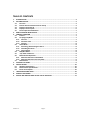
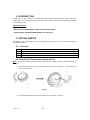
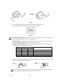
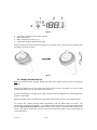
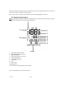
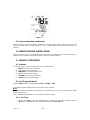
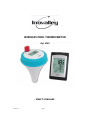
WIRELESS POOL THERMOMETER Ref. SP03 ‐ User’s manual ‐ Version 1.4 Page 1 TABLE OF CONTENTS 1. INTRODUCTION ......................................................................................................................... 3 2. GETTING STARTED...................................................................................................................... 3 2.1 Parts List ............................................................................................................................ 3 2.2 Remote Pool Thermometer Sensor Set Up ........................................................................ 3 2.3 Display Console Set Up ...................................................................................................... 5 2.4 Display Console Layout ...................................................................................................... 6 2.5 Sensor Operation Verification............................................................................................ 7 3. REMOTE SENSOR INSTALLATION ................................................................................................ 7 4. CONSOLE OPERATION ................................................................................................................ 7 4.1 Buttons .............................................................................................................................. 7 4.2 Set (Program) Mode .......................................................................................................... 7 4.2.1 Set Time ........................................................................................................................ 7 4.2.2 Set Alarm Time .............................................................................................................. 8 4.2.3 Set Date ......................................................................................................................... 8 4.3 Alarm Mode ...................................................................................................................... 8 4.3.1 Activating / Deactivating the Alarm ............................................................................... 8 4.3.2 Cancelling the Alarm ..................................................................................................... 8 4.3.3 Snooze Alarm ................................................................................................................ 8 4.4 Min/Max Mode ................................................................................................................. 8 4.5 °C/°F Units of Measure ....................................................................................................... 9 4.6 Multi‐Channel Operation ................................................................................................... 9 4.6.1 Multi‐channel Sensor Initialization ................................................................................ 9 4.6.2 Multi‐channel Sensor Accuracy Note ............................................................................. 9 4.7 Maintenance ..................................................................................................................... 9 5. GLOSSARY OF TERMS ................................................................................................................. 9 6. SPECIFICATIONS ....................................................................................................................... 10 6.1 Wireless Specifications .................................................................................................... 10 6.2 Measurement Specifications ........................................................................................... 10 6.3 Power Consumption ........................................................................................................ 10 7. TROUBLESHOOTING GUIDE ...................................................................................................... 10 8. LIABILITY DISCLAIMER ............................................................................................................. 11 9. DETAILS AND PRECAUTIONS ON THE USE OF BATTERIES .......................................................... 11 Version 1.4 Page 2 1. INTRODUCTION Thank you for your purchase of the Wireless Pool Thermometer with time, date, and indoor temperature. The following user guide provides step by step instructions for installation, operation and troubleshooting. IMPORTANT NOTES: ‐ ONLY INSTALL IN FRESH WATER. DO NOT INSTALL IN SALT WATER. ‐ DO NOT EXCEED THE OPERATIONAL RANGE (‐40 °F TO 140 °F) 2. GETTING STARTED The Wireless Poo Thermometer consists of a display station (receiver), and a wireless thermometer (remote transmitter). 2.1 Parts List QTY 1 Item Display station / Dimensions : 119x74x21mm 1 1 Pool Thermometer transmitter / Dimensions: ø80mmx160mm User Manual 2.2 Remote Pool Thermometer Sensor Set Up Note: To avoid permanent damage, please take note of the battery polarity before inserting the batteries. 1. Twist off the transmitter cover (counterclockwise), as shown in Figure 1. Be careful not to stress the sensor wire. 2. Figure 1 Insert two AA batteries and close the battery door, as shown in Figure 2. Version 1.4 Page 3 Figure 2 3. Locate the dip switches on the inside cover of the lid of the transmitter. Figure 3 displays all three switches in the OFF position (down). Figure 3 Note: The default setting is as follow: Dip Switches 1 and 2 are down, this transmitter is as Channel 1; Dip Switch 3 is up, the temperature unit of this transmitter is °C. 4. Channel Number: The display console supports up to 3 transmitters. To set each channel number, change Dip Switches 1 and 2, as referenced in Table 1. 5. Temperature Units of Measure: To choose the transmitter display units of measure (°F / °C), change Dip Switch 3, as referenced in Table 1. DIP SWITCH FUNCTION 1 2 3 DOWN DOWN ‐‐‐ Channel 1 (factory default setting) UP DOWN ‐‐‐ Channel 2 DOWN UP ‐‐‐ Channel 3 ‐‐‐ ‐‐‐ DOWN °F ‐‐‐ ‐‐‐ UP °C (factory default setting) Table 1 6. Verify the correct channel number (CH) and temperature units of measure (°F /°C) are other display, as shown in Figure 4 and Figure 5. Figure 4 Figure 5 Note: The following illustration shows the full segments of the transmitter LCD for description purposes only and will not appear like this during normal operation. Version 1.4 Page 4 Figure 6 1. Transmitter channel number, total 3 channels 2. Water temperature 3. Water temperature units (°F/ °C) 4. Transmitter indication (flashes when sent) Verify the gasket is properly seated in the guide on transmitter cover. Twist on the transmitter cover (clockwise), as shown in Figure . Figure 7 2.3 Display Console Set Up Note: To avoid permanent damage, please take note of the battery polarity before inserting the batteries. Remove the battery door on the back of the display. Insert 2 AAA 1.5V (alkaline or lithium, avoid rechargeable) batteries in the back of the display console. All of the LCD segments will light up for a few seconds to verify all segments are operating properly, and the unit will beep. Replace the battery door, and fold out the desk stand and place the console in the upright position. The console will instantly display indoor temperature, and the default date and time. The thermometer transmitter will display ‐‐, then update remote temperature on the display within a few minutes. Do not touch any buttons until the remote sensor reports in, otherwise the remote sensor search mode will be terminated, and you must power down and power up the console again by removing batteries. Version 1.4 Page 5 When the remote sensor data has been received, the console will automatically switch to the normal mode, and all further settings can be performed. If the remote does not update, please reference the troubleshooting guide in Section 7. 2.4 Display Console Layout Note: The following illustration shows the full segments of the receiver LCD for description purposes only and will not appear like this during normal operation. Figure8 1. Transmitter channel number 2. Water temperature units (°F/°C) 3. Water temperature 4. Indoor temperature units (°F /°C) 5. Indoor temperature 6. Time and snooze alarm 7. Time of day 8. Date 9. Day of week 10. Min/max icon 11. Transmitter reception (flashes when received) The normal display mode, as shown in Figure 9. Version 1.4 Page 6 Figure 9 2.5 Sensor Operation Verification Verify the indoor and remote (water) temperature matches closely while in the same location. The sensors should be within 4°F (the accuracy is ± 2°F). Allow about 30 minutes for both sensors to stabilize. 3. REMOTE SENSOR INSTALLATION Place the remote sensor into the water (pool, spa, etc). The temperature will take a few hours to stabilize. There is bracket on the thermometer to optionally tether the float. 4. CONSOLE OPERATION 4.1 Buttons The display console includes the following buttons (and location) 1. MODE: on the back of the display 2. C/F: on the back of the display 3. MAX/MIN: on the back of the display 4. SET: on the back of the display 5. CHANNEL: on the top of the display 6. CLEAR: on the top of the display 4.2 Set (Program) Mode Press the MODE button to switch between TIME ‐> ALARM ‐> DATE The following section defines how to set the time, alarm and date. Notes: ‐ After 60 seconds of inactivity, the display will automatically revert to the normal display mode (automatic time out). ‐ Press and hold the C/F button for two seconds to advance rapidly. 4.2.1 Set Time 1. While in the TIME mode, press the SET button, and the hour will begin flashing. Press the C/F button to advance the hour. Make special note of the AM / PM icon. Version 1.4 Page 7 2. Press the SET button again, and the minute will begin flashing. Press the C/F button to advance the minute. 3. Press the SET button again, and the second will begin flashing. Press the C/F button to toggle between 12 hour and 24 hour display mode. 4. Press the SET button again to return to normal mode. 4.2.2 Set Alarm Time 1. While in the ALARM mode, press the SET button, and the alarm hour will begin flashing. Press the C/F button to advance the alarm hour. Make special note of the AM / PM icon. 2. Press the SET button again, and the alarm minute will begin flashing. Press the C/F button to advance the alarm minute. 3. Press the SET button again to return to normal mode. 4.2.3 Set Date 1. While in the DATE mode, press the SET button, and the year will begin flashing. Press the C/F button to advance the year. 2. Press the SET button again, and the month will begin flashing. Press the C/F button to advance the month. 3. Press the SET button again, and the day will begin flashing. Press the C/F button to advance the day. 4. Press the SET button again to return to normal mode. 4.3 Alarm Mode 4.3.1 Activating / Deactivating the Alarm 1. While in the ALARM mode, press the C/F button to activate the alarm. The alarm icon will appear . 2. Press the C/F button again to deactivate the alarm. The alarm icon will disappear. 4.3.2 Cancelling the Alarm When an alarm has been triggered, the alarm will sound and the alarm icon seconds. Press any button on the back of the display to silence the alarm. will flash for 60 4.3.3 Snooze Alarm When an alarm has been triggered, the alarm will sound and the alarm icon will flash for 60 seconds. Press the CHANNEL button on the top of the display or allow the alarm to time out to enter the snooze mode. The snooze icon will flash (ZZ). After five minutes, the alarm will sound again. After five consecutive snooze alarms, the snooze alarm mode will be deactivated. 4.4 Min/Max Mode Notes: ‐ If you have multiple remote temperature sensors, select the Channel you wish to view the min/max data before you enter the min/max mode. ‐ Resetting the minimum and maximum values resets all three channels at the same time for multi‐channel operation. 1. Minimum Values. While in Normal Mode, press the MIN/MAX button to enter the Version 1.4 Page 8 min/max mode. The minimum water temperature and indoor temperature will be displayed. Press the CLEAR button (on the top of the display) to clear the minimum values to the current measured values. 2. Maximum Values. Press the MIN/MAX button again, and the maximum water temperature and indoor temperature will be displayed. Press the CLEAR button (on the top of the display) to clear the maximum values to the current measured values. 3. Press the MIN/MAX button again to exit the min/max mode. 4.5 °C/°F Units of Measure To toggle between °C/°F temperature units of measure on the display, press the C/F button on the back of the display. 4.6 Multi‐Channel Operation The station supports up to 3 remote thermometers (one is included). The optional sensors can be purchased at Inovalley. 4.6.1 Multi‐channel Sensor Initialization Place the multiple remote sensors about 10 feet from the console. Power up the sensors and console in the following order: 1. Power up the first remote thermometer and set the channel number dip switches, as described in Section 2.3. Verify the display reads Channel 1. 2. Power up the second remote thermometer and set the channel number dip switches, as described in Section 2.3. Verify the display reads Channel 2. 3. Power up the third remote thermometer (if available) and set the channel number dip switches, as described in Section 2.3. Verify the display reads Channel 3. 4. Power up the console last and wait about 3 minutes. Press the CHANNEL button on the top of the display to verify all three sensors are communicating to the console. 5. Once verified, you are ready to install the remote thermometers. 4.6.2 Multi‐channel Sensor Accuracy Note Verify the temperature values match closely with the console and sensor array in the same location. The sensors should be within 4°F (the accuracy is ± 2°F). Allow about 30 minutes for all sensors to stabilize. 4.7 Maintenance We recommend inspecting the gasket inside the lid of the floating thermometer with each battery change. Moisten with pool gasket lubricant available from most pool stores. Inspect for any moisture inside the floating thermometer. Replace the gasket every 1 year . To replace the gasket, slide the gasket over the float potion of the floating thermometer and insert into the gasket guide on the lid. 5. GLOSSARY OF TERMS Term Accuracy Version 1.4 Definition Accuracy is defined as the ability of a measurement to match the actual Page 9 value of the quantity being measured. Range is defined as the amount or extent a value can be measured. Range 6. SPECIFICATIONS 6.1 Wireless Specifications Wireless Transition Range without obstacle (in the open air): 300 feet (91,44 meters) under ideal conditions; 100 feet (30 meters) in the majority of the conditions. Frequency: 433 MHz Update Rate: 10 seconds on the remote, 90 seconds on the display console. 6.2 Measurement Specifications The following table provides specifications for the measured parameters. Measurement Range Accuracy Indoor Temperature ‐40 to 140 °F ± 2 °F Water Temperature ‐58 to 140 °F ± 2 °F Resolution 0.1 °F 0.1 °F 6.3 Power Consumption Station : 2 x AAA 1.5V Alkaline batteries Pool thermometer (Remote sensor) : 2 x AA 1.5V Alkaline batteries Battery life: Minimum 12 months for base station Minimum 12 months for remote thermometer sensor (use lithium batteries in cold water climates) 7. TROUBLESHOOTING GUIDE Problem Wireless remote not reporting in to station. Display station contrast is weak Version 1.4 Solution ‐ The maximum line of sight communication range is 100m. Move the display console closer to the remote sensor. ‐ Cycle power on the station by removing and re‐inserting the batteries. The station may have exited the search mode. ‐ Install a fresh set of batteries in the remote thermo‐hygrometer. For cold weather environments, install lithium batteries. ‐ Make sure the remote sensors are not transmitting through solid metal (acts as an RF shield), or earth barrier (down a hill). ‐ Move the station away from electrical noise emitting devices, such as computers, TVs and other wireless transmitters or receivers. ‐ Radio Frequency (RF) Sensors cannot transmit through metal barriers (example, aluminum siding) or multiple, thick walls. Replace station batteries with a fresh set of batteries. Page 10 Temperature on remote sensor and station disagree ‐ The remote sensor updates every 10 seconds. ‐ The display reads the sensor every 90 seconds. ‐ If transmission is intermittently lost, the sensor and station temperature values will disagree. 8. LIABILITY DISCLAIMER Please help in the preservation of the environment and return used batteries to an authorized depot. The electrical and electronic wastes contain hazardous substances. Disposal of electronic waste in wild country and/or in unauthorized grounds strongly damages the environment. Reading the “User manual” is highly recommended. The manufacturer and supplier cannot accept any responsibility for any incorrect readings and any consequences that occur should an inaccurate reading take place. This product is designed for use in the home only as indication of weather conditions. This product is not to be used for medical purposes or for public information. This product is not a toy. Keep out of the reach of children. 9. DETAILS AND PRECAUTIONS ON THE USE OF BATTERIES ‐ Discard a used battery in nature or garbage pollutes and prevents the recovery of recyclable materials. It is therefore important to limit consumption of batteries and follow these guidelines: focus on alkaline batteries (that last longer than the saline batteries) and when possible, rechargeable batteries deposit batteries and accumulators in specific containers arranged among traders. For example, metals will be valued and polluted the environment because they contain heavy metals hazardous to health and the environment primarily (cadmium and nickel) ‐ The piles must installation by respecting the polarity indicated on the apparatus and the pile. An incorrect positioning can is to damage the apparatus, is to cause escapes on the level of the pile, is to the extreme to cause a fire or the explosion of the pile. ‐ To ensure proper operation, the batteries must be in good condition. In case of abnormality in the functioning of the device, put fresh batteries ‐ Never attempt to recharge non‐rechargeable batteries. They could run, warm up, causing a fire or explosion. ‐ Replace all batteries at the same time. Never mix zinc batteries with alkaline batteries or rechargeable batteries ‐ The batteries must be removed from the device ‐ Also, remove the batteries from your device if you do not use it for a long time, if the batteries may leak and cause damage. ‐ Never try to short‐circuit the battery terminals ‐ Never dispose of batteries in fire, they might explode ‐ Charging of batteries is to be performed by an adult. ‐ Remove batteries from the device before reloading. ‐ We recommend an adult to supervise children when they change the batteries so that these Version 1.4 Page 11 instructions are complied with or to make himself the replacement of batteries. ‐ If a battery is swallowed, immediately consult a doctor or poison control center nearest you. Do not forget to carry the product with you. Version 1.4 Page 12