1
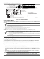
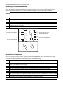
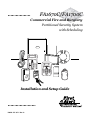
FA1670C/FA1700C
Commercial Fire and Burglary
Partitioned Security System
with Scheduling
ARMED
READY
R
BS/ESC
1
2
A
B
4
7
C
E
S
F
T
0
SPACE
ARMED
9
8
SHIFT
3
6
5
D
N/Y
READY
X
#
ENTER
FA 5 6 0
R
A
1 OFF
2 AWAY
3STAY
B
4 MAX
5TEST
6BYPASS
C
7INSTANT
8 CODE
9 CHIME
D
READY
0
#
FA260
Installation and Setup Guide
R
K0376-1V5 4/11 Rev. A
Table of Contents
• • • • • • • • • • • • • • • • • • • • • • • • • • • • • • • • • • • • • • • • • • • • • • • • •
Commercial Fire and Burglary ............................................................................................................. i
General Requirements ...................................................................................................................................... ix
Programming Field Settings for UL864 Compliance...................................................................................... ix
SECTION 1....................................................................................................................................... 1-1
SIA Installations .............................................................................................................................................1-1
About the FA1670C/FA1700C ........................................................................................................................1-1
Features ...........................................................................................................................................................1-1
Guidelines for Wiring a System .....................................................................................................................1-4
SECTION 2....................................................................................................................................... 2-1
Theory of Partitioning.....................................................................................................................................2-1
Setting-Up a Partitioned System ...................................................................................................................2-1
Common Lobby Logic ......................................................................................................................................2-1
Master Keypad Setup and Operation ............................................................................................................2-3
SECTION 3....................................................................................................................................... 3-1
Mounting the Control Cabinet .......................................................................................................................3-1
Installing the Cabinet Lock ............................................................................................................................3-1
Mercantile Premises Listing Guidelines........................................................................................................3-1
Mercantile Safe and Vault Listing Guidelines ..............................................................................................3-2
Commercial Fire Guidelines ...........................................................................................................................3-2
Installing the Control's Circuit Board ...........................................................................................................3-3
Installing the Keypads ....................................................................................................................................3-3
Installing External Sounders .........................................................................................................................3-5
Auxiliary Relay Connections ..........................................................................................................................3-8
Telephone Line Connections...........................................................................................................................3-9
Main Dialer Connections ................................................................................................................................3-9
Wiring Burglary and Panic Devices to Zones 1-8........................................................................................3-10
Installing V-Plex Devices..............................................................................................................................3-14
Wireless Zone Expansion ..............................................................................................................................3-17
Installing Output Devices.............................................................................................................................3-21
Installing a Remote Keyswitch.....................................................................................................................3-22
Installing a Remote Keypad Sounder (For Commercial Burglary use only) .............................................3-23
Communicators Connected to the ECP........................................................................................................3-24
Access Control Using VistaKey ....................................................................................................................3-25
Event Log Connections .................................................................................................................................3-27
Installing the 4286 VIP Module ...................................................................................................................3-28
Connecting a Battery Sense Module ..............................................................................................................3-30
Connecting the Transformer ........................................................................................................................3-30
Earth Ground Connections ...........................................................................................................................3-31
Determining the Control’s Power Supply Load...........................................................................................3-31
Determining the Size of the Standby Battery .............................................................................................3-34
SECTION 4....................................................................................................................................... 4-1
Program Modes................................................................................................................................................4-1
Entering and Exiting Programming Mode ....................................................................................................4-1
iii
Table of Contents
Data Field Programming Mode ......................................................................................................................4-1
#93 Menu Mode Programming .......................................................................................................................4-2
Zone Number Designations ............................................................................................................................4-4
Zone Response Type Definitions.....................................................................................................................4-6
Zone Input Type Definitions...........................................................................................................................4-8
Programming for Access Control....................................................................................................................4-9
Programming for Communicator .................................................................................................................4-11
SECTION 5....................................................................................................................................... 5-1
About Data Field Programming .....................................................................................................................5-1
Programming Data Fields ..............................................................................................................................5-1
SECTION 6....................................................................................................................................... 6-1
Time Window Definitions ...............................................................................................................................6-2
Open/Close Schedules Definitions..................................................................................................................6-3
Scheduling Menu Mode...................................................................................................................................6-4
Time Windows .................................................................................................................................................6-5
Daily Open/Close Schedules ...........................................................................................................................6-6
Holiday Schedules ...........................................................................................................................................6-6
Time-Driven Events ........................................................................................................................................6-7
Limitation of Access Schedules ....................................................................................................................6-11
Temporary Schedules....................................................................................................................................6-12
User Scheduling Menu Mode........................................................................................................................6-14
SECTION 7....................................................................................................................................... 7-1
General Information........................................................................................................................................7-1
Unattended Download (For Burglary Use Only) ..........................................................................................7-1
Getting On-Line with a Control Panel...........................................................................................................7-3
Scheduled Download (For Burglary Use Only) .............................................................................................7-4
Direct-Wire Downloading ...............................................................................................................................7-4
Telco Handoff...................................................................................................................................................7-4
SECTION 8....................................................................................................................................... 8-1
General Information........................................................................................................................................8-1
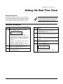
Setting the Time and Date .............................................................................................................................8-1
SECTION 9....................................................................................................................................... 9-1
General Information........................................................................................................................................9-1
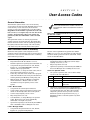
User Codes and Levels of Authority...............................................................................................................9-1
Multiple Partition Access................................................................................................................................9-2
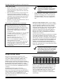
Adding a Master, Manager, or Operator Code ..............................................................................................9-3
Changing a Master, Manager, or Operator Code..........................................................................................9-4
Deleting a Master, Manager, or Operator Code ............................................................................................9-4
Exiting the User Edit Mode............................................................................................................................9-4
SECTION 10................................................................................................................................... 10-1
Battery Test ...................................................................................................................................................10-1
Dialer Test .....................................................................................................................................................10-1
Fire Drill Test (Code + [#] + 69) ...................................................................................................................10-1
One-Man Fire Walk-Test (Code + [#] + 68) .................................................................................................10-1
Burglary Walk-Test.......................................................................................................................................10-2
Armed Burglary System Test .......................................................................................................................10-2
Testing Wireless Transmitters .....................................................................................................................10-2
iv
Table of Contents
Trouble Conditions ........................................................................................................................................10-2
To the Installer ..............................................................................................................................................10-2
APPENDIX A .................................................................................................................................. A-1
UL Installation Requirements....................................................................................................................... A-1
UL864/NFPA Local Fire ................................................................................................................................ A-1
UL864/NFPA Central Station and Remote Station Fire ............................................................................. A-1
Commercial Burglary Requirements ............................................................................................................ A-1
UL609 Local Mercantile Premises/Local Mercantile Safe & Vault ............................................................ A-2
UL365 Police Station Connected Burglar Alarm ......................................................................................... A-2
UL1610 Central Station Burglary Alarm ..................................................................................................... A-2
APPENDIX B .................................................................................................................................. B-1
APPENDIX C .................................................................................................................................. C-1
APPENDIX D.................................................................................................................................. D-1
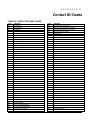
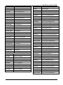
TABLE OF CONTACT ID EVENT CODES ................................................................................................. D-1
Event Log Alpha Descriptors......................................................................................................................... D-2
v
List of Figures
• • • • • • • • • • • • • • • • • • • • • • • • • • • • • • • • • • • • • • • • • • • • • • • • •
Figure 1-1: Isolating Fire Devices from Burglary Devices
1-5
Figure 3-1: Installing the Lock
3-1
Figure 3-2: Cabinet Attack Resistance Considerations
3-2
Figure 3-3: Commercial Fire Installation Considerations
3-2
Figure 3-4: Mounting the PC Board
3-3
Figure 3-5: Keypad Connections to Control Panel
3-4
Figure 3-6. ECP Isolator Wiring
3-4
Figure 3-7. Using a Supplementary Power Supply
3-4
Figure 3-8: Wiring Auxiliary Relay for Alarm Activation
3-8
Figure 3-9: Wiring Auxiliary Relay for Smoke Detector Reset
3-9
Figure 3-10: 2-Wire Smoke Detector on Zone 1 (for zone 2 use terminals 17 and 18)
3-11
Figure 3-11: 4-Wire Smoke Detectors
3-12
Figure 3-12. Wiring Latching Glassbreaks to Zone 8
3-13
Figure 3-13: Wiring a Normally Closed Sensor Loop for Tamper Supervision
3-14
Figure 3-14: Wiring a Normally Open Sensor Loop for Tamper Supervision
3-14
Figure 3-15: Polling Loop Connections to the Control Panel
3-16
Figure 3-16: Polling Loop Connections Using One 4297 Extender Module
3-16
Figure 3-17: Polling Loop Connections Using Multiple Extender Modules
3-17
Figure 3-18: Installing the 5881ENHC with Tamper Protection
3-19
Figure 3-19: 5881ENHC RF Receiver (cover removed)
3-19
Figure 3-20: 4204 Relay Module
3-21
Figure 3-21: 4204CF Relay Module
3-22
Figure 3-22: Remote Keyswitch Wiring
3-23
Figure 3-23: Remote Keypad Sounder Wiring
3-23
Figure 3-24: Wiring Communicator to Keypad Terminals
3-25
Figure 3-25: Wiring the VistaKey
3-27
Figure 3-26: Printer Connections to the 4100SM
3-28
Figure 3-27: 4286 VIP Module Connections
3-29
Figure 3-28: Wiring the Battery Sense Module
3-30
Figure 3-29: Connecting the Backup Batteries
3-35
Figure 7-1: Direct-Wire Downloading Connections
7-4
FA1670C/ FA1700C Summary of Connections Diagram...................................................................................Inside Back Cover
vi
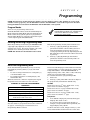
Conventions Used in This Manual
• • • • • • • • • • • • • • • • • • • • • • • • • • • • • • • • • • • • • • • • • • • • • • • • •
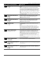
Before you begin using this manual, it is important that you understand the meaning of the following symbols (icons).
UL
These notes include specific information that must be followed if you are installing this system for
a UL Listed application.
These notes include information that you should be aware of before continuing with the
installation, and that, if not observed, could result in operational difficulties.
!
This symbol indicates a critical note that could seriously affect the operation of the system, or
could cause damage to the system. Please read each warning carefully. This symbol also
denotes warnings about physical harm to the user.
ZONE PROG?
1 = YES 0 = NO 0
✴00
Many system options are programmed in an interactive mode by responding to
alpha keypad display prompts. These prompts are shown in a single-line box.
Additional system options are programmed via data fields, which are indicated by a “star”
(✴) followed by the data field number.
PRODUCT MODEL NUMBERS:
Unless noted otherwise, references to specific model numbers represent Honeywell products.
vii
viii
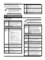
UL864 (Commercial Fire) Compliance
• • • • • • • • • • • • • • • • • • • • • • • • • • • • • • • • • • • • • • • • • • • • • • • • •
General Requirements
The FA1670C/FA1700C control panels provide features that allow the system to meet UL864 Commercial Fire
requirements. To meet these requirements, follow the guidelines outlined in this section.
•
•
•
•
•
•
•
•
•
The reporting of bypassed points to the central station must be enabled in Report Code Programming mode.
Fire alarm notification circuits must be supervised (e.g., supervisory zones 970 and 971 for Bell 1 and Bell 2 outputs)
Only one relay of the 4204CF can be programmed for a NAC. If the 4204CF relay is programmed as a NAC, the stop
action must be programmed as a zone type 62, Bell 2 Timeout.
Output devices are not intended for overriding automatic fire and building functions.
Line cut detection must be enabled for both the main and backup phone lines (supervisory zones 974 and 975).
Access Control Devices cannot be used.
Audio Alarm Verification Devices cannot be used.
Remote downloading can only be performed if a service person is at the premises.
All supervision zones for the polling loop, RF receivers, keypads, NAC outputs, and telephone lines that are used, must
be enabled as zone type 19 (24-hour trouble).
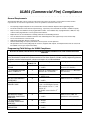
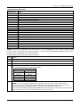
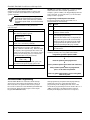
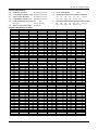
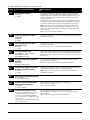
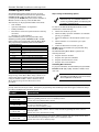
Programming Field Settings for UL864 Compliance
NOTICE TO USERS, INSTALLERS, AUTHORITIES HAVING JURISDICTION, AND OTHER INVOLVED
PARTIES
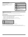
This product incorporates field-programmable software. In order for the product to comply with the requirements
in the Standard for Control Units and Accessories for Fire Alarm Systems, UL 864, certain programming features
or options must be limited to specific values or not used at all as indicated below.
Program feature or option
Permitted in
UL864? Y/N
Possible settings
Settings permitted in UL 864
✱08 TEMPORAL SIREN
PULSE
N
0 = disable
1 = enable
Not used at this time. Must
be set to “0” (disable).
✱13 ALARM SOUNDER
(BELL) TIMEOUT
Y
Must be set to “3” (Minimum
of 6 minutes).
✱14 TRIGGER OR RS232
N
✱17 AC LOSS KEYPAD
SOUNDING
✱20 VIP MODULE
PHONE CODE
N
Enter 01-15 multiplied by 2
minutes. 00 = no timeout.
0 = trigger
1 = RS232 input
0 = disable
1 = enable
1-9 = first digit of access code
∗ or # = second digit of access
code (enter # +11 for “∗”, or #
+12 for “#”).
st
To disable enter 0 for the 1
digit.
0 = disable
1 = enable
✱22 KEYPAD PANIC
ENABLES (PARTITION
SPECIFIC)
✱23 MULTIPLE
ALARMS (PARTITION
SPECIFIC)
✱26 INTELLIGENT TEST
REPORTING
N
N
Must be set to “0”.
Must be set to “1” (enabled).
Not used. Must be set to “00”.
Must be set to “000” for
partition 1 in fire systems.
N
0 = disable
1 = enable
Must be set to “1” (enabled).
N
0 = disable
1 = enable
Must be set to “0” (disable).
ix
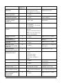
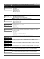
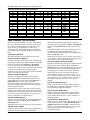
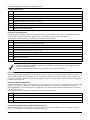
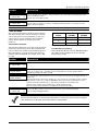
Program feature or option
✱27 TEST REPORT
INTERVAL
✱28 POWERUP IN
PREVIOUS STATE
✱37 DOWNLOAD
COMMAND ENABLES
✱41 NORMALLY
CLOSED OR EOLR
(ZONES 3-8)
✱42 DIAL TONE PAUSE
Permitted in
UL864? Y/N
Y
Y
N
N
Y
✱44 RING DETECTION
COUNT
N
✱54 UNATTENDED
MODE
✱56 DYNAMIC
SIGNALING DELAY
✱77 AUTO TROUBLE
RESTORE
✱80 ZONE TYPE
RESTORES FOR TYPES
9, 10 & 14
1✱12 PROGRAM
NOTIFICATION SIGNAL
1✱13 SYSTEM SENSOR
REVERSING RELAY
N
1✱18 AFFECTS LOBBY
N
1✱19 ARMS LOBBY
N
1✱22 thru 1✱25 CROSSZONING PAIRS (1 – 4)
1✱28 RF TRANSMITTER
LOW BATTERY SOUND
N
1✱29 RF TRANSMITTER
LOW BATTERY
REPORTING
N
x
Y
Y
N
Possible settings
Settings permitted in UL 864
Enter 0001-9999 for the test
report interval in hours.
Enter 0000 for test reporting.
0 = disable
1 = enable
0 = disable
1 = enable
0 = EOLR supervision
1 = N.C. loops
Must be set to “0024”
(Maximum 24 hours)
Enter the wait time for dial
tone detection:
0 = 5 seconds; 1 = 11 seconds;
2 = 30 seconds.
Enter 00 to disable ring
detection.
Enter 01-14 for ring counts of
1-14.
Enter 15 to select Answering
Machine Defeat Mode
0 = disable
1 = enable
Enter 00-15 times 15 seconds.
Must be set to “0” (5 seconds).
0 = disable
1 = enable
0 = disable
1 = enable
Must be set to “1” (enable).
Must be set to “0” for all
entries (disable).
Must be set to “0” (EOLR
Supervision).
Must be set to “00” (disable).
Must be set to “0” (disable).
Must be set to “6” (90
seconds).
Must be set to “1” (enable).
Must be set to “1” (enable) for
zone type 9.
Y
0 = no
1 = yes
Must be set to “1” (yes).
N
0=use neither Zone 1 or Zone
2 inputs
1=use Zone 1 input;
2=use Zone 2 input;
3=use Zone 1 and Zone 2
inputs.
0 = disable
1 = enable
0 = disable
1 = enable
Enter 001-250
Enter 000,000 to disable
Not Used. Must be set to “0”.
0 = disarmed state only
1 = both armed and disarmed
states
0 = disable
1 = enable
Must be set to “1” (both
armed and disarmed states).
N
Must be set to “0” (disabled)
for partition 1.
Must be set to “0” (disabled)
for partition 1.
Must be set to “000,000”
(disabled) for fire zones.
Must be set to “1” (enable).
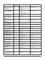
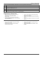
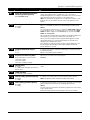
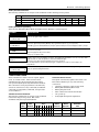
Program feature or option
1✱30 RF RECEIVER
SUPERVISION CHECKIN INTERVAL
Permitted in
UL864? Y/N
N
1✱31 RF TRANSMITTER
CHECK-IN INTERVAL
N
1✱35 ACCESS CONTROL
DIALER ENABLES
N
1✱44 WIRELESS
KEYPAD TAMPER
DETECT
1✱45 EXIT DELAY
SOUNDING (PARTITION
SPECIFIC)
1✱48 WIRELESS
KEYPAD ASSIGNMENT
N
1✱49 SUPPRESS TX
SUPERVISION SOUND
1✱53 DISABLE
DOWNLOAD CALLBACK
1✱57 5800 RF BUTTON
GLOBAL ARM
1✱58 5800 RF BUTTON
FORCE ARM
1✱60 ZONE 5 AUDIO
ALARM VERIFICATION
1✱69 PRINTER TYPE
Possible settings
Settings permitted in UL 864
Enter 02–15 times 2 hours (4–
30 hours)
Enter 00 to disable receiver
supervision
Enter 02–15 times 2 hours (4–
30 hours)
Enter 00 to disable
transmitter supervision
0 = disable
1 = enable
0 = disable
1 = enable
Maximum is 02 (4 hours) for
fire installations.
Maximum is 02 (4 hours) for
fire installations.
Not used. Must be set to “0”.
Not used. Must be set to “0”.
N
0 = disable
1 = enable
Must be set to “0” (disable)
for partition 1.
N
0 = none
1-8 = partition number
0 = disable
1 = enable
Not used. Must be set to “0”.
N
0 = callback required
1 = no callback required
Must be set to “0” (callback
required).
N
0 = disable
1 = enable
Must be set to “0” (disable).
N
0 = disable
1 = enable
Must be set to “0” (disable).
N
0 = disable
1 = enable
Must be set to “0” (disable).
N
0 = parallel printer
1 = serial printer
0 = disable
1 = enable
0 = 1200
1 = 300
01-96 = relay number
00 = relay not used.
Not used.
N
Must be set to “0” (disable).
1✱72 EVENT LOG
PRINTER ONLINE
N
Not used. Must be set to “0”.
1✱73 PRINTER BAUD
RATE
N
1✱76 CONTROL RELAY
(PART-SPECIFIC)
N
1✱78 EXTENDED HOME
CONT EVENTS
1✱79 HOME CONTROL
EVENTS
N
1 = extended
0 = limited
Not used. Must be set to “0”.
N
Not used. Must be set to “0”
in each entry.
2✱07 AUTO-DISARM
DELAY (PART
SPECIFIC)
N
2✱18 ENABLE GOTO
FOR THIS PARTITION
(partition-specific)
N
0 = disable
1 = enable
00 = no delay.
01-14 times 4 minutes (04-56)
delay.
15 = no auto disarming.
0 = disable
1 = enable
Not used.
Must be set to “00” (relay not
used) for partition 1.
Must be set to “15” (no auto
disarming) for partition 1.
Must be set to “0” (disable)
for partition 1.
xi
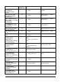
Program feature or option
2✱21 SUPERVISION
PULSES FOR
Permitted in
UL864? Y/N
N
Possible settings
Settings permitted in UL 864
0 = disable
1 = enable
Must be set to “00000”
(disable).
N
0 = disable
1 = enable
Must be set to “0” (disable)
for partition 1.
N
0 = disable
1 = enable
Must be set to “0” (disable)
for partition 1.
N
0 = disable
1 = enable
Must be set to “0” (disable)
for partition 1.
N
NA
Not used. Must be set to “0”.
N
0 = disable
1 = enable
Must be set to “1” (enable).
N
0 = disable
1 = enable
Must be set to “0” (disable).
N
0 = Trouble on open/Supv on
short
1 = Supv on open/Supv on
short
Must be set to “0”.
N
0 = Silenced by User Code +
OFF
1 = Silenced when zone
restores
Enter 01-15 times 2 seconds
Enter 00 for no delay
Must be set to “0” (Silenced
by User Code + OFF).
COMMUNICATIONS
DEVICE
2✱22 DISPLAY FIRE
ALARMS OF OTHER
PARTITIONS
2✱23 DISPLAY BURG,
PANIC AND CO ALARMS
FOR OTHER
PARTITIONS
2✱24 DISPLAY
TROUBLES OF OTHER
PARTITIONS
2✱30 THROUGH 2✱88
(PAGER OPTIONS)
3✱01 EVENTS DISPLAY
LOCK
3✱12 ZN TYPE 18 DELAY
USE
3✱13 FIRE
SUPERVISORY
RESPONSE TO
OPEN/SHORT (APPLIES
TO ZONE TYPE 18)
3✱14 WATERFLOW
ALARM SILENCE
OPTION
3✱16 DELAY FOR ZONE
TYPES 17 & 18
(Waterflow/Supervisory)
3✱18 EXTENDED
DELAY FOR ZONE
TYPES 17 & 18 Multiplies
delay in 3*16 x 4)
3✱19 AUXILIARY INPUT
ALTERNATE FUNCTION
ENABLE
3✱20 TRIGGER
OUTPUTS FUNCTION
SELECTION
3✱21 MAXIMUM
NUMBER OF DIALER
ATEMPTS
3✱50 ZONE TYPE
RESTORE ENABLES
FOR TYPES 16-18
xii
N
Must be set to 00 (no delay).
N
0 = no extended delay
1 = multiply delay by 4
Must be set to 0 (no extended
delay).
N
0 = disable
1 = enable
Must be set to 0 (disable).
N
0 = remote keypad sounder
1 = keyswitch LEDs
Must be set to 0 (remote
keypad sounder).
Y
1-8
Must be set at 3, 4 or 5.
N
0 = disable
1 = enable
Must be set to “1” (enable).
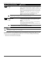
Program feature or option
3✱60 BELL 2 & AUX
RELAY TIMEOUT
3✱82 ENABLE
BURGLARY FEATURES
ON PARTITION 1
RESTRICTION FOR FIRE
RELAYS
Permitted in
UL864? Y/N
Y
N
Y
Possible settings
Settings permitted in UL 864
Enter 01-15 multiplied by 2
minutes.
00 = no timeout.
0 = disable
1 = enable
Must be set to “3” (Minimum
of 6 minutes).
Yes
No
Restriction for # 70 must be
set to Yes when
programming fire relays.
Must be set to “0” (disable).
xiii
xiv
S E C T I O N
1
General Description
• • • • • • • • • • • • • • • • • • • • • • • • • • • • • • • • • • • • • • • • • • • • • • • • •
SIA Installations
The FA1670C and FA1700C are not certified as SIA compliant, but can be programmed for False Alarm Reduction. To
program for False Alarm Reduction, follow the SIA Guidelines noted in the applicable programming fields.
About the FA1670C/FA1700C
The FA1670C/FA1700C is an 8-partition, UL Listed commercial fire and burglary control panel with the following
features:
•
Up to 128 zones for FA1670C; 250 zones for FA1700C (hardwired, polling loop, and wireless zones)
•
Up to 150 user codes for FA1670C; 250 user codes for FA1700C
•
Supervision of Notification Appliance Circuits, phone lines, keypads, RF receivers, and output devices
•
Scheduling capabilities (allows certain operations to be automated)
The FA1670C/FA1700C can interface with the following devices:
•
An ECP Communications Device that can send Contact ID messages
•
An AUI/GUI
•
An access control system by using the Honeywell VistaKey module (via the polling loop)
UL
The access control function is not Listed for use with the FA1670C/FA1700C Control Panel in a UL Commercial Fire
Installation.
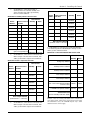
NOTE: All references in this manual for number of zones, number of user codes, number of access cards and
the event log capacity, use the FA1700C’s features. The following table lists the differences between the
FA1670C and the FA1700C control panels. All other features are identical.
Feature
FA1670C
FA1700C
Number of Zones
128
250
Number of User Codes
150
250
Event Log Capacity
512
1000
8
15
250
500
VistaKey Modules
Number of Access Cards
Features
Hardwire and Optional Expansion Zones
•
Provides 8 hardwire zones.
•
Supports up to 16 2-wire smoke detectors each on zone 1 and zone 2 (32 total).
•
Automatically resets 4-wire smoke detectors if the Aux Relay is programmed for smoke reset (3*61 = 2).
•
Triggers the built-in sounders on other hardwired smoke detectors if one smoke detector annunciates an alarm. This
feature requires a System Sensor RRS-MOD.
•
Supports up to 50 2-wire latching glassbreak detectors on zone 8.
•
Supports up to 242 additional expansion zones (120 for the FA1670C) using a built-in polling (V-Plex) loop.
•
Supports up to 250 wireless zones (128 for the FA1670C) fewer if using hardwire and/or polling loop zones.
•
Can program burglary zones as silent in the alarm condition (alarm output is silent and the keypad does not display
or sound the alarm).
•
Provides three keypad panic keys: 1 + ✴ (A), ✴ + # (B), and 3 + # (C).
1-1
FA1670C/FA1700C Installation and Setup Guide
Peripherals Devices
•
Supports up to 31 addressable devices, (keypads, RF receivers, relay modules, etc.).
•
Supervises devices (keypads, RF receivers, and relay modules) and individual relays (up to 32), as well as system
zones (RF receivers and keypad panics).
•
Provides 96 outputs using 4204 and 4204CF Relay Modules, and V-Plex Relay Modules can activate outputs in
response to system events (alarm condition), at a specific time of day, at random times, and manually using the #70
Relay Command Mode.
•
Supports one additional style-Y supervised Notification Appliance Circuit using a 4204CF.
•
Supports the ADEMCO 4146 Keyswitch on any one of the system's eight partitions.
•
Can be used with Commercial Fire Listed 24VDC Power Supplies.
•
Supports the Honeywell 4286 VIP Module, which allows access to the system from either a remote location or on the
premises
Arming/Disarming and Bypassing
•
Can arm the system with zones faulted (Vent Zone). These zones are automatically bypassed and can be
programmed to automatically unbypass when the zone restores.
•
Can arm with entry/exit and interior type zones faulted (Arm w/Fault). These zones must be restored before the exit
delay expires, otherwise an alarm is generated.
UL
•
•
•
•
•
•
•
•
•
Vent zones cannot be used in UL installations.
You must disable the Force Arm option (used in conjunction with the Arm w/Fault option), in UL installations.
Provides global arming capability (ability to arm all partitions the user code has access to in one command).
Can Quick Exit an armed premises without having to disarm and then rearm the system.
Can be armed in one of three STAY modes or Instant modes, automatically bypassing specific burglary zones
regardless of the zone response type.
Can automatically bypass specific zones if no one exits the premises after arming (Auto-STAY). Auto-STAY will not
occur if the system is armed via an RF transmitter, VIP module, scheduling, access control, keyswitch or
downloading.
Can bypass a group of zones with one set of keystrokes.
Supports Exit Error Logic, whereby the system can tell the difference between a regular alarm and an alarm caused
by leaving an entry/exit door open. If the system is not subsequently disarmed, faulted entry/exit zone(s) and/or
interior zones are bypassed and the system arms.
Supports Recent Close report, which is designed to notify the central station that an alarm has occurred within 2
minutes after the exit delay has expired.
Partitioning
•
Can control 8 separate areas (partitions) independently, each functioning as if it had its own separate control. All
fire zones must be assigned to partition 1.
•
Provides a Common Lobby partition, which can be programmed to arm automatically when the last partition is
armed, and to disarm when the first partition is disarmed.
•
Provides a Master partition (9), used for the purpose of viewing the status of all partitions at the same time.
•
Can display fire, burglary, panic, and trouble conditions at all other partitions’ keypads (selectable option).
Scheduling
•
Can automate system functions, such as arming, disarming, and activation of outputs (e.g., lights).
•
Provides access schedules (for limiting system access to users by time).
•
Provides an End User Output Programming Mode, allowing the user to control outputs.
Access Control
•
Supports 15 VistaKey modules single-door access control modules (FA1670C supports 8).
•
Supports up to 500 access cards (250 for the FA1670C).
•
Can store access control events in the event log.
System Communication
•
•
1-2
Provides supervision of the phone lines (main and backup)
Supports the 5140DLM optional backup dialer for the second phone line.
Section 1 - General Description
•
Supports ADEMCO Contact ID; ADEMCO High Speed; ADEMCO Express; and 3+1, 4+1, and 4+2 ADEMCO and
Sescoa/Radionics Low-Speed formats.
The system is shipped defaulted for Contact ID communication. It is the only format capable of uniquely reporting all
250 zones, as well as openings and closings for all 250 users. This requires central stations to be equipped with the
ADEMCO 685 (using software level 4.10 or higher) or MX8000 receiver to fully support all new FA1670C/FA1700C
report codes. If you need to update your 685 or MX8000 receiver, contact your distributor.
•
Provides the Dialer Queue Report in the event of a loss of communications between the dialer and the central
station, i.e. telco loss. The total events that will be queued up are 128 (91 Burg + 37 Life Safety). A Dialer Queue
Overflow report (E354) will be sent if the report queue goes beyond its limits. Note that: Life Safety includes Fire,
CO, 24 HR Silent/Audible/Auxiliary, and Duress. Life Safety events may go beyond 37 (up to 128) if there are no
Burg events in the queue. If all dialer attempts are exhausted before communication to the central station is
restored, the queue will be cleared.
Downloading
•
Supports upload and download capability. (Downloading must be site-initiated for Commercial Fire installations.)
•
Can perform unattended downloading (no one at the downloading computer).
•
Provides an Installer Unattended Program Mode. This allows the installer to program the download phone number,
subscriber number, and primary central station receiver phone number without entering the normal program mode.
•
Can periodically and automatically perform a scheduled download.
•
Revision 4.0 and above panels can be downloaded via the 7845i-ent using Compass revision 1.5.8 or above.
UL
Downloading is not listed for use in UL installations.
Event Log
•
Provides an event log (history log) that can store up to 1000 events (512 for the FA1670C).
•
Can view the event log on an alpha keypad or AUI.
Fire Walk-Test Mode
•
Provides an automatic test of integrated V-Plex devices that have the automatic test feature.
•
Can display all fire zones that remain untested.
•
Can log test results in the event log.
•
Can report the test results to the central station.
Additional Features
•
Provides two style-Y supervised Special Application Notification Appliance Circuits.
•
Provides an auxiliary relay (form C) that can activate alarms troubles/supervisories, reset 4-wire smoke detectors, or
as a battery saver (removes power from non-critical loads 4 hours after AC power loss).
•
Provides up to 60 installer-defined, custom words that can be used for zone descriptors.
•
Provides 32 keypad macro commands (each macro is a series of keypad commands of up to 32 keystrokes) using the
A, B, C, and D keys by partition.
•
Provides cross-zone capability, which helps prevent false alarms by preventing a zone from going into alarm unless
its cross-zone is also faulted within a 5-minute period.
•
Contains a built-in User Manual, which provides the end user with a brief explanation of the function of a key when
the user presses any of the function keys on the keypad for 5 seconds.
•
Provides trigger outputs, which may interface with Communicator equipment or other devices such as keyswitch
LEDs, or printer.
•
Provides an option to have trouble and supervisory conditions to automatically clear from the display when the zone
returns to the ready/normal state (entry of Code + OFF is not required).
•
Provides Maintenance Signal support for certain smoke detectors (5192SD, 5192SDT, 5193SD, 5193SDT).
At least one 2-line alpha keypad (FA570KP/FA570KPCR) must be connected to the system for programming (if you
are using keypad programming), and must remain connected to the system in order to allow the primary user to
program additional user codes into the system at a later time.
1-3
FA1670C/FA1700C Installation and Setup Guide
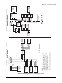
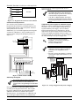
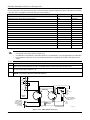
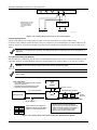
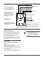
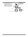
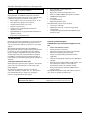
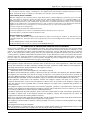
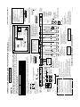
Guidelines for Wiring a System
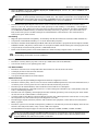
The installer must keep certain guidelines in mind while installing a system. The FA1670C/FA1700C contains an ECP
bus and a polling loop bus for connecting Fire and Burglary devices. When installing a Fire ONLY system or Burglary
ONLY system both busses may be used interchangeably. When installing a Commercial Fire and Burglary System all
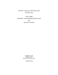
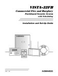
Fire devices must be isolated from the Burglary devices. This is accomplished by using an isolator as shown in Figure 11. Additionally, in Commercial Fire installations, the primary keypad must be connected to Keypad Port 2 mounted
within 20 feet of the control panel, and wired in conduit.
A fault on an SLC may disable all NACs on that circuit therefore only one NAC per SLC circuit may be used.
Synchronization is based on the individual zone output basis only, not between each sync module. There is no
synchronization between the individual sync modules.
Notification Appliance Circuit (NAC) must be wired and isolated or Riser Conductors must be installed in accordance
with the survivability from attack by fire requirements in the National Fire Alarm Code, NFPA 72.
1-4
BLACK -
RED +
BLACK -
RED +
USE CABLE
4142TR
(SUPPLIED)
BLACK -
YELLOW DATA
GREEN DATA
BLACK -
RED +
YELLOW DATA
GREEN DATA
RED +
LOOP DEVICES THAT ARE USING ONLY 2-WIRE CONNECTIONS.
3. POLLING LOOP TERMINAL 29 CAN BE USED FOR POLLING
MUST BE EITHER ALL FIRE OR ALL BURGLARY.
NO COMBINATION OF FIRE/BURGLARY DEVICES IS
PERMITTED.
2. WHEN USING A 4297 FOR ISOLATION, ISOLATED DEVICES
USING A T-TAP FOR MODULE CONNECTION. ACTUAL T-TAP
CONNECTIONS MUST BE CONTAINED WITHIN THE
ENCLOSURE.
FIRE BURGLARY
RED +
BLACK -
GREEN DATA
YELLOW DATA
RED +
BLACK -
GREEN DATA
BLACK -
YELLOW DATA
GREEN DATA
ECP
ISOLATOR
YELLOW DATA
NOTES:
1. FOR CLARITY OF THIS DRAWING THE ECP BUS IS SHOWN
4204CF
RF RECEIVER
RED +
YELLOW DATA
ECP BUS
11 12 13 14
FA1670C / FA1700C PANEL PANEL
COMMUNICATORS
GREEN DATA
7845i-ent
PRIMARY
KEYPAD
FA570CR
YELLOW DATA
KEYPAD PORT 2
GREEN DATA
ISOLATION OF FIRE AND BURGLARY DEVICES
ON THE ECP BUS
4204
BURGLARY
KEYPAD
FA570KP
AUX POWER
CANNOT BE
USED ON
"FIRE LOOP"
4208SN
4208SNF
4208U
5192SDT
5193SDT
4190SN
4193SN
5193SDT
5193SDT
29
BLACK -
RED +
BLACK -
RED +
BLACK -
RED +
FIRE
OUTPUT POLLING
(IF USED)
VPLEX-VSI
INPUT POLLING
28
POLLING LOOP
4193
4208SN
4208U
4101SN
PIR
BURGLARY
DO NOT CONNECT
IF USING OPTIONAL
AUX POWER
BLACK -
RED +
BLACK -
RED +
BLACK -
RED +
BLACK -
RED +
OUTPUT POLLING
INPUT POLLING
4297 LOOP
EXTENDER
FA1700C-001-V0
OPTIONAL POWER
FROM ECP
ISOLATOR
(+) AND (-) OUPUTS
PANEL
AUX POWER
ISOLATION OF FIRE AND BURGLARY DEVICES
ON THE POLLING LOOP
Section 1 - General Description
Figure 1-1: Isolating Fire Devices from Burglary Devices
1-5
FA1670C/FA1700C Installation and Setup Guide
1-6
S E C T I O N
2
Partitioning
• • • • • • • • • • • • • • • • • • • • • • • • • • • • • • • • • • • • • • • • • • • • • • • • •
Theory of Partitioning
This system provides the ability to arm and disarm up to 8 different areas, as if each had its own control. These areas
are called partitions. A Partitioned system allows the user to disarm certain areas while leaving other areas armed, or
to limit access to certain areas to specific individuals. Each system user can be assigned to operate any or all partitions,
and can be given a different authority level in each.
Before anything can be assigned to those partitions, you must first determine how many partitions (1-8) are required.
Following are some facts you need to know about partitioning.
Keypads
Each keypad must be given a unique "address" and be assigned to one partition. It can also be assigned to Partition 9 if
Master keypad operation is desired. (See “Master Keypad Setup and Operation” later in this section.)
UL
In Commercial Fire installations, field 2*18 (Log on from other partitions) must be disabled for partition 1.
Zones
Each zone must be assigned to one partition. The zones assigned to a partition will be displayed on that partition's
keypad(s).
UL
All fire zones must be assigned to partition 1 to ensure that all Fire Test modes operate correctly.
Users
Each user may be given access to one or more partitions. If a user is to operate more than one partition and would like
to arm/disarm all or some of those partitions with a single command, the user must be enabled for Global Arming for
those partitions (when entering user codes).
A user with access to more than one partition (multiple access) can "log on" to one partition from another partition's
keypad, provided that program field 2*18: Enable GOTO is enabled for each partition he/she wants to log on to from
another.
A partition can be selected as a "common lobby" partition, and other partitions can affect this partition by causing
arming/disarming of this partition to be automated (see “Common Lobby Logic” later in this section).
Setting-Up a Partitioned System
The basic steps to setting up a partitioned system are described below. If you need more information on how to program
the options, see SECTION 4: Programming.
1. Determine how many partitions the system will consist of (programmed in field 2*00).
2. Assign keypads to partitions (Device Programming in the #93 Menu Mode).
3. Assign zones to partitions (Zone Programming in the #93 Menu Mode).
4. Confirm zones are displayed at the keypad(s) assigned to those partitions.
5. Assign users to partitions.
6. Enable the GOTO feature (program field 2*18) for each partition a multiple-access user can log on to (alpha keypad
only).
7. Program partition-specific fields (see the SECTION 5: Data Field Descriptions).
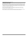
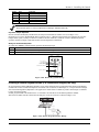
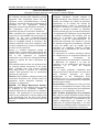
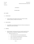
Common Lobby Logic
When an installation consists of a partition shared by users of other partitions in a building, that shared partition may
be assigned as the "common lobby" partition for the system (program field 1*17). An example of this might be in a
medical building where there are two doctors’ offices and a common entrance area (see example that follows
explanation).
2-1
FA1670C/FA1700C Installation and Setup Guide
The Common Lobby feature employs logic for automatic arming and disarming of the common lobby. Two programming
fields determine the way the common lobby will react relative to the status of other partitions. They are: 1*18 Affects
Lobby and 1*19 Arms Lobby.
1*18
Affects Lobby (must be programmed by partition)
Setting this field to 1 for a specific partition causes that partition to affect the operation of the common lobby as follows:
a. When the first partition that affects the lobby is disarmed, the lobby is automatically disarmed.
b. The common lobby cannot be armed unless every partition selected to affect the lobby is armed.
1*19
Arms Lobby (must be programmed by partition)
Setting this field to 1 for a specific partition causes that partition to affect the operation of the common lobby as follows:
a. The common lobby cannot be armed unless every partition selected to affect the lobby is armed.
b. Arming a partition that is programmed to arm the lobby causes the system to automatically attempt to arm the
lobby. If any faults exist in the lobby partition, or if another partition that affects the lobby is disarmed, the lobby
cannot be armed, and the message "UNABLE TO ARM LOBBY PARTITION" is displayed.
You cannot select a partition to "arm" the lobby unless it has first been selected to "affect" the lobby. Do not enable
field 1*19 without enabling field 1*18.
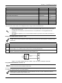
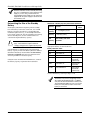
The following chart sums up how the common lobby partition will operate.
1*18
Affects Lobby
1*19
Arms Lobby
0
Disarms when
partition disarms?
0
Attempts to arm
when partition
arms?
NO
Can be armed if
other partitions
disarmed?
NO
YES
1
0
YES
NO
NO
1
1
YES
YES
NO
0
1
---ENTRY NOT ALLOWED---
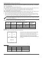
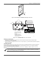
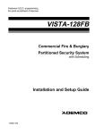
Example
Here is an example of how the lobby would react in a typical setup.
User #1 has access to Office #1 and the Common Lobby.
OFFICE 1
User #2 has access to Office #2 and the Common Lobby.
Office #1 is set up to affect the Common Lobby, but not arm it.
Office #2 is set up to affect and arm the Common Lobby.
NOTE: In the tables below, the notations in parentheses ( )
indicate the current status of the other partition when the user
takes action.
OFFICE 2
COMMON LOBBY
MAIN ENTRANCE
V128BP-001-V0
Sequence #1:
2-2
Office 1
Office 2
Lobby Action
User #1:
Disarms
(Armed)
Disarms
User #2:
(Disarmed)
Disarms
No Change
User #1:
Arms
(Disarmed)
No change
User #2:
(Armed)
Arms
Arms
Section 2 – Partitioning
Sequence #2:
Office 1
Office 2
Lobby Action
User #2:
(Armed)
Disarms
Disarms
User #1:
Disarms
(Disarmed)
(No change)
User #2:
(Disarmed)
Arms
No Change
User #1:
Arms
(Armed)
No Change
Notice that in sequence #1, because Office #2 was the last to arm, the lobby also armed (Office #2 is programmed to
affect and arm the lobby). In sequence #2, the lobby could not arm when Office #2 armed, because Office #1, which
affects the lobby, was still disarmed.
When Office #1 armed, the lobby still did not arm because Office #1 was not programmed to arm the lobby. User #1
would have to arm the lobby manually. Therefore, you would want to program a partition to affect and arm the lobby if
the users of that partition are expected to be the last to leave the building.
Do not assign partition 1 as the common lobby if fire zones are being used in the system. All fire zones must be
assigned to partition 1 to ensure all Fire Test modes operate correctly.
How User Access Codes Affect the Common Lobby
Codes with Global Arming
If a code is given "global arming" when it is defined (see the SECTION 9: User Access Codes), the keypad prompts the
user to select the partitions they want to arm. Only the partitions the user has access to are displayed. This allows the
user to choose the partitions to be armed or disarmed, and so eliminates the "automatic" operation of the lobby. Keep in
mind, however, that if a user attempts to arm all, and another "affecting" partition is disarmed, the user cannot arm the
lobby, and the message "UNABLE TO ARM LOBBY PARTITION" is displayed.
Codes with Non-Global Arming
If a user arms with a non-global code, the lobby partition operation is automatic, as described by fields 1*18 and 1*19.
Other Methods of Arming/Disarming
Common Lobby logic remains active when arming or disarming a partition that affects and/or arms the common lobby in
one of the following manners:
•
Quick-Arm
•
Keyswitch
•
Wireless Button
•
Wireless Keypad
Arming/Disarming Remotely
If a user arms or disarms remotely (through Compass downloading software), the lobby does not automatically follow
another partition that is programmed to arm or disarm the lobby. The lobby must be armed separately, after arming all
affecting partitions first.
Auto-Arming/Disarming
If scheduling is used to automatically arm and/or disarm partitions, the common lobby partition does not
automatically follow another partition that is programmed to arm or disarm the lobby. The lobby partition
must be scheduled to arm/disarm and must be scheduled as the last partition to arm.
If you are using auto-arming, make sure that the Auto-Arm Delay and Auto-Arm Warning periods, for the lobby
partition, (fields 2*05 and 2*06) combined are longer than that of any other partition that affects the lobby. This
causes the lobby to arm last.
Master Keypad Setup and Operation
Although this system has eight actual partitions, it provides an extra partition strictly for the purpose of assigning
keypads as Master keypads for the system.
Assigning any keypad to Partition 9 in Device Programming in the #93 Menu Mode makes that keypad a Master keypad.
A Master keypad reflects the status of the entire system (Partitions 1-8) on its display at one time. This is useful
because it eliminates the need for a building security officer to have to log on to various partitions from one partition's
keypad to find out where an alarm has occurred.
UL
In Commercial Fire installations, field 2*18 (Log on from other partitions) must be disabled for partition 1.
2-3
FA1670C/FA1700C Installation and Setup Guide
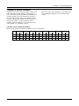
The following is a typical display:
SYSTEM 12345678
STATUS RRNNA ✴B
Possible status indications include:
A = Armed Away
S = Armed Stay
M = Armed Maximum
C = Comm Fail
I = Armed Instant
R = Ready
N = Not Ready
B = Bypassed/Ready
✴ = Alarm
T = Trouble
F = Fire Alarm
P = AC Power Failure
L = Low System Battery
To obtain more information regarding a particular partition, enter [✴] + Partition No. (e.g., [✴] + [4]). This allows
viewing only of that partition. In order to affect that partition, the user must use a code that has access to that
partition. Also, in order for a user of any partition to log on to Partition 9 to view the status of all partitions, that user
must have access to all partitions. Otherwise, access is denied.
The following is displayed for a fault condition on Zone 2 (Loading Dock Window) on Partition 1 (Warehouse) when a
user logs on from a keypad on Partition 9:
WHSE DISARMED
HIT ✴ FOR FAULTS
Pressing [✴] causes the following display to appear at Partition 1's keypad(s):
FAULT 002 LOADING
DOCK WINDOW
Additional zone faults are displayed one at a time. To display a new partition's status, press [✴] + Partition No.
The Armed LED on a Master keypad is lit only if all partitions have been armed successfully. The Ready LED is lit only
if all partitions are "ready to arm." Neither LED is lit if only some partitions are armed and/or only some partitions are
ready.
Press [✴] + [0] or [✴] + [9] to return to the master partition. Otherwise, if no keys are pressed for 2 minutes, the system
automatically returns to the master partition
The sounder on a Master keypad reflects the sound of the most critical condition on all of the partitions. The priority of
the sounds, from most to least critical, is as follows:
1. Pulsing fire alarm sounds
2. Steady burglar alarm sounds
3. Trouble sounds (rapid beeping)
Silence the sounder by pressing any key on the Master keypad or a keypad on the partition where the condition exists.
A Master keypad uses the same panics as Partition 1. Master keypad panics are sent to Partition 1, and will activate
on Partition 1. Therefore, panics must be programmed for Partition 1.
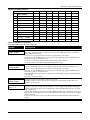
Priority of Displays for Multi-Partition
This table shows the priority of displays if more than one of these conditions exists at the same time.
Priority
Display
Priority
Fire Alarm
F
8
Not Ready
N
2
All Other Alarms
✴
9
Ready
R
3
AC Loss
P
10
Armed STAY
S
4
Comm Fail
C
11
Armed AWAY
A
5
System Low Battery
L
12
Armed INSTANT
I
6
Trouble
T
13
Armed MAXIMUM
M
7
Bypass
B
1
2-4
Description
Description
Display
S E C T I O N
3
Installing the Control
• • • • • • • • • • • • • • • • • • • • • • • • • • • • • • • • • • • • • • • • • • • • • • • • •
This section describes the procedures for mounting and wiring the control panel and all the peripheral devices.
NOTE: All references in this manual for number of zones, number of user codes, and the event log capacity, use the
FA1700C’s features. See SECTION 1: General Description for the table listing the differences between the FA1670C and
the FA1700C control panels.
Mounting the Control Cabinet
To mount the control cabinet, perform the following steps:
Step
Action
1
Before mounting the circuit board, remove the metal knockouts for the wiring entry that you will be using.
DO NOT ATTEMPT TO REMOVE THE KNOCKOUTS AFTER THE CIRCUIT BOARD HAS BEEN
INSTALLED.
2
Using fasteners or anchors (not supplied), mount the control cabinet to a sturdy wall in a clean, dry area
that is not readily accessible to the general public. The back of the cabinet has 4 holes for this purpose.
UL
To provide certificated burglary service for UL installations, refer to the special requirements and Figure 3-2. Cabinet
Attack Resistance Considerations to follow.
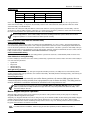
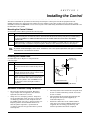
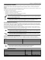
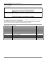
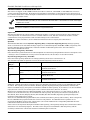
Installing the Cabinet Lock
RETAINER CLIP
(NOTE POSITION)
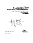
To install the lock, see Figure 3-1 and perform the
following steps:
Action
1
Remove cabinet door, then remove the lock
knockout from the door. Insert the key into the
lock.
2
Position the lock in the hole, making certain
that the latch will make contact with the latch
bracket when the door is closed.
3
When correctly positioned, insert supplied lock
clip on the inside of the cabinet into the slots
on the lock cylinder. Use an ADEMCO Lock
No. N6277V1 and Lock Clip No. P3422-2
(supplied
LOCKED
RETAINER
SLOTS
RETAINER
CLIP
UNLOCKED
CABINET DOOR BOTTOM
cab_lock_clip-001-V0
Step
Figure 3-1: Installing the Lock
Mercantile Premises Listing Guidelines
•
•
The panel door must be supervised. Mount the
clip-on tamper switch (supplied) to the cabinet's
right side wall and wire it to zone 6.
Assign zone 6 to a burglary partition. Program it
for day trouble/night alarm (zone type 5) when only
one burglary partition is used. Program it for 24hr. audible alarm (zone type 7) when more than one
burglary partition is used. Enable field 3*17 so
that the system responds to a ground fault in
accordance with its zone type rather than a ground
fault response.
•
•
•
All wiring between the transformer and panel must
be run in conduit. Remaining wires do not need to
be run in conduit.
All unused knockouts must be plugged using the
disc plugs and carriage bolts (supplied), as
indicated in Figure 3-2.
Fasten the cabinet door to the cabinet backbox
using the 15 one-inch-long Phillips-head screws
(supplied) after all wiring, programming, and
checkout procedures have been completed.
3-1
FA1670C/FA1700C Installation and Setup Guide
RUN BELL WIRES
IN CONDUIT
PLATE
PLUG THIS
KNOCKOUT
PC
BOARD
TO PLUG AN UNUSED KNOCKOUT OPENING,
REMOVE KNOCKOUT AND INSTALL A PAIR OF
DISC PLUGS AND A CARRIAGE BOLT AS SHOWN.
CABINET
DISC PLUGS (DIMPLES IN DISC
PLUG SHOULD REGISTER INSIDE
KNOCKOUT OPENING)
KNOCKOUT
OPENING
CARRIAGE BOLT
PLUG THESE
KNOCKOUTS
MOUNTING
SCREWS
(3)
HEX NUT AND
WASHER
PLUG THIS
KNOCKOUT
CABINET SIDE WALL
(OUTSIDE)
RUN ALL REMAINING
WIRE THROUGH HERE
PLUG THIS
KNOCKOUT
fire_burg_cab-001-V0
Figure 3-2: Cabinet Attack Resistance Considerations
Mercantile Safe and Vault Listing Guidelines
•
Follow the guidelines given above for Mercantile
Premises listing.
•
For safe and vault installations, a shock
sensor (not supplied) that is Listed for
protection of sheet metal enclosures, as well
as an additional Listed tamper switch, must
be installed on the cabinet backbox to protect
the cabinet from being removed from the wall.
These devices must also be connected to zone
6.
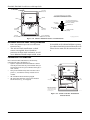
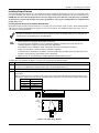
Commercial Fire Guidelines
For Commercial Fire installations, the following
requirements apply (See Figure 3-3).
•
System components mounted inside the cabinet
must be placed so that all power-limited wiring is
separated from all non-power-limited wiring by ¼inch (6.4mm).
•
Non-power-limited wiring that exits the control
panel (i.e., transformer wiring) must be run in
conduit.
•
All unused knockouts must be plugged.
•
All wiring that exits the control panel must be
strain-relieved (e.g., tie-wrapped).
TELCO
LINE
PLATE
PC
BOARD
TIE WRAPS
TIE WRAPS
WIRES MUST BE
RUN IN CONDUIT
ZONE
WIRING
FROM
TRANSFORMER
TIE WRAPS
NOTE: ALL POWER-LIMITED
WIRING MUST BE SEPARATED
FROM NON-POWER LIMITED
AND HIGH VOLTAGE WIRING
BY 1/4-INCH (6.4 mm)
BATTERY
BATTERY
fire_burg_cab-003-V0
Figure 3-3: Commercial Fire Installation
Considerations
3-2
Section 3 - Installing the Control
NOTES:
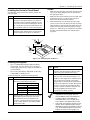
Installing the Control's Circuit Board
•
To install the circuit board in the cabinet, perform the
following steps:
•
Step
Action
1
Confirm the Mounting Plate is installed
securely in the cabinet (Figure 3-4, Detail A).
Install the nylon standoffs (supplied) into the
top corner holes of the mounting plate (Detail
B.) Insert the top of the circuit board onto the
two standoffs at the top of the mounting plate.
2
Make sure that the tabs on the side of the plate did
not pop out during shipping and are inserted into
the appropriate slots.
Make sure that the mounting screws are tight. This
ensures that there is a good ground connection
between the PC board and the cabinet.
Dress field wiring away from the microprocessor
(center) section of the PC board. Use the mounting
plate brackets on the left and right sidewalls of the
cabinet for anchoring field wiring using tie wraps
(Figure 3-3). These steps are important to minimize
the risk of panel RF interference with television
reception.
•
Place the board flat and secure to the
mounting plate with the three accompanying
screws and spacers as shown in (Detail C.)
CABINET
PLATE
DETAIL B
INSTALLING
NYLON STANDOFFS (2)
CABINET
PLATE
CABINET
PLATE
PC BOARD
MOUNTING
SCREW
DETAIL A
SIDE VIEW
OF
ATTACHMENT
SPACER
DETAIL C
SIDE VIEW,
PC BOARD INSTALLATION
USING SPACERS (3) AND
MOUNTING SCREWS (3)
fire_burg_cab-002-V1
Figure 3-4: Mounting the PC Board
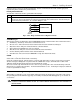
Installing the Keypads
•
Up to 31 addressable keypads (addresses 00-30)
may be used. You may need to use an auxiliary
power supply if the 1A aux. output is exceeded (for
Canada 650mA).
•
Use a 2-line alpha display, FA570CR (for fire only)
or FA570KP (for burglary only).
To wire the keypads, perform the following steps:
Step
Action
1
Determine wire gauge by referring to the
Wire Run Length/Gauge table below.
Wire Run Length/Gauge Table
Wire Gauge
Length
#22 gauge
450 feet
#20 gauge
700 feet
#18 gauge
1100 feet
#16 gauge
1750 feet
2
Wire keypads to a single wire run or connect
individual keypads to separate wire runs.
The maximum wire run length from the
control to a keypad, which is homerun back
to the control, must not exceed the lengths
listed in the table.
Step
Action
3
Run field wiring from the control to the
keypads (using standard 4-conductor cable
of the wire gauge determined in step 1).
4
Connect keypad(s) to terminals 11, 12, 13,
and 14 on the control board, see Figure 3-5.
NOTE: In a Fire Application and when using
only one keypad, it must be connected to
Keypad Port 2, and must be mounted within
20 feet of the cabinet in conduit. The keypad
on Port 2 is electrically isolated from those
on Port 1 and will continue to function even
if wiring problems prevent the other
keypads from working properly.
•
•
The length of all wire runs combined,
regardless of the wire gauge, must not
exceed 2000 feet when unshielded quad
conductor cable is used (1000 feet if
unshielded cable is run in conduit, which
acts a shield, or if shielded cable is used).
If more than one keypad is wired to one run,
then the above maximum lengths must be
divided by the number of keypads on the run
(e.g., the maximum length is 225 feet if two
keypads are wired on a #22 gauge run).
3-3
FA1670C/FA1700C Installation and Setup Guide
RED
11
system's program. Each keypad must be set for a
different address.
BLACK
12
13
kypd_conn-001-V0
YELLOW
14
• Do not set any keypads to address 31
(nonaddressable mode). They will interfere
with other keypads (as well as other devices)
connected to the keypad terminals.
• If an “OC” or “OPEN CIRCUIT” message is
present on a keypad, data from the control is
not reaching the keypad. Please check your
wiring.
KEYPADS
GREEN
CONTROL
TERMINALS
Figure 3-5: Keypad Connections to Control Panel
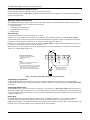
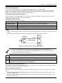
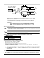
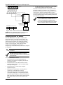
Commercial Fire Requirements
For commercial fire installations, the primary fire
keypad must be installed on panel Keypad Port 2 and
mounted within 20 feet of the control panel. External
wiring must be run in conduit.
Additionally, you can install supplemental fire keypads
and devices on ECP Port 1, using an ECP Isolator to
separate all fire wiring from all burglary wiring (see
Figure 3-6).
V1 Out (Red)
V2 Out (Red)
TO
BURGLARY
DEVICES
GND (Black-)
G (Green)
Y (Yellow)
ECP ISOLATOR
TB1
1
V1 Out (500ma)
2
V2 Out (500ma)
3
GND
4
G
5
Y
1
2
3
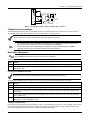
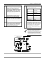
Supplementary Power Supply for Additional Keypads
When the control’s auxiliary power load for all devices
exceeds 1A, you can power additional keypads from a
regulated 12VDC power supply. Use a UL Listed,
battery-backed supply for UL installations. For fire
applications, the power supply must be UL1481 Listed.
Connect the additional keypads as shown in Figure 3-7,
using the keypad wire colors shown. Be sure to observe
the current ratings for the power supply used.
For UL commercial fire and burglary
installations, no more than one wire per
terminal may be connected.
Use only 14-22AWG wire.
UL
4
12V (Red +)
+
TO
FIRE
DEVICES
+
–
GRN
GND (Black -)
YEL
G (Green)
SUPPLEMENTARY
POWER SUPPLY
–
+
TO FIRE DEVICES
GRN
TO BURG DEVICES
YEL
–
YEL
+
GRN
ECPISO-001-V0
Figure 3-6. ECP Isolator Wiring
–
+
Addressing the Keypads
TO BURG DEVICES
The keypads will not operate until they are
physically addressed and enabled in the
system's Device Programming in the #93 Menu
Mode.
Set each keypad for an individual address (00-30)
according to the keypad's instructions. Set an alpha
keypad for address 00 and other keypads for higher
addresses (00 and 01 are enabled in the system's
default program). Any keypads set for address 02 and
above will appear blank until they are enabled in the
3-4
pwr_sup_conn-010-V0
Y (Yellow)
TO KEYPAD YEL WIRE
IN
ECP ISOLATOR
–
TO KEYPAD GRN WIRE
–
OUT
SUPPLEMENTARY
POWER SUPPLY
AUX. AUX. DATA DATA
+ – IN OUT
11 12
13
14
TO KEYPAD BLK WIRE
+
GRN
14
Y (Yellow)
13
G (Green)
12
GND (Black -)
12V (Red +)
11
CONTROL TERMINAL STRIP
YEL
IMPORTANT:
MAKE CONNECTIONS
DIRECTLY TO SCREW
TERMINALS AS SHOWN.
MAKE NO CONNECTION
TO THE KEYPAD BLUE
WIRE (IF PRESENT).
PANEL KEYPAD PORT
TO KEYPAD RED WIRE
G (Green)
• Make connections directly to the screw
terminals as shown in Figure 3-7. Make no
connection to the keypad blue wire (if
present).
• Be sure to connect the negative (–) terminal
on the power supply unit to terminal 7 (–) on
the control.
Y (Yellow)
GND (Black)
+12V In (Red)
TB2
TO FIRE DEVICES
BURG DEVICES
FIRE DEVICES
Figure 3-7. Using a Supplementary Power Supply
Section 3 - Installing the Control
Installing External Sounders
The FA1670C/FA1700C provides two Notification Appliance Circuits for operating fire and burglary alarm notification
appliances. Each circuit is rated as Special Application for Fire and 10VDC – 14VDC, 1.7A max. power-limited for
Burglary.
NOTE: The total alarm current drawn from Auxiliary Power 1, Auxiliary Power 2, polling loop, Bell 1, and Bell 2 cannot
exceed 2.3A (for Canada 1.95A) for battery-independent operation.
The outputs have the following options:
•
Selectable to activate by individual zone assignments
•
Selectable for confirmation of arming ding.
•
Selectable to chime when entry/exit or perimeter zones are faulted.
•
Selectable for no timeout or timeout of 2-30 minutes.
You may use a Commercial Fire Listed 24VDC Power Supply to convert one or both FA1670C/FA1700C 12VDC,
1.7A style-Y supervised Special Application Notification Appliance Circuits to 24V, style-Y supervised, Special
Application Notification Appliance Circuits.
UL
•
•
Burglary Notification Appliance Circuits must be programmed for a timeout of 16 minutes or longer.
Commercial fire alarm systems require Notification Appliance Circuits to be supervised.
Notification Appliance Circuit Supervision
The FA1670C/FA1700C monitors the Notification Appliance Circuits wiring for open and short circuit faults while the
output is inactive. The system provides a trouble indication (Zone 970 Bell 1; 971 Bell 2) when an open occurs. When a
short occurs between the Bell (+) and Bell (-) terminal wiring, or between the Bell (+) terminal wiring and earth ground
the system provides a trouble indication (972 Earth Ground).
The FA1670C/FA1700C indicates the trouble condition regardless of whether the system is armed or disarmed. The
zone displays on the keypads, reports to the event log, and transmits to the central station (if programmed) on Partition
1. The trouble is cleared from the display by entering the user code + OFF.
UL
•
•
Use only UL Listed sounding devices for UL installations.
In Commercial Fire installations, the 4204CF cannot be used to drive sounders in the same audible area as
sounders connected to the alarm outputs of the control panel.
For ULC fire installations, alarm indicating devices must not be connected to the fire transmitter. These
devices must be connected to the Fire Alarm Control Panel.
ULC
Synchronization Requirements for Commercial Fire
Notification Appliance Circuit outputs must be wired to a Sync Module if more than one device is used. Follow
instructions provided with Sync Module. Be sure to use the compatible Sync Module for the Alarm Indicating Device
selected.
MANUFACTURER
GENTEX
SYNC MODULE MODEL NUMBER
AVSM
SYSTEM SENSOR
MDL
WHEELOCK
DSM
UL
•
•
All visual notification appliances within the same physical area must be synchronized.
The bell outputs are listed as Special Application Notification Appliance Circuits.
Compatible Alarm Indicating Devices
ALARM INDICATING DEVICE TYPE
UL listed Grade A Bell in Housing
RX7 UL Indoor Sounder, 12V
Horn Strobe 2w
Horn Strobe 2w
Horn Strobe 4w
Horn Strobe 4w
MANUFACTURER
Honeywell/ADEMCO
ADT
GENTEX
GENTEX
GENTEX
GENTEX
MODEL #
AB12M
875936B
GEC3-12, GES3-12, GEH-12
GEC3-12, GES3-12, GEH-12
GEC3-12, GES3-12, GEH-12
GEC3-12, GES3-12, GEH-12
3-5
FA1670C/FA1700C Installation and Setup Guide
ALARM INDICATING DEVICE TYPE
Chime, 12/24V, Selectable Tone & Volume, Red
Chime, 12/24V, Selectable Tone & Volume, White
Chime/Strobe, 12/24V, Selectable Candela, Tone & Volume, Red
Chime/Strobe, 12/24V, Selectable Candela, Tone & Volume, White
Horn, 12/24V, Red
Horn, 12/24V, White
Horn, 12/24V, Outdoor, Red
2-Wire Wall Mount Horn/Strobe, 12/24V, Standard Candela, Red
2-Wire Wall Mount Horn/Strobe, 12/24V, High Candela, Red
2-Wire Wall Mount Horn/Strobe, 12/24V, Standard Candela, Red, Outdoor
2-Wire Wall Mount Horn/Strobe, 12/24V, High Candela, Red, Outdoor
2-Wire Wall Mount Horn/Strobe, 12/24V, Standard Candela, White
2-Wire Wall Mount Horn/Strobe, 12/24V, High Candela, White
4-Wire Wall Mount Horn/Strobe, 12/24V, Standard Candela, Red
4-Wire Wall Mount Horn/Strobe, 12/24V, High Candela, Red
4-Wire Wall Mount Horn/Strobe, 12/24V, Standard Candela, Red, Outdoor
4-Wire Wall Mount Horn/Strobe, 12/24V, High Candela, Red, Outdoor
4-Wire Wall Mount Horn/Strobe, 12/24V, Standard Candela, White
4-Wire Wall Mount Horn/Strobe, 12/24V, High Candela, White
2-Wire Ceiling Mount Horn/Strobe, 12/24V, Standard Candela, Red
2-Wire Ceiling Mount Horn/Strobe, 12/24V, High Candela, Red
2-Wire Ceiling Mount Horn/Strobe, 12/24V, Standard Candela, Red, Outdoor
2-Wire Ceiling Mount Horn/Strobe, 12/24V, High Candela, Red, Outdoor
2-Wire Ceiling Mount Horn/Strobe, 12/24V, Standard Candela, White
2-Wire Ceiling Mount Horn/Strobe, 12/24V, High Candela, Red
4-Wire Ceiling Mount Horn/Strobe, 12/24V, Standard Candela, Red
4-Wire Ceiling Mount Horn/Strobe, 12/24V, High Candela, Red
4-Wire Ceiling Mount Horn/Strobe, 12/24V, Standard Candela, Red, Outdoor
4-Wire Ceiling Mount Horn/Strobe, 12/24V, High Candela, Red, Outdoor
4-Wire Ceiling Mount Horn/Strobe, 12/24V, Standard Candela, White
4-Wire Ceiling Mount Horn/Strobe, 12/24V, High Candela, White
2-Wire Wall Mount Strobe, 12/24V, Standard Candela, Red
2-Wire Wall Mount Strobe, 12/24V, High Candela, Red
Wall Mount Strobe, 12/24V, Standard Candela, Red, Outdoor
Wall Mount Strobe, 12/24V, High Candela, Red, Outdoor
Wall Mount Strobe, 12/24V, Standard Candela, White
Wall Mount Strobe, 12/24V, High Candela, White
Ceiling Mount Strobe, 12/24V, Standard Candela, Red
Ceiling Mount Strobe, 12/24V, High Candela, Red
Ceiling Mount Strobe, 12/24V, Standard Candela, Red, Outdoor
Ceiling Mount Strobe, 12/24V, High Candela, Red, Outdoor
Ceiling Mount Strobe, 12/24V, Standard Candela, White
Ceiling Mount Strobe, 12/24V, High Candela, White
Horn Strobe 12V, 4W
Horn Strobe 12V, 2W
Strobe 12V
Horn Strobe 12V, 2W
Horn 12V/24V
Horn 12V
Horn 12V/24V
Bell 12V
3-6
MANUFACTURER
SYSTEM SENSOR
SYSTEM SENSOR
SYSTEM SENSOR
SYSTEM SENSOR
SYSTEM SENSOR
SYSTEM SENSOR
SYSTEM SENSOR
SYSTEM SENSOR
SYSTEM SENSOR
SYSTEM SENSOR
SYSTEM SENSOR
SYSTEM SENSOR
SYSTEM SENSOR
SYSTEM SENSOR
SYSTEM SENSOR
SYSTEM SENSOR
SYSTEM SENSOR
SYSTEM SENSOR
SYSTEM SENSOR
SYSTEM SENSOR
SYSTEM SENSOR
SYSTEM SENSOR
SYSTEM SENSOR
SYSTEM SENSOR
SYSTEM SENSOR
SYSTEM SENSOR
SYSTEM SENSOR
SYSTEM SENSOR
SYSTEM SENSOR
SYSTEM SENSOR
SYSTEM SENSOR
SYSTEM SENSOR
SYSTEM SENSOR
SYSTEM SENSOR
SYSTEM SENSOR
SYSTEM SENSOR
SYSTEM SENSOR
SYSTEM SENSOR
SYSTEM SENSOR
SYSTEM SENSOR
SYSTEM SENSOR
SYSTEM SENSOR
SYSTEM SENSOR
WHEELOCK
WHEELOCK
WHEELOCK
WHEELOCK
WHEELOCK
WHEELOCK
WHEELOCK
WHEELOCK
MODEL #
CHR
CHW
CHSR
CHSW
HR
HW
HRK
P2R
P2RH
P2RK
P2RHK
P2W
P2WH
P4R
P4RH
P4RK
P4RHK
P4W
P4WH
PC2R
PC2RH
PC2RK
PC2RHK
PC2W
PC2WH
PC4R
PC4RH
PC4RK
PC4RHK
PC4W
PC4WH
SR
SRH
SRK
SRHK
SW
SWH
SCR
SCRH
SCRK
SCRHK
SCW
SCWH
MT-121575W
AS-121575W
RSS-121575W
NS-121575W
NH-12/24
AH-12
MT-12/24, MT4-12/24
MB-G6-12, MB-G10-12
Section 3 - Installing the Control
Table 3-1: BELL 1 AND BELL 2 MAXIMUM DEVICE RATING
NOTE: To use this table, the device Candela Setting and Horn Setting MUST match what is listed in
the Table.
Mfg
Gentex
Gentex
Gentex
Gentex
System Sensor
System Sensor
System Sensor
System Sensor
System Sensor
System Sensor
System Sensor
System Sensor
System Sensor
System Sensor
System Sensor
System Sensor
System Sensor
System Sensor
System Sensor
System Sensor
System Sensor
System Sensor
System Sensor
System Sensor
System Sensor
System Sensor
System Sensor
System Sensor
System Sensor
System Sensor
System Sensor
System Sensor
System Sensor
System Sensor
System Sensor
System Sensor
System Sensor
System Sensor
System Sensor
System Sensor
System Sensor
System Sensor
System Sensor
Wheelock
Wheelock
Wheelock
Wheelock
Wheelock
Wheelock
Wheelock
Wheelock
Bell
Alarm Indicating
Device Type
Horn Strobe 12V, 2w
Horn Strobe 12V, 2w
Horn Strobe 12V, 4w
Horn Strobe 12V, 4w
Horn, Strobe12/24V
Horn, Strobe12/24V
Horn, Strobe12/24V
Horn, Strobe12/24V
Horn, Strobe12/24V
Horn, Strobe12/24V
Horn, Strobe12/24V
Horn, Strobe12/24V
Horn, Strobe12/24V
Horn, Strobe12/24V
Horn, Strobe12/24V
Horn, Strobe12/24V
Horn, Strobe12/24V
Horn, Strobe12/24V
Horn, Strobe12/24V
Horn, Strobe12/24V
Horn, Strobe12/24V
Horn, Strobe12/24V
Horn, Strobe12/24V
Horn, Strobe12/24V
Horn, Strobe12/24V
Horn, Strobe12/24V
Horn, Strobe12/24V
Horn, Strobe12/24V
Horn, Strobe12/24V
Horn, Strobe12/24V
Horn, Strobe12/24V
Strobe12/24V
Strobe12/24V
Strobe12/24V
Strobe12/24V
Strobe12/24V
Strobe12/24V
Strobe12/24V
Strobe12/24V
Strobe12/24V
Strobe12/24V
Strobe12/24V
Strobe12/24V
Horn Strobe 12V, 4W
Horn Strobe 12V, 2W
Strobe 12V
Horn Strobe 12V, 2W
Horn 12V/24V
Horn 12V
Horn 12V/24V
Bell 12V
Bell 12V
Model
GEC3-12,GES3-12,GEH-12
GEC3-12,GES3-12,GEH-12
GEC3-12,GES3-12,GEH-12
GEC3-12,GES3-12,GEH-12
HR
HW
HRK
P2R
P2RH
P2RK
P2RHK
P2W
P2WH
P4R
P4RH
P4RK
P4RHK
P4W
P4WH
PC2R
PC2RH
PC2RK
PC2RHK
PC2W
PC2WH
PC4R
PC4RH
PC4RK
PC4RHK
PC4W
PC4WH
SR
SRH
SRK
SRHK
SW
SWH
SCR
SCRH
SCRK
SCRHK
SCW
SCWH
MT-121575W
AS-121575W
RSS-121575W
NS-121575W
NH-12/24
AH-12
MT-12/24,MT4-12/24
MB-G6-12,MB-G10-12
AB12M
Candela
Setting
15
75
15
75
15
15
15
15
15
15
15
15
15
15
15
15
15
15
15
15
15
15
15
15
15
15
15
15
15
15
15
15
15
15
15
15
15
15
15
15
15
15
15
15
na
na
na
na
na
Horn Setting
Mech-Temporal
Mech-Temporal
Continuous Mech
Continuous Mech
Temporal - High
Temporal - High
Temporal - High
Temporal - High
Temporal - High
Temporal - High
Temporal - High
Temporal - High
Temporal - High
Temporal - High
Temporal - High
Temporal - High
Temporal - High
Temporal - High
Temporal - High
Temporal - High
Temporal - High
Temporal - High
Temporal - High
Temporal - High
Temporal - High
Temporal - High
Temporal - High
Temporal - High
Temporal - High
Temporal - High
Temporal - High
Temporal - High
Temporal - High
Temporal - High
Temporal - High
Temporal - High
Temporal - High
Temporal - High
Temporal - High
Temporal - High
Continuous/Hi
Continuous/Hi
na
Hi
Hi
Hi
Continuous Horn
na
na
Max # of
Devices
6
2
6
2
38
38
38
10
10
10
10
10
10
10
10
10
10
10
10
10
10
10
10
10
10
10
10
10
10
10
10
10
10
10
10
10
10
10
10
10
10
10
10
4
6
6
7
80
9
10
9
9
3-7
FA1670C/FA1700C Installation and Setup Guide
Supervising the Notification Appliance Circuits
To wire the NAC using the supervision feature, perform the following:
Install a 2K EOL resistor (Model 2EOL, supplied) across the last notification appliance on each Notification Appliance
Circuit to be supervised.
Auxiliary Relay Connections
The FA1670C/FA1700C provides a built-in Form C relay with contacts rated at 28VAC/VDC, 2.8A. The relay may be
programmed (field 3✳ 61) for one of the following functions:
•
Alarm Activation
•
Trouble/Supervisory Activation
•
4-Wire Smoke Detector Reset
•
Battery Saver
Alarm Activation
(3✳ 61 = 1 or 4) Steady activation in response to an alarm.
If field 3✳ 61 = 1, the auxiliary relay remains active until Aux. Relay Timeout expires or until User Code + OFF is
entered. This option can be used to provide an unsupervised Notification Appliance Circuit for supplementary strobes,
sounders, etc. when wired to the Aux Power 1 or a separate power supply, see Figure 3-8.
If field 3✳ 61 = 4, the auxiliary relay remains activated until User Code + # + 67 is entered. By default, the relay is set
to activate on alarm zones 1-8 with no timeout (field 3✳ 61 = 1).
When field 3✳61 = 1, the auxiliary relay can be programmed to give a brief activation for confirmation of arming ding
(field 3✳ 57) or Chime Mode (field 3✳ 59).
ALARM
8
9
10
11
12
GROUND
AUX PWR #1
N.C.
POLE
+
CAN DRAW POWER FROM
AUX. PWR. 1 OUTPUT OR
FROM SEPARATE SUPPLY.
belloutput-005-V0
NOTES:
USE NON-POLARIZED INDICATING DEVICES.
WIRING IS NOT SUPERVISED.
DO NOT EXCEED RATINGS OF THE SUPPLY USED.
IF AUX. PWR. 1 OUTPUT IS USED, THE COMBINED
ALARM CURRENT DRAIN FROM AUX. PWR. 2,
BELL 1, AND BELL 2 CANNOT EXCEED 2.3A MAX.
7
N.O.
AUX RELAY FACTORY DEFAULTS
ACTIVATES FOR ZONES 1-8 ALARMS
(STEADY ALARM OUTPUT).
NO TIMEOUT.
Figure 3-8: Wiring Auxiliary Relay for Alarm Activation
Trouble/Supervisory Activation
(3✳ 61 = 0) Steady activation in response to any zone or system related trouble condition or to any fire supervisory
condition. The auxiliary relay remains activated until all fault conditions have been corrected and a User Code + OFF
is entered.
4-Wire Smoke Detector Reset
(3✳ 61 = 2) Momentary (8-second) activation in response to a second entry of a User Code + OFF sequence following a
fire alarm condition. This interrupts power to 4-wire smoke detectors connected to hardwired zones 1-8 and polling loop
zones, allowing the detectors to be reset. Power to the detectors should be wired to the auxiliary relay and to Aux. Power
1 output, see Figure 3-9.
Battery Saver
(3✳61 = 3) When this option is selected, the auxiliary relay is normally activated (e.g., N.O. and pole contacts are
connected) and de-activates 4 hours after the start of AC Loss. Using this feature, non-critical loads, such as
supplementary keypads, can be disconnected from the auxiliary power outputs, allowing a smaller capacity battery to be
used. The relay re-activates within a few seconds after the AC power restores.
3-8
Section 3 - Installing the Control
N.O.
7
POLE
8
N.C.
Aux. Pwr 1
AUXILIARY RELAY
+
9
10
+
11
Keypad Prt 1 12
BLK
-
4-WIRE SMOKE
DETECTORS
+
+
-
-
–
•
•
+
EOL
POWER
SUPERVISION
RELAY
MODULE
EOLR-1
CONTROL
PANEL
SHOWN POWERED.
RELAY OPENS WHEN
POWER IS LOST
ZONE
TERMINALS
(15-27)
+
HEAT
DETECTOR
2000
OHM
EOLR
4_wiresmk-005-V0
Figure 3-9: Wiring Auxiliary Relay for Smoke Detector Reset
Telephone Line Connections
The FA1670C/FA1700C provides one main built-in dialer for communication to the central station and one optional
5140DLM Backup Dialer, both supervised for voltage and current on the phone lines.
Do not connect the system to telephone lines that require ground start service.
•
UL
•
•
For Listed fire central station (UL864/NFPA 72) applications, use communications device 7845i-ent alone,
the main dialer with the 7845i-ent or use the main dialer with the 5140DLM.
For listed fire remote station (UL864/NFPA 72) applications, use the main dialer with the 5140DLM.
Telephone line supervision is required for commercial fire alarm systems.
Main Dialer Connections
ULC The 5140DLM Backup Dialer cannot be used for ULC fire installations.
To connect the main dialer, refer to the Summary of Connections diagram and perform the following steps:
Step
Action
1
Connect the main dialer to the telephone company lines using the RJ31X cable supplied.
2
If the dialer output is connected to telephone lines that have a telephone company MTU installed, cut the
blue jumper (W6).
Installing the 5140DLM Backup Dialer
Do not connect the main dialer and the backup dialer to the same telephone company line.
To install the 5140DLM, refer to the Summary of Connections diagram and perform the following steps:
Step
Action
1
Mount the 5140DLM to the main PC board shield.
2
Connect the backup dialer to the telephone company lines using the RJ31X cable supplied.
3
Connect the backup dialer to the J3 connector on the main PC board using the ribbon cable (supplied with
the module).
4
Connect the earth ground screw on the 5140DLM to the earth ground terminal (30) on the main PC board
using 16AWG wire.
5
If the dialer output is connected to telephone lines that have a telephone company MTU installed, cut the
blue jumper on the 5140DLM PC board.
Telephone Line Supervision
If the tip/ring voltage falls below approximately 25 volts (13 volts if the blue jumper is cut) or the handset current is less
than approximately 10mA, the supervision circuits for the dialer output will indicate a fault condition. Faults on the
phone lines are displayed as zones 974 (main dialer) and 975 (backup dialer).
3-9
FA1670C/FA1700C Installation and Setup Guide
•
•
To prevent risk of shock, disconnect the phone lines at the telco jack before servicing the panel.
If the communicator is connected to a telephone line inside a PABX, be sure the PABX has backup power
supply that can support the PABX for 24 hours (central station usage) or 60 hours (remote station usage).
Many PABXs are not power-backed up, and connection to such a PABX results in a communication failure if
power is lost.
•
Zone 974 (Primary Dialer Supervision) must be enabled in order for the backup dialer (or communications
device, if used) to communicate in the event that the primary dialer fails.
If a communications device is used as the primary dialer, then its supervisory zone must be enabled (e.g.
8XX, where XX is the device address of the communications device.
!
•
UL
The telephone line inputs have overvoltage protection in accordance with UL1459.
Reporting Formats
The system is shipped defaulted for Contact ID format. It is the only format capable of uniquely reporting all 250
zones, as well as openings and closings for all 250 users. This requires central stations to be equipped with the
ADEMCO 685 (using software level 4.10 or higher) or MX8000 receiver to fully support all new
FA1670C/FA1700C report codes. If you need to update your 685 or MX8000 receiver, contact your distributor.
The system supports ADEMCO Low Speed 3+1; 4+1; 4+2; Sescoa/Radionics 3+1; 4+1; 4+2; ADEMCO 4+2 Express;
ADEMCO High Speed; ADEMCO Contact ID Formats.
Dialer Operation
When only the main dialer is enabled (field 3✳30 = 1,0), the system attempts to route all messages over the main dialer
output. When both the main and backup dialers are enabled (field 3*30 = 1,1), the panel will Alternate Dialers by pairs
(make two attempts to report on the Main Dialer, then make two attempts to report on the Back Up dialer). The panel
will continue to do this to the Primary Phone number until it reaches its programmed attempts in 3*21, then it will do
the same to the Secondary phone number. Test Report is always sent on Alternating dialers.
The communicator makes up to 8 attempts to transmit the messages to one or both telephone numbers (primary and
th
secondary), depending on the report routing options programmed. After the 8 attempt, the communicator hangs up and
the system displays “COMM FAIL” on the keypad. The number of dialer attempts are programmed in field 3✳ 21 (default
= 8; must be restricted to 3, 4, or 5 if a secondary phone number is programmed).
Wiring Burglary and Panic Devices to Zones 1-8
The maximum zone resistance is 100 ohms for zones 1, 2 and 8, and 300 ohms for all other zones (excluding the
2K EOL resistor).
To wire burglary and panic devices to zones 1-8, connect sensors/contacts to the hardwire zone terminals (15 through
27). Connect N.C. and N.O. devices as follows:
•
Connect N.C. devices in series with the high (+) side of the loop. The 2K EOL resistor must be connected in series
with the devices, following the last device.
•
Connect N.O. devices in parallel (across) the loop. The 2K EOL resistor must be connected across the loop wires
at the last device.
Using 2-Wire Smoke Detectors on Zones 1 and 2
Zone 1 and 2 can support up to 16 2-wire smoke detectors each (32 total).
The alarm current on zones 1 and 2 supports only one smoke detector in the alarmed state.
When assigned zone type 9 or 16, the second entry of a User Code + off at a keypad interrupts power to these zones to
allow detectors to be reset following an alarm.
Compatible 2-Wire Smoke Detectors
For ULC fire installations, 2-Wire Smoke Detectors must not be connected to the fire transmitter. These devices
ULC must be connected to the Fire Alarm Control Panel.
3-10
Section 3 - Installing the Control
DETECTOR TYPE
MANUFACTURER
MODEL #
2-Wire Photoelectric Smoke Detector
DSC
FSA-210B
2-Wire Photoelectric Smoke Detector w/Heat Detector
DSC
FSA-210BT
2-Wire Photoelectric Smoke Detector
System Sensor
2W-B
2-Wire Photoelectric Smoke Detector w/Heat Detector
System Sensor
2-Wire Ionization Smoke Detector
System Sensor
2-Wire Photoelectric Low-Profile Smoke Detector
System Sensor
Access Reversal Relay/Sync Module
System Sensor
2WT-B
1451 w/B401B
base
2151 w/B401
base *
RRS-MOD
2-Wire Photoelectric Smoke Detector
ESL
521B
2-Wire Photoelectric Smoke Detector w/Heat Detector
ESL
521BXT
2-Wire Photoelectric Smoke Detector w/Heat Detector
ESL
429AT
* This model may not be used on zones designated as Zone Type 16: Fire with Verification.
•
UL
•
•
These smoke detectors are UL Listed for use with the FA1670C/FA1700C and are the only 2-wire smoke
detectors that may be used.
A combination of heat detectors and smoke detectors is not permitted on a zone programmed for fire
verification.
Fire installations require the use of a synchronization module to synchronize the sounders and strobes on
the system.
Wiring 2-Wire Smoke Detectors to Zones 1 and 2
2K EOL resistors must be used on fire zones and must be connected across the loop wires of each zone at the
last detector.
To wire 2-wire smoke detectors to zone 1 and/or zone 2, perform the following steps:
Step
Action
1
Select 2-wire smoke detectors from the list of compatible detectors.
2
Connect 2-wire smoke detectors across zone 1 (terminals 15 and 16), and/or zone 2 (terminals 17 and 18) as
shown in Figure 3-10. Observe proper polarity when connecting the detectors.
3
Connect the EOL resistor at the last detector in the loop across the zone 1 terminals. The EOL resistor
must be connected across the loop wires at the last detector.
ZONE 1
16
2_wiresmk-001-V0
SMOKE
2000 OHMS
EOLR
15
2-WIRE SMOKE
DETECTOR
Figure 3-10: 2-Wire Smoke Detector on Zone 1 (for zone 2 use terminals 17 and 18)
Using 4-Wire Smoke Detectors on Zones 1-8
For ULC fire installations, 4-Wire Smoke Detectors must not be connected to the fire transmitter. These devices
ULC must be connected to the Fire Alarm Control Panel.
You may use as many 4-wire smoke detectors as can be powered from the panel's Auxiliary Power output without
exceeding the output's rating (1A (for Canada 650mA)).
Auxiliary power to 4-wire smoke detectors is not automatically reset after an alarm, and therefore must be
momentarily interrupted using the auxiliary relay.
3-11
FA1670C/FA1700C Installation and Setup Guide
Compatible 4-Wire Smoke Detectors
Use any UL Listed 4-wire smoke detector that is rated for 12VDC operation and that has alarm reset time not exceeding
6 seconds. Some compatible 4-wire smoke detectors are listed below.
DETECTOR TYPE
MANUFACTURER
MODEL #
4-Wire Photoelectric Smoke Detector
DSC
FSA-410B
4-Wier Photoelectric Smoke Detector w/Heat Detector
DSC
FSA-410BT
4-Wire Photoelectric Smoke Detector w/Sounder & Heat Detector
DSC
FSA-410BST
4-Wire Photoelectric Smoke Detector w/Aux. Relay & Heat Detector
DSC
FSA-410BRT
4-Wire Photoelectric Smoke w/Aux. Relay, Sounder & Heat Detector
DSC
FSA-410BRST
End of Line Power Supervision Relay for FSA-410 Series Smoke Detectors
DSC
RM-2
Polarity reversal module for FSA-410 series Smoke Detectors
DSC
PRM-4WC
4-Wire Photoelectric Smoke Detector
System Sensor
4W-B
4-Wire Photoelectric Smoke Detector w/Heat Detector
System Sensor
4WT-B
4-Wire Photoelectric Smoke Detector w/Sounder & Heat Detector
System Sensor
4WTA-B
4-Wire Photoelectric Smoke Detector w/Aux. Relay & Heat Detector
System Sensor
4WTR-B
4-Wire Photoelectric Smoke Detector w/Aux. Relay, Sounder & Heat Detector
System Sensor
4WTAR-B
4-Wire Photoelectric Smoke Detector w/Aux. Relay, Sounder & Isolated Heat Detector
System Sensor
4WITAR-B
4-Wire Photoelectric Air Duct Smoke Detector, Extended Air Speed Range
System Sensor
DH100ACDCLP
4-Wire Ionization Air Duct Smoke Detector
System Sensor
DH100ACDCI
Wiring 4-Wire Smoke Detectors
UL
•
•
•
Power to 4-wire smoke detectors must be supervised with an EOL device (use a System Sensor EOLR-1 EOL
relay module connected as shown in Figure 3-11).
A combination of heat detectors and smoke detectors is not permitted on a zone programmed for fire verification.
Fire installations require the use of a synchronization module to synchronize the sounders and strobes on the
system.
To wire 4-wire smoke detectors to zones 1-8 or polling loop expansion module zones, perform the following steps:
Step
Action
1
Select 4-wire smoke detectors (see list of compatible detectors shown previously in this section).
2
Connect detectors (including heat detectors, if used) across terminals of the zone selected. All detectors must
be wired in parallel. See Figure 3-11.
3
Connect the EOLR at the last detector in the loop across the zone’s terminals. You must connect the
EOLR across the loop wires at the last detector.
N.O.
7
POLE
8
N.C.
9
Aux. Pwr 1
AUXILIARY RELAY
+
10
11
Aux. Pwr ( ) 12
BLK
4-WIRE SMOKE
DETECTORS
•
•
+
EOL
POWER
SUPERVISION
RELAY
MODULE
EOLR-1
CONTROL
PANEL
SHOWN POWERED.
RELAY OPENS WHEN
POWER IS LOST
CONTROL PANEL
ZONE TERMINALS
OR POLLING LOOP
EXPANDER ZONE
TERMINALS
(e.g. 4208SNF)
+
HEAT
DETECTOR
2000
OHM
EOLR
4_wiresmk-005-V0
Figure 3-11: 4-Wire Smoke Detectors
3-12
Section 3 - Installing the Control
Zone 6 Tamper Configuration
Zone 6 may be used as a tamper loop for the FA1670C/FA1700C Cabinet Door Tamper Switch.
Assign zone 6 to a burglary partition. Program it for day trouble/night alarm (zone type 5) when only one burglary
partition is used. Program it for 24-hr. audible alarm (zone type 7) when more than one burglary partition is used.
Enable the Zone 6 Alternate Tamper Function (program field 3✳ 17).
Using 2-Wire Latching Glassbreaks on Zone 8
Zone 8 can support 2-wire glassbreak detectors. The zone provides enough standby current to power up to 50 2-wire
glassbreak detectors meeting the requirements listed below.
Compatible Glassbreak Detectors
Use detectors that meet the following ratings:
Standby Voltage:
5VDC–13.8VDC
Standby Resistance:
Greater than 20k ohms (equivalent resistance of all detectors in parallel)
Alarm Resistance:
Less than 1.1k ohms (see note below)
Alarm Current:
2mA–10mA
Reset Time:
Less than 6 seconds
NOTES:
•
You can use detectors that exceed 1.1k ohms in alarm, provided they maintain a voltage drop of less than 3.8 volts in
alarm.
•
The IEI 735L Series detectors have been tested and found to be compatible with these ratings.
2000
OHMS
EOLR
ZONE 8
27
(+)
26
(-)
LATCHING TYPE GLASS
BREAK DETECTOR LOOP
glass_conn-001-V0
GLASSBREAK
DETECTOR
Figure 3-12. Wiring Latching Glassbreaks to Zone 8
•
•
The alarm current provided by zone 8 supports only one glassbreak detector in the alarmed state.
Do not use other N.O. or N.C. contacts when using glassbreak detectors on zone 8. Other contacts may
prevent proper glassbreak detector operation.
To wire 2-wire latching glassbreak detectors to zone 8, perform the following steps:
Step
Action
1
Select compatible 2-wire glassbreak detectors that meet the requirements stated previously.
2
Connect detectors across zone 8 (terminals 27 and 28). See Figure 3-12.
3
Connect the EOL resistor at the last detector in the loop across the zone’s terminals. You must connect the
EOL resistor across the loop wires at the last detector.
Tamper Supervision for the Hardwired Zones
The system can be programmed to monitor for either an open condition or a short condition of a tamper switch on zones
1-8. End-of-line supervision is required for this option.
Wiring a Tamper Switch to Zones 1-8
The wiring of the tamper switch depends on whether the tamper switch and the sensor are normally open or normally
closed.
•
If you are using a normally closed sensor, the tamper switch must be normally open. Refer to Figure 3-13 for
the wiring configuration.
•
If you are using a normally open sensor, the tamper switch must be normally closed. Refer to Figure 3-14 for
the wiring configuration.
3-13
FA1670C/FA1700C Installation and Setup Guide
To wire a tamper switch on a hardwired zone, connect the EOL resistor at the last detector in the loop across the zone’s
terminals. You must connect the EOL resistor at the last detector for proper operation of the tamper
supervision.
NOTE: For the normally closed sensor, program the zone for trouble on short. For the normally open sensor,
program the zone for trouble on open.
NOTE: For zones with a response type of 9 or 16 (Fire), the tamper selection must be “0” none.
+
SENSOR
TAMPER
SWITCH
2k EOLR
Figure 3-13: Wiring a Normally Closed Sensor Loop for Tamper Supervision
+
TAMPER
SWITCH
SENSOR
2k EOLR
Figure 3-14: Wiring a Normally Open Sensor Loop for Tamper Supervision
Installing V-Plex Devices
The polling loop provides both power and data to the Vplex devices, and is constantly monitoring the status of all zones
enabled on the loop. The maximum current draw of all devices on the polling loop cannot total more than 128mA (unless
the system uses a 4297 Polling Loop Extender Module).
Devices that can be programmed via either DIP switches or the built-in unique serial number must be set for serial
number mode operation.
All devices on the polling loop must be wired in parallel to the [+] and [-] polling loop terminals of the control panel (28
and 29). You can wire from device to device, or have multiple branches connected directly to the control panel in a star
configuration. If a module is using optional aux power, do not connect the [ - ] polling loop terminal to the device. Use
the ground from the power source.
1. Do not run polling loop wires within 6” of AC power, telephone, or intercom wiring. The polling loop is carrying
data between the control panel and the devices, interference on this loop can cause an interruption of this
communication. The polling loop can also cause outgoing interference on the intercom or phone lines. If this
spacing cannot be achieved, shielded wire must be used. (Note that the maximum total wire length supported
is cut in half when shielded wire is used.)
2. The Quest 2260SN can be programmed as a “Smart Contact” in Zone Programming. This prevents those PIRs
from displaying faults during the disarmed state. You cannot mix Quest 2260SN “Smart Contacts” with non“Smart Contacts” in the system.
3. Twisted-pair is recommended for all wire runs.
4. No more than 64mA may be drawn on any individual wire run.
5. When a star configuration is used, the total length of all wire runs combined cannot exceed 4000 ft (2000 ft. if
you are using unshielded wire in conduit or shielded wire).
UL
3-14
•
•
The 4190SN right loop must not be used, and the left loop must be EOLR-supervised.
The 4297 must be powered from the FA1670C/FA1700C Auxiliary Power Output.
Section 3 - Installing the Control
Compatible Polling Loop Devices
Model Number
Type
4297
4208SN
4208SNF
269SN
Extender Module
8 Zone V-Plex Interface
8 Zone V-Plex Class A Interface
V-Plex Holdup Switch
Photoelectric Smoke Detector Devices
5192SD
5192SDT
5193SD
5193SDT
4101SN
4208U
4959SN
4193SN
4193SNP
4293SN
4190SN
4190WH
998MX
Quest 2260SN
IS2500SN
V-Plex VSI
Photoelectric Smoke Detector w/Heat Detector
Photoelectric Smoke Detector Device
Photoelectric Smoke Detector w/Heat Detector
Serial Number Single-Output Relay Module
Universal 8-Zone Expander
Aluminum Overhead Door Contact
Serialized 2-Zone Expander
V-Plex Serialized Interface Module
Serialized 1-Zone Expander
Serialized 2-Zone Expander
DIP Switch 2-Zone Expander
Serialized PIR
Serialized PIR
V-Plex PIR
V-plex Short Isolator
NOTE: If using the new 5193SD/SDT V-Plex smoke detectors (or older 5192SD/SDT with the maintenance DIP sw enabled)
the "Smart" option must be selected in zone programming or when they enroll unpredictable results may occur if the
smoke goes into a High Sens or Low Sens condition.
To install polling loop devices, perform the following steps:
Step
Action
1
Select devices from the list of compatible devices shown previously.
2
Set the DIP switches in the device (if required). Refer to the device’s instructions for the DIP Switch Tables.
3
Mount each device in the desired location. Refer to the device’s instructions.
4
Run wires from the control panel to each device on the polling loop (see Figure 3-15). No individual wire run
may exceed the lengths shown in the following table.
Maximum Polling Loop Wire Runs
5
Wire Gauge
Max. Length
#22 gauge
650 feet
#20 gauge
950 feet
#18 gauge
1500 feet
#16 gauge
2400 feet
Wire each device to the polling loop, making sure of the correct polarity (refer to the device’s instructions).
NOTE: If you are using serial number devices, and intend to enroll each device through the keypad
automatically, wire no more than 25 of these devices to the control at a time. Then power up and
program them before connecting the next 25. Leave previously enrolled devices connected.
If you intend to manually enter the serial numbers through the keypad or through Compass downloading
software, all the devices may be connected before powering up to program.
3-15
FA1670C/FA1700C Installation and Setup Guide
25
26
27
28
29
+
NOTE: FIRE DEVICES MAY
BE WIRED DIRECTLY TO
THE PANEL WITHOUT
USING AN ISOLATION
DEVICE.
VPLEX-VSI
TO
FIRE DEVICES
TO
BURG DEVICES
polling_loop-012-V2
Figure 3-15: Polling Loop Connections to the Control Panel
Polling Loop Supervision
A short on the polling loop is indicated by a trouble on zone 997 and reports as a trouble condition only.
If a device on the polling loop fails (the panel cannot "see" that device), the system displays a trouble condition for all
zones on that device. If the panel is armed when a device fails, and the zone is a burglary zone, the zone will go into
alarm.
A trouble on zone 997 prevents a partition from being armed, unless all polling loop zones on that partition are
bypassed.
Using the 4297 Polling Loop Extender
The 4297 Polling Loop Extender may be used to provide additional polling loop current, to extend the polling loop wire
run length, and/or to provide individual electrically isolated polling loops. Refer to Figures 3-16 and 3-17, to follow.
!
DO NOT use the 4197 Polling Loop Extender module with the FA1670C/FA1700C.
Be sure to include the total current drawn on the polling loop when figuring the total auxiliary load on the panel’s
power supply.
INPUT LOOP LIMITS:
• 128 mA MAX. LIMIT CURRENT TO 64mA ON ANY
INDIVIDUAL WIRE RUN.
• NO MORE THAN 64 DEVICES MAY BE USED.
• NO INDIVIDUAL WIRE RUN CAN EXCEED:
PANEL
AUX
POWER
CLASS B, STYLE 3
EXTENSION POLLING LOOP
INPUT POLLING LOOP
4297
CONTROL PANEL
V-PLEX
DEVICE
V-PLEX
DEVICE
TO
OTHER
DEVICES
EXTENSION POLLING LOOP LIMITS = SAME AS INPUT LOOP
GAUGE
#22
#20
LENGTH
650 FT
950 FT
#18
1500 FT
#16
2400 FT
• TOTAL LENGTH OF ALL WIRE RUNS
COMBINED CANNOT EXCEED 4000FT.
(2000FT. IF USING SHIELDED WIRE)
COMBINED INPUT AND EXTENSION LOOP LIMITS:
• NO MORE THAN119 DEVICES COMBINED.
• TOTAL LENGTH OF ALL WIRE RUNS ON BOTH
LOOPS COMBINED CANNOT EXCEED 6400 FT.
(3200 FT. IF USING UNSHIELDED ). WIRE IN
CONDUIT, OR IF USING SHIELDED WIRE
Figure 3-16: Polling Loop Connections Using One 4297 Extender Module
3-16
polling_loop_003-V4
DO NOT CONNECT
Section 3 - Installing the Control
TO PANEL AUX POWER
• DO NOT CONNECT 4297 MODULES IN
SERIES (i.e., DO NOT CONNECT ONE
MODULE'S EXTENSION LOOP TO
ANOTHER MODULE'S INPUT LOOP.)
EXTENSION POLLING LOOP #1
2
1
6
7
9
V-PLEX
DEVICE
4297
8
TO
BURG
DEVICES
CLASS B, STYLE 3
CONTROL PANEL
INPUT POLLING LOOP
EXTENSION POLLING LOOP #2
6
DO NOT CONNECT
9
V-PLEX
DEVICE
4297
7
2
1
TO
FIRE
DEVICES
8
CLASS B, STYLE 3
TO PANEL AUX POWER
• TOTAL LENGTH OF ALL WIRE RUNS ON THE INPUT LOOP AND EXTENSION LOOP #1 COMBINED CANNOT EXCEED 6400 FT. (3200 FT.
IF USING UNSHIELDED WIRE IN CONDUIT, OR SHIELDED WIRE). TOTAL LENGTH OF ALL WIRE RUNS ON THE INPUT LOOP AND EXTENSION LOOP #2 COMBINED CANNOT EXCEED 6400 FT. (3200 FT. IF USING UNSHIELDED WIRE IN CONDUIT, OR SHIELDED WIRE).
• WHEN USING THE 4297 TO EXTEND THE POLLING LOOPS, FIRE DEVICES MUST BE ON SEPARATE LOOPS FROM BURG DEVICES TO
PROVIDE ISOLATION.
polling_loop-013-V1
COMBINED INPUT AND EXTENSION LOOP LIMITS:
• NO MORE THAN 119 DEVICES COMBINED ON THE INPUT LOOP AND EXTENSION LOOP #1. NO MORE THAN 119 DEVICES COMBINED
ON THE INPUT LOOP AND EXTENSION LOOP #2.
Figure 3-17: Polling Loop Connections Using Multiple Extender Modules
NOTE: The input loop limits stated in Figure 3-16 apply to Figure 3-17 as well.
Wireless Zone Expansion
UL
The 5881ENHC RF Receiver is Listed for Commercial Fire and Commercial Burglary applications. All other RF
receivers are not UL listed for Commercial applications.
ULC
Wireless devices cannot be used for ULC Commercial Fire Installations.
The following table lists the receivers that may be used and the number of zones they support.
5800 Series Receivers
Receiver
5881ENHC
Zones
up to 250 (use in commercial fire or
burglary applications)
RF System Operation and Supervision
The 5800 RF system operation has the following characteristics:
•
The receiver responds to a frequency of 345MHz.
•
The receiver has a nominal range of 200 feet.
•
Supervised transmitters send a supervisory signal every 70-90 minutes.
•
Zones 988 and 990 are used to supervise the RF reception of receivers 2 and 1, respectively. The reception is
supervised for the following two conditions:
1.
2.
UL
•
The receiver goes “deaf” (doesn’t hear from any transmitter) within a programmed interval of time (defined by
program field 1*30).
Proper RF reception is impeded (i.e., jamming or other RF interference). The control checks for this condition
every 20 seconds.
st
A response type 19 (24-Hour Trouble) must be programmed for zones 990 (1 receiver) and 988 (2
UL installations.
nd
receiver) for
The 5881ENHC receiver contains front and back tampers that permit its use in commercial burglary installations.
3-17
FA1670C/FA1700C Installation and Setup Guide
•
You may only mount the 5881ENHC its own plastic housing. Otherwise, the receiver constantly reports a tamper
condition.
The control checks the receiver connections about every 20 seconds. The receiver supervisory zone is 8 + 2-digit
receiver device address (for example, Device address 05 = supervisory zone 805).
NOTE: This zone must be programmed with a response type (e.g., type 19 24-Hour Trouble) before it supervises the
connection to the receiver.
Use two identical receivers to provide either a greater area of coverage or redundant protection. They must be set for
different addresses.
Any zone from 1 to 250 can be used as a 5800 Series wireless zone, with the exception of zone 64 (reserved for a
wireless keypad).
•
•
•
RF System Installation Advisories
•
Place the receiver in a high, centrally located area. Do not place it on or near metal objects. This will decrease the
range and/or block transmissions.
•
Install the RF receiver at least 10 feet from the control panel or any keypads, to avoid interference from the
microprocessors in these units.
•
If dual receivers are used:
a. Both must be at least 10 feet from each other, as well as from the control panel and remote keypads.
b. Each receiver must be set to a different device address. The receiver set to the lower address is considered the
1st RF receiver for supervisory purposes.
c. The House IDs must be the same.
d. Using two receivers does not increase the number of transmitters the system can support (249 zones using the
5881ENHC).
Installation and Setup of the 5881ENHC RF Receiver
Take note of the address you select for the RF receiver, as this address must be enabled in the system’s Device
Programming in the #93 Menu Mode.
To install the 5881ENHC RF receiver, perform the following steps:
Step
Action
1
Mount the receiver, following the advisories stated previously.
NOTE: Must be mounted in a 5800Box Enclosure.
2
Set the DIP switches in the receiver for the address (01-07). See Figure 3-19.
Make sure the address setting is not being used by another device (keypad, relay module, etc.).
3
If installing a 5881ENHC, install a flat-head screw (supplied) in the case tamper tab as shown in Figure 318. When the receiver is pried from the wall, the tamper tab will break off and remain on the wall. This will
activate a tamper switch in the receiver and cause generation of a tamper signal. Note that this signal will
also be generated when the receiver’s front cover is removed.
4
Connect the receiver’s wire harness to the keypad terminals (11, 12, 13 and 14). Plug the connector at the
other end of the harness into the receiver.
5
Refer to the Installation Instructions provided with the receiver for installations regarding antenna
mounting, etc.
3-18
Section 3 - Installing the Control
SCREW
5881ENHC-001-V0
Figure 3-18: Installing the 5881ENHC with Tamper Protection
ANTENNAS
TO CONTROL'S REMOTE KEYPAD
CONNECTION POINTS. EACH RECEIVER
MUST BE ON INDIVIDUAL HOME RUN.
USE MAX. of 220 ft. [67m of #22 (0.64mm)
WIRE or 550 ft. (168m) of #18 (1mm) WIRE
FOR EACH RUN. OBSERVE 20 ft. MAX.
FOR COMMERCIAL FIRE INSTALLATIONS.
(SEE RECEIVER'S INSTRUCTIONS.)
INSERT IN
RIGHT-HAND
TERMINALS
CIRCUIT
BOARD
MOUNTING
HOLES
YELLOW
RED
BLACK
GREEN
WIRING
OPENING
DIP SWITCH WHITE AREAS = SWITCH
HANDLES. POSITION 2-4 DETERMINE
RECEIVER'S ADDRESS. CONSULT
CONTROL'S INSTRUCTIONS FOR
ADDRESS TO USE. DIP SWITCH BELOW
SHOWN SET FOR ADDRESS "0."
SWITCH RECEIVER ADDRESS SETTINGS
(" - " MEANS OFF)
POSITION
0
5
4
DIP SWITCH
INTERFERENCE
INDICATOR LED
PLUG & SOCKET
DIP SWITCH #5 (PRESET ONLY ON 5881EH)
3
1
2
ON
ON
ON ON
4
5
6
ON
7
ON
ON ON
ON ON ON ON
2
1
3
PRESENT ONLY ON 5881EH (SEE TEXT AT LEFT)
FOR FUTURE USE
ON: SETS 5881EH FOR USE IN COMMERCIAL
FIRE APPLICATIONS (SEE THE RECEIVER'S
INSTRUCTIONS)*.
OFF: USE IN NON-COMMERCIAL FIRE
INSTALLATIONS.
* FOR COMMERCIAL FIRE APPLICATIONS
THE 5881EH PC BOARD MUST BE MOUNTED
IN A SEPARATE CABINET (SEE RECEIVER'S
INSTRUCTIONS FOR DETAILS).
5881-001-V0
Figure 3-19: 5881ENHC RF Receiver (cover removed)
5800 Series Transmitter Setup
•
Transmitters have built-in serial numbers that must be enrolled in the system using the #93 Menu Mode
Programming, or via the downloader.
•
Some transmitters can support more than one “zone” (loops or inputs) (e.g., 5817CB). Each loop must be assigned a
different zone number.
Transmitter Supervision
Supervised RF transmitters send a check-in signal to the receiver at 70–90 minute intervals. If at least one check-in is
not received from each supervised transmitter within a programmed period (field 1∗31), the “missing” transmitter
number(s) and “CHECK” or “TRBL” are displayed.
Some transmitters have built-in tamper protection, and annunciate a “CHECK” or “TRBL” condition if covers are
removed.
If a loss of supervision occurs on a transmitter programmed for Fire, it reports in Contact ID as a Fire Trouble
(373), not Loss of Supervision (381), to the central station.
3-19
FA1670C/FA1700C Installation and Setup Guide
Transmitter Input Types
All transmitters have one or more unique factory-assigned input (loop) codes. Transmitters can be programmed as one
of the following types:
Type
Description
RM (RF Motion)
Sends periodic check-in signals, fault and low-battery signals. The control panel automatically restores the
zone to “ready” after a few seconds. It is intended for facilities with multiple motion detectors that may fault
and restore simultaneously. The transmitter must remain within the receiver’s range.
NOTE: RF Motion may only be used on loop 1 of a door/window type transmitter.
RF (Supervised RF)
Sends periodic check-in signals, fault, restore, and low-battery signals. The transmitter must remain within
the receiver’s range.
UR (Unsupervised RF)
Sends all the signals that the RF type does, but the control does not supervise the check-in signals. The
transmitter may be carried off-premises.
BR (Unsupervised Button
RF)
These send only fault signals. They do not send low-battery signals until they are activated. The
transmitter may be carried off-premises. Not applicable in Commercial installations.
Transmitter Battery Life
Batteries in the wireless transmitters may last from 4 to 7 years, depending on the environment, usage, and the specific
wireless device being used. Factors such as humidity, high or low temperatures, as well as large swings in temperature
may all reduce the actual battery life in a given installation.
The wireless system can identify a true low battery situation, thus allowing the dealer or user of the system time to
arrange a change of battery and maintain protection for that point within the system.
Compatible 5800 Series Transmitters
Model
Product
Input Type
5800CO
5817CB
Carbon Monoxide Detector with Built-in Wireless Transmitter
Commercial Wireless Transmitter
RF
RF
5869
Holdup Switch Transmitter
RF
5806W3
Photoelectric Smoke Detector with Built-in Wireless Transmitter
RF
5808W3
Photoelectric Smoke/Heat Detector with Built-in Wireless Transmitter
RF
5809
Rate-Of-Rise Heat Detector
RF
5816
Door/Window Transmitter
RF
5820L
Door/Window Contact Transmitter
RF
5853
Wireless Glass Break Detector
RF
5870API-WH/5870API-GY
Wireless Indoor Asset protection Device
RF
5894PI
PIR Motion Detector with 80lb Pet Immunity
RF
3-20
Section 3 - Installing the Control
Installing Output Devices
The FA1670C/FA1700C supports up to 96 outputs. Each device must be programmed as to how to act (ACTION), when
to activate (START), and when to deactivate (STOP). The 4204, 4204CF, and/or 4101SN may be used as output devices.
NOTE: The first 32 of the 96 Output Devices may be supervised (zones 601-632). Only the relays on 4204CF
module may be supervised. If supervision is programmed for other types of Output Devices, unpredictable
results may occur.
Installing the 4204 (Burg only) and 4204CF Relay Modules
Each 4204 module provides 4 relays with Form C (normally open and normally closed) contacts. Each 4204CF module
adds one style-Y supervised Notification Appliance Circuit to the system. For 4204CF modules, only relays 1 or 3 on
each module can be programmed.
The relay module will not operate until the device address you have set the DIP switches for is enabled in the
control’s Device Programming in the #93 Menu Mode.
UL
•
•
•
•
•
•
Relays should not re-energize until the panel is fully reset.
For Commercial Fire installations, only one notification appliance module may be used, and only one
notification appliance output (A or B) may be used on that module.
If the 4204CF relay is enabled for a NAC, it must follow the action of the NAC on the panel.
Relays (aux and 4204's) cannot be used for off-premises signaling
In Commercial Fire installations, the 4204CF cannot be used to drive sounders in the same physical area as
sounders connected to the alarm outputs of the control panel.
Output devices are not intended for overriding automatic building and fire functions.
To install the relay modules, see Figures 3-20 and 3-21 and perform the following steps:
Step
Action
1
Set the 4204 or 4204CF’s DIP switches for a device address 01-15.
Do not use an address being used by another device (keypads, RF receivers, etc.).
Mount the 4204 and 4204CF modules per the instructions provided with them.
Connect the module’s wire harness to the control (11, 12, 13 and 14). Plug the connector on the harness to
the module.
When mounting remotely, homerun each module to the control. The table below shows the maximum wire
run lengths. Refer to the instructions provided with the 4204CF for its maximum permissible wire lengths.
Wire Gauge
#22
#20
#18
#16
Maximum Length
125 feet
200 feet
300 feet
500 feet
SWITCH
NUMBER
➞
OFF
ON
1
➞
➞
➞
➞
➞
2
3
1
2
3
4
5
5
6
9
10
13
14
2
ON
—
ON
—
ON
—
ON
—
ON
—
ON
—
ON
—
ON
—
3
ON
ON
—
—
ON
ON
—
—
ON
ON
—
—
ON
ON
—
—
4
ON
ON
ON
ON
—
—
—
—
ON
ON
ON
ON
—
—
—
—
5
ON
ON
ON
ON
ON
ON
ON
ON
—
—
—
—
—
—
—
—
NOT USED
SWITCH SHOWN
FOR ADDRESS "0"
DIP SWITCH FOR
SETTING DEVICE
ADDRESS AND
ENABLING/DISABLING
TAMPER
4204 ADDRESS SETTINGS
("—" means "OFF")
0
1
2
3
4
7
8
11
12
15
EITHER OR BOTH
CAN BE USED
TB2
4204
RELAY
12
TYPICAL
(SHOWN "OFF")
10
NO
9
C
8
NC
4
11
RELAY
3
COVER
TAMPER
(REED)
SWITCH
RELAY
4-PIN
CONSOLE
PLUG
TB1
13
2
RELAY
1
14
15
16
YEL
BLK
C
NC
7
NO
6
C
5
NC
4
NO
3
C
2
NC
1
NO
DATA IN FROM
CONTROL
(–) GROUND
GRN
DATA OUT
TO CONTROL
RED
(+) 12V
4204-01-V1
Figure 3-20: 4204 Relay Module
3-21
FA1670C/FA1700C Installation and Setup Guide
DIP SWITCH:
WHITE AREAS DENOTE SWITCH HANDLES
OFF
2
3
4
5
6
7
8
9
10
11
12
13
14
—
ON
—
ON
—
ON
—
ON
—
ON —
15
—
—
ON ON
2
ON —
ON
—
ON
3
ON ON
—
—
ON ON
—
—
ON ON
4
ON ON ON ON
—
—
—
ON ON ON ON
—
—
—
—
5
11
10
EITHER OR BOTH
CAN BE USED
4-PIN CONSOLE
PLUG
NC
NC
9
8
COVER TAMPER (REED) SWITCH
7
POLARIZED
NC NOTIFICATION
NC APPLIANCES
5
ON ON ON ON ON ON ON ON
—
—
—
—
—
5
3
2
1
16
YEL
BLK
GRN
RED
NOTIFICATION
APPLIANCE
OUTPUT B
2K EOLR
EOL20
NOTIFICATION
APPLIANCE
OUTPUT A
2K EOLR
EOL20
6
4
TB1
15
1
—
—
—
—
—
—
FOR UL COMMERCIAL FIRE INSTALLATIONS, ONLY ONE NOTIFICATION APPLIANCE
MODULE MAY BE USED, AND ONLY ONE NOTIFICATION APPLIANCE OUTPUT (A or B)
MAY BE USED ON THAT MODULE.
12
DIP SWITCH
FOR SETTING DEVICE
ADDRESS AND
ENABLING/DISABLING TAMPER
14
("—" means "OFF")
0
TB2
4204CF
13
4204CF ADDRESS SETTINGS
SWITCH
NUMBER
4
1 2
POSITIONS 2-5
DETERMINE 4204CF'S ADDRESS:
CONTROL'S INSTRUCTIONS SPECIFY ADDRESS TO
USE. "0" ADDRESS SETTING SHOWN (AS SHIPPED).
ON
3
POSITION 1
ENABLES/DISABLES COVER TAMPER
ON = TAMPER DISABLED; OFF = TAMPER ENABLED
SHOWN DISABLED (AS SHIPPED).
NC
NC
ALARM POLARITY SHOWN
EACH OUTPUT PROVIDES
STYLE Y SUPERVISION
EACH OUTPUT RATED 1.2A MAX
CONNECT TO A POWER-LIMITED 12V REGULATED
UL1481 LISTED POWER SUPPLY.
NOTIFICATION APPLIANCE AND CONSOLE DATA
OUTPUTS ARE POWER-LIMITED.
ALL POWER-LIMITED WIRING MUST BE SEPARATED
FROM NON-POWER-LIMITED AND HIGH-VOLTAGE
WIRING BY 1/4" (6.4mm).
ALL CIRCUITS ARE SUPERVISED AND POWER-LIMITED
WHEN POWERED BY THE CONTROL PANEL.
DATA IN FROM CONTROL
GROUND
NFPA-72 COMPLIANT.
DATA OUT TO CONTROL
12VDC; SUPPLIES POWER TO MODULE CIRCUITRY (INCLUDING APPLIANCE OUTPUT
RELAY COILS). CURRENT DRAIN AT 12V IS: 25mA + (80mA PER ACTIVE OUTPUT).
4204CF-004-V1
Figure 3-21: 4204CF Relay Module
Installing 4101SN Relay Modules
The 4101SN V-Plex Single Output Relay Module is a serial number polling loop output device. The 4101SN features the
following:
The position of the relay is supervised, but not the actual external contact wiring.
•
Form C relay contacts rated at 2A, 28VAC/VDC with contact supervision.
•
One class B/style B EOLR-supervised auxiliary input zone.
•
Operating power and communication with control panels via the V-Plex polling loop.
•
Electronics mounted in a small plastic case with tamper-protected cover.
NOTE: If Fire devices are used on the polling loop no more than 10 (ten) 4101SNs may be used.
•
•
If are using ZONE # for the START of a polling loop output, and want the output to stop when the same zone
restores, the STOP programming must be blank.
No more than 20 polling loop outputs may be programmed for the same START or STOP condition in Output
Programming.
Connect the device to the polling loop, terminals 28 (+) and 29 (-). Be sure to observe polarity.
Installing a Remote Keyswitch
A UL-Listed remote keyswitch, such as the Honeywell 4146, can be used for remote arming/disarming of the burglary
part of the system and for silencing alarms. The keyswitch operates in only one particular partition.
The keyswitch is wired across zone 7. This zone is no longer available as a protection zone. Make sure *15 is assigned to
part (1-9). This sets zone 7 to response type 05.
Operation
•
A momentary short arms the partition in the AWAY mode, and a short held for more than 10 seconds arms the
partition in STAY mode 1. A subsequent short disarms the partition.
•
The keyswitch LEDs indicate the partition’s status (see table that follows).
•
A momentary short silences Notification Appliance Circuits and keypad sounds, and disarms the system if it was
armed. A subsequent short clears the alarm memory indication and resets 2-wire smoke and glassbreak detectors (if
used).
•
The keyswitch can be used to silence fire alarms without disarming the burglary portion (program a “9” in field
✳ 15). A momentary short silences alarm outputs only if a fire alarm is present.
UL
3-22
In Commercial Fire installations, mount the keyswitch next to the primary keypad on keypad port 2 (J4 header) and
wire in conduit within the same room as the control panel. The keypad displays the UL-required “ALARM
SILENCED” when the keyswitch is used to silence a fire alarm.
Section 3 - Installing the Control
LED Indications
Green
On
Off
Off
Off
Off
Red
Off
Off
On Steady
Slow Flash
Rapid Flash
Indication
Disarmed & Ready
Disarmed & Not Ready
Armed Away
Armed Stay
Alarm Memory
The keyswitch reports as user 0, if Open/Close reporting is enabled in field ✳ 40.
Keyswitch Tamper Operation
For UL Commercial Burglary installations, the tamper switch must be wired to zone 6, see Figure 3-23).
Program zone 6 for Day Trouble/Night Alarm (response type 5). When the keyswitch is removed from the wall, the
tamper switch opens, causing an alarm or trouble on the zone. This also causes the control to disable keyswitch
operation until the tamper is restored and the associated partition is disarmed.
Wiring for the Remote Keyswitch
To install the ADEMCO 4146 keyswitch, perform the following steps:
Step
Action
1
Connect the ADEMCO 4146 to the panel as shown in Figure 3-22.
2
If you are using the tamper, make sure it is connected to a zone.
(ARMED)
RED
820
OHMS
TO OUT 1 (J2 PIN 7)
TO GND (J2 PIN 8)
(READY)
GREEN
820
OHMS
TO OUT 5 (J2 PIN 6)
TO ZONE 8 + (TERM 27)
2000
OHMS
TO ZONE 7/ZONE 8 - (TERM 26)
TAMPER
SWITCH
(N.C.)
LOCK
SWITCH (N.O.)
TO ZONE 7 + (TERM 25)
4146_keyswitch-001-V0
2000
OHMS
EOLR
4146 KEYSWITCH
Figure 3-22: Remote Keyswitch Wiring
Installing a Remote Keypad Sounder (For Commercial Burglary use only)
An optional Amseco PAL 328N Piezo Sounder can be used to duplicate the sounds produced by the keypad’s built-in
sounder. The remote sounder will duplicate all sounds (such as alarms, trouble beeps, etc.) except for the short beeps
associated with keypad key depression. One application of this feature would be to produce chime beeps at a distant
location from the keypads.
If used, program field 3✳ 20 must be set to “0” and field ✳15 must be set to the desired partition number.
The remote sounder must be connected to the Output 5 on the J2 connector as shown in Figure 3-23.
J2 CONNECTOR
8
9
IN
PU
T
U
G
R
O
1
O
U
T
5
U
T
2
O
U
T
6
O
O
U
T
3
7
T
T
U
O
U
O
O
U
T
4
N
1
D
(GRAY)
(VIOLET)
7
(YELLOW)
6
(WHITE)
5
(RED)
4
(GREEN)
BLUE
3
(BROWN)
2
BLACK
1
4142TR CABLE
BLACK
RED
+
J2_trigcon-006-V0
_
AMSECO PAL-328N
PIEZO SOUNDER
(10MA)
Figure 3-23: Remote Keypad Sounder Wiring
3-23
FA1670C/FA1700C Installation and Setup Guide
Communicators Connected to the ECP
The control can support an IP or GSM communications device (7845i-ent, 7845i-GSM, or 7845-GSM) that connects to
control panel’s keypad terminals. All messages programmed for transmission via the phone lines may also be sent via
the communications device. These messages are transmitted in Contact ID format regardless of the format programmed
for the control in fields 45 and 47.
We recommend that, if possible, you use Contact ID for the main dialer. If Contact ID is not used, certain types
of reports are not sent.
ULC
For ULC fire installations, Contact ID is the only permitted format.
Supervision
The data lines between the control and the communications device, as well as certain functions in the Communicator,
can be supervised. If communication is lost or a trouble condition occurs, both the communications device and the
control’s dialer can be programmed to send a Trouble message to the central station.
NOTE: For complete information, see the Installation Instructions that accompany the Communicator.
Operation
The FA1670C/FA1700C features Dynamic Signaling Delay and Dynamic Signaling Priority message reporting
when a Communicator is used. These message outputs are accessed through data fields ✱56 and ✱57, respectively. The
Dynamic Signaling feature is designed to reduce the number of redundant reports sent to the central station.
The feature is described as follows:
Dynamic Signaling Delay (Field ✱56)
Select the time the panel should wait for acknowledgment from the first reporting destination before it attempts to send
a message to the second destination. Delays can be selected from 0 to 225 seconds, in 15-second increments.
Dynamic Signaling Priority (Field ✱57)
Select the initial reporting destination for messages, Primary Dialer (0) or Communicator (1).
The chart below provides an explanation of how the Dynamic Signaling feature functions.
If Priority
(✱57) is…
And message is…
Then…
Primary Phone Acknowledged before delay expires Message is removed from queue and no message is sent to
No. ("0")
communications device.
Not acknowledged before delay
expires
Communicator
("1")
Message is sent to both the Primary Phone No. and
communications device.
Acknowledged before delay expires Message is removed from queue and no message is sent to
Primary Phone No.
Not acknowledged before delay
expires
Message is sent to both the Primary Phone No. and
communications device.
Additional communications device reporting options are defined by selecting the events for each subscriber ID in fields
58 and 59. The reporting events are Alarms, Troubles, Bypasses, Openings/Closing, System Events, and Test. Also,
within an enabled category, the specific event must be enabled for dialer reporting. If, for instance, zone 10 is enabled to
report, but zone 11 is not, zone 10 will report via the communications device, but zone 11 will not.
Messages are transmitted from the FA1670C/FA1700C to the communications device on a “first in/first out” basis. If
events occur at the same time, they are transmitted in order of priority. The priority from most to least important is :
Fire Alarms, Panic Alarms, Burglary Alarms, Fire Troubles, Non-Fire Troubles, Bypasses, Openings/Closings, Test
messages, and all other types of reports.
There are two subscriber ID’s programmed into the communications device: primary and secondary. These correspond to
the two subscriber ID’s programmed into the control for each partition. If a subscriber ID for a partition is not
programmed (disabling reports to that central station), the events enabled for the corresponding subscriber ID in the
communications device will not be transmitted.
If the event is to be reported to both phone numbers (dual reporting), then reporting through the communications device
will be done in an alternating sequence. The first event in the queue is transmitted to both the primary and the
secondary Communicator central stations before transmitting the second event.
3-24
Section 3 - Installing the Control
If split reporting is selected for the FA1670C/FA1700C, then the communications device will send the appropriate
reports to the primary and secondary central stations.
Installing the Communicator
To install the communications device, perform the following steps:
Step
Action
1
Mount the communicator according to the instructions that accompany the Communicator.
2
Connect the data in/out terminals and voltage input terminals of the communicator to the control’s keypad
connection points, terminals 11, 12, 13 and 14. See Figure 3-24.
12
13
14
CONTROL
TERMINALS
RED
BLACK
GREEN
COMMUNICATOR
YELLOW
LRR-001-V0
11
Figure 3-24: Wiring Communicator to Keypad Terminals
Trouble Messages
The following messages are displayed on the FA570KP/FA570CR when a problem exists on the communications device:
1. “LRR Battery”: The battery connected to the Communicator is low.
2. “PLL out of Lock”: The Communicator has an internal fault and cannot transmit any messages.
3. “Early Power Detect”: RF power is detected without a valid transmission.
4. “Power Unattained”: Full RF power was never attained.
5. “Frwd. Power Loss”: RF power was not sustained throughout the transmission.
6. “Antenna Fault”: A problem with the antenna has been detected.
7. “LRR CRC is bad”: The communicator’s EEPROM is corrupt (the internal CRC is bad).
NOTES:
Items 2 and 3 require factory service.
Items 4 and 5 could be the result of a bad or low battery.
If the item 6 message appears, check the antenna, connection and cable; if they are secure, factory service is required.
All these messages are displayed in conjunction with the “CHECK 8xx” message, which indicates a trouble on the
address to which the communications device is programmed in the control.
All of these events except Antenna Fault are sent to the event log and reported to the central station using Contact ID
Event Code 333 (expansion device trouble). Antenna Fault uses Event Code 357. If the tamper is tripped, it uses Event
Code 341 (expansion device tamper).
Access Control Using VistaKey
The VistaKey is a single-door access control module. When connected to the alarm system, it provides access control to
the protected premises. The FA1670C supports up to 8 VistaKey modules, the FA1700C supports up to 15 modules (15
access points).
UL
The VistaKey module contains three zones. These zones should ONLY be used for access control functions in UL
installations. THESE INPUT ZONES ARE NOT TO BE USED FOR FIRE AND BURGLARY APPLICATIONS IN UL
INSTALLATIONS.
3-25
FA1670C/FA1700C Installation and Setup Guide
VistaKey Features
•
•
Each VistaKey communicates with the FA1670C/FA1700C via the V-Plex polling loop.
If local power to the VistaKey is lost, the module provides backup monitoring of the access point door via a built-in
V-Plex device that is powered solely from the polling loop. The V-Plex device is programmed in the control’s Zone
Programming. A serial number label is affixed to the VistaKey module for manual entry of its serial number.
The VistaKey supports up to 250 cardholders for the FA1670C and 500 cardholders for the FA1700C.
All configurable options for each VistaKey are accomplished via software, firmware, and nonvolatile memory, except
the access point zone number (1-15), which is set via a user-friendly, 16-position rotary switch.
The addition and removal of VistaKey modules from the system is easily accomplished via the FA1670C/FA1700C
keypad.
Each VistaKey provides one open-collector output trigger (sink 12mA @ 12VDC).
•
•
•
•
Mounting and Wiring the VistaKey
For detailed instructions on how to install and program the VistaKey, refer the Installation and Setup Guide that
accompanies the VistaKey-SK.
To mount and wire the VistaKey module, perform the following steps:
Step
Action
1
Mount the VistaKey, door strike or mag lock, and card reader.
2
Mount the door status monitor (DSM) and/or request-to-exit (RTE) devices.
3
Using Figure 3-25 as a reference, connect the card reader interface cable to TB3, making the +5V or +12V
connection last.
4
Connect the leads to TB1 in the following order:
a. All ground leads to terminals 2, 5, and 9.
b. The DSM, (optional) RTE, and General Purpose leads to terminals 6, 7, and 8, respectively.
c. Door strike (or mag lock) lead to terminal 10.
d. Local +12V or +24V supply lead to terminal 1.
e. Local +12V or +24V supply lead to the N/C relay terminal 11 (if a mag lock is being used), OR to the N/O
relay terminal 10 (if a door strike is being used).
5
Connect the (–) polling loop and (+) polling loop leads (from the FA1670C/FA1700C) to terminals 4 and 3,
respectively.
6
Set the Address Select switch to the desired access door number (1-15).
7
Repeat steps 1 through 6 for each VistaKey being installed.
Connecting the Card Reader
Lead from Reader
Lead Color
To VistaKey TB3 Terminal #
Green LED
Ground*
DATA 1 (Clock)
DATA 0 (Data)
+5VDC†
+12VDC†
Orange
Black
White
Green
Red†
Red†
1
2
3
4
6
7
* TB-3 Terminal 5 is also a ground and may be used instead of terminal 2. Terminals 2 and 5 are a common ground.
† Connect to +5VDC OR +12VDC per reader manufacturer’s specification.
3-26
Section 3 - Installing the Control
TO TB1, 11 OR 12
THIS DEVICE COMPLIES WITH PART 15 CLASS A
LIMITS OF FCC RULES. OPERATION IS SUBJECT
TO THE FOLLOWING TWO CONDITIONS:
(1) IT MAY NOT CAUSE HARMFUL INTERFERENCE.
(2) IT MUST ACCEPT ANY INTERFERENCE THAT
MAY CAUSE UNDESIRED OPERATION.
14V MAX (12V @ 85-160mA Nominal)
GND
POLLING LOOP +
POLLING LOOP GND
ZONE A (DSM)
ZONE B (RTE)
ZONE C (General)
GND
POLE Door Strike/Mag Coil
N/C MAG COIL POWER
N/O DOOR STRIKE POWER
THIS EQUIPMENT SHOULD BE INSTALLED IN
ACCORDANCE WITH THE NATIONAL FIRE
PROTECTION ASSOCIATION'S STANDARDS 70 &
74 (NATIONAL FIRE PROTECTION ASSOC.,
BATTERYMARCH PARK, QUINCY, MA. 02269).
PRINTED INFORMATION DESCRIBING PROPER
MAINTENANCE, EVACUATION PLANNING AND
REPAIR SERVICE IS TO BE PROVIDED WITH
THIS EQUIPMENT.
TB 3
READER INTERFACE CABLE
RDR LED (ORANGE)
GND (BLACK)
DATA 1 (WHITE)
DATA 0 (GREEN)
GND
+5V
+12V (RED)
1
2
3
4
5
6
7
8
+ 12 VDC TO ONLY
ONE OF THESE INPUTS.
(FROM TB1-1)
RELAY CONTACT RATINGS:
3A @ 28VDC MAX. (RESISTIVE LOAD)
1 2 3 4 5 6 7 8 9 10 11 12
TB 1
K1
DOOR
CONTROL
RELAY
FOR ADDITIONAL RATINGS AND
SPECIFICATIONS, REFER TO
INSTALLATION INSTRUCTION
FOR THE VISTAKEY-SK.
WEEKLY TESTING IS REQUIRED
TO ENSURE PROPER OPERATION
OF THIS SYSTEM.
TO ALARM SYSTEM
CONTROL PANEL
POLLING LOOP TERMINALS.
NO
CONNECTION
TRIGGER (SEE NOTE 3)
+
NOTE 1: USE UL LISTED ENERGY CABLE FOR ALL CONNECTIONS.
VISTAKEY
NOTE 2: VISTAKEY TB3 TERMINAL 5 IS A GROUND AND MAY BE
USED INSTEAD OF TB3 TERMINAL 2. TB3 TERMINALS 2 AND 5 ARE
A COMMON GROUND.
NOTE 3: WHEN USING TRIGGER TO TURN ON AN LED OR BUZZER,
RETURN HIGH SIDE OF LED OR BUZZER TO TB3 TERMINAL 7.
TRIGGER RATING IS 15mA AT 12VDC.
Figure 3-25: Wiring the VistaKey
Event Log Connections
This system has the ability to record up to 1000 events
using the FA1700C or 512 events using the FA1670C of
various categories in the Event Log (history log) of
various categories in the Event Log (history log). Each
event is recorded with the time and date of its
occurrence (if real-time clock is set).
The categories are Alarm, Supervisory/Check, Bypass,
Open/Close, System and Test conditions. The log may
be viewed on an alpha keypad, the AUI or printed on a
serial printer.
•
•
When using a printer, field 3*19 must be
programmed for RS232 input (1).
If you are using a serial printer, J2 pins 5
and 9 on the control panel cannot be
used to interface with Automation
software.
Using the 4100SM
To connect a serial printer using the 4100SM, refer to
Figure 3-26 and perform the following steps:
NOTES:
The 4100SM Module is supplied with a 10-foot RS232
cable. A longer cable can be used if the
FA1670C/FA1700C is separated from the serial printer
by more than 10 feet, but the total cable length should
be less than 50 feet.
If you are using printer, field 3✳ 19 must = 1.
If you are using a serial printer, it must configured with
7 data bits, even parity, 1 stop bit, 1200 baud
3-27
FA1670C/FA1700C Installation and Setup Guide
1
2
3
4
5
6
7
8
•
Can be supervised for connection to control panel
(annunciated and reported as Zone 804).
The 4286 is wired between the control panel and the
premises’ handset(s) (see Figure 3-28). It listens for
TouchTones on the phone line and reports them to the
control panel. During on-premises phone access, it
powers the premises phones; during off-premises phone
access, it seizes the line from the premises phones and
any answering machines.
9
VIOLET
GREY
WHITE
YELLOW
RED
GREEN
BLUE
BROWN
BLACK
J2 CONNECTOR
4142TR CABLE (SUPPLIED WITH 4100SM)
To TB11 Aux. Power (+)
(25mA current draw)
To TB12 Aux. Power (-)
4100SM SERIAL MODULE
8
+ PWR
7
- (GND)
6
RXD
5
not used
4
not used
3
TXD
2
not used
• The VIP module will not operate until the
device address (04) is enabled in the control’s
Device Programming in #93 Menu Mode.
• Do not mount the VIP Module on the cabinet
door or attempt to attach it to the PC board.
DTR
1
RED
USE GENDER CHANGER
SUPPLIED WITH 4100SM
IF PRINTER HAS DB25
MALE CONNECTOR
BLUE
WHITE
3M
Cable
Supplied with
4100SM
COLOR
FUNCTION
PIN #
RED
BLUE
WHITE
CD
CTS
DSR
8
5
6
SERIAL PRINTER
SET FOR: 7 DATA BITS
NO PARITY
STOP BIT
1200 BAUD
4100SM-012-V1
4100SM JUMPERS
(CUT TO SET RESPECTIVE SIGNAL FLOATING)
Figure 3-26: Printer Connections to the 4100SM
NOTE: See the 4100SM Installation Instructions for
details concerning the serial printer operation.
Installing the 4286 VIP Module
The 4286 VIP Module is an add-on accessory that
permits the user to access the security system (and
relays) via a TouchTone telephone. This may be done
either from the premises or by calling the premises
from a remote location. Only one VIP Module can be
used in a security system. This module must be
enabled as Device Address 4 in the Device
Programming in #93 Menu Mode, and must be assigned
to a partition.
UL
The 4286 VIP Module is not permitted in UL
installations.
Detailed operating instructions for phone
access to the security system are provided with
the VIP Module.
The 4286 VIP Module features:
•
Allows the user to receive synthesized voice
messages over the phone regarding the status of
the security system.
•
Allows the user to arm and disarm the security
system and perform most other commands using
the telephone keypad.
•
Allows the user to control relays using the
telephone keypad.
•
Provides voice annunciation over the phone to
confirm any command that is entered.
•
Announces many of the same words that would
normally be displayed on an alpha keypad under
the same system conditions. Refer to the words in
bold on the Alpha Vocabulary list found in the #93
Menu Mode Programming in the Programming
Guide.
3-28
Section 3 - Installing the Control
To install the VIP module, perform the following steps:
Step
Action
1
Mount the module in the control cabinet if
space is available or, if this is not possible, on
the side of the cabinet or adjacent to it.
If you mount the VIP Module inside the
control cabinet, attach it to the cabinet’s
interior surface with 2-faced adhesive tape.
You may leave the module’s cover off if it is
mounted within the cabinet.
If you mount the module outside the
cabinet, use the screw holes at the rear to
mount horizontally or vertically (2-faced
adhesive tape may be used, if preferred).
4286 Terminal
Connects to:
1. Phone In (Tip)
green wire of directconnect cord
2. Phone In (Ring)
red wire of directconnect cord
3. Phone Out (Tip)
brown wire of directconnect cord
4. Phone Out (Ring)
gray wire of directconnect cord
5. No Connection
6. Audio Out 1∗
Speaker
7. Audio Out 1∗
Speaker
∗Supported by the 4286 only
Use an RJ31X Jack with the phone cable
supplied with the control to make connections
to the VIP module. Make connections exactly
as shown in Figure 3-26. This is essential,
even if the system is not connected to a
central station. The 4286 will not function if
this is not done.
Make 12V (+) and (–) and data-in and dataout connections from the VIP Module to the
control, using the connector cable supplied
with the VIP Module. These are the same
connections as for remote keypads.
• If touch-tones are not present following phone
access to the security system via an onpremises phone, try reversing the pair of wires
connected to terminals 3 and 4 on the 4286.
• If the phone plug is disconnected from the
control, the premise’s phones will not operate.
SPEAKER NOTE: IF CONNECTING SINGLE SPEAKER, USE 8-ohm
SPEAKER ONLY.
IF CONNECTING 2 SPEAKERS, USE 4-ohm OR
8-ohm SPEAKERS AND CONNECT IN SERIES.
CALLER
ID UNIT
BROWN
CONTROL PANEL
GREEN
RED
RJ31X
JACK
JACK
GRAY
MAIN
DIALER
JACK
INCOMING TELCO LINE
8-CONDUCTOR
DOUBLE PLUG CORD
(SUPPLIED)
GREEN
4500
THERMOSTAT
RJ31X
JACK
KEYED
HEADER
DIRECT
CONNECT
CORD
TO CONTROL PANEL
KEYPAD CONNECTIONS
PREMISES
ANSWERING
MACHINE AND
PHONES
ANSWERING
MACHINE
YELLOW
NO CONNECTION
RED
BLACK
GREEN
IMPORTANT NOTE FOR EXISTING INSTALLATIONS:
EXISTING WIRES CONNECTED TO THE "HANDSET"
TERMINALS ON CONTROL MUST BE MOVED FROM
THERE TO TERMINALS 3 AND 4 ON THE 4286.
U.S. PATENT NO. 4791658
THIS DEVICE COMPLIES WITH FCC RULES, PART 68
FCC REGISTRATION NO. AC3USA-74659-KX-N
RINGER EQUIVALENCE: 1.0B
4286_wiring-003-V0
YELLOW
GRAY
BROWN
RED
GREEN
BROWN
NO CONNECTION
RED
SPEAKER
VOLUME
CONTROL
GRAY
NOTE:
4286 DEVICE
ADDRESS IS
SET TO "4".
GREEN
SEE SPEAKER NOTE
4286 VIP MODULE
5 6 7
3
Action
Connect the module to the phone line as
shown below. See Figure 3-27.
Affix the 4286 connections label (supplied
separately) to the inside of the VIP Module’s
cover, if the cover is used. Otherwise, affix
the label to the inside of the control cabinet’s
door.
1 2 3 4
2
Step
4
Figure 3-27: 4286 VIP Module Connections
3-29
FA1670C/FA1700C Installation and Setup Guide
Connecting a Battery Sense Module
The Honeywell Battery Sense Module is a control panel accessory that is used to monitor and report the backup battery
status. To install the Battery Sense Module select a suitable area in the control panel where the mounting will not
interfere with testing or servicing of other components and clip the Battery Sense Module to the cabinet edge.
ULC A Battery Sense Module must be used for ULC fire installations.
Wiring the Battery sense Module
Step
Action
1
Connect the module's power leads to the control panel's 12VDC backup battery power terminals (see Figure
3-28).
2
Connect backup battery A to the module. Then connect backup battery B (if present) to the module.
3
If only one backup battery is being used, depress the ENROLLMENT switch to toggle the Battery Sense
Module to sense only one battery.
4
Connect the ZONE OUT to an unused control panel zone. (Do not use a fire zone.)
TO BATTERY A TERMINALS
BSM-001-V0
PANEL
ZONE OUT
TO THE CONTROL PANEL
BATTERY TERMINALS
BAT.A
BAT.B
TO A CONTROL PANEL ZONE
FOR FAULT MONITORING
BAT
A
BAT
B
TO BATTERY B TERMINALS
Figure 3-28: Wiring the Battery Sense Module
Connecting the Transformer
Use the 1451 Transformer with enclosure (supplied) with the FA1670C/FA1700C control. This transformer provides
18VAC/72VA secondary winding for powering the control.
To connect the 1451 transformer to the control, perform the following steps:
Step
Action
1
Remove the front cover of the enclosure.
2
Mount the enclosure to the wall near the FA1670C/FA1700C control panel. The enclosure has four mounting
holes on its back surface for this purpose.
3
Run 120VAC wiring to the enclosure in conduit. A dedicated circuit must be used.
4
Use wire nuts to splice the 120VAC wires to the transformer’s white and black primary leads.
5
Connect the earth ground post on the back of the enclosure to a good earth ground.
6
Run 16AWG wire in conduit from the enclosure to the control panel.
7
Use wire nuts to splice the transformer blue 18VAC secondary leads to the 16AWG wire. Connect the 16AWG
wire at the control panel to terminals 1 and 2.
8
Replace the front cover of the enclosure and fasten it with the screws supplied.
3-30
Section 3 - Installing the Control
•
•
Use wires having insulation rated for at least 90°C operation and suitable for non-power limited applications.
Use care to keep 18VAC wiring separated from all other wiring inside the control panel’s enclosure. This must
be done by running non-power-limited 18VAC wiring into the control panel’s enclosure via one of the knockouts
on the left-hand side, and then tie-wrapping these wires to the tie-wrap loops located near the knockout.
Earth Ground Connections
In order for the lightning transient protective devices in this product to be effective, the designated earth ground
terminal (terminal 30) must be terminated in a good earth ground. Recommended wire gauge for the ground connection
is #16 AWG, run no farther than 30 feet.
The panel requires the earth ground connection for its lightning transient protection devices and in order to detect
Ground Fault conditions.
To connect the earth ground, perform the following steps:
Step
Action
1
Connect the earth ground post inside the 1451 enclosure to a good earth ground (use grounding methods
specified in the National Electric Code).
Use a green nut (supplied) to secure the wire to the ground post. The ground wire should be the only wire
under this nut.
Run a 16AWG wire from the ground post to the panel’s earth ground terminal (30). Use a second green nut
(supplied) to secure this wire to the ground post.
This connection avoids ground loops that may occur when the 1451 and panel are connected to different earth
ground systems.
2
3
Determining the Control’s Power Supply Load
In the event of an AC power loss the FA1670C/FA1700C and the Commercial Fire Listed 24VDC Power Supply must be
supported by backup, rechargeable batteries. When the system is used without a Commercial Fire Listed 24VDC Power
Supply, a 12VDC, 12AH to 34.4AH battery must be connected the control panel.
ULC
•
•
For ULC Commercial Fire Installations, only the 34.4AH (2 x 17.2AH) batteries have been evaluated.
For ULC Commercial Fire Installations, the batteries’ capacity must be sized for 24-hour Standby followed
by a 30 minute Alarm.
If a Commercial Fire Listed 24VDC Power Supply is used, refer to its Installation Instructions for the appropriate
backup battery requirements.
The battery’s capacity must be sized to provide 24 hours (central station fire) followed by 5 minutes (fire only) or 15
minutes (fire and burglary) alarm time. Use only sealed lead-acid batteries with a minimum charging current handling
capacity of 1.8A.
Use the worksheets that follow to calculate the total current for Auxiliary Power 1, Auxiliary Power 2, Bell 1, Bell 2,
Polling Loop and the total current load of the control panel. In each worksheet, multiply each device’s standby and/or
alarm current by the number of units used.
Then, if you are using a Commercial Fire Listed 24VDC Power Supply, calculate the Total 24VDC Power Supply Load
using the Power Supply’s instructions, to determine the required capacity of the backup batteries that must be connected
If you are NOT using a Commercial Fire Listed 24VDC Power Supply, fill out the Battery Capacity Calculation
Worksheet, following the other worksheets below, to determine the required capacity for the backup battery. Select a
battery from the Battery Selection Table (found later in this section) that have a capacity greater than or equal to the
calculated capacity.
3-31
FA1670C/FA1700C Installation and Setup Guide
1.
In Worksheet 1, enter devices used on the polling
loop. Calculate total current draw on the polling
loop.
Worksheet 1: Total Polling Loop Current Draw
Polling Loop Device
Current
# of Units
2.
In Worksheet 2, enter devices used on Auxiliary
Power 1. Calculate standby and alarm currents,
then add to get Auxiliary Power 1 current subtotal.
Worksheet 2: Auxiliary Power 1 Current Load
Total
Total Current
Device
Model #
Device Current X
# of Units
Standby
1A max.
Auxiliary Power 1 Subtotal
(for
Canada
(terminals 10 & 11)
650mA)
Polling Loop Subtotal
(terminals 28 & 29 – 128mA) ✳
✳The total current cannot exceed 128mA. If total load exceeds
128mA, then a 4297 Loop Extender Module can be used. This
module is powered from the panel’s auxiliary power, and
provides a separate polling loop output, which can support an
additional 128mA load. Note that the total number of points
connected to the panel cannot exceed 119.
3-32
Alarm
1.7A max.
Section 3 - Installing the Control
3.
In Worksheet 3, enter devices used on
Auxiliary Power 2. Calculate standby and
alarm currents, then add to get Auxiliary
Power 2 current subtotal.
Worksheet 3: Auxiliary Power 2 Current Load
Worksheet 5: Bell 2 Output Current Load
Total Current
Device
Model #
Device Current X
# of Units
Total Current
Device
Model #
Device Current X
# of Units
Standby
Standby
Alarm
XXXXXX
Alarm
XXXXXX
XXXXXX
XXXXXX
XXXXXX
XXXXXX
Bell 2 Output Subtotal
(terminals 5 & 6 – 1.7A max.)
Auxiliary Power 2 Subtotal
(pin 5 on keypad port 2)
6. In Worksheet 6, enter the total calculated subtotals
of all listed outputs from Worksheets 1 through 5, then
add to get the combined current.
400mA max.
1.7A max.
Worksheet 6: Total FA1670C/FA1700C Current Load
4.
In Worksheet 4, enter devices connected to the
Bell 1 Output. Calculate alarm currents, then
add to get the Bell 1 Output current subtotal.
Worksheet 4: Bell 1 Output Current Load
Total Current
Standby
Alarm
300mA
470mA
5mA
(inactive)
15mA
(active)
Polling Loop Subtotal
Total Current
Device
Model #
Device Current X
# of Units
Standby
Alarm
Auxiliary Power 1 Subtotal
Auxiliary Power 2 Subtotal
XXXXXX
XXXXXX
XXXXXX
XXXXXX
XXXXXX
Bell 1 Output Subtotal
Bell 2 Output Subtotal
FA1670C/FA1700C PCB Current
(Incl. 2-wire smoke detector loading
on zones 1 & 2)
5140DLM Backup Dialer Module
XXXXXX
XXXXXX
Bell 1 Output Subtotal
(terminals 3 & 4 – 1.7A max.)
5.
In Worksheet 5, enter devices connected to the
Bell 2 Output. Calculate alarm currents, then
add to get the Bell 2 Output current subtotal.
Total Current Load
(1A max. standby; 2.3A max. alarm)
NOTE: The 5140DLM actually draws 55mA when active.
However, since the control panel PCB current includes the
main dialer current, and since the main dialer is inactive when
the 5140DLM is active, the 5140DLM imposes only a 15mA
added load on the current supply.
3-33
FA1670C/FA1700C Installation and Setup Guide
The total control panel standby load must be
limited to 919mA for 24-hour standby time using
two 12V, 17.2AH batteries connected the Power
supply. If you are using a Commercial Fire
Listed 24VDC Power Supply use the worksheet
supplied with the power supply to determine the
correct battery size.
Determining the Size of the Standby
Battery
For burglary installations requiring 4-hour standby
time followed by 15-minutes alarm time, use a 12AH
battery to support all loads up to and including the
maximum system load (e.g., 1.3A standby/2.8A alarm
total control panel load). For fire installations requiring
24-hour standby time, use the worksheet below to
calculate the required battery capacity.
!
DO NOT use Gates batteries (sealed lead-acid
type). These batteries require a different
charging voltage than is supplied by the panel.
Use Worksheet 7 to determine the required backup
battery capacity and use The Battery Selection Table to
determine the battery model number. A dual battery
harness is supplied that allows two batteries to be
wired in parallel for increased capacity.
Worksheet 7: Battery Capacity Calculation Worksheet
Calculated
Value
Capacity
Formula
Standby
Capacity
Total standby current X 24 hours
X 1.1 contingency factor.
Alarm
Capacity
Total alarm curr. X 0.083 (5 min)
or X 0.250 (15 min)
Total
Capacity
Add standby and alarm
capacities
Use the Battery Selection Table to select the
appropriate battery for the installation.
Battery Selection Table
Capacity
Recommended Battery
4AH
Yuasa NP4-12
Comment
7AH
Yuasa NP7-12
12AH
Yuasa NP12-12
Fits in large
mercantile
cabinet only.
14AH
Yuasa NP7-12
Connect two
in parallel.
17.2AH
Yuasa NPG18-12
Fits in large
mercantile
cabinet only.
Using the total calculated from Worksheet 6, calculate
the battery capacity required for the installation.
Connect the battery, referring to Figure 3-29.
The standby battery is automatically tested for
10 minutes every 4 hours, beginning 4 hours
after exiting Programming mode. In addition,
entry into the Test mode initiates a battery test.
The FA1670C/FA1700C also runs a 5-second
battery test every 60 seconds to check if the
battery is connected.
3-34
Section 3 - Installing the Control
BATTERY TABS
BLK
+ RED
USE THE 2nd PAIR OF BATTERY
TABS AND THE 2nd PAIR OF
BATTERY HARNESSES (NOT
SUPPLIED) TO CONNECT ONE
OR TWO ADDITIONAL BATTERIES
IN PARALLEL.
DUAL
BATTERY
HARNESS
(2 PAIRS
SUPPLIED)
+
12V
BATTERY
AC
K
RE
D
+
12V
BATTERY
(IF REQUIRED)
batt_conn-001-V0
BL
RE
BL
OBSERVE POPARITY!
D
MAIN PCB
AC
K
NOTE: WHEN CONNECTING BATTERIES IN PARALLEL:
- USE BATTERIES FROM THE SAME MANUFACTURER AND
WITH THE SAME VOLTAGE AND CAPACITY RATING.
- USE BATTERIES WITH APPROXIMATELY SAME AGE AND
STATE OF CHARGE.
- USE CABLES PROVIDED AND OBSERVE POLARITY!
- IT IS RECOMMENDED THAT ALL BATTERIES BE REPLACED
AT SAME TIME, EVEN IF ONLY ONE BATTERY HAS BECOME
WEAK.
- AS LONG AS ONE GOOD BATTERY REMAINS CONNECTED,
THE ONCE PER 60 SECOND BATTERY TEST WILL NOT
DETECT THE DISCONNECTION OF REMAINING BATTERIES.
Figure 3-29: Connecting the Backup Batteries
3-35
FA1670C/FA1700C Installation and Setup Guide
3-36
S E C T I O N
4
Programming
• • • • • • • • • • • • • • • • • • • • • • • • • • • • • • • • • • • • • • • • • • • • • • • • •
NOTE: All references in this manual for number of zones, number of user codes, number of access cards,
and the event log capacity, use the FA1700C’s features. See SECTION 1: General Description for the table
listing the differences between the FA1670C and the FA1700C control panels.
Program Modes
There are two programming modes for the
FA1670C/FA1700C. These are the Data Field Program
Mode and the #93 Menu Mode. The Data Field Program
Mode is where many system options are programmed.
The #93 Menu Mode is an interactive mode that require
a 2-line alpha keypad (FA570/FA570CR).
The factory-loaded defaults (✳97) enable
keypad addresses 00-01 only. A keypad set to
one of these addresses must be used to
program the system initially.
Entering and Exiting Programming Mode
Enter Programming mode entering the Installer Code
+ [8] + [0] + [0] + [0] keys once the power has been
applied to the control. The factory installer code can be
changed once in the Program mode (field ✳00).
NOTE: The default for the Installer Code is 5140.
Exit the Programming mode by either method a or b:
a. Press [✳] + [9] + [8]. Exiting by this method
prevents the installer code from being used to reenter Programming mode. The only way to reaccess programming mode is by depressing both the
[✱] and [#] keys at the same time within 30 seconds
of power-up.
b. Press [✳] + [9] + [9]. Exiting by this method
permits the installer code to be being used to reenter Programming mode.
Data Field Programming Mode
In the Data Field Program Mode you may access any
field simply by entering either [✳] or [#] + the field
number:
•
To write or change information in a field press [✳]
+ the field number (✳03).
•
To read the information in a field press [#] + the
field number (#03).
When the entries for a field are completed, the keypad
beeps three times and advances to the next field.
SUMMARY OF DATA FIELD PROGRAMMING
COMMANDS
✳91
Select partition for programming partition-specific fields
✳92
Display the software revision level of the control panel
✳93
Enter Menu mode programming
✳94
Go to next page of fields
✳99
Go back to previous page of fields or exit Programming
Mode with no installer code lockout
✳98
Exit Programming Mode with Installer Code lockout
Moving from One Page of Programming to Another
The data fields are grouped into three levels (referred to
as “pages”). The first page is accessed as soon as
Programming Mode is entered.
The second and third pages of data fields are indicated
at the keypad by a 1 and 2, respectively, in front of the
2-digit field address. “ALT PROGRAM MODE” is
displayed along with a “100”, “200” or “300,” indicating
which page of program fields is accessed.
To access the next level of programming fields:
1 Press ✳94.
2 Press [✳] + [XX], where XX = the last two digits of
the program field, and make the desired entry.
NOTES:
Press ✳94 to move to 2nd page, (fields 1✳01 - 1✳76);
press ✳99 to move back to 1st page.
Press ✳94 to move to 3rd page (fields 2✳00 - 2✳88);
press ✳99 to move back to 2nd page.
Press ✳94 to move to 4th page, (fields 3✳00 - 3✳85);
press ✳99 to move back to 3rd page.
Entry Errors
•
If an address is improperly entered, the keypad
displays “Not Used” or “FC.”
•
If a program entry is improperly entered (for
example, a larger number than is permitted), the
keypad display will go blank.
In either of the above cases, simply re-enter [✳] + the
correct field number and then enter the correct data.
4-1
FA1670C/FA1700C Installation and Setup Guide
Programming System-Wide Data Fields
Values for some programming fields are system-wide
(global), and some can be different for each partition
(partition-specific).
The partition-specific programming fields are
automatically skipped when programming the
global fields. If the system has only 1 partition,
the partition-specific fields are not automatically
skipped.
To program system-wide data fields, perform the
following steps:
Step
Action
1
Enter Program Mode: Installer Code + 8 0 0 0.
The following display appears:
NOTE: If the number of digits that you enter in a data
field is fewer than the maximum permitted (for
example, a phone number), the keypad displays the last
entry and waits. To proceed, enter [✳] + the next data
field you wish to program.
Programming Partition-Specific Data Fields
To program partition-specific data fields once in
Program Mode, do the following:
Step
Action
1
Enter Program Mode: Installer Code + 8 0 0
0.
2
Press ✳91, which will prompt you for the
partition number desired.
3
Enter a partition-specific field number (e.g.,
✳09) to begin programming.
When the first field’s entry is completed, the
next partition-specific field is automatically
displayed. When all partition-specific fields
are programmed, the system returns to the
global programming fields (page 1 fields).
4
Repeat this procedure for each partition in
the installation.
Program Mode
✳Fill # View – 00
2
If the control has not been programmed before,
enter ✳97 to load factory defaults.
3
Press [✳] and enter the first field number to be
programmed (for example, ✳00, Installers
Code). Make the desired entry. When the field
is complete, the keypad beeps three times and
advances to the next field. If you do not want to
change the next field, press [✳] and enter the
next field number to be programmed.
First Page of fields
(✳00 - ✳90)
To move to the next page of fields, press ✳94.
To return to the previous page, press ✳99.
4
Press ✳99 or ✳98 to exit Program Mode.
NOTE: To return to the global program fields before
finishing all fields, enter any global field number.
Programming Partition-Specific Fields
Press ✳91 to select a partition.
↓
Enter the partition to be programmed.
↓
Enter a partition-specific field number and make entry.
↓
After partition-specific fields are programmed,
press ✳91 to select next partition.
Enter any global field number to return to the global
fields at any time.
#93 Menu Mode Programming
The #93 Menu Mode is an interactive mode through
which much of the system’s programming is done. In
this mode, there are “question and answer” prompts
that can be accessed once Data Field Program Mode has
been entered. These prompts require a 2-line alpha
keypad (FA570KP/FA570CR).
4-2
After programming all system-related programming
fields in the usual way, press #93 while still in
programming mode to display the first choice of the
menu-driven programming functions. Press 0 (NO) or 1
(YES) in response to the displayed menu selection.
Pressing 0 will display the next choice in sequence.
Section 4 – Programming
Below are the main menu selections. For details refer to the FA1670C/FA1700C Programming Guide.
MAIN MENU
OPTIONS
ZONE PROG?
1 = YES 0 = NO
0
EXPERT MODE?
1 = YES 0 = NO
0
For programming the following:
•
Zone Number
•
Zone Response Type
•
Partition Number for Zone
•
Dialer report code for zone
•
Input Device Type for zone (whether RF, polling loop, etc.)
•
Enrolling serial numbers of 5800 Series transmitters and serial polling loop devices into the system.
•
Zone Attributes (e.g., Arm w/Fault, Silent, etc.).
Same as Zone Programming except:
•
Done with a minimum number of keystrokes.
•
Can program wireless keys using pre-defined templates.
NOTE: All the zone attributes cannot be programmed using the Expert Mode.
REPORT CODE PROG?
1 = YES 0 = NO
0
For programming the following:
•
Alarm report codes for zones
•
Restore and supervisory codes
•
All other system report codes
ALPHA PROG?
1 = YES 0 = NO
For entering alpha descriptors for the following:
•
Zone Descriptors
•
Default Screen
•
Custom Words
•
Partition Descriptors
DEVICE PROG?
1 = YES 0 = NO
0
0
For defining the following device characteristics for addressable devices, including keypads, RF receivers
(5881), output relay modules (4204/4204CF), 4286 VIP Module, and communication devices (7845i-ent,
7845i-GSM, and 7845-GSM):
•
Device Address
•
Device Type
•
Keypad Options (including Partition assignment)
•
RF House ID
•
For defining output device functions.
OUTPUT PGM?
1 = YES 0 = NO
0
RLY VOICE DESCR?
1 = YES 0 = NO
0
CUSTOM INDEX ?
1 = YES 0 = NO
0
ACCESS POINT PGM
1 = YES 0 = NO
Communications device Options (including Programming Communicator)
0
ACCESS GRP PGM
1 = YES 0 = NO
0
EVENT/ACTION PGM
1 = YES 0 = NO
0
For entering voice descriptors for relays to be used with the 4286 VIP Module. Must be set to “0” for UL
Commercial Fire Installations.
For creating custom word substitutes for VIP Module annunciation. Must be set to “0” for UL Commercial
Fire Installations.
For defining the parameters for each of the VistaKey zones, including which group(s) have access through
an access point (door). See the VistaKey-SK Installation and Setup Guide for detailed programming
instructions. Must be set to “0” for UL Commercial Fire Installations.
For defining the capabilities (privileges) for each group of users. See the VistaKey-SK Installation and Setup
Guide for detailed programming instructions. Must be set to “0” for UL Commercial Fire Installations.
For defining events and time windows for an access group. See the VistaKey-SK Installation and Setup
Guide for detailed programming instructions. Must be set to “0” for UL Commercial Fire Installations.
4-3
FA1670C/FA1700C Installation and Setup Guide
MAIN MENU
OPTIONS
SCHEDULED CHK-IN
1 = YES 0 = NO
For defining the schedule for the system to automatically call the downloader.
0
Following is a list of commands used while in the Menu Mode:
#93 Menu Mode Programming Commands
#93
Enters Menu Mode.
[✳]
Serves as [ENTER] key. Press to have keypad accept entry.
[#]
Backs up to previous screen.
0
Press to answer NO.
1
Press to answer YES.
00, or 000+[✳]
Quits Menu Mode and goes back to Data Field Programming Mode, if entered at first prompt of each main menu option.
Zone Number Designations
The FA1670C supports up to 128 zones, the FA1700C
supports up to 250 zones, of hardwire, polling loop
and/or wireless protection, distributed among up to 8
partitions. The following table lists the zone numbers
and the types of sensors that can be used with each,
and some alternate functions of the zones.
Zone
Function
1&2
2-wire Smoke Detectors (if used)
6
Cabinet Tamper/Ground Fault (if used)
7
Keyswitch (if used)
8
Latching-Type Glassbreak Detectors (if used)
1-8
Traditional Hardwired Zones
1-250
5800 Series Wireless Devices
9-250
Polling Loop Devices
995
✳ + 1 Panic (Do not use in Fire Alarm applications)
996
# + 3 Panic (Do not use in Fire Alarm applications)
999
✳ + # Panic (Do not use in Fire Alarm applications)
Zone Defaults
Zone #
Zone Type
Zone #
001
09
800-830
00
002
09
970
19
003
03
971-974
19
004
03
975
00
005
03
988 & 990
00
006
03
992*
N/A
007
03
995
00
008
03
996
00
009–250
00
997
19
601-632
00
999
06
ZONE #
RANGE
ZONE
FUNCTION
ACTUAL ZONE
001 – 250
Protection
zones
As indicated
601 – 632
Relay
Supervision
Zones
6 + 2-digit Relay Number; e.g.,
Relay Number 03, if supervised,
is zone 603.
NOTE: Relay supervision
should be used only for
relays on 4204CF modules.
800 – 830
ECP Device
Supervision
Zones
8 + 2-digit Device Address; e.g.,
Device Address 01, if
supervised, is zone 801.
4286 VIP Module is zone 804
(because its Device Address
must be set to 4).
970-977,
988, 990, &
997
System
Supervision
Zones
970:
971
972
973
Zone Type
NOTES:
* Zone 992 is the Duress zone. Programming of the zone
response type is not applicable. This zone requires only the
report code programming.
4-4
Zone Index
The zones are designated as follows:
974
975
976
977
988:
990:
997:
Bell 1Output
Bell 2 Output
Earth Ground
J2 Input 1
(communications
device)
Dialer 1
Dialer 2
Auxiliary Relay
J2 Trigger Outputs
2nd Wireless Receiver –
not receiving signals
1st Wireless Receiver –
not receiving signals
Polling Loop (short
circuit)
992:
Duress
995:
1 + ✳ panic (A key)
996:
3 + # panic (C key)
999:
✳ + # panic (B key)
Supervision zones should be given a response type of either 05
(Trouble by Day, Alarm by Night) or 19 (24-Hour Trouble).
992, 995 –
999
Duress and
Keypad Panics
Section 4 – Programming
Communication Defaults
*45 PRIMARY FORMAT
[1] ADEMCO Contact ID
*46 LOW SPEED FORMAT (Prim) [0] ADEMCO Low Speed
*47 SECONDARY FORMAT
[1] ADEMCO Contact ID
*48 LOW SPEED FORMAT (Sec.) [0] ADEMCO Low Speed
*49 CHECKSUM VERIFICATION [0]
[0]
*50
No checksum
Primary
SESCOA/RADIONICS SEL.
[0] Radionics
*51
*52
DUAL REPORTING
[0] no
STANDARD/EXPANDED REPORT PRIMARY
standard
[0]
[0]
[0]
[0]
[0] [0]
Alarm Rstr
*53
Secondary
Bypass
Trbl
Opn/Cls Low Bat
STANDARD/EXPANDED REPORT SECONDARY
standard
[0]
[0]
[0]
[0]
[0] [0]
Alarm Rstr
Bypass
Trbl
Opn/Cls Low Bat
Communication Defaults for Zones
ZONE #
1
2
3
4
5
6
7
8
9
10
11
12
13
14
15
16
17
18
19
20
21
22
23
24
25
26
27
28
29
30
31
32
33
34
35
36
37
38
39
40
41
42
43
44
45
46
47
48
49
50
51
52
53
1st
01
02
03
04
05
06
07
08
09
10
11
12
13
14
15
01
02
03
04
05
06
07
08
09
10
11
12
13
14
15
01
02
03
04
05
06
07
08
09
10
11
12
13
14
15
01
02
03
04
05
06
07
08
2nd
00
00
00
00
00
00
00
00
00
00
00
00
00
00
00
00
00
00
00
00
00
00
00
00
00
00
00
00
00
00
00
00
00
00
00
00
00
00
00
00
00
00
00
00
00
00
00
00
00
00
00
00
00
ZONE #
54
55
56
57
58
59
60
61
62
63
64
65
66
67
68
69
70
71
72
73
74
75
76
77
78
79
80
81
82
83
84
85
86
87
88
89
90
91
92
93
94
95
96
97
98
99
100
101
102
103
104
105
106
1st
09
10
11
12
13
14
15
01
02
03
04
05
06
07
08
09
10
11
12
13
14
15
01
02
03
04
05
06
07
08
09
10
11
12
13
14
15
01
02
03
04
05
06
07
08
09
10
11
12
13
14
15
01
2nd
00
00
00
00
00
00
00
00
00
00
00
00
00
00
00
00
00
00
00
00
00
00
00
00
00
00
00
00
00
00
00
00
00
00
00
00
00
00
00
00
00
00
00
00
00
00
00
00
00
00
00
00
00
ZONE #
107
108
109
110
111
112
113
114
115
116
117
118
119
120
121
122
123
124
125
126
127
128
129
130
131
132
133
134
135
136
137
138
139
140
141
142
143
144
145
146
147
148
149
150
151
152
153
154
155
156
157
158
159
1st
02
03
04
05
06
07
08
09
10
11
12
13
14
15
01
02
03
04
05
06
07
08
09
10
11
12
13
14
15
01
02
03
04
05
06
07
08
09
10
11
12
13
14
15
01
02
03
04
05
06
07
08
09
2nd
00
00
00
00
00
00
00
00
00
00
00
00
00
00
00
00
00
00
00
00
00
00
00
00
00
00
00
00
00
00
00
00
00
00
00
00
00
00
00
00
00
00
00
00
00
00
00
00
00
00
00
00
00
ZONE #
160
161
162
163
164
165
166
167
168
169
170
171
172
173
174
175
176
177
178
179
180
181
182
183
184
185
186
187
188
189
190
191
192
193
194
195
196
197
198
199
200
201
202
203
204
205
206
207
208
209
210
211
212
1st
10
11
12
13
14
15
01
02
03
04
05
06
07
08
09
10
11
12
13
14
15
01
02
03
04
05
06
07
08
09
10
11
12
13
14
15
01
02
03
04
05
06
07
08
09
10
11
12
13
14
15
01
02
2nd
00
00
00
00
00
00
00
00
00
00
00
00
00
00
00
00
00
00
00
00
00
00
00
00
00
00
00
00
00
00
00
00
00
00
00
00
00
00
00
00
00
00
00
00
00
00
00
00
00
00
00
00
00
4-5
FA1670C/FA1700C Installation and Setup Guide
Communication Defaults for Zones (continued)
ZONE #
213
214
215
216
1st
03
04
05
06
2nd
00
00
00
00
217
218
219
220
221
07
08
09
10
11
00
00
00
00
00
222
223
12
13
224
225
226
14
15
01
ZONE #
227
228
229
230
1st
02
03
04
05
2nd
00
00
00
00
231
232
233
234
235
06
07
08
09
10
00
00
00
00
00
00
00
236
237
11
12
00
00
00
00
00
238
239
13
14
00
00
ZONE #
240
241
242
243
1st
15
01
02
03
2nd
00
00
00
00
244
245
246
247
248
04
05
06
07
08
00
00
00
00
00
249
250
09
10
00
00
00
00
00
00
601-632
800-830
ZONE #
970
988
990
992
(DURESS)
995
996
997
999
ALARM
RST.
TROUBLE
TRBLE.
RST
BYPASS
BYP. RST.
1st
00
00
00
11
2nd
00
00
00
00
01
02
06
03
01
00
00
00
00
00
01
01
00
00
01
01
00
00
Zone Response Type Definitions
Each zone must be assigned a zone type, which defines
the way in which the system responds to faults in that
zone. There are three keypad-activated zones (panic
keys; see note) for each partition, a polling loop
supervision zone, and four RF supervisory zones, two
for each RF receiver installed. Zone types are defined
below.
Type 00: Zone Not Used
Program with this zone type if the zone is not used.
Type 01: Entry/Exit #1 Burglary
Provides entry delay whenever the zone is faulted and
the system is armed in the AWAY or STAY mode. When
the panel is armed in the INSTANT or MAXIMUM
mode, no entry delay is provided. Exit delay begins
whenever the control is armed, regardless of the arming
mode selected. These delays are programmable.
Assign this zone type to zones that are used for primary
entry to and exit from the facility.
Type 02: Entry/Exit #2 Burglary
Provides a secondary entry delay, if the system is
armed in the AWAY or STAY modes and the zone is
faulted. When the panel is armed in the INSTANT or
MAXIMUM mode, no entry delay is provided.
Secondary exit delay begins whenever the control is
armed, regardless of the arming mode selected. These
delays are programmable.
Assign this zone type to zones that are used for entry
and exit of the facility and require more time than the
primary entry and exit point. Delay times for this zone
type must be greater than those for zone type 01 (e.g., a
garage, loading dock, or basement door).
Type 03: Perimeter Burglary
Provides an instant alarm if the zone is faulted and the
system is armed in the AWAY, STAY, INSTANT, or
MAXIMUM mode.
Assign this zone type to all exterior doors and windows.
Type 04: Interior, Follower
Provides a delayed alarm (using the programmed entry
delay time) if an entry/exit zone is faulted first.
4-6
Otherwise it produces an instant alarm. It is active
when the system is armed in the AWAY or MAXIMUM
mode, but the MAXIMUM mode eliminates the entry
delay.
If the Interior Follower zone is programmed for one of
the STAY modes (default is STAY mode 1), it is
automatically bypassed when the panel is armed in the
STAY or INSTANT mode.
Assign this zone type to a zone covering an area such as
a foyer, lobby, or hallway through which one must pass
upon entry or exit (to and from the keypad).
Type 05: Trouble by Day/Alarm by Night
Provides an instant alarm if the zone is faulted and the
system is armed in the AWAY, STAY, INSTANT, or
MAXIMUM mode. During the disarmed state (day), the
system annunciates a latched trouble sounding from
the keypad (and a central station report, if desired).
Assign this zone type to a zone that contains a foilprotected door or window (such as in a store), or to a
zone covering a sensitive area such as a stock room or
drug supply room. It can also be used on a zone in an
area where immediate notification of an entry is
desired.
Type 06: 24-Hour Silent Alarm
Sends a report to the central station but provides no
keypad display or sounding. Assign this zone type to a
zone containing an Emergency button.
Type 07: 24-Hour Audible Alarm
Sends a report to the central station and provides an
alarm sound at the keypad and an audible external
alarm. Assign this zone type to a zone containing an
Emergency button.
Type 08: 24-Hour Auxiliary Alarm
Sends a report to central station and provides an alarm
sound at the keypad only. (No other Notification
Appliance Circuit is activated.) Assign this zone
type to a zone an Emergency button or one containing
monitoring devices such as water sensors or
temperature sensors.
Section 4 – Programming
Type 09: Supervised Fire (Without Verification)
Provides a fire alarm on a short circuit and a trouble
condition on open circuit. A fire alarm produces a
pulsing of the Notification Appliance Circuit if a Sync
Module is used. This type is always active and can only
be bypassed by the Installer code or the Master code,
(field 3*85).
Type 10: Interior with Delay
Provides entry and exit delays (using the programmed
entry and exit delay times) when armed in the AWAY
mode. Provides only exit delay when armed in the
MAXIMUM mode (no entry delay).
If the Interior with Delay zone is programmed for one of
the STAY modes (default is STAY mode 1), it is
automatically bypassed when the panel is armed in the
STAY or INSTANT mode. Delay begins whenever
sensors in this zone are violated, regardless of whether
or not an entry/exit delay zone was tripped first.
Assign this zone type to a zone covering an area such as
a foyer, lobby, or hallway through which one must pass
upon entry or exit (to and from the keypad).
Type 12: PLM Supervision – Not Used
Type 13: Remote P/S
Sends a report to the central station upon detection of
an AC power loss on a power supply following the
parameters selected in *19 (Randomize AC Loss
Report). The exception is that if option 3 is selected for
*19, 6- 12 hour reporting will not be used. Instead if
option 3 is selected, reporting will be 1-3 hours, the
same as if option 2 were selected.
Type 14: CO Detector Alarm
Sends a report to the central station and displays a CO
text message at the keyboard. Upon a CO alarm only
the keypad’s sounder will annunciate. The external bell
will not sound at all.
Type 16: Fire with Verification
Provides a fire alarm when there is a short circuit, and
a trouble condition when there is an open circuit. An
initial short results in a 7-second smoke detector power
reset. Any subsequent short within 90 seconds causes a
fire alarm. This type is always active and can only be
bypassed by the Installer code or the Master code, (field
3*85).
Type 17: Fire Waterflow
Provides a trouble condition on open circuit and an
alarm on a short circuit that remains longer than the
programmed time delay (fields 3✳16 and 3✳18). The
alarm can be silenced by either an entry of User Code
+ OFF or when the zone restores (field 3✳14). This type
is always active and can only be bypassed by the
Installer code or the Master code, (field 3✳85).
Type 18: Fire Supervisory
Provides a supervisory response on a short circuit. Open
circuit can be programmed for either a trouble or
supervisory response (field 3✳13). This type is always
active and can only be bypassed by the Installer code or
the Master code, (field 3✳85).
Type 19: 24-Hour Trouble
Provides a trouble response on a short or open circuit.
No alarm sounders are activated.
Type 20: Arm-STAY (5800 Series devices only)
Causes the system to arm in the STAY mode when the
zone is activated.
Type 21: Arm-AWAY (5800 Series devices only)
Causes the system to arm in the AWAY mode when the
zone is activated.
Type 22: Disarm (5800 Series devices only)
Causes the system to disarm when the zone is
activated.
Type 23: No Alarm Response
Used on a zone when an output relay action is desired,
but with no accompanying alarm (e.g., for lobby door
access).
Type 27: Access Point
Assign this zone type to an input device (hardwired
zone, wireless zone, keypad, access control relay, etc.)
that controls an access entry point (e.g., a door). The
access point entry relay can be assigned to an access
control relay (controlled by the FA1670C/FA1700C),
ECP relay (4204), or to the access control system
independent of the FA1670C/FA1700C.
Type 28: Main Logic Board (MLB) Supervision
Not used.
Type 29: Momentary Exit
Used to cause an access point programmed for entry
to revert to an exit point for 15 seconds. After the 15
seconds, it automatically reverts to an entry point.
Use this zone type only with VistaKey modules.
NOTE FOR PANIC KEYS: Keypad panic zones share the same
zone response type for all 8 partitions, but panics may be
individually enabled for each partition.
IMPORTANT! FAULT ANNUNCIATION
Polling loop and RF troubles (zones 988, 990, and 997) report as
trouble conditions only, and as such, should be assigned zone
type 19 if annunciation is desired. See Polling Loop Supervision
and RF System Operation and Supervision in SECTION 3:
Installing the Control for more information.
4-7
FA1670C/FA1700C Installation and Setup Guide
Zone Input Type Definitions
Each zone must be assigned an input type, which
defines the where the system will “look” for status of
the zone (RF receiver, polling loop, etc.). Zone input
types are defined below.
Type 01 Hardwired (HW)
Reserved for built-in hardwired zones 1 through 8.
Type 02 RF Motion (RM)
Select for 5800 Series transmitters. Sends periodic
check-in signals, fault and low-battery signals. The
control panel automatically restores the zone to “ready”
after a few seconds. This type is designed for facilities
with multiple motion detectors that may fault and
restore simultaneously. The transmitter must remain
within the receiver’s range.
NOTE: If using RF Motion with a door/window type
transmitter, only loop 1 may be used.
Type 03 Supervised RF (RF)
Select for 5800 Series transmitters that will be
supervised for check-in signals. The transmitter must
remain within the receiver’s range.
Type 04 Unsupervised RF (UR)
Select for 5800 Series transmitters that will not be
supervised for check-in signals. The transmitter may
therefore be carried off-premises.
Type 05 Unsupervised Button RF (BR)
Select for 5800 Series transmitters specifically designed
for this input type. These transmitters send only fault
signals. They do not send low-battery signals until they
are activated. The transmitter may be carried offpremises.
Type 06 Serial Number Polling Loop (SL)
Use for V-Plex devices with a built-in serial number.
For VistaKey, select this type for Door Status Monitor
Backup DSMB. If local power to the VistaKey is lost, a
V-Plex SIM, located on the VistaKey board, is powered
directly from the polling loop and reports the state of
the DSM via the standard V-Plex polling system.
4-8
NOTE: To obtain the DSMB function, the Input Type
must be defined as 06 and the next prompt in Zone
Programming (Access Point) must contain the Access
Point number (01-15) (address of the VistaKey module).
Type 07 DIP Switch Loop (DP)
Select for polling loop devices that use DIP switches for
programming the zone number of the device.
Type 08 Dip Switch Polling Loop Right Loop (PS)
Select for the second loop of two-zone polling loop
devices (e.g., 4190WH).
Type 09 Console Input (CS)
Select when this zone is to be controlled by a keypad
input (user code + [#] + [7] + [3]) for access control.
Type 10 Not Used.
Type11 VistaKey Door Status Monitor (DSM)
Select this input type when using a VistaKey module
connected to a door. This must be programmed for each
VistaKey module to provide the DSM zone mapping a
panel zone. If this is not programmed the panel will not
“see” the VistaKey module.
It is also used to determine the door is opened after a
card swipe or if the door is being held open. The device
is normally a magnetic switch mounted on the door.
The status of the switch is different when the door is in
an open position.
Type 12 VistaKey Request to Exit (RTE)
Use this input type to map an uncommitted RTE zone
to an alarm panel zone. This input type is not normally
used if the zone is used for a request-to-exit function.
Type 13 VistaKey General Purpose (GP)
This input type operates in the same manner as other
alarm panel zones and is provided so that a zone in the
proximity of the VistaKey can be wired without having
to run additional wiring from the
Section 4 – Programming
Using a Relay to Unlock a Door
This control can be programmed so that a user can
trigger a relay for 2 seconds (e.g., to unlock a door) by
entering the User Code + [ 0 ].
To program a relay for this purpose, perform the
following steps:
Step
Action
1
Enter Output Programming in the #93 Menu
Mode.
2
Program the output type as 1 or 2.
3
For type 1, program the ECP address and
relay number.
4
For type 2, program the house and unit codes.
5
Program the relay number in field 1∗76
(partition-specific).
NOTE: Cannot be used on partition 1 in
Commercial Fire installations.
See Output Programming in the Programming Guide
for a detailed explanation.
Programming for Access Control
VistaKey
See the VistaKey-SK Installation and Setup Guide for the detailed programming instructions.
VistaKey Dialer Enables
When the VistaKey is installed with an alarm system, the system defaults are set so that the system does not send
reports to the central station. The programming is accomplished in field 1∗35 for the following events:
•
ACS Troubles - To enable or disable ACS trouble reporting.
•
ACS Bypasses - To enable or disable ACS bypass reporting.
•
ACS System - To enable or disable ACS system reporting, (i.e., ACS module reset).
•
ACS Alarms - To enable or disable ACS alarm reporting.
•
Dialer (Trace) - To enable or disable access grant/denial events sent to the central station.
Using ACS Zone Inputs
To program for ACS zone inputs, perform the following steps:
Step
Action
1
Enter Zone Programming in the #93 Menu
Mode.
2
Program this zone as any other zone. Indicate
the input type as ACS (10).
See Zone Programming in the Programming Guide for a detailed explanation.
Access Control of an Entry/Exit Point Using VistaKey
The control can send entry and exit requests to the VistaKey ACS utilizing keypads and button-type (BR) RF
transmitters. A zone is programmed with a response type 27 (Access Point) and an appropriate input type (console, RF).
4-9
FA1670C/FA1700C Installation and Setup Guide
Using the Alpha Keypad
Step
Action
1
Enter Zone Programming in the #93 Menu Mode.
2
Program the zone with a response type 27 (Access Point).
3
Enter the access point number (00-31) of the door.
4
Program whether this is an entry or exit point.
5
Enter the partition number.
6
Enter the input type as CS (09).
7
Enter the keypad ECP address.
See Zone Programming in the Programming Guide for a detailed explanation.
Using an RF Transmitter Zone
A button type RF transmitter (5804) can be used to provide access or egress for up to 4 doors. One button will control
one door. Also, a button can be used to provide access or egress due to a panic or duress condition.
To program the RF transmitter for access control, perform the following steps:
Step
Action
1
Enter Zone Programming in the #93 Menu Mode.
2
Program the zone with a response type 27 (Access Point).
3
Enter the access point number (00-31) of the door.
4
Indicate whether RF device is for entry or exit.
5
Enter the partition number
6
Enter the input type: button RF (05).
7
Enter the loop number.
8
Enroll the serial number
See Zone Programming in the Programming Guide for a detailed explanation.
•
•
RF buttons and pendants must be assigned to a user number in order to function. See the SECTION 9: User
Access Codes for the procedure.
An RF transmitter will not provide access or grant if the system is in any test mode.
Using Wireless Keypads
Wireless keypads (5827 and 5827BD) can provide another way of entering or exiting the premises. They function the
same as alpha keypads, except when the code + # 73 is entered. This entry will allow momentary access to ALL access
points in the partition to which the keypad is assigned. To program the wireless keypad, enter the partition the keypad
is assigned to in field 1*48.
Control of Lighting and Appliances
Lighting and appliances can be controlled when an access or exit event occurs. Lights or appliances can be automatically
turned on or off when a valid entry or egress request is presented at an access point. To control these devices, the
FA1670C/FA1700C relays or the ACS relays or triggers are used with keypads and/or RF transmitters whose response
type is Access Point (27).
To program the control of lighting and appliances, perform the following steps:
Step
Action
1
Enter Output Programming in the #93 Menu Mode.
2
Program all the information for the relay.
3
Select the output type: ECP (1) (4204/4204CF).
See Output Programming in the Programming Guide for a detailed explanation.
Using the FA1670C/FA1700C for Stand-Alone Access Control
The FA1670C/FA1700C can be used for access control without interfacing to VistaKey. A user can trigger an access
point (i.e., door strike) for 2 seconds by entering User Code + [0].
4-10
Section 4 – Programming
To program the FA1670C/FA1700C for Stand-Alone access control, perform the following steps:
Step
Action
1
Enter Output Programming in the #93 Menu Mode.
2
Program the output type as 1, or 2.
3
For type 1, program the ECP address and relay number.
4
For type 2, program the house and unit codes.
5
Program the relay number in field 1∗76 (partition-specific).
See Output Programming in the Programming Guide for a detailed explanation.
Programming for Communicator
•
•
•
•
Program the communications device in Device
Programming in the #93 Menu Mode
Programming.
Program field ✳56: Selects the time the panel
should wait before it attempts to send a message to
the second destination.
•
Program field 1✳70 Event Log Types (1=enable;
0=disable for each type).
Program field 1✳71 12/24-Hour Time Stamp
Format (0=12 hr; 1=24 hr).
•
•
•
•
Program field ✳57: Selects the initial reporting
destination for messages.
Program field ✳58: Selects events for the primary
sub’s ID.
Program field ✳59: Selects events for the secondary
sub’s ID.
Program field 1✳72 Event Log Printer On-line
(0=disable; 1=enable).
Program field 1✳73 Printer Baud Rate (1=300;
0=1200).
4-11
FA1670C/FA1700C Installation and Setup Guide
4-12
S E C T I O N
5
Data Field Descriptions
• • • • • • • • • • • • • • • • • • • • • • • • • • • • • • • • • • • • • • • • • • • • • • • • •
About Data Field Programming
The following pages list this control’s data fields in numerical order. Field numbers are listed in the left column, followed
by a “Title and Data Entries column, which lists the valid entries for each field. Experienced installers can simply follow
this column when programming the data fields. The “Explanation” column provides explanatory information and special
notes where applicable.
NOTE: Refer to the Programming Guide for the default values. They are not listed in this section.
Use the Programming Guide to record the data for this installation.
NOTE: All references in this manual for number of zones, number of user codes, number of access cards,
and the event log capacity, use the FA1700C’s features. See SECTION 1: General Description for the table
listing the differences between the FA1670C and the FA1700C control panels.
Programming Data Fields
Data field programming involves making the appropriate entries for each of the data fields. Start Data Field
programming by entering the installer code + 8 + 0 + 0 + 0.
All Fire zones should be assigned to partition 1.
FIELD
TITLE and DATA ENTRIES
EXPLANATION
*00
Installer Code
The Installer Code is a 4-digit code reserved for installation company use.
This is the only code that can be used to enter the Program Mode from the
keypad. This code cannot be used to disarm the system if it isn’t used to arm
the system. This code cannot be used to re-enter Program Mode if Program
Mode is exited by the *98 command.
*04
Enable Random Timers For
Partitions 1-8
Enter 4 digits, 0-9
0 = disable
1 = enable
If enabled, the activation time of the window is randomized up to 30 minutes
and is initialized by either of two methods:
User Code + [#] + [41]Initiates the random schedule for all devices in the
partition.
User Code + [#] + [42]Initiates the random schedule for all devices in the
partition with a time window within 6 PM and 5 AM.
Must be 0 for Commercial Burglary installations.
If enabled the system sends notification messages via the RS232 port on the
J2 triggers to interface with Home Control type software. Field 3*19 must be
set for RS232 (1).
NOTE: If enabled, the system also sends fault and restore messages via the
RS232 port.
*05
System Events Notify
*06
Quick Exit (partition-specific)
0 = disable
1 = enable
If enabled, allows users to exit the armed partition without disarming and then
rearming the partition.
Quick Exit is initiated by entering [#] + [9]. This restarts the exit delay. All rules
of exit apply, including exit error logic.
*08
Temporal Siren Pulse
Not used at this time.
0 = disable
1 = enable
5-1
FA1670C/FA1700C Installation and Setup Guide
FIELD
TITLE and DATA ENTRIES
EXPLANATION
*09
Entry Delay #1 (partition-specific)
Entry delay defines the delay time that allows users to re-enter the premises
through a door that has been programmed as an entry delay door and disarm
the system without sounding an alarm. The system must be disarmed within
this period or an alarm will occur.
Enter 02-15 multiplied by 15 seconds.
00 = no delay.
NOTE: The delay may not exceed 45 seconds for UL installations. The entry
delay time and Burg Alarm Comm Delay (field *88) combined cannot exceed 1
minute for SIA installations.
*10
*11
*12
*13
Exit Delay #1 (partition-specific)
Enter 03-15 multiplied by 15 seconds.
00 = no delay.
Entry Delay #2 (partition-specific)
Enter 02-15 multiplied by 15 seconds.
00 = no delay.
Exit Delay #2 (partition-specific)
Enter 03-15 multiplied by 15 seconds.
00 = no delay.
Bell 1 Timeout
Enter 01-15 multiplied by 2 minutes.
00 = no timeout.
*14
Trigger or RS232 Input
*15
Keyswitch Assignment
*16
0 = trigger
1 = RS232 input
Enter 1-8 partition keyswitch is being used.
Enter 9 if the keyswitch is being used to
silence fire Notification Appliance Circuits in
the event of a fire alarm.
Enter 0 if the keyswitch is not used.
Bell 1 Confirmation of Arming
Ding (partition-specific)
0 = disable
1 = enable
*17
*19
AC Loss Keypad Sounding
0 = disable
1 = enable
Randomize AC Loss Report
0 = within 2 minutes
1 = 10-40 minutes
2 = 1-3 hours
3 = 6-12 hours without Type 13, 1-3 hours
with Type 13
Exit delay defines the delay period that allows users to leave the premises
through a door that has been programmed as an entry/exit delay door after
arming the system without setting off the alarm.
NOTE: The delay must be set for a minimum 45 seconds for SIA installations.
Entry Delay #2 is used for a secondary door requiring a longer delay than
those assigned to Entry Delay #1.
NOTE: The delay may not exceed 45 seconds for UL installations. The entry
delay time and Burg Alarm Comm Delay (field *88) combined cannot exceed 1
minute for SIA installations.
Exit Delay #2 is used for a secondary door requiring a longer delay than those
assigned to Exit Delay #1.
NOTE: The delay may not exceed 60 seconds for UL installations. The delay
must be set for a minimum 45 seconds for SIA installations.
Defines the length of time the Bell 1 Output and the keypad’s sounder will
sound for all audible alarms.
Must be minimum 16 minutes for Commercial Burglary installations. Must be
minimum 6 minutes for Commercial Fire and SIA installations.
Select if J2 Pin 5 is being used as Fire Alarm trigger output or as an RS232
input. If set for RS232, this enables the system to receive serial data (75
baud).
NOTE: Must be set to “0” for Commercial Fire installations.
The keyswitch requires the use of zone 7 wired loop (zone 7 is no longer
available as protection zone). The fire and panic alarm voltage triggers (J2)
automatically become ARMING and READY status outputs for the Keyswitch
LEDs.
Openings/closing report as user “0” if enabled in field *40.
If enabled, produces ½-second external alarm sounding (“ding”) at the end of
exit delay (or after kissoff from the central station, if sending closing reports).
NOTE: If using a keyfob, when the button is pressed, either for arming or
disarming, the bell will ding indicating that the button is working.
Must be 1 for UL commercial burglary installations.
If enabled, sounding at the keypad (rapid beeping) occurs when AC power is
lost (sounding occurs about 2 minutes after actual AC loss).
Must be 1 for Commercial Fire installations.
If enabled, randomizes AC loss reporting within the selected time after an
actual AC loss.
If disabled (0), AC loss reporting about 2 minutes after actual AC loss.
Selecting this option helps prevent an overload of AC loss messages at the
central station during a community blackout.
Must be 2 for Commercial Fire installations.
5-2
Section 5 – Data Field Descriptions
FIELD
TITLE and DATA ENTRIES
EXPLANATION
*20
VIP Module Phone Code
If a 4286 Voice Module is being used, enter the 2-digit phone code used to
access the system.
Must be set to “00” for Commercial Fire and Commercial Burglary
installations.
*22
Keypad Panic Enables (partitionspecific)
1-9 = first digit of access code
∗ or # = second digit of access code (enter #
+11 for “∗”, or # +12 for “#”)
To disable enter 00 for the 1st digit
0 = disable
1 = enable
*23
Multiple Alarms (partitionspecific)
0 = disable
1 = enable
*33
Primary Phone Number
*34
Secondary Phone Number
*35
Download Phone Number
*36
Download ID Number
*37
Download Command Enables
*38
Prevent Zone XXX Bypass
(partition-specific)
*39
Enter 0-9; #11 for *, #12 for #, #13 for a 2second pause.
Enter 0-9; #11 for *, #12 for #, #13 for a 2second pause.
Enter 0-9; #11 for *, #12 for #, #13 for a 2second pause.
Make entries as 2-digit numbers as follows:
00=0 01=1 02=2 03=3 04=4 05=5
06=6 07=7 08=8 09=9 10=A 11=B
12=C 13=D 14=E 15=F
0 = disable
1 = enable
If enabled, the keypad panics (zones 995, 996, and 999) may be used in this
partition. There are three entries in this field, one for each panic.
Use for Burglary panic types only.
Do not use on partition 1 on fire systems.
If enabled, allows more than one alarm sounding for a given zone during an
armed period. Pertains to Burglary zones.
NOTE: that multiple alarm soundings will not occur more frequently than
allowed by the programmed alarm sounder duration. This has no impact on
the number of communication messages transmitted.
Must be 1 for Commercial Fire and UL Commercial Burglary installations.
Enter the primary central station phone number, up to 17 digits. This is the
phone number the control will use to transmit Alarm and status messages to
the central station. Do not fill unused spaces.
NOTE: Backup reporting is automatic only if a secondary phone number is
entered.
Enter the secondary phone number, up to 17 digits. The secondary phone
number is used if communication on the primary number is unsuccessful, or if
split/dual reporting is desired. Do not fill unused spaces.
NOTE: If this field is programmed, a secondary subscriber account number
(field *90) must also be programmed.
Enter the downloading phone number, up to 17 digits. Do not fill unused
spaces.
NOTE: This field is applicable only if downloading is utilized.
Enter eight digits.
NOTE: This field is applicable only if downloading is utilized.
Enabling a function means that you are able to perform that function via the
ADEMCO Compass Downloading software.
Functions are as follows: Dialer Shutdown; System Shutdown; Not Used;
Remote Bypass; Remote Disarm; Remote Arm; Upload Program; Download
Program.
For Commercial Burglary and Fire installations, all entries must be 0.
Enter a zone number (001-250).
Enter 000 if all zones can be bypassed.
Enter three digits for zone that cannot be bypassed by the user.
NOTES:
The actions manual bypass, group bypass, auto-stay, and STAY/INSTANT
arming modes cannot bypass any zone programmed in this field.
The system will not arm if the zone is programmed with the vent zone or force
arm fault attributes.
Enable Open/Close Report for
Installer Code (partition-specific)
If enabled, whenever the Installer Code is used to arm or disarm the partition,
an open/close report is sent to the central station.
0 = disable
1 = enable
*40
Enable Open/Close report for
Keyswitch
If enabled, whenever the keyswitch is used to arm or disarm the partition, an
open/close report is sent to the central station.
0 = disable
1 = enable
5-3
FA1670C/FA1700C Installation and Setup Guide
FIELD
TITLE and DATA ENTRIES
EXPLANATION
*41
Normally Closed or EOLR (Zones
3-8)
If EOLR supervision is selected, end-of-line resistors must be used on zones
3-8.
If N.C. loops is selected, end-of-line resistors cannot be used and only
normally closed devices must be used.
Must be set to “0” for Commercial Fire and Burglary installations.
0 = EOLR supervision
1 = N.C. loops
*42
Dial Tone Pause
Enter the wait time for dial tone detection:
0 = 5 seconds; 1 = 11 seconds; 2 = 30
seconds.
*43
Dial Tone Detection
*44
Ring Detection Count
*45
0 = disable
1 = enable
Enter 00 to disable ring detection.
Enter 01-14 for ring counts of 1-14.
Enter 15 to select Answering Machine Defeat
Mode
Primary Format
If enabled, the system waits for true dial tone. If no dial tone is detected,
control dials at end of pause programmed in field *42.
If disabled, the system pauses for seconds entered in field *42, then dials.
NOTE: Disabling may be necessary in high-noise environment telco networks
where noise can be confused with dial tone, resulting in premature dialing.
Only applicable if using a 4286 VIP Module and/or if station-initiated
downloading will be used.
NOTES:
Do not enter 00 if a 4286 is installed.
In the Answering Machine Mode, the caller should let the phone ring once,
then hang up, and call again within 30 seconds. The system, upon hearing
one ring followed by nothing, does not answer the first call, but readies itself to
pick up on the first ring of the next incoming call that is received within 30
seconds (i.e., the downloader calling again).
Must be set to “00” for Commercial Fire and Burglary installations.
Enter the reporting format for the primary telephone number.
0=Low Speed; 1=Contact ID; 2=ADEMCO
High Speed; 3=ADEMCO Express
*46
Low Speed Format (Primary)
*47
Secondary Format
Enter the low speed format for the primary telephone number.
0 = ADEMCO Low Speed
1 = Sescoa/Radionics
Enter the reporting format for the secondary telephone number.
0=Low Speed; 1=Contact ID; 2=ADEMCO
High Speed; 3=ADEMCO Express
*48
Low Speed Format (Secondary)
*49
Checksum Verification
*50
Sescoa/Radionics Select
5-4
Enter the time the system waits for dial tone before dialing. Applies if true dial
tone is not selected in field *43.
Must be 0 for UL installations.
Enter the low speed format for the secondary telephone number.
0 = ADEMCO Low Speed
1 = Sescoa/Radionics
Enter 2 digits, one for the primary and one
for the secondary.
0 = disable
1 = enable
0 = disable
1 = enable
If enabled, the system for either or both primary/secondary formats sends a
verification digit to validate the message at the receiver without having to send
two message rounds. Selection is valid for 3+1, 4+1, and 4+2 reports.
If disabled, selects Radionics, which uses hexadecimal 0-9, B-F reporting.
If enabled, selects Sescoa, which uses only numeric reporting (0-9).
NOTE: The selection applies to both primary and secondary phone numbers.
Section 5 – Data Field Descriptions
FIELD
TITLE and DATA ENTRIES
EXPLANATION
*51
Dual Reporting
If enabled, all reports are to be sent to both primary and secondary phone
numbers.
NOTE: If used with Spilt Reporting "1" option (1*34), alarms and alarm
restores go to both primary and secondary numbers, while all other reports go
to secondary only. If used with Split Reporting "2" option, alarms and alarm
restores go to both, open/close and test messages go to secondary only,
while all other reports go to primary. If used with Split Reporting “3” option, fire
alarms and fire restore signals go to both, all other reports go to secondary
only.
0 = disable
1 = enable
NOTE: For Remote Station Applications, where separate transmission circuits
are required for Fire, Supervisory (when applicable), and Trouble signals,
option 3 must be enabled.
*52
Standard/Expanded Reporting
Primary
0 = disable
1 = enable
*53
Standard/Expanded Reporting
Secondary
0 = disable
1 = enable
*54
Unattended Mode
0 = disable
1 = enable
This field has six entries as follows: Alarm, Restore, Bypass, Trouble,
Open/Close, Low Battery. If enabled, expanded reports are sent to the
primary phone number if low speed format is selected in field *45.
NOTE: Expanded overrides 4+2 format.
This field has six entries as follows: Alarm, Restore, Bypass, Trouble,
Open/Close, Low Battery. If enabled, expanded reports are sent to the
secondary phone number if low speed format is selected in field *47.
NOTE: Expanded overrides 4+2 format.
If enabled, the installer may initiate an unattended download session by
entering Code #89.
NOTES:
Must be set to “0” for UL installations (downloading is not UL Listed).
The following fields must be programmed first: primary subscriber account
number – field *32; primary phone number – field *33; downloader phone
number – field *35. Or you can go into the Unattended Program Mode, from
normal operating mode, by entering Installer Code + [#] + [8] + [9].
*56
Dynamic Signaling Delay
Enter 00-15 times 15 seconds.
Select the time the panel should wait for acknowledgment from the first
reporting destination before it attempts to send a message to the second
destination (first and second destinations are determined in field ✳ 57).
NOTES: A minimum of 45 seconds is recommended when the Communicator
is set to be the primary report path. If the delay is short (30 seconds or less),
the communications device does not have enough time to sent the
acknowledgement back to the panel, therefore the report would be sent out
via the dialer.
If the acknowledgment is received before the delay time expires, no message
is sent to the second destination.
*57
Dynamic Signaling Priority
*58
Communicator Central Station #1
Category Enable
0 = disable
1 = enable
*59
Select the initial reporting path for central station messages.
0 = Primary Dialer
1 = Communicator
Communicator Central Station #2
Category Enable
0 = disable
1 = enable
This field has six entries as follows: Alarm, Trouble, Bypass, Open/Close,
System, and Test. If enabled, the reports are sent to the primary subscriber ID
of the Communicator.
This field has six entries as follows: Alarm, Trouble, Bypass, Open/Close,
System, and Test. If enabled, the reports are sent to the secondary subscriber
ID of the Communicator.
5-5
FA1670C/FA1700C Installation and Setup Guide
FIELD
TITLE and DATA ENTRIES
EXPLANATION
*77
Auto Trouble Restore
If enabled, each trouble and supervisory condition automatically clears the
keypad display and stops the keypad beeping when the zone returns to a
“ready/normal” state. This applies to ALL trouble and supervisory types. The
system also sends the Trouble/Supervisory Restore report to the central
station, if programmed.
If a partition has more than one trouble/supervisory condition present at the
same time, the system automatically clears the keypad display of each zone
as it restores, but the keypad continues to beep until all the zones restore.
0 = disable
1 = enable
NOTE: If this option is set to 0 (disable) then the operation is that restore
reports will be sent to the CS when the actual restoral on the zone occurs,
however the keypad display will remain showing the condition until a valid
code is entered.
Must be 1 for Commercial Fire installations.
*79
Zone Type Restores for Zone
Types 1-8
This field has eight entries, one for each zone type. Select the zone types that
will send Restore reports.
0 = disable
1 = enable
*80
Zone Type Restores for Zone
Types 9, 10 & 14
0 = disable
1 = enable
*83
*84
First Test Report Time
Enter 00-07the for day (01 = Monday)
Enter 00-23 for the hour
Enter 00-59 for the minutes
Swinger Suppression (partitionspecific)
Enter 01-15.
Enter 00 for unlimited reports
This field has three entries, one for each zone type. Select the zone types that
will send Restore reports.
Restores must be set to “1” for Commercial Fire installations.
Enter the day and time that the first Test report shall be transmitted. Enter 00
in all locations if the Test report is to be sent immediately upon exiting. Enter
00 in the day location if the report is to be sent at the next occurrence of the
time that is set.
This option limits the number of messages (alarms or troubles) sent for a
specific zone in an armed period.
Must be set to “00“ for Commercial Fire and Burglary installations.
0 = disable
1 = enable
This field has four entries as follows: Zone 995, 996, 999, Duress Enable for
each partition that the panics and duress reporting is desired.
NOTE: Non-zero report code must be assigned to zone 992 (duress) to
enable Duress reporting.
*87
Entry Warning (partition-specific)
Select the type of warning for the entry delay period.
*88
Burglary Alarm Communicator
Delay (partition-specific)
*85
Enable Dialer Reports for Panics
& Duress (partition-specific)
0 = 3 short beeps
1 = slow continuous beeps
0 = no delay
1 = 30-second delay
*89
5-6
Alarm Restore Report Timing
0 = Restore is sent when zone is restored or
at disarming, whichever occurs first.
1 = Restore is sent at disarming whether
zone is restored or not, or at bell timeout, but
only if restored.
2 = Restore is sent at disarming, whether the
zone is restored or not.
Select the delay, if any, for burglary alarm communications.
Must be 0 for UL installations.
Must be 1 for SIA installations.
Select the time when restore reports are sent after an alarm.
This field applies only to Burglary zone types. It does not apply to Fire or
Panic zone types.
Must be set to “2” for Commercial Burglary installations.
Section 5 – Data Field Descriptions
FIELD
TITLE and DATA ENTRIES
EXPLANATION
*90
Secondary Subscriber Account
Number (partition-specific)
Enter a 3- or 4-digit (depending on report format) primary subscriber account
number. Each number requires a 2-digit entry so as to allow entry of
hexadecimal digits (B-F). If a 3-digit account number is to be used, enter data
only in the first three locations, and enter * in the fourth location.
NOTE: This field must be programmed if a secondary phone number is used
(field *34). This account number can be the same as the primary account
number.
Enter 00-09; B-F (11-15)
1*11
Zone Bypass After Disarm
0 = disable
1 = enable
Enter 1 for each partition in which zones will remain bypassed after disarm.
NOTES:
For each partition in which field 1✳11 is enabled, the USER CODE + OFF will
no longer unbypass zones. To unbypass ALL zones, you must enter USER
CODE + # + 64. To unbypass zones INDIVIDUALLY, you must enter USER
CODE + 6 + zone number.
Any zone that was automatically bypassed by the system will be unbypassed
upon disarming of the system (e.g., STAY mode, Auto-STAY, etc.).
Vent zones and zones bypassed by a programmed Auto-Bypass schedule
(Timed Driven Event) are considered “manual bypasses” and will not be
unbypassed upon disarming the system.
Zones that were in a bypassed state at the time a System Shutdown is sent
from the Compass Downloading software will be unbypassed when the
System Shutdown is removed.
1*12
Program Notification Signal
0 = no
1 = yes
If enabled, sends signal to central station indicating the system has been put
in programming mode.
Must be 1 for Commercial Fire installations.
1*13
System Sensor Reversing Relay
Selects zones for system sensor reversing relay.
0 =use neither Zone 1 or Zone 2 inputs
1=use Zone 1 input;
2=use Zone 2 input;
3=use Zone 1 and Zone 2 inputs.
Not Used.
1*15
Cancel Verify
NOTE: Field 1✳52 must be enabled to send a Cancel report to the central
station.
1*17
Lobby Partition
1*18
Affects Lobby (partition-specific)
1*19
Arms Lobby (partition-specific)
0 = disable
1 = enable alarm output pulse upon kissoff of
Cancel report.
Select the Common Lobby Partition.
0 = none; 1-8 = partition number
0 = disable
1 = enable
0 = disable
1 = enable
If enabled, causes lobby partition to disarm when this partition disarms.
NOTE: This partition must be armed before lobby can be armed.
If enabled, arming this partition causes the system to attempt to arm the lobby
partition. Field, field 1*18 must also be enabled (partition-specific).
NOTES:
The lobby cannot be armed unless all partitions programmed for “affect” (field
1*18) is already armed.
If this field is enabled, Field 1*18 for this partition must also be enabled.
5-7
FA1670C/FA1700C Installation and Setup Guide
FIELD
TITLE and DATA ENTRIES
EXPLANATION
1*20
Exit Error Logic Enable
If enabled, the system at the end of exit delay, if an entry door or an interior
zone is left open, starts the entry delay period, and activates the Notification
Appliance Circuit(s) and keypad sounders for the duration of entry delay. This
gives the user time to re-enter the premises and disarm the system before exit
error occurs.
If the user does not re-enter the premises and disarm the system, the system
bypasses the faulted entry/exit and/or interior zone(s). The rest of the system
is armed. Also, the following dialer reports are sent to the central station if
programmed:
Exit Error by User (not sent when is using ADEMCO High Speed format);
Entry/Exit or Interior Alarm with the zone number; Bypass reports.
NOTE: This field must be enabled for SIA installations
0 = disable
1 = enable
UL
1*21
Exit Error Logic is not suitable for use in a UL installation (must be 0).
Exit Delay Reset
0 = disable
1 = enable
UL
If enabled, when the panel is armed, the normal exit delay begins. After the
user exits, closes the door and then re-enters the premises, the exit delay
time is reset to the programmed value.
NOTES:
Exit Delay Reset is designed to allow an operator to re-enter the premises to
retrieve a forgotten item without triggering an alarm.
This feature may only be activated once after arming. The Exit Delay must be
enabled for SIA installations.
Exit Delay Reset is not suitable for use in a UL installation (must be 0).
Cross-Zoning
UL
Cross Zoning is not suitable for use in a UL installation.
Cross Zoning is designed so that a combination of two zones must be faulted within a 5-minute period of each other to cause
an alarm on either zone. This prevents momentary faults from one of the zones from causing an alarm condition. You can
select four "sets" of cross-zones (programmed in data fields 1*22, 1*23, 1*24, and 1*25), keeping in mind the following:
•
Both zones in each set must protect the same area.
•
Both zones in each set must be in the same partition.
5-8
Section 5 – Data Field Descriptions
Conditions That Affect Cross-Zone Operation
•
•
•
•
•
In the event of a continuous fault (lasting at least 5 minutes) on one of the paired zones, a fault on the second zone
causes an alarm immediately.
If one of the zones in a pair is bypassed or has a zone response type set to 0, the cross-zoning feature does not apply.
If an entry/exit zone is paired with an interior follower zone, be sure to enter the entry/exit zone as the first zone of the
pair. This ensures that the entry delay time is started before the follower zone is processed.
If a relay is programmed to activate on a fault of one of the zones, the relay activates without the other zone being faulted.
If a relay is programmed to activate on an alarm or trouble, both zones must trip before the relay activates, and both
zones must restore for the relay to deactivate (if relay is programmed to deactivate on a Zone List Restore).
If the one of the zones trips and the second zone does not trip within the 5-minute period, an “error” message is
reported to the central station. The Contact ID event code is 378.
FIELD
TITLE and DATA ENTRIES
EXPLANATION
1*22
Cross Zoning Pair One
Select the first pair of cross zones, which must both be faulted within a 5minute period to cause an alarm.
Must be set to “000,000 “for Commercial Fire and Burglary installations.
1*23
Cross Zoning Pair Two
1*24
Cross Zoning Pair Three
1*25
Cross Zoning Pair Four
1*26
Panic Button or Speedkey
Enter 001-250
Enter 000,000 to disable
Enter 001-250
Enter 000,000 to disable
Enter 001-250
Enter 000,000 to disable
Enter 001-250
Enter 000,000 to disable
For A, B, C keys:
00 = panic function
01-32 = macro number
Select the second pair of cross zones, which must both be faulted within a 5minute period to cause an alarm.
Must be set to “000,000” for Commercial Fire and Burglary installations.
Select the third pair of cross zones, which must both be faulted within a 5minute period to cause an alarm.
Must be set to “000,000” for Commercial Fire and Burglary installations.
Select the fourth pair of cross zones, which must both be faulted within a 5minute period to cause an alarm.
Must be set to “000,000” for Commercial Fire and Burglary installations.
Select for the A, B, and C keys whether the system performs a panic or a
speedkey function when the key is pressed.
Select for the D key whether the system performs a specific macro or if the
user will select a macro when the key is pressed.
For D key:
00 = to select a macro to execute when key
is pressed
01-32 = macro number
1*28
RF Transmitter Low Battery
Sound
0 = disarmed state only
1 = both armed and disarmed states
1*29
RF Transmitter Low Battery
Reporting
0 = disable
1 = enable
1*30
RF Receiver Supervision Checkin Interval
Enter 02-15 times 2 hours (4-30 hours).
00 = disable receiver supervision.
1*31
RF Transmitter Check-in Interval
Enter 02-15 times 2 hours (4-30 hours).
00 = disable transmitter supervision.
Select when the RF transmitter low-battery condition should display and
audible beep annunciate on the keypad.
Must be 1 for Commercial Fire and UL Commercial Burglary installations.
If enabled, the system sends a Trouble message for RF transmitter lowbattery condition to the central station.
NOTE: The Trouble message will be sent for a transmitter supervision failure,
independent of this selection.
Must be 1 for Commercial Fire and UL Commercial Burglary installations.
Select the check-in monitoring interval for the RF receiver(s).
Failure of a receiver to receive any RF signal within the time entered results in
the activation of the response type programmed for zone 990 for the first
receiver and zone 988 for the second receiver and their related
communication reports.
Maximum is 2 (4 hr) for Commercial Fire and UL Commercial Burglary
installations.
Select the check-in monitoring interval for the RF transmitters.
Failure of an individual transmitter to send a supervision signal within the time
entered will result in a trouble response and related communication report.
Maximum is 2 (4 hr) for Commercial Fire and UL Commercial Burglary
installations.
5-9
FA1670C/FA1700C Installation and Setup Guide
FIELD
TITLE and DATA ENTRIES
EXPLANATION
1*33
TouchTone with Rotary Backup
If enabled, the system reverts to rotary dialing if communicator is not
successful in dialing using TouchTone DTMF on first attempt.
1*34
Communicator Split Reporting
1*35
Access Control Dialer Enables
0 = disable
1 = enable
0 = Split Reporting disabled
1 = Alarm, Alarm Restore, and Cancel
reports to primary, all others to secondary
2 = Open/Close and Test reports to
secondary, all other reports to primary
3 = Fire Alarms and Fire Restores to primary
and secondary, all others to secondary
0 = disable
1 = enable
Select the type of split reporting for system communication.
NOTE: See *51 for split/dual reporting combinations.
NOTE: Split reporting should not be used with Dynamic Signaling.
There are six entries for this field as follows: Trace, Trouble, Not Used,
Bypass, System, and Alarm.
If Trace is enabled, access grant/denial events sent to the central station.
For the other events, if enabled, a report is sent to the central station.
Not Used.
1*42
Call Waiting Defeat
1*43
Permanent Keypad Display
Backlighting (partition-specific)
0 = disable
1 = enable
0 = disable
1 = enable
1*44
Wireless Keypad Tamper Detect
0 = disable
1 = enable
If enabled, the system defeats Call Waiting on the first outgoing call attempt to
both the primary and secondary numbers.
NOTES:
After the panel's initial call to report the alarm, the panel may attempt to make
an additional call, perhaps for a cancel or a zone restoral. If Call Waiting is
not defeated, an operator at the central station attempting to contact the
premises (to verify whether the alarm is valid) hears the phone ringing
indefinitely and must to dispatch on the call.
DO NOT enable this feature unless Call Waiting is being used.
If enabled, backlighting for the keypad display remains on at all times.
Otherwise the backlighting comes on when a key is pressed.
NOTE: When a key is pressed, display backlighting turns on for all keypads in
that partition.
NOTE: This field affects only standard keypads, not AUI or graphic keypads.
If enabled, when more than 40 key depressions are received without a valid
sequence (arm, disarm, etc.), the control panel disables the wireless keypad.
The inhibit is removed once a valid key sequence is received from a wired
keypad.
Not Used. Must be disabled (“0”).
1*45
Exit Delay Sounding (partitionspecific)
0 = disable
1 = enable
1*47
Chime on Bell 1 (partitionspecific)
If enabled, the system produces slow beeping from the keypads during exit
delay and reverts to rapid beeping during the last 10 seconds of the exit delay.
NOTES:
The duration of the beeping is the programmed value of field *10 regardless of
which entry/exit zone is used to exit the premises. Exit Delay Sounding must
be enabled for SIA installations.
See page 32 in the Programming Guide, “SOUND OPTION”, prompt for
disabling the entry/exit beeps on individual keypads.
If enabled, the system produces chime annunciation on the Bell 1 output.
0 = disable
1 = enable
1*48
5-10
Wireless Keypad Assignment
0 = none
1-8 = partition number
Select the partition in which RF keypad is used.
Not Used. Must be set to “0”.
Section 5 – Data Field Descriptions
FIELD
TITLE and DATA ENTRIES
EXPLANATION
1*49
Suppress Transmitter
Supervision Sound
If enabled, no trouble soundings occur on the keypad for transmitter check-in
failures.
Must be 0 for UL installations.
0 = disable
1 = enable
1*52
Send Cancel If Alarm + Off
(partition-specific)
0 = disable
1 = enable
1*53
Disable Download Callback
1*55
European Date Format
1*56
AC 60Hz or 50Hz
1*57
Enable 5800 RF Button Global
Arm
0 = callback required
1 = no callback required
Select whether a callback from the control panel is required for downloading.
Must be set to “0” for Commercial Fire and Burglary installations.
Select the date format for display in the event log.
0 = disable (mm/dd/yy)
1 = enable (dd/mm/yy)
0 = 60Hz
1 = 50Hz
0 = disable
1 = enable
1*58
If enabled, Cancel reports are sent when the system is disarmed after an
alarm, regardless of how much time has gone by.
If disabled, Cancel reports are sent within Bell Timeout period only.
NOTES:
This option must be enabled so Cancel reports are always sent.
This field must be enabled for SIA installations.
Enable 5800 RF Button Force
Arm
0 = disable
1 = enable
Select the frequency for the AC.
Must be set to 0 for U.S. and Canadian installations.
If enabled, the system arms/disarms in accordance with the button’s user’s
global arming settings.
Must be 0 for Commercial Fire and Commercial Burglary installations.
If enabled, allows the RF button user to force a bypass of all faulted zones
when arming the system.
NOTE: When attempting to arm the system, the keypad beeps once after the
button is pressed if any faulted zones are present. The user should then
press the button again within 4 seconds to force-bypass those zones and arm
the system.
1*60
Zone 5 Audio Alarm Verification
0 = disable
1 = enable
If enabled, zone 5 is used for 2-way audio (AAV).
Must be set to “0” for UL commercial fire and burglary installations.
NOTE: Zone 5 cannot be used as protection zone.
1*69
Printer Type
Not Used.
1*70
Event Log Types
This field has five entries as follows: Alarm, Check, Bypass, Open/Close, and
System. If enabled, the system logs those events into the event log.
1*71
12/24 Hour Type Stamp Format
1*72
Event Log Printer On-Line Mode
1*73
Printer Baud Rate
1*74
Relay Timeout XXX Minutes
0 = disable
1 = enable
Select the type of time stamping for the event log.
0 = 12-hour
1 = 24-hour
0 = disable
1 = enable
0 = 1200
1 = 300
Enter 000-127 times 2 minutes (000-254).
If enabled, the system prints the events as they occur.
If disabled, the system prints the log only upon request.
Select the baud rate for the serial printer.
NOTE: Must be 1 if using the alphanumeric pager interface.
This is used for #80 Menu Mode Time-Driven event relay command numbers
“04/09” and Output Programming in the #93 Menu Mode Programming output
command “56.”
5-11
FA1670C/FA1700C Installation and Setup Guide
FIELD
TITLE and DATA ENTRIES
EXPLANATION
1*75
Relay Timeout YYY Seconds
This is used for #80 Menu Mode Time-Driven event relay command numbers
“05/10” and Output Programming in the #93 Menu Mode Programming
command “57.”
1*76
Control Relay (partition-specific)
1*77
Log 1 Main Signal
1*78
Extended Home Control Events
Enter 000-127 seconds.
01-96 = relay number
00 = relay not used.
st
0 = disable
1 = enable
0 = limited
1 = extended
If enabled, the assigned relay closes for 2 seconds when the user enters his
code and presses 0.
Must be set to “00” for Commercial Fire and Burglary installations.
NOTE: See SECTION 3: Installing the Control for enhanced access control
capabilities.
If enabled, the system logs the first maintenance signal from each smoke
detector. If disabled, no logging occurs.
If extended, there are 255 commands to the home control command set. If
limited, there are 32 commands to the home control command set.
Home Control Automation is not allowed in UL installations.
Home Control Events
Select the type of events (status reports) transmitted via the RS232 output.
0 = disable
1 = enable
Home Control Automation is not allowed in UL installations.
2*00
Number of Partitions
Enter the number of partitions used in the system.
2*01
Daylight Saving Time Start/End
Month
1*79
Enter 1-8.
0 = disable
1 = enable
2*02
Daylight Saving Time Start/End
Weekend
0 = disable
1 = enable
2*05
2*06
2*07
2*08
Enter the start and end weekends for daylight saving time as follows: 1=first;
2=second; 3=third; 4=fourth; 5=last; 6=next to last; 7=third from last.
Standard setting for U.S. is 2, 1.
Auto-Arm Delay (partitionspecific)
This is the time between the end of the arming window and the start of autoarm warning time (field 2*06).
00 = no delay.
01-14 times 4 minutes (04-56) delay.
15 = no auto arming.
NOTE: This field must be set to “00” for UL installations.
Auto-Arm Warning Period
(partition-specific)
This is the time that the user is warned by a keypad sounding and display to
exit the premises prior to auto arming of the system.
01-15 times 1-minute warning.
00 = no warning period.
NOTE: This field must be set to “00” for UL installations.
Auto-Disarm Delay (partitionspecific)
This is the time between the end of the disarming window and the start of auto
disarming of the system.
00 = no delay.
01-14 times 4 minutes (04-56) delay.
15 = no auto disarming.
NOTE: This field must be set to “15” for UL864 compliance.
Force Arm Enable for Auto-Arm
(partition-specific)
If enabled, the system automatically bypasses any faulted zones when it
attempts to auto-arm.
If disabled, the system will not auto-arm.
0 = disable
1 = enable
5-12
Enter the months (00-12) in which daylight saving time starts and ends.
Enter 00, 00 if daylight saving time does not apply to the user’s region.
Standard setting for U.S. is 03, 11.
NOTE: This field must be set to “0” for UL installations.
Section 5 – Data Field Descriptions
FIELD
TITLE and DATA ENTRIES
EXPLANATION
2*09
Open/Close Reports by
Exception (partition-specific)
If enabled, Open/Close reports are sent only if the openings/closings occur
outside the arm and disarm windows.
NOTES:
Open reports are also suppressed during the closing window in order to
prevent false alarms if the user arms the system, then re-enters the premises,
for example to retrieve a forgotten item.
Openings and closings are still recorded in the event log.
This field must be set to 1 if No Opening and No Closing reports are to be
sent.
0 = disable
1 = enable
2*10
Allow Disarming Only During
Arm/Disarm Windows (partitionspecific)
0 = disable
1 = enable
2*11
Allow Disarm Outside Window if
Alarm Occurs
0 = disable
1 = enable
If enabled, disarming of the system is allowed only during the
arming/disarming windows, or if the system is in alarm (if 2*11 is set to 1).
NOTE: This applies only to Operator-level users. Installer, Master, and
Manager-level users can disarm the system at any time.
If enabled, allows the system to be disarmed outside the programmed disarm
(opening) window if an alarm has occurred. Otherwise disarming is allowed
only during the disarm window.
NOTE: Used only if field 2*10 is enabled.
Enable GOTO for this Partition
(partition-specific)
If enabled, this partition can be accessed from another partition’s keypad
using the GOTO command.
0 = disable
1 = enable
NOTE: Must be disabled “0” for partition 1 in Commercial Fire installations.
2*19
Use Partition Descriptor
If enabled, the normal keypad display will include a partition number and 4digit descriptor.
2*20
Enable J2 Triggers for Partition
(partition-specific)
2*18
0 = disable
1 = enable
If enabled, the J2 triggers function for this partition.
0 = disable
1 = enable
2*21
Supervision Pulses for
Communicator
0 = disable
1 = enable
Silent Panic/Duress, Supervisory, and Trouble.
If enabled, causes the control to send periodic short pulses on the J2
communicator triggers to the communications device. The
communications device uses these pulses to determine that its connection
to the control is still intact.
Must be set to “00000” for UL commercial fire and burglary installations.
Not Used.
2*22
Display Fire Alarms of Other
Partitions (partition-specific)
0 = disable
1 = enable
2*23
Display Burg, Panic and CO
Alarms for Other Partitions
(partition-specific)
If enabled, allows fire alarms that occur on other partitions to be displayed at
this partition’s keypad(s).
NOTE: Must be disabled “0” for partition 1 in Commercial Fire installations.
If enabled, allows burglary, panic and CO alarms that occur on other partitions
to be displayed at this partition’s keypad(s).
NOTE: Must be disabled “0” for partition 1 in Commercial Fire installations.
0 = disable
1 = enable
2*24
Display Troubles of Other
Partitions (partition-specific)
0 = disable
1 = enable
2*30
through 2*88 (Pager Options)
If enabled, allows troubles that occur on other partitions to be displayed at this
partition’s keypad(s).
NOTE: Must be disabled “0” for partition 1 in Commercial Fire installations.
Not Used. Must be set to “0”.
5-13
FA1670C/FA1700C Installation and Setup Guide
FIELD
TITLE and DATA ENTRIES
EXPLANATION
3*00
Check or TRBL Display
Select whether the system should display CHECK or TRBL when a trouble
condition occurs.
3*01
Event Display Lock
0 = CHECK
1 = TRBL
0 = disable
1 = enable
If enabled, the system locks the display on the first fire alarm. Press ✳ to
display the next fire alarm in the system. If disabled, the system scrolls all
alarms automatically.
When 3*01 is Enabled, the following priorities go into effect:
The First event to occur is locked on the display; subsequent events will be
displayed in priority order:
Priority 1: Life Safety: ZT 06, 07, 09, 16, 17, and Duress override all other s
below
Priority 2: Property Safety: ZT 01, 02, 03, 04, 05, 10 override all other s below
Priority 3: Supervisory: ZT 14, 18, 19 and Fire Trouble override all other s
below
Priority 4: System: AC Loss, Low Bat, Line Cut, etc. do not override any other
events
NOTE: Must be set to “1” for Commercial Fire installations.
3*12
Zone Type 18 Delay Use
3*13
Fire Supervisory Response to
Open/Short (Applies to Zone
Type 18)
0 = disable
1 = enable
3*14
If enabled, use the delay time programmed in field 3✳ 16.
0 = disable
1 = enable
Waterflow Alarm Silence Option
0 = silenced by User Code + OFF
1 = silenced when zone restores
If “0” is selected, the system will respond with a trouble on open, and a
supervisory on short.
If “1” is selected, the system will respond with a supervisory on open, and a
supervisory on short.
Must be set to “0” for Commercial Fire and Commercial Burglary installations.
Select how the Waterflow zone type will be silenced.
NOTES:
This feature may be set to 1 only by permission of the local authority.
For an output of a 4204CF to be silenced when 3*14=1, all Type 17
(Waterflow) zones activating the output must be put into a Zone List, and that
Zone List must be the STP condition of the 4204CF fire output. In addition to
the STP ZL, you also need an STP ZT of 22 in order to silence via code + off
in the event the zone does not restore.
Since a Type 17 zone is processed as a FIRE alarm, it will activate outputs
programmed for STT ZT 17, 16, 09, and 39. The only way to have individual
output activations (e.g. ZT17 versus ZT09) is to use zone lists.
NOTE: Must be set to “0” for Commercial Fire installations.
3*16
Zone Types 17 & 18 Delay
Enter 01-15 times 2 seconds
Enter 00 for no delay
Select the delay time for zone types 17 and 18. The zone must be faulted for
entire delay time before an alarm or supervisory condition occurs. This may
prevent alarms due to minor fluctuations in waterflow.
Maximum combined delay of3*16 and 3*18 cannot exceed 90 seconds for UL
installations.
NOTE: Must be set to “00” for Commercial Fire installations.
3*17
Zone 6 Alternate Function Enable
3*18
Extended Delay for Zone Types
17 & 18
0 = disable
1 = enable
0 = no extended delay
1 = multiply delay by 4
5-14
If enabled, zone 6 may be used as a tamper zone (bell and cabinet tampers).
If used, the zone will annunciate in accordance with response type, rather
than a ground fault when a ground fault is detected.
This option allows the delay programmed in field 3✳ 16 for Waterflow and
Supervisory zones to be extended by 4 times.
NOTE: Must be set to “0” for Commercial Fire installations.
Section 5 – Data Field Descriptions
FIELD
TITLE and DATA ENTRIES
EXPLANATION
3*19
Auxiliary Input Alternate
Function Enable
If enabled, pins 5 and 9 on the J2 connector function as RS232 output and
input, respectively. If disabled, they function as fire alarm trigger and
communications device Xmit Okay. See the chart at field 3*20 for the J2
trigger configurations.
NOTE: If field 3*19 is enabled, you cannot use a communications device
connected to the J2 trigger.
0 = disable
1 = enable
3*20
Select the function of the J2 trigger outputs. See chart below.
Trigger Outputs Function
Selection
0 = remote keypad sounder
1 = keyswitch LEDs
J2 Pin
1
2
3
4
5
6
7
8
9
3*21
Field 3*19 = 0
Field3*20 = 0
Panic Alarm
Trouble
Burglary Alarm
Fire Supervisory
Fire Alarm
Remote Console
Sounder
Open/Close
Ground
Communicator Xmit Okay
Field 3*19 = 0
Field3*20 = 1
Panic Alarm
Trouble
Burglary Alarm
Fire Supervisory
Fire Alarm
As selected in field 3*20
As selected in field 3*20
As selected in field 3*20
As selected in field 3*20
RS232 Output
Keyswitch Ready LED
As selected in field 3*20
Keyswitch Armed LED
Ground
Communicator Xmit Okay
As selected in field 3*20
Ground
RS232 Input
Maximum Number of Dialer
Attempts
Enter the number of dialing attempts 1-8.
3*30
Dialer Selection
3*31
Backup Dialer TouchTone or
Rotary
0 = disable
1 = enable
Field 3*19 = 1
Select the maximum number of dialer attempts for the system.
NOTE: Must be 3, 4, or 5 for NFPA 72 compliant systems if a secondary
phone number is programmed.
This field has two entries, one for each dialer (main and backup). Enter 1 if the
dialer is being used.
NOTE: If 3*30 is disabled (0, 0), the panel does not report at all via
communications device.
Select the dialing method for the backup dialer.
0 = rotary
1 = touchtone
3*50
Zone Type Restore Enables for
Types 16-18
0 = disable
1 = enable
3*55
Reset on Second OFF for Bell 1
3*56
Reset on Second OFF for Bell 2
3*57
Confirmation of Arming Ding Bell
2 & Auxiliary Relay
0 = disable
1 = enable
0 = disable
1 = enable
0 = disable
1 = enable
This field has three entries, one for each zone type. Select the zone types that
will send Restore reports.
Must be 1 for UL commercial fire and burglary installations
If enabled, the system silences bell 1 output when the second User Code +
OFF Code is entered after a fire alarm. If disabled, the system silences bell 1
output after the first User Code + OFF.
If enabled, the system silences bell 2 output when the second User Code +
OFF Code is entered after a fire alarm. If disabled, the system silences bell 2
output after the first User Code + OFF.
This field has two entries, one for bell 2 and one for the auxiliary relay. If
enabled, produces ½-second external alarm sounding (“ding”) at the end of
exit delay (or after kissoff from the central station, if sending closing reports).
NOTE: If using a keyfob, when the button is pressed, either for arming or
disarming, the bell will ding indicating that the button is working.
Must be 1 for Commercial Burglary installations.
5-15
FA1670C/FA1700C Installation and Setup Guide
FIELD
TITLE and DATA ENTRIES
EXPLANATION
3*59
Enable Bell 2 & Auxiliary Relay
Chime Annunciation
This field has two entries, one for bell 2 and one for the auxiliary relay. If
enabled, the system produces chime annunciation on the output.
0 = disable
1 = enable
NOTE: Must be set to “0” if Bell 2 or Aux. Relay is used for Fire.
Bell 2 & Auxiliary Relay Timeout
This field has two entries, one for bell 2 and one for the auxiliary relay.
Defines the length of time the output and the keypad’s sounder will sound for
all audible alarms.
NOTE: Must be a minimum of 16 minutes for Commercial Burglary
installations and a minimum 6 minutes for UL Commercial Fire installations.
3*60
3*61
3*82
Enter 01-15 multiplied by 2 minutes.
00 = no timeout.
0 = trouble/supervisory
1 = alarm, silenced by User Code + OFF
2 = smoke detector reset
3 = battery save
4 = alarm, silenced by User Code + # + 67
Select the condition that will trigger the auxiliary relay.
NOTES:
Select “4” for applications requiring independent resetting of the relay.
Smoke detector reset triggers the relay momentarily (approximately 6
seconds) on the second User Code + OFF entry.
Battery save is used to disconnect power from non-critical loads 4 hours after
AC loss.
Burglary Features on Partition 1
Enable
If enabled, arming, test and chime modes can be used on partition 1.
NOTES:
0 = disable
1 = enable
These features are automatically enabled on all other partitions.
Auxiliary Relay Function
Selection
Must be set to “0” in Commercial Fire installations.
3*85
5-16
System Zone Bypass Inhibit
0 = prevent bypass
1 = allow only installer to bypass
2 = allow only installer and master codes to
bypass
Select which codes, if any, can bypass fire zones and systems zones.
NOTES:
This applies to fire zones programmed with zone types 9, 16, 17, and 18 and
system zones 970-977.
The bypassing can only be done from partition 1.
S E C T I O N
6
Scheduling Options
• • • • • • • • • • • • • • • • • • • • • • • • • • • • • • • • • • • • • • • • • • • • • • • • •
UL
•
•
•
You must program Bypass and Auto-Arm Fail reports for UL installations.
Auto-disarming is not permitted in UL installations.
You must not program Random Scheduling of Time Driven Events for UL installations.
General
The scheduling features allow certain operations to be
automated, such as arming, disarming, bypassing of
zones, and activating relay outputs.
The system uses time windows (a programmed period of
time with a start and stop time) for defining open/close
schedules, holiday schedules, user-defined temporary
schedules, and access schedules for users.
Scheduled events are programmed by user-friendly
menu modes of programming (#80, #81, #83, and #93
modes), explained in detail in this section. These menus
take you step by step through the options.
Auto Arming
The system can automatically arm (AWAY Mode) a
partition at the end of a pre-determined closing
(arming) time window.
Auto Arming can be delayed three ways: by use of the
Auto-Arm Delay, the Auto-Arm Warning, or by
manually extending the closing (arming) time window
with a keypad command.
The system can also automatically bypass any open
zones when auto arming.
Auto-Arm Delay
Auto-Arm Delay provides a delay (grace period) before
auto arming. It starts at the end of the closing time
window.
The delay is set in 4-minute increments, up to 56
minutes in partition-specific program field 2*05. At the
expiration of this delay, the Auto-Arm Warning will
start.
Auto-Arm Warning
The Auto-Arm Warning causes the keypad sounder to
warn the user of an impending Auto-Arm.
The warning can be set from 1 to 15 minutes prior to
the arming in partition-specific program field 2*06.
During this period the keypad beeps every 15 seconds
and displays “AUTO ARM ALERT.” During the last 60
seconds, the keypads beep every 5 seconds.
The panel arms at the conclusion of the Auto-Arm
Warning period.
Extend Closing Window
A user can manually delay the arm (closing) time
window by 1 or 2 hours. This is done by entering a
keypad command (User Code + #82), which then
prompts the user to enter the desired extension time of
1 or 2.
This feature is useful if a user must stay on the
premises later than usual.
The Auto-Arm delay and warning periods begin at the
end of the extension.
Force Arm
The Force Arm option causes the panel to attempt to
bypass any faulted zones prior to auto arming (panel
performs a force-arm).
This option is set in partition-specific program field
2*08.
Auto Disarming
The system can automatically disarm a partition at the
end of a pre-determined opening (disarm) time window.
The disarming time can be delayed by using the AutoDisarm Delay feature.
Disarm Delay
Auto-Disarm Delay provides a delay before auto
disarming. This delay is added to the end of the disarm
time window.
The delay is set in 4-minute increments, up to 56
minutes, in partition-specific program field 2*07.
Restrict Disarming
This option allows disarming by users only during the
disarm time window and during the arming time
window (in case user needs to re-enter premises after
manually arming the partition).
This option is set in partition-specific field 2*10. If field
2*10 is set, we highly recommend setting field 2*11, as
well. This field allows the partition to be disarmed
outside the arm/disarm time windows only if the
partition is in alarm.
6-1
FA1670C/FA1700C Installation and Setup Guide
Exception Reports
This option allows the reporting of openings and
closings to the central station only if the arming and
disarming occurs outside of the predetermined opening
and closing time windows. It is set in partition-specific
field 2*09.
The system can be programmed to send Failed to Open
and Failed to Close reports if the partition is not armed
or disarmed by the end of the corresponding time
window.
Limitation of Access of Users by Time
A user’s access to the system can be limited to a certain
time period. Outside this time, that user’s code is
inactive. The system provides up to eight access
schedules, each consisting of two time windows
(typically one for opening, one for closing) for each day
of the week and two time windows for holidays.
The access schedules are programmed in the #80 Menu
Mode, and enabled when a user’s access code is added
to the system.
If a user tries to operate the system outside the
schedule, the alpha keypad displays “Access Denied.”
Time-Driven Events
The system can automatically activate and de-activate
relays at predetermined times to turn lights or other
devices on and off. The Time-Driven events can be
activated at different times in relation to a time
window:
• At the beginning of a time window
• At the end of a time window
• During a time window (on at beginning of window,
off at end)
• At both the beginning and end of the time window
(e.g., to sound a buzzer at the beginning and end of a
coffee break)
• Random time at the start of the time window (occurs
within 30 minutes after the start of the time
window)
• Random time at the end of the time window (occurs
within 30 minutes after the end of the time window)
• Random during the time window (begins within 30
minutes after the start of the time window and ends
within 30 minutes after the end of the time window)
The system can perform the same actions on a daily
basis, or can perform an action only once (e.g., turn on
the porch light this Wednesday at 8:00 PM).
The system also provides up to 20 programmable
“timers” available to the end user for the purpose of
activating output devices at preset times and days.
Time Window Definitions
Scheduled events are based on time windows, (periods
of time) during which an event may take place. The
system supports up to 20 time windows, each defined by
a “Start” time and a “Stop” time.
The windows are shared by all 8 partitions, and are
used when programming the various schedules
(open/close, limitation of access), as well as for TimeDriven event control.
Scheduling Example
A store that has the following hours:
For this schedule, the four time windows need to be
programmed:
Monday to Friday
9am to 6pm
Saturday
10am to 4pm
Sunday
Closed
Holidays
Closed
The owner desires the following time windows to allow
time for employees to arm or disarm the system:
Monday to Friday
Saturday
Sunday & Holidays
6-2
Open (disarm)
Close (arm)
Open (disarm)
Close (arm)
Closed
8am to 9am
6pm to 6:30pm
9am to 10am
4pm to 4:30pm
Window
1
2
3
4
Start
8am
9am
4pm
6pm
Stop
9am
10am
4:30pm
6:30pm
Purpose
Monday-Friday open window
Saturday open window
Saturday close window
Monday-Fri. close window
Using the #80 Menu Mode, the installer can program
open/close schedules by assigning a time window to a
day of the week (windows are entered as 2-digit entries)
Mon
Tue
Wed
Thu
Fri
Sat
Sun
Hol
Op/Cl
Op/Cl
Op/Cl
Op/Cl
Op/Cl
Op/Cl
Op/Cl
Op/Cl
01/04
01/04
01/04
01/04
01/05
02/03
00/00
00/00
NOTE: 00 is entered for those days on which the store
is closed.
Employees can arm and disarm the system, when
programmed, within the open and close time windows
without causing a report to be sent to the central
station (reporting by exception, field 2*09). The system
can be programmed to automatically arm/disarm in
case an employee fails to arm/disarm manually (autoarm/auto-disarm).
Section 6 – Scheduling Options
Open/Close Schedules Definitions
General
The open/close scheduling is controlled by one of three
schedules. Each schedule consists of one time window
for openings and one time window for closings.
There are three types of schedules available: Daily,
Holiday, and Temporary.
Daily Schedule
Each partition can have one daily schedule consisting of
one opening window and one closing window per day.
Holiday Schedule
A holiday schedule overrides the regular daily schedule
on selected holidays throughout the year.
The opening and closing windows are programmed in
the daily schedule, but the holidays themselves are
defined in Holiday Schedule Programming in the #80
Menu Mode.
Temporary Schedule
The temporary schedule provides a method for the end
user to override the daily and holiday schedules. It
consists of one opening window and one closing window
for each day of the week. The schedule takes effect for
up to one week, after which it is automatically
deactivated.
This schedule is programmed using the #81 Temporary
Schedule Menu Mode.
Additional Schedules
Additional opening and closing schedules can be
programmed using the Time-Driven Event
Programming. For example, a schedule for normal
store openings/closings can be programmed with a daily
open/close schedule, and another open/close schedule for
a lunch hour can be programmed using the TimeDriven event schedule programming.
Refer to “Time-Driven Events” later in this section for
detailed information.
Open/Close Reports by Exception
The system can help reduce communication traffic to
the central station by using the Open/Close Reports by
Exception feature. The Open/Close by Exception option
suppresses these reports from being sent to the central
station if an arm or disarm is done within the expected
time window. Reports are only sent if the arm or
disarm occurs outside the assigned time window.
The system keeps a record of all openings/closings in
its event log.
If a disarming occurs during a closing window (for
example, a person who arms the system forgets
something and has to re-enter), the Opening report
(although outside of the opening window) will not be
sent (as long as that disarming occurs within the
closing window).
This option is programmed in partition-specific program
field 2*09.
Example of Open/Close Exception Reporting & Scheduling
The following chart gives an example of how the Open/Close by Exception reporting works.
6:01PM
5:59AM
6AM
9AM
9:01AM
3:59PM
4PM
6PM
6:01PM
Early Opening reports are
sent if system is manually
disarmed before opening
window begins.
Early and Late Opening
and Closing reports are
programmable options
in Report Code
Programming in the
Programming Guide.
They are not dependent
on the programming of
the Exception
Reporting option.
Auto-arm delay begins.
Auto-arm warning begins.
Auto-arm occurs after
warning expires (if autoarm is enabled).
Missed Closing reports are
sent if manual arming has
not occurred at expiration
of closing window.
Late Closing reports are
sent if system is manually
armed after the closing
window expires.
Opening Window
No reports are sent if
system is disarmed
during this time
window.
If an arming occurs,
a Closing report is
sent to the central
station regardless of
how the Exception
Reporting option is
set.
Auto-disarm delay begins.
Auto-disarm occurs after delay (if
auto-disarm is enabled).
Missed Opening reports are sent
if manual disarming has not
occurred at expiration of opening
window.
Late Opening reports are sent if
disarm occurs after the opening
window expires.
Early Closing reports are sent if
manual arming occurs before the
closing window begins.
Missed Opening/Closing type
reports are programmed in
Report Code Programming in
the Programming Guide. The
Exception Reporting option
must be set for these to be
sent.
Closing Window
No reports are sent
if system is armed*
during this time
window.
* or disarmed if
user needs to reenter premises.
5:59AM
6-3
FA1670C/FA1700C Installation and Setup Guide
Scheduling Menu Mode
The #80 Scheduling Menu Mode is used to program
most of the scheduling and timed-event options. Enter
Installer Code + [#] + [8] + [0] from the normal
operating mode. NOTE: Only users with an Installer or
Master level user code may enter the #80 mode.
The following can be programmed while in this mode:
•
time windows
•
open/close schedules to each partition
•
holiday schedules
•
Time-Driven events (for system functions and relay
activation)
•
limitation of access schedules
Some scheduling features are programmed in Data
Field Programming Mode (Installer Code + 8 0 0 0).
Some features are programmed in the #93 Menu Mode.
The programming scheduling fields are listed below.
System-Wide Fields:
*04
Enable Random Timers
1*74 –1*75
Relay timeout values
2*01-2*02
Daylight saving time options
Allow disarming outside window if alarm
2*11
occurs
Partition-Specific fields:
1*76
Access control relay for this partition
2*05
Auto-arm delay value
2*06
Auto-arm warning time
2*07
Auto-disarm delay value
2*08
Force-arm enable
2*09
Open/Close Reporting by Exception
2*10
Restrict disarm only during windows
#93 Menu Mode (System Group #3)
Scheduling related report codes
Event-driven options are programmed using Output
Programming in #93 Menu Mode. Relay activation can
also be Time-Driven and that those are programmed
using the #80 Menu Mode. Refer to the Time-Driven
Event Programming later in this section for the
procedure.
Steps to Program Scheduling Options
This section contains examples of the
worksheets only. For complete worksheets,
see the Programming Guide accompanying this
Installation and Setup Guide.
In order to use #80 Scheduling Menu Mode, use the
worksheets to do the following:
1. Define time windows (up to 20)
2. Define the daily open/close schedules (one schedule
per day, per partition)
3. Define the holidays to be used by the system (up to
16)
4. Define limitation of access times (up to eight
schedules)
5. Define the Time-Driven events (up to 20)
NOTE: Temporary schedules are programmed using
#81 Menu Mode.
Use #80 Scheduling Menu Mode to perform the
following functions:
6. Program the time windows
7. Program the open/close schedules
8. Program the Time-Driven events
9. Program the access schedules
Scheduling Menu Structure
To program schedules, enter Scheduling Program Mode:
Installer Code + [#] + [80]. (Installer or Master level
user code.)
Scheduling Program Mode can be entered only
when all partitions are disarmed.
There are six procedures of scheduling menus accessed via #80, as shown below. Entering 1 at a displayed main menu
prompt selects that menu procedure. Prompts for programming that scheduling feature then appear. Enter 0 to skip a
procedure and display the next menu option.
PROMPT
EXPLANATION
Time Window ?
1 = YES 0 = NO
0
Upon entering Schedule Menu Mode, this prompt appears. Enter 1 to program time windows. Refer to Time
Windows Programming later in this section for detailed procedures.
Enter 0 to move to the “O/C Schedules?” prompt.
O/C Schedules ?
1 = YES 0 = NO
0
Holidays ?
1 = YES 0 = NO
0
Timed Events ?
1 = YES 0 = NO
0
6-4
Enter 1 to program opening and closing schedules. Refer to Open/Close Schedules Programming later in
this section for detailed procedures.
Enter 0 to move to the “Holidays?” prompt.
Enter 1 to program holiday schedules. Refer to Holiday Schedule Programming later in this section for
detailed procedures.
Enter 0 to move to the “Timed Events?” prompt.
Enter 1 to program timed events for relay outputs, additional schedules, and other system functions. Refer
to Time-Driven Event Programming later in this section for detailed procedures.
Enter 0 to move to the “Access Sched?” prompt.
Section 6 – Scheduling Options
PROMPT
EXPLANATION
Access Sched. ?
1 = YES 0 = NO
0
Enter 1 to program access schedules. Refer to Limitation of Access Schedules Programming later in this
section for detailed procedures.
Enter 0 to move to the “Quit?” prompt.
Quit ?
1 = YES 0 = NO
0
Enter 1 to quit #80 Scheduling Menu Mode and return to normal operating mode.
Enter 0 to make any changes or review the scheduling programming options. If you press 0, the “Time
Window?” prompt is displayed.
Time Windows
The system provides 20 time windows that are defined
with start and stop times. These windows are used for
various open/close and access schedules, as well as for
output controls, and are the basis of the scheduling
system. These windows are shared among all 8
partitions.
Time Windows Worksheet
The following worksheet is an example of the worksheet
found in the Programming Guide. This worksheet will
help you define time windows and scheduling aspects of
this system before you program them. Note that time
windows can span midnight; for example, from 11 PM
to 1 AM.
PROMPT
Time Window ?
1 = YES 0 = NO
Time Window
Number
Start Time
(HH:MM)
Stop Time
(HH:MM)
1
2
3…..20
A time window must have a start and a stop time.
Time Windows Programming
Enter Scheduling Mode by entering Installer Code +
[#] + [80]. The keypad displays the Time Window
Programming prompt.
EXPLANATION
Enter 1 at this main menu prompt to program time windows.
0
Time Window # ?
01-20, 00 = Quit 01
Enter the 2-digit time window number (01-20) to be programmed.
Press [✳] to accept the entry. Enter 00 + [✳] at the “Time Window #?” prompt to quit time window
programming and display the “Quit ?” prompt.
01 TIME WINDOW
00:00AM 00:00AM
If you entered a time window number, the cursor is now positioned on the tens of hours digit of the start of
window entry.
Enter the desired start of window hour and press [✳]. The cursor moves to the minutes position. Enter the
desired minutes and press [✳]. Toggle the AM/PM indication by pressing any key 0-9 while the cursor is
under the A/P position and then press [✳]. Repeat this to program the stop of window entry.
When the entry is completed, the “Time Window #?” prompt is displayed again.
Enter the next time window number to be programmed and repeat the procedure.
Quit ?
1 = YES 0 = NO
Enter 0 at the Quit ? prompt to return to the main menu choices and continue programming.
Enter 1 to quit Scheduling Menu Mode.
0
Because the time windows are shared among all partitions, it is important to make sure that changing a
time window does not adversely affect desired actions in other partitions.
6-5
FA1670C/FA1700C Installation and Setup Guide
Open/Close Schedule Worksheet
Daily Open/Close Schedules
The following worksheet is an example of the worksheet
found in the Programming Guide. Write the previously
defined time window numbers for open and close for
each partition.
Each partition can be assigned one daily open/close
schedule, plus a holiday schedule. Temporary
schedules are programmed separately, using the #81
Temporary Schedule Menu Mode. To program
additional open/close schedules, see Time-Driven Events
Programming later in this section for the procedure.
Part
Mon
Op
Tues
Cl
Op
Cl
Wed
Op
Cl
Thur
Op
Cl
Fri
Op
Sat
Cl
Op
Sun
Cl
Op
Cl
Hol
Op
Cl
1
2
3…8
Open/Close Schedule Programming
After entering Scheduling Menu Mode, press [0] until the “O/C Schedules?” prompt appears.
PROMPT
O/C Schedules ?
1 = YES 0 = NO
EXPLANATION
Enter 1 to program opening and closing schedules.
0
Partition # ?
01-08, 00 = Quit 01
Enter the appropriate partition number for which the following open/close schedules will apply.
Enter 00 + [✳] at the “Partition #?” prompt to quit open/close schedules programming and display the “Quit
?” prompt.
Mon P1 OP WIND.?
00:00 00:00 00
Enter the time window number 01-20 for the displayed day’s opening schedule beginning with Monday.
Enter 00 if no schedule is desired for a particular day. As the number is keyed in, the actual time that has
been stored for that window number is displayed as a programming aid.
Press [✳] to accept the entry.
Mon P1 CL WIND.?
00:00 00:00 00
Enter the time window number for the displayed day’s closing schedule. As the number is keyed in, the
actual time that has been stored for the window number is displayed.
Press the [✳] key to accept the entry.
Tue P1 OP WIND.?
00:00 00:00 00
The keypad now prompts for Tuesday’s open/close schedule. Follow the procedure for Monday’s prompts.
When the last day of the week has been programmed, the holiday opening and closing window prompts are
displayed.
Hol P1 OP WIND.?
00:00 00:00
00
Repeat the procedure for the holiday opening and closing time windows.
Press the [✳] key to accept the entry.
When the entries are completed, the “Partition #?” prompt is displayed again. Repeat this procedure for
each partition in the system.
Quit ?
1 = YES 0 = NO
0
Enter 0 at the “Quit ?” prompt to return to the main menu choices and continue programming.
Enter 1 to quit Scheduling Menu Mode.
Holiday Schedules
A holiday schedule overrides the regular daily open/close schedule on the programmed holidays throughout the year.
The system provides up to 16 holidays that can be assigned for the system. Each holiday can be assigned to any
combination of partitions. List the desired holidays in a Month/Day format on the worksheet. Check the partitions for
which these holidays apply.
6-6
Section 6 – Scheduling Options
Holiday Schedule Worksheet
The following worksheet is an example of the worksheet found in the Programming Guide.
HOL
Month/Day
/
/
1
2
3…16
1
2
Partition
3
4
5
6
7
8
Holiday Schedule Programming
After entering Scheduling Menu Mode, press [0] until the “Holidays ?” prompt appears.
PROMPT
EXPLANATION
Holidays ?
1 = YES 0 = NO
Enter 1 to program holiday schedules.
0
HOLIDAY NUMBER ?
01-16,00=Quit 01
Enter the 2-digit holiday number (01-16) to be programmed and press [✳] to accept entry.
Enter 00 + [✳] at the “Holiday Number?” prompt to quit the holiday menus and display the “Quit ?” prompt.
01 ENTER DATE
00/00
The cursor is now positioned on the tens of months digit. Enter the appropriate month, then press [✳] to
proceed to the day field.
Enter the appropriate day for the holiday.
Press [✳] to accept the entry.
Part ? 12345678
Hit 0-8 x x
Holidays can be set for any partition, as follows. Press [0] to turn all partitions on or off, or use keys 1-8 to
toggle the letter “x” under the partition to which this holiday will apply.
Press the [✳] key when all desired partitions have been assigned.
The “Holiday Number?” prompt is displayed again. Repeat the procedure for each holiday to be
programmed.
Quit ?
1 = YES 0 = NO
0
Enter 0 at the “Quit ?” prompt to return to the main menu choices and continue programming.
Enter 1 to quit Scheduling Menu Mode.
Time-Driven Events
These schedules are used to activate outputs, bypass
zones, etc. based on time. There are 20 of these
schedules that may be programmed for the system,
each governed by the previously defined time windows.
The actions that can be programmed to automatically
activate at set times are: relay commands, arm/disarm
commands, zone bypassing commands, and open/close
access conditions.
Time-Driven Events Worksheet
The following worksheet is an example of the worksheet
found in the Programming Guide. Fill out the
worksheet using the steps outlined below.
Automatic Refresh Feature
The system automatically updates the status of all
Time-Driven Events upon any of the following
occurrences:
•
Changing of the time or date via #63 mode
•
Exiting #80 Scheduling Menu mode
•
Exiting Program mode
•
After a disconnect from the downloader
•
On a power-up
•
At Daylight Saving Time adjustment.
Sched
Time
Days
Action
Action
Activation
Num.
Window
M T W T F S S H
Desired
Specifier
Time
1
2
3…20
6-7
FA1670C/FA1700C Installation and Setup Guide
1.
2.
Enter the schedule number (01-20) and time
window number (01-20), and note the day of the
week the action is desired.
Enter the code for the desired action and
action specifier. The action codes represent the
events that are to take place when the scheduled
time is reached. Each action also requires an
action specifier, which defines what the action will
affect (relay, relay group, partition, zone list, user
group). The action specifier varies, depending on
the type of action selected.
The following is a list of the Action Codes (desired
actions) used when programming Time-Driven events.
Note that these codes are independent of the relay
codes programmed during Output Programming in the
#93 Menu Mode.
Relay Commands
Action Code
01
02
03
04
05
06
07
08
09
10
Action
Relay On
Relay Off
Relay Close for 2 seconds
Relay Close XX minutes (set
in field 1*74)
Relay Close YY seconds (set
in field 1*75)
Relay Group On
Relay Group Off
Relay Group Close for 2
seconds
Relay Group Close XX
minutes (set in field 1*74)
Relay Group Close YY
seconds (set in field 1*75)
Action Specifier
Relay #
Relay #
Relay #
Open/Close Windows
Action Code
40
41
42
50
3.
23
24
25
26
•
•
•
Action
Arm-STAY
Arm AWAY
Disarm
Force Arm STAY (Autobypass faulted zns)
Force Arm AWAY (Autobypass faulted zns)
Arm INSTANT
Arm MAXIMUM
Activation
Time
The auto-arm warning (field 2*06) applies
when using Time-Driven events to auto-arm.
Temporary schedules do not override an
auto-arming or auto-disarming programmed
in Time-Driven events.
The auto-arming window cannot be extended
using the Installer Code + #82 Mode.
Bypass Commands
Action Code
30
31
6-8
Action
Auto bypass – Zone list
Auto unbypass – Zone list
Action Specifier
Zone list #
Zone list #
Description
End of time window.
3
During time window active period only (on at
beginning of window, off at end).
For example, if bypass is selected to activate during
the window, zones in a zone list are bypassed at the
beginning of the window and unbypassed at the end
of the window.
4
Beginning and end of time window (e.g., a coffee
break buzzer). In this example, if relay pulse is
selected, the relay pulses for 2 seconds at the
beginning of the window, signaling the beginning of
the coffee break. At the end of the window it pulses
again, signaling the end of coffee break.
5
Random time at the start of the time window (occurs
within 30 minutes after the start of the time window).
NOTE: Since the randomization for choice “5”
occurs within 30 minutes after the start of the
window, the time window duration must be at least
30 minutes.
6
Random time at the end of the time window (occurs
within 30 minutes after the end of the time window).
7
Random during the time window (begins within 30
minutes after the start of the time window and ends
within 30 minutes after the end of the time window).
NOTE: Since the randomization for choice “7”
occurs within 30 minutes after the start of the
window, the time window duration must be at least
30 minutes.
Relay Group #
Partition(s)
Partition(s)
None
Beginning of time window.
Relay Group #
Partition(s)
Access Group
2
Relay Group #
Partition(s)
Partition(s)
1
Relay #
Action Specifier
Partition(s)
Partition(s)
Partition(s)
Partition(s)
Enter the desired activation time (when the
action is to take place). Select from:
Arm/Disarm Commands
Action Code
20
21
22
Action Specifier
Access Control Commands 55-78 Not Used
Relay #
Relay Group #
Relay Group #
Action
Enable Opening Window by
partition
Enable Closing Window by
partition
Enable Access Window for
access group
Off-Normal Reminder
(starts local keypad beeping if
fire or system trouble
condition exists)
Section 6 – Scheduling Options
Field *04 must be enabled for randomization. A user
must initiate a random schedule by entering one of the
following sequences:
•
[User Code] + [#] + [41]. This will randomize, up
to 30 minutes, the activation time of all devices,
programmed for randomization, assigned to the
partition the sequence is entered in. Enter the
sequence again to turn off the random schedule.
•
[User Code] + [#] + [42]. This is the same as the
method above, except the randomization occurs
only on devices with activation times within 6 PM
and 5 AM. Enter the same sequence again to turn
off the random schedule.
UL
Time-Driven Event Programming
The following menu items must first be programmed in
Output Programming in the #93 Menu Mode:
Enter Relay No.
Output Group
Restriction (#70)
Output Type
Zone No.
ECP Address
Relay No.
(reference identification number)
(if applicable)
(Restriction must be set to yes for
Commercial Fire installations.)
(V-Plex or 4204/4204CF)
(V-Plex)
(4204/4204CF)
(4204/4204CF)
After entering Scheduling Menu Mode, press [0] until
the “Timed Events ?” prompt appears.
You must not program Random Scheduling of
Time Driven Events for UL installations.
PROMPT
EXPLANATION
Timed Events ?
1 = YES 0 = NO
Enter 1 to program timed events.
0
TIMED EVENT # ?
01-20, 00=Quit 01
Enter the timed event number to be programmed (01-20).
Press [✳].
The system then prompts the user to enter the desired action to be taken.
Enter 00 at the “TIMED EVENT #?” prompt to quit the timed event menus and display the “Quit ?” prompt.
01 ACTION ?
none
00
Enter the action code for this timed-event number from the list at the left. This could be an output command,
an arming command, or any other Time-Driven event.
Press [✳] to accept the entry. The prompt for the action specifier appears.
ACTION CODES
EXPLANATION
ACTION SPECIFIER
01=Relay On
02=Relay Off
03=Relay Close for 2 seconds
04=Relay Close XX minutes
05=Relay Close YY seconds
Actions 01-05
If you selected actions 01-05, the prompt at the right appears. Enter the relay
number.
Press [✳] to accept entry. The “Time Window ?” prompt appears.
01 RELAY # ?
06=Relay Group On
07=Relay Group Off
08=Relay Group Close for 2
seconds
09=Relay Group Close XX
minutes
10=Relay Group Close YY
seconds
Actions 06-10
If you selected actions 06-10, the prompt at the right appears. Enter the relay
group number.
Press [✳] to accept entry. The “Time Window ?” prompt appears.
01 RELAY GRP # ?
20=Arm-STAY
21=Arm AWAY
22=Disarm
23=Force Arm STAY
24=Force Arm AWAY
25=Arm INSTANT
26=Arm MAXIMUM
40=Enable Open Window by
Part.
41=Enable Close Window by
Part.
Actions 21-26 and 40-41
If you selected actions 21-26 or 40-41, the prompt at the right appears. Enter
the partition to which the action applies. Enter 0 to select all partitions. Enter
a partition number again to deselect it.
Press [✳] to accept entry. The “Time Window ?” prompt appears.
PART? 12345678
HIT 0-8 X X
00
00
6-9
FA1670C/FA1700C Installation and Setup Guide
ACTION CODES
EXPLANATION
ACTION SPECIFIER
30=Auto bypass – Zone list
31=Auto unbypass – Zone list
Actions 30-31
If you selected actions 30-31, the prompt at the right appears. Enter the zone
list number that contains the zones to be bypassed or unbypassed.
Press [✳] to accept entry. The “Time Window ?” prompt appears.
01 ZONE LIST ?
ENTER 01-15
42=Enable Access Window for
Access group(s)
Action 42
If you selected action 42, the prompt at the right appears. Enter the group
number to which the time window will apply.
Press [✳] to accept entry. The “Time Window ?” prompt appears.
GROUP ? 12345678
HIT 0-8 X
50=Off-Normal Reminder
Action 50
No action specifier is required for this action since the condition that this
occurs for are system-wide.
PROMPT
EXPLANATION
01 Time Window ?
00:00 00:00 01
Enter the time window number (01-20) for which this timed event is to occur. As the number is keyed in, the
actual time that has been stored for the time window number is displayed.
Press [✳] to accept entry.
01 Active time ?
Enter the activation time from 1-10 (listed below). As the number is keyed in, the activation time is
displayed. The choices are:
1: Trigger at the start of the window.
2: Trigger at the end of the window.
3: Take effect only for the duration of the window.
4: Trigger at both the start and the end of the window. Example: coffee break buzzer.
5: Random trigger, up to 30 minutes, after the start of the window.
6: Random trigger, up to 30 minutes, after the end of the window.
7: Take effect only for the duration of the window, but random start and end the window up to 30 minutes.
Press [✳] to accept entry.
0
The system then asks for which days the event is to be activated.
Press 0 to toggle all days on or off; or press keys 1-8 to toggle the letter “x” under the day on or off (Monday
= 1, Holiday = H = 8).
When all entries have been made, the “TIMED EVENT #?” prompt is displayed again.
Repeat the procedure for each timed event for the installation.
Days ? MTWTFSSH
Hit 0-8 x x
Quit ?
1 = YES 0 = NO
6-10
01
0
Enter 0 at the “Quit ?” prompt to return to the main menu choices and continue programming. Enter 1 to quit
Scheduling Menu Mode.
Section 6 – Scheduling Options
Limitation of Access Schedules
Limitation of Access is a means by which a user’s access
code is limited to working during a certain period of
time. The system provides eight Access Schedules, each
of which consists of two time windows for each day of
the week and two time windows for holidays (typically,
one for an opening time window and the second for a
closing time window). A user, required to follow a
schedule, would be assigned to an access group of the
same number (e.g., schedule 1= group 1).
The user’s access code is assigned to a group when that
user is added to the system. If no limitations apply,
enter 0.
Limitation of Access Schedule Worksheet
Enter the appropriate time window numbers for each access schedule.
Acc
Sch
Mon
W1
W2
Tues
W1
W2
Wed
W1
W2
Thurs
W1
W2
Fri
W1
Sat
W2
W1
Sun
W2
W1
W2
Hol
W1
W2
1
2
3…8
NOTE: The holidays used for the access groups are the same as those defined in the holiday schedule.
6-11
FA1670C/FA1700C Installation and Setup Guide
Limitation of Access Schedules Programming
To program access schedules enter Scheduling Menu Mode Installer Code + # 80. After entering Scheduling Menu
Mode, press [0] until the “Access Sched. ?” prompt appears.
PROMPT
Access Sched. ?
1 = YES 0 = NO
EXPLANATION
Enter 1 to program access schedules.
0
ACCESS SCHED # ?
01-08, 00 = Quit 01
Enter the access control schedule number between 01 and 08.
Press [✳] to accept entry.
Enter 00 at the “Access Sched #?” prompt to quit the access control menus and display the Quit ? prompt.
PROMPT
EXPLANATION
MON A1 Window 1?
00:00 00:00
Enter the first time-window number (01-20) for this access schedule for the displayed day. As the number is
keyed in, the actual time that has been stored for the window is displayed.
Press [✳] to continue.
00
MON A1 Window 2 ?
00:00 00:00
00
Enter the second time-window number from 01-20 for this access schedule for the displayed day. As the
number is keyed in, the actual time that has been stored for the window is displayed.
Press [✳] to continue.
TUE A1 Window 1?
00:00 00:00
00
Repeat the procedure for the other days of the week. When the last day of the week has been programmed,
the windows for holidays may be entered.
Hol A1 Window 1 ?
00:00 00:00 00
Enter the first time-window number for holidays for this access schedule. As the number is keyed in, the
actual time that has been stored for the window is displayed.
Press [✳] to continue.
Hol A1 Window 2 ?
00:00 00:00 00
Enter the second time-window number for holidays for this access schedule. As the number is keyed in, the
actual time that has been stored for the window is displayed.
Press [✳] to continue.
Quit ?
1 = YES 0 = NO
0
Enter 0 at the “Quit ?” prompt to return to the main menu choices and continue programming.
Enter 1 to quit Scheduling Menu Mode.
Temporary Schedules
Each partition can be assigned a temporary schedule,
which overrides the regular open/close schedule (and
the holiday schedule). This schedule takes effect as
soon as it is programmed, and remains active for up to
one week.
Only users with the authority level of manager or
higher can program temporary schedules.
A temporary schedule affects only the partition from
which it is entered. Temporary schedules can also be
reused at later dates simply by scrolling (pressing [#])
to the “DAYS?” prompt and activating the appropriate
days. This should be considered when defining daily
time windows.
6-12
Section 6 – Scheduling Options
Temporary Schedule Worksheet
Partition/Windows
1
Mon
Tue
Wed
Thu
Fri
Sat
Sun
Disarm Window
Start Time
HH:MM
Stop Time
HH:MM
Arm Window
Start Time
HH:MM
Stop Time
HH:MM
2…8 Disarm Window
Start Time
HH:MM
Stop Time
HH:MM
Arm Window
Start Time
HH:MM
Stop Time
HH:MM
Temporary Schedules Programming
Enter User Code + [#] + 81 to enter this mode.
PROMPT
EXPLANATION
Mon DISARM WIND.
00:00AM 00:00AM
This prompt is for entering the start and end times of the disarm (opening) window for Monday.
Upon entry of this mode, the cursor is positioned on the tens of hours digit of the start time of the disarm
window. Enter the desired hour.
Press [✳] to move to the minutes field. The minutes are entered in the same manner.
Press [✳] to move to the AM/PM position. Pressing any key in the 0-9 range toggles the AM/PM indication.
Repeat the procedure for the stop time entry.
Press [✳] to store the entries and move to the arming (closing) window for Monday.
Pressing [#] scrolls you through the prompts without making any changes.
Mon ARM WINDOW
00:00AM 00:00AM
This prompt is for entering the start and end times of the arm (closing) window for Monday.
The cursor is positioned on the tens of hours digit of the start time of the arm window. Enter the hour.
Press [✳] to move to the minutes field. The minutes are entered in the same manner.
Press [✳] to move to the AM/PM position. Pressing any key in the 0-9 range toggles the AM/PM indication.
Repeat the procedure for the stop time entry.
After the windows for that day have been completed, the system prompts for disarm and arm time windows
for the next day.
Press [#] if no changes are desired.
Tue DISARM WIND.
00:00AM 00:00AM
Repeat the procedure described above for all days of the week.
When all the windows for all the days have been completed, the system prompts for which days of the
schedule are to be activated.
Days ? MTWTFSS
Hit 0-7 x x
This is the prompt that actually activates the temporary schedule.
To select the days to be activated, enter 1-7 (Monday = 1). An “X” appears under that day, indicating the
temporary schedule for that day is active. Entering a day’s number again deactivates that day. Pressing 0
toggles all days on/off.
The temporary schedule is in effect only for the days highlighted with the letter “x” under them. As the week
progresses, the selected days are reset to the inactive state, but all other entries for the temporary schedule
remain programmed.
Press [✳] to store the entries or press [#] to exit the Temporary Schedule Entry Mode without making any
changes.
6-13
FA1670C/FA1700C Installation and Setup Guide
User Scheduling Menu Mode
The system provides up to 20 “timers” available to the end user to control output devices. The output devices themselves
are programmed into the system by the installer during Output Programming in the #93 Menu Mode. The end user
needs only to know the output device number and its alpha descriptor.
The installer may set certain outputs to be “restricted” during Output Programming (this prevents the end user from
controlling doors, pumps, Notification Appliance Circuits, etc.)
To enter this mode, the user enters User Code + [#] + 83.
PROMPT
EXPLANATION
Output Timer # ?
01-20, 00=Quit 01
Enter the output timer number to be programmed (01-20). Press [✳] to accept entry and move to the next
prompt.
Enter 00 to quit and return to normal operating mode.
06 07:00P 11:45P
PORCH LITE 04
If that timer number has already been programmed, a summary screen appears. In this example:
06 = Timer #
07:00PM = Start Time
11:45PM = Stop Time
PORCH LITE = Descriptor for Output Device # 4
04 = Output Device # affected by this timer
Press [✳] to continue.
06 ENTER OUTPUT#
PORCH LITE 04
Enter the desired output number (01-96). As the number is entered, the descriptor for that output device is
displayed.
Press [✳] to continue.
Entering 00 as the output number deletes the timer (Timer 06, in this example) and displays an output
descriptor of “None.” Output devices are programmed via #93 Menu Mode.
06 ON TIME ?
07:00 PM
The cursor is positioned on the tens of hours digit of the ON time. Enter the desired hour. Press [✳] to move
to the minutes field. The minutes are entered in the same manner. The AM/PM indication is toggled by
hitting any key from 0-9 while the cursor is under the AM/PM position.
Press [✳] to continue.
06 OFF TIME ?
11:45 PM
The cursor positioned on the tens of hours digit of the OFF time. Enter the desired hour. Press [✳] to move
to the minutes field. The minutes are entered in the same manner. The AM/PM indication is toggled by
hitting any key in the 0-9 range while the cursor is under the AM/PM position.
Press [✳] to continue.
06 DAYS? MTWTFSS
HIT 0-7
x x
To select the days to be activated, enter 1-7 (Monday = 1). An “x” appears under that day, indicating the
output for that day is active. Entering a day’s number again deactivates that day. Pressing 0 toggles all
days on/off.
The outputs are in effect only for the days highlighted with the letter “x” under them. As the week progresses,
the selected days are reset to the inactive state, unless the permanent option is selected (next screen
prompt).
When completed, press [✳] to continue.
06 Permanent ?
0 = NO,1 = YES 0
Selecting “Permanent” (1) means that this schedule will be in effect on a continuous basis. Selecting 0
means that this schedule will be in effect for one week only. The letter “x” under the day is then cleared, but
all other entries for the output device remain programmed.
Press [✳] to accept entry.
The system quits User Scheduling Mode and returns to normal operating mode.
6-14
S E C T I O N
7
Downloading Primer
(Remote Downloading is not a UL Listed feature)
• • • • • • • • • • • • • • • • • • • • • • • • • • • • • • • • • • • • • • • • • • • • • • • • •
General Information
Downloading allows the operator to remotely access,
program, and control the security system over normal
telephone lines, IP, or GSM Communicators. Anything
that can be done directly from the keypad can be done
remotely, using ADEMCO’s COMPASS downloading
software. To communicate with the control panel, the
following is required:
1. IBM PC-compatible 486 33MHz PC or better with
100 MB of available hard disk space and at least
8MB of RAM (12MB is preferred). Windows 3.X,
Windows 95, 98, or Windows NT.
Phone Line Up Load/ Downloading
1. One of the following modems:
•
ADEMCO CIA
•
Hayes Smartmodem 1200 (external: level 1.2
or higher; internal: level 1.1 or higher)
•
Hayes Optima 24 + Fax 96 external
•
Hayes Optima 336
•
BizComp Intellimodem 1200 w/volume
•
BizComp Intellimodem 2400
Other brands are not compatible, even if claimed to
be 100% compatible.
Internal modems must have a 4-position DIP
switch. Modems with a 6-position DIP switch
will not work.
2.
Compass revision 1.5.8 or above.
IP/GSM Downloading
Revision 4.0 and above panels can be downloaded via
the ECP bus over the following Communicators:
•
7845i-ent
•
7845i-GSM
•
7845-GSM
Access Security
The following four levels of protection guard the control
against compromise while it is being accessed from a
remote location:
1. Security code handshake: The subscriber’s account
number as well as an 8-digit ID number (known
only to the office) must be matched between the
control and computer.
2. Hang-up and callback: The control panel “hangs
up” and calls the computer back at the preprogrammed number only if the security codes
match.
3. Data encryption: All data that is exchanged
between the computer and control is encrypted to
reduce the possibility of anyone “tapping” the line
and corrupting data.
4. Operator access levels: Operators may be assigned
various levels of access to the downloader, each
having its own log-on code. The access levels allow
the operators read/write capabilities of the
customers’ account information. For a detailed
explanation of the access levels, see the
downloading software User Manual.
NOTES:
•
Each time the control panel is accessed
successfully, a Callback Requested report is sent to
the central station, if Opening reports are
programmed.
•
When the system is downloading, the keypad
displays “MODEM COMM.”
•
After each download or save an automatic time
stamp is done to indicate the last download (or
save) and the operator ID number.
•
A complete hard copy of each individual account
can be obtained by connecting a printer to the
computer. Refer to your computer Owner’s Manual
or contact your dealer for printer recommendations.
Unattended Download (For Burglary Use Only)
Unattended download allows the control panel to
communicate with the download computer without an
operator at the computer. This feature is useful on new
installations.
The installer can mount the control, attach a keypad
and phone line, and continue to wire the rest of the
installation while the system is automatically
downloaded.
If Compass has an account already created, and the
panel is defaulted; the installer enters Code #89, enters
the unattended phone number, account number,
primary phone number, and then triggers the
unattended call. The panel calls and connects to
Compass; then Compass does an upload, followed by a
download of the existing account data (if this option has
been selected at the station – otherwise Compass will
disconnect).
7-1
FA1670C/FA1700C Installation and Setup Guide
If Compass does not have an account already created,
and the panel is defaulted; the installer enters Code
#89, enters the unattended phone number, account
number, primary phone number, and then triggers the
unattended call. The panel calls and connects to
Compass; then Compass does an upload, and
disconnects (if this option has been selected at the
station – otherwise Compass will download the default
account data). A new account “??????-FFFF” will be
created.
For unattended download to work, the Receiver Group
and Primary Phone number have to be entered into
Compass.
The following items must be programmed for
unattended download:
•
•
The account number (field ✳32)
Primary central station telephone number (field
✳33)
•
The download telephone number (field ✳35)
•
Unattended Mode (enable in field ✳54.)
NOTE: The default for field ✳54 is enabled (1).
Installer Unattended Program Mode
The Installer Unattended Program Mode allows the
installer to program fields ✳32, ✳33, and ✳35 without
entering the normal program mode.
In response to the displayed menu selection, press 0
(NO) or 1 (YES). Pressing 0 displays the next choice in
sequence.
To access this mode, enter Installer Code + [#] + [89]. The following prompt appears:
PROMPT
EXPLANATION
Press 1 to enter the unattended phone number.
Unattend. Phone
1 = YES 0 = NO
0
Unattend. Phone
1
Unattended Acct#
1 = YES 0 = NO
0
Enter the telephone number of the download software modem.
Enter up to 17 digits, 0-9; A key = ✳ , B key = #, C key = 2-Sec. Pause. Do not fill unused spaces. Press the
✳ key to accept the phone number and exit.
Press the # key to exit without changing any data.
The system displays the Quit menu prompt. Press 1 to exit the Installer Unattended Program Mode, or 0 to
continue to the next prompt.
Press 1 to enter the unattended account number.
Unattended Acct#
15-15-15-15
Enter a 3-or 4-digit (depending on report format) account number 00-09; B-F (11-15). Each number requires
a 2-digit entry so as to allow entry of hexadecimal digits (B-F). If a 3-digit account number is to be used,
enter digits in the first 3 locations, and enter 00 in the last location.
Press the ✳ to exit without changing any data.
The system displays the Quit menu prompt. Press 1 to exit, or 0 to continue.
Primary Phone
1 = YES 0 = NO
Press 1 to enter the primary phone number.
0
Primary Phone
0
Quit ?
1 = YES 0 = NO
0
Trig. Unattended
1 = YES 0 = NO
0
Enter the primary central station telephone number.
Enter up to 17 digits, 0-9; A key = ✳, B key = #, C key = 2-Sec. Pause. Do not fill unused spaces. Press the
D key accept the phone number and exit.
Press the ✳ to exit without changing any data.
The system displays the Quit menu prompt. Press 1 to exit, or 0 to continue.
Enter 1 to quit the Installer Unattended Program Mode. Enter 0 at the “Quit ?” prompt to return to the first
menu prompt, “UNATTEND. PHONE”.
Enter 1 to initiate the unattended download at this time. Otherwise enter 0.
NOTE: The ADEMCO Compass Downloader must be in Unattended Mode.
An unattended download may be initiated by the installer or end user at any time by entering User Code + [#] + [1].
7-2
Section 7 – Downloading
Getting On-Line with a Control Panel
At the protected premises, the control panel must be
connected to the existing telephone line (refer to the
SECTION 3: Installing the Control). No programming
of the panel is required before downloading to an initial
installation unless you are performing an unattended
download.
When establishing a connection between the computer
and the control panel, the following occurs:
Stage
What Happens
1
The computer calls up the control panel.
(The phone number for each customer must
be entered into the customer’s account file
on the computer.)
2
The control panel answers the phone call at
the pre-programmed ring count and executes
a handshake with the computer.
3
The computer sends a request for callback to
the control, unless callback is not required.
4
The panel acknowledges the request and
hangs up. During the next few seconds, the
control processes the request, making sure
certain encrypted information received from
the computer matches its own memory.
5
Upon a successful match, the control panel
seizes the phone line and calls the computer
back, unless callback is not required. (The
phone number to which the computer’s
modem is connected must be programmed
into the control field ✳35.)
6
The computer answers, usually by the
second ring, and executes a handshake with
the panel.
7
The panel then sends other default
information to the computer. If this
information matches the computer’s
information, a successful link is established.
The system is now “on-line” with the
computer.
•
•
To download a control without programming any
information, perform the following steps:
Step
Action
1
Enter the Installer Code + [#] + [5]. The
panel temporarily enables a ring count of 5
and sets the Download Callback option to “1”
(callback not required).
2
From the computer, call the panel using the
downloader
software
set
to
“First
Communication” Mode.
The downloader establishes a session with no
callback. The panel information can then be
downloaded.
On-Line Control Functions
The following functions can be performed while on-line
with a control panel (see field *37):
•
Arm the system in the AWAY Mode; disarm the
system
•
Bypass a zone
•
Force the system to accept a new program
download
•
Shut down communication (dialer) functions (for
nonpayment of monitoring fees in an owned
system)
•
Shut down all security system functions (for
nonpayment for a leased system)
•
Inhibit local keypad programming (prevents
takeover of your accounts)
•
Leave a message for customer
NOTE: Messages sent to the control panel from the
downloader will be viewable at ALL partitions.
•
Command the system to upload a copy of its
resident program to the office
•
Read: arming status, AC power status, list of
faulted zones, list of bypassed zones, 1024 event
log, list of zones currently in alarm, list of zones
currently in trouble, and ECP equipment list
•
Set the real-time clock
Alarms and Trouble responses and reports
are disabled during actual uploading or
downloading sessions. If you are on-line,
but not actively uploading or downloading,
all alarms report immediately. All other
reports are delayed until you complete the
session.
The keypads remain active when on-line
with a control, but are inactive during
actual uploading or downloading sessions.
7-3
FA1670C/FA1700C Installation and Setup Guide
Scheduled Download (For Burglary Use Only)
The FA1670C/FA1700C can be programmed to
periodically and automatically call the downloader.
When this option is set up, the system will call the
downloader at a scheduled time. Once the connection is
established with the modem, the downloader controls
which functions are performed (download, arm, upload
event log, etc.).
It should be noted that Compass always
uploads before performing a download session.
The programmable options for the scheduled download
are located in the #93 Menu Mode in the Programming
Guide under the main menu prompt Scheduled Checkin.
The options are as follows:
•
Check-in interval (weekly, monthly quarterly,
yearly)
•
Quarter of the year (if quarterly is selected)
•
Month of the year (if monthly, quarterly, or yearly
is selected)
•
Day of the month (if monthly, quarterly, or yearly
is selected)
•
Day of the week (if weekly is selected)
•
Time of day
Refer to the #93 Menu Mode in the Programming Guide
for sequence of the prompts.
Direct-Wire Downloading
The FA1670C/FA1700C can be downloaded without
using a modem or telephone line by using a 4100SM
Serial Module and Compass Downloading Software.
The direct-wire downloading connection is to be
temporary, and is not part of the permanent
installation. Direct-wire downloading is meant as a tool
for the installer during the installation process.
The connections between the control and
the 4100SM are different than those shown
in the 4100SM Installation Instructions. See
Figure 7-1 for the correct connections. In
addition, in place of the green wire, referred to
in step 2 of the “IN CASE OF DIFFICULTY”
section of the 4100SM Instructions, use the
violet wire instead.
Connector J2 on the main PC board (see the Summary
of Connections diagram on the inside back cover of this
manual) is intended to be interfaced to either a local
serial printer (see Event Log Connections in SECTION
3 Installing the Control) or a computer. Make
connections to a computer as shown below. Note that
the violet wire connection for a computer differs
from that used when connecting a serial printer.
NOTE: The 4100SM Serial Module must be removed
from the J2 Header at the completion of downloading.
Figure 7-1: Direct-Wire Downloading Connections
Telco Handoff
Telco handoff is another method of getting on-line with the downloader. The installer or customer enters the User Code
+ [#] + [1], while on the phone line with the computer’s modem phone line. The customer will get cut-off and the panel
and download computer will establish a connection.
7-4
S E C T I O N
8
Setting the Real-Time Clock
• • • • • • • • • • • • • • • • • • • • • • • • • • • • • • • • • • • • • • • • • • • • • • • • •
General Information
This system provides a real-time clock, which must be
set in order for the system’s event log to keep track of
events by time and date. It must also be set in order to
execute scheduling programs (Time-Driven events).
Use an FA570KP/FA570CR alpha keypad to
set the real-time clock, or set the clock via the
downloader software. Only users with Installer
or Master authority level can set the clock.
Setting the Time and Date
To set the real time clock, perform the following steps:
Step
Action
Step
Action
1
Enter Installer or Master Code + [#] 63.
Typical display shows:
4
Press any key 0-9 to change AM to PM, or PM
to AM. Press [✳] to move cursor to the
“month” field position.
5
Enter the correct month using a 2-digit entry.
Press [✳] to move cursor to the “day” field
position.
6
Enter the correct day using a 2-digit entry.
Press [✳] to move cursor to the “year” field
position.
7
Enter the correct year.
Press [✳] to continue.
The following display appears:
TIME/DATE –– THU
12:01 AM
01/01/09
The day of the week is automatically
calculated based on the date entered. Time
and date entries are made by simply entering
the appropriate hour, minute, month, day
and year.
Press [✳] to move the cursor to the right of
the display, to the next position.
Press [#] to move the cursor to the left of the
display, to the previous position.
2
3
Enter the correct hour. Then press [✳] to
move to the “minutes” field.
Enter the correct minutes. Press [✳] to move
to the AM/PM position.
8
Broadcast Time?
1=YES 0=NO
0
Must be set to 0 (NO).
Press [✳] to exit the real-time clock edit
mode.
8-1
FA1670C/FA1700C Installation and Setup Guide
8-2
S E C T I O N
9
User Access Codes
• • • • • • • • • • • • • • • • • • • • • • • • • • • • • • • • • • • • • • • • • • • • • • • • •
General Information
The FA1670C system allows a total of 150 security
access codes to be allocated. The FA1700C allows a total
of 250 security access codes to be allocated. Each
security access code is identified by a user ID number.
Regardless of the number of partitions each code
has access to, it occupies only one user slot in the
system. If a particular code is not used in all
partitions, that user ID number cannot be used
again.
The Quick Arm feature can also be programmed
(partition-specific program field *29). The Quick Arm
feature allows the user to arm the system by pressing
the [#] key instead of the security code. The security
code must always be entered to disarm the system.
A user code other than the installer code must be
programmed in order for the Quick Arm feature to
function.
The system is shipped with the following defaults
for the user codes:
User
4-Digit Code
Alpha Descriptor
User 1 (Installer)
5140
INSTLR
User 2
1234
MASTER
User Codes and Levels of Authority
Each user of the system can be assigned a level of
authority, which authorizes the user for certain system
functions. A user can have different levels of authority
within different partitions
Use the “View Capabilities” keypad function (User
Code + [✳] + [✳]) to view the partitions and authority
levels for which a particular user is authorized. These
levels are described below.
Level 0: Installer (User 1) Code
•
Programmed in field *00 (default = 5-1-4-0).
Installer Open/Close reporting selected in field *39.
•
Can perform all system functions (arm, disarm,
bypass, etc.), but cannot disarm if armed by
another code (or by Quick Arm).
•
Can add, delete, or change all other codes, and can
select Open/Close reports for any user.
•
Is the only code that can be used to enter program
mode. The Installer Code can be prevented from reentering the Program Mode by exiting using ∗98.
•
Must program at least one Master Code during
initial installation. Master Codes are codes
intended for use by the primary user(s) of the
system.
•
Level 1: Master Codes
•
Can perform all normal system functions.
•
Can be used to assign up to 248 lower-level codes,
which can be used by other users of the system.
•
Cannot assign anybody a level of 0 or 1.
•
May change their own code.
•
Can add, delete, or change Manager or Operator
Codes. Each user’s code can be individually
eliminated or changed at any time.
•
Open/Close reporting is automatically the same as
that of the Master who is adding the new user.
•
•
May add, delete, or change other users of the
system below this level (Manager cannot assign
anybody a level of 0, 1, or 2).
May change their own code.
Open/Close reporting is automatically the same as
that of the Manager who is adding the new user.
Levels 3-5: Operator Codes
•
Can operate a partition, but cannot add or modify
any user code (see table below).
Level
3
4
5
•
Title
Operator A
Operator B
Operator C
Functions Permitted
Arm, Disarm, Bypass Burg Zones
Arm, Disarm
Arm, Disarm only if armed with
same code
Operator C (sometimes known as the Babysitter
Code) cannot disarm the system unless the system
was armed with that code. This code is usually
assigned to persons who may need to arm and
disarm the system at specific times only (e.g., a
babysitter needs to control the system only when
babysitting).
Level 2: Manager Codes
•
Can perform all system functions (arm, disarm,
bypass, etc.) programmed by Master.
9-1
FA1670C/FA1700C Installation and Setup Guide
Level 6: Duress Codes
•
Sends a silent alarm to a central monitoring station
if the user is being forced to disarm (or arm) the
system under threat (system must be connected to
a central station).
•
When the system’s Auxiliary Voltage Triggers are
connected to another communication’s media
(Derived Channel/Communicator), note that duress
is signaled on the same trigger that signals silent
panic (whereas duress has its own unique report
when digitally communicated).
•
Assigned on a partition-by-partition basis, and can
be any code or codes desired.
General Rules on Authority Levels and Changes
The following rules apply to users when making modifications
within the system based on the user code authority levels:
•
Master Codes and all lower-level codes can be used
interchangeably when performing system functions within a
partition (a system armed with a user’s temporary code can
be disarmed with the Master Code or another user’s
temporary code), except the Operator Level C Code
described above.
•
A user may not delete or change the user code of the SAME
or HIGHER authority than that which he is assigned.
•
A user (levels 0, 1 and 2 only) may only ADD users to a
LOWER authority level.
•
A user may assign other users access to only those
partitions to which he himself has access.
•
A user code can be DELETED or CHANGED only from
within the partition it was created in.
•
User numbers must be entered in 3 digits. Single-digit user
numbers must, therefore, always be preceded by a “00”
(e.g., 003, 004, 005, etc.). Make sure the end user
understands this requirement. Temporary codes are entered
as 4-digit numbers.
Duress Reporting NOTE: A non-zero report
code for zone 992 (duress) must be
programmed, and partition-specific field *85
duress location enabled, to enable Duress
reporting.
•
The Duress report-triggering logic activates on the
5th key depression (such as OFF), not the 4th key
depression (last digit of code). Duress reports are
not triggered if the 5th key is a [*], such as when
you perform a GOTO or view the capabilities of a
user.
Open/Close Reporting Note: When a user is added,
the system prompts for Open/Close reporting capability
only if the installer is adding the new user. When a
Master or Manager adds a new user, the new user’s
Open/Close reporting is the same as that of the Master
or Manager who is adding the user. If Open/Close
reports are required to be selectable by the Master or
Manager, the Installer should assign two Master or
Manager user codes: one with Open/Close reporting
enabled, and one without.
Note that Open/Close reporting of Quick Arm is enabled
if User 002 is enabled for Open/Close reporting, and
that Quick Arm reports as User 000. In order for Quick
Arm reports to be sent for all partitions, User 002 must
have authority and Open/Close must be enabled for all
partitions. If a code with access to all partitions is not
desired, it is suggested that user 002 be assigned
authority level 5 in all partitions, and that the code be
kept secret. Authority level 5 cannot disarm the system
unless armed by that user.
ADEMCO Contact ID format is capable of
reporting Users 001-150 uniquely. If any other
report format is used, only user numbers 001 –
015 can uniquely report to the central station.
Users 016 – 150 will report as User 015.
Multiple Partition Access
Each user is programmed for a primary (home)
partition. A user can also be given access to operate
one or more additional partitions. Within each
partition, each user may be programmed to have
different levels of authority. For example, User 003,
the VP of Engineering, could be assigned to work within
the Engineering Department (Partition 1) of ABC
Manufacturing. Because he needs the full capabilities
in his area, he is assigned as a MASTER with Level 1
authority.
He must also be able to gain access to the
manufacturing area (Partition 2) on an emergency
basis. You can set this up easily by requesting that he
also be assigned to Partition 2, with a level of authority
set lower, such as Level 4 (OPERATOR Level B).
The control automatically assigns him the same user
number within Partition 2.
9-2
EXAMPLE OF MULTIPLE PARTITION ACCESS
Part 1
Part 2
User 3
User 3
Level 1
Level 4
Master
Oper B
Part 3
Part 4
Part 5
Part 6
Part 7
Part 8
In the above example, User 3 has MASTER authority in
Partition 1 and OPERATOR B authority in Partition 2.
His user number is the same for both partitions. Note
that if a user number is already being used in a
partition, the system will automatically assign a new
user an unused number. Also notice that no access is
allowed for this user into Partitions 3 through 8.
Attempts to access these partitions would be denied
automatically.
Section 9 – User Access Codes
Adding a Master, Manager, or Operator Code
During user code entry, normal key
depressions at other keypads in a partition are
ignored. However, panic key depression
causes an alarm and terminates user entry.
Enter Installer Code†+ [8] + new user no. (002-250) +
new user’s code†Or Master or Manager Code, but the
code must be a higher level of authority than the code
PROMPT
User Number = 003
Enter Auth. Level
being changed (e.g., a Manager Code can add an
Operator-level Code, but cannot add a Master or
another Manager Code). Keypad prompts for the
authority level for this user.
NOTE: All references to the number of user codes
pertain to the FA1700C. The FA1670C allows only 150
user codes.
EXPLANATION
Enter the level number as follows:
1 = Master
2 = Manager
3 = Operator A
4 = Operator B
5 = Operator C
6 = Duress
Keypad then prompts for Open/Close reporting option for this user.
Open/Close Rep.?
0 = NO , 1 = YES
Press 0 (NO) or 1 (YES), depending on whether or not arming/disarming by this user will trigger
Opening and Closing reports. This prompt appears only if the Installer Code is used to add a
user.
Group Bypassing?
0 = NO , 1 = YES
Enter 1 (YES) to allow this user to perform group bypasses. Enter 0 (NO) this user will not be
able to perform group bypasses.
NOTE: In addition to enabling the user for group bypassing, the user must also have access to
the partition(s) containing the zones being bypassed and have global arming capability.
Access Group?
Enter 0-8
If access schedules have been programmed, this prompt appears. Enter the user’s access
group number (1-8) if this user should have limited access to the system. Enter 0 if no access
group should be assigned.
RF Button ?
0=NO , 1=YES
Not Used.
Multi-Access ?
0 = NO , 1 = YES
Press 0 (NO) if the user is to have access to this partition only. Press 1 (YES) if the user is to
have access to more than one partition. If NO, the program exits this mode. If YES, the keypad
prompts for the Global Arm option for this user.
Global Arm ?
0 = NO , 1 = YES
Press 0 (NO) or 1 (YES), depending on whether this user will be allowed to arm more than one
partition via Global Arm prompts (described in the FA1670C/FA1700C User Guide).
The keypad now prompts for the user’s access to the next partition.
Part. 2 – SHOP ?
0 = NO , 1 = YES
Press 0 (NO) or 1 (YES), depending on whether this user will have access to the displayed
partition number. If NO, the keypad displays this prompt for the next partition number in
sequence.
If YES, the keypad prompts for the following:
•
User’s authority level in the displayed partition (see Authority Level prompt above).
•
Open/Close option for this user in the displayed partition (see Open/Close prompt above).
•
Global Arm option for this user in the displayed partition.
When all partitions have been displayed, the keypad will scroll through all partitions to which
access has been assigned, and will display the user number, authority level, open/close and
global arm options that were programmed for each partition to which the user was granted
access. For example:
9-3
FA1670C/FA1700C Installation and Setup Guide
PROMPT
EXPLANATION
XMT USER DATA
1 = YES 0 = NO
If the user number is from 001-050 this appears. Answer YES (1) to have the system send the
user’s attributes to all the other control panels that are “linked” to this control. If you answer NO
(0), the system displays the following prompt on the next page.
INDV USER PGM
1 = YES 0 = NO
Answer YES (1) to link to another control panel and manually enter the user into partition(s) in
that control panel. If you answer NO (0), the system scrolls through each partition displaying a
summary of the user’s attributes in each partition (see next prompt).
Part. 1 A0* WHSE
User 003 Auth=3G.
Note that the “G” following the authority level indicates that the global arm feature is enabled for
this user in the displayed partition, and that the period at the end of the second line indicates
Open/Close reporting is enabled for this user in the displayed partition. The “T” indicates the
partition from which the user may be changed or deleted.
Changing a Master, Manager, or Operator Code
Enter Installer Code*+ [8] + new user no. (002-250) + new user’s code
*Or Master or Manager Code, but the code must be a higher level of authority than the code being changed (e.g. a
Manager Code can add an Operator-level Code, but cannot add a Master or another Manager Code).
NOTE: The FA1670C allows only 150 user codes.
PROMPT
EXPLANATION
User Number = 003
NEW USER?
The system detects that the user number is already assigned, and prompts if this is a new user.
Press 0 (NO).
The system then confirms that the change is allowed based on authorization level.
Deleting a Master, Manager, or Operator Code
Enter your code*+ [8] + new user no. (002-250) + your code again
*Or Master or Manager Code, but the code must be a higher level of authority than the code being changed (e.g. a
Manager Code can add an Operator-level Code, but cannot add a Master or another Manager Code).
NOTE: The FA1670C allows only 150 user codes.
PROMPT
EXPLANATION
OK TO DELETE 003?
0=NO
1=YES
The system prompts to confirm that you want to delete this user. Press 0 (NO) or 1 (YES).
If you answered “yes,” that user’s code is removed from all partitions to which it was assigned,
and all authorization levels and other information about that user are deleted. Note that a user
can be deleted only by a user with a higher authority level. A user cannot self delete.
A user code can be deleted only from the partition through which it was entered. If an attempt is made to
delete from another partition, the message “User [XXX] Not Deleted” is displayed.
Exiting the User Edit Mode
Press either [✴] or [#], or don’t press any key for 10 seconds.
9-4
S E C T I O N
1 0
Testing the System
• • • • • • • • • • • • • • • • • • • • • • • • • • • • • • • • • • • • • • • • • • • • • • • • •
Battery Test
When AC power is present, the FA1670C/FA1700C
runs a brief battery test every 60 seconds to determine
if there is a battery connected, and runs an extended
battery test every 4 hours to check on the battery’s
condition.
If the FA1670C/FA1700C finds that the battery voltage
is low (less than approximately 11.5V), it initiates a
keypad “SYSTEM LOBAT” display and a rapid keypad
beeping sound. It also sends a Low Battery report to
the central station (if programmed). The keypad is
cleared by entering any security code + OFF, and a
Restore report is sent to the central station if the
situation has been corrected.
Dialer Test
The FA1670C/FA1700C may be programmed to
automatically transmit test reports to a central station
at intervals ranging from once per hour to once per
9999 hours (field ✳27).
Commercial Fire Alarms and Commercial Burglary
requires the test report to be transmitted at least once
every 24 hours. The system can be programmed to send
the first report at any time of the day, or on any day of
the week (field ✳83).
Fire Drill Test (Code + [#] + 69)
This test causes fire Notification Appliance Circuits to
be activated for the purpose of conducting a fire drill or
bell test. This test can only be activated by the installer
or master users from partition 1 keypads by entering
the corresponding security code + [#] + 69. The burglary
portion of the system must be disarmed.
Keypads display “FIRE DRILL ACTIVE” while the test
is active. The test is stopped by entering any user code
+ OFF.
The system continues to monitor all 24-hour type zones
(fire, panic, etc.) and ends the test if any of these zone
types produce an alarm condition.
This test should be conducted at periodic intervals, as
determined by the local authority having jurisdiction.
One-Man Fire Walk-Test (Code + [#] + 68)
This test causes the system to sound console beeps and
Notification Appliance Circuit dings in response to fire
zone faults (zone type 9, 16 and 17) for the purpose of
allowing proper zone operation to be checked without
triggering alarms. Note that the system will not be
operational as an alarm system (i.e., cannot sense
alarms) while this test is active. The test can only be
activated by the installer by entering the Installer’s
Code and pressing [#] + 68 while the burglary portion of
the system is disarmed.
When this test is first activated, the system will display:
This test should be conducted at periodic intervals, as
determined by the local authority having jurisdiction.
When testing non-latching devices, such as heat
detectors, be sure to keep the device faulted
until the system responds with the keypad beep
or siren sound. If the device is faulted only
momentarily, the system may not respond to the
fault.
PROMPT
EXPLANATION
USE BELL DING?
Enter 1 (YES) to have the fire Notification Appliance Circuits associated with each point sound for 3 seconds
when a point is faulted.
Enter 0 (NO) if only keypad sounders are desired.
The next prompt will be displayed.
0=NO
1=YES
10-1
FA1670C/FA1700C Installation and Setup Guide
PROMPT
EXPLANATION
AUTO-TEST DET?
Enter 1 (YES) to have the system automatically test all polling loop points with a fire response type 9 or 16.
Other fire zones will have to be tested manually.
Enter 0 (NO) to test every point manually.
The next prompt will be displayed.
0=NO
1=YES
For true detector sensitivity tests, and for compliance with fire codes, you must enter 0 (NO) to this question.
LOG RESULTS?
0=NO
1=YES
C.S. TRANSMIT?
0=NO
1=YES
Enter 1 (YES) to have the system log each point as it is tested. A list of untested points will also be logged.
Enter 0 (NO) if you do not want to log the results.
The next prompt will only be displayed if Contact ID report format has been selected.
Enter 1 (YES) to have the results of the test sent to the central station. This report will consist of a list of
points that have been tested followed by a list of points that have not been tested.
Enter 0 (NO) if you do not want to report the results. A Walk-Test Start and Walk-Test End report will be
sent in either case (if programmed).
When the Test Mode is activated, the system will sound
fire Notification Appliance Circuits (or any NAC having
a non-zero response type programmed in the #93 Menu
Mode) for 3 seconds. The system will also send a Start
of Walk-Test message to the central station, and will
light all keypad indicators (except the ARMED LED)
and display window segments to verify that they are
working properly. The keypads will then display Fire
Walk-Test in Progress and will sound a single beep
every 15 seconds while this test is active. Additionally,
in this test mode RF receiver sensitivity is reduced to
50% to ensure proper fire RF device mounting locations.
The system will build a list of all the fire zones
(response types 9, 16, 17, 18) that need to be tested.
These points will be scrolled on the display. For each
point, the keypad will display "UNTST XXX," where
XXX is the point number, followed by an alpha
descriptor for the point.
If the auto-test option has been selected, the control
panel will attempt to automatically test all of the
polling loop points that have a zone response type of 9
or 16. For points that must be manually tested, fault
and reset each fire alarm sensor in turn.
Each action should cause keypads to beep and fire
Notification Appliance Circuits to ding. The keypads
will display the zone number and the associated alpha
descriptor while the zone remains faulted. The system
automatically issues a smoke detector power reset
about 10 seconds after it finds a fault on one of these
zones, to allow faulted detectors to be reset.
The system will automatically perform the
smoke detector reset on zones 1 and 2, if
programmed for fire, and on the auxiliary relay
and any other output device (relay) that is
programmed for smoke detector reset.
To end the test, enter any security code and press OFF.
An End of Walk-Test message will be sent to the central
station (if programmed). Note that the test will
automatically end if no faults are detected within a 1hour time period.
Burglary Walk-Test
This test causes the system to sound keypad beeps in
response to faults on zones for the purpose of allowing
proper zone operation to be checked without triggering
alarms. This test can be activated by any user by
entering the corresponding security code and pressing
TEST while the burglary portion of the system is
disarmed. UL requires that this test be conducted on a
weekly basis.
When this test is first entered, the system activates the
alarm output for 3 seconds. The system sends a Start of
Walk-Test message to the central station. The keypad
displays “Burg Walk Test in Progress” and sounds a
10-2
single beep every 15 seconds while the test remains
active.
FA1670C/FA1700C Installation and Setup Guide
Open and close each protected door and window in turn.
Each action should produce three beeps from the
keypad. Walk in front of any motion detectors. Listen
for three beeps when the detector senses movement.
The keypad displays the zone number and alpha
descriptor while a door or window remains open or
while a detector remains activated. The system
automatically issues a Zone 8 Glassbreak Detector
Power Reset about 10 seconds after it finds a fault on
this zone, to allow faulted detectors to be reset.
To end this test, enter any security code and press OFF.
An End of Walk-Test message is sent to the central
station.
The system automatically exits the Test mode if there is no activity (no doors or windows are opened and
closed, no motion detectors are activated, etc.) for 60 minutes. The system beeps the keypad(s) twice every 5
seconds during the last 5 minutes as a warning that it is about to exit the Test mode and return to normal
operation.
Armed Burglary System Test
•
•
Alarm messages are sent to the central
station during the armed tests. Notify the
central station that a test will be in progress.
A display of “COMM FAILURE” indicates a
failure to communicate (no kissoff by the
receiver at the central station). If this occurs,
verify that the phone line is connected, the
correct report format is programmed, etc.
Step
Action
6
Check the keypad-initiated alarms, if
programmed, by pressing the panic key pairs
(✳ and #, 1 and ✳, and/or 3 and #).
The word ALARM and a descriptor “999” are
displayed for ✳ and #. If [1] and [✳] are
pressed, “995” is displayed; if [3] and [#] are
pressed, “996” is displayed.
7
If the system has been programmed for
audible emergency, the keypad emits a loud,
steady alarm sound. Silence the alarm by
entering the security code and pressing OFF.
If the system has been programmed for silent
panic, there are no audible alarms or
displays. A report is sent to the central
station, however.
8
Notify the central station that all tests are
finished, and verify results with them.
To perform an armed burglary test, proceed as follows:
Step
Action
1
Notify the central station that a test of the
system is being performed.
2
Arm the system.
3
Fault one or more zones.
4
Silence alarm sounder(s) each time by
entering the code and pressing OFF.
NOTE: The system must be rearmed after
each code + off sequence.
5
Check that entry/exit delay zones provide the
assigned delay times.
Testing Wireless Transmitters
Transmitter ID Sniffer Mode
Use the Transmitter Sniffer Mode to test that
transmitters have all been properly programmed.
If a transmitter does not have its serial number
“enrolled,” it will not turn off its zone number.
To enter the Transmitter ID Sniffer Mode, proceed as
follows:
Step
Action
1
Enter Installer Code + [#] + [3]. The
keypad displays all zone numbers of wireless
units programmed into the system.
2
Fault each wireless zone, causing each device
to transmit.
As the system receives a signal from each of
the transmitters, the zone number of that
10-2
transmitter disappears from the display.
3
Enter Installer Code + OFF to exit the
Sniffer Mode.
FA1670C/FA1700C Installation and Setup Guide
Go/No Go Test Mode (For Burglary Use Only)
This mode assists in determining good mounting
locations, and that the RF transmission has sufficient
signal amplitude margin for the installed system.
•
•
All partitions with wireless transmitters must
be placed in the test mode for RF receiver
sensitivity reduction (50%). Otherwise, the
RF receiver remains at full strength.
Make sure that all partitions are disarmed
for this test.
2
Fault each wireless transmitter, causing each
device to transmit.
The keypad will beep three times if the signal
is received.
3
If the keypad does not beep, reorient or move
the transmitter to another location. Usually
a few inches in either direction is all that is
required.
4
Enter Installer Code + OFF to exit the
Go/No Go Test Mode.
To enter the Go/No Go Test Mode, proceed as follows:
Step
Action
1
Enter Installer Code + [5].
Trouble Conditions
Supervisory Messages
Display
Description
SUPV +
Zone
Number
This indicates that a fire supervisory
condition exists on the zone number
displayed. This means that the operation
of the fire alarm system may be
compromised.
Check or Trouble Messages
Display
Description
CHECK or
TRBL
(as per field
3✳00)
This indicates that a problem exists on
the zone number displayed. Zone trouble
may be caused by one of the following
conditions:
•
A hardwired fire zone is open
(broken wire).
•
A Day/Night zone (zone type 5) is
faulted.
•
A polling loop zone is not seen by
the control panel.
•
A polling loop zone has been
tampered (cover removed on a
4190SN).
•
A wireless zone has not checked in
during the time programmed in field
1✳31.
•
A 5800 Series transmitter has been
tampered (cover removed).
If the problem has been corrected, enter an
OFF sequence (Security Code + OFF) twice
to clear the display.
Power Failure
Display
Description
AC LOSS
POWER
LED is off
This indicates that the system is
operating on battery power only. Check
to see that the circuit breaker for the
branch circuit that your system’s
transformer is wired to has not been
accidentally turned off. Instruct the
user to call a service representative
immediately if AC power cannot be
restored.
Other System Messages
Display
Description
COMM
FAILURE
Indicates a failure occurred in the
telephone communication portion of your
system.
LO BAT
Indicates a low-battery condition exists in
the wireless transmitter displayed.
Pressing any key silences the audible
warning sound.
SYSTEM
LO BAT
This indicates that a low-battery condition
exists with the system’s backup battery.
HSENS
Indicates a smoke detector with a high
sensitivity level, which may cause a false
alarm. The detector should be cleaned or
replaced.
CHECK 6XX
XX = 01-32
This indicates a trouble on a 4204CF
Supervised Notification Appliance Circuit
(corresponding relay number 01-32).
CHECK 8XX
XX = 00-30
This indicates a trouble on a peripheral
device (connected to the panel’s keypad
terminals) of the corresponding device
address (00-30).
LSENS
Indicates a smoke detector with a low
sensitivity level. The detector may not
detect a smoke condition. The detector
should be cleaned or replaced.
CHECK 9XX
XX = 70-77,
88,90,97
This indicates that a system trouble
exists (RF receiver, Notification
Appliance Circuit, etc.).
RCVR
SETUP
ERROR
Indicates the system has more wireless
zones programmed than the RF receiver
can support. If this is not corrected, none
of the zones in the system will be
protected. If additional wireless zones are
desired, use an appropriate receiver.
10-2
FA1670C/FA1700C Installation and Setup Guide
MODEM
COMM
This indicates that the control is on-line
with a remote computer.
System Off-Normal Report
If programmed, an Off-Normal report is generated
instead of the periodic test report if any of the following
conditions are present at the time of the report:
•
Fire trouble on any zone (zone types 9, 16, 17, 18)
•
Fire supervisory present (zone type 18)
•
Unrestored fire alarm on any zone
•
Bypass of any fire zone
•
A fault for any supervised fire Notification
Appliance Circuit
•
Bypass/disable of any supervised fire Notification
Appliance Circuit
•
Telco fault of either dialer line
•
Bypass/disable of either dialer line
•
Earth ground fault
•
Bypass of earth ground supervisory zone
•
Fault on LORRA “XMIT OK” signal (if enabled)
•
LORRA trigger bypassed
•
AC failure
•
Low system battery
•
Keypad supervision fault
The Off-Normal report is sent as follows:
•
Contact ID: Code 608
•
High Speed: Channel 3 of system report used
(channel 9=6)
•
Low Speed: Digits programmed in System Group
#4 report codes
To the Installer
Regular maintenance and inspection (at least annually)
by the installer and frequent testing by the user are
vital to continuous satisfactory operation of any alarm
system.
The installer should assume the responsibility of
developing and offering a regular maintenance program
to the user as well as acquainting the user with the
proper operation and limitations of the alarm system
and its component parts. Recommendations must be
included for a specific program of frequent testing (at
least weekly) to ensure the system’s proper operation at
all times.
Turning the System over to the User
Fully explain the operation of the system to the user by
going over each of its functions, as well as the User
Guide supplied.
In particular, explain the operation of each zone
(entry/exit, perimeter, interior, fire, etc.). Be sure the
user understands how to operate any emergency
feature(s) programmed into the system.
Contacting Technical Support
PLEASE, before you call Technical Support, be sure
you:
•
READ THE INSTRUCTIONS!
•
Check all wiring connections.
•
Determine that the power supply and/or backup
battery are supplying proper voltages.
•
Verify your programming information where
applicable.
•
Verify that all keypads and devices are addressed
properly.
•
Note the proper model number of this product, and
the version level (if known) along with any
documentation that came with the product.
•
Note your Honeywell customer number and/or
company name.
Having this information handy will make it easier for
us to serve you quickly and effectively.
Technical Support:.....................................................1-800-645-7492 (8 a.m.-8 p.m. EST)
World Wide Web Address: ................................ http:// w w w . h o n e y we l l . c o m / s e c u r i t y
10-2
FA1670C/FA1700C Installation and Setup Guide
10-6
A P P E N D I X
A
Regulatory Agency Statements
• • • • • • • • • • • • • • • • • • • • • • • • • • • • • • • • • • • • • • • • • • • • • • • • •
UL Installation Requirements
UL
This system may be used in installations that require UL2050 compliance.
The following requirements apply to UL commercial burglary installations:
1. All partitions must be owned and managed by the same person(s).
2. All partitions must be part of one building at one street address.
3. The audible alarm device(s) must be placed where it/they can be heard by all partitions.
4. The control cabinet must be protected from unauthorized access. This can be done by installing a
tamper switch on the cabinet door (supplied with FA1670C/FA1700C). Wire the selected device to any
EOLR-supervised zone (Zone 1-8). Program this zone for day trouble/night alarm (type 05) or 24-hour
audible alarm (type 07) response. The 24-hour alarm response must be used for multiple partitioned
systems.
UL864/NFPA Local Fire
Configure at least one Notification Appliance Circuit for supervision and wire polarized fire alarm indicators
to it.
UL864/NFPA Central Station and Remote Station Fire
1. Size the backup battery for 24-hour standby time.
2. For central station service, you may use the 7845i-ent communications device alone, the main dialer with
a communications device, or the main dialer with the 5140DLM Backup Dialer Module. For remote
station service, you must use the main dialer with the 5140DLM Backup Dialer Module.
3. When the main dialer is used, enable it (field 3*30) and connect it to a telephone line. Assign a 24-hour
trouble response (type 19) to system Zone 974 to enable main dialer supervision. The control panel will
activate the trouble trigger when it detects a main dialer supervision fault.
4. When the backup dialer is used, install it on the control panel’s PCB shield as indicated in the Summary
of Connections diagram. Enable it (field 3*30) and connect it to a separate telephone line. Assign a 24hour trouble response (type 19) to system Zone 975 to enable backup dialer supervision.
5. When the dialer is used, program it to send fire alarm, fire supervisory (if used), trouble, AC loss, low
battery, normal dialer test, and off-normal dialer test reports. Field *27 must be set to "024" maximum
so that test reports are sent at least once every 24 hours.
6. If a secondary number is programmed, set the maximum number of dialer retries to 3, 4, or 5 in field
3*21.
Commercial Burglary Requirements
The following requirements apply to all UL Commercial Burglary installations:
1. All partitions must be owned and managed by the same person(s).
2. All partitions must be part of one building at one street address.
3. The audible alarm device(s) must be placed where it/they can be heard by all partitions.
4. The control cabinet must be protected from unauthorized access. This can be done by
installing a tamper switch on the cabinet door (supplied). See additional requirements below.
UL
This system may be used in installations that require UL2050 compliance.
A-1
FA1670C/FA1700C Installation and Setup Guide
UL609 Local Mercantile Premises/Local Mercantile Safe & Vault
1. All zones must be configured for EOLR supervision (*41=0). If 4190SN V-Plex devices are used, set field
*24 to "0" to enable tamper detection.
2. Attach a Listed door tamper switch to protect the cabinet door. Wire the selected device to Zone 6.
Program this zone for day trouble/night alarm (type 05) or 24-hour audible alarm (type 07) response.
The 24-hour alarm response must be used for multiple partitioned systems. Enable field 3*17 so that
the system responds to a ground fault on that zone in accordance with the zone type rather than a
ground fault response.
2A. For safe and vault installations, a shock sensor (not supplied) that is Listed for protection of sheet
metal enclosures, as well as an additional Listed tamper switch, must be installed on the cabinet
backbox to protect the cabinet from being removed from the wall. These devices must also be
connected to zone 6.
(Also see Mounting the Cabinet in SECTION 3: Installing the Control).
3. Entry delays must not exceed 45 seconds, and exit delays must not exceed 60 seconds.
4. All unused knockouts must be plugged (use the supplied disc plugs and carriage bolts).
5. Must be used with a Listed burglar alarm sounding device/housing. Depending on the application, a
compatible Listed sounding device enclosure may also be required.
UL365 Police Station Connected Burglar Alarm
Follow the instructions for UL609 local installations given above.
For Systems without Line Security:
• You may use the control panel’s main dialer alone, or the 7845i-ent, 7845-GSM or 7845i-GSM
Communications Device alone.
• When using the dialer, program it to send Burglary Alarm, Low Battery and Communicator Test
reports. Field *27 must be set to "0024" (or less) so that test reports are sent at least once every 24
hours.
For Systems with Line Security:
• The dialer must be used in conjunction with a 7845i-ent Communications Device.
UL1610 Central Station Burglary Alarm
Follow the instructions for UL365 local installations stated above, and follow the additional guidelines
below.
For Systems without Line Security:
• You must use the control panel’s main dialer in conjunction with a 5140DLM, 7845i-ent, 7845i-GSM, or
7845GSM Communications Device.
• Program the dialer to send Burglary Alarm, Trouble, Opening/Closing, and Low Battery reports.
For Systems with Line Security:
Follow the instructions for Systems without Line Security, but note that only a 7845i-ent may be used as the
secondary Communications Device.
A-2
Appendix A – Regulatory Agency Statements
FEDERAL COMMUNICATIONS COMMISSION (FCC) STATEMENTS
The user shall not make any changes or modifications to the equipment unless authorized by the Installation Instructions or User's
Manual. Unauthorized changes or modifications could void the user's authority to operate the equipment.
CLASS B DIGITAL DEVICE STATEMENT
NOTE: This equipment has been tested and found to comply with the limits for a Class B digital device, pursuant to part 15 of the FCC
Rules. These limits are designed to provide reasonable protection against harmful interference in a residential installation. This
equipment generates, uses and can radiate radio frequency energy and, if not installed and used in accordance with the instructions,
may cause harmful interference to radio communications. However, there is no guarantee that interference will not occur in a particular
installation. If this equipment does cause harmful interference to radio or television reception, which can be determined by turning the
equipment off and on, the user is encouraged to try to correct the interference by one or more of the following measures:
• Reorient or relocate the receiving antenna.
• Increase the separation between the equipment and receiver.
• Connect the equipment into an outlet on a circuit different from that to which the receiver is connected.
• Consult the dealer or an experienced radio/TV technician for help.
INDUSTRY CANADA (IC) STATEMENTS
This device complies with RSS210 of Industry Canada. Operation is subject to the following two conditions: (1) This device may not
cause harmful interference, and (2) This device must accept any interference received, including interference that may cause undesired
operation.
This Class B digital apparatus complies with Canadian ICES-003.
Cet appareil numérique de la classe B est conforme à la norme NMB-003 du Canada.
IN THE EVENT OF TELEPHONE OPERATIONAL PROBLEMS
In the event of telephone operational problems, disconnect the control panel by removing the plug from the RJ31X
(CA38A in Canada) wall jack. We recommend that you demonstrate disconnecting the phones on installation of the
system. Do not disconnect the phone connection inside the control panel. Doing so will result in the loss of your phone
lines. If the regular phone works correctly after the control panel has been disconnected from the phone lines, the
control panel has a problem and should be returned for repair. If upon disconnection of the control panel, there is still a
problem on the line, notify the telephone company that it has a problem and request prompt repair service. The user
may not under any circumstances (in or out of warranty) attempt any service or repairs to the system. It must be
returned to the factory or an authorized service agency for all repairs.
FCC PART 68 NOTICE
This equipment complies with Part 68 of the FCC rules. On the front cover of this equipment is a label that contains,
among other information, the FCC registration number and ringer equivalence number (REN) for this equipment. If
requested, this information must be provided to the telephone company.
This equipment uses the following jacks:
An RJ31X is used to connect this equipment to the telephone network.
The REN is used to determine the quantity of devices that may be connected to the telephone line. Excessive RENs on
the telephone line may result in the devices not ringing in response to an incoming call. In most, but not all areas, the
sum of the RENs should not exceed five (5.0). To be certain of the number of devices that may be connected to the line, as
determined by the total RENs, contact the telephone company to determine the maximum REN for the calling area.
If this equipment causes harm to the telephone network, the telephone company will notify you in advance that
temporary discontinuance of service may be required. If advance notice is not practical, the telephone company will
notify the customer as soon as possible. Also, you will be advised of your right to file a complaint with the FCC if you
believe necessary.
The telephone company may make changes in its facilities, equipment, operations, or procedures that could affect the
operation of the equipment. If this happens, the telephone company will provide advance notice in order for you to make
the necessary modifications in order to maintain uninterrupted service.
If trouble is experienced with this equipment, please contact the manufacturer for repair and warranty information. If
the trouble is causing harm to the telephone network, the telephone company may request that you remove the
equipment from the network until the problem is resolved.
There are no user serviceable components in this product, and all necessary repairs must be made by the manufacturer.
Other repair methods may invalidate the FCC registration on this product.
This equipment cannot be used on telephone company-provided coin service. Connection to Party Line Service is subject
to state tariffs.
This equipment is hearing-aid compatible.
When programming or making test calls to an emergency number, briefly explain to the dispatcher the reason for the
call. Perform such activities in the off-peak hours, such as early morning or late evening.
A-3
FA1670C/FA1700C Installation and Setup Guide
CANADIAN EMISSIONS STATEMENTS
This Class B digital apparatus complies with Canadian ICES-003
NOTICE
The Industry Canada Label identifies certified
equipment. This certification means that the
equipment meets telecommunications network
protective, operational and safety requirements as
prescribed
in
the
appropriate
Terminal
Equipment Technical Requirements document(s).
The Department does not guarantee the
equipment will operate to the user’s satisfaction.
Before installing this equipment, users should
ensure that it is permissible to be connected to the
facilities of the local telecommunications
company. The equipment must also be installed
using an acceptable method of connection. The
customer should be aware that compliance with
the above conditions may not prevent degradation
of service in some situations.
Repairs to certified equipment should be
coordinated by a representative designated by the
supplier. Any repairs or alterations made by the
user
to
this
equipment,
or
equipment
malfunctions, may cause the telecommunications
company to request the user to disconnect the
equipment.
Users should ensure for their own protection that
the electrical ground connections of the power
utility, telephone lines, and internal metallic
water pipe system, if present, are connected
together. This precaution may be particularly
important in rural areas.
Caution: Users should not attempt to make such
connections themselves, but should contact an
appropriate electric inspection authority, or
electrician, as appropriate.
NOTICE: The Ringer Equivalence Number
(REN) assigned to each terminal device provides
an indication of the maximum number of
terminals allowed to be connected to a telephone
interface. The termination on an interface may
consist of any combination of devices subject only
to the requirement that the sum of the Ringer
Equivalence Numbers of all the devices does not
exceed 5.
A-4
AVIS
L’étiquette d’Industrie Canada identifie le
matériel homologué. Cette étiquette certifie que le
matériel est conforme aux normes de protection,
d’exploitation et de sécurité des réseaux de
télécommunications, comme le prescrivent les
documents concernant les exigences techniques
relatives au matériel terminal. Le Ministère
n’assure toutefois pas que le matériel fonctionnera
à la satisfaction de l’utilisateur. Avant d’installer
ce matériel, l’utilisateur doit s’assurer qu’il est
permis de le raccorder aux installations de
l’enterprise locale de télécommunication. Le
matériel doit également être installé en suivant
une méthode acceptée da raccordement. L’abonné
ne doit pas oublier qu’il est possible que la
conformité aux conditions énoncées ci-dessus
n’empêche pas la dégradation du service dans
certaines situations.
Les réparations de matériel nomologué doivent
être coordonnées par un représentant désigné par
le
fournisseur.
L’entreprise
de
télécommunications peut demander à l’utilisateur
da débrancher un appareil à la suite de
réparations ou de modifications effectuées par
l’utilisateur
ou
à
cause
de
mauvais
fonctionnement.
Pour sa propre protection, l’utilisateur doit
s’assurer que tous les fils de mise à la terre de la
source
d’energie
électrique,
de
lignes
téléphoniques
et
des
canalisations
d’eau
métalliques, s’il y en a, sont raccordés ensemble.
Cette précaution est particulièrement importante
dans les régions rurales.
Avertissement : L’utilisateur ne doit pas tenter
de faire ces raccordements lui-même; il doit avoir
racours à un service d’inspection des installations
électriques, ou à un électricien, selon le cas.
AVIS : L’indice d’équivalence de la sonnerie
(IES) assigné à chaque dispositif terminal indique
le nombre maximal de terminaux qui peuvent être
raccordés à une interface. La terminaison d’une
interface téléphonique peut consister en une
combinaison de quelques dispositifs, à la seule
condition que la somme d’indices d’équivalence de
la sonnerie de tous les dispositifs n’excède pas 5.
A P P E N D I X
B
Summary of System Commands
• • • • • • • • • • • • • • • • • • • • • • • • • • • • • • • • • • • • • • • • • • • • • • • • • •
User Code
Commands
Add A User Code = User Code + 8 + New User Number + New User’s Code
Change a Code = User Code + 8 + User Number + New User’s Code
Delete a User’s Code = Your User Code + 8 + User Number to Be Deleted + Your Code Again
View User Capability = User’s Code + [✳] + [✳]
Set Real-Time Clock (Installer, Master Only) = Code + [#] + 63
Programming
Commands
Site Initiated Download = User Code + [#] + 1.
Direct-Wire Download Enable = User Code + [#] + 5.
Enter Program Mode = Installer Code + 8000.
Enter Interactive Program Mode = Installer Code + 8000 + [#] + 93
Exit Program Mode = ✳99 or ✳98.
Event Logging
Commands
Event Log Display = Code + [#] + 60 (Installer or Master Only)
Event Log Print = Code + [#] + 61 (Installer or Master Only)
Clear Event Log = Code + [#] + 62 (Installer or Master Only)
Wireless System
Commands
House ID Sniffer Mode = Code + [#] + 2 (Installer Only)
Transmitter ID Test = Code + [#] + 3 (Installer Only)
Go/No Go Test = Code + 5 (Test Key)
Additional
Commands
Partition GOTO
User Code + [✳] + Partition Number 0-8.
GOTO Home Partition
User Code + [✳] + 0.
Panics
[✳] + 1 or A Key (Zone 995).
[✳] + [#] or B Key (Zone 999).
[#] + 3 or C Key (Zone 996).
View Downloaded Messages
Press 0 for 5 Seconds.
Display All Zone Descriptors
Press [✳] for 5 Seconds.
Display User Self Help
Hold Any Key for 5 Seconds.
Output Device
Control Commands
Activate Output Device as Programmed = User Code + [#] + 71.
Activate Output Device as Programmed = User Code + [#] + 72.
Activate Output Device Manually = User Code + [#] + 70.
Activate Output Device or System Event Instantly = User Code + [#] + 77.
Randomize Output Devices = User Code + [#] + 41
Randomize Output Devices Programmed with Activation Times Between 6 PM and 5
AM = User Code + [#] + 42.
De-activate Randomization = Enter the sequence used to activate randomization.
Test Mode
Commands
Burglary Walk-Test = User Code + 5.
Fire Drill Test = User Code + [#] + 69 (Installer or Master Only).
One-Man Fire Walk-Test = User Code + [#] + 68 (Installer Only)
Scheduling
Commands
Installer-Programmed Schedule Events = Installer Code + [#] + 80 (Installer or Master
Only).
Temporary Schedule Editing = User Code + [#] + 81 (Installer, Master, Manager Only).
Extend Closing Window = User Code + [#] + 82 (Installer, Master, Manager Only).
End User Output Device Programming = User Code + [#] + 83.
B-1
FA1670C/FA1700C Installation and Setup Guide
Relay Control
Commands
Activate Relay for Current Partition = User Code + 0.
Access Control
Commands
Activate Access Relay for Current Partition = User Code + 0.
Request to Enter/Exit = User Code + [#] + 73.
Request to Enter/Exit at Access Point = User Code + [#] + 74 + Access Point Number.
Change Access Point State = User Code + [#] + 75 + Access Point + State.
Perform a Test of the VistaKey Module = Installer Code + [#] + 78.
Perform an Access Control Card Function = User Code + [#] + 79.
B-2
A P P E N D I X
C
Specifications
• • • • • • • • • • • • • • • • • • • • • • • • • • • • • • • • • • • • • • • • • • • • • • • • • •
FA1670C/FA1700C CONTROL
Physical:
Electrical:
18"H X 14-1/2"W X 4.3"D
Primary Power:
From ADEMCO No. 1451 Transformer with enclosure; rated 18VAC, 72VA.
Backup Battery:
Alarm Power:
Aux. Standby Pwr
Total Power
12VDC, 12AH min to 34.4AH max. lead acid battery (gel type).
12VDC, 1.7A max. for each Notification Appliance Circuit.
12VDC, 1A (For Canada 650mA) max.
Combined auxiliary standby and alarm currents must not exceed 2.3A (For Canada
1.95A).
24 hours with 1A (For Canada 650mA) aux standby load using 34.4AH battery.
Battery input, auxiliary and Notification Appliance Circuits are protected using PTC
circuit protectors. All outputs are power limited.
Standby Time:
Fusing:
Main Dialer
Line Seize:
Ringer Equivalence:
FCC Registration No.:
TLM Threshold
Formats:
Double Pole
0.7B
AC3-USA-68192-AL-E
Good line when tip-to-ring voltage greater than approximately 25V (13 when blue
jumper cut) or when handset current greater than approximately 10mA. Bad line
when both voltage and current below these levels.
ADEMCO High Speed, ADEMCO 4 + 2 Express, ADEMCO Low Speed, ADEMCO
Contact ID, Sescoa and Radionics Low Speed
Compatible Receivers
7810iR-ent
MX8000
ADEMCO 685
5140DLM BACKUP DIALER MODULE
Physical:
2.75”H X 4”W X 1”D
Mounts on FA1670C main PC board shield using standoffs supplied.
Connects to FA1670C main PC board J3 header using ribbon cable supplied.
FCC Registration:
AC3-USA-62628-MO-N
C-1
FA1670C/FA1700C Installation and Setup Guide
C-2
A P P E N D I X
D
Contact ID Codes
• • • • • • • • • • • • • • • • • • • • • • • • • • • • • • • • • • • • • • • • • • • • • • • • • •
TABLE OF CONTACT ID EVENT CODES
Code
110
111
113
121
122
123
124
125
131
132
133
134
135
140
142
150
200
301
302
305
306
308
309
310
313
320
321
322
332
333
338
339
342
343
351
352
354
373
378
380
381
382
383
Definition
Fire Alarm
Smoke Alarm
Waterflow
Duress
Silent Panic
Audible Panic
Duress Access Grant
Duress Egress Grant
Perimeter Burglary
Interior Burglary
24-Hour Burglary
Entry/Exit Burglary
Day/Night Burglary
ACS Zone Alarm
Polling Loop Short Alarm
24-Hour Auxiliary
Fire Supervisory
AC Loss
Low System Battery
System Reset
Program Tamper
System Shutdown
Battery Test Fail
Ground Fault
System Engineer Reset
ACS Relay Supervision
Bell 1 Trouble
Bell 2 Trouble
Poll Loop Short-Trouble
Expansion Module Failure
ACS Module Low Battery
ACS Module Reset
ACS Module AC Loss
ACS Module Self-Test Fail
Main Dialer Trouble
Backup Dialer Trouble
Communication Fail
Fire Loop Trouble
Cross Zone Trouble
Trouble (global)
Loss of Supervision (RF)
Loss of V-Plex Supervision
V-Plex Sensor Tamper
Code
384
385
386
389
401
403
406
407
408
409
411
421
422
423
424
425
426
427
428
429
430
431
432
433
434
441
451
452
453
454
455
457
459
501
520
521
522
524
551
570
576
577
579
Definition
RF Transmitter Low Battery
High Sensitivity Maintenance Signal
Low Sensitivity Maintenance Signal
Detector Self-Test Failed
O/C by User
Power-Up Armed/Auto-Arm
Cancel by User
Remote Arm/Disarm (Download)
Quick Arm
Keyswitch O/C
Callback Requested
Access Denied
Access Granted
Door Force Open
Egress Denied
Egress Granted
Door Prop Open
Access Point DSM Trouble
Access Point RTE Trouble
ACS Program Entry
ACS Program Exit
ACS Threat Change
Access Point Relay/Trigger Fail
Access Point RTE Shunt
Access Point DSM Shunt/Unshunt
Armed STAY
Early Open/Close
Late Open/Close
Fail to Open
Fail to Close
Auto-Arm Fail
Exit Error by User
Recent Close
ACS Reader Disable
ACS Relay Disable
Bell 1 Bypass
Bell 2 Bypass
Auxiliary Relay Bypass
Main/Backup Dialer Bypass
Bypass
ACS Zone Shunt
ACS Point Bypass
Vent Zone Bypass
D-1
FA1670C/FA1700C Installation and Setup Guide
Code
602
604
606
607
608
611
612
Definition
Communicator Test
Fire Test
Listen-In to Follow
Burglary Walk-Test
Off-Normal
Fire Walk-Test – Point Tested
Fire Walk-Test – Point Not Tested
Code
621
625
631
632
912
Definition
Event Log Reset
Time/Date Reset
Exception Schedule Change
Access Schedule Change
Fire Alarm Silence
Event Log Alpha Descriptors
Alpha
Event Description
BYPASS
Bypass
FIRE
Fire Alarm
Alpha
Event Description
DURESS
Duress Alarm
SELF TEST
Self-test
PANIC
Silent or Audible Panic Alarm
TEST ENTRY
Manual Test Entry
BURGLARY
Burglary Alarm
TEST EXIT
Manual Test Exit
EXP SHRT
Polling Loop Short
LOG OVERFLOW
Dialer Queue Overflow
RF EXPND
Expander Module Failure
LOG CLEARED
Dialer Queue Cleared
AUXILIARY
Non-burglary Alarm
TIME SET
Time Set
TROUBLE
Trouble
TIME ERROR
Time Error
AC LOSS
AC Loss
PROGRM ENTRY
Program Entry
LOW BATTERY
System Low Battery
PROGRAM EXIT
Program Exit
SYSTEM RESET
System Reset
Uxxx ADD BY
User XXX Added BY
PROG CHANGE
Program Change
Uxxx DEL BY
User XXX Deleted BY
BATTERY FAIL
System Battery Failure
Uxxx CHG BY
User XXX Changed BY
RF SUPR
RF Supervision
PRINTER FAIL
Event Log Printer Failure
V-PLEX SUPR
V-Plex Supervision
PAGER FAILED
Pager Failure
RF LBAT
RF Low Battery
TESTED
Zone Tested
EXP TRBL
Expander Module Trouble
UNTESTED
Zone Untested
RF TRBL
RF Trouble
FAILED
Zone Test Failed
TAMPER
Tamper
RLY TRBL
Relay Trouble
FIRE TRB
Fire Trouble
EXP TMPR
Expansion Module Tamper
FAIL TO COMM
Failure to Communicate
VENT BYPASS
Vent Zone Bypass
BELL TROUBLE
Bell Trouble
RF JAM
RF Jam Detected
DISARMED
Disarmed
JAM RSTR
RF Jam Restore
DISARMED-REM
Disarmed Remotely
FIRE RST
Fire Alarm Restore
DISARMED-KEY
Disarmed Via RF Key
DURE RST
Duress Alarm Restore
DISARM-AUTO
Auto-Disarm
PNC RST
Panic Alarm Restore
CALL BACK
Callback Requested
BURG RST
Burglary Alarm Restore
CANCEL
Cancel
EXP RST
Expansion Module Restore
DISRMD-EARLY
Disarmed Early
RF RST
RF Restore
DISRMD-LATE
Disarmed Late
AUX RST
Auxiliary Restore
MISSED DISRM
Missed Disarm
MED RST
Medical Restore
SKED CHANGE
Schedule Change
TRBL RST
Trouble Restore
ACC SKED CHG
Access Control Schedule Change
AC RESTORE
AC Restore
ARM FAILED
Failed to Arm
LOW BATT RST
System Low Battery Restore
DIALER SHUT
Dialer Shutdown
RESET
SYSTEM SHUT
System Shutdown
PROG CHANGE
D-2
Program Change
Appendix D – Contact ID Codes
BAT TST FAIL
Battery Test Failure
Alpha
Event Description
V-PLEX RST
V-Plex Restore
EXITED
Egress Granted
Alpha
Event Description
ACLO MOD
AC Loss at Module
RFLB RST
RF Low Battery Restore
LBAT MOD
Low Battery at Module
EXP RST
Expansion Module Failure Restore
COMM MOD
Comm Failure from MLB to Module
TMPR RST
Tamper Restore
RES MOD
Access Control Module Reset
FRTR RST
Fire Trouble Restore
ACPT RLY
Access Point Relay Supervision Fail
COMM RESTORE
Communication Restore
SELF MOD
Module Self-Test Failure
RLY RST
ECP Relay Trouble Restore
ACZN CHG
Access Control Zone Change
ARMED
Armed
ACS PROG
Access Control Program Entry
ARMED-STAY
Armed Stay
ACS PRGX
Access Control Program Exit
ARMED-REM
Armed Remotely
THRT CHG
Access Control Threat Change
ARMED-QUICK
Quick Armed
SYS SHUT
System Shutdown
ARMED-KEY
Armed Via RF Key
SYS RST
System Engineer Reset
ARMED-AUTO
Auto-Armed
ZN SHUNT
Access Control Zone Shunt
PARTIAL ARM
Partial Armed
ZN ALARM
Access Control Zone Alarm
ARMED-EARLY
Armed Early
RDR DISA
Access Control Reader Disable
ARMED-LATE
Armed Late
RLY DISA
Access Control Relay/Trigger Disable
MISSED ARM
Missed Arm
RTE TRBL
Request to Exit Point Trouble
DIALER RST
Dialer Restore (Shutdown)
DSM TRBL
Door Status Monitor Point Trouble
SYSTEM RST
System Restore (Shutdown)
DUR EXIT
Duress Egress Grant
BYP RST
Bypass Restore
BGN ACS TEST
Access Control Test Mode Start
TEST EXIT
Test Mode Exit
MOD RST
`/Access Control Module Restore
PRINTER RSTR
Printer Restore
ACPT RST
Access Point Restore
PAGER RSTR
Pager Restore
ACRST MOD
AC Loss at Module Restore
BELL RESTORE
Bell Restore
LBAT RST
Low Battery at Module Restore
EXIT ERR
Exit Error
COMM RST
Comm Fail MLB to Module Restore
RECENT ARM
Recent Arm
RLY RST
Access Point Relay Supervision Rest
VENT BYP RST
Vent Zone Bypass Restore
SELF RST
Self-Test at Module Restore
Access Control Events
ACPT UNB
Access Point Unbypass
ACS MOD
Access Control Module Failure
DSM UNSH
Door Status Monitor Unshunt
ACS PNT
Access Point Failure
RTE UNSH
Request to Exit Point Unshunt
DSM SHNT
Door Status Monitor Shunt
DRFO RST
Door Forced Open Restore
DUR ACCS
Duress Access Grant
DRPO RST
Door Propped Open Restore
NO ENTRY
Access Denied
DSM RST
Door Status Monitor Trouble Restore
DR OPEN
Door Propped Open
RTE RST
Request to Exit Point Trouble Rest
DR FORCE
Door Forced Open
RLY ENAB
Access Control Relay/Trigger Enable
ENTERED
Access Granted
RDR ENAB
Access Control Reader Enable
NO EXIT
Egress Denied
ZNAL RST
Access Control Zone Restore
ACPT BYP
Access Point Bypass
ZN UNSHT
Access Control Zone Unshunt
RTE SHNT
Request to Exit Shunt
SYSHTRST
System Shutdown Restore
END ACS TEST
Access Control Test Mode End
D-3
FA1670C/FA1700C Installation and Setup Guide
D-4
Index
• • • • • • • • • • • • • • • • • • • • • • • • • • • • • • • • • • • • • • • • • • • • • • • • • •
#
#93 Menu Mode Programming..............................4-2
#93 Menu Mode Programming Commands ......4-4
1
12/24 Hour Type Stamp Format..........................5-11
1451 Transformer.................................................. C-1
2
24_Hour Trouble Type 19 ..................................... 4-7
24-Hour Audible Alarm Type 07 ............................ 4-6
24-hour Auxiliary Alarm Type 08 ........................... 4-6
24-Hour Silent Alarm Type 06 ............................... 4-6
2-Wire Latching Glassbreak Detectors ...............3-13
2-Wire Smoke Detectors .....................................3-11
4
4100SM Serial Module .......................................... 7-4
4101SN Relay Modules.......................................3-23
4204 and 4204CF Relay Modules.......................3-22
4297 Polling Loop Extender ................................ 3-17
4-Wire Smoke Detector Reset...............................3-8
4-Wire Smoke Detectors .....................................3-12
5
5140DLM BACKUP DIALER MODULE ............... C-1
5800 Series Transmitters ....................................3-20
5881ENHC .......................................................... 3-18
A
AC 60Hz or 50Hz ................................................5-11
AC Loss Keypad Sounding ...................................5-2
Access Group ........................................................ 9-3
Access Control Commands...................................6-8
Access Control Dialer Enables............................5-10
ACCESS GRP PGM............................................... 4-3
ACCESS POINT PGM ........................................... 4-3
Access Point Type 27............................................ 4-7
Access Schedules .................................................. 6-5
Action Code .......................................................... 6-8
Action Specifier .................................................... 6-8
Activation Time....................................................... 6-8
Adding a User Code ..............................................9-3
Addressing the Keypads ......................................... 3-4
ADEMCO 4+2 Express ...................................... 3-10
ADEMCO 4+2 EXPRESS......................................C-1
ADEMCO 685 receiver ........................................ 3-10
ADEMCO CONTACT ID........................................C-1
ADEMCO HIGH SPEED........................................C-1
ADEMCO Low Speed......................................... 3-10
ADEMCO LOW SPEED ........................................C-1
Affects Lobby................................................ 2-2, 5-8
Agency Statements .............................................. A-1
Alarm Activation.....................................................3-8
Alarm Indicating Devices.............................. 3-5, 3-7
Alarm Output Supervision......................................3-5
Alarm Power ..........................................................C-1
Alarm Restore Report Timing ................................5-7
Allow Disarm Outside Window if Alarm Occurs...5-13
Allow Disarming Only During Arm/Disarm Windows
.........................................................................5-13
ALPHA PROG ........................................................ 4-3
Antenna Fault ...................................................... 3-26
Arm/Disarm Commands ........................................6-8
Arm-Away Type 21 ................................................ 4-7
Arms Lobby................................................... 2-2, 5-8
Arm-STAY Type 20 ............................................... 4-7
Auto Arming ...........................................................6-1
Auto Disarming ......................................................6-1
Auto-Arm Delay ........................................... 5-12, 6-1
Auto-Arm Warning .................................................6-1
Auto-Arm Warning Period....................................5-12
Auto-Disarm Delay ..............................................5-12
Aux. Standby Pwr ..................................................C-1
Auxiliary Power 1 Current Load ....................... 3-28
Auxiliary Power 2 Current Load ....................... 3-29
Auxiliary Relay Connections..................................3-8
B
Backup Battery ......................................................C-1
Battery Capacity Calculation Worksheet .............3-30
Battery Saver .........................................................3-8
Battery Selection Table .......................................3-30
Battery Test .........................................................10-1
Bell 1 Output Current Load ............................... 3-29
Bell 2 Output Current Load ............................... 3-29
Bell Output Supervision .........................................3-5
Burglary Alarm Communicator Delay ....................5-7
Burglary Trigger for Response Type 8 ..................5-3
Burglary Walk Test ..............................................10-2
Button RF ............................................................ 3-21
Bypass Commands ...............................................6-8
Index-1
FA1670C/FA1700C Installation and Setup Guide
C
Call Waiting Defeat..............................................5-10
Callback................................................................. 7-3
Callback Requested .............................................. 7-1
CANADIAN EMISSIONS STATEMENTS............ A-4
Cancel Verify .........................................................5-8
Changing a User Code..........................................9-4
Check Messages .................................................10-4
Checksum Verification...........................................5-5
CO Detector Alarm Type 14 .................................. 4-7
COMM FAILURE ................................................. 10-4
Commercial Burglary Requirements .................... A-1
Commercial Fire Guidelines ..................................3-2
Common Lobby .....................................................2-1
Communication Defaults .......................................4-5
Communicator Central Station #1 Category Enable
...........................................................................5-6
Communicator Central Station #2 Category Enable
...........................................................................5-6
Communicator ECP...............................................4-9
Communicator Split Reporting Selection ............5-10
Communicators Connected to ECP ....................3-25
Compass Downloading Software .......................... 7-4
COMPASS downloading software ........................ 7-1
Compatible 2-Wire Smoke Detectors ..................3-11
Compatible 4-Wire Smoke Detectors ..................3-12
Compatible 5800 Series Transmitters.................3-21
Compatible Alarm Indicating Devices ...................3-5
Compatible Glass Break Detectors .....................3-13
Confirmation of Arming Ding .................................5-2
Console Input (CS) Type 09................................ 4-8
Contact ID.............................................................. 1-2
Contact ID Event Codes..................................... D-1
Contacting Technical Support .............................10-5
Control Relay.......................................................5-12
Control Unit Power Supply Load .........................3-28
Conventions Used in This Manual ..................... vii, ix
Cross Zoning Pair Four .........................................5-9
Cross Zoning Pair One..........................................5-9
Cross Zoning Pair Three .......................................5-9
Cross Zoning Pair Two..........................................5-9
Cross-Zoning .........................................................5-8
CUSTOM INDEX .................................................... 4-3
D
Data Encryption ..................................................... 7-1
Data Field Descriptions .........................................5-1
Data Field Programming Mode .............................4-1
Daylight Saving Time Start/End Month ...............5-12
Daylight Saving Time Start/End Weekend ..........5-12
Deleting a User Code ............................................9-4
DEVICE PROG ...................................................... 4-3
Dial Tone Detection...............................................5-4
Dial Tone Pause ....................................................5-4
Dialer Operation ..................................................3-11
Index-2
Dialer Test ...........................................................10-1
DIGITAL COMMUNICATOR .................................C-1
DIP Switch Loop (DP) Type 07 ........................... 4-8
Direct-Wire Downloading.......................................7-4
Disable Download Callback.................................5-11
Disarm Delay .........................................................6-1
Disarm Type 22 ..................................................... 4-7
Display Burglary , Panic and CO Alarms for Other
Partitions ..........................................................5-13
Display Fire Alarms of Other Partitions ...............5-13
Display Troubles of Other Partitions....................5-13
Download Command Enables ...............................5-4
Download ID Number ............................................5-4
Download Phone Number .....................................5-4
Downloading ..........................................................7-1
Downloading Access Security ...............................7-1
Downloading Requirements ..................................7-1
Dual Reporting.......................................................5-5
Duress Codes Level 6 ...........................................9-2
Duress Reporting................................................... 9-2
Dynamic Signaling Delay........................... 3-25, 5-6
Dynamic Signaling Priority........................ 3-25, 5-6
E
Early Power Detect.............................................. 3-26
Earth Ground .......................................................3-27
Enable 5800 RF Button Force Arm .....................5-11
Enable 5800 RF Button Global Arm ....................5-11
Enable Dialer Reports for Panics & Duress ..........5-7
Enable GOTO for this Partition............................5-13
Enable J2 Triggers for Partition ...........................5-13
Enable Open/Close Report for Installer Code .......5-4
Enable Open/Close report for Keyswitch ..............5-4
Enable Random Timers For Partitions 1-8 ............5-1
Entering Programming Mode.................................4-1
Entry Delay #2 .......................................................5-2
Entry Warning ........................................................5-7
Entry/Exit #1 Type 01 ............................................ 4-6
Entry/Exit #2 Type 02 ............................................ 4-6
European Date Format ........................................5-11
Event Log.............................................................3-26
Event Log Descriptors .......................................... D-2
Event Log Printer On-Line Mode .........................5-11
Event Log Types..................................................5-11
Event Logging Commands ................................ B-1
EVENT/ACTION PGM............................................ 4-3
Exception Reports .................................................6-2
Exit Delay #1 .........................................................5-2
Exit Delay #2 .........................................................5-2
Exit Delay Sounding ............................................5-10
Exit Error................................................................ 1-2
Exit Error Logic Enable..........................................5-8
Exiting the User Edit Mode ....................................9-4
EXPERT MODE ..................................................... 4-3
Extend Closing Window.........................................6-1
Extended Delay for Zone Types 17 & 18 ............5-14
Index
External Sounders .................................................3-4
L
F
FCC PART 68 NOTICE........................................ A-3
FCC REGISTRATION NO..................................... C-1
Fire Drill Test .......................................................10-1
Fire Supervisory Type 18 ...................................... 4-7
Fire Waterflow Type 17 ......................................... 4-7
Fire With Verification Type 16 ............................... 4-7
First Communication ............................................. 7-3
First Test Report Time...........................................5-7
Force Arm..............................................................6-1
Force Arm Enable for Auto-Arm ..........................5-12
Frwd. Power Loss................................................ 3-26
Fusing.................................................................... C-1
Limitation of Access...............................................6-2
Limitation of Access Schedules...........................6-11
Limitation Of Access Schedules Programming ...6-12
Line Security......................................................... A-2
LINE SEIZE ...........................................................C-1
List of Figures .......................................................... vi
LO BAT ................................................................ 10-4
Lobby Partition.......................................................5-8
st
Log 1 Main Signal ..............................................5-12
Low Speed Format (Primary) ................................5-5
Low Speed Format (Secondary) ...........................5-5
LRR Battery ......................................................... 3-26
LRR CRC is bad .................................................. 3-26
LRR reporting options.......................................... 3-25
G
M
General Description...............................................1-1
Getting On-Line with a Control Panel....................7-3
Global Arm ?........................................................... 9-3
Go/No Go Test Mode ..........................................10-3
Main Logic Board Supervision Type 28................. 4-7
Manager Codes Level 2 ........................................9-1
Master Codes Level 1............................................9-1
Master Keypad ......................................................2-3
Mercantile Premises Listing...................................3-1
Mercantile Safe and Vault Listing ..........................3-2
MODEM COMM ............................................7-1, 10-4
modems ................................................................. 7-1
Momentary Exit Type 29........................................ 4-7
Mounting The Control Cabinet ..............................3-1
Multi-Access ? ........................................................ 9-3
Multiple Alarms ......................................................5-3
Multiple Partition Access .......................................9-2
H
Hardwire and Optional Expansion Zones..............1-1
Hardwired (HW) Type 01....................................... 4-8
Holiday Schedule ..................................................6-3
Holiday Schedule Programming............................6-7
Holiday schedules .................................................. 6-4
Holiday Schedules.................................................6-6
Honeywell 4146 ................................................... 3-23
N
I
Ignore Expansion Zone Tamper............................5-3
Installer (User 1) Code Level 0..............................9-1
Installer Code ........................................................5-1
Installer Unattended Program Mode .....................7-2
Installing The Control ............................................3-1
Installing the Control's Circuit Board .....................3-3
Installing V-Plex Devices.....................................3-15
Intelligent Test Report ...........................................5-3
Interior w/Delay Type 10 ....................................... 4-7
Interior, Follower Type 04...................................... 4-6
K
Keypad Panic Enables ..........................................5-2
Keypads.................................................................2-1
Keyswitch ............................................................3-23
Keyswitch Assignment ..........................................5-2
Keyswitch Tamper...............................................3-24
No Alarm Response Type 23 .............................. 4-7
Normally Closed or EOLR (Zones 2-8) .................5-4
Number of Partitions............................................5-12
O
OC or OPEN CIRCUIT .......................................... 3-4
Off-Normal Report ...............................................10-4
One Man Walk Test.............................................10-1
On-Line Control Functions.....................................7-3
Open/Close Reporting......................................... 9-2
Open/Close Reports by Exception .............. 5-13, 6-3
Open/Close Schedule............................................6-3
Open/Close Schedule Programming.....................6-6
Open/Close Schedules ................................... 6-4, 6-6
Open/Close Windows ............................................6-8
Operator Access Levels ........................................ 7-1
Operator Codes Levels 3-5 ...................................9-1
Output Device Control Commands................... B-1
Output Devices ....................................................3-22
OUTPUT PGM........................................................ 4-3
Index-3
FA1670C/FA1700C Installation and Setup Guide
overvoltage protection ......................................... 3-10
P
PABX Access Code...............................................5-3
Panel Linking .................................................. 2-1, 2-3
Panic Button or Speedkey.....................................5-9
Partitioned System ................................................2-1
Partitioning...................................................... 1-2, 2-1
Perimeter Type 03................................................. 4-6
Peripherals Devices ..............................................1-1
Permanent Keypad Display Backlighting ............5-10
Phone Module Access Code ............................ ix, 5-2
PLL out of Lock ................................................... 3-26
polling loop ..........................................................3-15
Polling Loop Current Draw .................................. 3-28
Polling Loop Supervision.....................................3-17
Power Failure ......................................................10-4
Power Unattained ................................................ 3-26
Power-Up in Previous State ..................................5-3
Prevent Zone XXX Bypass....................................5-4
Primary Format......................................................5-5
Primary Phone Number.........................................5-4
Primary Subscriber’s Account Number .................5-3
Printer Baud Rate ................................................5-11
Printer Type .........................................................5-11
Priority of Displays for Panel Linking.....................2-4
Program Modes .....................................................4-1
Program Notification Signal...................................5-7
Programming Commands ................................. B-1
PROGRAMMING COMMANDS............................ 4-1
Programming Entry Errors.....................................4-1
Programming Overview.........................................4-1
Programming Partition-Specific Data Fields .........4-2
Programming Scheduling Options ........................6-4
Programming System-Wide Data Fields ...............4-2
Q
Quick Arm.......................................................5-3, 9-1
Quick Exit ..................................................... ix, 5-1
R
Random time .......................................................... 6-8
Randomize AC Loss Report..................................5-2
RCVR SETUP ERROR ....................................... 10-4
Real-Time Clock ....................................................8-1
Recent Close ......................................................... 1-2
Refresh Feature ....................................................6-7
Regulatory Agency Statements............................ A-1
Relay commands...................................................6-8
Relay Control Commands.................................. B-2
Relay Timeout XXX Minutes ...............................5-11
Relay Timeout YYY Seconds ..............................5-11
Remote Keypad Sounder ....................................3-24
Index-4
Remote P/S Type 13 ............................................. 4-7
REPORT CODE PROG.......................................... 4-3
Reporting Formats...............................................3-10
Restrict Disarming .................................................6-1
RF Motion ............................................................ 3-21
RF Motion (RM) Type 02 ....................................... 4-8
RF Receiver Supervision Check-in Interval...........5-9
RF System Installation Advisories .......................3-19
RF System Operation and Supervision ............... 3-18
RF Transmitter Check-in Interval ..........................5-9
RF Transmitter Low Battery Reporting..................5-9
RF Transmitter Low Battery Sound .......................5-9
Ring Count............................................................. 7-3
Ring Detection Count ............................................5-5
RINGER EQUIVALENCE ......................................C-1
RJ31X .................................................................... 3-9
RLY VOICE DESCR............................................... 4-3
S
SCHEDULED CHANGE ......................................... 4-4
Scheduled Check-in .............................................. 7-4
Scheduled Download.............................................7-4
Scheduling .............................................................6-1
Scheduling Commands...................................... B-1
Scheduling Menu Mode.........................................6-4
Scheduling Menu Structure ...................................6-4
Secondary Format .................................................5-5
Secondary Phone Number ....................................5-4
Secondary Subscriber Account Number ...............5-7
Send Cancel If Alarm + Off..................................5-11
serial number devices ................................... 3-16
Serial Number Polling Loop (DS) Type 08 ........ 4-8
Serial Number Polling Loop (SL) Type 06......... 4-8
Sescoa/Radionics ................................................ 3-10
Sescoa/Radionics Select.......................................5-5
Specifications ....................................................... C-1
Standard/Expanded Reporting Primary.................5-5
Standard/Expanded Reporting Secondary............5-5
Standby Battery Size ...........................................3-30
Supervised Fire (Without Verification) Type 09..... 4-7
Supervised RF .................................................... 3-21
Supervised RF (RF) Type 03................................. 4-8
Supervision Pulses for Communicator ................5-13
Supervisory Messages ........................................10-4
Suppress Transmitter Supervision Sound...........5-10
Swinger Suppression.............................................5-7
System Commands .............................................. B-1
System Communication.........................................1-2
System Events Notify ............................................5-1
SYSTEM LO BAT ................................................ 10-4
System LoBat” ..................................................... 10-1
System Messages ...............................................10-4
System Sensor EOLR-1 EOL Relay Module.......3-13
Index
T
Tamper Supervision ............................................3-14
Telephone Line Connections.................................3-9
TELEPHONE OPERATIONAL PROBLEMS....... A-3
Temporary Schedule .............................................6-3
Temporary Schedules .........................................6-12
Temporary Schedules Programming ..................6-13
Test Report Interval...............................................5-3
Testing The System ............................................10-1
Time Driven Events ...............................................6-2
Time Driven Events Worksheet............................. 6-7
Time Window Definitions.......................................6-2
Time Windows .................................................. 6-4, 6-5
Time Windows Programming ................................6-5
Timed Events.......................................................... 6-4
Time-Driven Event Programming ..........................6-9
Time-Driven Events ...............................................6-7
Time-Driven Events Programming ........................6-7
TouchTone or Rotary Dial .....................................5-3
TouchTone with Rotary Backup ..........................5-10
Transformer Connections....................................3-26
Transmitter Battery Life .......................................3-21
Transmitter ID Sniffer Mode ................................10-3
Transmitter Input Types ......................................3-21
Transmitter Supervision ......................................3-20
Trigger or RS232 Input..........................................5-2
Trouble by Day/Alarm by Night Type 05 ............... 4-6
Trouble Conditions ..............................................10-4
Trouble Messages ......................................3-26, 10-4
Trouble/Supervisory Activation..............................3-8
Turning the System Over to the User..................10-5
U
UL Installation Requirements ............................... A-1
UL1610 Central Station Burglary Alarm ............... A-2
UL365 Police Station Connected Burglar Alarm .. A-2
UL609 Local Mercantile Premises/Local Mercantile
Safe & Vault ...................................................... A-2
UL864/NFPA Central Station and Remote Station
Fire.................................................................... A-1
UL864/NFPA Local Fire ....................................... A-1
UNABLE TO ARM LOBBY PARTITION................ 2-2
Unattended Download...........................................7-1
Unattended Mode..................................................5-6
Unsupervised Button RF (BR) Type 05................. 4-8
Unsupervised RF ................................................ 3-21
Unsupervised RF (UR) Type 04 ............................ 4-8
Use Partition Descriptor.......................................5-13
User Access Codes ...............................................9-1
User Code Authority Levels...................................9-1
User Code Commands ....................................... B-1
user code defaults.................................................9-1
User Code Rules ...................................................9-2
User Scheduling Menu Mode ..............................6-14
Users .....................................................................2-1
V
View Capabilities ................................................... 9-1
FA1670C/FA1700C Current Load ..................... 3-29
W
Wire Run Length/Gauge....................................... 3-3
Wireless Keypad Assignment..............................5-10
Wireless Keypad Tamper Detect.........................5-10
Wireless System Commands ............................ B-1
Wireless Zone Expansion....................................3-18
Wiring 2-Wire Smoke Detectors ..........................3-12
Wiring 4-Wire Smoke Detectors ..........................3-13
Wiring Burglary and Panic Devices to Zones 1-83-11
Wiring the Alarm Output ........................................ 3-5
Wiring the Keypads ...............................................3-3
Without Line Security............................................ A-2
Worksheets to calculate the total current ............ 3-28
World Wide Web Address ................................... 10-5
Y
Yuasa................................................................... 3-30
Z
Zone 5 Audio Alarm Verification ..........................5-11
Zone 6 Tamper Configuration .............................3-13
Zone Bypass After Disarm.....................................5-7
Zone Defaults ........................................................4-4
Zone Index.............................................................4-4
Zone Input Type Definitions...................................4-8
Zone Number Designations...................................4-4
ZONE PROG ................................................... vii, 4-3
Zone Response Type Definitions ..........................4-6
Zone Type Restores for Zone Types 1-8 ..............5-6
Zone Type Restores for Zone Types 9, 10 and 145-6
Zones.....................................................................2-1
Index-5
NOTES
THE LIMITATIONS OF THIS ALARM SYSTEM
While this System is an advanced wireless security system, it does not offer guaranteed protection against burglary, fire or
other emergency. Any alarm system, whether commercial or residential, is subject to compromise or failure to warn for a variety of reasons. For example:
• Intruders may gain access through unprotected openings or have the technical sophistication to bypass an alarm sensor or
disconnect an alarm warning device.
• Intrusion detectors (e.g., passive infrared detectors), smoke detectors, and many other sensing devices will not work without power. Battery-operated devices will not work without batteries, with dead batteries, or if the batteries are not put in
properly. Devices powered solely by AC will not work if their AC power supply is cut off for any reason, however briefly.
• Signals sent by wireless transmitters may be blocked or reflected by metal before they reach the alarm receiver. Even if
the signal path has been recently checked during a weekly test, blockage can occur if a metal object is moved into the path.
• A user may not be able to reach a panic or emergency button quickly enough.
• While smoke detectors have played a key role in reducing residential fire deaths in the United States, they may not activate or provide early warning for a variety of reasons in as many as 35% of all fires, according to data published by the
Federal Emergency Management Agency. Some of the reasons smoke detectors used in conjunction with this System may
not work are as follows. Smoke detectors may have been improperly installed and positioned. Smoke detectors may not
sense fires that start where smoke cannot reach the detectors, such as in chimneys, in walls, or roofs, or on the other side
of closed doors. Smoke detectors also may not sense a fire on another level of a residence or building. A second floor detector, for example, may not sense a first floor or basement fire. Finally, smoke detectors have sensing limitations. No
smoke detector can sense every kind of fire every time. In general, detectors may not always warn about fires caused by
carelessness and safety hazards like smoking in bed, violent explosions, escaping gas, improper storage of flammable
materials, overloaded electrical circuits, children playing with matches, or arson. Depending on the nature of the fire
and/or location of the smoke detectors, the detector, even if it operates as anticipated, may not provide sufficient warning
to allow all occupants to escape in time to prevent injury or death.
• Passive Infrared Motion Detectors can only detect intrusion within the designed ranges as diagrammed in their
installation manual. Passive Infrared Detectors do not provide volumetric area protection. They do create multiple beams
of protection, and intrusion can only be detected in unobstructed areas covered by those beams. They cannot detect motion
or intrusion that takes place behind walls, ceilings, floors, closed doors, glass partitions, glass doors, or windows.
Mechanical tampering, masking, painting or spraying of any material on the mirrors, windows or any part of the optical
system can reduce their detection ability. Passive Infrared Detectors sense changes in temperature; however, as the
ambient temperature of the protected area approaches the temperature range of 90° to 105°F (32° to 40°C), the detection
performance can decrease.
• Alarm warning devices such as sirens, bells or horns may not alert people or wake up sleepers if they are located on the
other side of closed or partly open doors. If warning devices are located on a different level of the residence from the bedrooms, then they are less likely to waken or alert people inside the bedrooms. Even persons who are awake may not hear
the warning if the alarm is muffled by noise from a stereo, radio, air conditioner or other appliance, or by passing traffic.
Finally, alarm warning devices, however loud, may not warn hearing-impaired people.
• Telephone lines needed to transmit alarm signals from a premises to a central monitoring station may be out of service or
temporarily out of service. Telephone lines are also subject to compromise by sophisticated intruders.
• Even if the system responds to the emergency as intended, however, occupants may have insufficient time to protect themselves from the emergency situation. In the case of a monitored alarm system, authorities may not respond appropriately.
• This equipment, like other electrical devices, is subject to component failure. Even though this equipment is designed to
last as long as 20 years, the electronic components could fail at any time.
The most common cause of an alarm system not functioning when an intrusion or fire occurs is inadequate maintenance. This
alarm system should be tested weekly to make sure all sensors and transmitters are working properly. The security keypad
(and remote keypad) should be tested as well.
Wireless transmitters (used in some systems) are designed to provide long battery life under normal operating conditions.
Longevity of batteries may be as much as 4 to 7 years, depending on the environment, usage, and the specific wireless device
being used. External factors such as humidity, high or low temperatures, as well as large swings in temperature, may all
reduce the actual battery life in a given installation. This wireless system, however, can identify a true low battery situation,
thus allowing time to arrange a change of battery to maintain protection for that given point within the system.
Installing an alarm system may make the owner eligible for a lower insurance rate, but an alarm system is not a substitute
for insurance. Homeowners, property owners and renters should continue to act prudently in protecting themselves and
continue to insure their lives and property. We continue to develop new and improved protection devices. Users of alarm
systems owe it to themselves and their loved ones to learn about these developments.
For the latest warranty information, please go to:
www.honeywell.com/security/hsc/resources/wa
NOTES
NOTES
NOTES
NOTES
BL
BL
OUTPUT
1
+
2. See instructions on setting addresses & for
max # of keypads and wire run length
restrictions.
7. If supervision of the batteries is required, they
should be connected to the Battery Sense Module.
The Battery Sense Module is then connected to
the panel. Refer to the Battery Sense Module
instructions for connections.
6. 2k EOLR is Ademco Model EOL20.
5. Maximum Loop Impedance is 1.17 ohms.
4. No more than one (1) wire per terminal may
be connected.
3. Use only 14-22 AWG wire.
6
7
8
+
5
6 7 8
13
Blk Grn
12
KEYPAD PORT #1
Red
11
10
9
AUX. RELAY
2 3 4
9
14
Yel
2k
2k (note 6)
18
2k
N.O.
N.C.
19
TEST BURGLARY SYSTEM WEEKLY
FOR INSTRUCTIONS
SEE K0376-1V3,
DATED 1/10
AND QUICK REFERENCE
K0376-1QR DATED 7/09
21
2k
N.O.
N.C.
22
ZONE 5
23
ZONE 6
24
2k
N.O.
N.C.
2k
N.O.
N.C.
25
ZONE 7
26
ZONE 8
2k
N.O.
N.C.
GLASS
BREAK
The Main Dialer Complies with
FCC Rules, Part 68
FCC Reg. No.: AC3-USA-68192-AL-E
Ringer Equivalence: 0.7B
TO PREVENT
RISK OF
ELECTRICAL
SHOCK,
DISCONNECT
TELCO
JACK BEFORE
SERVICING
THIS PANEL
The impedance at which a ground
fault is annunciated is 1,000 ohms
See instructions for
proper earth ground
connections
W6
(BLUE)
Connect
RJ31X using
cable supplied.
Supervision is
programmable
WARNING:
PHONE JACK
RJ31X
EARTH GROUND
30
FA1670C-SOC-V3
See instructions for compatible devices and
for max wire run length. Fire and Burglary
devices on the polling loop must be isolated
by use of a 4297 or VSI module.
Refer to instructions for specific examples.
Polling Loop: Class B, Style 3.
Polling Loop Ratings:
(supervised) 128mA max. See note 1.
8-11 VDC
20 Ohms Max. Impedance
TO OTHER DEVICES
4208U
5193SD
SMOKE
4208SNF
+
29
MAIN
J3
INTERFACE TO 5140DLM
MAIN DIALER ON HOOK
VOLTAGE THRESHOLD
INTACT:25V
CUT: 13V
NOTE: J2 Voltage triggers can only be used with the
4146 keyswitch for fire applications. Trigger Wiring
must be run in conduit within 20ft of the Control Panel.
POLLING
LOOP
27 27 28
CONNECTION OF THE FIRE ALARM
SIGNAL TO A FIRE ALARM HEADQUARTERS OR A CENTRAL STATION
SHALL BE PERMITTED ONLY WITH
THE APPROVAL OF THE LOCAL
AUTHORITY HAVING JURISDICTION.
THE BURGLARY ALARM SIGNAL
SHALL NOT BE CONNECTED TO A
POLICE EMERGENCY NUMBER.
• All zones are Class B and provide Style B supervision
• Zone resistance (excluding EOLR):
- Zones 1, 2, 8: 100 ohms max
- Other zones: 300 ohms max
• Zone response: 350 - 500mS (all zones)
• Do not mix fire and burg. sensors on one loop.
N.C. contacts for burg. usage only.
• Maximum capacitance loading of the initiating circuit: 100 uf.
• Voltage rating, all zones - 12VDC.
2k
N.O.
N.C.
ZONE 4
20
ZONE 3
ZONE 1-8 NOTES
• Ratings for zones 1,2:
- 2mA max for all smoke det.
(up to 16 detectors of the type
specified in the instructions can
be used)
• UL compatibility ID: A
- Maximum fire loop capacitance
is 100 uf.
N.O.
N.C.
N.O.
N.C.
SMOKE
17
ZONE 2
PINS 2, 3, 6, 8 & 9 NOT USED
SMOKE
16
ZONE 1
J4
J4 KEYPAD PORT #2
See instr. regarding port #2 use
1. GROUND (to keypad black wire)
4. DATA IN 2 (to keypad green wire)
5. AUX PWR #2 (to keypad red wire)
Rating: 10 - 14 VDC,
400mA max. See note 1
7. DATA OUT 2 (to keypad yellow wire)
MAIN PCB SHIELD
FA1670C / FA1700C SUMMARY OF CONNECTIONS
ALL POWER-LIMITED WIRING MUST BE SEPARATED FROM
NON-POWER LIMITED AND HIGH VOLTAGE WIRING BY 1/4 INCH
(6.4 mm)
ALL CIRCUITS ARE POWER LIMITED EXCEPT THE OUTPUT
OF THE 1451 TRANSFORMER AND BACKUP BATTERIES.
1.7A max.
See note 1, see instructions for compatible devices.
For commercial fire, bell timeout must be a minimum of 6 minutes.
BURG CKTS: Supervision not req'd. EOLRs not req'd.
May use non polarized devices.
FIRE CKTS: Supervise using 2k EOLR Use polarized
sounding devices.
Each output is Class B and may be selected for and Style Y
supervision or no supervision.
(See main PCB jumpers W1, W4 and #93 Menu Mode.)
ECP Bus: Max. Line Impedance: 50 Ohms
Special Application Circuit.
Fire & Burglary Devices on the ECP Bus
must be isolated using an ECP Isolator.
Refer to Instructions for specific examples.
1.0A MAX (STANDBY) (For Canada 650mA)
1.7A MAX (ALARM) (See Note 1.)
Max. Impedance: 0.6 Ohms
Special Application Circuit.
15
Make connections using
4142TR cable (supplied)
1
KEYPAD PORT #2
REMOTE KEYPADS:
AUX RELAY (FORM C)
FA570CR / FA570KP
programmable response
SEE NOTE 2
(not supervised)
Contact Rating:
28VAC/VDC, 2.8A
resistive loads
AUXILIARY POWER #1
ALARM POLARITY SHOWN
2k
2k
(NOTE 5)
BELL
+
BELL 2
5
HORN
4
HORN
BELL
BELL 1
3
BELL OUTPUTS
W4
(WHITE)
W1
(WHITE)
1. The combined standby current drawn from aux
pwr #1, aux pwr #2 and polling loop cannot
exceed 1.0A (for Canada, 650mA).The combined
alarm current drawn from aux pwr #1, aux pwr #2,
polling loop, bell 1 and bell 2 cannot exceed 2.3A
(for Canada, 1.95A).
NOTES
OUTPUT: 18VAC
72VA
2
TRNSFMR
TRANSFORMER
W/ENCLOSURE
ADEMCO No.1451 WH
BLACK
(supplied)
INPUT: 120VAC,
INPUT
60HZ,
1.0A max. Connect to a
dedicated circuit.
AC WIRING IS
SUPERVISED
OPTIONAL REMOVABLE
TERMINAL BLOCK KIT:
ADEMCO NO. 4142BLK
BELL 2
BELL 1
BELL CIRCUIT SUPERVISION JUMPERS
DO NOT CUT
.
Connect to 12V, 12AH min/34.4AH max
lead acid batteries using cables supplied.
See instructions for required capacity.
Float charging voltage: 13.7VDC. Battery
normally need not be replaced for
at least 3 yrs.
N.O
RED
PO
LE
+
Data in
BATTERY TABS
(SEE NOTE 7)
BLK
N
.
C
.
SP
A
PO RE A
WR
U
#1 X
Special Application Circuit
Connect Only Fire Keypads
to AUX PWR # 2.
This equipment should be installed in accordance with the National Fire Protection Association's
Standard 72 (National Fire Protection Assoc., Batterymarch Park, Quincy, MA. 02169). Printed
information describing proper installation, operation, testing, maintenance and repair service is to
be provided with this equipment.
Delay, Seconds
Smoke Detector
8 Seconds
Zone 1
8 Seconds
Zone 2
8 Seconds
Aux Relay
Polling Loop
8 Seconds
THE DELAY TIME MARKED ON THE INSTALLED DETECTOR(S) IS TO BE USED.
Model
2-WIRE SMOKE
DETECTOR LOOP
Control Unit Delay, Seconds
2-WIRE SMOKE
DETECTOR LOOP
Circuit (zone)
This unit includes a Fire Alarm Verification feature that will result in a delay of
the System Alarm Signal from the indicated Fire Alarm circuits. The total delay
(Control Unit plus Smoke Detectors) shall not exceed 30 seconds. No other
Smoke Detector shall be connected to these circuits unless approved by the
local authority having jurisdiction.
PROGRAMMABLE
AS TAMPER LOOP
FOR DRY, INDOOR USE ONLY
PROGRAMMABLE
AS KEYSWITCH LOOP
WARNING:
Data out
TYPES OF FIRE SIGNALLING SERVICE:
Manual fire alarm, automatic fire alarm, sprinkler supervisory and waterflow alarm. UL Listed local control (non-coded).
UL Listed central station and remote station protected premises unit when used with 5140DLM back-up dialer module.
Installation limits under jurisdiction of local authority.
J2 VOLTAGE TRIGGERS
See instructions for trigger use and programming
Attach 5140DLM module to main PCB shield using
(default functions shown)
4 standoffs (supplied)
1. OUT 4 (SILENT PANIC/DURESS)
2. OUT 7 (TROUBLE)
The 5140DLM Dialer
Complies with FCC Rules, Part 68
BACK-UP LINE SEIZE
3. OUT 3 (BURGLARY/AUDIBLE PANIC)
FCC Reg. No.: AC398U-68628-MO-N
LED (GREEN)
4. OUT 6 (SUPERVISORY)
Ringer Equivalence: 0.7B
5. OUT 2 (FIRE)
6. OUT 5 (REMOTE KEYPAD SOUNDER)
BACK-UP PHONE JACK
7. OUT 1 (OPEN/CLOSE)
SEE TELCO
8. GROUND
JACK SHOCK
RJ31X
9. IN 1 (N.O. LOOP)
WARNING
RATINGS: OUT 1, 5, 7:
BELOW
LOW: 2K TO GROUND
Connect to main PCB
HIGH: 10 - 14VDC, 20mA MAX
(connect using supplied cable)
header J3 using ribbon
OTHER OUTS: LOW: 1K TO GROUND
Supervision is programmable
cable (supplied)
HIGH: 10 - 14VDC THRU 5K
BACK-UP TLM ON HOOK
BACK-UP DIALER EARTH
1 2 3 4 5 6 7 8 9
VOLTAGE THRESHOLD (BLUE)
VOLTAGE
J2
GROUND SCREW
TRIGGERS
INTACT: 25V
(wire to main PCB
(not supervised)
CUT: 13V
terminal #30)
Make connections using
4142TR cable (not supplied)
OPTIONAL 5140DLM BACK-UP DIALER MODULE
COMMERCIAL FIRE AND BURGLAR ALARM PROTECTED PREMISES CONTROL UNIT
2-WIRE GLASS BREAK
DETECTOR LOOP
2 Corporate Center Drive, Suite 100
P.O. Box 9040, Melville, NY 11747
www.firstalertprofessional.com
Copyright © 2011 Honeywell International Inc.
ÊK0376ÊK0376-1V54Š
K0376-1V5 4/11 Rev. A