1
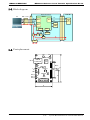
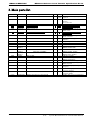
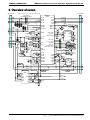
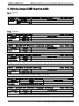
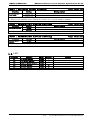
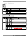
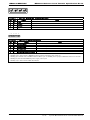
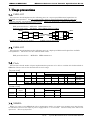
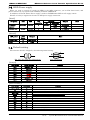
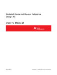
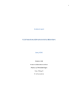
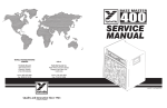
MB86C30-REBFUN-E
MB86C30 Reference board
Function Specification
Rev1.6 September 24, 2009
Fujitsu Microelectronics Limited.
MB86C30-REBFUN-E
MB86C30 Reference board Function Specification Rev1.6
Revised History
Revision
1.0
1.6
DATE
2009/06/03
2009/09/17
Revised content
First created
Reflect “MB86C30 Errata Sheet Rev1.3” , etc
2/13
Fujitsu Microelectronics Limited Confidential
MB86C30-REBFUN-E
MB86C30 Reference board Function Specification Rev1.6
Contents
1 . INTRODUCTION ......................................................................................................................................... 4
2 . OVERVIEW OF BOARD .............................................................................................................................. 4
2 - 1 . FUNCTION ............................................................................................................................................... 4
2 - 2 . BLOCK DIAGRAM ..................................................................................................................................... 5
2 - 3 . PARTS PLACEMENT .................................................................................................................................. 5
3 . MAIN PARTS LIST ...................................................................................................................................... 6
4 . OVERVIEW OF CIRCUIT ........................................................................................................................... 7
5 . SWITCH,JUMPER,LED FUNCTION TABLE ............................................................................................ 8
5 - 1 . SWITCH ................................................................................................................................................... 8
5 - 2 . JUMPER................................................................................................................................................... 8
5 - 3 . LED ........................................................................................................................................................ 9
6 . CONNECTOR PIN ASSIGNMENT ........................................................................................................... 10
7 . USAGE PRECAUTIONS............................................................................................................................ 12
7-1.
7-2.
7-3.
7-4.
7-5.
7-6.
USB3.0-IF ............................................................................................................................................ 12
USB2.0-IF ............................................................................................................................................ 12
CLOCK................................................................................................................................................... 12
NMSEL ................................................................................................................................................ 12
HDD POWER SUPPLY ............................................................................................................................ 13
DEFAULT SETTING ................................................................................................................................. 13
3/13
Fujitsu Microelectronics Limited Confidential
MB86C30-REBFUN-E
MB86C30 Reference board Function Specification Rev1.6
1.Introduction
This document describes a function specification of the reference board for MB86C30 (USB3.0SATA bridge) developed by Fujitsu Microelectronics Ltd.
【Related documentation】
MB86C30 DATA SHEET
MB86C30 User’s Manual
Universal Serial Bus 3.0 Specification
Revision1.0
Fujitsu Microelectronics Limited
Fujitsu Microelectronics Limited
Hewlett-Packard Company,
Intel Corporation,
Microsoft Corporation,
NEC Corporation,
ST-NXP Wireless,
Texas Instruments
2.Overview of board
2-1.Function
MB86C30 Reference board has following functions.
z MB86C30 (USB3.0-SATA bridg chip) embedded.
z One Standard-B receptacle is embedded for USB3.0 interface.
SuperSpeed(5Gbps)/High-Speed(480Mbps)
z One COMBO receptacle is embedded for SATAinterface
SATA Gen2(3Gbps)/Gen1(1.5Gbps)
z SPI-Flash 512Kbit is embedded for external memory.
z The power supply supports two ways of supply methods of USB bus power and the self-power.
(Peripheral Power Connector)
z As for the USB bus power and self-power, achange is possible with a jumper.
4/13
Fujitsu Microelectronics Limited Confidential
MB86C30-REBFUN-E
MB86C30 Reference board Function Specification Rev1.6
2-2.Block diagram
Reference Board
PC
USB3.0 cable
CN
SATA HDD
CN CN
MB86C30
TX
RX
TX
D+/D-
USB3.0
SATA
SATA
RX
HDD
Controller
XTAL
USB2.0
XTAL
VBUS
GPIO
SPI
1.2V 3.3V
SPI-FLASH
JP
DC-DC
LED
CTL
5V
12V
PWRSW
CN
ATX power
2-3.Parts placement
JP5
XTAL
48MHz
SPI
SST25VF512A FLASH
USB-IF
USB-CN
Standard-B
MB86C30
LQFP64
1
JP1
HDD-IF
OSC XTAL
GPIO[6]
GPIO[7]
GPIO[8]
1 CN
PWR
SW
PSW1
6
SATA CONNECTOR
CENTER
MIC2505-1
1
70
GPIO
LED
HDD5V
MB39C022
LED
LED
LED
15
SON10
30
3.3V
5V
7
ATX 4pin
4
3
2
1
43
5/13
Fujitsu Microelectronics Limited Confidential
MB86C30-REBFUN-E
MB86C30 Reference board Function Specification Rev1.6
3.Main parts list
Item
ASSP
Maker
FML
MB86C30
DC-DC
FML
MB39C022G
1
Pow
3.3V
1.2V
5V
FLASH
ESD
SST
MURATA
SST25VF512A-33-4C-SAE
LXES4XBAA6-027
1
1
3.3V
5.0V
ESD
MURATA
LXES15AAA1-017
6
---
FL
MURATA
DLP11TB900UL2 for USB3.0
2
---
PWR-SW
MICREL
MIC2505-1YM
1
5.0V
TI
SN74LVC3G14DCU
1
3.3V
TI
----NIHON
DENPA
NIHON
DENPA
NIHON
DENPA
ROHM
ALPS
SN74LVC1G08DRL
FDV301N
BSS84
2725T 50MHz or 25MHz
1
1
1
1
3.3V
----3.3V
NX5032G STD-CKW-3 (50MHz) or
STD-CSK-4 (25MHz)
NX5032G STD-CSK-4 (48MHz)
1
3.3V
1
3.3V
SML-310MT
SKRPABE010
6
1
-----
Connector
Connector
FOXCONN
FCI
UEB11123-2AK1-4H_327-0000-2014_X1
10034814-001LF
1
1
-----
Connector
MOLEX
15-24-4557
1
---
Connector
MAC8
WL-1-3P
1
---
Connector
MAC8
WL-1-6P
1
---
FOXCONN
USB3.0 Standard-A to Standard-B
--
---
IC
IC
FET
FET
OSC
Crystal
Crystal
LED
Switch
Cable
Type
Num
1
6/13
Note
USB3.0-SATA bridge LQFP64
0.4pitch
DC-DC:600mA/LDO:300mA
SON10
5V->3.3V/1.2V
SPI-FLASH 512kbit SOP8
6line-ESD Protection Array
SOP8 0.65pitch
1-line ESD Protection device
SMD (1005)
USB3.0 common mode choke
1.25x1.0 SMD
1ch/2A switch(Act-High)
SOP8 1.27pitch
Triple Schmitt-trigger inverter
VSSOP8
Single 2-input AND SOT-553
NMOSFET SOT-23
PMOSFET SOT-23
50MHz or 25MHz SMD
MB86C30(SYSCLK)
50MHz or 25MHz SMD
MB86C30(SYS_XI/XO)
48MHz SMD
MB86C30(U2_XI/XO)
LED Green SMD
Push Switch
MB86C30(GPIO[5])
USB3.0 Standard-B right-angle
SATA COMBO right angle socket
SMT 1.27pitch
4pin x 1 ATX peripheral power
5.08pitch
3pin x 1 straight pin header
2.54pitch Jumper
6pin x 1 straight pin header
2.54pitch GPIO
USB3.0 Std-A plug to Std-B plug
Fujitsu Microelectronics Limited Confidential
MB86C30-REBFUN-E
MB86C30 Reference board Function Specification Rev1.6
4.Overview of circuit
※When inplement a part, cut wiring between the PAD
USB3.0 Std-B
CN
SSRX+
SSRXSSTX+
SSTX-
SS_RXP
SS_RXM
0.15uF
SS_TXP
0.15uF
SS_TXM
VBUS
D+
DGND
12kΩ 1%
Not Mounted
D3.3V OSC
STB OUT
25/50MHz
VDD GND
ATX 4pin
CN
25MHz
or XTAL
50MHz NX5032
1
JP1
2
3
FL
R
1kΩ R
R
JP8
1
3 JP7
R
10Ω
0.01uF
FL
FL
FL
FL
CE#
SCK
SO
SI
SCK/GPIO[1]
R
0Ωor220Ω
R
8pFor12pF
SST25VF512A
SCEN_X/GPIO[0]
SYSCLK
FL
FL
10uF
Jumper
10kΩ R
NMSEL/SD/GPIO[2]
JP5
SYS_XO
SYS_XI
SOUT/GPIO[3]
Jumper
LED/GPIO[6]
LED/48SEL/GPIO[7]
LED/IRQ/SYSSEL/GPIO[8]
VBUS
SYSRST_X
SS_VDP
SS_VDN
SS_VDU
U2_AVDB
U2_AVDF1
U2_AVDP
U2_AVDF2
LED
6
ST_VDP
ST_VDN
ST_VDU
VDDE
PLLVDD
VDDI
VSS
R 0Ω
WP#
FL
FL
0Ω
R Not
Mounted
VSS
PSW1
PushSW
DRV R LED
DRV R LED
DRV R LED
Jumper
D3.3V
JP3
4.7kΩ
R
1
2
R
100kΩ
JP4
100kΩ
3 R
PSW/GPIO[5]
U2_XO
U2_XI
D3.3V
VDD
HOLD#
6pin Header
1
FETCTL/SI/GPIO[4]
Jumper
D
S
A+
AB+
B-
0.01uF
0.01uF
0.01uF
0.01uF
Jumper
R 12kΩ
G
U2_HSDP
U2_HSDM
U2_EXT12K
ST_TXP
ST_TXM
ST_RXP
ST_RXM
PTST Open
TMODE[2]
D3.3V
TMODE[1] Open
2
TMODE[0]
D3.3V
33kΩ
0Ω R
48MHz Not Mounted
330Ω
R
XTAL
12pF
G
S JP9
NX5032
D
R
0Ω
10kΩ R R 5.6kΩ
Not Mounted
R 1kΩ
CN
LQFP64
LXES15AAA1-017
Not Mounted
4 +5VDC
3 COM
2 COM
1 +12VDC
SATA COMBO
MB86C30
Not Mounted
DLP11TB900UL2forUSB3.0
Jumper
JP2
Jumper
D3.3V
R
FL
100kΩ
D5.0V
DGND
D12.0V
MIC2505-1YM
SOP8
CTL
FLG
GND GATE
IN
OUT
Jumper
TH
Not
Mounted
5V
JP6
GND
R
MB39C022G
LED
LED
R
12V
SON10
0Ω
R
EN1
EN2
VIN2
GND2
VIN1
GND1
POR
1MΩ R
FL
VOUT2
LX
D3.3V
2.2uH
L
D1.2V
600kΩ R
22pF
FB
200kΩ R
7/13
Fujitsu Microelectronics Limited Confidential
MB86C30-REBFUN-E
MB86C30 Reference board Function Specification Rev1.6
5.Switch,Jumper,LED function table
5-1.Switch
PSW1:MB86C30 setting (GPIO[5])
Function
Reserved
Condition
ON(push-down):L
OFF
:H
Push botton switch
Setting content
Function depends on a deployment program to MB86C30
Normal condition
5-2.Jumper
Jumper (Pin header)
JP1:Power setting
Function
Board power
supply
Setting
SHORT 1-2
SHORT 2-3
Setting content
USB VBUS by a board power supply (USB bus power)
ATX connector input by a board power supply (Self power)
・The DC12V supply to the SATA HDD becomes it only in an ATX power supply.
JP2:HDD-5V Power control setting
Function
HDD-5V power
control
Setting
SHORT
OPEN
Setting content
Control it in GPIO[4] (High:5V-ON Low:5V-OFF)
HDD-5V are always ON
Jumper (Solder pad)
JP3:System clock setting
Function
Select system
clock frequency
Setting
SHORT
OPEN
Jumper (Solder pad)
Setting content
50MHz mode (SYSCLK or SYS_XI/XO)
25MHz mode (SYSCLK or SYS_XI/XO)
・When you use SYSCLK, please short2-3 JP7, and please implement an oscillator in U4.
・When you use SYS_XI/XO, please short1-2 JP7, please remove R9, and please implement crystal in X1.
Jumper (Solder pad)
JP4:USB2.0 clock setting
Function
Select USB2.0
clock
Setting
SHORT 1-2
SHORT 2-3
Setting content
Crystal mode (U2_XI/XO)
Internal clock mode (Generates it than system clock)
・When you use U2_XI/XO, please implement 48MHz crystal in X2.
Jumper
JP5:MB86C30 boot setting
Function
Select MB86C30
boot mode
Setting
OPEN
Short-circuit at power-up (1~2sec)
Setting content
Normal condition
Maintenance mode
JP6:HDD-5V Power supply setting
Function
HDD-5Vsupply
Setting
OPEN
SHORT
Jumper (Solder pad)
Setting content
Normal condition
Please do not set it
・When you let you short-circuit, please remove U3 (MIC2505-1YM).
8/13
Fujitsu Microelectronics Limited Confidential
MB86C30-REBFUN-E
MB86C30 Reference board Function Specification Rev1.6
Jumper (Solder pad)
JP7:System clock setting
Function
Select System
base clock
Setting
SHORT 1-2
SHORT 2-3
Setting content
Crystal mode (X1:SYS_XI/SYS_XO)
Oscillator mode (U4:SYSCLK)
・When you use SYS_XI/SYS_XO, please implement crystal in X1. (NX5032GA 50MHz or 25MHz)
・When you use SYSCLK, please implement oscillator in U4. (2725T 50MHz or 25MHz)
Jumper (Solder pad)
JP8:MB86C30 device setting
Function
Select MB86C30
Setting
OPEN
SHORT
Setting content
Assembly to ES2 and later
Assembly to ES1
Jumper (Solder pad)
JP9:MB86C30 device setting
Function
Select VBUS
control
Setting
OPEN
SHORT
Setting content
Assembly to ES1
Assembly to ES2 and later
5-3.LED
Part name
D1
D2
D3
D4
D5
D6
Function
5V power monitor
3.3V power monitor
HDD-5V power monitor
GPIO[6] monitor
GPIO[7] monitor
GPIO[8] monitor
Color
Green
Green
Green
Green
Green
Green
Polarity
---H
H
H
9/13
Content
Lighting 5V power ON
Lighting 3.3V power ON
Lighting SATA-5V power ON
Fujitsu Microelectronics Limited Confidential
MB86C30-REBFUN-E
MB86C30 Reference board Function Specification Rev1.6
6.Connector pin assignment
56 7 89
2
1
3
4
CN3:USB connector (Standard-B)
Type
USB2.0
No
1
2
3
4
IO
-B
B
--
Signal
VBUS
U2_HSDM
U2_HSDP
DGND
VBUS 5.0V
USB2.0 DUSB2.0 D+
Ground
USB3.0
5
6
7
8
9
O
O
-I
I
SS_TXM
SS_TXP
DGND
SS_RXM
SS_RXP
USB3.0 Super Speed TXUSB3.0 Super Speed TX+
Ground
USB3.0 Super Speed RXUSB3.0 Super Speed RX+
15 14 13 12 11 10 9 8 7 6 5 4 3 2 1
Note
VBUS
DD+
GND
SSTXSSTX+
GND
SSRXSSRX+
7 6 5 4 3 2 1
CN2:SATA connector (COMBO)
Type
Signal
Power
No
1
2
3
4
5
6
7
IO
-O
O
-I
I
--
Signal
DGND
ST_TXP
ST_TXM
DGND
ST_RXM
ST_RXP
DGND
Ground
SATA HTX+
SATA HTXGround
SATA HRXSATA HRX+
Ground
Note
1
2
3
4
5
6
7
8
9
10
11
12
13
14
15
----------------
N.C
N.C
N.C
DGND
DGND
DGND
D5.0V
D5.0V
D5.0V
DGND
N.C
DGND
D12V
D12V
D12V
DC3.3V
DC3.3V
DC3.3V
Ground
Ground
Ground
DC5.0V
DC5.0V
DC5.0V
Ground
Device Activity / Disable Staggered Spin-up
Ground
DC12V When you connected an ATX power supply.
DC12V When you connected an ATX power supply.
DC12V When you connected an ATX power supply.
10/13
2nd
2nd
GND
A+
AGND
BB+
GND
3rd
3rd
2nd
1st
2nd
2nd
2nd
3rd
3rd
2nd
3rd
1st
2nd
3rd
3rd
3.3V
3.3V
3.3V
GND
GND
GND
5V
5V
5V
GND
LED#
GND
12V
12V
12V
2nd
Fujitsu Microelectronics Limited Confidential
MB86C30-REBFUN-E
1
2
3
MB86C30 Reference board Function Specification Rev1.6
4
CN1:ATX power connector
No
1
2
3
4
1
2
IO
-----
3
4
Signal
+12V
DGND
DGND
+5V
5
Note
DC12.0V
Ground
Ground
DC5.0V
6
CN4:GPIO connector
No
1
2
3
4
5
6
IO
*
*
*
*
*
*
Signal
GPIO[3]/SOUT
GPIO[4]/SI/FETCTL
GPIO[5]/PSW
GPIO[6]/LED
GPIO[7]/48SEL/LED
GPIO[8]/SYSSEL/IRQ/LED
Note
33kΩ Internal pull-down
33kΩ Internal pull-down
33kΩ Internal pull-down
33kΩ Internal pull-down
33kΩ Internal pull-down
Connected to CTL of U3(MIC2505-1)
Connected to PSW1(PushSW)
Connected to D4(LED)
Connected to D5(LED)
Connected to D6(LED)
・GPIO[2:0] is used as SPI-FLASH interface.
・GPIO[2,7,8] is shared with a MB86C30 initial setting terminal in the power-up.
・GPIO[3,4] is shared with a UART terminal. (When you use UART, please prepare a RS232 transceiver outside.)
・GPIO[4] is shared with HDD-5V power supply control pin.
・GPIO[6,7,8] is shared with LED. (D4,D5,D6)
11/13
Fujitsu Microelectronics Limited Confidential
MB86C30-REBFUN-E
MB86C30 Reference board Function Specification Rev1.6
7.Usage precautions
7-1.USB3.0-IF
The reference board implements the following parts on a super-speed differential signal line for
EMI/ESD correspondence. But the common mode choke is connected between PAD at a line and
examines whether you implement it individually. When you implement a common mode choke, You cut
wiring between the PAD and implement a part.
ESD protection device:MURATA LXES15AAA1-017
Common mode choke :MURATA DLP11TB900UL2 for USB3.0
T1&T2 pattern (Do not use choke)
T1&T2 pattern (Use choke)
7-2.USB2.0-IF
The reference board implements the following parts on a high-speed differential signal line for ESD
correspondence. But do not use the common mode choke.
ESD protection device :MURATA LXES15AAA1-017
7-3.Clock
The reference board makes all part implementation patterns to be able to confirm all clock methods of
MB86C30. Please refer to list shown below for each usage.
【System clock】
Mode Crystal Oscillator Clock input SYS_XI/XO SYSCLK Frequency JP3 JP7 Parts assembly C25,C26
R36 Y(12pF)
Y(220Ω)
R9 N U4 N Note 50MHz SHORT SHORT 1‐2
X1 Y (50MHz)
25MHz OPEN SHORT 1‐2
Y (25MHz)
Y(8pF) Y(0Ω) N N 50MHz 25MHz SHORT OPEN SHORT 2‐3
SHORT 2‐3
N N N N N N Y Y Y (50MHz) Y (25MHz) NX5032G STD‐CKW‐3 NX5032G STD‐CSK‐4 2725T 2725T 【USB2.0 clock】
Mode
External
Crystal
Internal
Clock
input
U2_XI/XO
----
Frequency
JP4
Parts assembly
X2
R11
48MHz
SHORT 1-2
Y (48MHz)
N
48MHz
SHORT 2-3
N
Y
Note
NX5032G STD-CSK-4
7-4.NMSEL
When you want to start MB86C30 with a maintenance mode, you make it an opening state after having
let JP5 short-circuit at the time of power supply ON for 1 or 2 seconds. Please usually start JP5 as an
open state. JP5 is top layer.(L1)
12/13
Fujitsu Microelectronics Limited Confidential
MB86C30-REBFUN-E
MB86C30 Reference board Function Specification Rev1.6
7-5.HDD Power supply
When you want to control 5V supply for HDD to the SATA connector, you let JP2 short-circuit, and
please control it by a program from a GPIO[4] terminal of MB86C30.
In addition, the board makes JP6 to supply it without U3(MIC2505-1YM) for 5V supply control.
DC12V are always supplied at the time of ATX power supply connection.
【DC5V】
5V power
Program
control
Always ON
JP2
JP6
SHORT
OPEN
U3
assembly
Y
OPEN
OPEN
SHORT
Y
N
GPIO[4]
IO
Condition
Output
High
Low
---------
Output
Note
5V output
Stop
5V output
5V output
【DC12V】
12V power
Always ON
Stop
ATX
Power
Y
N
Output
Note
12V output
Stop
7-6.Default setting
The reference board is shipped by the following initial setting.
1
2
3
JP4, JP7 pattern
JP2, JP3, JP5, JP6, JP8, JP9 pattern
【Jumper】
Part name
JP1
JP2
JP3
JP4
JP5
JP6
JP7
JP8
JP9
Initial setting
SHORT 2-3
SHORT
SHORT
SHORT 1-2
OPEN
OPEN
SHORT 1-2
SHORT
OPEN
Content
Self-power mode (ATX power)
HDD-5V control it in GPIO[4]
System clock is 50MHz mode
USB2.0 clock is external crystal
Normal boot
HDD-5V use the U3 output
System clock is crystal mode
MB86C30 implement ES1
Use VBUS control circuit
【Parts assembly】
Part name
TP1~TP5
C8
C61
D7~D12
T1,T2
R9
R21
R23
R11
U3
U4
X1
X2
Assembly
N
N
N
N
N
N
Y
N
N
Y
N
Y
Y
Content
Test pin
Capacitor for U3(MIC2505-1YM) output delay control
Capacitor for 1.2V power
ESD diode for USB2.0/USB3.0
Common mode choke for USB3.0 SSRX/SSTX
Pull-down resistor for X1
Pull-up resistor for SPI-FLASH WP
Pull-down resistor for SPI-FLASH WP
Pull-down resistor for X2
5V power switch
Oscillator for SYSCLK
Crystal for SYS_XI/XO
Crystal for U2_XI/XO
13/13
Fujitsu Microelectronics Limited Confidential