1
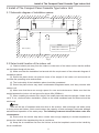
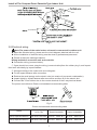
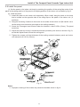
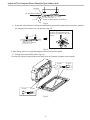
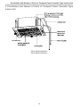
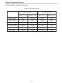
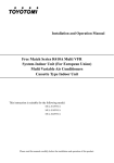
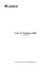
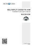
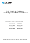
MULTI
DUCTLESS INVERTER
HEAT PUMP
PANEL CASSETTE TYPE
INDOOR UNIT
INSTALLATION MANUAL
Models:
GKH(12)BA-D3DNA2A/I
GKH(18)BA-D3DNA2A/I
User Notice
◆ When operating, the entire capacity of the cooperating indoor unit should be not larger
than 150% of outdoor unit. Otherwise, it will cause the shortage of cooling (heating) capacity.
◆ A Breaker(or fuse) need to be installed in every indoor unit, and the capacity should
in according with indoor unit’s electrical parameter; all the indoor units are required to be
centralized controlled by a total Switch, this Switch can cut off the electric power supply in
case of emergency. The Breaker(or fuse) on each indoor units have the function of short
circuit prevention and abnormal overload avoiding, it should be connected in normal situation.
The total switch controlling the power supply of all the indoor units. Before clearing and
maintenance job being carried out to the indoor units, it is very important to turn off the total
power supply switch.
◆ In order to turn on the units successfully, the main power switch should be opened 8
hours before the operation.
◆ After receiving the turn off signal, every indoor unit will continue to work for 20-70sec to
make use of the rest cool air or the rest heat air in the heat exchanger, while preparing for the
next operation. And this is normal.
◆ When the selected operating mode of the indoor unit are clash with the operating
mode of the outdoor unit, the malfunction light will blink after 5s on the indoor unit or remote
controller showing that the operation clash, then the indoor unit will stop. At this time, change
the operation mode of the indoor unit to the one that would not clash with the outdoor operating
mode to make the operation normal. The cooling mode is not clash with the dry mode, while
the fan mode is not clash with any mode.
◆ The appliance shall not be installed in the laundry.
◆ An all-pole disconnection switch having a contact separation of at least 1/8” (3mm) in all
poles should be connected in fixed wiring.
◆ Information regarding transport/storage temperature -13-131°F (-25-55°C) is missing.
◆ Main switch provided by end user: main switch handle should be black or gray, it can be
locked in “OFF” position with padlock.
◆ The main disconnection device should be explained in user manual and the height
should be recommended at 2-5.8ft (0.6-1.7m) over current protection is required(UL 1995,CSA
C22.2).
◆ The cooling range of the unit is the outdoor environment temp. 23~118°F (-5~48°C)
DB, the heating range of the unit( only for the heat pump type unit) is the outdoor environment
temp. 5~81°F (-15~27°C) WB.
Thank you for your selecting of Cooper&Hunter air conditioner, please read this
usage and install instruction carefully and keep it well in order to use this unit
correctly.
Thank you for choosing a
C&H Multi Ductless Heat Pump!
You can feel confident in your selection because the same
pride incraftsmanship and engineering knowledge that goes
into millions of other C&H installed products worldwide has
gone into your unit.
Please read this owner’s manual carefully before
operationand retain it for future reference.
Contents
1 Safety Information .....................................................................................1
2 Install of The Compact Panel Cassette Type Indoor Unit ..........................2
2.1 Schematic diagram of installation spaces ......................................................... 2
2.2 Select install location of the indoor unit ............................................................. 2
2.3 Important notice ................................................................................................ 3
2.4 Dimension of ceiling opening and location of the hoisting screw (M10)............ 3
2.5 Main body of hoisting air conditioner ................................................................. 3
2.6 Connection of the refrigerant pipe ..................................................................... 4
2.7 Drainage hose ................................................................................................... 5
2.8 Electrical wiring ................................................................................................. 7
2.9 Install the panel ................................................................................................. 8
3 Constitutes and Names of Parts of Compact Panel Cassette Type Indoor Unit .. 10
4 Working Temperature Range . .................................................................. 11
Safety Information
1 Safety Information
Please read this manual carefully before use this unit, and operate it correctly according to the
guide in this manual.
Please take specially note to the meaning of these two marks:
Warning!: This mark means that it may cause casualty or badly heart if the operation is
incorrect.
Note!: This mark means that it may cause casualty or property loss if the operation is
incorrect.
Warning:
◆ Do not adopt fuse with unsuitable capacity or adopt iron thread instead of fuse, otherwise
malfunction or fire may happened.
◆ Cut down the main power switch immediately if malfunction (such as smell the burning odor
etc.) happened.
◆ Maintain ventilation to prevent oxygen leakage in room.
◆ Don’t insert finger or stick like things into discharge vent or outlet grill.
◆ Please make sure that the unit is installed in the place that can bear the weight of it
adequately. If the place is not strong enough, the air conditioner may drop and cause casualty event.
◆ Don’t spray or smear any oil paint or insecticide on the surface of unit, otherwise, fire may be
leaded.
(1). Do not refit the conditioner. Please contact the agency or prefect ional personnel to repair or
move the conditioner.
An all-pole disconnection switch having a contact separation of at least 1/8” (3mm) in all
poles should be connected in fixed wiring.
Note!:
◆ Please check and make sure that the cord, drainage pipe and tubes are connected in the
correct way to prevent leakage of water, refrigerant, electric shock or fire.
◆ The main power must connectable to the earth in order to assure the conditioner earthing
effectively and to prevent electric shock. Please don’t connect the earthing line with the gas pipe,
water pipe, lightening rod or the connecting line of telephone.
◆ The air conditioner should be turned off at least after 5 mins’ operation; otherwise it would
affect the duration of the unit.
◆ Don’t let the children operate the air conditioner.
◆ Please don’t operate the unit by wet hand.
◆ Please turn off the main power of the unit before cleaning the conditioner or change the filter.
◆ Please cut off the main power if the conditioner will be used for a long time.
1
Install of The Compact Panel Cassette Type Indoor Unit
2 Install of The Compact Panel Cassette Type Indoor Unit
2.1 Schematic diagram of installation spaces
Wall
surface
H
>0.75(20)
Wall
surface
Wall
surface
≥59(1500)
≥98 (2500)
≥59(1500)
unit: in (mm)
Model
H
GKH(12)BA-D3DNA2A/I
GKH(18)BA-D3DNA2A/I
10 (260)
Ground
surface
Fig.1
2.2 Select install location of the indoor unit
(1). Obstruct should put away from the intake or outlet vent of the indoor unit so that the airflow
can be blown though all the room.
(2). Make sure that the installation had accord with the requirement of the schematic diagram of
installation spaces.
(3). Select the place where can stand 4 times of the weight of the indoor unit and would not
increase the operating noise and oscillate.
(4). The horizontally of the installation place should be guaranteed.
(5). Select the place where easy drain condensated coagulated water, and easy connect with
outdoor unit.
(6). Make sure that there are enough space for care and maintenance. Make sure that the
weight between the indoor unit and ground is above 98in (2500mm).
(7). When installing the steeve bolt, check if the install place can stand the weight 4 times of the
unit’s. If not, reinforce before installation. (Refer to the install cardboard and find where should be
reinforced)
Note!
There will be lots of lampblack and dust stick on the acentric, heat exchanger and water pump
in dining room and kitchen, which would reduce the capacity of heat exchanger, lead water leakage
and abnormal operation of the water pump. The following treatment should be taken under this
circumstance:
(8). Ensure that the smoke trap above cooker has enough capacity to obviate lampblack to
prevent the indraft of the lampblack by the air conditioner.
(9). Keep the air conditioner far from the kitchen so that the lampblack would not be indraft by
the air conditioner.
2
Install of The Compact Panel Cassette Type Indoor Unit
2.3 Important notice
◆ To guarantee the good performance, the unit must be installed by professional personnel
according with this instruction.
◆ Please contact the local Cooper&Hunter special nominated repair department before installation.
Any malfunction caused by the unit that is installed by the department that is not special nominated
by Cooper&Hunter would not deal with on time by the inconvenience of the business contact.
2.4 Dimension of ceiling opening and location of the hoisting screw (M10)
25in (650mm)
22in (570mm)
25in (650mm)
24in (604mm)
22in (570mm)
16in (400mm)
Fig.2 Install dimension of mode (inches (mm))
GKH(12)BA-D3DNA2A/I,GKH(18)BA-D3DNA2A/I
◆ The drilling of holes in the ceiling must be done by the professional personnel.
6in (160mm)
Installation stands for main body of the unit
Ceiling
Above 0.78in (20mm)
Fig.3
Notes: The dimension for the ceiling openings with * marks can be as large as 24in (610mm).
But the overlapping sections of the ceiling and the decorated surface boards should be
maintained at no less than 0.78in (20mm).
2.5 Main body of hoisting air conditioner
(1). The primary step for install the indoor unit.
◆ When attach the hoisting stand on hoisting screw, do use nut and gasket individually at the
upper and lower of the hoisting stand to fix it. The use of gasket anchor board can prevent gasket
break off.
(2). Use install cardboard.
◆ Please refer to the install cardboard about the dimension of ceiling opening.
◆ The central mark of the ceiling opening is marked on the install cardboard.
3
Install of The Compact Panel Cassette Type Indoor Unit
◆◆Install the install cardboard on the unit by bolt (3 piece), and fix the angle of the drainage pipe
at the outlet vent by bolt.
(3). Adjust the unit to the suitable install place. (Refer to the fig.3)
(4). Check if the unit is horizontal.
◆ Inner drainage pump and bobber switch are included in the indoor unit, check if 4 angle of
every unit are horizontal by water lever. (If the unit is slant toward the opposite of the coagulate
water flow, there may be malfunction of the bobber switch and lead water drop.)
(5). Backout the gasket anchor board used to prevent gasket break off and tighten the nut on it.
(6). Backout the install cardboard.
Fig.4
Note!: Please do tighten the nuts and bolts to prevent air conditioner break off.
2.6 Connection of the refrigerant pipe
◆ When connect the pipe to the unit or backout it from the unit, please do use both spanner and
torque wrench. as shown in fig.5.
◆ When connect, smear both inside and outside of the flare nut with freeze motor oil, screw it
by hand and then tighten it with spanner.
◆ Refer to form 1 to check if the wrench had been tightened (too tight would mangle the nut
and lead leakage).
◆ Examine the connection pipe to see if it had gas leakage, then take the treatment of heat
insulation, as shown in the fig.5.
◆ Only use median sponge to entwine the wiring interface of the gas pipe and heat preservation
sheath of the gas collection tube.
4
Install of The Compact Panel Cassette Type Indoor Unit
Smear freeze motoroil
here
Median sponge (attachment)
(entwine the wiring interface
with seal mat)
Thread fasten(x4)
Torque wrench
Heat preservation
sheath of liquid inlet
tube (attachment) (for
liquid tube)
Spanner
Flare nut
Gas collection tube
Liquid inlet tube
Wiring interface
Heat preservation
sheath of gas collection
tube (attachment)(for
gas tube)
Fig.5
Form 1: The tightening torque needed for tightening nut
Diameter Inch(mm)
Surface thickness(mm)
Tightening torque (N·m)
φ1/4’’ (6mm)
0.02in (0.5mm)
15-30 (N·m)
φ3/8’’ (9mm)
0.03in (0.71mm)
30-40 (N·m)
φ9/12’’ (12mm)
0.04in (1mm)
45-50 (N·m)
φ5/8’’ (16mm)
0.04in (1mm)
60-65 (N·m)
φ3/4’’ (18mm)
0.04in (1mm)
70-75 (N··m)
2.7 Drainage hose
(1). Install the drain hose
◆ The diameter of the drain hose should be equal or bigger than the connection pipes. (The
diameter of polythene pipe: Outer diameter 1”(25mm) Surface thickness 1/16”(1.5mm).
◆ Drain hose should be short and drooping gradient should at less 1/100 to prevent the
formation of air bubble.
◆ If drain hose cannot has enough drooping gradient, drain raising pipe should be added.
◆ To prevent bent of the drain hose, the distance between hoisting stand should is 1m(39in) to
59in(1.5m).
39-59in
Fig.6
◆ Use the drain hose and clamp attached. Insert the drain hose to the drain vent, and then
tighten the clamp.
◆ Entwine the big sponge on the clamp of drain hose to insulate heat.
◆ Heat insulation should be done to indoor drain hose.
5
Install of The Compact Panel Cassette Type Indoor Unit
Sponge(attachment)
Clamp(attachment)
Clamp
Drain hose
Sponge (gray)
Below 0.17in (4mm)
Fig.7
Drain stepup pipe note
◆ The install height of the drain raising pipe should less than 11in (280mm).
◆ The drain raising pipe should form a right angle with the unit, and distance to unit should not
beyond 12in (300mm).
12in (300mm)
39-59in
9in (220mm)
20in (500mm)
11in (280mm)
20in (500mm)
3in (75mm)
Fig.8
Instruction
◆ The slant gradient of the attached drain hose should be within 3in (75mm) so that the drain
hole doesn’t has to endure the unnecessary outside force.
Fig.9
◆ Please install the drain hose according to the following process if several drain hoses join
together.
Fig.10
(2). Check the smoothness of drain after installation.
◆ Check the drain state by immitting 600cc water slowly from the outlet vent or test hole.
◆ Check the drain in the state of refrigerating after installation of the electric circuit.
6
Install of The Compact Panel Cassette Type Indoor Unit
4in (100mm)
4in (100mm)
Fig.11
2.8 Electrical wiring
Note:The power of the entire indoor unit must be connected in outdoor unit.
◆ About the electrical wiring, please see the circuit diagram attached with the unit.
◆ All the installation of electrical wiring must be done by professional personnel.
◆ Please do take the earthing treatment.
Wiring method of connection unit and controller
◆ Connection wiring (communication):
① Open electric box cover, drag the wiring (communication)from the rubber plug A, and impact
them well individually by impact fastener.
② Wiring according to the indoor side circuit diagram.
◆ Fix the impact fastener after connection.
◆ Entwine the small sponge on the electric wire( do entwine it to prevent condensation).
◆ Impact tightly by impact fastener after connection and then fit on the electric box.
◆ Connect the 3 cord rubber wire to the counter terminal of the 3 way terminal board.
The power cord reference Power cord standard recommending table
Fig.12
Power cord standard recommending table
Model
Power Supply
(V, Ph, Hz)
Min. Sectional Area of Min. Sectional Area of
Earth Wire(AWG)
GKH(12)BA-D3DNA2A/I
208~203V-1Ph-60Hz UL1015
GKH(18)BA-D3DNA2A/I
208~203V-1Ph-60Hz
Power Cord(AWG)
AWG 18*1
UL1015
AWG 18*3
UL1015 AWG 18*1
UL1015
AWG 18*3
7
Install of The Compact Panel Cassette Type Indoor Unit
2.9 Install the panel
(1). Set the panel to the indoor unit body by matching the position of the swing flap motor of the
panel to the piping position of the panel to the piping position of the indoor unit as shown by fig.13.
(2). Install the panel
① .Install the panel on the indoor unit temporarily. When install, hang the latch on the hook
that is located on the opposite side of the swing flap on the panel of the indoor unit. (2
positions)
② .Hang the remaining 2 latches to the hooks on the sides of the indoor unit.(Be careful not to
let the swing motor lead wire get caught in the sealing material.)
③ .Screw the 4 hexagon head screws under the latches in about 0.59in (15mm). The panel
would rise.
④ .Adjust the panel by turning it toward the direction pointed by the arrow as shown in fig.13,
so that the adjust board connect the ceiling well.
⑤ .Tighten the screws until the thickness of the sealing material between panel and indoor
unit reduced to 0.2-0.3in (5-8mm).
Fig.13
Notes:
① .Improper screwing of the screws may cause the troubles shown in fig.14.
8
Install of The Compact Panel Cassette Type Indoor Unit
Air leak
Air leak from ceiling
Water condensatation, water drop
Fig.14
② .If gap still exist between ceiling and decoration panel after tightening the screws, readjust
the height of the indoor unit. (As shown in fig.15)
If the raising lever and drain hose are
not affect, can adjust the height of
indoor unit by the hole on the corner
of panel.
Gaps are not allowed
Fig.15
※ After fixing, be sure no gap left between the ceiling and the panel.
③ .Wiring of the decoration panel (Fig.16)
Connect the joints for swing flap motor lead wire (at 2 places) installed on the panel.
At body
At body
At pane
Fig.16
9
At pane
Constitutes and Names of Parts of Compact Panel Cassette Type Indoor Unit
3 Constitutes and Names of Parts of Compact Panel Cassette Type
Indoor Unit
GKH(12)BA-D3DNA2A/I
GKH(18)BA-D3DNA2A/I
10
Working Temperature Range
4 Working Temperature Range
Working Temperature Range
Indoor side state
Outdoor side stae
Dry bulb
temp. °F (°C)
Wet bulb
temp. °F (°C)
Dry bulb
temp. °F (°C)
Wet bulb
temp. °F (°C)
Rated Cooling
81(27)
66(19)
95(35)
75(24)
Max. cooling
90(32)
73(23)
118(48)
79(26)
Min. cooling
70(21)
59(15)
64(18)
-
Rated Heating
68(20)
59(15)
45(7)
43(6)
Max. heating
27(81)
75(24)
64(18)
Min. heating
68(20)
5(-15)
3.2(-16)
59(15)
11
www.cooperandhunter.us
MANUFACTURER: GREE ELECTRIC APPLIANCES, INC. OF ZHUHAI
Add: West Jinji Rd, Qianshan, Zhuhai, Guangdong, China, 519070