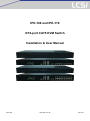
1
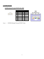
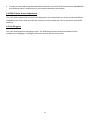
IPK-108 and IPK-116 8/16-port CAT5 KVM Switch Installation & User Manual IPK-108 www.lcsi.com.tw IPK-116 Copyright This document contains proprietary information that is protected by copyright. All rights reserved. No part of this document may be photocopied, reproduced, or translated into another language without express prior written consent of the originator. The software described in this manual is furnished under a license agreement and may be used only in accordance with the terms of that agreement. Disclaimer Information in this document is subject to change without notice and does not represent a commitment on the part of the originator. We provide this document “as is,” without warranty of any kind, expressed or implied, including, but not limited to, its particular purpose. We reserve the right to make improvements and/or changes to this manual, or to the products and/or the programs described in this manual, at any time. Information provided in this manual is intended to be accurate and reliable. However, we assume no responsibility for its use, or for any infringements on the rights of third parties that may result from its use. This product might include unintentional technical or typographical errors. Changes are periodically made to the information herein to correct such errors, and these changes are incorporated into new editions of the publication. 2 Contents CONTENTS .................................................................................................................................................................. 3 CHAPTER 1 INTRODUCTION ..................................................................................................................................... 5 1.1 PACKAGE CONTENTS......................................................................................................................................... 5 1.2 FRONT PANEL VIEW........................................................................................................................................... 7 .3 REAR PANEL VIEW .............................................................................................................................................. 7 1.4 W ORKABLE UNITS ............................................................................................................................................. 8 1.5 FEATURES ........................................................................................................................................................ 8 1.6 SYSTEM REQUIREMENTS ................................................................................................................................... 9 1.7 TECHNICAL SPECIFICATIONS ............................................................................................................................ 10 1.8 CABLES DIAGRAMS ......................................................................................................................................... 11 CAT5/5E/6 Straight Through UTP/STP Cable: 8P8C .................................................................................. 11 CHAPTER 2 HARDWARE INSTALLATION ..............................................................................................................12 2.1 INSTALL KVM DONGLE FOR CONTROLLED PC .................................................................................................. 12 2.2 SINGLE CAT5 KVM INSTALLATION – ACCESS UP TO 8 / 16 PCS ......................................................................... 12 2.3 DDC-2 PROTOCOL SUPPORT .......................................................................................................................... 12 2.4 DDC/CI AUTO SCREEN ADJUSTMENT .............................................................................................................. 13 2.5 HOT PLUGGING ............................................................................................................................................... 13 CHAPTER 3 OPERATION .........................................................................................................................................14 3.1 PORT SELECTION SWITCHES BY OSD MENU .................................................................................................... 14 3.2.1 Selecting a Computer .........................................................................................................................14 3.2.2 OSD Hot-Key Functions .....................................................................................................................15 F1: Auto (Auto Scan) ...................................................................................................................................15 F2: Name (Port Name) ................................................................................................................................15 F3: Secu (Security) ......................................................................................................................................16 F5: Manu (Manual Scan) .............................................................................................................................16 F6: (Check Mark) .....................................................................................................................................16 F7: ACPI * (Green command) .....................................................................................................................17 CTRL: More (More function setup) ..............................................................................................................25 CHAPTER 4 KVM OVER IP MODULE (OPTIONAL) ................................................................................................29 4.1 KVM OVER IP MODULE INSTALLATION .............................................................................................................. 29 4.2 REMOTE WAKEUP ........................................................................................................................................... 29 CHAPTER 5 CAT5 KVM EXTENDER MODULE (OPTIONAL) .................................................................................32 5.1 CAT5 EXTENSION CONSOLE UNIT INSTALLATION .............................................................................................. 32 5.2 CONSOLE CONTROL SWAP .............................................................................................................................. 32 5.3 VGA RESOLUTIONS ........................................................................................................................................ 32 CHAPTER 6 TROUBLESHOOTING ..........................................................................................................................33 6.1 THE COMPUTER BOOT UP FINE, BUT KEYBOARD AND/OR MOUSE DOESN‟T WORK. ................................................. 33 6.2 CAT5 CONSOLE EXTENDER POWER LED IS NOT ON. ....................................................................................... 33 6.3 NO VIDEO SIGNAL IS DISPLAYED ON THE REMOTE MONITOR. ............................................................................... 33 3 6.4 VIDEO SIGNAL IS FOGGY OR UN-CLEARED ON THE SCREEN. ................................................................................ 33 4 Chapter 1 Introduction 1.1 Package Contents Set Items 8/16 port CAT5 KVM Switch Standard Suite Installation and User Manual CD-ROM With 1 Built-in CAT5 Extender Transceiver Rack Mount Kit (up to 300m) 150m/300m CAT5 Extension Console Unit Optional KVM over IP Module CAT5 PS2 or Receiver (CAT5 Extension Console Unit for (installed on Module port) USB Dongle Built-in CAT5 Extender) Please make sure all of the components are present and in good order. If anything is missing, or was damaged in shipping, please contact your local dealer. Please read this manual thoroughly and follow the installation and operation procedures carefully to prevent any damage to the switch or to any other devices. Easy Management The unit is an 8/16 ports CAT5 KVM console switch that allows both local and extend operators to monitor and access multiple servers from a single console (Keyboard, Mouse and Monitor). They are designed with the intelligent video Gain/EQ (equalizer) adjustments to tweak the video image individually for each server so that each server can be 40 meters away from the unit. Extend Control Distance The console extender is designed to control the KVM Switch up to 1000 feet away from your keyboard, Mouse and VGA monitor. The Internal Up-Link port is to synthesize the signals of PS/2 keyboard, PS2 mouse and VGA monitor for being easily transmit to a CAT5 Dongle at remote over popular Ethernet Cat5 cable. The CAT5 Extension Console Unit gets the synthetic signal and return it back to the signal of PS2 keyboard, PS2 mouse and VGA monitor respectively. Cat5 STP cable (shielded Twisted Pair) / UTP cable (Unshielded Twisted Pair) or enhanced cable like Cat5e/Cat6 cable is applied to LAN network popularly. The Cat5 KVM designed with the RGB skew adjustment for 1000 feet application and support real time access server. Besides, CAT5 KVM Extender is utilized with popular CAT5 cable or existed CAT5 cable layout systems in the building but it is not apply LAN protocol to CAT5 cable. There is more reliable security on CAT5 KVM Extender to avoid hacker intruding the PCs. Access PC from Anywhere This Switch offers a slot for connecting IP Remote Console module: The KVM over IP Module. It redirects local keyboard, mouse and VGA monitor data to a remote administration console and allows you to control one or many computers locally at the server site or remotely via the Internet using a standard browser. You can securely gain BIOS level access to systems for maintenance, support, or failure recovery over the Internet. Communication is secure via SSL authentication and encryption. Use in conjunction with a KVM switch for multiple-server access. The KVM over IP Module provides a non-intrusive solution for remote access and control. Remote access and 5 control software runs on its embedded processors only but not on mission-critical servers, so that there is no interference with server operation or impact on network performance. Save Energy, Save Money The KVM switch for saving the connected PCs power and method thereof, by choosing the green command which set up on the OSD (On Screen Display) Menu of this PC switch --- SLEEPING, WAKE UP and POWER OFF to be sent to the target PC , go through PS2 keyboard port or USB port between the target PC . Once the target PC receives the green command from PS2 keyboard port or USB port, it would go to POWER OFF mode, SLEEPING mode, WAKE UP mode, against what green command (POWER OFF or SLEEPING or WAKE UP) the target PC received from the PC switch. This action will reduce the target PC idle power, avoid PC equipment wearing like Hard disk, PC fan, Power supply, …etc. and achieve energy saving and carbon reduction and Centralized control. Reduce cable bulk With server densities continually increasing, cable bulk remains a major concern for network administrators. The Cat5 KVM switches significantly reduce KVM cable volume in the rack by utilizing the innovative Cat5 Dongle and single, industry-standard Unshielded Twisted Pair (UTP) cabling. This allows a higher server density while providing greater airflow and cooling capacity. The Cat5 Dongle is powered directly from the target device and provides keep-alive functionality when the switch is not powered. The Cat5 Dongle is a data communication device that provides the primary interface between a serial device and a KVM switch. 6 1.2 Front Panel View Description No. Component ON-Line LED POWER LED ON-Line LED is light in “Green” means the console port is linked to this PC port Power LED is light in “Red” on means PC is power on .3 Rear Panel View No. Component KVM ports x 8 1 Description Links to KVM Cat5 Dongle (KVM ports x 16 have 16 RJ-45 ports ) 2 Mouse port x 1 A local console PS/2 Mouse plugs in here. 3 Keyboard port x 1 A local console PS/2 Keyboard plugs in here. 4 CAT5 Extension port x 1 Links to Extension Console Unit 5 USB port x 2 A local console USB Keyboard & Mouse plugs in here. 6 VGA port x 1 A local console VGA monitor plugs in here. Upgrade port x 1 Links to a PC USB port (USB Type A) for firmware upgrading 7 (USB Type B) 8 Power Socket Outlet x 1 The power Adapter Cord plugs in here. 9 Module Port x 1 Install KVM over IP module (Optional) here. 7 1.4 Workable Units The IPK-108/116 works with the following units. Model No. Description USBD USB Type KVM Dongle for controlled PC PS2D PS/2 Type KVM Dongle for controlled PC C5E-150/300 CAT5 Extension Console Unit for Built-in CAT5 Extender (150m/300m) KVM over IP module Over IP console card 1.5 Features 1-Console 8/16-port CAT5 KVM switch Support combo interface for connecting to PC ports conveniently Support full CAT5 interface on all PC ports for reducing KVM cable bulk Support the connections include one local console(mouse, keyboard and VGA), one built-in CAT5 extender and one slot for optional plug-in IP remote console module Support Microsoft Windows, Netware, Unix, Linux Support iMAC, Power MAC and Sun Micro Systems (SUN Micro system to PS2 Keyboard mapping table) with USB port No Software Required - easy PC selection via On Screen Display (OSD) Menu Hot Plug – add or remove connected PCs without powering off the KVM switch or PCs Support up to 1600 x 1200 video resolution for 500 feet CAT5-Based remote console, 1600 x 1200 video resolution for 1000 feet CAT5-Based remote console 1600 x 1200 video resolution for IP-Based remote console Keyboard status restored when switching PCs support password security Each server can be 40 meters away from this KVM Switch by CAT5 UTP cable. Supports DDC-2 protocol and DDC/CI auto screen adjustment Supports both USB and PS/2 Cat5 dongle connected to PC or Server. Supports both USB and PS/2 local keyboard/mouse. Supports local console, CAT5 extension console (Optional) and IP Remote console (Optional) access. An optional CAT5 extension Console unit can be linked for an extension operator (up to 1000 feet away from the Cat5 KVM). Simple On-Screen Display (OSD) makes servers easy to access and control. firmware upgradeable Rack mount kit for 19” RACK 8 1.6 System Requirements 1 x VGA Monitor Local Console 1 x USB or PS/2 Keyboard 1 x USB or PS/2 Mouse 1. 1 x CAT5 cable 2. 1 x CAT5 KVM Extension Console Unit (optional): Built-in CAT5 KVM extender 1 x VGA Monitor 1 x USB or PS/2 Keyboard 1 x USB or PS/2 Mouse 1 x CAT5 LAN cable KVM over IP module(optional) 1 x Mini USB cable 1 x Null modem cable (for reset to factory default) 9 1.7 Technical Specifications Model 8 ports 16 ports KVM Type CAT5 KVM PC Port Connector RJ-45, 8P8C PC Ports 8 Max. Distance (KVM switch to PC ) 40m Video Resolution (Local Console) 1600 x 1200 DDC2B Video Resolution (Remote Console) 1600 x 1200 for CAT5-Based 500 feet remote console 1024 x 768 for CAT5-Based 1000 feet remote console 1600 x 1200 for IP-Based remote console Console Ports Local console: 1 x HDDB 15 pin female 1 x mini DIN 6 pin female(for mouse) 1 x mini DIN 6 pin female(for keyboard) 2 x USB A-type receptacle 16 Remote console CAT5 extender(Extension Console Unit optional) 1 x RJ-45 Connector CAT5 Dongle(ps/2) One end: 1 x HDDB 15 pin female 2 x PS2 mini DIN 6 pin female The other end 1 x RJ-45 Connector CAT5 Dongle(USB) One end: 1 x HDDB 15 pin female 1 x USB A-type plug The other end: 1 x RJ-45 Connector Firmware upgrade port 1 x RJ-45 Connector PC selection On Screen Display (OSD) Menu, Hot Key PC Port LEDs 2LEDs: - Power (Red), - Online (Green) Auto-Scan Intervals 3, 8, 15, 30 Sec Keyboard/Mouse Emulation PS/2, USB Housing Metal, 19” Rack mount, 1U Power AC100V-240V, 60Hz Operation Temperature 0 ~ 50℃ Storage Temperature -20 ~ 60℃ Humidity 0~95%, Non-Condensing Dimension 440 mm×185 mm×42 mm 10 1.8 Cables Diagrams CAT5/5E/6 Straight Through UTP/STP Cable: 8P8C Figure .1 Pin Wire Color Pair 1 White Orange 2 Function T 2 Orange 2 R 3 White Green 3 T 4 Blue 1 R 5 White Blue 1 T 6 Green 3 R 7 White Brown 4 T 8 Brown 4 R CAT5/5E/6 Straight Through UTP/STP Cable 11 Chapter 2 Hardware Installation Make sure that power to all the devices you will be connecting up have been turned off. You must unplug the power cords of any computers that have the Keyboard Power On function. 2.1 Install KVM Dongle for Controlled PC Plug your USB and/or PS/2 type KVM Dongle Unit into Controlled PC. 2.2 Single CAT5 KVM Installation – access up to 8 / 16 PCs The Single unit of CAT5 KVM installation can access up to 8 / 16 computers. To install the CAT5 KVM, please follow the next steps: 1. Connect the local Monitor, keyboard and mouse to the appropriate CAT5 KVM console ports. 2. Connect a CAT5e/6 cable between CAT5 KVM port and the KVM Dongle. 3. Install an Extension Console Unit (Optional):Connect a CAT5e/6 cable between Extension Console Unit and CAT5 KVM [LINK] port. For image EQ, Gain and RGB Skew adjustment, please refer to the Installation manual. For the DDC-2/EDID protocol to function properly, please Power ON all equipments in sequence of: Power ON the CAT5 KVM local Monitor. Power ON all controlled computers. Power ON CAT5 KVM 2.3 DDC-2 Protocol Support The CAT5 KVMKVM Switch supports the DDC-2/EDID protocol; this enables all connected computers with DDC-2 capable graphics cards read BE-608 local monitor‟s EDID information, and automatically set compatible resolutions and refresh rates. The CAT5 KVM handles DDC-2 as follows: 1. As the CAT5 KVM powers on, it checks for a local monitor. If a local monitor is connected and ON, the CAT5 KVM sends the DDC-2/EDID information of the local monitor to all connected KVM Dongles. On the first time installation or when the local monitor changed, we suggest you reboot the CAT5 KVM to get correct EDID information from the local monitor. 12 2. To make sure the KVM Dongle with latest EDID information, the CAT5 KVM will resends the DDC2B/EDID to KVM Dongle when it switches focus to the computer attached to that Dongle. 2.4 DDC/CI Auto Screen Adjustment The CAT5 KVM supports DDC/CI screen auto adjustment. It is recommended to use the monitor with DDC/CI compatibility both for the local and extension consoles in order to adjust the video to the screen center while switching. 2.5 Hot Plugging The CAT5 KVM supports hot plugging function. The KVM Dongle can be removed and added into the installation by unplugging or re-plugging without the need to shut the device down. 13 Chapter 3 Operation The CAT5 KVM provides 3 different interfaces (1) Touch Panel (2) OSD menu (3) IR Remote Control that offer quick and convenient computer access and control. 3.1 Port Selection Switches by OSD Menu The CAT5 KVM provides OSD (On Screen Display) interface. The OSD menu can be activated by using Hot-keys. To Active the OSD, press the <Ctrl> key twice within two seconds , you may see the OSD Main Menu screen showing a list of the computers with corresponding KVM port ID numbers, names and status, see the following picture. (The default OSD active-key is <Ctrl>, you may change to <Shift> or <Alt>, see Chapter 3.3 Define Hot-key) Currently selected Real Time Clock shows current time channel ID No. Channel ID (Port No.) Time scheduling Power Management Highlighted by Arrow keys Instructions and Hot-Keys The CH and Name displayed in yellow means that Computer is powered ON and can be accessed. The CH and Name displayed in white means that Computer is powered OFF. 3.2.1 Selecting a Computer 1. The currently selected Channel ID is displayed on up-right corner. 2. Navigate to the desired computer with the arrow keys, and press <Enter>. The selected computer‟s screen appears on the monitor, with a confirmation label like that shown below, which identifies the computer accessed. Use the console keyboard and mouse to control the selected computer. PC ports selection confirmation label 14 3.2.2 OSD Hot-Key Functions F1: Auto (Auto Scan) In this mode, the console automatically switches from one powered-on computer to the next sequentially in fixed interval time. During this [Auto Scan] mode, the OSD will display the name of computer scanned. During this mode, you may press <Space> or <Enter> key anytime to access the scanned computer. Press <Esc> to abort the [Auto Scan] mode, and into OSD Main Menu. You may press <↑> or<↓> key to enter a [Manual Scan] mode. You will see the following screen. In [Manual Scan] mode, you may scan powered-on computers one by one by keyboard control. Press <↑> to previous computer and the <↓> to select the next computer. Press <←>, <→> to move OSD displayed position. To abort [Manual Scan] mode, press <ESC>. F2: Name (Port Name) To help remember which computer or Slave CAT5 KVM is attached to a particular port, every KVM port of CAT5 KVM can be given a name. To edit name of a computer, press <F2>, up to 8 / 16 characters. Valid characters are „A‟~‟Z‟, „0‟~‟9‟ and „-„. Lowercase are converted to uppercase ones. Once the port name is given, it will be saved in KVM Dongle. If you change the KVM Dongle, however, the old port name for that port will be 15 kept unless you manually modify/delete it or attach another KVM Dongle to that port. F3: Secu (Security) This function protects individual computers from unauthorized KVM access; by default it is disabled. To enable, high-light the computer you want to protect then press <F3>. A “!” mark shows that the Security function is enabled. To access a “!” locked computer, highlight it and press <ENTER>; the admin password challenge appears. After entering the correct password, you are allowed to control the selected computer. The computer is automatically re-locked once you switch to another computer. To disable the password-protected function, just select the computer and press <F3> again, enter the correct password. Note: The Password-protected computers (“!” marked) are skipped during [Auto Scan] and [Manual Scan] mode. F5: Manu (Manual Scan) Press <F5> to enter [Manual Scan] mode. A label similar to the following appears: In this mode, you can scan powered-on computers one by one by keyboard control. Press the <↑> to select the previous computer and the <↓> arrow to select the next computer. Press the <←>, <→> to change the position of the scanned computer information box. To abort [Manual Scan] mode, press <ESC>. F6: (Check Mark) This is a scan filter. In order to limit [Auto Scan] or [Manual Scan] to certain computers, give those computers a checked mark “”. To set, highlight the computer, and press <F6> to toggle the mark on or off. Use “Scan Type” to set up scanning so it includes just those computers you checked. 16 CAT5 KVM supports two Scan modes: [Auto Scan] and [Manual Scan]. And there are two Scan Type options for Scan mode: [Ready PC]: will scan all powered-on computers, except those with the Security “!” setting. [ Ready PC + ]: will scan only powered-on computers that have a check mark “”assigned, except those with the Security “!” setting. To cancel the check mark “”, press <F6> again. F7: ACPI * (Green command) Before start using ACPI commands in the KVM, user should confirm the settings in BIOS work with ACPI commands. The following are introductions of setting BIOS to support ACPI commands; we‟ll follow Phoenix BIOS‟s settings for example, which is one of the global leading brands in BIOS Company. NOTICE: Before start using ACPI features, please make sure your motherboard installed latest firmware and support ACPI features. *Note: ACPI (Advanced Configuration and Power Interface) ACPI (Advanced Configuration and Power Interface), a power management specification developed by Intel, Toshiba and Microsoft that makes hardware status information available to the operating system. ACPI combines the earlier Advanced Power Management (APM) and PnP BIOS into an enhanced power management system. ACPI support is built into Windows starting with Windows 98; however, the PC's chipset and BIOS must also support it. It provides a platform-independent, industry-standard approach to operating-system-based power management. The ACPI specification is the key constituent in OSPM (Operating System Directed Power Management). OSPM and ACPI apply to all classes of computers, including handheld, notebook, desktop, and server machines. The ACPI OS takes over the power-management and Plug and Play functions from the legacy BIOS interfaces and allows inexpensive power-management hardware to support elaborate power-state transitions, maximizing the computer's power consumption and resource-utilization efficiencies. State Product Support Description 17 S0(Working) System appears off. The CPU is stopped; RAM is refreshed; the system is running in a low power mode. S1 (sleep) & System appears off. The CPU is stopped (Sleep) or has no Use built–in CAT5 KVM’s OSD S3 (standby) power (Standby); RAM is refreshed (sleep) or slow refresh ACPI functions to enter the S1 (standby); the power supply is in a reduced power mode. mode S4 System appears off. The hardware is completely off, but Use IP Module (Optional) installed (Hibernate) system memory has been saved as a temporary file onto on CAT5 KVM to wake up your the hard-drive. computer from S4 mode (Wake On LAN) S5(Off) System is off. The hardware is completely off, the operating Use built–in CAT5 KVM’s OSD system has shut down; nothing has been saved. Requires ACPI functions to enter the S5 a complete reboot to return to the Working state. mode(Turn off computer) The picture above shows the screen computer boots, notice the「Press DEL to enter SETUP」hint on the lower left corner? Press the <Delete> to enter the BIOS setup menu. NOTICE! Boot screen may vary depending on the host computer models of different brands vary, but probably will be prompted the hotkey to enter the BIOS setup menu at the beginning of the boot phase. Enter BIOS setup menu hint mostly last for only 3-5 seconds, so better to press the hot key immediately at the beginning of boot phase to make sure enter the BIOS setup menu properly, and don‟t need to waste time for reboot. 18 After entered the BIOS setup menu, the screen is as follows: Use<↓>, <↑> key which locate near the numpad to move the bar to the「Power Management Setup」item, and then press Enter key to open the setup page. Move bar to「ACPI Suspend Type」item, we can see system default is [S1],which we don‟t need to change now. 19 NOTICE: IF the default value of「ACPI Suspend Type」item isn‟t [S1], please follow the steps to change the setting: 1. Press <Enter> to open the item value choosing window. 2. Please move the square to S1(POS), then press <Enter> to change the value and back to the「Power Management Setup」 setup page. 3. You confirm the value of「ACPI Suspend Type」item has already changed to [S1(POS)] at the「Power Management Setup」 setup page. Press <F10> to save the changes, the confirmation window will pop out as shown above, enter “Y” and then press <Enter> to confirm the change and reboot the system. 4. The way of set the value of「ACPI Suspend Type」item at [S3(STR)] is similar to set up [S1(POS)] process. It will cause the computer unable to been wake up by ACPI commands but can only been wake up by press the power switch. 20 After the completion of BIOS settings, then describes how to use the ACPI Commands to manage the computer and save energy usage. When enter the Windows after the system reboot, double-click <Ctrl> to open the OSD menu of CAT5 KVM. Picture above shows the hot keys and Instructions at the lower field of OSD menu, where you can find 「F7: ACPI」. Move the bar to the chosen port number you want in the Channel ID list, and press <F7> to open the ACPI command list. 21 After pressing the F7 function key, the ACPI command list will appear under the Channel ID list, shows「►ACPI: POWER」 「►ACPI: Sleep」 「►ACPI: Wakeup」, which has 3 ACPI commands to choice as follows: 1. Power:Press <Enter> will send a shout down command to chosen port. 2. Sleep:Press <Enter> will send a suspend command to chosen port. 3. Wakeup:Press <Enter> will send a Wake up command to chosen port. Only works on a computer at suspend mode. Press <↑>, <↓> key to switch the ACPI command to be sent. To send the SLEEP command, please see the picture: 22 Press <Enter> and computer will go to the suspend mode. Any PC go to the suspend mode, the channel ID and other labels will be shown on green color, just like the picture shows. After enter the suspend mode, the screen will go black except the OSD menu. You can wake up a computer from the suspend mode by using Wakeup ACPI command or by using the WOL (Wake On LAN) feature of KVM over IP module (optional). For KVM over IP module, please see Chapter 4. For ACPI command, please follow process below: Choose a PC in sleep mode Press <F7> to open the ACPI command list, then choose wakeup at ACPI command list as shown above, then press <Enter>. 23 The picture above shows the computer screen after wake up. If wants to shout down the computer, double-click <Ctrl> to open the OSD menu then press <F7>. Choose Power at ACPI command list as picture shown. 24 After pressing <Enter>, computer will shut down. In addition to manage your computers through CAT5 KVM’s OSD ACPI functions to save energy, you can even inform your computers when to sleep and/or wake up by arrange their power schedule through a built-in RTC (Real Time Clock) features. Please see the power schedule settings in the following pages. CTRL: More (More function setup) By pressing <CTRL> from the OSD Main Menu, you can access more functions of OSD. The Setup Menu appears as below and it‟s include Adjust Video, Scan Type, Scan Rate, CH Display, OSD Hotkey, OSD Timer, OSD Position, Switch Hotkey, Admin Password, Rest Mode Timer, Enter Rest Timer functions. Most functions have options to choose from. Use the<↑>, <↓> to select the desired function then press <Enter>. Available options are shown, one at a time, at the bottom of the Setup Menu. Again use <↑>, <↓>to select an option, then press <Enter> to activate it. To abort Setup Menu, just press <Esc>. 25 Adjust Video You can tune the image quality for each individual remote screen displayed on the Console monitor. To adjust a screen image: 1. Switch to the computer whose image you want to adjust. 2. Double-click <Ctrl> to start the OSD Main Menu. 3. Press <Ctrl> to open the extended Setup (MORE) Menu. 4. Highlight Adjust Video, and press <Enter>. 5. The Adjust Video dialog appears: 6. Use the <↑>, <↓>to select options for video adjustment. 7. Adjust the image by pressing <←>, <→>, <PgUp> or <PgDn>. The value is from 0 to 255(Brightness, Phase) or 0 to 31(R, G, B) 8. When the image meets your requirements, press <ESC> to accept and quit. The setting is retained in the individual KVM Dongle Unit. Scan Type To setup a Scan Type for [Auto Scan] / [Manual Scan] mode. There are two options: [Ready PC]: will scan all powered-on computers, except those with the Security “!” setting. [Ready PC + ]: will scan only powered-on computers that have a check mark “”assigned, except those with the Security “!” setting. 26 Scan Rate This sets the display duration for each computer displayed in Scan mode. Default settings are: 3 seconds, 8 seconds, 15 seconds, and 30 seconds. CH-Display (Channel ID/Name Display) There are two options: Always On: The label with the Channel (i.e., port ID) number and name of the selected computer and/or OSD status will be displayed on the screen all the time. Auto Off: The label with the Channel ID and name of the selected computer and/or OSD status will be displayed on the screen for 3 seconds, then automatically disappear. Define Hot-key (Define Hot-key for OSD Menu) The default hotkey to activate the OSD menu is <CTRL>. Select any of the three hotkey options: <CTRL>, <SHIFT>, or <ALT>. Operation remains the same, e.g., if you select <SHIFT>, then press<SHIFT>twice activates the OSD, but you still press <CTRL> to go from the OSD Main Menu to the Setup Menu. OSD Timer (OSD Timeout) There are four options for the automatic timeout period of the OSD screen: 30, 45, 60 or 80 seconds. This represents the amount of time the OSD remains showing. When it times out, the OSD turns off. Double press your designated hotkey (default: <CTRL><CTRL>) if you want it to appear again. OSD Position (OSD Display Position) To set up the position of selected computer name and/or OSD status displayed on screen during operation. Use the <↑>, <↓> to select Up Left, Up Right, Middle, Low Left, and Low Right. The actual display position depends somewhat on VGA resolution. Switch Hotkey The value of default hotkey to switch port is OFF. Select any of the three hotkey options: <CTRL>, <SHIFT>, or <ALT> to enable the switch hotkey function. Operation is to press the hotkey twice then enter the port no. For example, if you select <SHIFT> for your switch hotkey and want to switch to port 1, press<SHIFT>twice and Enter “1”. Admin Password Once the Admin Password protection is set, you can only access the OSD menu by supplying the assigned password. Don‟t forget it. The Admin Password is also used to access computers protected with the Security “!” setting. (See F3: Security.) To change a new password, please enter the OLD password and set a new one. In the event of a password lost, you need to reset this unit back to default password. (To know how to reset CAT5 KVM to default, please contact your dealer) Rest Mode Timer This sets the timeout timer, the amount of time the system remains in active KVM mode if undisturbed (no keyboard or mouse activity). If undisturbed for more than the set amount of time, the CAT5 KVM goes to sleep, and the monitor goes black. The options are: 0 Minutes, 1 minute, 5 minutes, and 10 minutes.0 means never sleep. 27 To awaken the system from Rest Mode, hit any key. Enter Rest Mode (Force to Rest mode) This is a security feature that allows you to force immediate rest mode. Select Enter Rest Mode, press <Enter.> The system goes immediately into rest mode; the screen goes blank. To awaken the system from Rest Mode, hit any key. Note: Once Admin Password is set, a password-asking box will be displayed first, please enter the assigned password to awaken the system from Rest Mode. Set Time (Setup Time in OSD menu) Press <Enter> to open the time setup field, then press <Backspace> to erase the time and enter digits to setup the time. After setup is finished, press <Enter> to apply the change. CAT5 KVM use 24-hour time system. 28 Chapter 4 KVM over IP Module (Optional) The CAT5 KVM supports a KVM over IP Module. To install it, you can manage your CAT5 KVM connected computers from anywhere in the world. For more details, please refer to the KVM over IP Guide. To add KVM over IP Module here 4.1 KVM over IP Module Installation Turn off the CAT5 KVM first, and then slide the KVM over IP Module into Module Port on CAT5 KVM gently. Make sure the KVM over IP Module is installed on CAT5 KVM firmly, then secured it on CAT5 KVM with screw. 4.2 Remote Wakeup The IP-KVM provides the remote power wakeup function, which can remotely wake up the sleeping computer. With this feature, the computers that are not in use for now can be shut down and remotely wake up the computer when want to use it, and thus save the power energy. Figure 0-1 Remote Wakeup Settings on target computer: In order to be waked up, some settings have to be done on the target computer: 1. BIOS setting: Have the wake up function in BIOS Enabled Note: the naming in BIOS varies depending on the BIOS type; it may be Wake On LAN/PME, PME Event Wake Up, or Power On By PCI Device. 2. Windows Settings: Enter the Properties of Local Area Connection. 29 Make sure Wake on Magic packet is Enabled. Make sure the following two items are selected. 30 Settings on IP-KVM: The control can be easily set up from the web page. 1. Click on Remote Control > Remote Wakeup to bring up the configuration page. 2. Click on More entries to add additional controlled target 3. Key in the server description and the server‟s IP address 4. Click on Get MAC to get the corresponding MAC address of the server 5. Click on Apply to save the entry 6. Click on Reset to defaults if want to clear all entries 31 Chapter 5 CAT5 KVM Extender Module (Optional) CAT5 KVM Extender Module is a CAT5 Extension Console Unit module. The CAT5 KVM Extender Module is a due functions device it is a CAT5 KVM receiver that uses CAT5 cable to extend your keyboard, mouse and monitor 1000 feet, it also has built-in 2 to1 OSD KVM switch used the same peripheral for your local PC. The CAT5 KVM Extender Module is not only an extender for high-density applications where you want full use of keyboards, mouse, and monitor but there isn‟t room for a server nearby, but also can doubles your productivity, allow you to operate and control remote system while working on local PC at your desk. 5.1 CAT5 Extension Console Unit Installation 1. 2. 3. 4. 5. 6. Make sure the CAT5 cable is straight through type. Plug CAT5 cable one end into RJ-45 connector of KVM switch‟s CAT5 console and the other end of CAT5 cable into KVM CAT5 Extension Console Unit RJ-45 port. Connect remote keyboard, mouse and monitor to R-Box (CAT5 Extension Console Unit) USB Keyboard/Mouse port and Monitor port. Connect Local PC to R-box (CAT5 Extension Console Unit) by using accompanied HDDB-15 to PS/2/USB/VGA Power on the CAT5 Extension Console Unit by plug in the power adaptor Select remote console by push button 5.2 Console Control Swap This 1+1 console is designed as one control double view, both local console and remote console can access and view the server but only one at a time, Local console and Remote console of KVM Switch will have the same priority to control computer. The change of the control as follow ; after 2 seconds no keyboard and mouse input any console can take over the control and switch the KVM or operate on server another console can view the same display. 5.3 VGA Resolutions CAT5 Extension Console Unit can send keyboard, mouse and video signals up to remote KVM switch with auto adjustable video equalization and video signal boost features for the best possible video quality. The R-Box professional version can extend your PC console up to 300m away at VGA resolution 1024x768. CAT5 cables has CAT5, CAT5e, CAT6 and STP/UTP types; If your application need high VGA resolution and long distance please select high end cables. It is highly recommended to use “optimal CAT5 cable length “to get the best video quality and don‟t waste unnecessary CAT5 cable. 32 Chapter 6 Troubleshooting 6.1 The computer boot up fine, but keyboard and/or mouse doesn’t work. Make sure the keyboard/mouse works when directly plugged into the computer first. If not, try a different keyboard/mouse instead, use 101, 102 or 104-key keyboard only. PS/2 keyboard and mouse ports are not designed for hot plug. USB mouse and keyboard ports can hot plug, but need to wait few second for PC bus emulations. Don‟t press any keys on the keyboard or moving the mouse or pressing the mouse buttons when switching ports while the selected computer is booting up. Otherwise, it might cause the keyboard/mouse error or keyboard is not detected at PC side. 6.2 CAT5 Console Extender power LED is not ON. Make sure power adapter is connected to KVM CAT5 extender. 6.3 No video signal is displayed on the remote monitor. Please check the situations below: VGA cables & connectors and CAT5 cables & connectors are loosed or disconnected. VGA cable was not attached to computer during boot up process. Power adapter is not connected to extender. 6.4 Video signal is foggy or un-cleared on the screen. Please check VGA connector, or the VGA resolution is too high for the length of cable being used. If the problem happened at VGA resolution, try shortening the CAT5 cable length or reducing VGA resolution. It is highly recommended to use “optimal CAT5 cable length “to get the best video quality and don‟t waste unnecessary CAT5 cable. Video resolutions supported up to 1024 X 768 for CAT5-Based 1000 feet remote user and up to 1600 X 1200 for CAT5-Based 1000 feet remote user. Check the local monitor ground if the CAT5 Extension Console Unit do not have a local PC. The KVM switch will provide DDC information to all the PC VGA board, if the local both console‟s monitor and KVM switch have been turn on before the PC boot up, if the PC boot up faster then the KVM the PC miss the DDC (Data Display Channel) information so please turn off the PC and wait for a few minutes then turn on again. 33