1
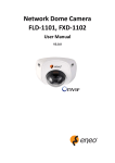
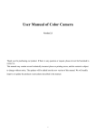
NETWORK CAMERA User Manual V2.0.0 2009-8 Thank you for purchasing our product. If there are any questions, or requests, please do not hesitate to contact the dealer. This manual applies to DS-2CD862MF-E, DS-2CD852MF-E, DS-2CD762MF-FB(H), DS-2CD752MF-FB(H), DS-2CD752MF(-E), DS-2CD852F series Network Camera This manual may contain several technical incorrect places or printing errors, and the content is subject to change without notice. The updates will be added to the new version of this manual. We will readily improve or update the products or procedures described in the manual. DISCLAIMER STATEMENT “Underwriters Laboratories Inc. (“UL”) has not tested the performance or reliability of the security or signaling aspects of this product. UL has only tested for fire, shock or casualty hazards as outlined in UL’s Standard(s) for Safety, UL60950-1. UL Certification does not cover the performance or reliability of the security or signaling aspects of this product. UL MAKES NO REPRESENTATIONS, WARRANTIES OR CERTIFICATIONS WHATSOEVER REGARDING THE PERFORMANCE OR RELIABILITY OF ANY SECURITY OR SIGNALING RELATED FUNCTIONS OF THIS PRODUCT.” 1 User Manual of Network Camera Safety Instruction These instructions are intended to ensure that the user can use the product correctly to avoid danger or property loss. The precaution measure is divided into ‘Warnings’ and ‘Cautions’: Warnings: Serious injury or death may be caused if any of these warnings are neglected. Cautions: Injury or equipment damage may be caused if any of these cautions are neglected. Warnings Follow these safeguards to Cautions Follow these precautions to prevent serious injury or death. prevent potential injury or material damage. Warnings 1. In the use of the product, you must strictly comply with the electrical safety regulations of the nation and region. 2. Source with AC 24V or DC 12V according to the IEC60950-1 standard. Please refer to technical specifications for more details. 3. Do not connect several devices to one power adapter as an adapter overload may cause over-heating and can be a fire hazard. 4. Please make sure that the plug is firmly inserted into the power socket. 5. When the product is installed on a wall or ceiling, the device should be firmly fixed. 6. If smoke, odor, or noise rise from the device, turn off the power at once and unplug the power cable, then contact the service center. 7. If the product does not work properly, please contact your dealer or the nearest service center. Never attempt to disassemble the camera yourself. (We shall not assume any responsibility for problems caused by unauthorized repair or maintenance.) 1 2 User Manual of Network Camera Notice: 1. Make sure the power supply voltage is correct before using the camera. 2. Do not drop the camera or subject it to physical shock. 3. Do not touch CCD (Charge Coupled Device) modules with fingers. If cleaning is necessary, use a clean cloth with a bit of ethanol and wipe it gently. If the camera will not be used for an extended period of time, put on the lens cap to protect the CCD from dirt. 4. Do not aim the camera at the sun or extra bright places. A blooming or smear may occur otherwise (which is not a malfunction however), and affecting the endurance of CCD at the same time. 5. The CCD may be burned out by a laser beam, so when any laser equipment is being used, make sure that the surface of the CCD will not be exposed to the laser beam. 6. Do not place the camera in extremely hot or cold temperatures (the operating temperature should be between -10°C ~ +60°C), dusty or damp locations, and do not expose it to high electromagnetic radiation. 7. To avoid heat accumulation, good ventilation is required for a proper operating environment. 8. Keep the camera away from liquids. 9. While shipping, the camera should be packed in its original packing, or packing of the same texture. 10. Regular part replacement: a few parts (e.g. electrolytic capacitor) of the equipment should be replaced regularly according to their average life time. The average time varies because of differences between operating environment and usage history, so regular checking is recommended for all users. Please contact with your dealer for more details. 2 3 User Manual of Network Camera Index Chapter 1 Introduction ................................................................................................................................................. 1 1.1 Network camera Functions and Features ....................................................................................................... 1 1.2 Applications ................................................................................................................................................... 2 Chapter 2 Installation................................................................................................................................................... 3 2.1 Panels Description ......................................................................................................................................... 3 2.1.1 Side Elevation of the Camera ............................................................................................................. 3 2.1.2 Rear Panel Description ....................................................................................................................... 5 2.2 Product Installation ........................................................................................................................................ 8 2.2.1 Box camera Installation ...................................................................................................................... 8 2.2.2 Dome camera Installation ................................................................................................................... 9 2.2.3 Vandal proof Dome camera Installation............................................................................................ 10 2.2.4 Topological graph of network camera .............................................................................................. 12 2.3 Client Software Installation ......................................................................................................................... 13 Chapter 3 Parameter Configuration ........................................................................................................................... 16 3.1 Visit Network Camera in LAN .................................................................................................................... 16 3.2 Configuration via Web browser ................................................................................................................... 17 3.3 Configuration via Client Software ............................................................................................................... 20 3.4 Visit Network Camera in Internet ................................................................................................................ 26 3.4.1 Visit network camera with static IP .................................................................................................. 26 3.4.2 Visit network camera with dynamic IP ............................................................................................. 27 Chapter 4 Menu Introduction..................................................................................................................................... 31 4.1 Main Menu .................................................................................................................................................. 31 4.2 Menu Introduction of 2.0 Megapixels CMOS Network Camera ................................................................. 32 4.2.1 Language settings ............................................................................................................................. 32 4.2.2 Flicker Control .................................................................................................................................. 32 4.2.3 Resolution settings ............................................................................................................................ 32 4.2.4 Frame settings ................................................................................................................................... 33 4.2.5 Shutter settings.................................................................................................................................. 33 4.2.6 Auto Gain settings............................................................................................................................. 34 4.2.7 DAY / NIGHT Settings ..................................................................................................................... 34 4.2.8 White Balance Settings ..................................................................................................................... 35 4.2.9 Effect Mode settings ......................................................................................................................... 35 4.2.10 Mirror mode settings ....................................................................................................................... 36 4.2.11 ePTZ settings .................................................................................................................................. 37 4.3 Menu Introduction of 1.3Megapiixels CCD Network Camera .................................................................... 37 4.3.1 Language settings ............................................................................................................................. 38 4.3.2 Resolution settings ............................................................................................................................ 38 4.3.3 Frame settings ................................................................................................................................... 38 4.3.4 Lens settings ..................................................................................................................................... 38 4.3.5 Shutter ............................................................................................................................................... 39 4.3.6 Auto Gain settings............................................................................................................................. 39 4.3.7 DAY / NIGHT Settings ..................................................................................................................... 39 3 4 User Manual of Network Camera 4.3.8 White Balance Settings ..................................................................................................................... 40 4.3.9 BACKLIGHT COMPENSATION.................................................................................................... 41 4.3.10 Mirror mode settings ....................................................................................................................... 42 Appendix 1 SADP Introduction ................................................................................................................................. 44 Appendix 2 Port Map ................................................................................................................................................ 46 Appendix 3 Pin Definition ......................................................................................................................................... 48 Appendix 4 Product Specification ............................................................................................................................. 49 DS-2CD862MF-E .............................................................................................................................................. 49 Specification .............................................................................................................................................. 49 Dimension .................................................................................................................................................. 50 DS-2CD852MF-E .............................................................................................................................................. 51 Specification .............................................................................................................................................. 51 Dimension .................................................................................................................................................. 52 DS-2CD762MF-FB ........................................................................................................................................... 53 Specification .............................................................................................................................................. 53 Dimension .................................................................................................................................................. 55 DS-2CD752MF-FB ........................................................................................................................................... 56 Specification .............................................................................................................................................. 56 Dimension .................................................................................................................................................. 58 DS-2CD752MF-E .............................................................................................................................................. 59 Specification .............................................................................................................................................. 59 Dimension .................................................................................................................................................. 60 DS-2CD852F ..................................................................................................................................................... 61 Specification .............................................................................................................................................. 61 Dimension .................................................................................................................................................. 62 4 1 User Manual of Network Camera Chapter 1 Introduction Network camera is a kind of embedded digital surveillance product that combines the features of both traditional analog camera and net DVS (Digital Video Server). Due to the embedded Linux operation system and the latest Davinci hardware platform of TI, the system operates with high scheduling efficiency. Furthermore, the firmware is burned in the flash, which makes the product small, reliable and highly stable. 1.1 Network camera Functions and Features Functions: Network Function :support the TCP/IP protocols(TCP/IP,HTTP,DHCP,DNS,RTSP RTCP,PPPoE, Furthermore,FTP,SMTP,NTP,SNMP addible),and IE browsing. Heartbeat Function: The server can acquire real time operating performance of the network camera through the heartbeat function. Alarm Function: The product includes 1 channel of alarm signal input and 1 channel of alarm on/off output, and supports motion detection, video missing, mask alarm and external alarm input.(Get details in Specification) Voice Talking:Support bidirectional voice talking and monomial voice broadcasting. User Management: Support multilevel right management. The administrator can create up to 15 separate users with different right levels, which highly improves the system security. Compression Functions: Support resolution of 4CIF (PAL:704 × 576, NTSC:704 × 480), DCIF (PAL:528 × 384, NTSC:528 × 320), 2CIF (PAL:704 × 288, NTSC:704 × 240), CIF (PAL:352 × 288, NTSC:352 × 240),QCIF (PAL:176 × 144, NTSC:176 × 120). Support resolution up to 1600×1200 Pixels for 2.0 megapixels Network Camera. Support resolution up to 1280×960 Pixels for 1.3 megapixels Network Camera. Remote Control: The product offers a 10M/100M self-adaptive Ethernet interface. Support TCP / IP, HTTP, DNS, RTP / RTCP, PPPoE protocols. Set the parameters, browse real time videos or check the camera performance through software or IE, and get external alarming and store the compressed bit rate through network. Support remote upgrades and maintenance. RS-485 supports monomial transparent channel function so that clients on remote PC can control the serial devices. Support NAS storage. 1 2 User Manual of Network Camera 1.2 Applications This camera is ideal for remote control network applications. E.g.: 1. Network surveillance for ATM, bank counters, supermarkets and factories. 2. Remote surveillance for nursing homes, kindergartens and schools. 3. AI janitors. 4. AI building/district management systems. 5. Self-service systems of power plants. 6. Outdoor monitoring systems for bridges, tunnels and crossroad traffic. 7. Pipelining and warehouse monitoring. 8. 24-hour monitoring for road traffic. 9. Remote monitoring of forest and water resources. 10. Surveillance for airdrome, railway station, bus stop etc. 2 3 User Manual of Network Camera Chapter 2 Installation Notes: 1. 2. 3. 4. 5. Please check if all the items on the package list have been included with your camera. Read the following contents carefully before the installation. Make sure that all the related equipment is power-off during the installation. Check the power supply to prevent any damage caused by mismatching problems. If the product does not operate properly, please contact your dealer or the nearest service center. Never attempt to disassemble the camera yourself. Users are responsible for any problem caused by modification or repairing without authorization. 2.1 Panels Description 2.1.1 Side Elevation of the Camera Fig 2.1.1 Side Elevation of DS-2CD852MF-E and DS-2CD852F network camera Fig 2.1.2 Side Elevation of DS-2CD862MF-E network camera 3 4 User Manual of Network Camera Fig 2.1.3 Side Elevation of DS-2CD752MF-E network camera Fig 2.1.4 Side Elevation of DS-2CD752MF-FB DS-2CD762MF-FB network camera 4 5 User Manual of Network Camera 2.1.2 Rear Panel Description Fig. 2.1.4 Rear Panel of DS-2CD852F series 1. Standard Ethernet (UTP) RJ45 (10M/100M self-adaptive). 2. 1 channel voice talk input,3.5mm audio interface, 2.0~2.4Vp-p, 1kΩ. 3. 1 channel voice talk output, 3.5mm audio interface, electric line level, 600Ω. 4. 1 channel alarm output (1A 1B). 1 channel alarm input signal (IN,G). RS-485 bus interface (T+ T-). 5. SD card slot (Support SDHC ). 6. Power supply interface of 12VDC, ±10%. Fig. 2.1.6 Rear Panel of DS-2CD852MF-E, DS-2CD862MF-E network camera 1. Standard Ethernet (UTP) RJ45 (10M/100M self-adaptive). 5 6 User Manual of Network Camera 2. 1 channel voice talk input,3.5mm audio interface, 2.0~2.4Vp-p, 1kΩ. 3. 1 channel voice talk output, 3.5mm audio interface, electric line level, 600Ω. 4. SDHC card slot (Support SDHC ). 5. 1 channel alarm input signal. 6. 1 channel alarm output (1A 1B). Please refer to Section 2.3.2 for pin definition. (The external series-wound power should be under 12V DC/ 30mA). 7. RS-485 bus interface (T+ T-). 8. Standard BNC for 1 channel video output. 9. GND. 10. Power supply indicate lamp. 11. Power supply interface of AC24V or DC12V. Fig. 2.1.7 Rear Panel of DS-2CD752MF-E series Address& protocols dial switch, define for dial switch: , from 1 to 5 dial switch function as follows: Switch 1 2 3 4 5 Function ON OFF SHARP AES BLC FL NAGC SOFT AI OFF ON SAGC 6 7 User Manual of Network Camera Notices: There are invalid dial switches for DS-2CD702, DS-2CD712, DS-2CD792, DS-2CD732 series from 6 to 10; 1. SD card slot:Supports SDHC card, and the dimensions of SD meet the market’s normal standard. 2. Fixed Screw: Loosen this screw to rotate the camera horizontally and vertically to adjust the pan and tilt position. When the camera angle is determined, lock the fixed screw to fix the camera. 3. Video cable slot: The analog output is not as high definition as network output. The analog video output is just for testing when something unexpected happens. 4. Ethernet Interface: The Ethernet interface is a RJ45 10M / 100M self-adapted Ethernet port. And the three indicate LED’s respectively mean transmission and receipt status, link status and power status. 5. Cable Hole: User can select a cable hole from the side or bottom of the camera to thread the cables. When selecting one direction to thread the cable, please cover the other 7 8 User Manual of Network Camera cable hole with a waterproof plug. 6. Lens: First, loosen the zoom lock handle, rotate it until there is an appropriate view angle between TELE and WIDE, then tighten the handle. Loosen the focus lock handle, rotate it until getting a clear image between NEAR and FAR, then tighten the handle. 2.2 Product Installation 2.2.1 Box camera Installation Box camera can be fixed in both metope and ceiling. Customers can choose whichever way according to their specific needs. Please follow the steps below:(Take fixing in ceiling as an example, fixing in metope follows the same rule).Choose the fixing method and fix the camera bracket accordingly. If it is metope, then you need to fix the expand bolt (note: the mounting hole of the expand bolt should align with the bracket) before fixing the bracket. If the wall surface is wooden, the first step can be ignored and you can use the self-tapping screw to directly fix the bracket. Please note that the metope on which the camera is fixed should be able to bear at least three times the weight of the bracket and the camera. 8 9 User Manual of Network Camera Fig 2.2.1 Fix Ceiling Bracket Fig 2.2.2 Fix Camera Fig 2.2.3 Fix Lens 2.2.2 Dome camera Installation Dome camera can be installed include hold equipment, ceiling mounted, cylinders and other styles. Client can be installed in accordance with their own ways to achieve the installation.Please according the following specific steps to install (take ceiling mounted as example), when the wall is wood, use the self-tapping screws to fix the ceiling plate to the wall surface. 9 10 User Manual of Network Camera Fig 2.2.4 Fix card Fig 2.2.5 Fix in Ceiling Take the three columns of Dome camera insert in the three fix slot of the ceiling plate. Pay attention to the direction of insertion. Let the ceiling plate “I” logo and the Dome camera “I” logo in the same direction. Meanwhile, make the Dome camera along the counterclockwise Rotate 15 degrees until the switch to the fixed date. At the same time, the “I” signs on the Dome camera and the locking screw on the ceiling plate is alignment. Then screw down the locking screw on the Ceiling plate. Fig 2.2.6 Dome camera fixing Fig 2.2.7 Dome camera fixed 2.2.3 Vandal proof Dome camera Installation The ceiling mount is a suitable installation method for this camera. Please stick to the following steps: 1. First, loosen the screw with a hexagonal Screw driver (attached with the camera), and take down the 10 11 User Manual of Network Camera transparent cover shown as below: Fig. 2.2.8 Unload the Cover 2. Use the screws to fix the dome camera on the ceiling. Fig. 2.2.9 Install the Camera 3. Adjust the camera’s view angle while watching the video on the adjustment monitor. Loosen the fixed screws, and adjust horizontally and vertically the camera pan and tilt. Adjust the lens focus to get optimal video effect. 4. Tighten the screw after adjusting camera’s view angle, and cover the transparent casing. 11 12 User Manual of Network Camera Fig. 2.2.10 Install the Cover 2.2.4 Topological graph of network camera Megapixels Network Box Camera Application: Megapixels Network Dome Camera Application: 12 13 User Manual of Network Camera Notice: Fig 2.1.12 Alarm output The alarm output is an on/off output that requires external power supply on connection. The external power supply shall be 12V DC/30mA, or use AC with external relays. Equipment damage or electric shock may cause if without relays. 2.3 Client Software Installation Note: It is recommended that user’s computer adopted INTEL P3, P4, C4, Core4 CPU, and well-known brands (Asus, Gigabyte, MSI, ECS, and INTEL etc.)Intel chipset motherboard, to ensure the stability of the system. Tested the following models of the current graphics cards support the software installed,ATIRadeonX1650,X1600,X1550,X1300,X800,X600,X550,HD2400,HD2600,NVIDIA GeForce 8600GT,8500GT,8400GS,7600,7300LE,6600LE,6200LE,INTEL915/945G, pay attention to graphics driver must support hardware scaling function. Step1: Double click ‘Client software 4000 (v2.0)’ in the Windows Operating System. The ‘Preparing Setup’ dialog box will pop up automatically; 13 14 User Manual of Network Camera Fig.2.3.1 Client Software Installation Step2: Input “User Name”, “Company Name”; Fig.2.3.2 Customer Information Step3: Select the destination folder and click ‘Next’ to go to the next step. 14 15 User Manual of Network Camera Fig2.3.3 Ready to Install the Program Step4: Click ‘Install’ to start installation till finish the installation; Fig2.3.4 Installation Complete Click the ‘Finish’ button to close the dialog box. After the client software has been installed, you can find the remote client software through “Start” -> “Programs” on your PC. 15 16 User Manual of Network Camera Chapter 3 Parameter Configuration There are several network parameters of the camera which need to be set after the hardware installation. Those parameters including IP address, subnet mask and port number, etc. can be set through various kinds of methods, 2 of which are introduced as below. 1. Set the camera parameters via IE. 2. Set the camera parameters through the client software. Please make sure that the PC and network camera are connected and can ping successfully before the parameter setting. 3.1 Visit Network Camera in LAN There are two ways of connecting between IPC and PC as below: Fig. 3.1.3 Cross Line Connection Fig. 3.1.1 Direct Line Connection Before visiting network camera, user should detect its IP address. SADP is a tool software which can automatically detect hikvision’s network device in the LAN and give the device’s information like IP address, mask, port number, device serial number, software version and so on. 16 17 User Manual of Network Camera Fig. 3.1.2 Select the device, and set its IP address and mask at the same network segment with the PC. The detailed introduction of SADP, please refer to Appendix 1. 3.2 Configuration via Web browser Before visit the camera via web browser, user should adjust security level. Open the web browser, and enter the menu “Tool/ internet option/Security/Custom level”, then set the security level to Security Level –Low, or enable ActiveX Control and the Plug-in directly. Figure 3.2.1 gives you a visual illustration. After you can see the camera video, recover the security level for security. 17 18 User Manual of Network Camera Fig. 3.2.1 Set the Security Level The default IP of the camera is 192.0.0.64 with 8000 as the default port, admin as the administrator, 18 19 User Manual of Network Camera and 12345 as the password. The administrator can create up to 15 separate operators with different right levels. To login the camera through IE, input the IP address in the address column, and the “Login” dialog box will pop-up as Fig. 3.2.2. Input your user name and password, and then click “Login” to enter the “preview” page. Double click the “Camera 01” channel or “Preview” button to preview the video as Figure 3.2.3. Right click the “Camera 01” channel, and the “Main Stream”, “Sub Stream” and “Open sound” options will popup. Select the Open sound option if you connect a pickup to the camera. Fig. 3.2.2 Login Interface Fig 3.2.3 Preview Interface The “Playback” and “Log” functions can be used only in the condition of existing SD card. To set the camera parameters through IE browser, click “Config” and wait for the “Remote Parameters Config” 19 20 User Manual of Network Camera dialog box to pop up, and then set the parameters like IP address, etc. for your demand as Fig. 3.2.4. Enter the menu by invoking the 95th preset. Select the function you want by clicking the direction key. Click the IRIS+ button you can enter the submenu. The menu operation is like the remote control. Note: If plug the SD card into the camera, user should enter the “config” and select “other function” to format the SD card. For more specific information of “Remote Parameters Config”, please refer to “Instructions of Client Software (version 4.01)” from Section 2.5.3 of remote-distance parameter settings. Instructions can be found in the client software4.01 in the path of “Start” → “Program”→ “client software 4.01” after installation. Fig. 3.2.4 Remote Parameters Configuration 3.3 Configuration via Client Software After the installation of client software-4000(v2.0), there is a short-cut icon named “Client Software-4000(v2.0)” on computer’s desktop. Please double click client software icon, a message box of “Register Administrator” as Fig. 3-4-1 will appear the first time running. Password should be more than 6 digits for registration. Note: Please keep the user name and password in mind .You will not be able to get access the software without the proper login information. 20 21 User Manual of Network Camera Fig.3.4.1 Register Administrator Enter the registered user name and password as Fig. 3.3.2. Click “Login” to enter the “Preview” menu as Fig. 3.3.3. Fig. 3.4.2 User Login Fig. 3.4.3 Preview Menu Click the “Configure” button in Fig. 3.3.4, and then right click the blank white space. Click the “Add Area” button, and the “Add Area” message will pop up. 21 22 User Manual of Network Camera Fig. 3.4.4 Add Area Fig. 3.4.5 Add Area Properties Input the area name (you can create whatever name you like) and click “OK” as Fig. 3.3.6. Then right click the area you have just created as Fig. 3.3.7. 22 23 User Manual of Network Camera Fig. 3.4.6 Area Name Adding Completed Fig. 3.4.7 Right Click the Area Name Click “Add Device”, and the “Add Device” dialog box will pop up as Fig. 3.3.8. Input your “Device Name”. Select “Normal” from “Register” option. Input your camera IP in “Device IP”, e.g. 192.0.0.64; “User Name”: admin, “Password”: 12345, and 8000 for the default “Port”, and then modify “Channel” to 1. Click the “OK” button as Fig. 3.3.8. 23 24 User Manual of Network Camera Fig. 3.4.8 Add Device Fig.3.4.9 Camera Adding Completed Click the “Preview” button to enter the “Preview” menu as Fig. 3-3-10. Double click the channel name in the left tree to preview the camera feed. 24 25 User Manual of Network Camera Double click the channel Fig.3.4.10 Preview Menu Please refer to “Client Software-4000(v2.0)_ENG.pdf” for a more detailed parameters configuration. You can find the document in the PC Operating System after the installation of client software 4000 v. 2.0 by selecting “Start”-> “All Programs”-> “client software 4000 v. 2.0”. Fig.3.4.11 Remote Configuration 25 26 User Manual of Network Camera 3.4 Visit Network Camera in Internet 3.4.1 Visit network camera with static IP When there is a static IP from an ISP, open some ports (such as 80 and 8000 ports) in the router. Then a user can visit it through a web browser or client software via the internet. The steps for port forwarding are different for each model of router. Please call the router manufacturer for assistance with port forwarding or visit www.portforward.com. Note: Refer to Appendix 2 to for a detailed explanation about Port Map. Users can directly connect the network camera to the internet without using a router. Fig.3.5.1 Static IP through Router access IPC Fig.3.5.2 Static IP access IPC directly For the client software to view the camera, in the adding equipment column, select the normal model, and fill in the IP info. 26 27 User Manual of Network Camera Fig.3.5.3 Selecting Normal Mode 3.4.2 Visit network camera with dynamic IP Fig.3.5.4 Visit camera through PPPoE dail-up This camera supports the PPPoE auto dial-up function, connecting the camera to a Modem for dial-up access to an ADSL network to get a public IP address; First, through local network access to the network camera, select “Configure””Right Click the Device”, Select “Remote Configuration”, Select “PPPoE Settings” under “Network Paramters” fill in the PPPoE user name and password and confirm the password. Please restart the network camera after completion of configuration. Then the network camera can obtain a dynamic IP from an ISP operation business. However, the obtained IP address is dynamically assigned via PPPoE, so the IP address always changes accompanied with modem rebooting. 27 28 User Manual of Network Camera Fig.3.5.5 PPPoE configuration dialog box It is inconvenient to view a network camera with a dynamic IP, therefore, users should register with a dynamic DNS service provider. (Such as DynDns.com) Domain name resolution contains normal domain name resolution and private domain name resolution. First, we will introduce normal domain name resolution. 1. Normal Domain Name Resolution Fig.3.5.6 Normal Domain Name Resolution Apply a domain name from a domain name provider, then view the camera via the applied domain name. If the camera connects to the internet via a router, users should port forward the router. Please refer to Appendix 2. 28 29 User Manual of Network Camera Input domain names in the client software or IE to view the network cameras. Take the client software configuration as an example. Fig.3.5.7 Selecting Normal Domain Mode 2. Private Domain Name Resolution Fig.3.5.8 Private Domain Name Resolution A PC with a static IP which is running the domain name resolution service is necessary. When the network camera connects to the internet through PPPoE and obtains an IP address, it will send its name and IP address to the resolution server. When the client software connects to the network camera, it will connect to the resolution server and tell the resolution server the expected 29 30 User Manual of Network Camera camera’s name. And the server will find the camera from all the registered cameras and send its IP address to the client software. Once the client software gets the IP address, it can connect the network camera. Fig.3.5.9 Selecting Private Domain Mode 30 31 User Manual of Network Camera Chapter 4 Menu Introduction Note: In this chapter, we call DS-2CD852MF-E, DS-2CD752MF-FB, DS-2CD752MF(-E), DS-2CD852F, as 2.0 megapixels CMOS network camera. And call DS-2CD862MF-E, DS-2CD762MF-FB as 1.3 megapixels CCD network camera. 4.1 Main Menu Call preset 95 and the menu will appear on the screen.”IRIS +” means “enter”, while “IRIS -” means “cancel”. Press up / down to move the cursor, and press left / right to select the item. Note: Take 2.0 megapixels CMOS network camera for example. Fig.4.1.1 Call 95th Preset 31 32 User Manual of Network Camera The main menu displays as below: Fig.4.1.2 Main Menu 4.2 Menu Introduction of 2.0 Megapixels CMOS Network Camera 4.2.1 Language settings Press left / right to select language between Chinese and English; 4.2.2 Flicker Control Press left / right to select frequency between 50HZ and 60HZ in the FLICKER CONTROL item; 4.2.3 Resolution settings RESOLUTION can’t be changed by pressing left / right button; User can select resolution through “configuration””remote configuration” “channel configuration ”“Resolution”; 32 33 User Manual of Network Camera 4.2.4 Frame settings FRAME can’t be changed by pressing left / right button; User can select resolution through “configuration””remote configuration” “channel configuration ”“Frame rate”; The relationship between frame and resolution is as below table: Model Resolution Max. Frame Rate Max bitrate (recommended) NTSC DS-2CD852MF-E DS-2CD752MF(-E) DS-2CD752MF-FB UXGA 10 4M HD720p 15 3M SVGA 30 2.5M 4CIF 30 1.5~2M VGA 30 1.5M Dcif 30 1.5M 2cif 30 1.5M Cif 30 384K~768K Qcif 30 384K~512K Note: DS-2CD852F’s frame and resolution relationship is different from above table. Please refer to the specifications in the Appendix. 4.2.5 Shutter settings SHUTTER can be adjusted by pressing left / right. And there are three options in this item: OFF, auto × 2 and auto × 5; “OFF” means the regulation of the shutter exposure time is default; “Auto × 2” means the regulation of shutter the exposure time is considerably wider; “Auto × 5” means the regulation of the shutter exposure time is at its maximum. The corresponding frame and resolution at different SHUTTER modes is as below: 60Hz Resolution OFF Auto × 2 Auto × 5 QCIF CIF 2CIF DCIF 4CIF VGA SVGA 30fps 15fps 5fps 33 34 User Manual of Network Camera HD720p 15fps 15fps 5fps UXGA 10fps 10fps 5fps 4.2.6 Auto Gain settings Press left / right to adjust AUTO GAIN level among OFF, low, middle and high; 4.2.7 DAY / NIGHT Settings Press left / right to select DAY / NIGHT mode among DAY, NIGHT and AUTO; Fig.4.2.1 DAY Mode 34 35 User Manual of Network Camera Fig.4.2.2 NIGHT Mode 4.2.8 White Balance Settings Press left / right to set WHITE BALANCE AUTO or OFF; 4.2.9 Effect Mode settings Press left / right to select EFFECTS MODE among OFF, SPEIA, NEGTIVE, SOLARIZE1 and SLOARIZE2; 35 36 User Manual of Network Camera Fig.4.2.3 SEPIA Mode Fig.4.1.1 NEGATIVE Mode 4.2.10 Mirror mode settings Press left / right to select MIRROR mode among OFF, LEFT RIGHT, UP BOTTOM, and CENTER; 36 37 User Manual of Network Camera 4.2.11 ePTZ settings Press left / right to set ePTZ ON or OFF; Under the resolution of QCIF/CIF/DCIF/2CIF/VGA/D1/SVGA, support pan\tilt\zoom operation, pan and tilt operation can be carried out only after zooming in,Support 127 preset positions (95 is excluded and used to call menu).Patrol path supports the preset of movement from Top left-hand corner of the screen to the bottom right-hand, supports 8 manual disposition patrols as well. HD720p resolution only supports pan and tilt operation,does not support zoom operation. UXGA resolution does not support the ePTZ function. 4.3 Menu Introduction of 1.3Megapiixels CCD Network Camera The main menu displays as below: 37 38 User Manual of Network Camera 4.3.1 Language settings Press left / right to select language between Chinese and English. 4.3.2 Resolution settings RESOLUTION can’t be changed by pressing left / right button; User can select resolution through client software, and the path is “configuration””remote configuration” “channel configuration ”“Resolution”. 4.3.3 Frame settings FRAME can’t be changed by pressing left / right button; User can select resolution through “configuration””remote configuration” “channel configuration ”“Frame rate”. 4.3.4 Lens settings Press left / right to select lens type between AI (auto iris) and AES (automatic electronic shutter); 38 39 User Manual of Network Camera 4.3.5 Shutter Press left / right to adjust the exposure time from 1/25s, 1/50s, 1/100s, 1/250s, 1/500s, 1/1ks, 1/2ks, 1/4ks, 1/10ks, 1/100ks. 4.3.6 Auto Gain settings Press left / right to adjust AUTO GAIN level among OFF, low, middle and high; Note: When DAY / NIGHT mode is AUTO, AUTO GAIN is invalid. 4.3.7 DAY / NIGHT Settings Press left / right to select DAY / NIGHT mode among DAY, NIGHT and AUTO; Fig.4.2.1 DAY Mode 39 40 User Manual of Network Camera Fig.4.2.2 NIGHT Mode 4.3.8 White Balance Settings Press left / right to set WHITE BALANCE ATW1, ATW2, ATC or MANUAL; ATW1: Camera uses TTL auto white balance algorithm to ideally recovery color, temperature range is from 2500K to 6500K. ATW2: Camera uses TTL auto white balance algorithm to ideally recovery color, temperature range is from 2500K to 15000K. Manual: Adjust temperature value to realize white balance. Manual WB setting is as below: Select MWB and the menu will display on the screen: MWB SETTING MWB SETTING TEMP. BACK TEMP. BACK ADD SUB Press up / down to “Temp”, and press left / right to add or subtract the value of temperature. After 40 41 User Manual of Network Camera settings, move the cursor to “back” and press confirm button ”IRIS+” to return to the previous menu. Note: When DAY / NIGHT mode is NIGHT, the WHITE BALANCE is invalid. Or DAY / NIGHT mode is AUTO, and the video is white and black, WHITE BALANCE is invalid too. 4.3.9 BACKLIGHT COMPENSATION Press up / down to “BACKLIGHT COMPENSATION”, and press left / right to select “OFF” or “MANUAL”. Selecting “MANUAL” and the menu will display on the screen: Move cursor to “BLA”, and press left / right to set the BLC area as up, down, left, right, middle or manual, then the BLC area is on the screen: BLA MANUAL setting step is as following: Move cursor to “BLA MANUAL”, and press “IRIS+” to confirm and go to the submenu: 41 42 User Manual of Network Camera Move cursor to “POSITION”, and press “IRIS+” to enter the submenu; Press up / down / left / right to adjust the position of BLC area. After setting, press BACK to return to the previous menu. Adjust the BLA size through the same operation as the above BLA position. 4.3.10 Mirror mode settings Press left / right to select MIRROR mode among OFF, LEFT RIGHT, UP BOTTOM, and CENTER; 42 43 User Manual of Network Camera 43 44 User Manual of Network Camera Appendix 1 SADP Introduction 1. Brief introduction SADP (Search Active Devices Protocol), can automatically search IP cameras in LAN. User can modify the IP address, subnet mask and port of the device without visiting IP address of the device. Additionally, password of the super user in this device can be recovered as default. SADP software needs to support sadp, so we should install WinPcap at first, which is placed in the directory of SADP software. 2. Searching active devices online After installing WinPcap, double click sadpdlg.exe. The software will start to search active devices in LAN, and device type, IP address, Port number, Device Serial No., subnet mask, MAC address, the number of channels, main control and encoding version and device initiating time are showed in the list, as follows: 3. Modifying the information of active devices Select the device that needs modification in the device list, then basic information of the device will be demonstrated in the information column on the right. Click ‘modify’ button to activate IP address, subnet mask, device port editing and password validating box, as follows: 44 45 User Manual of Network Camera Input the new IP address, subnet mask, and port number, and click ‘save’ button. If a dialog pops up, showing ‘saved successfully’, that means you have modified the configuration information; if ‘saving failed’ dialog pops up, click the ‘cancel’ button to quit it. 4. Recovering default password You can reset the password of the super user as ‘12345’ in the case of a lost password. Input certain validation code into the ‘Resume default password’ box, and click ‘OK’ to finish the administrator’s password initiating. Note: Password reset code can be obtained by the technicians from Hikvision after you provide the device Serial NO. 45 46 User Manual of Network Camera Appendix 2 Port Map Note: The following setting is about TP-LINK router (TL-R410), which is maybe distinct from other router’s setting. 1. Firstly, select the router’s WAN connection Type. As the following Fig. shows: 2. Set the “network parameter” of the router as the below figure. The setting includes subnet mask and gateway. 3. Set the port map in the virtual severs of Forwarding. By default, camera uses port 80, 8000, 554 and 8200. You can change these ports value with IE or client software. The following figure gives the illustration. One camera’s ports are 80, 8000, 554, 8200 and its IP address is 192.168.1.23. The other camera’s ports are 81, 8001, 555, 8201 and IP is 192.168.1.24. Afterwards, enable all or TCP protocols. Enable the port map after pressing the ‘Save’. 46 47 User Manual of Network Camera As the above mentioned setting, we map the router’s port 80, 8000, 554, 8200 to the network camera 192.168.1.23; and port 81, 8001, 555, 8201 to the network camera 192.168.1.24. In this way, user can visit the 192.168.1.23 through visiting the router’s port 80, 8000, 554 and 8200. Note: The port of the network camera cannot conflict with other ports. For example, some router’s web management port is 80. User can amend the router’s or the camera’s port to solve this problem. 47 48 User Manual of Network Camera Appendix 3 Pin Definition (1)UTP between the network port of camera and HUB (Direct Cable) (2)UTP between the network port of camera and PC (Cross Cable): 48 49 User Manual of Network Camera Appendix 4 Product Specification DS-2CD862MF-E Specification Parameter Model DS-2CD862MF-E Camera Image Sensor 1/3 inch SONY progressive scan CCD Effective Pixels 1280 (H) × 960 (V), 1.3M CCD Min. Illumination Color: 0.1Lux @ F1.2, B / W: 0.01Lux @ F1.2 Electronic Shutter 1/4s to 1/100,000 s Auto Iris Lens DC Drive or Video Drive Day & Night ICR S/N Ratio More than 50dB Lens Option Lens Mount C / CS mount Video Output 1Vp-p Composite Output (75Ω/BNC) Compression Standard Video Compression H.264 or MPEG-4 Video Output 32 K ~ 2M, adjustable ( 8Mbps maximum) Audio Compression OggVorbis Image Max. Image Resolution 1280 × 960 Frame Rate 12.5fps(1280 × 960), 25fps (1280 × 720), 25fps (640 × 480) Functions Motion Detect Support Dual Stream Support SD Card Local Recording Support Heartbeat Support Password Protect Support Protocols TCP/IP,HTTP,DHCP,DNS,RTP/RTCP, PPPoE (FTP, SMTP, NTP, SNMP addible) Interface Audio Input 1 channel 3.5mm audio interface (2.0 ~ 2.4Vp-p, 1kΩ) Audio Output 1 channel 3.5mm audio interface (Line level, 600Ω) Communication 1 RJ45 10M / 100M self-adaptive Ethernet port and 1 RS-485 interface Alarm Input 1 channel input Alarm Output 1 channel signal relay output 49 50 User Manual of Network Camera Others Working Temperature -10℃ ~ 60℃ Power Supply AC24V, ±10% / DC12V, ±10%, PoE (Power over Ethernet). Power Consumption 4W MAX (10W max with ICR working) Dimensions (mm) 68.5 x 63 x 157.5(2.71” x 2.5” x 6.25”) Weight 600g (1.32lbs) Dimension 50 51 User Manual of Network Camera DS-2CD852MF-E Specification Parameter Model DS-2CD852MF-E Camera Image Sensor 1/3 inch CMOS Effective Pixels 1600 (H) × 1200 (V) Min. Illumination 0.5Lux @ F1.2 0.1Lux @ F1.2, sense up × 5 Electronic Shutter Auto Auto Iris Lens --- Day&Night Electronic (ICR option) Lens Option Lens Mount C / CS mount Video Output 1Vp-p Composite Output (75Ω/BNC) Compression Standard Video Compression H.264 or MPEG-4 Video Output 32 K ~ 2M, adjustable ( 8Mbps maximum) Audio Compression OggVorbis Image Max. Image Resolution 1600 x 1200 Frame Rate 12.5fps (1600 x 1200), 25fps (1280 x 720), 25fps (704 x 576), 30fps (704 x 480) Functions e-PTZ Support Motion Detect Support Dual Stream Support SD Card Local Recording Support Heartbeat Support Password Protect Support Protocols TCP / IP, HTTP, DHCP, DNS, RTP / RTCP, PPPoE (FTP, SMTP, NTP, SNMP addible) Interface Audio Input 1 channel 3.5mm audio interface (2.0~2.4Vp-p, 1kΩ) Audio Output 1 channel 3.5mm audio interface (Line level, 600Ω) Communication 1 RJ45 10M / 100M self-adaptive Ethernet port and 1 RS-485 interface Alarm Input 1 channel signal input Alarm Output 1 channel signal relay output 51 52 User Manual of Network Camera Others Working Temperature -10℃ ~ 60℃ Power Supply AC24V, ±10% / DC12V, ±10%, PoE (Power over Ethernet). Power Consumption 4W MAX Dimensions (mm) 64.8 x 63 x 157.5 (2.57”x 2.5” x 6.25”) Weight 600g (1.32lbs) Dimension 52 53 User Manual of Network Camera DS-2CD762MF-FB Specification Model Parameter DS-2CD762MF-FB Camera Image Sensor 1/3 inch SONY progressive scan CCD Effective Pixels 1280 (H) × 960 (V), 1.3M CCD Min. Illumination 0.1Lux @ F1.2 (Color), 0.01Lux @ F1.2 (B/W) Lens 3.3-12mm @ F1.4 /Auto Iris lens Day&Night ICR Compression standard Video Compression H.264 or MPEG-4 Video Output 32 K ~ 2M, adjustable (8Mbps maximum) Audio Compression OggVorbis Image Max. Image Resolution 1280 × 960 Frame Rate 12.5fps (1280 × 960),25fps(1280 × 720), 25fps (640 × 480) Function ePTZ --- Motion Detect Support Dual Stream Support SD Card Local Recording Support Heartbeat Support Password Protect Support Protocols TCP / IP, HTTP, DHCP, DNS, RTP / RTCP, PPPoE (FTP, SMTP, NTP, SNMP addible) Interface Audio Input 1 channel(2.0 ~ 2.4Vp-p, 1kΩ) Audio Output 1channel (Line level, 600Ω) Communication 1 RJ45 10M / 100M self-adapted Ethernet port and, 1 RS-485 interface Alarm Input 1 channel signal input Alarm Output 1 channel signal Relay output Others Working Temperature -10℃ ~ 60℃ (“-H” series support-40℃ ~ 60℃) Power Supply AC24V±10% / DC12V±10% , or PoE (Power over Ethernet) Power Consumption 5W(10W ICR working) Impact Protection IEC60068-275Eh,50J;EN50102, exceeding IK10 Water and Dust IP66 Resistance 53 54 User Manual of Network Camera Dimension(mm) φ156 × 134.5 (φ6.2” × 5.33”) Weight 1400g (3.08lbs) 54 55 User Manual of Network Camera Dimension 55 56 User Manual of Network Camera DS-2CD752MF-FB Specification Model Parameter DS-2CD752MF-FB Camera Image Sensor 1/3 inch CMOS Effective Pixels 1600 (H) × 1200 (V) Min. Illumination 0.5Lux @ F1.2, 0.1Lux @ F1.2, sensitization ×5 Lens 3-9mm@ F1.4 / Fixed Iris lens Day&Night Electronic (ICR Option) Compression standard Video Compression H.264 or MPEG-4 Video Output 32 K ~ 2M, adjustable (8Mbps maximum) Audio Compression OggVorbis Image Max. Image Resolution 1600 × 1200 Frame Rate 12.5fps (1600 × 1200), 25fps (1280 × 720), 25fps (704 × 576), 30fps (704 × 480) Function ePTZ Support Motion Detect Support Dual Stream Support SD Card Local Recording Support Heartbeat Support Password Protect Support Protocols TCP / IP, HTTP, DHCP, DNS, RTP / RTCP, PPPoE (FTP, SMTP, NTP, SNMP addible) Interface Audio Input 1 channel(2.0 ~ 2.4Vp-p, 1kΩ) Audio Output 1channel (Line level, 600Ω) Communication 1 RJ45 10M / 100M self-adapted Ethernet port and, 1 RS-485 interface Alarm Input 1 channel signal input Alarm Output 1 channel signal Relay output Others Working Temperature -10℃ ~ 60℃ (“-H” series support-40℃ ~ 60℃) Power Supply AC24V±10% / DC12V±10% , or PoE (Power over Ethernet) Power Consumption 4W MAX (15W MAX heat ) Impact Protection IEC60068-275Eh,50J;EN50102, exceeding IK10 Water and Dust IP66 Resistance 56 57 User Manual of Network Camera Dimension(mm) φ156 × 134.5 (φ6.2” × 5.33”) Weight 1400g (3.08lbs) 57 58 User Manual of Network Camera Dimension 58 59 User Manual of Network Camera DS-2CD752MF-E Specification Parameter Model DS-2CD752MF-E Camera Image Sensor 1/3 inch CMOS Effective Pixels 1600 (H) × 1200 (V) Lens 2.8 ~ 11mm, F1.4 manual Iris lens Min. Illumination 0.5Lux @ F1.2 0.1Lux @ F1.2, sense up × 5 Video Output 1.0Vp-p Composite Output (75Ω/BNC) Day & Night Electronic Compression Standard Video Compression H.264 or MPEG-4 Video Output 32 K ~ 2M, adjustable (8Mbps maximum) Audio Compression OggVorbis Image Max. Image Resolution 1600 × 1200 Frame Rate 12.5fps (1600 × 1200), 25fps (1280 × 720), 25fps (704 × 576), 30fps (704 × 480) Functions Motion Detect Support Dual Stream Support SD Card Local Recording Support Heartbeat Support Password Protect Support Protocols TCP / IP, HTTP, DHCP, DNS, RTP / RTCP, PPPoE (FTP, SMTP, NTP, SNMP addible). Interface Audio Input 1 channel (2.0 ~ 2.4Vp-p,1kΩ) Audio Output 1 channel (Line level, 600Ω) Communication 1 RJ45 10M / 100M self-adaptive Ethernet port and 1 RS-485 interface Alarm Input 1 channel signal input Alarm Output 1 channel signal relay output Others Working Temperature -10℃ ~ 60℃ Power Supply 12VDC, ±10%, (-E) series support PoE (Power over Ethernet) Power Consumption 4W MAX Dimensions (mm) φ145 × 132.8 (φ5.75” × 5.26”) 59 60 User Manual of Network Camera Weight 900g (1.98lbs) Dimension 60 61 User Manual of Network Camera DS-2CD852F Specification Parameter Model DS-2CD852F Camera Image Sensor 1/3 inch CMOS Effective Pixels 1600 (H) × 1200 (V) Min. Illumination 0.5Lux @ F1.2 0.1Lux @ F1.2, sense up × 5 Electronic Shutter Auto Auto Iris Lens --- Day&Night Electronic (ICR option) Lens Option Lens Mount C / CS mount Video Output 1Vp-p Composite Output (75Ω/BNC) Compression Standard Video Compression H.264 or MPEG-4 Video Output 32 K ~ 2M, adjustable ( 8Mbps maximum) Audio Compression OggVorbis Image Max. Image Resolution 1600 x 1200 25fps(704x576),12.5fps(1280x720) Frame Rate 5fps(1600x1200) Functions e-PTZ Support Motion Detect Support Dual Stream Support SD Card Local Recording Support Heartbeat Support Password Protect Support Protocols TCP / IP, HTTP, DHCP, DNS, RTP / RTCP, (FTP, SMTP, NTP, SNMP addible) Interface Audio Input 1 channel 3.5mm audio interface (2.0~2.4Vp-p, 1kΩ) Audio Output 1 channel 3.5mm audio interface (Line level, 600Ω) Communication 1 RJ45 10M / 100M self-adaptive Ethernet port and 1 RS-485 interface Alarm Input 1 channel signal input Alarm Output 1 channel signal relay output 61 62 User Manual of Network Camera Others Working Temperature -10℃ ~ 60℃ Power Supply DC12V, ±10%, Power Consumption 3W MAX Dimensions (mm) 63*59*116 Weight 650g Dimension 62 63 User Manual of Network Camera First Choice for Security Professionals 63