1
Table of Contents
Chapter 1 EasyBuilder 8000 Installation and Startup Guide ........................................................... 11
1.1 EasyBuilder 8000 Installation............................................................................................ 11
1.2 Steps to Install EasyBuilder 8000 ...................................................................................... 11
Chapter 2 Project Manager Operations............................................................................................ 16
2.1 HMI IP, Password.............................................................................................................. 17
2.2 Editor.................................................................................................................................. 18
2.2.1 Step by Step to Download Project Via USB or CF Card........................................ 19
2.3 Transfer .............................................................................................................................. 20
2.3.1 Download................................................................................................................ 20
2.3.2 Upload..................................................................................................................... 21
2.4 Simulation .......................................................................................................................... 22
2.4.1 On-line Simulation/Off-line Simulation ................................................................. 22
2.5 Pass-Through ..................................................................................................................... 23
2.5.1 Ethernet Mode......................................................................................................... 23
2.5.2 COM Port Mode ..................................................................................................... 24
Chapter 3 Create a EasyBuilder 8000 Project.................................................................................. 25
3.1 Create a New Project ......................................................................................................... 25
3.2 Save and Compile the Project ............................................................................................ 28
3.3 Simulate the Project Either On-line or Off-line................................................................. 29
3.3.1 Off-line Simulation ................................................................................................. 29
3.3.2 On-line Simulation.................................................................................................. 30
3.4 Download the Project......................................................................................................... 30
Chapter 4 Hardware Settings ........................................................................................................... 32
4.1 I/O Ports of HMI................................................................................................................ 32
a. USB Host ..................................................................................................................... 32
b. Ethernet Port ................................................................................................................ 32
c. Compact Flash Card..................................................................................................... 32
d. Serial I/O Port .............................................................................................................. 32
4.2 HMI System Settings ......................................................................................................... 33
4.2.1 System Reset........................................................................................................... 33
4.2.2 Tool bar................................................................................................................... 35
4.3 HMI Download Settings .................................................................................................... 45
Chapter 5 System Parameters .......................................................................................................... 49
5.1 Device ................................................................................................................................ 50
5.1.1 How to Control a Local PLC .................................................................................. 50
5.1.2 How to Control a Remote PLC............................................................................... 53
1
5.1.3 How to Control a Remote HMI .............................................................................. 55
5.2 Model ................................................................................................................................. 57
5.3 General............................................................................................................................... 60
5.4 Security .............................................................................................................................. 63
5.5 Font .................................................................................................................................... 65
5.6 Extended Memory.............................................................................................................. 66
5.7 Printer Server ..................................................................................................................... 67
Chapter 6 Window Operations......................................................................................................... 69
6.1 Window Types ................................................................................................................... 69
6.1.1 Base Window .......................................................................................................... 69
6.1.2 Common Window................................................................................................... 70
6.1.3 Fast Selection Window ........................................................................................... 70
6.1.4 System Message Window ....................................................................................... 72
6.2 Create, Delete and Set a Window ...................................................................................... 73
6.2.1 Create a Window..................................................................................................... 73
6.2.2 Window Settings..................................................................................................... 77
6.2.3 Open, Close and Delete a Window ......................................................................... 77
Chapter 7 Event Log ........................................................................................................................ 78
7.1 Event Log Management..................................................................................................... 78
7.1.1 Excel Editing........................................................................................................... 81
7.2 Create a New Event Log .................................................................................................... 84
Chapter 8 Data Sampling ................................................................................................................. 91
8.1 Data Sampling Management.............................................................................................. 91
8.2 Create a New Data Sampling............................................................................................. 92
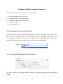
Chapter 9 Object General Properties ............................................................................................... 97
9.1 Selecting the Connection PLC Device............................................................................... 97
9.1.1 Setting the Reading and Writing Address............................................................... 97
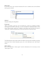
9.2 Using Shape Library and Picture Library .......................................................................... 99
9.2.1 Settings of Shape Library...................................................................................... 100
9.2.2 Settings of Picture Library .................................................................................... 101
9.3 Setting Text Content ........................................................................................................ 105
9.3.1 Adjusting Profile Size ........................................................................................... 109
9.4 Station Number’s Variable .............................................................................................. 110
9.4.1 Broadcast Station No. ........................................................................................... 111
Chapter 10 Security........................................................................................................................ 112
10.1 Settings of Password and Classes .................................................................................. 112
10.2 Object’s Security............................................................................................................ 114
10.3 Example of Security....................................................................................................... 118
2
Chapter 11 Index Register ............................................................................................................. 124
11.1 Introduction.................................................................................................................... 124
11.2 Example of Index Register............................................................................................. 124
Chapter 12 Keypad Design and Usage .......................................................................................... 128
12.1 Steps to Design a Pop-up Keypad.................................................................................. 128
12.2 Steps to Use Keypad without Title Bar.......................................................................... 131
12.3 Steps to Use Fixed Keypad ............................................................................................ 134
Chapter 13 Object .......................................................................................................................... 137
13.1 Bit Lamp Object............................................................................................................. 137
13.1.1 Overview............................................................................................................. 137
13.1.2 Configuration ...................................................................................................... 137
13.2 Word Lamp Object ........................................................................................................ 140
13.2.1 Overview............................................................................................................. 140
13.2.2 Configuration ...................................................................................................... 140
13.2.3 Restrictions ......................................................................................................... 143
13.3 Set Bit Object................................................................................................................. 144
13.3.1 Overview............................................................................................................. 144
13.3.2 Configuration ...................................................................................................... 144
13.4 Set Word Object............................................................................................................. 148
13.4.1 Overview............................................................................................................. 148
13.4.2 Configuration ...................................................................................................... 148
13.5 Function Key Object ...................................................................................................... 155
13.5.1 Overview............................................................................................................. 155
13.5.2 Configuration ...................................................................................................... 155
13.5.3 Non-ASCII character input ................................................................................. 158
13.6 Toggle Switch Object .................................................................................................... 162
13.6.1 Overview............................................................................................................. 162
13.6.2 Configuration ...................................................................................................... 162
13.7 Multi-Switch Object....................................................................................................... 165
13.7.1 Overview............................................................................................................. 165
13.7.2 Configuration ...................................................................................................... 165
13.8 Slide Object.................................................................................................................... 168
13.8.1 Overview............................................................................................................. 168
13.8.2 Configuration ...................................................................................................... 168
13.9 Numeric Input and Numeric Display Objects................................................................ 173
13.9.1 Overview............................................................................................................. 173
13.9.2 Configuration ...................................................................................................... 173
13.10 ASCII Input and ASCII Display Objects..................................................................... 181
3
13.10.1 Overview........................................................................................................... 181
13.10.2 Configuration .................................................................................................... 181
13.11 Indirect Window Object............................................................................................... 187
13.11.1 Overview........................................................................................................... 187
13.11.2 Configuration .................................................................................................... 187
13.11.3 Example to use indirect window....................................................................... 189
13.12 Direct Window Object ................................................................................................. 192
13.12.1 Overview........................................................................................................... 192
13.12.2 Configuration .................................................................................................... 192
13.12.3 Example ............................................................................................................ 194
13.13 Moving Shape Object .................................................................................................. 196
13.13.1 Overview........................................................................................................... 196
13.13.2 Configuration .................................................................................................... 196
13.14 Animation Object......................................................................................................... 201
13.14.1 Overview........................................................................................................... 201
13.14.2 Configuration .................................................................................................... 201
13.15 Bar Graph Object ......................................................................................................... 206
13.15.1 Overview........................................................................................................... 206
13.15.2 Configuration .................................................................................................... 206
13.16 Meter Display Object................................................................................................... 213
13.16.1 Overview........................................................................................................... 213
13.16.2 Configuration .................................................................................................... 213
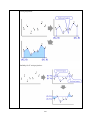
13.17 Trend Display Object................................................................................................... 221
13.17.1 Overview........................................................................................................... 221
13.17.2 Configuration .................................................................................................... 221
13.17.3 Example ............................................................................................................ 230
13.18 History Data Display.................................................................................................... 232
13.18.1 Overview........................................................................................................... 232
13.18.2 Configuration .................................................................................................... 232
13.18.3 Note................................................................................................................... 238
13.19 Data Block Display ...................................................................................................... 239
13.19.1 Overview........................................................................................................... 239
13.19.2 Configuration .................................................................................................... 240
13.19.3 On line operation............................................................................................... 245
13.20 XY Plot ........................................................................................................................ 251
13.20.1 Overview........................................................................................................... 251
13.20.2 Configuration .................................................................................................... 251
13.21 Alarm Bar and Alarm Display Objects........................................................................ 263
4
13.21.1 Overview........................................................................................................... 263
13.21.2 Configuration .................................................................................................... 263
13.22 Event Display Object ................................................................................................... 267
13.22.1 Overview........................................................................................................... 267
13.22.2 Configuration .................................................................................................... 267
13.23 Data Transfer (Trigger-based) Object.......................................................................... 274
13.23.1 Overview........................................................................................................... 274
13.23.2 Configuration .................................................................................................... 274
13.24 Backup ......................................................................................................................... 277
13.24.1 Overview........................................................................................................... 277
13.24.2 Configuration .................................................................................................... 277
13.25 Media Player Object .................................................................................................... 281
13.25.1 Overview........................................................................................................... 281
13.25.2 Configuration .................................................................................................... 281
13.25.3 Start / Stop playing video.................................................................................. 284
13.25.4 Media player setting guide................................................................................ 286
13.25.5 Restrictions ....................................................................................................... 291
13.26 Data Transfer (Time-based) Object ............................................................................. 292
13.26.1 Overview........................................................................................................... 292
13.26.2 Configuration .................................................................................................... 292
13.27 PLC Control Object ..................................................................................................... 295
13.27.1 Overview........................................................................................................... 295
13.27.2 Configuration .................................................................................................... 295
13.28 Schedule Object ........................................................................................................... 302
13.28.1 Overview........................................................................................................... 302
13.28.2 Configuration .................................................................................................... 302
13.28.3 Restrictions ....................................................................................................... 320
13.29 Option List ................................................................................................................... 321
13.29.1 Overview........................................................................................................... 321
13.29.2 Configuration .................................................................................................... 321
Chapter 14 Shape Library and Picture Library .............................................................................. 325
14.1 Creating Shape Library .................................................................................................. 325
14.2 Creating Picture Library ................................................................................................ 332
Chapter 15 Label Library and Using Multi-Language .................................................................. 340
15.1 Introduction.................................................................................................................... 340
15.2 Settings of Label Library’s Font .................................................................................... 341
15.3 How to Create a Label Library ...................................................................................... 343
15.4 Using Label Library....................................................................................................... 345
5
15.5 Use of Multi-Language .................................................................................................. 345
Chapter 16 Address Tag Library.................................................................................................... 347
16.1 Creating Address Tag Library ....................................................................................... 347
16.2 Using Address Tag Library............................................................................................ 350
Chapter 17 Transferring Recipe Data ............................................................................................ 351
17.1 Updating Recipe Data by Using Ethernet or USB cable ............................................... 351
17.2 Updating Recipe Data by Using CF Card or USB Stick ............................................... 352
17.3 Transferring Recipe Data............................................................................................... 353
17.4 Saving Recipe Data Automatically................................................................................ 353
Chapter 18 Macro Reference ......................................................................................................... 355
18.1 Macro Construction ....................................................................................................... 355
18.2 Syntax ............................................................................................................................ 356
18.2.1 Constants and Variables...................................................................................... 356
18.2.2 Operators............................................................................................................. 358
18.3 Statement........................................................................................................................ 360
18.3.1 Definition Statement ........................................................................................... 360
18.3.2 Assignment Statement ........................................................................................ 361
18.3.3 Logical Statements.............................................................................................. 361
18.3.4 Reiterative Statements ........................................................................................ 363
18.4 Function Blocks ............................................................................................................. 365
18.5 Build-In Function Block ................................................................................................ 366
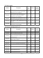
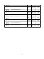
18.5.1 Mathematical Functions...................................................................................... 366
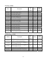
18.5.2 Data Transformation ........................................................................................... 371
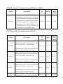
18.5.3 Data Manupulation.............................................................................................. 374
18.5.4 Bit Transformation.............................................................................................. 377
18.5.5 Communication................................................................................................... 379
18.6 How to Create and Execute a Macro ............................................................................. 390
18.6.1 How to Create a Macro ....................................................................................... 390
18.6.2 Execute a Macro ................................................................................................. 395
18.7 Some Notes about Using the Macro .............................................................................. 395
18.8 Use the Free Protocol to Control a Device .................................................................... 396
18.9 Compiler Error Message ................................................................................................ 401
18.10 Sample Macro Code..................................................................................................... 408
Chapter 19 How to Set HMI as a MODBUS Server ..................................................................... 413
19.1 How to Set HMI as MODBUS Device .......................................................................... 413
19.1.1 Creating a MODBUS Server .............................................................................. 413
19.1.2 How to Read From / Write to MODBUS Server................................................ 415
19.2 How to Change the Station Number of a MODBUS Server in Runtime....................... 417
6
Chapter 20 How to Connect a Barcode Device ............................................................................. 418
20.1 How to Connect a Barcode Device................................................................................ 418
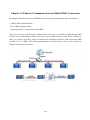
Chapter 21 Ethernet Communication and Multi-HMIs Connection.............................................. 422
21.1 HMI to HMI Communication ........................................................................................ 423
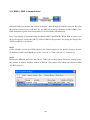
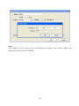
21.2 PC to HMI Communication ........................................................................................... 425
21.3 Operate the PLC Connected with other HMIs............................................................... 429
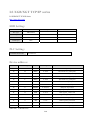
Chapter 22 System Reserved Words / Bits .................................................................................... 432
22.1 System Status and Control ............................................................................................. 432
22.2 States of Data Input........................................................................................................ 433
22.3 Recipe Data.................................................................................................................... 433
22.4 Task Button and Fast Selection Window....................................................................... 434
22.5 Event Logging................................................................................................................ 434
22.6 Data Logging ................................................................................................................. 435
22.7 Password and Operation Level ...................................................................................... 435
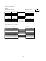
22.8 Time of HMI .................................................................................................................. 437
22.9 Hardware of HMI........................................................................................................... 437
22.10 The States of Communicating with Remote HMI(s) ................................................... 438
22.11 The States of Communicating with PLC ..................................................................... 438
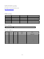
22.12 Client Connected to Server .......................................................................................... 440
22.13 MODBUS Server Station no........................................................................................ 441
22.14 COM Communication.................................................................................................. 441
22.15 File Manager ................................................................................................................ 443
22.16 PLC & Remote HMI IP Address Setting..................................................................... 443
22.17 Printer Server Setting................................................................................................... 443
22.18 Address Index Function ............................................................................................... 444
22.19 The Address Ranges of Local HMI Memory .............................................................. 444
22.19.1 Bits .................................................................................................................... 444
22.19.2 Words................................................................................................................ 445
22.20 Touch Screen X and Y Position................................................................................... 446
22.21 Variable Station no. ..................................................................................................... 446
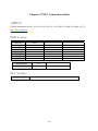
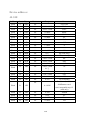
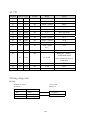
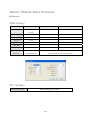
Chapter 23 PLC Connection Guide ............................................................................................... 447
AIBUS.................................................................................................................................... 447
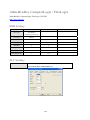
Allen-Bradley CompactLogix / FlexLogix............................................................................ 450
Allen-Bradley DF1................................................................................................................. 455
Allen-Bradley DH485............................................................................................................ 457
Allen-Bradley EtherNet/IP CompactLogix............................................................................ 460
Allen-Bradley EtherNet/IP (DF1).......................................................................................... 463
Allen Bradley PLC5............................................................................................................... 466
7
Baumuller Servo .................................................................................................................... 468
Copley Controls ..................................................................................................................... 470
DELTA DVP ......................................................................................................................... 472
FATEK FB series................................................................................................................... 474
GE Fanuc SNP-X................................................................................................................... 477
GE Fanuc Series 90-30 (Ethernet) ......................................................................................... 480
HAN YOUNG ....................................................................................................................... 483
Heng Yuan Sensor ................................................................................................................. 484
HITACHI H series (CPU port) .............................................................................................. 485
IDEC ...................................................................................................................................... 490
KEYENCE KV series ............................................................................................................ 492
KEYENCE KV-1000............................................................................................................. 494
Korenix 6550 / 6520 .............................................................................................................. 496
KOYO DirectLogic................................................................................................................ 498
LS MASTER-K Cnet............................................................................................................. 502
LS MASTER-K300S CPU .................................................................................................... 504
LS XGB/XGT ........................................................................................................................ 506
LS XGB/XGT TCP/IP series ................................................................................................. 508
LIYAN EX series................................................................................................................... 510
Master (Master-Slave Protocol)............................................................................................. 512
Memobus (YASKAWA MP Series controllers).................................................................... 515
MITSUBISHI AJ71 ............................................................................................................... 517
MITSUBISHI FX0n/FX2 ...................................................................................................... 519
MITSUBISHI FX2n............................................................................................................... 521
MITSUBISHI FX232/485BD................................................................................................ 523
MITSUBISHI FX3U.............................................................................................................. 526
MITSUBISHI FX3U-ETHERNET........................................................................................ 528
MITSUBISHI Q02H.............................................................................................................. 535
MITSUBISHI Q06H.............................................................................................................. 537
MITSUBISHI QJ71 ............................................................................................................... 539
MITSUBISHI QJ71E71......................................................................................................... 543
MODBUS ASCII ................................................................................................................... 550
MODBUS RTU ..................................................................................................................... 552
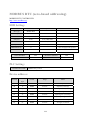
MODBUS RTU (zero-based addressing) .............................................................................. 555
MODBUS SERVER (Modbus RTU Slave) .......................................................................... 559
MODBUS TCP/IP ................................................................................................................. 561
MODBUS TCP/IP (zero-based) ............................................................................................ 563
Modicon Twido...................................................................................................................... 565
8
OMRON C/CQM1 series....................................................................................................... 567
OMRON CJ1/CS1 ................................................................................................................. 569
OMRON CJ1/CS1 Ethernet................................................................................................... 571
OMRON E5CN...................................................................................................................... 574
Panasonic FP.......................................................................................................................... 576
Parker Compax3..................................................................................................................... 580
SAIA PCD PGU mode........................................................................................................... 584
SAIA PCD S-Bus mode......................................................................................................... 586
SEW Eurodrive MOVITRAC................................................................................................ 588
SIEMENS S7/200 .................................................................................................................. 589
SIEMENS S7/200 Ethernet.................................................................................................... 591
SIEMENS S7/300 .................................................................................................................. 593
SIEMENS S7/300 Ethernet.................................................................................................... 595
SIMATIC TI505 .................................................................................................................... 597
Telemecanique UniTelWay ................................................................................................... 599
TOSHIBA T series................................................................................................................. 601
TOSHIBA TC mini series...................................................................................................... 603
TOSHIBA VF-S11................................................................................................................. 605
VIGOR................................................................................................................................... 607
Yokogawa FA-M3 ................................................................................................................. 609
Yokogawa FA-M3 (Ethernet) ................................................................................................ 615
Chapter 24 MT8000 Supports Printers .......................................................................................... 617
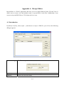
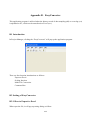
Appendix A. Recipe Editor............................................................................................................ 619
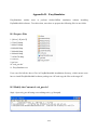
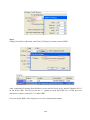
A.1 Introduction..................................................................................................................... 619
A.2 Setting of Recipe Editor.................................................................................................. 621
Appendix B. EasyConverter .......................................................................................................... 623
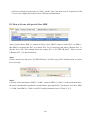
B.1 Introduction ..................................................................................................................... 623
B.2 Setting of EasyConverter ................................................................................................ 623
B.2.1 How to Export to Excel........................................................................................ 623
B 2.2 How to Use Scaling Function............................................................................... 626
B.2.3 How to Use Multi-File Conversion...................................................................... 628
B.3 Enable Setting File .......................................................................................................... 629
B.3.1 For “Combination” and “Enable Setting File”..................................................... 632
B.4 Command Line................................................................................................................ 634
Appendix C. EasyPrinter ............................................................................................................... 635
C.1 Using EasyPrinter as a Printer Server ............................................................................. 636
C.1.1 Setup Procedure in EasyPrinter............................................................................ 636
C.1.2 Setup Procedure in EasyBuilder8000................................................................... 637
9
C.2 Using EasyPrinter as a Backup Server............................................................................ 639
C.2.1 Setup Procedure in EasyPrinter............................................................................ 639
C.2.2 Setup Procedure in EasyBuilder8000................................................................... 641
C.3 EasyPrinter Operation Guide .......................................................................................... 643
C.3.1 Appearance........................................................................................................... 643
C.3.2 Operation Guide ................................................................................................... 644
C.4 Convert Batch File .......................................................................................................... 650
C.4.1 The Default Convert Batch File ........................................................................... 650
C.4.2 Specialized Criteria .............................................................................................. 651
C.4.3 The Format of a Convert Batch File..................................................................... 652
C.4.4 The Order of Examining Criteria ......................................................................... 652
Appendix D. EasySimulator .......................................................................................................... 654
D.1 Prepare Files.................................................................................................................... 654
D.2 Modify the Content of xob_pos.def ................................................................................ 654
Appendix E. Multi-HMIs Intercommunication (Master-Slave Mode) .......................................... 656
E.1 How to Create a Project of Master HMI ......................................................................... 656
E.2 How to Create a Project of Slave HMI............................................................................ 657
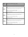
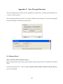
Appendix F. Pass-Through Function ............................................................................................. 660
F.1 Ethernet Mode ................................................................................................................. 660
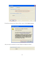
F.1.1 How to Change the Virtual Serial Port ................................................................. 662
F.1.2 How to Use Ethernet Mode .................................................................................. 664
F.2 COM Port Mode .............................................................................................................. 667
F.2.1 Settings of COM Port Mode ................................................................................. 667
F.2.2 HMI Work Mode .................................................................................................. 669
F.3 Using System Reserved Addresses to Enable Pass-Through Function ........................... 672
10
Chapter 1 EasyBuilder 8000 Installation and Startup Guide
1.1 EasyBuilder 8000 Installation
Software:
Download EasyBuilder 8000 configuration software from EasyBuilder 8000 CD or visiting
Weintek Labs, Inc.’s website at http://www.weintek.com to obtain all software versions
available (including Simplified Chinese, Traditional Chinese, French, Korean, Italian, Spanish
and English version) and latest upgraded files.
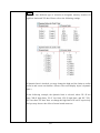
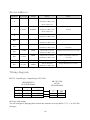
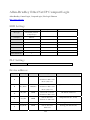
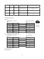
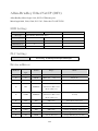
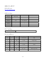
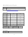
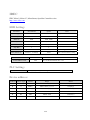
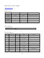
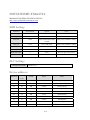
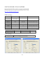
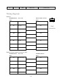
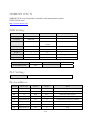
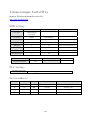
Hardware Requirements (Recommended):
CPU: INTEL Pentium II or above
Memory: 64MB or above
Hard Disk: 2.5GB or above (Disc space available at least 10MB)
CD-ROM: 4X or above
Display: 256 color SVGA with 800 x 600 resolution or greater
Keyboard and Mouse
Ethernet: for project downloading/uploading
RS-232 COM: At least one available RS-232 serial port required for on-line simulation
Printer
Operating System:
Windows 2000/Windows NT/Windows XP/Windows Vista
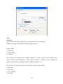
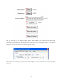
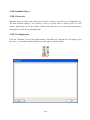
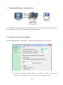
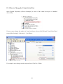
1.2 Steps to Install EasyBuilder 8000
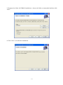
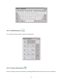
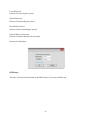
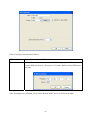
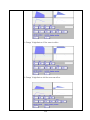
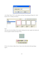
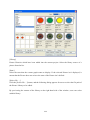
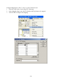
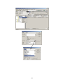
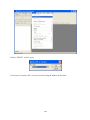
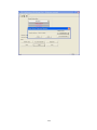
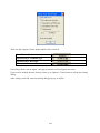
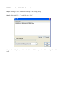
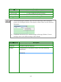
1. Installing EasyBuilder 8000:
Put the EasyBuilder Installation CD into the CD drive. The autorun should bring up a screen
showing an area to click to begin the Easybuilder installation. If the Autorun sequence does not
start, browse the CD, find the root directory of [Autorun.exe] manually.
11
`
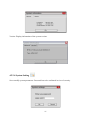
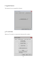
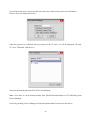
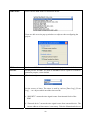
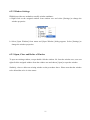
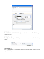
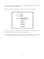
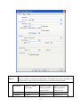
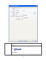
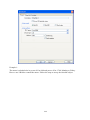
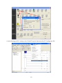
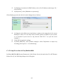
2. Choose [Install] and click “Next” to follow the installation instructions.
12
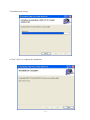
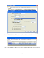
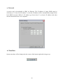
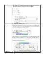
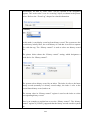
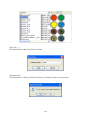
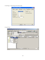
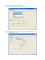
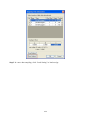
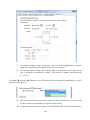
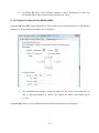
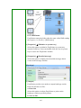
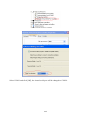
3. Designate the folder for EB8000 installation or choose the folder recommended and then click
“Next”.
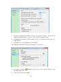
4. Click “Next” to confirm the installation.
13
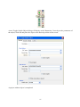
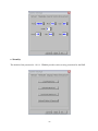
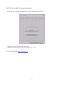
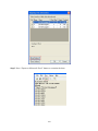
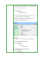
5. Installation processing.
6. Click” Close” to complete the installation.
14
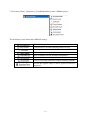
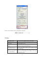
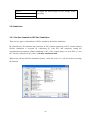
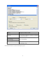
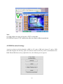
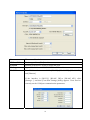
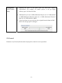
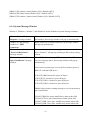
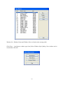
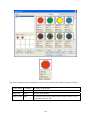
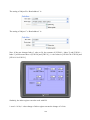
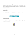
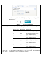
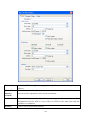
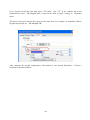
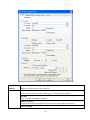
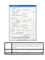
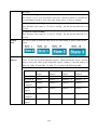
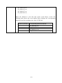
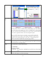
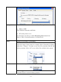
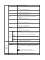
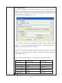
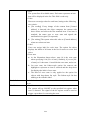
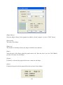
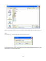
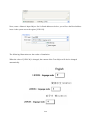
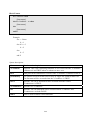
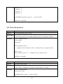
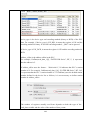
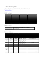
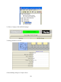
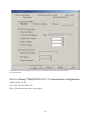
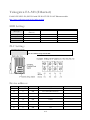
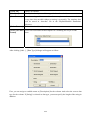
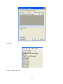
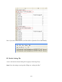
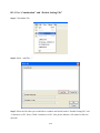
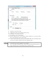
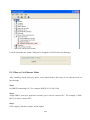
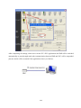
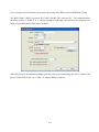
7. From menu [Start] / [Programs] / [EasyBuilder8000] to start a EB8000 project.
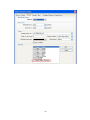
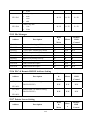
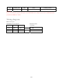
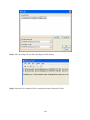
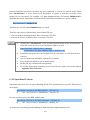
The definition of each menu under EB8000 catalog:
EB8000 editing software
Conversion tool for Data sampling and Event Log
Remote printer server
EB8000 project management
Note of EB8000 version and latest information
Communication monitoring tool via online simulation
Tool for executing simulation without installing EB8000
Review the register range of device types for each PLC
supported
15
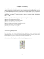
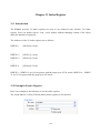
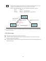
Chapter 2 Project Manager Operations
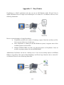
The Project Manager is a software shell for launching several utilities. Some functions are
duplicated in the EasyBuilder 8000 screen-editing program. Project Manager program can be run
as a stand-alone program.
In this chapter, each function will be introduced respectively.
16
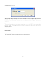
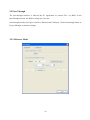
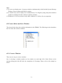
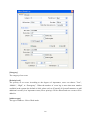
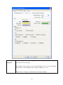
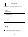
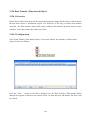
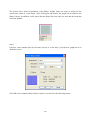
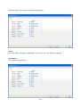
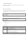
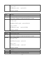
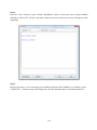
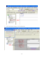
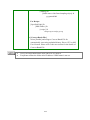
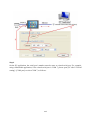
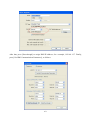
2.1 HMI IP, Password
When operating HMI by Ethernet, users need to designate the correct IP address and password in
HMI. “Reset” and “Download” functions share a set of password while “Upload” function uses
another set.
The password provides protection against unauthorized access to the HMI. Be sure to record any
password change. If resetting password to default, the project and data on the HMI will be
completely erased.
Reboot HMI
The "Reboot HMI" feature is designed for users to reboot the project.
17
Set the correct IP address when operate HMI via Ethernet.
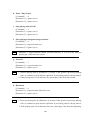
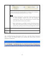
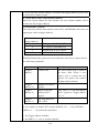
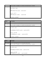
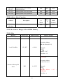
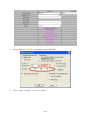
2.2 Editor
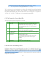
EasyBuilder 8000
To launch the EasyBuilder 8000 screen editor
EasyConverter
Conversion tool for Data Sampling and Event Log
EasyPrinter
Remote printer server.
Recipe / Extend Memory
Editor
Provide file format conversion and data editing
function for Recipe/Extend Memory
EasyAddressViewer
Review the register range of device types for each
PLC supported
Build Download Data for
CF Card/USB Disk
Except for Ethernet and USB cable, the project and
data can be downloaded to the HMI by CF card or
USB memory stick
18
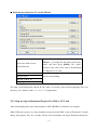
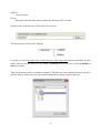
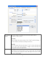
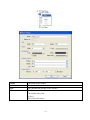
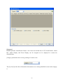
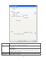
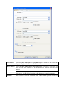
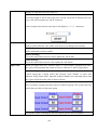
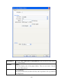
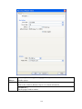
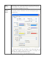
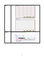
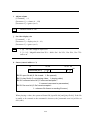
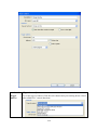
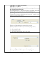
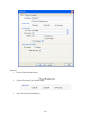
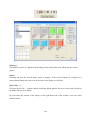
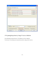
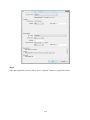
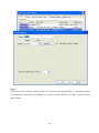
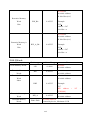
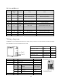
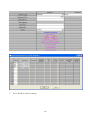
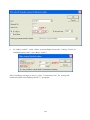
* Build Download Data for CF Card/USB Disk
Insert CF card or USB stick to PC and press
Select the folder to save
download data
Project
Recipe (RW)
[Browse…] to assign the file path (or directory
name) and then press [Build]. The whole
content of the source files will be downloaded
to USB stick or CF card
Press [Browse…] to assign the desired specific
files for downloading.
Recipe A (RW_A)
Data log
The path of download data should be the name of directory and avoid designating only root
directory. For example, either “c:\\” or “f:\\” is illegal name.
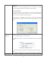
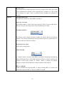
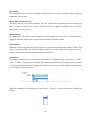
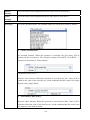
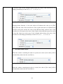
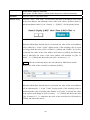
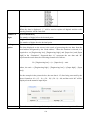
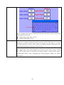
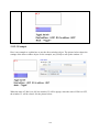
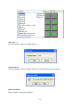
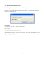
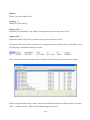
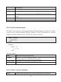
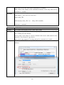
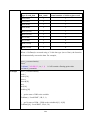
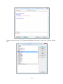
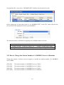
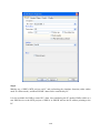
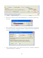
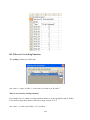
2.2.1 Step by Step to Download Project Via USB or CF Card
Take downloading data to the folder named as “123” (K:\123) in USB stick for example.
When USB stick (project or recipe included) is inserted to the HMI, a pop-up Download / Upload
dialog will appears after few seconds. Please select Download and input Download Password.
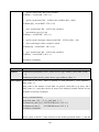
19
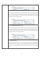
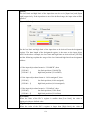
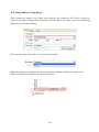
Check Download project files and Download historical files on Download Settings dialog, and
then press OK. After that, Pick a Directory dialog will appear. Please select directory:
usbdisk/device-0/123 and then press OK. Project will be automatically updated.
Note: It’s necessary to reboot HMI even if historical file is downloaded only.
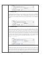
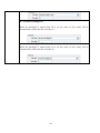
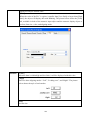
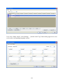
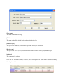
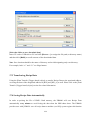
2.3 Transfer
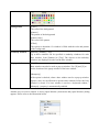
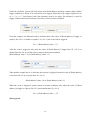
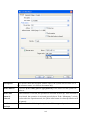
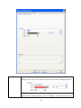
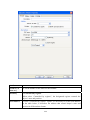
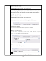
2.3.1 Download
Download source files to the HMI through Ethernet or USB cable. Press the [Download] button
and the dialog displays as below:
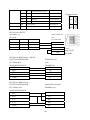
Firmware
Check [Firmware] to update all of the
kernel programs of HMI.
20
Note: It is necessary when the latest
EB8000 version is first-time download.
Project
RW
To assign the desired specific path for file
downloading
RW_A
Data log
Install X-series media-player drivers
It is necessary when the EB8000 is
first-time download to X series.
Reboot HMI after download
Automatically
downloading
Reset recipe
Check the box to erase the specific files in
HMI before downloading process
Reset event log
reboot
HMI
after
Reset data log
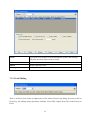
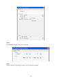
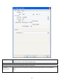
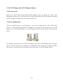
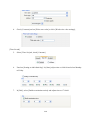
2.3.2 Upload
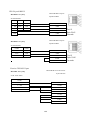
Upload files from HMI to PC by Ethernet or USB cable and the dialog box shows as below:
21
Project
RW
To assign the desired path for file storage before
uploading.
RW_A
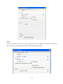
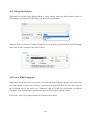
2.4 Simulation
2.4.1 On-line Simulation/Off-line Simulation
There are two types of simulations: Off-line simulation & On-line simulation.
By virtual device, PC simulates the operations of PLC without connecting to PLC. On the contrary,
On-line simulation is executed by connecting PC with PLC and accurately setting the
communication parameters. When simulating on PC, if the control target is a local PLC (i.e. the
PLC directly connected to PC), there is 10 mins simulation limit.
When using On-line/Off-line Simulation feature, select the source of *.xob file before executing
the function.
22
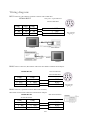
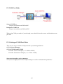
2.5 Pass-Through
The pass-through function is allowed the PC application to connect PLC via HMI. In the
pass-through function, the HMI is acting as a converter.
Pass-through provides two types of modes: Ethernet and COM port. Click Pass-through button on
Project Manager to start the settings.
2.5.1 Ethernet Mode
23
2.5.2 COM Port Mode
24
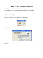
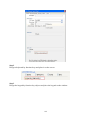
Chapter 3 Create a EasyBuilder 8000 Project
In this Chapter, we will take Mitsubishi PLC as an example to illustrate how to create and compile
a new EB8000 project, do the simulation on PC and download the project to the HMI.
3.1 Create a New Project
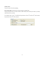
First of all, click [New] icon on the toolbar to create a new project.
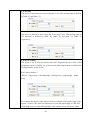
Select HMI Model, check Use template and then click OK.
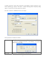
Under Device Tab, click [New…] button to correctly set up the device property for communicating
to the PLC.
25
Device “MISUBISHI FX0n/FX2” is added to the Device Table after click OK.
Now, if users would like to add a new object, such as Toggle Switch, click the icon on the tool bar.
26
A new Toggle Switch Object dialog will display as the illustration. Correctly set the parameters of
the object, click OK and place the object to the desired position of the screen.
A project with an object is completed.
27
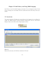
3.2 Save and Compile the Project
In the menu, select File/Save to save the project. After the .mtp file is saved, select Tools/Compile
or click [Compile] icon to compile the project and check if the screen configuration is correct.
A .xob file will be obtained after compiling.
A successfully compiled file will get the dialog as below:
28
3.3 Simulate the Project Either On-line or Off-line
There are two types of simulation: Off-line simulation & On-line simulation. By virtual device, PC
simulates the operations of PLC without connecting to PLC. On the contrary, On-line simulation is
executed by connecting PC with PLC and accurately setting the communication parameters. When
simulating on PC, if the control target is a local PLC (i.e. the PLC directly connected to PC),
there’s a 10 minutes limit.
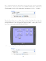
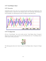
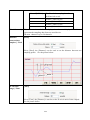
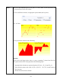
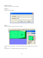
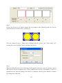
3.3.1 Off-line Simulation
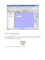
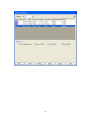
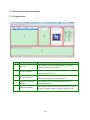
Click [Off-line Simulation] icon to execute the Off-line Simulation.
From this example, we got the Off-line simulation screen as below.
29
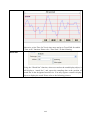
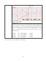
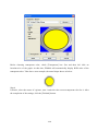
3.3.2 On-line Simulation
Click [On-line Simulation] icon to do the on-line simulation after correct connecting the device.
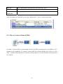
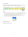
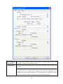
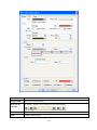
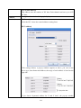
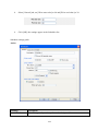
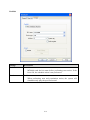
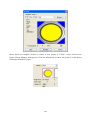
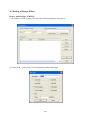
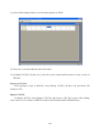
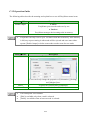
3.4 Download the Project
In the menu, select Tool/Download…or click [Download] icon from tool bar to load the image
file into the HMI. Before downloading, be sure to check the selections in the dialog correctly.
30
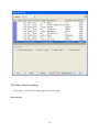
HMI IP
Assign the IP address of HMI
Password
Input the password
Firmware
It’s necessary if update the firmware or download
the project at first time
Reset recipe
If the selection is checked, the file will be erased
before downloading
Reset event log
Reset data log
Reboot HMI after download
If the selection is checked, HMI will reboots after
downloading is done
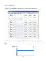
Click Download button to start downloading the project.
31
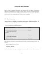
Chapter 4 Hardware Settings
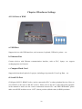
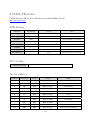
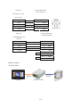
4.1 I/O Ports of HMI
a. USB Host
Support devices with USB interfaces, such as mouse, keyboard, USB stick, printer…etc.
b. Ethernet Port
Connect devices with Ethernet communication interface, such as PLC, laptop…etc; support
exchanging data via Network.
c. Compact Flash Card
Support the download/ upload of a project, including recipe transfer, Event Log Data…etc.
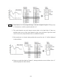
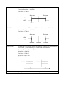
d. Serial I/O Port
COM ports, RS-232, RS485-2w/4w, can be connected to PLC or other peripheral devices. Here we
view RS-422 as the same as RS-485 (4 wire). Please refer to the PLC connecting guide appendix
in the manual to make sure the correct connection between PLC and HMI. Meanwhile, please
make sure all DIP switches are on “OFF” (down) position (default value) in HMI operations.
32
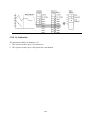
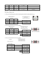
In addition, Weintek provides [MT8-COM1 Multi-Connector cable] and [MT8-COM3
Multi-Connector cable] to expand one COM port to multiple independent COM ports so that the
efficiency of the operation will be improved.
4.2 HMI System Settings
Before operating HMI, users have to complete the HMI system settings. After the setup, use
EB80000 editing software to develop a personal operation interface. The following illustrates each
system setting respectively.
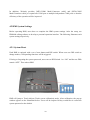
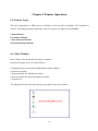
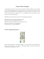
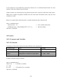
4.2.1 System Reset
Each HMI is equipped with a set of reset button and DIP switch. When users use DIP switch to
change modes, corresponding functions will be triggered.
If losing or forgetting the system password, users can set DIP Switch 1 to “ON” and the rest DIPs
remain “OFF”. Then reboot HMI.
HMI will jump to Touch Adjust (Touch screen calibration) mode. After calibration, the pop-up
window appears as the illustration below. Users will be inquired if they would like to restore the
system password to the default.
33
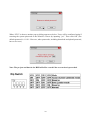
When “YES” is chosen, another pop-up dialog appears as below. Users will be confirmed again if
restoring the system password to the default is correct by inputting ”yes”. Then click OK. (The
default password is 111111. However, other passwords, including download and upload password,
have to be reset.)
Note: The project and data in the HMI will all be erased if the reset action is proceeded.
34
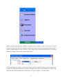
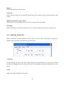
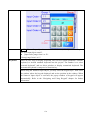
4.2.2 Tool bar
When the HMI is booted, user can set the system by using the mouse to click tool bar at the bottom
of the screen. Normally, tool bar is hidden automatically. Only by touching the target at the corner
of the right-bottom will the tool bar pops up.
4.2.2.1 Large Keyboard
Use large keyboard to input the text information.
35
4.2.2.2 Small Keyboard
Use small keyboard to input the numerical information.
4.2.2.3 System Information
Network: Display Network information, including HMI IP address and other network information.
36
Version: Display information of the system version.
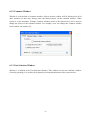
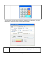
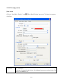
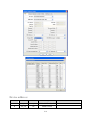
4.2.2.4 System Setting
Set or modify system parameters. Password has to be confirmed in view of security.
37
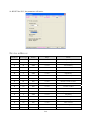
a. Network
A project can be downloaded to HMI via Ethernet. The IP address of target (HMI) must be
correctly set. If “Auto Get IP Address” is selected, IP address will be automatically assigned from
local DHCP network. While if “IP address get from below” is selected, IP address and other
network information have to be inputted.
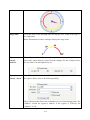
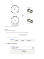
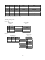
b. Time/Date
System time/date will be displayed at the corner of the bottom-right after being set up.
38
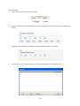
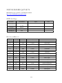
c. Security
The default of the password is 111111. EB8000 provides strict security protection for the HMI.
39
Local Password
Password for entering the system
Upload Password
Password for uploading the project
Download Password
Password for downloading the project
Upload (History) Password
Password for uploading the historical data
Password confirmation:
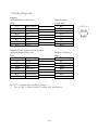
d. History
The tab to clear the historical data in the HMI: Recipe, Event log and Data log.
40
e. Miscellaneous
Use the rolling bottom on the screen to adjust the brightness of the LCD.
41
f. Upgrade firmware
The function for users to upgrade the firmware.
g. CF card Status
When new CF card device is detected, this function will be enabled.
42
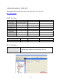
h. VNC server (for X series and i series)
The function is to monitor and control the remote HMI through Ethernet.
1. Enable VNC server and set the password.
2. Install Java for Internet Explorer or install VNC viewer.
For IE, enter HMI IP: http://192.168.1.28
43
For VNC viewer, enter HMI IP address and the password.
44
Note:
(1) Only allow one user to log in to VNC at one time.
(2) HMI will reject VNC connection after one hour without operations.
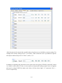
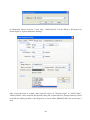
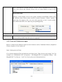
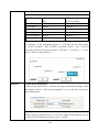
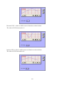
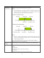
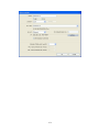
4.3 HMI Download Settings
A project or data can be downloaded to HMI via CF card or USB stick. Insert CF card or USB
stick and designate the directory path. All contexts under the directory will be downloaded to the
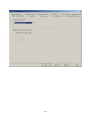
HMI. When HMI detects new peripheral devices, the following screen appears:
45
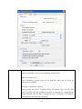
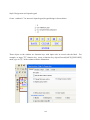
Several functions can be selected at this time and some of them need password confirmation.
Please refer to the illustration below:
After the password is confirmed, directory names of the CF card…etc will be displayed. (PCcard:
CF Card ; USB disk: USB device)
Select the download path and click OK for downloading.
Note: Users have to create download data from [Build Download Data for CF/USB Disk] from
Project Manager.
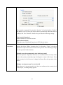
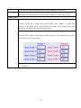
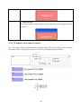
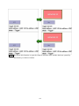
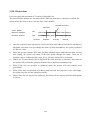
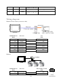
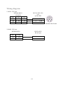
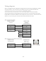
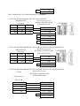
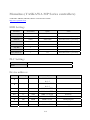
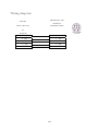
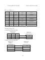
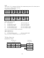
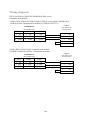
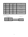
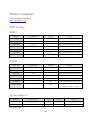
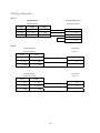
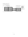
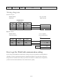
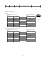
Generally speaking, Project Manager divides the downloaded files into two directories:
46
MT8000
Project storage
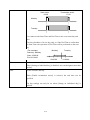
History
When users download the historical data, the directory will be created.
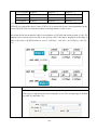
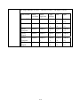
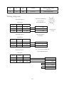
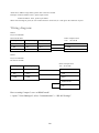
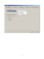
In other words, if the directory of the target file as below,
The data structure is like below diagram:
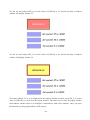
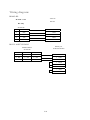
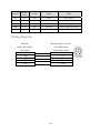
Users have to select the upper layer of the directory of the target file when downloading. In other
words, take the structure above as an example, download must be selected. Choosing mt8000 or
history is invalid.
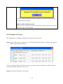
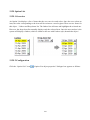
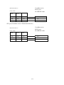
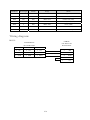
Take the illustration below as another example: USB disk only store mt8000 directory but don’t
includes history. In this case, user must choose device-0 to correctly download the file.
47
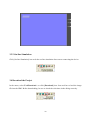
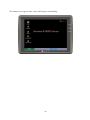
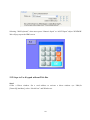
The startup screen appears after a successful project downloading.
48
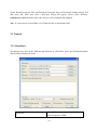
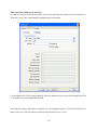
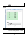
Chapter 5 System Parameters
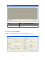
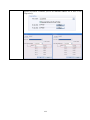
In the EB8000, select menu [Edit] / [System Parameters…] and the System Parameter Settings
dialog appears:
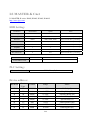
System Parameter Settings are divided into seven parts: [Device], [Model], [General], [Security],
[Font], [Extend Memory] and [Printer Server], which are introduced respectively in this
chapter.
49
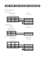
5.1 Device
[Device] parameters determine all of the characteristics of each device controlled by a HMI. The
device can be a PLC, remote HMI or PC. When opening a new *.mtp file, a default device: “Local
HMI” is shown in the table. That is to say the device table must have a “Local HMI” at least, and it
is used to identify current HMI.
The procedure to create a new device:
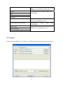
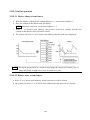
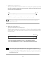
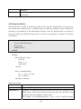
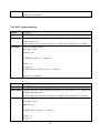
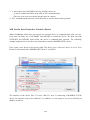
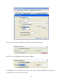
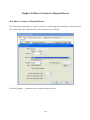
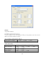
5.1.1 How to Control a Local PLC
So-called “local PLC” means a PLC which is connected to a local HMI directly. To control a local
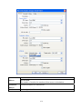
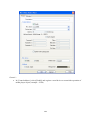
PLC, users need to add this type of device first. Click [New…] and the [Device Properties] dialog
appears. Correctly filling in all of the properties is required.
Here is an example of MITSUBISHI FX0n/FX2 local PLC:
50
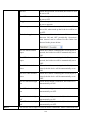
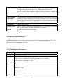
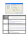
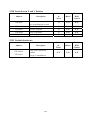
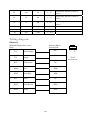
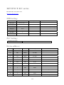
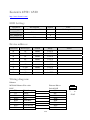
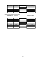
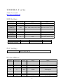
Name
The name of the device
HMI or PLC
Device type. Select [PLC] in this case.
Location
Position of the device. Select [Local]in this case.
PLC type
Type of PLC. Select MITSUBISHI FX0n/FX2 in this case
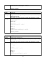
PLC I/F
Four PLC interfaces are available: [RS-232], [RS-485 2W], [RS-485 4W],
and [Ethernet].
If the interface is [RS-232], [RS-485 2W],or [RS-485 4W], click
[Settings…] and then [Com Port Settings] dialog appears. Users need to
correctly set the COM port communication parameters.
51
[Timeout]
Window No.5 will pop up and appear the “PLC No Response” message
once the response time from PLC to HMI over timeout setting.
[Turn around delay]
The delayed interval of two commands. i.e. the next command will be
delayed as the setting required to be sent out after the previous command is
sent. If no specific request, the default setting is 0.
If the interface is [Ethernet], click [Settings…] and then [IP Address
Settings] appears. Users need to correctly set IP address and Port No. of the
PLC.
PLC default
station no.
If the device address of the object doesn’t include station no., EB8000 will
use PLC default setting no. as PLC station no.
In addition, PLC station no. can put in device address directly, for example,
1#20
“1” means PLC station no, and has to be named more than 0 and less than
255.
“20” means PLC address, the “#” sign is to separate station no. and address.
Use broadcast
For example, set broadcast value as 255.For device address of 255#20, the
52
command
HMI will send command to PLC but PLC won’t deliver any response to
HMI.
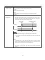
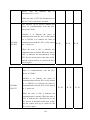
Interval of block
pack (words)
If the interval of read out address between different commands is less than
this value, these commands can be combined to one. But combination
function is disabled if this value is 0.
For example, the interval value is set as 5 and users would like to read out 1
word from LW3 and 2 words from LW6 respectively. Since the interval of
addresses between LW3 and LW6 is less than 5, these two commands can
be combined to one. The contents of combination command therefore
becomes 5 consecutive words from LW3 (read out from LW3~LW7).
Note: Max. combination command must less than [Max. read-command
size].
Max.
read-command
size (words)
The Max. data size to be read out from device at one time. Unit: word
Max.
write-command
size (words)
The Max. data size to be wrote in to device at one time. Unit: word.
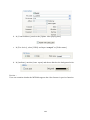
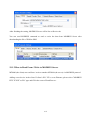
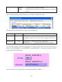
After all settings are completed, a new name “Local PLC” device is listed on the table.
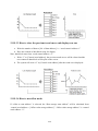
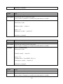
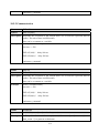
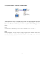
5.1.2 How to Control a Remote PLC
53
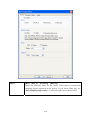
So-called “remote PLC” means a PLC connected to a remote HMI. To control a remote PLC, users
need to add this type of device. Click [New…] and the following [Device Properties] dialog
appears. Correctly fill in all of the properties are required.
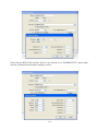
Here take a remote PLC, SIEMENS S7/200, as an example:
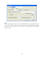
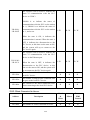
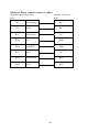
Each of parameters is introduced as follows:
Location
Select [Remote] in this case and set the IP address of the remote HMI which
is connected to SIEMENS S7/200 PLC. Click [Settings…] to set the IP
address of the remote HMI
PLC Type
Type of PLC. Select SIEMENS S7/200 in this case.
54
PLC I/F
The setting defines which interface the remote PLC uses.
COM
The setting defines which COM port the remote PLC uses.
PLC default
station no.
The setting defines which the PLC default station the remote PLC uses.
After all settings are completed, a new name “Remote PLC” device is listed on the table.
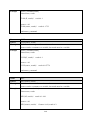
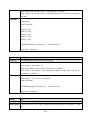
5.1.3 How to Control a Remote HMI
So-called “a remote HMI” means through network, the HMI is controlled by a local HMI or a PC
running on-line simulation. To control a remote HMI, users should add this type of device. Click
[New…] and the following [Device Properties] dialog appears. Correctly fill in all of the properties
are required.
55
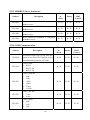
Each of settings is introduced as follows:
HMI or PLC
Type of device. Select HMI in this case.
Location
Select [Remote] in this case and click [Settings…] to set IP address of
remote HMI and Port no. The port no. of remote HMI and local HMI must
be same.
After all settings are completed, a new name “Remote HMI” device is listed on the table.
56
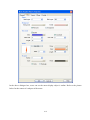
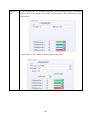
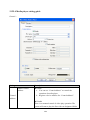
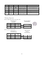
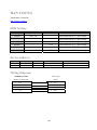
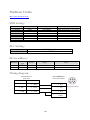
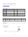
5.2 Model
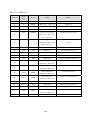
Parameters on [Model] tab determine the HMI model, timer source and printer.
57
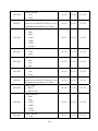
HMI model
Select current HMI model as illustration below.
Users are able to resize pop-up windows or objects when configuring the
project.
HMI station no.
Set the no. of HMI station. If with no particular purpose, select default.
Port no.
Set the port no. for HMI. It is used as MODBUS server’s port no. If with no
particular purpose, select default.
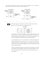
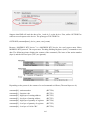
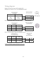
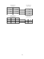
Timer
[Clock source]
Set the source of timer. The timer is used by such as [Data Log], [Event
Log] ….etc. objects which need the time records.
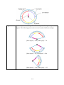
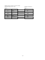
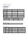
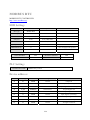
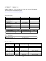
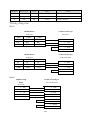
a. “HMI RTC” means the time signal comes from internal clock of the
HMI.
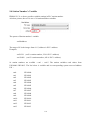
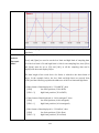
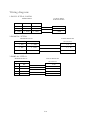
b. “External device” means the time signal comes from external device. The
correct address of time source is necessary. Take the illustration below as
58
an example: “TV” indicates the time from Local PLC. The context of 6
consecutives addresses starting from 0 shows as follows:
TV 0
→ Sec.
TV 1
→ Min.
TV 2
→ Hr.
TV 3
→ Day
TV 4
→ Month
TV 5
→ Year
Printer
[Type]
Display printer supported. For HP PCL Series, it has to use USB interface
while other printers have to use COM interface. For more details, please
refer to the “MT8000 support printer” chapter.
Using COM port to connect printer has to set accurate parameters. When
the type of printer is SP-M, D, E, F, the [pixels of width] has to set
accurately, i.e. the setting can not exceed printer’s default setting. Otherwise
the printing result will be incorrect.
Storage space
1. Storage space available for the project and historical data is 12MB. By
59
management
( For T series
only)
adjusting the space of two parts, users can reach their memory
requirements. For example, for smaller project, it can get bigger
memory space for historical data.
2. Minimum Project size is 6MB; Maximum Project size is 10 MB (default
is 8MB).Minimum Historical data size is 2MB; Maximum Historical
data size is 6 MB (default is 4MB).
3. Users have batter to copy and erase the original historical data in HMI
before the storage space is changed.
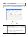
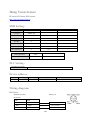
5.3 General
Parameters in [General] tab determine all properties related to screen operations.
60
Fast selection
button
Define the settings of all attributes for fast selection window which is
designated as window number 3.
[Attribute]
Enable or disable fast selection window. Select “Enable” and click [Settings…]
to set the attributes of the button, including color and text.
[Position]
Select the location of the fast select button. If “Left” is chosen, the button will
show up at the corner of the left-bottom; if “Right” is chosen, the button will
show up at the corner of the right-bottom.
Screen saver
[Back light saver]
If the duration of no touch operation on screen is equal to this value, back light
will be turned off. The setting unit is minute. Back light will be turned on when
the screen is touched again.
61
[Screen saver]
If the duration of no touch operation on screen is equal to this value, the current
screen automatically switches to the assigned [Saver window no.]. The setting
unit is minute. If “none” value is selected, [Saver window no.] function is
disabled.
Option
[Startup window no.]
Designate the window no. after HMI is started up.
[Extra no. of events]
The default number of the event in the system is 1000. If users would like to
add more records, the setting value can be modified up to 10000.
[Common window]
The objects on the common window (window 4) will be shown on each base
window. This selection determines the layers these objects are placed above or
below the objects of the base window.
[Keyboard caret color]
Set the color of input caret.
[Object layout]
If “Control” mode is selected, when HMI is operated, [Animation] and [Moving
Shape] will display above other kinds of objects which is with no relation to the
sequence of the object created. If “Nature” mode is selected, the display
sequence of objects will follow the creation sequence of the objects.
[RW_A enabled]
Enable or disable the recipe data RW_A. After activating RW_A, an object can
control the content of RW_A. The size of RW_A is 64K.
62
Keyboard
If users would like to create a new keyboard, keyboard should be configured on
the existing window. Select [Add…] to add these windows to the list.
Please refer to the “designing and using keypad” chapter for details.
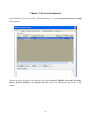
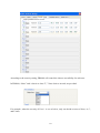
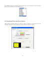
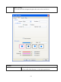
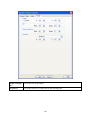
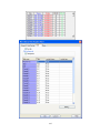
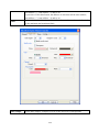
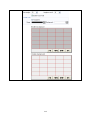
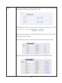
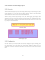
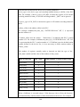
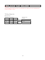
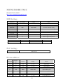
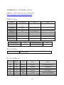
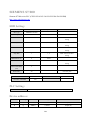
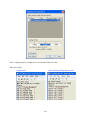
5.4 Security
Parameters in [Security] tab determine the classes accessible for each user and users’ passwords.
Up to twelve passwords can be set. Only numerals are acceptable for the password and the range is
from 0~999999999.
63
According to the security setting, EB8000 will control the classes accessibility for each user.
In EB8000, “None” and “class A to class F”, 7 class choices in total, are provided.
For example, when the security of User 1 is set as below, only can he/she access to None, A, C,
and E class.
64
Please refer to the “Object’s Security Guard” chapter for more details.
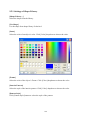
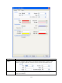
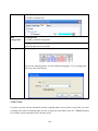
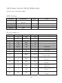
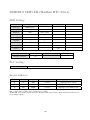
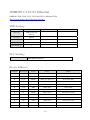
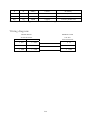
5.5 Font
Parameters in [Font] tab determine the font of no-ASCII which is used on EB8000
[Fonts for no-ascii strings]
Fonts for no-ascii strings are listed above. When users use a no-ascii font which isn’t listed on
[Fonts for no-ascii strings] table, EB8000 will select a font in the list to substitute the front
automatically.
User also can test which no-ASCII strings of Windows can be used in HMI and add them to [Fonts
for no-ascii strings] table.
65
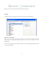
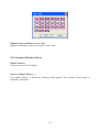
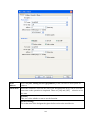
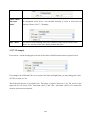
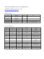
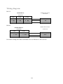
5.6 Extended Memory
Parameters in [Extended Memory] tab determine the file path of the extended memory.
Extended Memory is numbered from EM1 to EM9. Method to use in extended memory is similar
to that in other devices (i.e. Lw or RW address type). Size of each extended memory is up to 2G
word.
66
Data in extended memory is in the form of a file and stores in CF card, USB1 or USB2.The file
name of EM0~EM9 are entitled as em0.emi~em9.emi.Users can use RecipeEditor.exe to open the
file and edit the data in the extended memory.
External devices such as CF Card and USB memory stick are not affected by power loss. Data
stored in these devices is retained regardless of HMI power conditions.
If users would like to read out the data from external device when the external device is removed,
the content will be viewed as 0; if users would like to write in the data to external device when the
external device is removed, the "PLC no response" message will appear.
The HMI supports "hot swapping" of CF Card and USB devices. There is no need to interrupt
operations to change CF Card or USB devices.
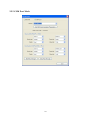
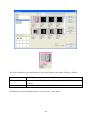
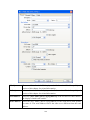
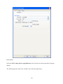
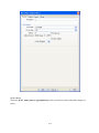
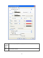
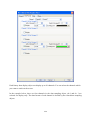
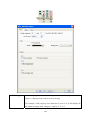
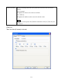
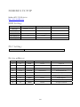
5.7 Printer Server
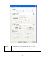
Parameters in [Printer Server] tab are to set up a MT remote printer.
67
Output settings
[Orientation]
Set the orientation of the words or pictures to be printed out.
[Printer size]
Set the paper size to be original or to fit the printer margin.
[Margin]
Set the borderline of the paper, including top, bottom, right and left.
Communication
settings
[IP address]
Assign the IP address of a remote printer via network.
[Port], [User name], [Password]
Assign the access information.
Port can be set from 1 to 65535.
Max. length of user name or password is 12 characters.
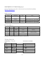
※ Please refer to the appendix Easy Printer for details.
68
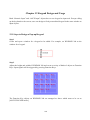
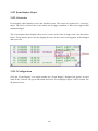
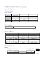
Chapter 6 Window Operations
6.1 Window Types
The basic component of a HMI screen is a Window. Users are able to configure 1997 windows or
screens. According to function and usage, there are 4 types of windows in the EB8000.
a. Base Window
b. Common Window
c. Fast Selection Window
d. System Message Window
6.1.1 Base Window
Base window is the frequently-used type of window.
Except for primary screen, it is also used on:
a. Foundation base: used as the background for other windows
b. Keyboard window
c. Pop-up window for function key object
d. Pop-up window for direct and indirect window
e. Screen saver
The illustration below shows the startup screen which uses base window.
69
6.1.2 Common Window
Window 4 is the default of common window. Objects on this window will be displayed on all of
other windows so that users always place the shared objects on the common window. When
system is in the operation, [Change common window] mode of the function key can be used to
change the source of the common window. For example, users can change the common window
from window 4 to window 20.
6.1.3 Fast Selection Window
Window 3 is defined as the Fast Selection Window. This window can coexist with base window.
Generally speaking, it is used by the frequently-used operation buttons as the picture below:
70
When using the Fast Selection Window, except to create window 3 first, uses need to set each
function of Fast Selection. The [Startup] on the picture above is the Fast Selection button which is
used to enable/disable the Fast Selection. Every setting of the Fast Selection button is in System
Parameter Settings. Please refer to the dialog below.
Except switching the attribute of the Fast Selection by Fast Selection button, system register also
provides the following addresses for uses to designate the values in the address to control Fast
Selection and Fast Selection button. Please refer to “system register” for more details.
71
[LB9013] FS window control [Enable (ON) / Disable (OFF)]
[LB9014] FS button control [Enable (ON) / Disable (OFF)]
[LB9015] FS window / button control [Enable (ON) / Disable (OFF)]
6.1.4 System Message Window
Window 5, Window 6, Window 7 and Window 8 are the defaults of system message windows.
Window 5 is the “PLC
Response” message window
When the communication between PLC and HMI
discontinues, the message window will pop up automatically
Window 6 is the message
When connection of remote HMI fails, the message window
will pop up automatically
window for “HMI
connection”
Window 7 is set for
“Password Restriction”
message window
If the user who doesn’t have enough authority to access the
object, window 7 will pop up according to the security setting
content.
Window 8 is set for “Free
Space Insufficient” message
window
When HMI built-in memory, USB memory stick or CF card
runs out of storage space, the message window will pop up
automatically.
Users can use system tag to review the free memory space of
HMI, CF card and USB device.
[LW 9072] HMI current free space (K bytes)
[LW 9074] CF current free space (K bytes)
[LW 9076] USB 1 current free space (K bytes)
[LW 9078] USB 2 current free space (K bytes)
EB8000 also provides warning message to review the memory
space insufficient.
[LB 9035] HMI free space insufficiency alarm (when ON)
[LB 9036] CF free space insufficiency alarm (when ON)
[LB 9037] USB 1 free space insufficiency alarm (when ON)
[LB 9038] USB 2 free space insufficiency alarm (when ON)
72
Note:
(1) A screen can display max. 16 pop-up windows simultaneously which include System Message
Window, Direct window and Indirect window.
(2) A window only can be display once simultaneously. It is illegal by using many direct/indirect
windows to display the same window in the base window.
(3) Windows 0~9 are for system use only while windows 10~1999 are for user operation.
6.2 Create, Delete and Set a Window
The picture below shows the window information in the EB8000. The following section introduces
how to create and set these windows.
6.2.1 Create a Window
There are two ways to create a window:
One is selecting a window number on the window tree and right click. Select [New] on the
message dialog and click OK after the completion of all settings. Please refer to the example as
below:
73
Name
The name of the window
Window no.
The number of the window, from 3 to 1999
Size
The [Width] and [Height] of the window
Frame
[Width]
The width of the frame
[Color]
The color of the frame
74
Background
[Color]
The color of the background
[Pattern]
The pattern of the background
[Pattern color]
The color of the pattern
[Filled]
The option to determine if a window is filled with the color and pattern
of the background
Underlay window
[Bottom], [Middle], [Top]
Up to three windows can be specified as underlay windows for each
base window, from [Bottom] to [Top]. The objects on the underlay
windows are displayed in order on the base window.
Popup window
[X], [Y]
Base window can also be used as pop-up window. Use [X] and [Y] to
set the location of the popup window in the base window
[Monopoly]
If the option is checked, when a base window used as a pop-up window
appears, users are not allowed to operate other windows before the base
window is closed. If a base window is used as a keyboard window,”
Monopoly “property is automatically enabled.
Another way to create a window is select [Open Window] from menu and [Open Window] dialog
appears. Please refer to the illustration below.
75
Window No., Window Name and Window Size are listed on the message table.
Click [New…] and choose window type from [Select Window Style] dialog. New window can be
created after click OK.
76
6.2.2 Window Settings
EB8000 provides two methods to modify window attributes:
a. Right click on the assigned window from window tree and select [Settings] to change the
window properties.
b. Select [Open Window] from menu and [Open Window] dialog appears. Select [Settings] to
change the window properties.
6.2.3 Open, Close and Delete a Window
To open an existing window, except double click the window No. from the window tree, users can
right click the assigned window from the window tree and choose [Open] to open the window.
Similarly, close or delete an existing window as the procedure above .Please note that the window
to be deleted has to be in close status.
77
Chapter 7 Event Log
“Event log” is used to identify the content of an event and the conditions triggering this event. In
addition, the triggered event (also called as “alarm”) and the processing procedure of the event can
be saved to the designate areas (such as HMI memory or external storage devices) in the form of
EL_yyyymmdd.evt where yyyymmdd indicates the time of the file created set by the system
automatically. For example, a file name of event, EL_20061127.evt, means the file was created on
Nov. 27th , 2006.
EB8000 also provides the following system registers to manage the event log:
[LB 9021] reset current event log (set ON)
[LB 9022] delete the oldest event log file (set ON)
[LB 9023] delete all event log files (set ON)
[LB 9024] refresh event log statistic information (set ON)
[LW 9060] total number of the event log files
[LW 9061] total size of the event log files
7.1 Event Log Management
Used with [alarm bar], [alarm display] and [event display]…etc., users are able to clearly
understand the life cycle of the whole event from happening, waiting for processing, alarm cleared.
Before using these objects, the content of an event has to be identified first.
Click the [Alarm (Event Log)] icon, and [Event Log] dialog appears as below:
78
[Category]
EB8000 provides classification feature. All events can divided into 0~255 classifications. Alarm
Bar, Alarm Display and Event Display can be assigned toe be displayed in certain the
classifications.
[Category] determines the event log catalog of current event.
The [2] of 0[2] in the above illustration demonstrates two existing identified events in the category
0.
79
[History files]
Determine the storage device of an event log. However, when users simulate the project on PC,
files will be saved on the same event log subdirectory as EasyBuilder8000.exe.
[Save to HMI memory]
Save the event log data to MT8000 memory.
[Save to CF card]
Save the event log data to CF card.
[Save to USB 1]
Save the event log data to USB disk 1. Numbering rule of USB disk is: the disk inserted to the
USB interface in the first place is numbered 1, next is numbered 2 and the last is numbered 3.
There’s no relation to the interface position.
[Save to USB 2]
Save the event log data to USB disk 2.
[Preservation limit]
After choosing the device to save the Event log, you can see the “Preservation limit” selection.
This setting determines the days of the data preserved. As below picture, the preservation time is
two days, which means HMI memory will keep the data of yesterday and the day before yesterday.
The data out of this time range will be deleted automatically to prevent the storage space from
using up.
For example, today is 7/1, the HMI will keep 6/30, 6/29 data in the memory and 6/28 will be
deleted from the memory.
80
Print
Users need to set Printer on system parameter/model, and message
will print out when alarm occurs in order.
New
Create a new event.
Delete
Delete a specific event.
Settings
Modify the definition of a specific event.
7.1.1 Excel Editing
There is an Excel icon on the up-right corner of the Alarm (Event Log) dialog for users to edit an
Event log. An editing design procedure includes: Excel Edit, Import from Excel and Export to
Excel.
81
7.1.1.1 Excel Edit
Weintek provides a standard Excel template in C:\EB8000\EventLogExample.xls for users to edit
alarm (event) log. The template includes some dropdown lists for easily usage.
Caution:
1. System tag and User-defined tag can not be set as true simultaneously. If both of them are
set as true, the system will view System tag to be true and User-defined tag to be false. If
Device type is set as User-defined tag, please set the System tag to be false.
2. The format of Color is R:G:B where and the values of R,G,B are between integer 0~255 .
3. Click Excel icon to open the EventLogExample.xls
A . Import to Event Log
Click import button to import excel file.
82
Caution:
1. When user-defined tag is set as true in the Excel, if device type can not match with the
user-defined tag, system will set false value in user-defined tag.
2. Before importing library (label library and sound library), please make sure library names exist
in the system, otherwise those library will not be imported.
B. Export to Excel
Click Export excel button to export data in an excel file.
83
7.2 Create a New Event Log
Click [New…], [Event Log] dialog appears with two tabs.
[General] tab:
84
[Category]
The category of an event.
[Priority level]
The priority of an event: According to the degrees of importance, users can choose ”Low”,
“Middle”, “High”, or “Emergency”. When the number of event log is more than max number
available in the system (the default is 1000, please refer to [General] of System Parameters to add
additional records), less important events (lower priority) will be deleted and new events will be
added in.
[Address type]
The type of address—Bit or Word mode.
85
[Scan time]
The time interval an event to be examined. System checks if an event is satisfied with the triggered
conditions via scan time.
[Delay time when power on]
The delay time an event to be examined. If be set, system delays certain time after rebooting so
that it’s able to check if an event is satisfied with the triggered condition and avoids the
unnecessary event log record.
[Read address]
By reading the read address, system obtains the value and check if an event is satisfied with the
triggered condition. Please refer to Parts/General Settings for further details.
[Notification]
When an event is triggered, the specific message is sent out from Notification address. Select [Set
ON] to send ON message out from the address. While select [Set OFF], Off message is sent out.
Please refer to Parts/General Settings for further information.
[Condition]
The trigger condition of an event. When the condition of [Address type] of an event is a “Bit”,
“ON” or “OFF” in Trigger can be selected. The illustration below shows if Trigger [On] is selected,
i.e. the status of [Read address] changes from OFF to ON, an event will be triggered and generate
an event log record (or an alarm).
When the condition of [Address type] of an event is a “Word”, several selections are available as
follows:
86
Under the condition, system will read values from [Read address] and then compare them with the
trigger conditions to decide if an event needs to be trigged. Especially if the trigger condition is set
as “==” or “<>”, [In tolerance] and [Out tolerance] need be set where [In tolerance] is used for
trigger condition and [Out tolerance] is used for system’s normal condition.
From the example, the illustration above indicates that if the value of [Read address] is bigger or
equal to 29(=30-1) or smaller or equal to 31(=30+1), the event will be triggered.
29 <= [Read address] value <=31
After the event is triggered, only when the value of [Read address] is bigger than 32( =30+2) or
smaller than 28(=30-2) will the system return to the normal condition.
[Read address] value < 28 or [Read address] value >32
Take another example above, it indicates that system is triggered when the value of [Read address]
is less then 29(=30-1) or greater then 31(=30+1).
[Read address] value <29 or [Read address] value >31
When the event is triggered, system returns to normal condition only when the value of [Read
address] is bigger or equal to 28(=30-2) and smaller than 32(=30+2).
28 <= [Read address] value <= 32
[Message] tab:
87
Text
[Content]
The text content showed on [alarm bar], [alarm display] and [event display].
Display the content of LW address of being triggered object.
Format: %#d
%: initial sign
# : LW’s address
d : end sign
For example, if the content is set as “High Temperature = %20d”, when an event is triggered, the
value of LW20 will be displayed. i.e. if the value of LW20 is 13 when an event is trigger, the
display content of the [event display] will be “High Temperature = 13”.
Except for LW, it can also show the content of Device type in Read address.
Format: $#d
$: initial sign
# : PLC’s address
d : end sign
88
For example, if Device type in Read address is MW, when message is set as “High Temperature =
$15d” and the value in MW15 is 42, the display content of the [event display] will be “High
Temperature = 42”.
[Font][Color]
Users can set Font and color for each event. The font and color of an alarm display or event
display object comes from this setting. As below illustration, these two events use different colors
and font styles.
[Write value for event display]
When an event item in an event display object is touched, the value is written to the assigned
address. Please refer to event display in [Object] chapter for more details.
[Sound]
The warning alarm can be selected when an event is triggered.
Click “Sound Library” to choose warning sound, and click “Play” to check the sound.
After the completion of each setting, a new event definition can be added as below:
89
90
Chapter 8 Data Sampling
“Data Sampling” identifies the method of data sampling, including sampling time and sampling
location. In addition, EB8000 saves the sample data to the user assigned location and in the form
of [Storage location]\[filename]\yyyymmdd.dtl where [storage location] can be HMI, CF card,
USB1 or USB2, [filename] is defined by user as a meaningful name and yyyymmdd is the built
time set by the system automatically.
EB8000 provides following system registers for data sampling management:
[LB 9025] delete the oldest data sampling file (set ON)
[LB 9026] delete all data sampling files (set ON)
[LB 9027] refresh data sampling statistic information (set ON)
[LW 9063] the number of data sampling files
[LW 9064] total size of data sampling files
8.1 Data Sampling Management
Before using Trend display or History data display to review the content of data sampling, the
method of data sampling has to be defined. Click [Data Sampling] from toolbar and then Data
Sampling Object dialog appears as below.
91
New
Add a new “data sampling” definition.
Delete
Delete a specific “data sampling”.
Settings
Modify the definition of a “data sampling”.
8.2 Create a New Data Sampling
Click [New…] and the Data Sampling Object setting dialog appears as below:
92
Read address
[Max. data records]
Max data records can be saved to a data sampling definition.
Example:
Condition
Set Max. data records as 10
without check “auto. stop”
Set Max. data records as 10 with
check “auto. stop”
Trend display – real time
The data will keep latest 10
records on the screen
Stop displaying
Data sampling
Keep recording and delete
the oldest data
Stop recording
[Data Format …]
The format of a data sampling: A data sampling may include more than one type of records.
EB8000 is able to retrieve different types of records at the same time. After clicking [Data Format],
user use “Data Format” dialog to define the content of a record.
Take the following as an example, users define three types of data: “Index” (16-bit Unsigned)、
“Pressure 1”(16-bit Signed) and “Temperature”(32-bit Float) respectively and 4 word length in
total. In other words, EB8000 retrieves the length of 4 words as a record starting from the assign
address.
Please refer to Parts—General Settings for more details.
93
Caution:
After executing off-line simulation, if users need to change data format, please delete data log file
in the C:\EB8000\datalog and then run off-line simulation again.
[PLC name]
Select the target PLC of data sampling.
[Clear address]
If the status of the assigned address is ON, obtained data will be cleared and the number of data
sampling will be set to zero.
Caution: the [clear address] is used for “real time” mode of trend display only.
[Hold address]
If the status of the assigned address is ON, sampling will be paused until the status of assigned
address returns to OFF. Please refer to Parts—General Settings for other details.
Sampling mode
EB8000 provides two methods in data sampling: “Time-based” and “Trigger-based”. If
“Time-based” mode is selected, EB8000 samples the data in a fixed frequency. Users have to set
the “sampling time interval”.
If “Trigger-based” mode is selected, users can use a status of specific address to trigger the data
sampling.
94
[Mode]
Conditions to trigger the data sampling:
“OFF → ON”
“ON → OFF”
“ON←→ OFF”
If the status of assigned address is from OFF to ON, data sampling is triggered.
If the status of assigned address is from ON to OFF, data sampling is triggered.
If the status of assigned address is changed, data sampling is triggered.
Please refer to Parts—General Settings for more details.
[Auto stop]
When the number of data sampling is equal to [Max. data records], if the Auto stop option is
selected, HMI will stop doing data sampling automatically.
1. If the data source in the [trend display] is real-time mode, the oldest record will be deleted and
new record will be added and displayed in the [trend display] object.
2. If the data source in the [trend display] is historical mode, the data keeps being sampled.
History files
Assign the storage location. But when users do the simulation on PC, data is saved to the same
subdirectory as Easy Builder 8000.exe.
[Save to HMI memory]
Save the sampling to MT8000 display.
Caution:
The data can be saved when the size of data is more than 4kb, otherwise, users need to use
LB-9034 to force the data to be stored.
[Save to CF card]
Save the sampling to CF card.
[Save to USB 1]
Save the sampling to USB stick 1. The USB stick numbering rule is: the device inserted to the
USB interface in the first place is numbered 1, next is numbered 2 and the last is numbered 3.
There’s no relation to the interface position.
[Save to USB 2]
Save the sampling to USB stick 2.
95
[Folder name]
Set the file name of the data sampling.
Preservation limit: decide the days of preservation for sampled data.
If the preservation time is two days as below, USB1 memory stick will keep the data of yesterday
and the day before yesterday.
For example, today is July 1st, the HMI will keep the data of June 30th and June 20th in the memory
but the data of June 28th will be deleted.
96
Chapter 9 Object General Properties
The contents of object’s general properties setting include:
1. Selecting the connection PLC device
2. Setting the reading and writing address
3. Using shape library and picture library
4. Setting text content
5. Adjusting profile size
9.1 Selecting the Connection PLC Device
When using some objects, select the connection PLC device is required. See the picture below,
[PLC name] is to assign the name of the connection PLC device. The picture shows that there are
two PLC devices available for selection: “Local HMI” and “Allen-Brandley DF1.” These listed
available PLC devices are sourced from “device table” in “System Parameters.”
9.1.1 Setting the Reading and Writing Address
The above picture shows that the following items are contained in reading and writing address
settings:
97
[Device type]
In selection of device types, when the connection PLC device is different, there will be different
device types for selection.
[Address]
Setting the reading and writing address.
[System tag]
Address tag includes “system tag” and “user-defined tag.” System tag, including bit address
system tag and word address system tag, is to reserve the addresses of particular purposes for the
system. When selecting “system tag,” in addition to that [Device type] will show the content of
“system tag,” [Address] will indicate the selected system tag. Refer to the picture below.
The following pictures show partial contents of bit address system tag and word address system tag
respectively, and for further information, please refer to the illustrations in the “label library”
section.
[Index register]
Refer to the illustrations in “index register” section for information on if it is necessary to select
“index register” or not.
98
The EB8000 supports the following listed numeric types. It is necessary to select the proper
numeric type, especially when using address tag.
9.2 Using Shape Library and Picture Library
Shape Library and Picture Library are used for an object to enhance its visual effect. Go to the
[New Bit Lamp Object]/ [Shape] tab to set up Shape Library and Picture Library.
99
9.2.1 Settings of Shape Library
[Shape Library…]
Select the shape from the library.
[Use Shape]
Use the shape from shape library if checked.
[Inner]
Select the color of an object’s color. Click [Color] dropdown to choose the color.
[Frame]
Select the color of the object’s Frame. Click [Color] dropdown to choose the color.
[Interior Pattern]
Select the style of the interior pattern. Click [Color] dropdown to choose the color.
[Pattern Style]
Click [Pattern Style] button to select the style of the pattern.
100
[Duplicate these attributes to every state]
Duplicate all attributes of the current state to other states.
9.2.2 Settings of Picture Library
[Picture Library]
Select the picture from the library.
How to set [Shape Library…]
Click [Shape Library…] button, the following dialog appears. The currently selected shape is
marked by a red frame.
101
The above illustration gives information of one of the Shapes in the Shape Library as follows:
0: Untitled
The Shape’s name and number in the library.
State no.: 2
The number of the Shape’s states. In this case, it shows the Shape possesses
two states.
Frame
Indicate that the Shape is set with “frame” only.
The Shape below shows that the Shape is set with “inner” and “frame.”
102
Note: Refer to the illustrations in the “Setting-up and using Shape Library and Picture Library”
section for the details about all of the settings in the “Shape Library’s setting dialog box.”
Click [OK] and preview the design of the shape after the complication of the settings.
How to set [Picture Library…]
Click [Picture Library…] button and picture library dialog appears. The currently selected picture
is marked by a “red” frame.
103
The above illustration gives information of one of the Picture in the Picture Library as follows:
Picture name 0 : PB Red The name of the Picture
Total states
2
The number of the Picture states
Image size
30054
The size of the Picture
Image format BMP
The format of the Picture; BMP means bitmap Picture and its
format can be JPG or GIF.
104
Refer to the illustrations in the “Setting-up and using Shape Library and Picture Library” section
for the details about all of the settings in the “Picture Library’s setting dialog box.”
Click [OK] and preview the design of the picture after the complication of the settings.
9.3 Setting Text Content
Go to the [New Bit Lamp Object]/ [Label] tab to set the text content of the object.
105
[Use label]
Check [Use label] and click [Label Library] button to add and edit the text. The EB8000 supports
Windows true-font.
[Use label library]
Check [Use label library] and Label tag dropdown whose resource comes from label library
appears.
[Label Library…]
Refer to the illustrations in the “Setting-up and using Text and Label Library” section to view the
usage of label library.
106
[Font]
Select font style in font list.
[Color]
Select the font color for the text.
[Size]
Select the font size for the text. The EB8000 supports all the text sizes.
[Align]
Select the alignment method of the text for multiple lines.
The picture below shows how the text to be aligned when “Left” in [Align] is set.
The picture below shows how the text to be aligned when “Center” in [Align] is set.
The picture below shows how the text to be aligned when “Right” in [Align] is set.
[Blink]
Select the blink feature of the text:
Choose [None] to disable the feature or choose blinking period as “1 second” or “0.5 seconds”.
107
[Italic]
Use Italic font.
[Underline]
Use Underline font.
[Movement] setting
[Direction]
Set the direction of the movement of the marquee effect.
Two options for the marquee to be displayed:
[Continuous]
When [Continuous] isn’t be checked, the next text appears only after the previous text disappears
completely. See the picture below.
When [Continuous] is selected, the text will be displayed continuously.
108
[Speed]
Set the speed of the text movement.
[Content]
Set the content of the text. If using the Label Library, the content will be sourced from the Label
Library.
[Duplicate this label to other states]
This function is used to duplicate the current text content to the other states.
[Tracking]
When [Tracking] is selected, moving the text of one state will also move the text of other states.
9.3.1 Adjusting Profile Size
When a bit lamp is created, double click the object. Go to the [Bit Lamp Object’s properties] /
[Profile] tab to adjust the position and size of the object.
a. Position
Pin the position and size of the object. When checked, the position and size of the object will not
be able to be changed.X and Y mean the [X] and [Y] coordinate of the top left-hand corner of the
object.
b. Size
Adjust the width and height of the object.
109
9.4 Station Number’s Variable
EB8000 V1.31 or above provides variable settings in PLC station number.
As below picture, the var2 is one of 16 station number variables.
The syntax of Station number’s variable:
varN#address
The range of N is the integer from 0~15; address is PLC’s address.
Examples:
var5#234 (var5 is station number, 234 is PLC’s address)
var15#456 (var15 is station number, 456 is PLC’s address)
16 station numbers are availble : var0 ~ var15. The station variables read values from
LW10000~LW10015. The list below is variable and its corresponding system reserved address
LW:
var0
var1
var2
var3
var4
var5
LW10000
LW10001
LW10002
LW10003
LW10004
LW10005
var6
var7
var8
var9
var10
var11
var12
var13
LW10006
LW10007
LW10008
LW10009
LW10010
LW10011
LW10012
LW10013
110
var14
var15
LW10014
LW10015
For example, var0 reads value from LW10000, when LW10000 is 32, var0#234 = 32#234 (the
station number is 32); similarly, var13 reads value from LW10013, when LW10013 is 5,
var13#234 = 5#234。
9.4.1 Broadcast Station No.
MT6000/8000 provides two ways for users to use broadcast command. First one is to directly set
the broadcast in EB8000/Edit/System parameters/Device as below:
Second one is to use system tag to enable or disable broadcast station no and change broadcast
station no. Corresponding system tag is listed as below:
LB9065
LB9066
LB9067
disable/enable COM 1 broadcast station no.
disable/enable COM 2 broadcast station no.
disable/enable COM 3 broadcast station no.
LW9565
LW9566
LW9567
COM 1 broadcast station no.
COM 2 broadcast station no.
COM 3 broadcast station no.
111
Chapter 10 Security
EB8000 security includes two parts:
1. User security and whose operable classes
2. Object’s Security
10.1 Settings of Password and Classes
Go to [Edit]/ [System Parameter Settings]/ [Security] to set user security. There are seven levels of
user security, including “none”, and “A~F”. Password are Digital only (0-9) and up to 12 sets of
user password available.
112
After the password is entered, the operable objects for the user are decided by security setting. For
example, the security setting of user 1 is as below. That’s means the user is permitted to operate
the objects with security level of “None”, and A, C, E.
In addition to inputting the passwords to the system reserved register [LW9220: password], which
is a double words value (32 bits), a correct process of password setting requires users to appoint
the users by using [LW9219], single word value (16 bits) where digit 1~12 represents User 1 ~
User 12 respectively.
113
If the password is wrong, [LB 9060: password error] state will be set to ON; if password is correct,
[LB 9060] is set to OFF.
The passwords of from user1 to user 12 can be obtained from system reserved registers [LW9500]
to [LW 9522], 24 words in total.
Users can change passwords even when the HMI is in operation. By the system reserved register
[LB9061: update password (set ON)], when its state is switched from OFF to ON, the EB8000 will
use the data saved in the system reserved registers from [LW9500] to [LW9522] to update the
password table and create the new passwords.
Note: The user operable class won’t be changed due to the change of password.
When the state of [LB9050] (user logout) is changed from ON to OFF, current users will be forced
to log out the system. At this time, only the object defined as “None” class can be operated.
[LW9222: classes can be operated for current user] records the operable class for current users:
bit0 = 1 means the operable object for current users is class A; bit1=1 means the operable object
for current users is class B and so on.
10.2 Object’s Security
114
Safety control
“Safety control” is mainly used to prevent operator from mis-operating an
object accidentally. There are two methods for protection:
[Min. press time (sec)]
Only continuous pressing time no less than this value can an object be
activated successfully.
[Display confirmation request]
After pressing the object, a confirm dialog will appear. Users need to click
“Yes” to make sure the operation execution. If response to confirm dialog
longer than the value of [Max. waiting time (sec)], the dialog will disappear
automatically and cancel the operation.
115
Message text ( “Please confirm the operation.” ) in the window is defined in
[System Message]. Text can be changed from [System Message] dialog.
Click System Message icon from tool bar and then System Message dialog
appears where the first part is set for the content of operation confirmation.
Interlock
When the feature is applied to an object, whether or not an object is allowed
to be operated is decided by the state of appointed bit address (or called
“Enable” address). ”Enable” address must be in the form of Bit address. The
content of the address is set in the following dialog.
116
Fox example, supposed “Use interlock function” is checked and the “Enable”
bit address is set to [LB0].The object can be operated only when the state of
[LB0] is ON. The “Interlock” feature also provides the following settings.
[Use interlock function]
Enable/disable the interlock function.
[Hide when disabled]
When the state of [interlock] function is OFF, hide the object.
User
restriction
This function is used to set the object’s security: define the users permitted to
operate the object. When “Operator class” is selected as ”None”, the object
operation is open to the users with all security levels. The following settings
are also provided in the function:
[Disable protection permanently after initial activation]
Once the operator’s operation class has ever conformed to the security of the
object, the system permanently stop checking the security of the object. Even
if the security level of the users is changed will not affect the operation of the
object.
[Display warning message if access denied]
When the user’s current security level does not conform to the security level
of the object, a warning dialog appears.
117
Window 7 is set as an alert message for authority security. Users can design
the content of the message.
[Make invisible while protected]
When a user’s security level does not conform to the security level of the
object, the object will be hidden.
10.3 Example of Security
The following is an example to illustrate the steps of security feature:
Step1: First of all, create a new project. Go to System parameter/Security, add three users and set
different passwords and classes.
User 1 can operate objects with class A, user 2 can operate objects with class A and B, and user 3
can operate objects with class A, B, and C.
Step2: Set objects in Window_10 as below:
118
[NE_0] and [NE_1] are numeric input objects where address are [LW9219] and [LW9220:
password] for inputting user ID and password. [LW9219] is for entering user ID (1~12), with the
length of 1 word, in the form of 16-bit Unsigned as below.
[LW9220] is for entering user password with the length of 2 words, in the form of 32-bit Unsigned
as below.
119
[ND_0] is numeric display object with address [LW9222: classes can be operated for current user]
to indicate user’s state. The data is in the form of 16-bit Binary.
[SB_0]~[SB_2] are Set Bit objects which are set with different classes but selected “Make
invisible while protected“. i.e. [SB_0] is class A, [SB_1] is class B, [SB_2] is class C. The setting
of [SB_0] object:
The Set Bit object (SB_3, LB9050: user logout) is for user logout as below:
120
Step 3: After complete the design and settings of the objects, save, compile and do the off-line
simulation for the project. The illustration as below is initial screen of off-line simulation.
At this time, no password is entered.
[LW9222] shown “0000000000000000” means current user only can use object with “none”
class. Moreover, [SB_0]~[SB_2] are the objects with the security levels of class A~ class C and at
the same time “Make invisible while protected“ is selected, therefore, [SB_0]~[SB_2] objects are
hidden by the system.
Step 4: When the user enters the password “111”, the screen will become:
121
The user 1 is permitted to use object with class A. Consequently, [SB_0] appears and allows user
to operate. Now, bit 0 in [LW9222] becomes 1.
Step 5: Next, when the user enters the user 3’s password (333), t the screen will become:
The user 3 is permitted to use object with class A,B,C. Now, bit 0 ~ bit 3 in [LW9222] become 1
to confirm the current user is allowed to use objects with class A,B,C.
Step 6: At this time, if [LB9050] is pressed and force current user to logout, the system will return
to initial state. In other words, current user only can use object with “none” class.
122
123
Chapter 11 Index Register
11.1 Introduction
The EB8000 provides 32 index registers for users to use addresses more flexible. Via index
register, users can update object’s read / write address without changing content of the object
under the machine in operation.
The addresses of the 32 index registers are as follows:
INDEX 0
……
……
INDEX 15
INDEX 16
……
……
INDEX 31
[LW9200] (16-bit)
[LW9215] (16-bit)
[LW9230] (32-bit)
[LW9260] (32-bit)
INDEX 0 ~ INDEX 15 are 16-bit registers with the range up to 65536 words; INDEX 16 ~ INDEX
31 are 32-bit register with the range up to 4G words.
11.2 Example of Index Register
Here is an example to describe how to use the index registers.
The “Read address” will be [LW100] when [Index register] is not checked.
124
But in the illustration below, the “Read address” becomes [LW (100 + Index 3)] when [Index
register] is checked. “Index 3” represents the value at INDEX 3: LW9203 (16bit) ; in other words,
if the value at the [LW9203] is 5, the “Read address” in the becomes [LW105], i.e. [LW100+5].
By using index registers, users can change object’s reading and writing addresses in operation
without changing the object’s content. For example as below, set Index 3 as 0, i.e. the value at the
[LW9203] address is 0. Under this situation, the contents of [LW100 + Index 3] and [LW101 +
Index 3] are the same as those of the [LW100] and [LW101].
At this time, the setting of Object A’s “Read address” is:
125
The setting of Object B’s “Read address” is:
The setting of Object C’s “Read address” is:
Now, if the user changes Index 3 value to 20, the contents of [LW100 + Index 3] and [LW101 +
Index 3] will become those of [LW120] and [LW121], i.e. the values in [LW100+20=LW120] and
[LW101+20=LW121].
Similarly, the index register can also work with LB.
1 word = 16 bit, 1 value change of index register means the change of 16 bits.
126
See the example below. When Index 5 is set as 0, the contents of “Bit Lamp” of [LB0] and [LB6]
are the same as those of “Toggle Switch” of [LB0+Index 5] and [LB6+Index 5]
Now, if users change Index 5 value to 1, and then the contents of Toggle Switch are the same as
those of [LB16] and [LB22], i.e.[LB0+16=LB16] and [LB6+16=LB22].
127
Chapter 12 Keypad Design and Usage
Both “Numeric Input” and “ASCII Input” objects have to use keypad as input tool. Except calling
up the keyboard to the screen, users can design a fixed personalized keypad in the same window as
input objects.
12.1 Steps to Design a Pop-up Keypad
Step 1
Create and open a window for a keypad to be added. For example, set WINDOW 200 as the
window for a keypad.
Step 2
Adjust the height and width of WINDOW 200 and create a variety of kinds of objects as Function
Keys. Input signals will be triggered by pressing Function Keys.
The Function Key objects on WINDOW 200 are arranged as above which must to be set as
[ASCII/UNICODE mode].
128
Where FK_11 is used as the “Escape (Esc)” key and its setting is:
FK_14 is used as the “ENTER” key and its setting is:
Most of the other Function Keys are used as number or text inputs. For example, FK_0 is used to
trigger signal of input number “1” and its setting is:
At last, select a suitable Picture for each Function Key object. GP_0 is a “picture” object where is
place at the lowest layer as the background.
Step 3
Go to [General] tab in “System Parameter Settings” and click [Add…] in [Keyboard]. [Add a
keyboard] dialog appears. Select WINDOW 200 and press “OK”.
129
As illustration shown as below, a new item: “200.Keyboard” will be added to [Keyboard] in
[General] tab in “System Parameter Settings.”
After a Keypad object is created, when open the object of “Numeric Input” or “ASCII Input”,
“200.Keyboard” can be found in [Keyboard] setting tab, as shown below. [Popup Position] is used
to decide the display position of the Keypad in a screen where EB8000 divides the screen into 9
areas.
130
Selecting “200.Keyboard,” when users press “Numeric Input” or “ASCII Input” object. WINDOW
200 will pop up on the HMI screen.
12.2 Steps to Use Keypad without Title Bar
Step 1
Create a Direct window. Set a read address to activate a direct window (ex: LB0).In
[General]/[Attribute], select “No title bar” and Window no.
131
Step 2
Set WINDOW 200 the same size as keypad.
Step 3
Create a Numeric Input object, select “Use an external keyboard”.
132
Step 4
Add a Set Bit object, set the LB 0 as ON and overlay it on the Numeric Input object. If the user
does not want to use the keypad, set LB0 as OFF to disable the feature.
133
12.3 Steps to Use Fixed Keypad
Users can also place a fixed keypad in the same window as input objects. In this way, keypad can’t
be moved or disable.
Step 1
Create a Numeric Input object, and select [Use an external keyboard].
134
Step 2
Design a keyboard by function keys and place it on the screen.
Step 3
Design the keypad by function key objects and place the keypad on the window.
135
136
Chapter 13 Object
This chapter is to illustrate the ways of using and setting all kinds of objects. For those settings
generic for all the objects, such as index register, label, shape, and so on, please refer to the chapter
“Object’s General Attributes”.
13.1 Bit Lamp Object
13.1.1 Overview
Bit Lamp object displays the ON and OFF states of a bit address. If the bit state is OFF, the State 0
shape will be displayed. If the bit state is ON, the State 1 shape will be displayed
13.1.2 Configuration
Click the “bit lamp” icon on the toolbar and the “Bit Lamp Object’s Properties” dialogue box will
appear, fill in the content of dialogue box and press OK button, a new bit lamp object will be
created. See the pictures below.
137
Description
A reference name that assigned with the object, the system does not take use of
this reference name, it is for user document only.
Read address
Select the [PLC name] [device type][address] of the bit device that controls the
bit lamp object.
[Invert signal]
Display shape with inverse states; for example, the present state is “OFF”, but it
displays the shape of “ON” state.
Blinking
Set blinking attribute of bit lamp.
Blinking time
Set the frequency of blinking
138
Blinking mode
None
No blinking.
Alternating image
on state 0
Alternatively display the shape of state 0 and state 1 when the bit value is OFF
(state 0)
Alternating image
on state 1
Alternatively display the shape of state 0 and state 1 when the bit value is ON
(state 1)
Blinking
on state 0
Display the shape of state 0 in blinking when the bit value is OFF (state 0).
Blinking
on state 1
Display the shape of state 1 in blinking when the bit value is ON (state 1).
139
13.2 Word Lamp Object
13.2.1 Overview
A Word Lamp object displays the corresponding shape according to the value in the designated
word address. (up to maximum of 256 states)
13.2.2 Configuration
Click the “Word lamp” icon on the toolbar and the “Word Lamp Object’s Properties” dialogue box
will appear, fill in each items and press OK button, a new word lamp object will be created. See
the pictures below.
140
Description
A reference name that assigned with the object, the system does not take use of this
reference name, it is for user document only.
Mode and Offset
Word lamp object offers the following three modes of selection:
a. “Value”
display mode
Calculate result of word value to subtract [offset] and displays its corresponding
shape.
141
In the above setting, if the value of [LW200] is 5, the shape of sate 2 is displayed. See
the picture below.
b. “LSB” display
mode
c. “Change state
by time” display
mode
Transfer the word value to binary, the lowest bit other than value 0 designate the
current state. Please refer to the following table for illustration.
Decimal System
Binary System
Mapping State
0
0000
All bits are 0, display the shape of
state 0
1
0001
The lowest bit other than 0 is bit 0,
display the shape of state 1
2
0010
The lowest bit other than 0 is bit 1,
display the shape of state 2
3
0011
The lowest bit other than 0 is bit 0,
display the shape of state 1
4
0100
The lowest bit other than 0 is bit 2,
display the shape of state 3
7
0111
The lowest bit other than 0 is bit 0,
display the shape of state 1
8
1000
The lowest bit other than 0 is bit 3,
display the shape of state 4
The states of the object have nothing to do with the word value. The system display
different shape of states in according to time frequency.
142
Read address
Select the [PLC name] [device type][address] of the word device that controls the
word lamp object.
Attribute
No. of states
The number of the object’s states. The state number begins from 0 to [no. of States] 1. Supposed that the number of the states is 8, the valid states will be 0, 1, 2,…, 7.
When the word value is more than [no. of states] - 1, the system will display the shape
of last state.
13.2.3 Restrictions
In label dialog, Language 1 is able to change attribute settings, for Language 2~8 only font size
can be changed and other settings follows language 1.
143
13.3 Set Bit Object
13.3.1 Overview
The Set Bit object provides two operation modes: the “manual operation” mode defines a touch
area, users can activate the touch area to set the state of the bit device to be ON or OFF. When
users select the “automatic operation” mode, the operation will be automatically activated in
pre-configured conditions, the touch area is no action at any circumstance.
13.3.2 Configuration
Click the “Set Bit” icon in the toolbar and the “New Set Bit Object” dialogue box will appear, fill
in each items and press OK button, a new Set Bit object will be created. See the pictures below.
144
Description
A reference name that assigned with the object, the system does not take use of
this reference name, it is for user document only.
Write address
Select the [PLC name] [device type][address] of the bit device that system set
value to .
Write after
button is
released
If this function is selected, the operation is activated at touch up. If the function is
not selected, the operation is activated at touch down. If the “Momentary” switch
is selected as the operation mode, the [Write after button is released] function will
be ignored.
Attribute
Set Style
Please refer to the following description for different type of operation mode.
145
Macro
Set ON
When the operation is activated, the bit device will
be set to ON.
Set OFF
When the operation is activated, the bit device will
be set to OFF.
Toggle
When the operation is activated, the bit device will
be set to opposite.
Momentary
When touch down the area, the bit device will be
set to ON, when touch up the bit device will be set
to OFF.
Periodical toggle
The state of the bit device will be switched
between ON and OFF periodically. Operation’s
time interval can be selected in the combo box
showed in the picture below:
Set ON when window
open
When the window containing the Set Bit object is
opened, the bit device will be automatically set to
ON.
Set OFF when window
open
When the window containing the Set Bit object is
opened, the bit device will be automatically set to
OFF.
Set ON when window
close
When the window containing the Set Bit object is
closed, the bit device will be automatically set to
ON.
Set OFF when window
close
When the window containing the Set Bit object is
closed, the bit device will be automatically set to
OFF.
Set ON when backlight
on
When the backlight is turned on, the bit device is
automatically set ON.
Set OFF when backlight
on
When the backlight is turned on, the bit device is
automatically set OFF.
Set ON when backlight
off
When the backlight is turned off, the bit device is
automatically set ON.
Set OFF when backlight
off
When the backlight is turned off, the bit device is
automatically set OFF.
Users can use set bit object to activate macro commands. Macro commands have
146
to be built before configure this function. Please refer to related chapter on how to
edit Macros.
Set style
When “Set style” is selected as “Toggle”, there are three different modes to trig
macro command, i.e. OFF->ON, ON->OFF or ON<->OFF.
147
13.4 Set Word Object
13.4.1 Overview
The Set Word object provides two operation modes: the “manual operation” mode and the
“automatic operation” mode. The “manual operation” mode defines a touch area, and users can
activate the area to set the value of the word device. When users select the “automatic operation”
mode, the operation will be automatically activated in pre-configured conditions, the touch area is
no action at any circumstance.
13.4.2 Configuration
Click the “Set Word” icon on the toolbar and the “New Set Word Object” dialogue box will appear,
fill in each items and press OK button, a new Set Word object will be created. See the pictures
below.
148
Write address
Select the [PLC name] [device type][address] of the word device that system set
value to .
[Write after
button is
released]
If this function is selected, the operation is activated at touch up. If the function is
not selected, the operation is activated at touch down.
Notification
When this function is selected, in the “manual operation” mode, the state of the
designated bit device will be set to [ON] or [OFF] at the same time that the
operation is completed.
[Enable]
Click to select notification function.
149
[Before
writing]
To set the state of the designated bit device before write to word device
[After
writing]
To set the state of the designated bit device after write to word device
Attribute
[Set style]
To set the operation mode. The available modes for selection are listed as follows:
a. “Write constant value”
Set constant function. When the operation is activated, the [Set value] will be
written into the word device. The constant’s format (16-bit BCD, 32-bit BCD, …)
depends on the format of “Write address”.
“Increment value (JOG+)”
Increase value function. When the operation is activated, the [Inc. value] will be
added to the value of the word device, on the condition that the result is not larger
than the value [Upper limit].
b. “Decrement Value (JOG-)”
Decrease value function. When the operation is activated, the [Dec. value] will be
subtracted from the value of the word device, on the condition that the result is not
less than the value [Bottom limit].
150
c. “Press and hold increment (JOG++)”
Press and hold increment function. When the touch down is held longer than the
time set in [JOG delay], the value of the word device will be added by the value set
in [Inc. value] at the speed set in [JOG speed], on the condition that the result is not
larger than the value in [Upper limit].
e. “Press and hold increment (JOG--)”
Press and hold decrement function. When the touch down is held longer than the
time set in [JOG delay], the value of the word device will be subtracted by the value
set in [Dec. value] at the speed set in [JOG speed], on the condition that the result is
not smaller than the value in [Bottom limit].
f. “Periodical JOG++”
Periodically increment function. A set word object can use the interval set in [Break
time] and the value set in [Inc. value] to automatically increase the value of the
word device, on the condition that the result is not larger than the value in [Upper
limit].
151
g. “Automatic JOG--”
Periodically decrement function. A set word object can use the interval set in [Break
time] and the value set in [Dec. value] to automatically increase the value of the
word device, on the condition that the result is not smaller than the value in [Bottom
limit].
h. “Periodical bounce”
Periodically bouncing function. A Set word object will add the value set in [Inc.
value] to the value of the word device at the regular intervals set in [Break time]
until the resulting value reaches the value in the [Upper limit], and then subtract the
value set in [Inc. value] from the value of the word device at the same intervals until
the result value reaches the value in the [Bottom limit]. In the example shown
below, the value in the word device will change periodically in order of 0, 1, 2.., 9,
10, 9, 8, 7,…, 1, 0, 1, 2……
i. “Periodical step up”
Stepping up function. A Set word object will add the value set in [Inc. value] to the
value of the word device at the regular intervals set in [Break time] until the result
value reaches the value in the [Upper limit], and the value of the word device will
return to the value of the [Bottom value] and then repeat the action to keep the value
152
in an active state. In the example shown below, the value of the word device will
change periodically in order of 0, 1, 2,…, 9, 10, 0, 1, 2, ……
j. “Periodical step down”
Stepping down function. A Set word object will subtract the value set in [Dec.
value] from the value of the word device at the regular intervals set in [Break time]
until the result value reaches the value of the [Bottom limit], and the value of the
word device will return to the value of the [Upper value] and then repeat the action
to keep the value in an active state. In the example shown below, the value of the
word device will change periodically in order of 10, 9, 8,…, 1, 0, 10, 9, 8, ……
k. “Set when window open”
When the window containing the object is opened, the value of [Set value] will be
automatically written into the word device.
l. “Set when window close”
When the window containing the object is closed, the value of [Set value] will be
automatically written into the word device .
153
m. ”Set when backlight on”
When the backlight is turned from off to on, the value of [Set value] will be
automatically written into the word device.
n. “Set when backlight off”
When the backlight is turned from on to off, the value of [Set value] will be
automatically written into the word device.
154
13.5 Function Key Object
13.5.1 Overview
Function key object is used to change base window, pop-up window and close windows. It can
also be used to design the keypad buttons.
13.5.2 Configuration
Click the “Function Key” icon on the toolbar and the “Function Key Object’s Properties” dialogue
box will appear, fill in each items and press the OK button, a new function key object will be
created. See the pictures below.
155
Function Key object provides the following operation modes:
[Active after
button is
released]
If this function is selected, the operation is activated at touch up. If the function is not
selected, the operation is activated at touch down.
[Change
full-screen
Window]
Change base window.
[Change
Common
Change common window; refer to the “windows” chapter for related information.
NOTE: Do not use this function to pop up the window which has been opened by
direct / indirect window object.
156
Window]
[Display Popup Pop up window. The pop up window must be on the top of the base window. There is
a [Close when change window] option with this function, see the picture below; when
Window]
the function is selected, the pop up window will be closed when executing change
base window. Otherwise, users have to set a “Close” button on the pop-up window to
close the window.
[Window no.]
This is used to select the window no. when performing “change base window”,
“change common window”, and “pop up the window”
[Return to
Previous
Window]
This is used to return to the previous base window. Fox example, when changing
window 10 to window 20, users can use this function to return to window 10. This
function is only available for base window change.
[Close window] Close the pop-up windows on the top of the base window.
Items in ASCII
mode
[ASCII mode] is used as element to configure a keypad, the keypad is used where
numbers or texts are needed to input to the numeric input object or ASCII input
object. Refer to the “Designing and Using Keypad” chapter for detailed information.
[Enter]
Same as the keyboard’s “enter” function.
[Backspace]
Same as the keyboard’s “backspace” function.
[Clear]
To clear the temperate input alphanumeric strings stored in the buffer.
[Esc]
Same as the [Close window] function, it is used to close the keyboard window.
[ASCII]
To set the characters that are input in the numeric input object and the ASCII input
object. Digital characters such as 0,1,2… or ASCII characters like a,b,c,… etc. are
available for selection.
[Execute Macro]
157
Macro commands are executed with this selection. Macro commands have to be built
before users choose this function. Please refer to related chapter on how to edit
Macros.
[Screen hard copy]
Hardcopy current display screen to the printer attached with MT8000. Before using
this function, please choose printer model in System Parameter / Model / printer. If
printer does not support color, user can select grayscale to have a better printout
effect. Black and white is for improving text printing quality.
Notification
[Enable]
When the function is selected, the MT8000 will set the state of the designated bit
device to [ON] or [OFF] after the action is completed.
13.5.3 Non-ASCII character input
Below we illustrate the method to input non-ascii character such as Traditional Chinese, Simplified
Chinese, Japanese, Greece and so on.
Step1: Setting non-ascii fonts
Go to System parameter/Font and add non-ascii fonts in the “Fonts for non-ascii strings” list. For
example, use “AR MinchoL JIS” for Japanese, ” AR MingtiM GB” for simplified Chinese, ” AR
MingtiM KSC” for Korean, ” Arial” for Greek, please refer illustration below.
158
Step2: Design non-ascii input keypad
Create “window11” for non-ascii input keypad, keypad design is shown below.
Those object on the window are function keys with input code in accord with the label . For
example, to input ”简” function key, create a function key object/General/[ASCII]/[UNICODE]
mode, type in ”简” in the column as below illustration.
159
Go to Function key/Label and then select “Use label”, type ”简” in the content and in the
Attribute/Font select ” AR MingtiM GB”, it must be the same as setp1’s setting, as illustrated
below.
The label of non-ascii function key must use the same Font. For example, in simplified Chinese
keypad, the fonts all use ” AR MingtiM GB”.
After complete the keypad configuration, add window11 into System Parameters / General /
keyboard as illustration below.
160
161
13.6 Toggle Switch Object
13.6.1 Overview
Toggle Switch object is a combination of bit lamp object and set bit object. The object can be used
not only to display the state of a bit device but also to define a touch area, when activated, the state
of the bit device will be set to “ON” or “OFF”.
13.6.2 Configuration
Click the “Toggle Switch” icon on the toolbar and the “New Toggle Switch Object” dialogue box
appear, fill in each item, and press OK button, a new toggle switch object will be created. See the
pictures below.
162
Read address
Select the [PLC name] [device type][address] of the bit device that control the
display of toggle switch state.
Write address
Select the [PLC name] [device type][address] of the bit device that system set
value to. The write address can be the same as or different from the read
address
[Write when button is released]
Refer to the “Set Bit Object” section of this chapter for related information.
Attribute
This is used to select the operation mode. The available operation modes for
163
selection include “Set ON”, “Set OFF”, ”Toggle”, and ”Momentary”. Refer to
the illustrations in the “Set Bit Object” section of this chapter for related
information.
Macro
Commands
Users can execute macro command by trigging toggle switch. This function is
the same as that of set bit object. Please refer to “the chapter of set bit object”.
164
13.7 Multi-Switch Object
13.7.1 Overview
Multi-State Switch object is a combination of word lamp object and set word object. The object
can be used not only to display the state of a word device but also to define a touch area, when
activated the value of the word device can be set.
13.7.2 Configuration
Click the “Multi-State Switch” icon on the toolbar and the “New Multi-State Switch Object”
dialogue box will appear, fill in each item, then click OK button, a new Multi-State Switch object
will be created. See the pictures below.
165
[Mode]
There are “Value” and “LSB” display mode. Refer to the “Word Lamp Object”
section of this chapter for related information.
[Offset]
It is used in the “Value” display mode. Refer to the “Word Lamp Object”
section of this chapter for related information.
Read address
Select the [PLC name] [device type][address] of the word device that controls
the display of multi-state switch..
Write address
Select the [PLC name] [device type][address] of the word device that system
set value to. The write address can be the same as or different from the read
address.
166
[Write when button is released]
Refer to the “Set Bit Object” section of this chapter for related information.
Attribute
Select the object’s operation mode.
[Switch style]
There are “JOG+” and “JOG-” for selection. When the read address is the same
as the write address, the minimum value of the word value is [Offset] (state 0),
and the maximum value is “[no. of state] -1 + [Offset]”. See the picture below.
a. “JOG+”
When the Multi-State Switch object is activated, the value of the write address
will be added by 1. In the “Value” display mode, if the resulting value is equal
to or larger than the value of [No. of States] + [Offset] and “Enable” in [Cyclic]
is selected, the value of the write address will return to [Offset] and show the
state 0; otherwise the value of the write address will maintain as ([No. of
states] – 1) + [Offset] and shows the state ([No. of states no.] – 1).
NOTE: Like the word lamp object, the state shown by Multi-State Switch
object is the value of the word device subtracts [Offset].
b. “JOG-”
When the Multi-State Switch object is activated, the value of the write address
will be subtracted by 1. In the “Value” display mode, if the resulting value is
smaller than the value of [Offset] and “Enable” in [Cyclic] is selected, the value
of the register will change to ([No. of states] – 1) + [Offset] and shows the state
([No. of states no.] – 1); otherwise the value of the word device will remain in
[Offset] and shows the state 0.
167
13.8 Slide Object
13.8.1 Overview
The slide object can be used to display the value of word device.
13.8.2 Configuration
Click the “slide object” icon on the toolbar and the dialogue box will appear, fill in each items and
click OK button, a new slide object will be created. See the picture below.
168
Write
address
Select the [PLC name] [device type][address] of the word device that system set
value to
Notification
When this function is selected, the state of the designated bit device can be set at the
same time as the operation is completed. There are [ON] and [OFF] selection to set
the state.
[Enable]
This is to select whether or not to use the function.
[Before writing]
To set the state of the designated register before write to the word device.
169
[After writing]
To set the state of the designated register after write to the word device.
Attribute
[Direction:]
The bar on the slide direction, i.e. left, right, up and down.
170
[Resolution:]
The slider will move in every [N] lines step, where [N] is the
resolution.
For example,
if [N] = 10, every 10th line will be displayed
if [N] = 5, every 5th line will be displayed
if [N] = 1, every line will be displayed
[Low limit & High limit: ]
a. Constant
The low limit and high limit of the word device is set as constant
value. i.e. [Input low] and [Input high]
b. Address
The low / high limit of the word device is controlled by an designated
address.
Control address
Low Limit
High Limit
16-bit format
Address+0
Address+1
32-bit format
Address+0
Address+2
[Coarse increment:]
If this option is selected, the word value will increase/decrease one
[increment] value for every touch activation. If not, the word value will
be set the value in accord with the touch activated point.
171
Moving piece
There are four moving piece for selection. You also can adjust the
width of moving piece.
Frame/Background/Slot
This is use to select slide object frame, background and slot’s color.
172
13.9 Numeric Input and Numeric Display Objects
13.9.1 Overview
Both of the Numeric Input object and the numeric display object can be used to display the value
of the word devices. The difference is the numeric input object can be used to input data from the
keypad, the input value is written to the designated word devices.
13.9.2 Configuration
Click the “numeric input” or “numeric display” icon on the toolbar and the “New Numeric Input
Object” or “New Numeric Display Object” dialogue box will appear, fill in each items, click OK
button and a new “Numeric Input Object” or “Numeric Display Object” will be created. See the
pictures below.
The difference between the “New Numeric Input Object” and “New Numeric Display Object”
dialogue boxes is that the latter has the settings for ”Notification” and keypad input while the
former doesn’t have. The picture below shows the [General] tab in “New Numeric Display
Object.”
173
Read
address
Select the [PLC name] [device type][address] of the word device that system
display its value and write new data to it.
Notification
When this function is selected, the state of the designated bit device will be set to
[ON] or [OFF] after the value of the register is changed successfully.
[Enable]
Click to enable notification function.
[Before writing]
To set the state of the designated bit device before update the word device..
[After writing]
174
To set the state of the designated bit device after update the word device.
Input Order
When user input value into “Numeric input” or “ASCII input” and then press ENT,
the system will automatically search next active Numeric or ASCII input object.
[Input Order]
a. Check Input order
[Numeric input] has a [Input order] and [Group], click “Enable” to active this
function. In the [Input order], input the sequence number for each input object, and
the system will follow this order to the next object.
b. Check Group
User can define separate input objects to different group. The system will only search
the next object in the same group.
c. In online operation, please click ES button to stop the system searhing for the
NI object.
175
NOTE :If one of input object has set “interlock” function, this object will be skip in
the “next input object search”.
z [Input order] range from 1 to 511
[Group] range from 1 to 15
Keyboard
There are two ways to display keyboard, one is to use system parameter/ General/
keyboard, to include standard keyboard into the project. The another is to select
“external keyboard” and use direct window to display customized keyboard. The
customized keyboard is composed of function key.
When using the Numeric Input Object, you may select the keypad style. Then select
the window where the keypad displayed and set the position in the window. When
the Numeric Input object is activated, the popup window of keypad will appear
automatically. Refer to the “Designing and Using Keypad” chapter for further
information.
176
The picture below shows the [Numeric Format] tab, included in both of the numeric input object
and the numeric display object, which is to set the data display format.
Display
[Data format]
To select the data format of the word device designated by the “Read address”. The
selection list is shown as follows:
177
[Mask]
When the data is displayed, “*” will be used to replace all digitals and the color
warning function will be cancelled.
Number of
digits
[Left of decimal Pt]
The number of digits before the decimal point.
[Right of decimal Pt]
The number of digits after the decimal point.
Scaling
option
[Do conversion]
The data displayed on the screen is the result of processing the raw data from the
word address designated by the “Read address.” When the function is selected, it is
required to set [Engineering low], [Engineering high], and [Input low] and [Input
high] in the “Limitation”. Supposed that “A” represents the raw data and “B”
represents the result data, the converting formula is as follows:
B = [Engineering low] + (A - [Input low]) × ratio
where, the ratio = ([Engineering high] - [Engineering low]) / ([Input high] - [Input
low])
See the example in the picture below, the raw data is 15, after being converted by the
above formula as 10 + (15 – 0) × (50 – 10) / (20 - 0) = 40, and the result “40” will be
displayed on the numeric input object.
Limits
To set the source of the range for the input data and to set the warning color effect.
178
[Direct]
The low limit and high limit of the input data can be set in [Input low] and [Input
high] respectively. If the input data is out of the defined range, the input value will be
ignored.
[Dynamic limits]
Set the low limit and high limit of the input data to be derived from the designated
register. The data length of the designated register is the same as the input object
itself. In the above example, the low limit and high limit are derived from [LW100]
and the following explains the usage of the low limit and high limit from designated
address.
a. If the input object data format is “32-bitBCD”, then
[LW100]
low limit position (32-bit BCD)
[LW100 + 2]
high limit position (32-bit BCD)
b. If the input object data format is “16-bit unsigned”, then
[LW100]
low limit position (16-bit unsigned)
[LW100 + 1]
high limit position (16-bit unsigned)
c. If the input object data format is “32-bitfloat”, then
[LW100]
low limit position (32-bit float)
[LW100 + 2]
high limit position (32-bit float)
[Low limit]
When the value of the PLC’s register is smaller than [Low limit], the value is
displayed with pre-defined color.
[High limit]
When the value of the PLC’s register is larger than [High limit], the value is
179
displayed with pre-defined color..
[Blink]
When the value of the PLC’s register is smaller than [Low limit] or larger than [High
limit], the object will display data with Blinking. The picture below shows the [Font]
tab, available in both of the numeric input object and the numeric display object to
set font, font size , color, and aligning mode.
Attribute
[Color]
When the data is within high and low limit, it will be displayed with this color..
[Align]
There are three aligning modes: “Left”, “Leading zero”, and “Right”. The picture
below shows the style of each modes.
[Size]
Set font size
180
13.10 ASCII Input and ASCII Display Objects
13.10.1 Overview
Both of the ASCII input object and the ASCII display object can display the value of the
designated word devices in ASCII format. The ASCII input object can also accept the data input
from the keypad and change the value of the word devices.
13.10.2 Configuration
Click the “ASCII Input” or “ASCII Display” icon on the toolbar and the “New ASCII Input
Object” or “New ASCII Display Object” dialogue box will appear, fill in each items, press OK
button, a new “ASCII Input Object” or “ASCII Display Object” will be created. See the pictures
below.
The difference between the “New ASCII Input Object” and “New ASCII Display Object” dialogue
boxes is that the latter has the settings for “Notification” and keypad input while the former
doesn’t have. The picture below shows the [General] tab of the “New ASCII Input Object.”
181
Use UNICODE
Click “Use UNICODE” to display data in UNICODE format. Otherwise the system
displays the character in ASCII format. This feature can be used with function key
[UNICODE]. Not every Unicode has corresponding font stored in the system. The
font of UNICODE is only available for those Unicode character that registered
function key.
Reverse
high/low byte
In normal condition, the ASCII code is displayed in “low byte”, “high byte” order.
The reverse selection make the system display ASCII characters in “high byte”,
“low byte” order.
Read address
Select the [PLC name] [device type][address] of the word device that system
182
display its value and write new data to it.
[No. of words]
To set the length of ASCII data in the unit of words. Each ASCII character take one
byte, each word contains two ASCII characters.
In the example shown below, the object will display 3 * 2 = 6
Notification
characters.
When this function is selected, the state of the designated bit device will be set to
[ON] or [OFF] after the value of the word devices are changed successfully.
[Enable]
Make notification selection enable.
[Before writing]
To set the state of the bit device before update the ASCII data.
[After writing]
To set the state of the bit device after update the ASCII data.
Input order
When user input value into “Numeric input” or “ASCII input” and then press ENT,
the system will automatically search next active Numeric or ASCII input object.
1. Check Input order
[ASCII input] has a [Input order] and [Group], click “Enable” to active this
function. In the [Input order], input the sequence number for each input object, and
the system will follow this order to the next object.
2. Check Group
User can define separate the input objects to different group. The system will only
search the next object in the same group.
To stop the system searching for the next objects, please click Esc button.
183
If one of input object has set “interlock” function, this object will be skip in the
“next input object search”.
z [Input order] range from 1 to 511
z [Group] range from 1 to 15
Keyboard
There are two ways to display keyboard, one is to use system parameter/ General/
keyboard, to include standard keyboard into the project. The other is to select
“external keyboard” and use direct window to display customized keyboard. The
customized keyboard is composed of function key.
When using the ASCII Input Object, you may select the keypad style. Then select
the window where the keypad displayed and set the position in the window. When
the ASCII Input object is activated, the popup window of keypad will appear
automatically. Refer to the “Designing and Using Keypad” chapter for further
information.
184
Attribute
The picture shows the [Font] tab of the ASCII Input object and the ASCII
display object. Users can set the font, font size and color, and aligning mode.
[Align]
There are two aligning modes: “Left” and “Right”. The picture below shows
185
how each mode performs.
[Size]
Set font size.
186
13.11 Indirect Window Object
13.11.1 Overview
“Indirect window” object is to define a popup window location (position / size) and a word device.
When the content of the word device is written a valid window number, the window will be popup
in the predefined location. The popup window will be closed when the value of the word device is
reset (0). The system will only take action when the content of word device is changed ( 0 → valid
window number, nonzero → 0, A → B valid window number ).
13.11.2 Configuration
Click the “indirect window” icon on the toolbar and the “New Indirect Window Object” dialogue
box will appear, fill in each items, click OK button , a new “Indirect Window Object” will be
created. See the pictures below.
187
Read address
Select the [PLC name] [device type][address] of the word device that control
the window popup.
Attribute
[Style]
To set the display style of the popup window. There are two styles, “No title
bar” and “With title bar”.
a. “No title bar”
The popup window does not have title bar, and its position is fix as predefined
in configuration.
188
b. “With title bar”
The Popup window contains title bar, and its position can be dragged at online
operation.
13.11.3 Example to use indirect window
Here is a simple example to illustrate indirect window object. The pictures show how to configure
an indirect window and use the word device [LW100] to change the popup window.
189
Use the set word object SW_0 to set the value of [LW100] as 35, and the location of indirect
window will display window 35.
Use the set word object SW_1 to set the value of [LW100] as 36, and the location of indirect
window will display window 36.
.
No matter window 35 or 36 is displayed on the indirect window location, press SW_2 to set the
value of [LW100] to 0 will close the popup window. The other way to close the popup window
from indirect window object is to configure a function key with [close window]. Once you press
the function key the popup window will be closed.
190
NOTE:
Do not use this function to open the window when the same window has been opened
by function key or direct window.
191
13.12 Direct Window Object
13.12.1 Overview
“Direct window” object is to define a popup window location (position / size) , a bit device and a
predefined valid window number . When the content of the bit device is set ON, the window will
be popup in the predefined location. The popup window will be closed when the content of the bit
device is reset (0).The system will only take action when the content of bit device is changed
( OFF → ON, ON → OFF).
The difference between the “Direct window” and the “Indirect window” is that the direct window
object sets the popup window in configuration. When system is in operation, users can use the
state of the designated register to control popup or close the window.
13.12.2 Configuration
Click the “Direct window” icon on the toolbar and the “New Direct Window Object” dialogue box
will appear, fill in each items, press OK button, and a new “Direct Window Object” will be created.
See the pictures below.
192
Read
address
Select the [PLC name] [device type][address] of the bit device that control the
window popup .
Attribute
[Style]
Refer to the “Indirect Window Object” for related information.
[Window no.]
Set the popup window number.
193
13.12.3 Example
Here is an example to explain how to use the direct window object. The picture below shows the
settings of the direct window object. In the example, use [LB10] to call up the window 35.
When the state of LB10 is to ON, the window 35 will be popup; when the state of LB10 is OFF,
the window 35 will be closed. See the picture below.
194
NOTE: Do not use this function to open the window when the same window has been opened by
function key or indirect window.
195
13.13 Moving Shape Object
13.13.1 Overview
Moving Shape object is used to define the object’s state and moving distance. The Moving shape
object is used to place an object in a window at a location specified by the PLC. The state and the
absolute location of the shape in the window depend on the current values of three continuous PLC
registers. Typically, the first register controls the state of the object, the second register controls
the horizontal position (X), and the third register controls the vertical position (Y).
13.13.2 Configuration
Click the “Moving Shape” icon on the toolbar and “New Moving Shape Object” dialogue box will
appear, fill in each items, press OK button, and a new “Moving Shape Object” will be created. See
the pictures below.
196
Read
address
Select the [PLC name] [device type][address] of the word devices that control the
display of object’s state and moving distance. The table below shows the address to
control object’s states and moving distance in each different data format.
Data format
address to control
Address to control
Address to control
object state
Moving Distance
on the X-axis
Moving distance
on the Y-axis
16-bit BCD
Address
Address + 1
Address + 2
32-bit BCD
Address
Address + 2
Address + 4
197
16-bit Unsigned
Address
Address + 1
Address + 2
16-bit Signed
Address
Address + 1
Address + 2
32-bit Unsigned
Address
Address + 2
Address + 4
32-bit Signed
Address
Address + 2
Address + 4
For example, if the object’s read address is [LW100] and the data format is “16-bit Unsigned”,
[LW100] is to control the object’s state, [LW101] is to control the object’s moving distance on the
X-axis, and [LW102] is to control the object’s moving distance on the Y-axis.
The picture below shows that the object’s read address is [LW100] and initial position is (100, 50).
Supposed you want the object moved to the position (160, 180) and be displayed in the shape of
State 2, the value of [LW100] must be set to 2, [LW101] = 160–100 = 60, [LW102] = 180–50 =
130.
Attribute
To select the object’s movement mode and range.
a. X axis only
The object is only allowed to move along the X-axis. The moving range is defined
by [Min. X] and [Max. X].
198
b. Y axis only
The object is only allowed to move along the Y-axis. The moving range is defined
by [Min. Y] and [Max. Y].
c. X & Y axis
The object is allowed to move along the X-axis and Y-axis. The moving range in
XY direction is defined by [Min. X], [Max. X] and [Min. Y], [Max. Y]
respectively.
d. X axis w/ scaling
The object is for X axis movement with scale. Supposed that the value of the
designated register is DATA, the system use the following formula to calculate the
moving distance on the X-axis.
X axis move distance =
(DATA – [Input low]) * ([Scaling high – Scaling low]) / ([Input high] – [input
low])
For example, the object is only allowed to move within 0~600, but the range of the
register’s value is 300~1000, set [Input low] to 300 and [Input high] to 1000, and
set [Scaling low] to 0 and [Scaling high] to 600, and the object will move within
199
the range.
e. Y axis w/ scaling
The object is for Y axis movement with scale. and the formula to calculate the
moving distance on the Y-axis is the same as the one in “X axis w/ scaling.”
f. X axis w/ reverse scaling
This function is the same as “X axis w/ scaling”, but the moving direction is in
reverse.
g. Y axis w/ reverse scaling
This function is the same as “Y axis w/ scaling”, but the moving direction is in
reverse.
Display
ratio
The size of shape in different states can be set individually as shown in the picture
below.
Limit
address
The object’s moving range can be set not only by [Min. X], [Max. X] and [Min. Y]
[Max. Y], but also by the designated registers. Supposed that the object’s moving
range is set by the value of the designated register “Address”, then the address of
[Min. X], [Max. X] and [Min. Y] [Max. Y] are listed in the following table.
Data format
[Min. X]
address
[Max. X]
Address
[Min. Y]
address
[Max. Y]
Address
16-bit BCD
Address
Address + 1
Address + 2
Address + 3
32-bit BCD
Address
Address + 2
Address + 4
Address + 6
16-bit
Unsigned
Address
Address + 1
Address + 2
Address + 3
16-bit
Signed
Address
Address + 1
Address + 2
Address + 3
32-bit
Unsigned
Address
Address + 2
Address + 4
Address + 6
32-bit
Signed
Address
Address + 2
Address + 4
Address + 6
200
13.14 Animation Object
13.14.1 Overview
The Animation object is used to place an object on the screen at a specified location determined by
a predefined path and data in the PLC. The state and the absolute location of the shape on the
screen depend on current reading value of two continuous PLC registers. Typically, the first
register controls the state of the object and the second register controls the position along the
predefined path. As the PLC position register changes value. The shape or picture jumps to the
next position along the path.
13.14.2 Configuration
Click the “Animation” icon on the toolbar, move the mouse to each moving position and click the
left button to define all moving positions one by one. When settings of all moving positions are
completed, click the right button of the mouse, a new animation object will be created. See the
picture below.
To change the object’s attributes, you can double click the left button of the mouse on the object,
and the “Animation Object’s Properties” dialogue box, as shown in the picture below, will appear.
201
Attribute
[Total no. of
State no.]
To set the number of the states for this number.
[Position]
a. Controlled by register
When select “Controlled by register”, the designated register controls the
object’s state and position.
Read address
If select “Controlled by register” option, it is necessary to set the read address.
In the table below, it describes the address that control shape’s state and
position in different data format.
202
Data Format
Address to control object’s
state
Address to control
object’s position
16-bit BCD
Address
Address + 1
32-bit BCD
Address
Address + 2
16-bit Unsigned
Address
Address + 1
16-bit Signed
Address
Address + 1
32-bit Unsigned
Address
Address + 2
32-bit Signed
Address
Address + 2
For example, if the designated register is [LW100] and the data format
is ”16-bit Unsigned”, then [LW100] represents object’s state, [LW101]
represents position. In the picture below, [LW100] = 2, [LW101] = 3, so the
object’s state is 2 and position is 3.
[Position]
b. Time interval attributes
If “Based upon time interval” is chosen, the object automatically changes status
and display location. “Time interval attributes” is to set the time interval for
states and position.
[Speed]
Position changes speed, the unit is 0.1 second. Supposed that [Speed] is set to
10, the object will change its position every 1 second.
203
[Backward]
If the object has four positions: position 0, position 1, position 2, and position
3, and [Backward] is not selected. In this case when the object moves to the
last position (position 3), next position will be back to the initial position 0, and
repeat the action over again. The moving path is shown as follows:
position 0 → position 1 → position 2 → position 3 → position 0 → position 1
→ position 2…
If [Backward] is selected, when the object moves to the last position (position
3), it will move backwards to the initial position 0, and repeat the moving mode
over again. The moving path is shown as follows.
position 0 → position 1 → position 2 → position 3 → position 2 → position 1
→ position 0…
[Image state change]
State change mode. There are “Position dependant” and “Time-based” options.
When “Position dependant” is selected, it means that following the change of
position, the state will change too. When “Time-based” is selected, it means
that the position will change based on “Position speed” and shape state will
change based on “Image update time”
The following dialog shows size setup of animation object. Call up the animation object dialogue
box by double clicking.
204
Shape rectangle
size
To set the size of the shape.
Trajectory
To set the position of each point on the moving path.
205
13.15 Bar Graph Object
13.15.1 Overview
Bar graph object displays PLC register data as a bar graph in proportion to its value.
13.15.2 Configuration
Click the “Bar Graph” icon on the toolbar, the “Bar Graph” dialogue box will be shown up, fill in
each items of settings, click OK button, a new “Bar Graph Object” will be created. See the picture
below.
The following picture shows the “General” tab of the bar graph object.
206
Read address
Select the [PLC name] [device type][address] of the word devices that control the bar graph
display.
The following picture shows the “Outline” tab of the bar graph object.
207
Attribute
[Type]
There are “Normal” and “Offset” for selection. When select “Offset”, there
must be a original value for reference. Please refer the illustration below.
[Direction]
To select the bar graph direction, and there are ”Up”, “Down”, “Right”, and
“Left” for selection.
208
[Zero]、
The filled bar percentage can be calculated with the following formula:
[Span]
The filled bar percentage = (Register value – Zero) / [Span] – [Zero]) * 100%
When select “Offset”, if (Register value – Zero) > 0, the bar will fill up from
origin setting; if (Register value – Zero) < 0, the bar will fill up but down side
from origin setting.
For example,
Origin =5, Span=10, Zero=0 and use different value in read address, it will
display as illustration below.
When read address value is 4,
When read address value is 8,
[Bar width
ratio(%)]
To display the ratio between bar and object width. Below illustration displays
two ratio, 50% and 100%.
209
Bar color/style To set the bar’s Frame, Background color, Bar style, and Bar color. See the
picture below.
Target
Indicator
When the register value meets the following condition, the color of filled area
will change to the “Destination color”
[Desti. Value] - [Tolerance] < = Register value < = [Desti. Value] +
[Tolerance]
See the picture below, in here [Desti. Value] = 5, [Tolerance] = 1, if the
register value is equal to or larger than 5-1=4 and equal to or less than 5+1=6,
the filled area’s color of the bar will change to the “Destination color”
210
Alarm
Indicator
When register’s value is larger than [High limit], the color of filled area will
change to [High color], when register’s value is smaller than [Low limit], the
color of filled area will change to [Low color].
Target/Alarm
Dynamic
Address
When select [Enable], the [Low limit] and [High limit] of “Limitation alarm”
and the [Desti. Value] of “Destination” all come from designated register. See
the picture below.
The following table shows the read address of low limit, high limit, and
destination. The “Address” means the device address, for example, if the
device address is [LW20] and data format is 16-bit,
The Alarm Low limit is LW 20. / The Alarm High limit is LW21
211
The Target indicator is LW22. / The Zero is LW23 / The Span is LW24.
Data Format
Alarm
Alarm
Low limit High limit
Target
indicator
Zero
Span
16-bit BCD
Address
Address +
1
Address
+2
Address
+3
Address
+4
32-bit BCD
Address
Address +
2
Address
+4
Address
+6
Address
+8
16-bit
Unsigned
Address
Address +
1
Address
+2
Address
+3
Address
+4
16-bit
Signed
Address
Address +
1
Address
+2
Address
+3
Address
+4
32-bit
Unsigned
Address
Address +
2
Address
+4
Address
+6
Address
+8
32-bit
Signed
Address
Address +
2
Address
+4
Address
+6
Address
+8
212
13.16 Meter Display Object
13.16.1 Overview
The meter display object can displays the value of word device with meter.
13.16.2 Configuration
Click the “Meter Display” icon on the toolbar and the “Meter Display Object’s Properties”
dialogue box will appear, fill in each items, press OK button, and a new “Meter Display Object”
will be created. See the picture below.
The picture below shows the “General” tab in the “Meter Display Object’s Properties” dialogue
box.
213
Read address
Select the [PLC name] [device type][address] of the word devices that control the display of
meter.
214
In the above dialogue box, users can set the meter display object’s outline. Refer to the picture
below for the names of each part of the meter.
215
Degree
Set the object’s “start degree” and “end degree”, the angle range is 0-360
degrees. The following pictures show several results of different settings.
[Start degree] = 290, [End degree] = 70
[Start degree] = 45, [End degree] = 240
[Start degree] = 120, [End degree] = 135
216
[Start degree] = 225, [End degree] = 315
Background
Set the object’s background color and profile color.
[Full circle]
When the “Full circle” is selected, the object will display the whole circle,
otherwise the object will display the defined degree range. See the picture
below.
[Transparent]
When the “Transparent” is selected, the object will not display the background
and profile color. See the picture below.
217
Tick marks
To set the tick mark’s number and color.
Pointer
To set Pointer’s style, length, width, and color.
Pin point
To set pin point’s style, radius, and color
The following pictures show the “Limit” tab and the sign of low and high limit set in the “Limit”
tab.
Value
To set object’s display range. Meter display object will use the value of
[Zero] and [Span] and the value of register to calculate the pointer’s
indication position. For example, supposed that [Zero] = 0, [Span] = 100,
when the value of register is 30 and [Start degree] = 0, [End degree] = 360,
then the degree indicated by pointer is:
{(30 – [Zero])/([Span] – [Zero])} * ([[End degree] - [Start degree]] =
{(30 – 0) / (100 - 0)} * (360 – 0) = 108
Pointer will indicate the position of 108 degrees. See the picture below.
218
Range limit
To set the value of low and high limit, the display color, width of the sign of
low, high limit.
Below illustration use above setting to display the range mark.
[Dynamic
Limits] /
uncheck
When “Dynamic Limits” is not selected, the low limit and high limit are
fixed value, which directly comes from the settings. See the example below,
the low limit is 30 and high limit is 60.
[Dynamic
Limits] / check
When Dynamic Limits is selected, the low limit and high limit are decided by
the register. Please refer to the following dialog.
There following table shows the read address of low limit and high limit. The
“Address” means the register’s address. If the register is [LW100], the
“Address” is 100.
219
Data format
High limit’s read address
Low limit’s read
address
16-bit BCD
Address
Address + 1
32-bit BCD
Address
Address + 2
16-bit Unsigned
Address
Address + 1
16-bit Signed
Address
Address + 1
32-bit Unsigned
Address
Address + 2
32-bit Signed
Address
Address + 2
220
13.17 Trend Display Object
13.17.1 Overview
Trend display object can use the curve to represent the data recorded by data sampling object. The
sampling operation is conducted by data sampling objects. The trend display object display the
result of sampling. The following picture shows an example of trend display object.
13.17.2 Configuration
Click the “Trend Display” icon on the toolbar and the “Trend Display Object’s Properties”
dialogue box will appear, fill in each items, press the OK button and a new “Trend Display Object”
will be created. See the picture below.
The following picture shows the “General” tab in the “Trend Display Object’s Properties” dialogue
box.
221
[Data Sampling
Object index]
To select data sampling object as the source of data. Refer to the “data
sampling” section for related information.
[Trend mode]
To select the mode of data source. There are “Real-time” and “History” for
selection.
a. Real-time
In this mode, it can display the sampling data from the beginning of the
MT8000 operation to the present time. If previous data are required, you must
select the “History” mode to read the data from historical record.
222
you can use the “Hold control” object to pause the update of trend display, but
it is only pause the update of the trend display, and it will not stop the
operation of data sampling object. The picture below shows the “Hold control”
setting page. Set the state of the designated register to ON, it will pause the
updating of the trend display.
b. History
In this mode, the data come from the historical record of the designated data
sampling object in [Data sampling index]. Data sampling object will use the
sampling data which was sorted in according to dates. The system use “History
control” to select the historical records that are created by the same data
sampling object. The picture below shows the “History control” setting page.
The system sorts the historical records of sampling data by date; the latest file
is record 0 (In normal condition it is sampling data today), the second latest file
is record 1, and so on.
If the value of designated register in “History control” is n, the trend display
object will display data record n.
Here is an example to explain usage of “History control.” In the above picture,
the designated register is [LW200], if the sampling data available in the files
are pressure_20061120.dtl, pressure_20061123.dtl, pressure_20061127.dtl,
and pressure_20061203.dtl and it is 2006/12/3 today. Based on the value of
[LW200], the sampling data files selected by the trend display object is shown
as follows:
223
Value of [LW200]
The files of the sampling data from
the historical record
0
pressure_20061203.dtl
1
pressure_20061127.dtl
2
pressure_20061123.dtl
3
pressure_20061120.dtl
[No.of channels] This is the number of channel displayed on the trend display. Each channel
represents the sampling data from one word device.
The max. channel is up to 20 channels.
[Distance
[Pixel]
between data
samples:] / Pixel
Select [Pixel], the [Distance] can be used to set the distance between two
sampling points. See the picture below.
[X axis time
range] / Time
[Time]
Select [Time], the [Distance] is used to set the X-axis in unit of time elapsed.
See the picture below.
224
Otherwise, select Time for X axis time range and go to Trend/Grid for enable
“Time scale” function. Please refer “Time scale” on the following.
Watch line
Using the “Watch line” function, when user touches the trend display object, it
will display a “watch line”, and export the sampling data at the position of
watch line to the designated word device. You may register a numeric display
object to display the result. Please refer to the following pictures
225
“Watch line” function also can export sampling data of multiple channels, The
address registered in “watch line” is the start address and those sampling data
will be exported to the word devices starting from “start address” The data
format of each channel may be different, the corresponding address of each
channel is arranged from the first to the last in sequence Please refer to the
following pictures.
[LW300]
[LW301]
[LW303]
[LW305]
Ch. 0 : 16-bit Unsigned
Ch. 1 : 32-bit Unsigned
Ch. 2 : 32-bit Unsigned
Ch. 3 : 16-bit Signed
The picture below shows the attribute of “trend display”.
226
( 1 words)
( 2 words)
( 2 words)
( 1 words)
Frame
The color of frame.
Background
The color of background.
Show scroll
controls
To enable / disable scroll control on the trend display.
Grid
Set the distance and the color of grid.
Grid/
Enable / disable grid.
227
[Enable]
[Horiz.]
Set the number of horizontal line.
[Verti. interval]
a. Pixel
When select [pixel] to set the display interval (see note on the above graph and
“General” tab), the [Verti. interval] is used to select how many sampling point
will be included between two vertical grid line. See the picture below.
b. Time
When select [Time] to set the time range of display data, the [Verti. interval] is
used to select the time range between two vertical grid lines. See the picture
below.
According to these settings, the system will calculate the number of vertical grid
line automatically.
[Time Scale]
To enable the time scale on the bottom of trend display
[Format]
To select time scale as HH:MM or HH:MM:SS
[Font]
To select font style
[Size]
To select font size. Recommend use font size: 8.
228
Channel
Limit /
uncheck
“Dynamic
limits”
Set each sampling line’s format and color, and the display data’s low limit and
high limit.
[Zero]、[Span]
[Zero] and [Span] are used to set the low limit and high limit of sampling data,
So if the low limit is 50 and high limit is 100 for one sampling line, then [Zero]
and [Span] must be set as [50] and [100], so all the sampling data can be
displayed in the trend display object.
The data length of the word device for limits is related to the data format of
object. In the example belwo, the low limit and high limit are sourced from
[LW0] and the following explains the addresses of the low limit and high limit.
a. If the format of data displayed is “32-bitBCD”, then
[LW0]
low limit position (32-bit BCD)
[LW0 + 2]
high limit position (32-bit BCD)
b. If the format of data displayed is “16-bit unsigned”, then
[LW0]
low limit position (16-bit unsigned)
[LW0 + 1]
high limit position (16-bit unsigned)
c. If the format of data displayed is “32-bitfloat”, then
[LW0]
low limit position (32-bit float)
[LW0 + 2]
high limit position (32-bit float)
229
Limit / check
“Dynamic
limits”
When Dynamic Limits is selected, the low limit and high limit are derived from
the designated word device. An extended function is zoom in and zoom out
function. Please refer 17.3 Example.
Time / Data
The time of latest sampling data will be marked on the top left corner of the
object. It is used to set the time display format and color.
13.17.3 Example
For zoom in / out the trend graph, user has to check the Limit/Dynamic limits as picture below.
For example, the LW0 and LW1 are to control low limit and high limit, you may change the value
of LW1 to zoom in / out.
This following picture is in original size. The range of trend is between 0~30. The arrow on the
right side are set word (LW1, increment (JOG+) and LW1, decrement (JOG-)) for control the
zoom in and zoom out function.
230
Decrease LW1’s value to exhibit zoom in function as shown below:
The value of LW1 decreased to 11.
Increase LW1’s value to exhibit zoom out function as shown below:
The value of LW1 increased to 41.
231
13.18 History Data Display
13.18.1 Overview
“History Data Display” object display data stored by data sampling object. It displays history data
in numeric format. Please note that the history data display will not refresh automatically, it only
retrieve the data from the designated record and display at the time window popup. If the content
of the designated record is updated, the history data display will not change accordingly.
13.18.2 Configuration
Click the “History Data Display” icon on the toolbar, the “History Data Display” dialogue box
show up on the screen. Fill in each items and click OK button, a new object will be created. See
the pictures below.
232
[Data
Sampling
object
index]
Select the corresponding “Data sampling object” where the history data comes from. .
Grid
Set grid enable or disable.
233
Grid
[Color]
Set color of grid.
[Column interval]
Set space of column.
Profile
color
Set color of frame and background. If it is set as transparent, the frame and
background will be ignored.
Time and
Date
Enable or disable the time and date of data sampling and format.
[Time ascending]
“Time ascending” means to put the earlier data in the top and the latest data in the
bottom.
234
[Time descending]
“Time descending” means to put the latest data in the top and the earlier data in the
bottom.
History
Control
The history files are named with date code. The history control is used to select the
designated history data files for display. In case the value of history control is 0, the
latest file is selected. If it is 1, the second latest file is selected, and so on.
235
Each history data display object can display up to 20 channels. You can select the channels which
you want to watch on the screen.
In the example below, there are four channels in the data sampling object, ch 0 and ch. 3 are
selected for display only. The data format of each channel is decided by the related data sampling
objects.
236
237
Title
[Use title]
To enable or disable title.
Title
background
[Transparent]
To enable or disable transparent.
[Background color]
Set the background color of title.
Setting
This dialogue window defines the title.
You can use label tag library for title with multi-language. Go to [setting] and
select one from label library.
13.18.3 Note
If you have run the off-line simulation and the sampling data is saved in the record, then you want
to change the format of sampling data, be sure to delete previous data record in C:\EB8000\datalog
to avoid the system misinterpret the old data record.
238
13.19 Data Block Display
13.19.1 Overview
Data Block is a combination of several word devices with continuous address, for example LW12,
LW13, LW14, LW15 and so on. Use Data Block Display object to display multiple data blocks in
trend curve, for example, it can display two data blocks LW12~LW15 and RW12~RW15 in trend
curve simultaneously. It is very useful to observe and compare the difference of trend curves.
Snapshot of Data Block Display
239
13.19.2 Configuration
[New object]
Click the “Data Block Display” icon
, “Data Block Display’s properties” dialogue box appears
as follows:
[General]
No. of channel
Set the no of channel for this object. Each channel represents one data block. The
max. no. of channel is 12.
240
Cursor Line
Using the “Cursor line” function, when user touches the Data Block display
object, it will display a cursor line on the data block display object, and transfer
the position of cursor and the data at the cursor position to the designated
registers.
Please refer 19.3 On line operation for further information.
Channel
Select each channel and set the attributes.
Control
address
[PLC name]
Select the PLC where the target data block located.
[Device type]
Select the device type where the target data block located
[Control word address]
“Control word” is used to control and clear trend curve display.
0=No action (default)
1= Plot trend curve
2=Clear trend curve
3=Redraw trend curve
After executing the operation above, the system will reset the control word to
zero.
[No. of data address]
“No. of data address” is default as “Control word address +1”.
“No. of data” is to store the number of word device in each data block, i.e. the
number of data to plot in trend curve. The maximum value is 1024.
[Data storage start address]
If “offset to start address” is disabled, the “Data storage start address” is default
as “Control word address + 2”.
[Offset value storage address]
If “offset to start address” is enabled, the “Data storage start address” is “[Offset
value storage] + Control word address”, the “Offset value storage address” is
default as “Control word address” + 2.
[Format]
If you select 16-bit data format, the address of each data will be start address,
241
start address + 1, start address + 2 and so on.
If you select 32-bit data format, the address of each data will be start address,
start address + 2, start address + 4 and so on.
Limit
Set the minimum and maximum limit of trend curve, the trend curve is limited
by the minimum and maximum limit.
Data Sample
Set the data samples, samples to scroll, frame and color of background.
242
243
Grid
Channel
Set the color and width of each trend curve.
244
13.19.3 On line operation
13.19.3.1 How to shows a trend curve
a. Write the number of data to [No. of data address], i.e. “word control address+1”
b. Have the content of data block ready for display.
NOTE: data block start from “word control address + 2”.
c. Write “1” to [Control word address], the previous trend curve remains and the new
content in data block will be plot on the screen.
d. The system will write “0” to [Control word address] after the trend curve displayed.
________________________________________________________________________
NOTE : During the period between c and d, do not change the content of [Control], [No. of
Data] and [Data], it might cause error for trend curve plot.
13.19.3.2 How to clear a trend curve
a. Write “2” to [Control word address], all the trend curves will be cleared.
b. The system will write “0” to [Control word address] after the trend curve is cleared.
245
13.19.3.3 How to clear the previous trend curve and display new one
a. Write the number of data to [No. of data address], i.e. “word control address+1”
b. Have the content of data block ready for display.
Note: data block start from “word control address + 2”.
c. Write “3” to [Control word address], the previous trend curves will be cleared and the
new content in data block will be plot on the screen.
d. The system will write “0” to [Control word address] after the trend curve displayed.
13.19.3.4 How to use offset mode
If “offset to start address” is selected, the “Data storage start address” will be calculated from
“control word address + [Offset value storage address]”. “Offset value storage address” is “control
word address +2”.
246
In the following example, the content of “Offset value storage address” is “m”, therefore the
data block is started from the address “control word address + m”.
________________________________________________________________________
NOTE
If the control register is 32 bits device, only bit 0-15 will be used as control
purpose, bit 16-31 will be ignored. (as illustration below)
If you do not use “offset to start address”, the system will continuously read
[Control] and [No. of Data]. At the time [Control] is changed to non-zero, the
system will then read the data block. If you use “offset to start address”, the
system will continuously read [Control], [No. of Data] and [Offset].
It is recommended to use “offset to start address” for data block display with
multiple channels and the same device type. You can register [Control], [No.
of Data] and [Offset] in continuous address for each channel. The system will
read the control words of all the channels in one read command and it shall
speed up the response time.
Please refer to the following picture. The control words of channel 1 is located
from address 0, the control words of channel 2 is located from address 3, there
are continuous address and the system will read all the control words in one
read command.
247
13.19.3.5 How to use watch (Cursor Line) feature
You may use the “Watch” function to check the value of any point in trend curve. When
operator touches the data block object, it will display a “Cursor line”, the system will write the
index and value of that data in cursor line to the designated address. The user shall register NI
objects with the designated address. The operator shall be able to observe the numeric value in
across with the cursor line.
In the following example, the data block display contains two data blocks. The data format of
channel 1 is 16 bit BCD and that of channel 2 is 32 bit unsigned. The cursor is positioned in
data index 3 which is corresponding to the fourth data in data block. The system writes “data
index” and the content of watched data to the watch address as shown in the following picture.
248
________________________________________________________________________
NOTE 1. [Data Index] is a 16 bit unsigned integer; when the designated register of cursor line
is 32 bit device, it will be stored in the bit 0-15.
2. The watch function can only inspect current value in the data block. If there are
multiple trend curves of the same channel on the screen, the data of previous trend
curves is not exist, only the latest value is available for watch.
3. If the trend curve is cleared, when position the cursor line, the “0” will be displayed
as shown below.
4. If there are only three data in Channel 1, when position the cursor in Data 4, the “0”
will be displayed as shown below.
249
13.19.3.6 Limitation
The maximum number of channels is 12.
1. The system can draw up to 32 trend curves.
2. The system can draw up to 1024 points for each channel.
250
13.20 XY Plot
13.20.1 Overview
XY Plot object displays two dimension data. Each data contains X and Y values and each curve is
composed of a stream of XY data. The maximum number of trend curves in a XY plot is 16
channels.
13.20.2 Configuration
[New object]
Click the “XY plot” icon
, and “XY Plot Object” dialog box appears.
251
General
a. Direction: There are four selections, right, left, up or down.
Right:
Left:
252
Up:
Down:
b. No. of channel.
Set the no. of channels of the XY plot. Each channel may conduct the draw
operation alone.
Control address
[PLC name]
Select the PLC where the control address coming from
[Device type]
Select the device type where the control address coming from.
[Control address]
“Control address” is used to control the display of XY curve for each channel.
1= Plot XY curve
Write ”1” to control address, the system will plot the XY curve, the previous
XY curve if exists would not be clear. The system will reset the control address
after operation complete.
2= Clear XY trend curve
Write ”2” to control address, the system will clear all the previous XY curves
and reset the control address after operation complete.
3= Refresh XY trend curve
Write ”3” to control address, the system will clear the previous XY curve and
plot the new XY curve and reset the control address after operation complete.
253
[No. of data address]
This address store the number of XY data. Each channel can have up to 1023
XY data.
Channel
Setting the channels detail for graph display.
Read Address
[PLC name]
Select the PLC where the control address coming from.
[PLC address]
Click settings button, a pop-up window appears as above, you can set the
device type, data format and address, the usage of each address is listed on the
right side.
If you check “Separated address for X and Y data”, the pop-up window
254
appears as below. It allows you to set different address for X and Y axis
respectively.
255
Limits
The above settings are based on dynamic limits, you can also have dynamic
limits disable and set the fix high and low limits.
The high and low limits is used as scale to calculate the percentage of X and Y
axis. i.e. X or Y % = ( X or Y reading value – low limit ) /
( high limit – low limit )
Based on your settings, the memory allocation for limit and XY data will be
listed on the pop-up window.
The following setting is for 16-bit signed data format and dynamic limits.
The following setting is for 32-bit float data format and dynamic limits.
256
NOTE
There are four different type of selection to designate memory location for
high/low limits and XY data. Please refer to the following settings.
If dynamic limit is checked, you may change the high and low limits to realize
zoom in and zoom out function. (Please refer trend display object’s dynamic
limit.)
In the following example, the dynamic limit is selected, where XL=X low
limit, XH=X high limit, YL=Y low limit, YH=Y high limit, and XY, XY1,
XY2 are three XY data. Now we change the high limit of X and Y respectively
and you may observe the effect of zoom in and zoom out.
257
1. Change Y high limit to 25 for zoom in effect.
2. Change Y high limit to 100 for zoom out effect.
258
[Display Area]
Profile
color
Enable Transparent: It will not display the background color.
Disable Transparent: It will display the background color
Curve
Set the attribute of XY curve (color and width) for each channel.
259
Maker
There are four different type of XY plot, i.e. Line, Point, X-axis projection and
Y-axis projection, check one of them.
For Line and Point selection, set appropriate point width (unit in pixels).
Line & Point:
X-axis projection is shown as the following:
Remarks:
Please refer to the figure below, there is a curve containing 7 points from P0 to P6.
The system carries out X-axis projection with following steps:
a. Automatically calculate two projected points in X-axis – (X0, 0) and (X6, 0).
b. Link all these points in the order of (X0, 0), P0, P1… P6, (X6, 0) and returns to
(X0, 0) at last.
c. Fill out all enclosed areas formed.
260
X-axis projection :
Similarly for Y-axis projection:
261
Reference
line
In order to make the XY plot more readable, you can configure up to 4 horizontal
reference lines on the graph. Fill in high, low limit and Y axis coordinate for each
reference line.
You may also use PLC address to define high and low limit.
262
13.21 Alarm Bar and Alarm Display Objects
13.21.1 Overview
Alarm bar and alarm display object are used to display alarm messages. Alarm messages are those
events registered in the “event log” and meet trigger conditions. Alarm bar and alarm display
objects display these alarms in order of priority and triggering time.
Alarm bar object scroll all alarm messages in one line, alarm display object displays alarm
messages in multi-line and each line represents one alarm message. The following pictures show
that the alarm message are displayed in alarm display and alarm bar objects. Refer to the “Event
Log” chapter for related information.
Alarm bar object
Alarm display object
13.21.2 Configuration
Click the “Alarm bar” icon on the toolbar, the “Alarm bar” dialogue box appear; similiarly, click
the “Alarm display” icon on the toolbar, the “Alarm display” dialogue box appear, fill in the
setting in the “General tab” and press the OK button, a new object will be created. See the pictures
below.
263
Include categories Select category of events that belongs to the alarm display or alarm bar
object. ( category of an event is set in event log)
For example, if the category of an alarm bar is set to 2~4, it will display all
the alarm messages with “category” equal to 2, 3, or 4.
264
Please refer to “Category” statement in “Event Log” chapter.
Scroll Speed
Set the scroll speed of alarm bar.
Color
Set frame and background color of alarm bar.
Format
a. Sort
Set the order to display alarm message.
Time ascending
Put Latest trigger alarm message in the bottom.
Time descending
Put Latest trigger alarm message in the top.
b. Time
Event trigger time
Display the time tag with alarm message. There are three formats of time
tag.
1. HH:MM:SS / 2. HH:MM / 3. DD:HH:MM
c. Date
Event trigger date
Display the date tag with alarm message. There are four formats of date
tag.
1. MM/DD/YY / 2. DD/MM/YY / 3. DD.MM.YY / 4. YY/MM/DD
Set font and color of alarm message in the “Font” tab. See the picture below.
265
266
13.22 Event Display Object
13.22.1 Overview
Event display object displays active and finished events. The events are registered in “event log”
object. The active events are the events which are in trigger condition, or have been triggered and
unacknowledged.
The event display object displays those active events in the order of trigger time. See the picture
below. Event display object can also display the time of the events been triggered, acknowledged
and recovered.
13.22.2 Configuration
Click the “Event Display” icon on the toolbar, the “Event Display” dialogue box appear, set each
items in the “General” tab, press OK button and a new “Event Display Object” will be created. See
the picture below.
267
Mode
Select the event source format, there are “Real-time” and “History” for
selection.
a. Real-time
Write address
When an event is acknowledged (refer to the following illustrations for detail
268
information), the data in “write value” will be exported to the designated
register. The “write value” is set in “event log” object, as shown in the picture
below. Refer to the “Event Log” chapter for related information.
b. History
In this mode, it can display event log from history record. The system save the
event history in daily basis, the event history of each date is saved in a separate
file with date tag. The “History control” is used to select one history record
file.
The picture below shows the “History control” setting, which designates a
word device for “History control”.
The system selects history record by an index. The index 0 refer to the latest
history record (normally it is history record today), the index 1 refer to the
second latest history record, and so on.
The current value in “History control” register is used as the index to select
corresponding history record.
Here is an example to explain how to use the “History control”. The “history
control” register is [LW100], supposed that the history records saved in system
are
269
EL_20061120.evt,
EL_20061123.evt,
EL_20061127.evt
EL_20061203.evt,
Where the 2006xxxx is the date that system saved history record. The
following table shows the event display object displays the corresponding
historical record in according to the value of [LW100].
Value of [LW100]
Corresponding Historical Record
0
EL_20061203.evt
1
EL_20061127. evt
2
EL_20061123. evt
3
EL_20061120. evt
270
Include
categories
Select category of events that belongs to the event display object. ( category of
an event is set in event log)
For example, if the category of an event log display is set to 2~4, it will display
all the active event messages with “category” equal to 2, 3, or 4.
Please refer to “Category” statement in “Event Log” chapter.
271
Acknowledge
style
You may select “Click” or “Double click” to acknowledge a new event. When a
new event comes up, the operator can “Click” or “Double click” to acknowledge
the new event, the system will change the text color of that event and export the
“write value” registered with the event to the designated register.
Take use of this feature, the user can register a popup window and put the
warning message in the window, then configure an indirect window object,
when the event is acknowledged, the “write value” is written into the read
address of the indirect window and call up the popup window.
Max. event no.
The maximum number of events to be displayed in the event display object.
When the number of events is larger than the maximum, the oldest event will be
removed from the event display object.
Color
To set the color of events in different states
a. Acknowledge
b. Return to normal
c. Select box – The system draw a highlight box around the latest acknowledged
event.
Format
Sequence no.
Check to add sequence no with event message.
272
Sort
Set the order to display alarm message.
Time ascending
Put Latest trigger alarm message in the bottom.
Time descending
Put Latest trigger alarm message in the top..
Time
Event trigger time
Display the trigger time with event message.
Acknowledge time
Display the “acknowledge” time with event message.
Return to normal time
Display the “return to normal” time with event message.
Date
Event trigger date
Display the event trigger date with event message..
The font tab sets the font size and italic attribute. The font of event message is set with the event
log object.
273
13.23 Data Transfer (Trigger-based) Object
13.23.1 Overview
Data Transfer (Trigger-based) object can transfer the value from the source register to the
destination register. The data transfer operation can be activated by pressing the object or setting a
trigger bit.
13.23.2 Configuration
Click “Data Transfer (Trigger-based) object” icon on the toolbar, “Data Transfer (Trigger-based)
object” dialogue box show up, set each item in the “General” tab, press OK button, a new
Trigger Data Transfer object will be created. See the picture below.
274
Source
address
Set source address of data transfer.
Destination
address
Destination address for data transfer.
Attribute
Set the trig mode of data transfer.
No. of words
The number of words to be transferred from source to destination.
275
[Mode]
a. Touch trigger mode
Press the object to activate data transfer operation.
b. External trigger
Register a bit device to trigger the data transfer operation.
[ON → OFF]
Bit device change from ON to OFF to activate data transfer operation.
[OFF → ON]
Bit device change from OFF to ON to activate data transfer operation.
[ON ←→ OFF]
Bit device change states to activate data transfer operation.
276
13.24 Backup
13.24.1 Overview
The backup function can store the recipe data (RW, RW_A), event log and sampling data to USB
device. The [LB-9039] represents the backup status, when backup operation is in progress, the
status of [LB-9039] is ON.
13.24.2 Configuration
Click “Backup Object” icon on the toolbar, the “Backup Object” dialogue box show up. See the
pictures below.
277
Source
[RW] [RW_A] [Event log] [Data log]
Select one from the above for the source. There may be several data
sampling objects registered in the project. If you select [Data log], use
“Data Sampling object index:” to select the right one as shown below.
278
Backup Position
Select the destination where the source files will be copied to.
a. USB1 or USB2
The USB disk connected to MT8000.
b. MT remote printer server
To select this, users have to enable MT remote printer server from:
Menu Ö Edit Ö System Parameters Ö Printer Server
Range
[Start] from [Today] or [Yesterday]
Within
Select the range of time period, for example, Select [Yesterday] in [Start],
and select “2 day(s)”. It means to save the files yesterday and the day
before yesterday. Select “All” to save all the files available in the system.
Attribute
There are two ways to activate Backup function.
Touch trigger
Touch the object to activate backup operation.
279
External trigger
Use a bit device to activate backup operation.
[ON → OFF]
when bit device change from ON to OFF
[OFF → ON]
when bit device change from OFF to ON
[ON ←→ OFF] when bit device change state.
Trigger address
When use “external trigger”, assign an appropriate bit device as shown
below.
280
13.25 Media Player Object
For the first timers using Media Player objects, it’s necessary to download the project to the HMI
via Ethernet. EasyBuilder8000 will install Media Player drivers during the download.
13.25.1 Overview
The Media Player function is not only used to play video files but also to provide uses of
additional controls such as seeking, zooming, volume adjusting and so on. With the Media Player,
users can provide operation and maintenance instructions or standard procedures on video, which
can help to create an environment that enables any on-site operators to perform tasks efficiently
from clear, comprehensible instructions. (Note: The Media Player function is only available on the
MT8000X Series models.)
13.25.2 Configuration
Click “Media Player object” icon on the toolbar, “Media Player object” dialogue box show up, set
each item in the “General” tab, press OK button, a new Media Player object will be created. See
the picture below. (Note: The instruction of this section is an example to play a video file located
in the “/example” directory.)
281
General:
a. In [Control address], select [Enable] and register a word device to control the operation of
media player object (example:LW0)
282
b. In [Control address], unselect the [Update video playing time]
c. In [Ext. device], select [USB1] and input “example” as [Folder name].
d. In [Attribute], unselect [Auto. repeat] and choose black as the background color.
Preview:
Users can examine whether the MT8000 supports the video format via preview function.
283
a. Click [Load…] and select the file to be examined. (Users should put the file in the
/example directory of an USB disk)
If the media player starts playing the video, it means the MT8000 supports this video format.
Use [<<] and [>>] to navigate video by 1 minute each time.
To play another video, click [Stop] to close the video file and repeat from step a.
Prepare the video file:
Remove all external devices (SD/USB disk) connected to the MT8000.
Plug the USB disk, which has the video file in it, into the MT8000.
________________________________________________________________________
Note
The first step is there for ensuring the USB disk (in step b) will be recognized as USB1.
________________________________________________________________________
13.25.3 Start / Stop playing video
1. Start playing video
a. Set [Parameter 1] to 0.
b. Set [Command] to 1, the system will open the video file and start playing.
c. After the system start operation, it will reset the [Command] to ”0”.
________________________________________________________________________
Note
284
During the period between step b and c, don’t change the content of [Command], [Parameter 1],
and [Parameter 2], it may cause unpredictable result.
____________________________________________________________________
2. Stop playing video
a. Set [Command] to 5, the system will stop playing and close the video file.
b. After the system complete a, it will reset the [Command] to ”0”.
________________________________________________________________________
Note
During the period between step a and b, don’t change the content of [Command], [Parameter 1],
and [Parameter 2], it may cause unpredictable result.
________________________________________________________________________
285
13.25.4 Media player setting guide
General:
Setting
Description
Enable control
address
Control
address
z Enable
a. You can use “Control address” to control the
operation of media player
b. Register a device address for “Control address”.
z Disable
There is no manual control of video play operation. The
system will start to play the first video at designated folder
286
when the window is popup.
Command
Users set this address to control the operation of media
player.
¾ Command (control address + 0)
Parameter 1
Parameter 1 for control operation.
¾ Parameter 1 (control address + 1)
Parameter 2
Parameter 2 for control operation
¾ Parameter 2 (control address + 2)
Status
The system will turn bits ON when state changes or
malfunctions.
¾ Status (control address + 3)
File index
The system will write file index when starting to play a
video.
¾ File index (control address + 4)
Start time
The system will write video start time when starting to play
a video. (unit = sec) (Always 0)
¾ Start time (control address + 5)
End time
The system will write video end time when starting to play
a video. (unit = sec)
¾ End time (control address + 6)
Update
video
playing
time
Video
playing
Update
time
period
Playing
time
z Enable
The system will write video elapsed time into [playing
time] register in every [update period] seconds.
Update period of [playing time], range between 1 to 60 sec.
Update the video elapsed time periodically. (unit = sec)
¾ Playing time (control address + 7)
USB1
Play video files in USB1.
USB2
Play video files in USB2.
Folder name
The name of the folder storing video files. Users must put
video files in a folder (e.g. “/example”) instead of root
directory.
Video
file store
location
Note
1. [Folder name] couldn’t be empty.
2. [Folder name] couldn’t include /\:*?”<>|.
Attribute Auto. repeat
When finish playing a video file, the system will
287
automatically play next video.
e.g. [video 1] Ö [video 2] Ö …Ö [video n] Ö [video 1]
Background
Select the background color of the object.
Normally the format of the above registers is 16-unsigned integer. If a 32-bit word device is chosen
as the control address, only 0-15 bits are effective. Users should zero the 16-31 bits.
1. Control command:
a. Play index file
[Command] = 1
[Parameter1] = file index
[Parameter2] = ignore (set 0)
Note
1. The files are sorted with file name in ascending order, the “file index=0” is for to
the first file, and son on.
2. If it is unable to scan file, it will set [status] bit 8 to ON.
3. If check [Auto. repeat], it will automatically play the next file after finish.
b. Play previous file
[Command] = 2
[Parameter1] = ignore (set 0)
[Parameter2] = ignore (set 0)
Note
1. If the [file index] is previously 0, it will re-play the same video from the start.
2. If it is unable to search the right file, it will set [status] bit 8 to ON.
3. If check [Auto. repeat], it will automatically play the next file after finish.
c. Play next file
[Command] = 3
[Parameter1] = ignore (set 0)
[parameter2] = ignore (set 0)
Note
1. If there is no next video file, it will play the first (index 0) file.
2. If it is unable to search the right file, it will set [status] bit 8 to ON.
3. If check [Auto. repeat], it will automatically play the next file after finish.
288
d. Pause / Play Switch
[Command] = 4
[Parameter 1] = ignore (set 0)
[Parameter 2] = ignore (set 0)
e. Stop playing and close file
[Command] = 5
[Parameter 1] = ignore (set 0)
[Parameter 2] = ignore (set 0)
f. Start playing at designated target location
[Command] = 6
[Parameter 1] = target location (sec)
[Parameter 2] = ignore (set 0)
Note
Parameter 1 (target location) should less than end time. If it is over end time, the
system play video from last second.
g. Forward
[Command] = 7
[Parameter 1] = target location (sec)
[Parameter 2] = ignore (set 0)
Note
1. Increase playing time by [Parameter 1] seconds. If the system is previously playing
video, it continues to play after the operation. If previously paused, it keeps paused.
2. If the playing time is over end time, the system play video from last second.
h. Backward
[Command] = 8
[Parameter 1] = target location (The unit is sec)
[Parameter 2] = ignore (set 0)
Note
1. Decrease playing time by [Parameter 1] seconds. If the system is previously playing
video, it continues to play after the operation. If previously paused, it keeps paused.
2. If the playing time is less than start time, the system play video from the beginning.
289
i. Adjust volume
[Command] = 9
[Parameter 1] = volume (0 ~ 128)
[Parameter 2] = ignore (set 0)
Note
Default volume is 128.
j. Set video display size
[Command] = 10
[Parameter 1] = display size (0 ~ 16)
[Parameter 2] = ignore (set 0)
Note
1. [0]:Fit video image to object size.
2. [1 ~ 16]:Magnification from 25% ~ 400%. Set 1 for 25%, 2 for 50%, 3 for 75%
and so on.
k. Status (control address + 3)
15
09 08
Reserved (all 0)
0
0
02 01 00
0
bit
0
Bit 00: open file bit (0: file closed;1: file opened)
Bit 01: play file bit (0: not playing video;1: playing video)
Bit 08: command error bit (0: command accepted;
1: incorrect command or parameters)
Bit 09: file error bit (0: file format accepted;
1: unknown file format or reading file error)
When playing a video, the system will turn ON [open file bit] and [play file bit]. If the file
is unable to be scanned or the command is incorrect, the [command error bit] will be set
ON (0Æ1).
290
Note
1. If file format is unsupported or disk I/O error happens during playing (e.g. user
unplugs the USB disk), the [file error bit] will be set ON (0Æ1).
2. Refer to the following figure, the value of [status] at each state would be:
“Stop”
[status] = 0
“Pause”
[status] = 1 ([open file bit])
“Playing”
[status] = 3 ([open file bit] + [play file bit])
Playing
play command
(1, 2, 3)
stop command
toggle pause command
(5)
(4)
Finish playing
Stop
Pause
stop command (5)
Users should only set values to [Command], [Parameter 1] and [Parameter 2], and regard the other
registers as read-only.
13.25.5 Restrictions
The system can only play one video file each time.
If [Auto. repeat] is unselected, the system will stop playing video and close the file after
complete a video play operation.
If [control address] is unselected, the system will find the first file in the designated directory
and start playing it.
291
13.26 Data Transfer (Time-based) Object
13.26.1 Overview
Data transfer (time-based) object is the same as data transfer (trigger-based) object, it also transfers
the data from source to destination register. The difference is the way to activate data transfer
operation. The Data transfer (time-based) object conducts data transfer operation based on time
schedule, it can also transfer data in the unit of bits.
13.26.2 Configuration
Click “Data Transfer (Time-based) Object” icon on the toolbar, the summary of data transfer
objects is shown as follows:.
Press the “New…” button in the above dialogue box, the Data Transfer (Time-based) Object
dialogue box appear as shown in the picture below, set item and press OK button, the object will
be created.
292
Attribute
Address type
Select the bit or word device.
[No. of words] or [No. of bits]
When select “Word type”, the unit of data transfer is word, set the number of
data to transfer. See the picture below.
When select “Bit type”, the unit of data transfer is bit, set the number of bits to
transfer.
293
Interval
Select the wait interval for each data transfer, for example, select 3 seconds, the
system will conduct data transfer operation every 3 seconds.
Note
1. Specifying a small interval or a big number of data to transfer may cause
an overall performance decrease due to the time consuming in
transferring data. Therefore, users should always try to choose a longer
interval and a smaller amount of data to transfer.
2. When a short interval is inevitable, be aware of the interval must be
longer than the data transfer operation. For example, if the data transfer
operation take 2 seconds, you must set the interval longer than 2 seconds.
Source
address
Set source address.
Destination
address
Set destination address
After completing all settings and pressing the “OK” button, a new Data Transfer (Time-based)
Object is created. The summary displays all the registered data transfer objects with brief
information as shown below.
294
13.27 PLC Control Object
13.27.1 Overview
The PLC control object activates a specific operation when the corresponding control device is
triggered.
13.27.2 Configuration
Click the “PLC Control” icon and the “PLC Control Object” summary appear as shown below.
Press the “New…” button and the “PLC Control” dialogue box appear. Set all the attributes of
PLC control and press OK button, a new PLC control object will be created.
295
Attribute &
Trigger
address
[Type of control]
To set the type of control. Click the select button and you can drag down a list of
all available PLC control functions
296
a. “Change window”
This is used to change base window. When the value of [trigger address] is
written in a valid window number, the system will close the current window and
open the window designated by the [trigger address]. The new window number
will be written to the [trigger address + 1].
As an example of the above configuration. When writing a valid window
number – 11 into LW0, the system will close the current window and open
window 11, then write 11 into LW1 (LW0+1)
If you use 32 bit device as trigger address, and the device type of the trigger
address is in word basis, then the system will write the window number into
[trigger address +2]
Below is the list of write address for each different type of data format.
Data Format
Trigger address
Write address
16-bit BCD
Address
Address + 1
32-bit BCD
Address
Address + 2
16-bit Unsigned
Address
Address + 1
16-bit Signed
Address
Address + 1
32-bit Unsigned
Address
Address + 2
32-bit Signed
Address
Address + 2
Note: If [LB9017] = ON, the write back operation will not be executed.
297
If “clear data after window change” is selected, the [trigger address] will be reset
to 0 after new window is open.
b. “Write data to PLC (current base window)”
When the system change the base window, the new window number will be
written into the [Trigger address]
c.“General PLC Control”
This function performs data transfer between PLC and MT8000 when users set
appropriate value in [trigger address].
Control code
[trigger address]
Operation for data transfer
1
PLC register ÆMT8000 RW
2
PLC register Æ MT8000 LW
3
MT8000 RW Æ PLC register
4
MT8000 LW Æ PLC register
With this function the system uses four continuous word devices, please refer to
the following explanation.
Address
Purpose
Description
[Trigger
address]
Control code
The valid control code is listed in
the above table. When a new
control code is written into the
register, the system will conduct
the data transfer function.
[Trigger
address+1]
Number of words to
transfer
[Trigger
address+2]
Offset to the start
address of PLC
register
[Trigger
address+3]
The start address of
LW or RW
If the value is “n”, the start address
of PLC register is “Trigger address
+ 4 + n”.
As an example, to transfer PLC registers [DM100, 101 … 105] to MT8000
[RW10, 11 … 15], follow the steps below:
1. Set Trigger address to DM10..
2. Set [DM11] = 6 ( no. of words to transfer )
298
3. Set [DM12] = 86 ( DM10+4+86= DM100 )
4. Set [DM13] = 10 ( RW10)
5. Set [DM10] = 1, The system will execute the data transfer operation.
d. “Back light control (write back)”
Set [Trigger address] to “1”, the system will turn off the backlight and reset the
[Trigger address]. Any touch on the screen will turn the backlight on.
e. “Back light control”
This operation is the same as “Back light control (write back)” except the system
would not reset the [Trigger address].
e. “Sound control”
Activate the [Trigger address], the system will play the sound.
You may configure three different way to activate the [Trigger address ]:
(1) OFF to ON (OFF→ON)
(2) ON to OFF (ON→OFF)
(3) State change (either from ON→OFF or OFF→ON)
f. “Execute macro program”
Activate the [Trigger address], the system will execute the Macro.
You may configure three different way to activate the [Trigger address ]:
299
(1) OFF to ON (OFF→ON)
(2) ON to OFF (ON→OFF)
(3) State change (either from ON→OFF or OFF→ON)
h. “Screen hardcopy”
Activate the [Trigger address], the system will have designated window printed
out. You may configure three different way to activate the [Trigger address ]:
(1) OFF to ON (OFF→ON)
(2) ON to OFF (ON→OFF)
(3) State change (either from ON→OFF or OFF→ON)
The designated window can be one of following three different types:
[Current base window]
Print the base window at the time the operation is activated.
[Window no. from register]
Print the window designated by a PLC device. In the following example, if
[LW0] = 14, the window 14 will be printed out.
[Designate window no.]
Select a base window to be printed out.
Note
1. The system performs a background printing process when the printed
300
window is not the current base window.
2. For a window designed to be printed at background, users should put
neither direct window nor indirect window in it.
301
13.28 Schedule Object
13.28.1 Overview
Schedule object is used to turn on/off a bit or write a value to a word device at designated time.
The time schedule setting is very flexible, it can be on daily basis or weekly basis. For more
advance application you can use a table (a block of word devices) to set start and terminate time,
then update the table at any scheduled time.
13.28.2 Configuration
Click the “Schedule” icon on the toolbar and the “Scheduler list” dialogue box will appear, press
the “New” , the schedule object dialogue box shall appear as shown below:
302
Example 1:
The motor is scheduled to be power ON at 8:00 and power off at 17:00, Monday to Friday.
Here we use LB100 to control the motor. Follow the steps to set up the schedule object.
303
Click [New…], to add a new object.
[General]
[Power-ON start/end action]
Detail message please refer to below Scheduler settings guide.
1.
Check [Bit ON] in [Action mode],
2.
Set LB100 in [Action address]
304
[Time Set tab]
3. Select [Time Set] tab, check [Constant]
4.
Unselect [Setting on individual day]. In [Start], adjust time as 8:00:00 and select Monday to
Friday.
5.
In [End], select [Enable termination action] and adjust time as 17:00:00.
6.
Click [OK], a new schedule object is created and display on the schedule list.
305
Example 2:
Set temperature at 90F at 8:00 and set it back to 30F (standby mode) at 17:00, Monday to Friday.
Click [New…], to add a new schedule object. Follow the steps to set up the schedule object. The
[LW100] is used to store set value of temperature.
306
[General]
1. [Power-ON start/end action]
2.
Check [Word write] in [Action mode],
3.
Set LW100 in [Action address]
307
4.
Check [Constant] and set [Write start value] to 90 in [Word write value settings],
[Time Set tab]
5. Select [Time Set] tab, check [Constant]
6.
Unselect [Setting on individual day]. In [Start], adjust time as 8:00:00 and select Monday
to Friday.
7.
In [End], select [Enable termination action] and adjust time as 17:00:00.
308
8.
Select [General] tab, set [Write start value] to 90 and [Write end value] to 30.
9.
Click [OK], the settings appear in the Scheduler list.
Schedule settings guide:
Action
Settings
Description
Action Mode
Select the type of operation performed at designated time.
309
Bit ON
At start time, turn ON the specific bit. At end time, turn OFF the bit.
Example: Start time = 09:00:00
End time = 17:00:00
Start time
End time
ON
OFF
09:00:00
Bit OFF
12:00:00
17:00:00
At start time, turn OFF the specific bit. At end time, turn ON the bit.
Example: Start time = 09:00:00
End time = 17:00:00
Start time
End time
ON
OFF
09:00:00
Word write
17:00:00
At start time, the specific [Write start value] is written to the action address.
At end time, [Write end value] is written to the action address.
Example: Device address = LW100
Start time = 09:00:00
End time = 12:00:00
Write start value = 10
Write end value = 0
LW100
10
LW100
09:00:00
Action address
12:00:00
0
12:00:00
Specify the address where the scheduler performs actions on.
310
Settings
Description
Power-ON
start/end action
Select the action to perform when power is turned on.
Enable
If the MT8000 power is turned ON within the scheduler range, the start
action is performed. If the MT8000 power is turned ON outside of the
scheduled range, the termination action is performed.
Inside the scheduled range:
Start time
Power ON
End time
Start action
Termination action
Outside the scheduled range:
Power ON
Termination action
Start time
Start action
End time
Termination action
Disable
If power is turned ON but the time is later than the Start Time, the
action is not automatically performed. However, the termination action
is automatically performed.
Also, if the termination action is not set, the schedule range is unable to
recognize and the action is not performed.
Word write value
Settings
These settings are active only when Action Mode is set to [Word Write].
Write start value
When performing start action, the system will write this value into action
address.
For [Constant]
Designates the value to be written at start time.
For [Address]
Designates the address used to store the start time value.
311
Write end value
When performing end action, the system will write this value into action
address.
For [Constant]
Designates the value to be written at end time.
For [Address]
Designates the address used to store the end time value.
Note
You can use this option if the [Enable termination action] in [Time Set] tab
is selected.
[Time Set]
Time Set (when [Constant] is selected)
312
Settings
Description
Constant/Address
Select the method to set the start time and end time.
Constant
Specifies a fixed time and day.
Address
The start/end time is retrieved from the device address at on line
operation.
Setting on
individual day
Enable
Start time and end time can be set in different day of week. There is
only one start time and one end time during the week. You have to
set both start time and end time with this mode.
Start action
09:00
Termination action
17:00
Monday
Tuesday
NOTE
1. You must enter settings for the Start Time and End Time.
2. You cannot set the Start Time and End Time to the exact same day
and time.
Disable
A schedule that is 1 day (Start and End times are within 24 hours)
can be entered. Multiple Start and End days can be selected. You can
perform actions at the same time on multiple days..
To specify an End Time, you must select [Enable termination
action]
313
Start action
09:00
Termination action
17:00
Monday
Tuesday
You cannot set the Start Time and End Time to the exact same day and
time.
The time scheduler is for one day only, so if the End Time is earlier than
the Start Time, the operation of End Time will be performed on the next
day.
Monday
(For example)
Tuesday
Start day: Monday
Start: 22:00:00
End: 01:00:00
22:00:00
01:00:00
Start
Set the start time and day.
When [Setting on individual day] is disabled, user can designate more than
one day.
End
Set the end time and day.
When [Enable termination action] is selected, the end time can be
specified.
The day settings can only be set when [Setting on individual day] is
enabled.
314
Time Set (when [Address] is selected)
If “address” mode is selected, the system retrieves the start/end time and day from word devices.
Therefore, users can set and change scheduled time in operation.
User designates the [Time setting address] as the top address used to store time settings data. The
11 word devices are automatically allotted.
Normally the format of the above word devices is 16-unsigned integer. If a 32-bit word device is
chosen, only 0-15 bits are effective and users should zero the 16-31 bits.
315
a. Control (Time setting address +0)
The layout of the Control word is shown below. Users set the [time acquisition request bit]
ON (0Æ1) to make the system reads the [Action mode], [Start time], and [End time] and
uses them as the new scheduled time.
15
0
Reserved (0 fixed)
Bit
0
Bit 00: time acquisition request bit (0: no action, 1: perform time read)
NOTE
The system would not read start and end time data unless the [time acquisition
request bit] is set ON.
b. Status (Time setting address +1)
The layout of the Status word is shown below.
When the system competes the read operation, it will turn the [time acquisition complete
bit] ON (0Æ1). Also, if the read time data is incorrect, the [error notification bit] will be
turned ON (0Æ1).
.
15
02 01 00
Bit
0
Reserved (0 fixed)
0
Bit 00: time acquisition complete bit (0: null, 1: read operation complete)
Bit 01: error notification bit (0: no error, 1: start or end time format is incorrect)
NOTE
After system reads the time data and turns the [time acquisition complete bit] ON, be
sure to turn [Control] [time acquisition request bit] OFF. Once this bit is turned OFF,
the system will set both the [Status] [time acquisition complete bit] and [error
notification bit] to OFF.
316
(6
(1
ON
Time acquisition
request bit
OFF
{PLCI trig}
(2
(7
HMI confirm [time
acquisition request bit] is
ON
(3)Data read
Data read
{HMI read}
(1
(2
HMI confirm [time
acquisition request bit] is
OFF
(3)Data read
(4
ON
Time acquisition
completion bit OFF
{HMI set}
ON
Error notification bit
{HMI set}
OFF
HMI turn ON [time
acquisition completion(5
bit]
(8
(4
When an error
occurs, HMI turn ON
[error notification bit] (5
=communication time lag
=HMI turn OFF the bit
(8
=user turn OFF the bit
c. Mode (Time setting address +2)
Enable and disable the [Termination time action] and [Setting on individual
day].
15
02 01 00
0
Reserved (0 fixed)
Bit
0
Bit 00: Termination time setting (0: disable, 1: enable)
Bit 01: Setting on individual day (0: disable, 1: enable)
NOTE
1. If [setting on individual day] is OFF, the system still reads all 11 word devices but
ignores the end time data.
2. If [setting on individual day] is ON, be sure to enter all start and end time
information. If 2 or more of the start/end day bits are turned ON simultaneously, an
317
error occurs.
d. Start/End Day (Start Day: Time setting address +3, End Day: Time setting address +7)
Designates the day used as a trigger for the start/termination action.
15
07
Reserved (0 fixed)
06
05
04
03
02
01
00
Sat
Fri
Thu Wen Tue Mon Sun
Bit
Bit 00: Sunday (0: none, 1: select)
Bit 01: Monday (0: none, 1: select)
Bit 02: Tuesday (0: none, 1: select)
Bit 03: Wednesday (0: none, 1: select)
Bit 04: Thursday (0: none, 1: select)
Bit 05: Friday (0: none, 1: select)
Bit 06: Saturday (0: none, 1: select)
e. Start/End Time (Start Time: Time setting address +4 to +6, End Time: Time setting
address +8 to +10)
Set the time values used for the start/termination actions in the following ranges.
Hour: 0 - 23
Minute: 0 - 59
Second: 0 - 59
If you specify a value outside the range, an error will occur.
NOTE
The time data format shall be 16-bit unsigned, system doesn’t accept BCD format.
318
Prohibit
Settings
Description
Prohibit
Enable
MT8000 reads the bit status before performing start action. If the
bit is ON, the schedule action is not performed.
Sound
Enable
When performing start and termination action, the system will
simultaneously play the specified sound.
319
13.28.3 Restrictions
User can register the maximum of 32 entries in Scheduler list.
The time scheduler features are one time actions. When the start time or end time is reached, the
system writes the value to device just one time. (not repeated)
Operator turns OFF
Start time
Action: Bit Set
Start time: 08:00:00
End time: 08:20:00
End time
ON
OFF
07:50:00
08:00:00
18:10:00
18:20:00
z
Once the system execute start action, it will read [Write start address] and [Write end address]
altogether, after then, even you change the value of [Write end address], the system would not
use the new value.
z
When the operator changes RTC data, for those schedule object with both start time and end
time setting, the system will check if the time update changes the status from out of
schedule range to within schedule range, if it is, the start action will be performed.
If there are several schedule objects registered the same start time or end time, when time up
the system will perform the operation from the first to the last in ascending order.
When [Time Set] are specified as [Address] mode, the system will read [control] word
periodically.
When [Time Set] are specified as [Address] and start time and end time is over valid range,
the system may not execute operation properly.
When [Time Set] are specified as [Address], the action will not start up until time data update
is success.
z
z
z
z
320
13.29 Option List
13.29.1 Overview
An Option List displays a list of items that the user can view and select. Once the user selects an
item, the value corresponding to the item will be written to a word register.There are two forms for
this object – Listbox and Drop-down list. The listbox lists all items and highlights the selected one.
However, the drop-down list normally displays only the selected item. Once the user touches it, the
system will display a listbox (which is similar to the one with Listbox style) beneath the object.
13.29.2 Configuration
Click the “Option List” icon
, “Option List object properties” dialogue box appears as follows:
321
Option list tab
Settings
Description
Attributes
z
z
z
z
Control address
Write when button
is released
Mode
Select the object style; one of Listbox and Drop-down list.
No. of state
Set the number of states for the object. Each state represents an
item displayed in the list and a value to be written to the [Control
address].
Background
Select background color for the object.
Selection
Select background color for the selected/highlighted item.
Select the [PLC name], [Device type], [Address] of the word
register device that controls the display of the object and the
system writes the value of the state to the word register.
z
z
Unselected
The system will write value to the [Control address] when the
user touches an item.
Selected
The system will write value to the [Control address] when the
touch action is released.
322
z
This option is only available in listbox style.
Mapping tab
Settings
Description
Mapping table
This table displays all available states/items and their labels and
values.. To change the number of available states, please refer to
[Option list tab] Î [Attributes] Î [No. of state].
323
z
z
z
z
State
The system lists all available states. Each state represents an item
that will be displayed in the list. This field is read-only.
Value
Here user can assign value for each item, basing on the following
two criteria:
a. [For reading] If any change of the content from [Control
address] is detected, the object compares the content with
these values and selects the first matched item. If no item is
matched, the status goes to error state and signals the
notification bit register (if requested).
b. [For writing] The system writes this value to [Control address]
when user selects an item.
Label
Users can assign label for each item. The option list object
displays the labels of all items in the list for users to review and
select.
Error state
a. As the illustration shown above, state 10 is the error state
when specifying 10 in [No. of state]. Similarly, if you set [No.
of state] to 11 then state 11 would be the error state, and so on.
b. On error state, the listbox-style option list removes the
highlight to represent no item is selected and the drop-down
list displays the label of error state.
c. The label of error state is only applied to the option list
objects with drop-down list style. The listbox-style list has
nothing to do with this label.
Set default
Set default values for all states, i.e. set 0 for state 0, 1 for state 1 and
so on.
Notification
z
Enable
The system will set ON/OFF to the specified bit register when
error is detected. The signal of the bit register could be used to
trigger a procedure for correcting the error.
324
Chapter 14 Shape Library and Picture Library
The EB8000 provides Shape Library and Picture Library features to add the visual effects of
objects. Each Shape and Picture includes up to 256 states. This chapter expatiates how to create
Shape Library and Picture Library.
Refer to Chapter 9 - “Object’s General Attribute” for information about how to use Shape Library
and Picture Library.
14.1 Creating Shape Library
A shape is a graph composed of lines, rectangles, circles and other drawing objects. A complete
Shape can possess more than one state, and each state can include two parts: frame and inner. See
the illustration as below:
An object can be set to use the Shape’s frame, inner or both. Click [Shape Library] button on the
toolbar, and the [Shape Library] dialogue box appears as below:
325
[Library]
Selecting the source of a Shape from the Shape Library which has been added into the current
project.
[State]
Selecting the state the current Shape wants to display. If the selected Shape isn’t displayed, it
means that the Shape does not exist or the state of the Shape isn’t defined.
[Select Lib. …]
Click the [Select Lib. ...] button, and the following dialog appears for users to select the file path of
the Shape Library to be added.
By previewing the content of the library on the right hand side of the window, users can select
suitable library.
326
[New Lib. ...]
Click the button to add a new Shape Library.
[Unattach Lib.]
Click the button to delete the Shape Library in [Library] from the current project.
[Delete all States]
Delete all states of the selected Shape.
327
[Delete Cur. State]
Delete current state of the selected Shape.
[Rename …]
Rename the selected Shape.
[Place …]
Export the Shape to be placed in the current window.
Below is an example of how to create a new Shape Library and add a Shape with two states to it.
Step 1
Click [New Lib. ...] and input the name of the new Shape Library.
328
A new Shape Library “TEST” will be added to the Shape Library Manager dialogue box. At this
moment, there is no Shape in the library.
Step 2
Add a state to the selected Shape. First, using the drawing tools to draw a graph in the window and
select the graph to be added to the Shape Library.
Click the “Save Objects to Shape Library” button on the toolbar and the following dialogue
appears:
329
[Shape library]
Select the Shape Library for the graph to be added to. In this example, we select “TEST” library.
[Description]
The name of the Shape.
[Shape no.]
The number of the Shape Library the shape would like to be added in.
[State]
Select the state of the Shape which the graph wants to be. Here the state is set for 0. The EB8000
provides 256 states for each Shape.
[Frame]
If [Frame] is selected, the graph will become a frame for the Shape.
[Inner]
If [Inner] being selected, the graph will become an inner for the Shape.
330
The picture above shows information of the Shape. Neither frame nor inner is defined in the
current state (state 0) of the Shape. After clicking the OK button, the graph will be added to the
Shape Library; In addition, it also shows that the Shape No.0 has only one state and the frame has
also been defined.
Step 3
Likewise, create another state by the same process as in the Step 2, but the new graph has to be
defined as state 1:
Click OK and a complete Shape with two states is created. See the following picture.
331
14.2 Creating Picture Library
Click the “Picture Library” button on the toolbar, and the “Picture Library” dialogue appears.
332
[Library]
Picture Libraries which have been added into the current project. Select the library source of a
picture from the list.
[State]
Select the state that the current graph wants to display. If the selected Picture isn’t displayed, it
means that the Picture does not exist or the state of the Picture isn’t defined.
[Select Lib. …]
Click the [Select Lib. ...] button, and the following dialog appears for users to select the file path of
the Picture Library to be added.
By previewing the content of the library on the right hand side of the window, users can select
suitable library.
333
[New Lib. …]
Click the button to add a new Picture Library.
[Unattach Lib.]
Click the button to delete the Picture Library in [Library] from the current project.
334
[Delete all States]
Delete all states of the selected Picture.
[Delete Cur. State]
Delete current state of the selected Picture.
[Rename …]
Rename the selected Picture.
[Insert Before...]
Add a new state before the current state.
[Insert After…]
Add a new state after the current state.
[Export …]
Export the selected picture to the appointed place. As shown below, users can get the original
picture.
335
Below is an example of how to create a new Picture Library and add a Picture with two states to it.
Step 1
Click [New Lib. ...] and input the name of the new Picture Library.
A new Picture Library “TEST” will be added to the Picture Library Manager dialogue box. At this
moment, there is no Picture in the library.
336
Step 2
Prepare the pictures to be added; suppose the two graphs in the following picture are used to
represent the state 0 and the state 1 respectively.
Click the [Import Picture…] button and a dialogue appears as below. Set [Total states] to 2,
meaning the picture includes 2 states, and then click [Next].
Step 3
When the dialogue shown in the following picture appears, select the source of a picture, state 0,
and select the correct transparent color. In the example below, the blue color RGB (0, 0, 255) is a
transparent color. After the setting of the state 0 is completed, click the [next] button to continue
the setting of the other state.
337
Before choosing transparent color, check [Transparent] box first and then left click on
location-to-be of the graph. At this time, EB8000 will automatically display RGB value of the
transparent color. Take above as an example, the actual shape shows as below:
Step 4
Likewise, select the source of a picture, state 1 and select the correct transparent color for it. After
the completion of the settings, click the [Finished] button.
338
Below shows the complete picture is created. A new picture “F Yellow” can be found in the
Picture Library Manager dialogue box. From the information we know the picture is in the format
of bitmap and with two states.
339
Chapter 15 Label Library and Using Multi-Language
Label Library is used in the Multi-Language environment. Users can design the content of Label
Library according to the real demands. Select the suitable label from Label Library when text is
needed.
15.1 Introduction
The system in operation will display the corresponding text to the language in use according to the
settings. The EB8000 supports 8 different languages simultaneously. Click the “Label Library
Manager” button on the toolbar and the dialogue appears as below:
[State no.]
Indicate the current state; each Label has a maximum of 256 states.
340
[New …]
Create a new Label.
[Settings …]
Modify the content of Label.
[Delete]
Delete the selected Label.
[Copy]
Copy the content of the label.
[Paste]
Paste the content of the label.
[Save Label File]
Save the label file.
[Load Label File]
Download the label file.
[Export CSV]
Export the whole content of the specified Label Library with CSV format to the appointed storage
space.
This function doesn’t support Unicode.
[Import CSV]
Import the existing Label Library with CSV format to the current project (MTP).
This function doesn’t support Unicode.
The two Labels “Demo” and “Test” can be seen in the “Label Library” dialogue where “Demo”
includes 8 languages: English, traditional Chinese, simplified Chinese, Japanese, Korean, French,
Thai, and Russian.
15.2 Settings of Label Library’s Font
341
Different fonts can be selected for different languages.
[Font]
Under the Multi-Language configuration, users select fonts for different languages.
[Comment]
The comment for each font.
342
15.3 How to Create a Label Library
The following illustrations show how to create a Label Library.
First of all, open the “Label Library” dialogue and click [NEW…]. Correctly set the dialogue as
shown below and then click OK.
[Label name]
The name of the label. Here it’s named as “Pump Alarm”.
[No. of states]
The number of states possessed by the Label.
When the process is complete, a new Label “Pump Alarm” with 2 states will be added to the Label
Library. See the picture below.
343
Last, select “Pump Alarm”, click [Settings …] and the Label Tag Content dialog appears for users
to set up the corresponding language content.
344
15.4 Using Label Library
When there are already some defined labels in Label Library, users can find out those Labels in
[Label tag] by selecting [Use label library] in the object’s [Label] tab.
When the Label is selected, [Content] dialog shows the content of selected label, and the settings
of the font are also included in the Label Library.
15.5 Use of Multi-Language
When users would like to have the object’s text with the multi-language support, except for using
the Label Library, it needs to use with the system reserved register [LW9134]. The value range of
the [LW9134] can be set from 0 to 7.Different value of [LW9134] corresponds to different
Languages. The example below demonstrates how to use the multi-language feature.
First of all, create a Text Object and set the content of it as below:
345
Next, create a Numeric Input Object. Set it’s Read address as below: you will see the Read address
in use is the system reserved register [LW9134].
The following illustrations are the results of simulation.
When the value of [LW9134] is changed, the content of the Text Object will also be changed
automatically.
346
Chapter 16 Address Tag Library
16.1 Creating Address Tag Library
At the beginning of designing a project, generally speaking, users are recommended to define
commonly-used addresses in the Address Tag Library. It is not only to avoid repeating the address
input for an address but also to more clearly convey the function of an address. Click the “Tag”
button on the toolbar to call up the “Address Tag Library” dialogue box. See the pictures below.
[Customized]
Display the Address Tags defined by users.
[System]
Display the Address Tags reserved by the system.
[New …]
Add a new Address Tag.
347
[Delete]
Delete a selected Address Tag.
[Settings …]
Modify the selected Tag.
[Export CSV…]
Export the current Address Tag Library to the appointed space in the form of CSV.
[Import CSV…]
Import the Address Tag Library to the current project in the form of CSV.
The picture above shows the contents of two existing customized Address Tags in the library. And
the following explains the meanings of terms.
No.
Tag name
PLC Name
Device Mode
Device Type
Address
Read/Write
The picture below indicates another kind of Address Tag which is the system reserved register.
Before using the Address Tag Library, users need to add the content of the library at first. Click the
[New…] button, and the “Address Tag” dialogue appears as below:
348
[Tag name]
The name of the Address Tag.
[PLC name]
The name of the PLC which is selected from the device list.
[Address type]
The type of the Address; there are “bit type” and “word type” available.
[Device type]
The type of the device t; the types available are related to [PLC name] and [Address type].
[Address]
The content of the address.
Click the OK when the settings are done, and a new tag will be found in the customized library.
See the picture below.
349
16.2 Using Address Tag Library
After creating the Address Tag Library and setting up the connection PLC devices which are
related to the customized Tag in the [General] tab of the “Object Attributes,” the [User-defined tag]
check box can be found as below.
There are some items in the [Device type] tab for selecting.
When the settings are completed, the object information window will show the name of the
Address Tag used for the object. See the picture below.
350
Chapter 17 Transferring Recipe Data
Recipe Data are stored in flash memory. When system startup up, both the RW and RW_A
memory will be restored from the recipe data in flash memory, the way of reading and writing
Recipe Data is the same as operating the normal Word Register.
The size of Recipe Data in both RW and RW1 are 64k words. User can update Recipe Data by
using CF Card, USB cable or Ethernet. It is possible to upload Recipe Data to the designated
address of PC; furthermore, it can save the PLC’s data in recipe memory. The following explain all
of the ways of operating recipe data.
17.1 Updating Recipe Data by Using Ethernet or USB cable
Click [Download] on Project Manager. Select [RW] and [RW_A] and designate the directory of
the source files. After the download operation complete, start up the HMI again, and the contents
of RW and RW_A will be updated.
When [Reset recipe] is selected, before start download processing, the EB8000 will set all the data
of [RW] and [RW_A] to 0 first.
351
17.2 Updating Recipe Data by Using CF Card or USB Stick
Click [Building Download Data for CF/USB Disk] on Project Manager.
The function is for building the download data and the settings shows as below.
352
[Select the folder to save download data]
Insert CF card or USB stick to PC and click [Browse…] to assign the file path (or directory name)
and then click [Build] to set all contexts of the downloaded data.
Note: Save location should be the name of directory and avoid designating only root directory.
For example, both “c:\” and “f:\\” are illegal names.
17.3 Transferring Recipe Data
Using the [Data Transfer (Trigger-based) object] to transfer Recipe Data to the appointed address,
or saving the data of the designated address in [RW] and [RW_A] as well. Please refer to the [Data
Transfer (Trigger-based) object] section for related information.
17.4 Saving Recipe Data Automatically
In order to prolong the life of HMI’s flash memory, the EB8000 will save Recipe Data
automatically every minute to avoid losing the data when the HMI shuts down. The EB8000
provides user with [LB9029: save all recipe data to machine (set ON)] system register bit function
353
to save Recipe Data manually. The EB8000 will save Recipe Data when user set ON to [LB9029].
But when user set ON to [LB9028: reset all recipe data (set ON)], the EB8000 will clear all Recipe
Date as 0.
354
Chapter 18 Macro Reference
Macros provide the additional functionality your application may need. Macros are automated
sequences of commands that are executed at run-time. Macros allow you to perform tasks such as
complex scaling operations, string handling, and user interactions with your projects. This chapter
describes syntax, usage, and programming methods of macro commands.
18.1 Macro Construction
A Macro is made up of statements. The statements contain constants, variables and operations. The
statements are put in a specific order to create the desired output.
A Macro is constructed in the following fashion:
Global Variable Declaration
-----------------------------------Optional
Sub Function Block Declarations
Local Variable Declarations
End Sub
-----------------------------------Optional
macro_command main()
Local Variable Declarations
[Statements]
------------------------------------Required
end macro_command
------------------------------------Required
Macro must have one and only one main function which is the execution start point of macro. The
format is:
macro_command Function_Name()
end macro_command
Variable declarations must at the beginning of a statement within a function. Other statements
before variable declarations will cause compiler error.
355
Local variables are used within the main macro function or in a defined function block. Its value
remains valid only within the specific block.
Global variables are declared before any function blocks and is valid for all functions in the macro.
When local variables and global variables have the same name declaration name, only the local
variables are valid.
Below is a simple Macro which includes a variable declaration and a function call.
macro_command main()
short pressure = 10
SetData(pressure, "Allen-Bradley DF1", N7, 0, 1)
end macro_command
// local variable declaration
// function calling
18.2 Syntax
18.2.1 Constants and Variables
18.2.1.1Constants
Constants are fixed values and can be entered directly into statements as:
Constant Type
Note
Example
Decimal integer
345, -234, 0, 23456
Hexadecimal
Must begin with 0x
0x3b, 0xffff, 0x237
ASCII
String must be enclosed in single quotes
‘a’, ‘data’, ‘name’
Boolen
true, false
Example statement using a constant:
macro_command main()
short A, B
// A and B are variables
A = 1234
B = 0x12
// 1234 and 0x12 are constants
end macro_command
356
18.2.1.2 Variables
Variables are names that represent information. The information can change as the variable is
modified by statements.
Naming Rules for Variables
1. A variable must start with an alphabet.
2. Variable names longer than 32 characters are not allowed.
3. Reserved words cannot be used as Variable names.
There are 5 different Variable types:
Variable Type
Description
Range
bool
1 bit (discrete)
0, 1
Char
8 bits (byte)
±127
short
16 bits (word)
±32767
Int
32 bits (double word)
±2147418112
float
32 bits (double word)
Declaring Variables
Variables must be declared before being used. All variable declarations must be made before any
other statements in the macro. To declare a variable, specify the type then the variable name.
Example:
int
short
float
a
b, switch
pressure
Declaring Arrays
Macros support one-dimensional arrays (zero-based index). To declare an array of variables,
specify the type, the variable name then the number variables in the array enclosed in brackets “[]”.
Arrays are 1 to 4096 variables in length. (Macros only support up to 4096 variables per macro).
Example:
int
short
float
a[10]
b[20], switch[30]
pressure[15]
357
Minimum of array index is 0 and maximum of array index is (array size – 1).
Example:
char data 100]
// array size is 100
where: minimum of array index is 0 and maximum of array index is 99 ( 100 – 1)
Variable and Array Initialization
There are two ways variables can be initialized:
1. By statement using the assignment operator (=)
Example:
int a
float b[3]
a = 10
b[0] = 1
2. During declaration
char a = ‘5’, b = 9
The declaration of arrays is a special case. An entire array can be initialized during declaration by
enclosing comma separated values inside curly brackets “{}”.
Example:
float data[4] = {11, 22, 33, 44}
//now data[0] is 11, data[1] is 22….
18.2.2 Operators
Operations are used to designate how data is to be manipulated. In each statement, the operator on
the left is set to the conditions on the right.
Operator
Description
Example
=
Assignment operator
pressure = 10
Arithmetic Operators
Description
Example
358
+
Addition
A=B+C
-
Subtraction
A=B–C
*
Multiplication
A=B*C
/
Division
A=B/C
%
Modulo division (return remainder)
A=B%5
Comparison Operators
Description
Example
<
Less than
if A < 10 then B = 5
>=
Less than or equal
if A >= 10 then B = 5
>
Greater than
if A < 10 then B = 5
>=
Greater than or equal
if A <= 10 then B = 5
==
Equal
if A == 10 then B = 5
<>
Not equal
if A <> 10 then B = 5
Logic Operators
Description
Example
And
Condition AND
if A < 10 and B > 5 then C = 10
Or
Condition OR
if A >= 10 or B > 5 then C = 10
Xor
Condition Exclusive OR
if A xor 256 then B = 5
Not
Condition NOT
if not A then B = 5
Shift and bitwise operators are used to manipulate bits within char, short, and int variable types.
The priority of these operators is from left to right within the statement.
Shift Operators
Description
Example
<<
Shift left specified number of bits
A = B << 8
>>
Shift right specified number of bits A = B >> 8
Bitwise Operators
Description
Example
&
ANDs two values together
A = B & 0xf
|
ORs two values together
A=B|C
^
XORs two values together
A=B^C
~
Compliments a value
A = ~B
359
Priority of All Operators
The overall priority of all operations from highest to lowest is as follows:
Operations within parenthesis are carried out first
Arithmetic operations
Shift and Bitwise operations
Comparison operations
Logic operations
Assignment
Reserved Keywords
The following keywords are reserved for Macro use. They cannot be used for variable, array, or
function names.
+, -, *, /, %, >=, >, <=, <, <>, ==, and, or, xor, not, <<, >>,=, &, |, ^, ~
exit, macro_command, for, to, down, step, next, return, bool, short, int, char, float, void, if, then,
else, break, continue, set, sub, end, while, wend, true, false
SQRT, CUBERT, LOG, LOG10, SIN, COS, TAN, COT, SEC, CSC, ASIN, ACOS, ATAN,
BIN2BCD, BCD2BIN, DEC2ASCII, FLOAT2ASCII, HEX2ASCII, ASCII2DEC, ASCII2FLOAT,
ASCII2HEX, FILL, RAND, DELAY, SWAPB, SWAPW, LOBYTE, HIBYTE, LOWORD,
HIWORD, GETBIT, SETBITON, SETBITOFF, INVBIT, ADDSUM, XORSUM, CRC, INPORT,
OUTPORT, POW, GetError, GetData, GetDataEx, SetData, SetDataEx
18.3 Statement
18.3.1 Definition Statement
This covers the declaration of variables and arrays. The formal construction is as follows:
type
name
where define the type of name
Example:
int A
//define a variable A as an integer
type name[constant]
where define the type of array name
360
Example:
int B[10]
where define a variable B as a one-dimensional array of size 10
18.3.2 Assignment Statement
Assignment statements use the assignment operator to move data from the expression on the right
side pf the operator to the variable on the left side. An expression is the combination of variables,
constants and operators to yield a value.
Variable = Expression
Example
A=2
where a variable A is assigned to 2
18.3.3 Logical Statements
Logical statements perform actions depending on the condition of a Boolean expression.
The syntax is as follows:
Single-Line Format
if <Condition> then
[Statements]
else
[Statements]
end if
Example:
if a == 2 then
b=1
else
b=2
end if
361
Block Format
If <Condition> then
[Statements]
else if <Condition – n> then
[Statements]
else
[Statements]
end if
Example:
if a == 2 then
b=1
else if a == 3
b=2
else
b=3
end if
Syntax description:
if
Must be used to begin the statement
<Condition>
Required. This is the controlling statement. It is FALSE when the <Condition>
evaluates to 0 and TRUE when it evaluates to non- zero.
then
Must precede the statements to execute if the <Condition> evaluates to TRUE.
[Statements]
It is optional in block format but necessary in single-line format without else.
The statement will be executed when the <Condition> is TRUE.
else if
Optional. The else if statement will be executed when the relative
<Condition-n> is TRUE.
<Condition-n> Optional. see <Condition>
else
Optional. The else statement will be executed when <Condition> and
<Condition-n> are both FALSE.
end if
Must be used to end an if-then statement.
362
18.3.4 Reiterative Statements
Reiterative statements control loops and repetitive tasks depending on coditiosn. There are tw
types of reiterative statements.
18.3.4.1 for-next Statements
The for-next construction is for stepping through a fixed number of iterations. A variable is used as
a counter to track progress and test for ending conditions. Use this for fixed execution counts. The
syntax is as follows:
for [Counter] = <StartValue> to <EndValue> [step <StepValue>]
[Statements]
next [Counter]
or
for [Counter] = <StartValue> down <EndValue> [step <StepValue>]
[Statements]
next [Counter]
Example:
for a = 0 to 10 step 2
b=a
next a
Syntax description:
for
Must be used to begin the statement
[Counter]
Required. This is the controlling statement. The result of evaluating the variable
is used as a test of comparison.
<StartValue> Required. The initial value of [Counter]
to/down
Required. This determines if the <step> increments or decrements the
<Counter>.
“to” increments <Counter> by <StepValue>.
“down” decrements <Counter> by <StepValue>.
<EndValue>
Required. The test point. If the <Counter> is greater than this value, the macro
363
exists the loop.
step
Optional. Specifies that a <StepValue> other than one is to be used.
[StepValue]
Optional. The increment/decrement step of <Counter>. It can be omitted when
the value is 1 If [step <StepValue>] are omitted the step value defaults to 1.
[Statements]
Statements to execute when the evaluation is TRUE. “for-next” loops may be
nested.
next
Required.
[Counter]
Optional. This is used when nesting for-next loops.
18.3.4.2 while-wend Statements
The while-wend construction is for stepping through an unknown number of iterations. A variable
is used to test for ending conditions. When the condition is TRUE, the statements are executed
repetitively until the condition becomes FALSE. The syntax is as follows.
while <Condition>
[Statements]
wend
Example:
while a < 10
a = a + 10
wend
Syntax description:
while
Must be used to begin the statement
continue
Required. This is the controlling statement. When it is TRUE, the loop begins
execution. When it is FALSE, the loop terminates.
return [value]
Statements to execute when the evaluation is TRUE.
wend
Indicates the end of the while-end statements
18.3.4.3 Other Control Commands
break
Used in for-next and while-wend. It skips immediately to the end of the
364
statement.
continue
Used in for-next and while-wend. It ends the current iteration of a loop and starts
the next one.
18.4 Function Blocks
Function blocks are useful for reducing repetitive codes, must be defined before use and can use
any variable and statement type. A function block is called by putting its name followed by
parameters, in parenthesis, in the Main Macro Function. After the function block is executed, it
returns the value to the Main Function where it is used as an assignment or condition. The syntax
is as follows:
sub type <name> [(parameters)]
Local variable declarations
[Statements]
[return [value]]
end sub
Example:
sub int Add(int x, int y)
int result
result = x +y
return result
end sub
macro_command main()
int a = 10, b = 20, sum
sum = Add(a, b)
end macro_command
Syntax description:
sub
Must be used to begin the function block
type
Required. This is the data type of value that the function returns.
(parameters)
Optional. The parameters hold values that are passed to the function by the
Main Macro. The passed parameters must have their type declared in the
parameter field and assigned a variable name.
For example: sub int MyFunction(int x, int y). x and y would be integers
365
passed to the function by the Main Macro. This function is called by a
statement that looks similar to this: ret = MyFunction(456, pressure)
Notice that the calling statement can pass hard coded values or variables to
the function. After this function is executed, an integer values is return to
‘ret’.
Local variable
declaration
Variables that are used in the function block must be declared first. This is in
addition to passed parameters. In the above example x and y are variables
that the function can used. Global variables are also available for use in
function block.
[Statements]
Statements to execute
[return [value]]
Used to return a value to the calling statement. The value can be a constant
or a variable. Return also ends function block execution.
end sub
Must be used to end a function block.
18.5 Build-In Function Block
EasyBuilder8000 has some build-in functions for retrieving and transferring data to the PLC, data
management and mathematical functions.
18.5.1 Mathematical Functions
Name
SQRT
Syntax
SQRT(source, result)
Description
Calculate the square root of source into result.
source can be a constant or a variable, but result must be a variable.
source must be a nonnegative value.
Example
macro_command main()
float source, result
SQRT(15, result)
source = 9.0
SQRT(source, result)// result is 3.0
366
end macro_command
Name
SIN
Syntax
SIN(source, result)
Description
Calculate the sine of source into result.
source can be a constant or a variable, but result must be a variable.
Example
macro_command main()
float source, result
SIN(90, result)// result is 1
source = 30
SIN(source, result)//
result is 0.5
end macro_command
Name
COS
Syntax
COS(source, result)
Description
Calculate the cosine of source into result.
source can be a constant or a variable, but result must be a variable.
Example
macro_command main()
float source, result
COS(90, result)// result is 0
source = 60
GetData(source, "Local HMI", LW, 0, 1)
COS(source, result)// result is 0.5
end macro_command
Name
TAN
Syntax
TAN(source, result)
Description
Calculate the tangent of source into result.
source can be a constant or a variable, but result must be a variable.
367
Example
macro_command main()
float source, result
TAN(45, result)// result is 1
source = 60
TAN(source, result)//
result is 1.732
end macro_command
Name
COT
Syntax
COT(source, result)
Description
Calculate the cotangent of source into result.
source can be a constant or a variable, but result must be a variable.
Example
macro_command main()
float source, result
COT(45, result)// result is 1
source = 60
COT(source, result)//
result is 0.5774
end macro_command
Name
SEC
Syntax
SEC(source, result)
Description
Calculate the secant of source into result.
source can be a constant or a variable, but result must be a variable.
Example
macro_command main()
float source, result
SEC(45, result)// result is 1.414
source = 60
SEC(source, result)//
if source is 60, result is 2
368
end macro_command
Name
CSC
Syntax
CSC(source, result)
Description
Calculate the cosecant of source into result.
source can be a constant or a variable, but result must be a variable.
Example
macro_command main()
float source, result
CSC(45, result)// result is 1.414
source = 30
CSC(source, result)//
result is 2
end macro_command
Name
ASIN
Syntax
ASIN(source, result)
Description
Calculate the hyperbolic sine of source into result.
source can be a constant or a variable, but result must be a variable.
Example
macro_command main()
float source, result
ASIN(0.8660, result)// result is 60
source = 0.5
ASIN(source, result)// result is 30
end macro_command
Name
ACOS
Syntax
ACOS(source, result)
Description
Calculate the hyperbolic cosine of source into result.
source can be a constant or a variable, but result must be a variable.
Example
macro_command main()
369
float source, result
ACOS(0.8660, result)// result is 30
source = 0.5
ACOS(source, result)// result is 60
end macro_command
Name
ATAN
Syntax
ATAN(source, result)
Description
Calculate the hyperbolic tangent of source into result.
source can be a constant or a variable, but result must be a variable.
Example
macro_command main()
float source, result
ATAN(1, result)// result is 45
source = 1.732
ATAN(source, result)// result is 60
end macro_command
Name
RAND
Syntax
RAND(result)
Description
Calculates a random integer saved into result.
result must be a variable.
Example
macro_command main()
short result
RAND (result)// result is not a fixed value when executes macro every time
end macro_command
370
18.5.2 Data Transformation
Name
BIN2BCD
Syntax
BIN2BCD(source, result)
Description
Transforms a binary-type value (source) into a BCD-type value (result).
source can be a constant or a variable, but result must be a variable.
Example
macro_command main()
short source, result
BIN2BCD(1234, result)// result is 0x1234
source = 5678
BIN2BCD(source, result)// result is 0x5678
end macro_command
Name
BCD2BIN
Syntax
BIN2BCD(source, result)
Description
Transforms a BCD-type value (source) into a binary-type value (result).
source can be a constant or a variable, but result must be a variable.
Example
macro_command main()
short source, result
BCD2BIN(0x1234, result)//
result is 1234
source = 0x5678
BCD2BIN(source, result)// result is 5678
end macro_command
Name
DEC2ASCII
Syntax
DEC2ASCII(source, result[start], len)
Description
Transforms a decimal value (source) into ASCII string saved to an array (result).
len represents the length of the string and the unit of length depends on result’s
371
type., i.e. if result’s type is “char” (the size is byte), the length of the string is (byte
* len). If result’s type is “short” (the size is word), the length of the string is (word
* len), and so on.
The first character is put into result[start], the second character is put into
result[start + 1], and the last character is put into result[start + (len -1)].
source and len can be a constant or a variable, but result must be a variable. start
must be a constant.
Example
macro_command main()
short source
char result1[4]
short result2[4]
source = 5678
DEC2ASCII(source, result1[0], 4)
// result1[0] is '5', result1[1] is '6', result1[2] is '7', result1[3] is '8'
// the length of the string (result1) is 4 bytes( = 1 * 4)
DEC2ASCII(source, result2[0], 4)
// result2[0] is '5', result2[1] is '6', result2[2] is '7', result2[3] is '8'
// the length of the string (result2) is 8 bytes( = 2 * 4)
end macro_command
Name
HEX2ASCII
Syntax
HEX2ASCII(source, result[start], len)
Description
Transforms a hexadecimal value (source) into ASCII string saved to an array
(result).
len represents the length of the string and the unit of length depends on result’s
type., i.e. if result’s type is “char” (the size is byte), the length of the string is (byte
* len). If result’s type is “short” (the size is word), the length of the string is (word
* len), and so on.
source and len can be a constant or a variable, but result must be a variable. start
must be a constant.
Example
macro_command main()
short source
char result[4]
372
source = 0x5678
DEC2ASCII(source, result[0], 4)
// result[0] is '5', result[1] is '6', result[2] is '7', result[3] is '8'
end macro_command
Name
ASCII2DEC
Syntax
ASCII2DEC(source[start], result, len)
Description
Transforms a string (source) into a decimal value saved to a variable (result).
The length of the string is len. The first character of the string is source[start].
source and len can be a constant or a variable, but result must be a variable. start
must be a constant.
Example
macro_command main()
char source[4]
short result
source[0] = '5'
source[1] = '6'
source[2] = '7'
source[3] = '8'
ASCII2DEC(source[0], result, 4) // result is 5678
end macro_command
Name
ASCII2HEX
Syntax
ASCII2HEX (source[start], result, len)
Description
Transforms a string (source) into a hexadecimal value saved to a variable (result).
The length of the string is len. The first character of the string is source[start].
source and len can be a constant or a variable, but result must be a variable. start
must be a constant.
Example
macro_command main()
char source[4]
short result
373
source[0] = '5'
source[1] = '6'
source[2] = '7'
source[3] = '8'
ASCII2DEC(source[0], result, 4) // result is 0x5678
end macro_command
18.5.3 Data Manupulation
Name
FILL
Syntax
FILL(source[start], preset, count)
Description
Sets the first count elements of an array (source) to a specified value (preset).
source and start must be a variable, and preset can be a constant or variable.
Example
macro_command main()
char result[4]
char preset
FILL(result[0], 0x30, 4)
// result[0] is 0x30, result[1] is 0x30, , result[2] is 0x30, , result[3] is 0x30
preset = 0x31
FILL(result[0], preset, 2) //
result[0] is 0x31, result[1] is 0x31
end macro_command
Name
SWAPB
Syntax
SWAPB(source, result)
Description
Exchanges the high-byte and low-byte data of a 16-bit source into result.
source can be a constant or a variable, but result must be a variable.
Example
macro_command main()
short source, result
SWAPB(0x5678, result)//
result is 0x7856
374
source = 0x123
SWAPB(source, result)//
result is 0x2301
end macro_command
Name
SWAPW
Syntax
SWAPW(source, result)
Description
Exchanges the high-word and low-word data of a 32-bit source into result.
source can be a constant or a variable, but result must be a variable.
Example
macro_command main()
int source, result
SWAPB(0x12345678, result)//
source = 0x12345
SWAPB(source, result)//
result is 0x78561234
result is 0x23450001
end macro_command
Name
LOBYTE
Syntax
LOBYTE(source, result)
Description
Retrieves the low byte of a 16-bit source into result.
source can be a constant or a variable, but result must be a variable.
Example
macro_command main()
short source, result
LOBYTE(0x1234, result)//
result is 0x34
source = 0x123
LOBYTE(source, result)//
result is 0x23
end macro_command
Name
HIBYTE
Syntax
HIBYTE(source, result)
Description
Retrieves the high byte of a 16-bit source into result.
375
source can be a constant or a variable, but result must be a variable.
Example
macro_command main()
short source, result
HIBYTE(0x1234, result)//
result is 0x12
source = 0x123
HIBYTE(source, result)//
result is 0x01
end macro_command
Name
LOWORD
Syntax
LOWORD(source, result)
Description
Retrieves the low word of a 32-bit source into result.
source can be a constant or a variable, but result must be a variable.
Example
macro_command main()
int source, result
LOWORD(0x12345678, result)//
source = 0x12345
LOWORD(source, result)//
result is 0x5678
result is 0x2345
end macro_command
Name
HIWORD
Syntax
HIWORD(source, result)
Description
Retrieves the high word of a 32-bit source into result.
source can be a constant or a variable, but result must be a variable.
Example
macro_command main()
int source, result
HIWORD(0x12345678, result)//
source = 0x12345
HIWORD(source, result)//
result is 0x1234
result is 0x0001
376
end macro_command
18.5.4 Bit Transformation
Name
GETBIT
Syntax
GETBIT(source, result, bit_pos)
Description
Gets the state of designated bit position of a data (source) into result. result’s
value will be 0 or 1.
source and bit_pos can be a constant or a variable, but result must be a variable.
Example
macro_command main()
int source, result
short bit_pos
GETBIT(9, result, 3)// result is 1
source = 4
bit_pos = 2
GETBIT(source, result, bit_pos)// result is 1
end macro_command
Name
SETBITON
Syntax
SETBITON(source, result, bit_pos)
Description
Changes the state of designated bit position of a data (source) to 1, and pus in
changed data into result.
source and bit_pos can be a constant or a variable, but result must be a variable.
Example
macro_command main()
int source, result
short bit_pos
SETBITON(1, result, 3)// result is 9
source = 0
bit_pos = 2
377
SETBITON (source, result, bit_pos)//
result is 4
end macro_command
Name
SETBITOFF
Syntax
SETBITOFF(source, result, bit_pos)
Description
Changes the state of designated bit position of a data (source) to 0, and put in
changed data into result.
source and bit_pos can be a constant or a variable, but result must be a variable.
Example
macro_command main()
int source, result
short bit_pos
SETBITOFF(9, result, 3)// result is 1
source = 4
bit_pos = 2
SETBITFF(source, result, bit_pos)// result is 0
end macro_command
Name
INVBIT
Syntax
INVBIT(source, result, bit_pos)
Description
Inverts the state of designated bit position of a data (source), and put in changed
data into result.
source and bit_pos can be a constant or a variable, but result must be a variable.
Example
macro_command main()
int source, result
short bit_pos
INVBIT(4, result, 1)//
result = 6
source = 6
bit_pos = 1
INVBIT(source, result, bit_pos)// result = 4
378
end macro_command
18.5.5 Communication
Name
DELAY
Syntax
DELAY(time)
Description
Suspends the execution of the current macro for at least the specified interval
(time). The unit of time is millisecond).
time can be a constant or a variable.
Example
macro_command main()
int time == 500
DELAY(100)// delay 100 ms
DELAY(time)// delay 500 ms
end macro_command
Name
ADDSUM
Syntax
ADDSUM(source[start], result, data_count)
Description
Adds up the elements of an array (source) from source[start] to source[start +
data_count - 1] to generate a checksum.
379
Puts in the checksum into result. result must be a variable.
data_count is the amount of the accumulated elements and can be a constant or a
variable.
Example
macro_command main()
char data[5]
short checksum
data[0] = 0x1
data[1] = 0x2
data[2] = 0x3
data[3] = 0x4
data[4] = 0x5
ADDSUM(data[0], checksum, 5)//
checksum is 0xf
end macro_command
Name
XORSUM
Syntax
XORSUM(source[start], result, data_count)
Description
Uses an exclusion method to calculate the checksum from source[start] to
source[start + data_count - 1].
Puts in the checksum into result. result must be a variable.
data_count is the amount of the calculated elements of the array and can be a
constant or a variable.
Example
macro_command main()
char data[5] = {0x1, 0x2, 0x3, 0x4, 0x5}
short checksum
XORSUM(data[0], checksum, 5)//
checksum is 0x1
end macro_command
Name
CRC
Syntax
CRC(source[start], result, data_count)
Description
Calculates 16-bit CRC of the variables from source[start] to source[start + count 1].
380
Puts in the 16-bit CRC into result. result must be a variable.
data_count is the amount of the calculated elements of the array and can be a
constant or a variable.
Example
macro_command main()
char data[5] = {0x1, 0x2, 0x3, 0x4, 0x5}
short 16bit_CRC
CRC(data[0], 16bit_CRC, 5)// 16bit_CRC is 0xbb2a
end macro_command
Name
OUTPORT
Syntax
OUTPORT(source[start], device_name, data_count)
Description Sends out the specified data from source[start] to source[start + count -1] to PLC
via a COM port or the ethernet.
device_name is the name of a device defined in the device table and the device
must be a “Free Protocol”-type device.
data_count is the amount of sent data and can be a constant or a variable.
Example
To use an OUTPORT function, a “Free Protocol” device must be created first as
follows:
381
The device is named ”MODBUS RTU Device”. The port attribute depends on the
setting of this device. (the current setting is “19200,E, 8, 1”)
Below is an example of executing an action of writing single coil (SET ON) to a
MODBUS device.
macro_command main()
char command[32]
short address, checksum
FILL(command[0], 0, 32)// command initialization
command[0] = 0x1// station no
command[1] = 0x5// function code : Write Single Coil
address = 0
HIBYTE(address, command[2])
LOBYTE(address, command[3])
command[4] = 0xff//
command[5] = 0
force bit on
CRC(command[0], checksum, 6)
LOBYTE(checksum, command[6])
HIBYTE(checksum, command[7])
//
send out a “Write Single Coil” command
OUTPORT(command[0], "MODBUS RTU Device", 8)
end macro_command
Name
INTPORT
Syntax
INPORT(read_data[start], device_name, read_count, return_value)
Description
Reads data from a COM port or the ethernet. These data is stored to
read_data[start]~ read_data[start + read_count - 1].
382
device_name is the name of a device defined in the device table and the device
must be a “Free Protocol”-type device.
read_count is the required amount of reading and can be a constant or a variable.
If the function is used successfully to get sufficient data, return_value is 1,
otherwise is 0.
Example
Below is an example of executing an action of reading holding registers of a
MODBUS device.
// Read Holding Registers
macro_command main()
char command[32], response[32]
short address, checksum
short read_no, return_value, read_data[2]
FILL(command[0], 0, 32)// command initialization
FILL(response[0], 0, 32)
command[0] = 0x1// station no
command[1] = 0x3// function code : Read Holding Registers
address = 0
HIBYTE(address, command[2])
LOBYTE(address, command[3])
read_no = 2// read 2 words (4x_1 and 4x_2)
HIBYTE(read_no, command[4])
LOBYTE(read_no, command[5])
CRC(command[0], checksum, 6)
LOBYTE(checksum, command[6])
HIBYTE(checksum, command[7])
// send out a ‘Read Holding Registers” command
OUTPORT(command[0], "MODBUS RTU Device", 8)
// read responses for a ‘Read Holding Registers” command
INPORT(response[0], "MODBUS RTU Device", 9, return_value)
383
if return_value > 0 then
read_data[0] = response[4] + (response[3] << 8)// data in 4x_1
read_data[1] = response[6] + (response[5] << 8)// data in 4x_2
SetData(read_data[0], "Local HMI", LW, 100, 2)
end if
end macro_command
Name
GetData
Syntax
GetData(read_data[start], device_name, device_type, address_offset, data_count)
or
GetData(read_data, device_name, device_type, address_offset, 1)
Description Receives data from the PLC. Data is stored into read_data[start]~ read_data[start +
data_count - 1].
data_count is the amount of received data. In general, read_data is an array, but if
data_count is 1, read_data can be an array or an ordinary variable. Below are two
methods to read one word data.
macro_command main()
short read_data_1[2], read_data_2
GetData(read_data_1[0], “FATEK KB Series”, RT, 5, 1)
GetData(read_data_2, “FATEK KB Series”, RT, 5, 1)
end macro_command
device_name is the PLC name enclosed in the double quotation marks (“) and this
name has been defined in the device list of system parameters as follows (see
FATEK KB Series):
384
device_type is he device type and encoding method (binary or BCD) of the PLC
data. For example, if device_type is LW_BIN, it means the register is LW and the
encoding method is binary. If use BIN encoding method, “_BIN” can be ignored.
If device_type is LW_BCD, it means the register is LW and the encoding method is
BCD.
address_offset is the address offset in the PLC.
For example, GetData(read_data_1[0], “FATEK KB Series”, RT, 5, 1) represents
that the address is 5.
If address_offset uses the format – “N#AAAAA”, N indicates that PLC’s station
number is N. For example, GetData(read_data_1[0], “FATEK KB Series”, RT, 2#5,
1) represents that the PLC’s station number is 2. If GetData() uses the default station
number defined in the device list as follows, it is not necessary to define station
number in address_offset.
The number of registers actually read from depends on both the type of the
read_data variable and the value of the number of data_count.
385
type of read_data
data_count
actual number of 16-bit register read
char (8-bit)
1
1
char (8-bit)
2
1
bool (8-bit)
1
1
bool (8-bit)
2
1
short (16-bit)
1
1
short (16-bit)
2
2
int (32-bit)
1
2
int (32-bit)
2
4
float (32-bit)
1
2
float (32-bit)
2
4
When a GetData()is executed using a 32-bit data type (int or float), the function
will automatically convert the data. For example,
macro_command main()
float f
GetData(f, "MODBUS", 6x, 2, 1) // f will contain a floating point value
end macro_command
Example
macro_command main()
bool a
bool b[30]
short c
short d[50]
int e
int f[10]
double g[10]
// get the state of LB2 to the variable
GetData(a, “Local HMI”, LB, 2, 1)
// get 30 states of LB0 ~ LB29 to the variables b[0] ~ b[29]
GetData(b[0], “Local HMI”, LB, 0, 30)
386
// get one word from LW2 to the variable c
GetData(c, “Local HMI”, LW, 2, 1)
// get 50 words from LW0 ~ LW49 to the variables d[0] ~ d[49]
GetData(d[0], “Local HMI”, LW, 0, 50)
// get 2 words from LW6 ~ LW7 to the variable e
// note that he type of e is int
GetData(e, “Local HMI”, LW, 6, 1)
// get 20 words (10 integer values) from LW0 ~ LW19 to f[0] ~ f[9]
// since each integer value occupies 2 words
GetData(f[0], “Local HMI”, LW, 0, 10)
// get 2 words from LW2 ~ LW3 to the variable f
GetData(f, “Local HMI”, LW, 2, 1)
end macro_command
Name
SetData
Syntax
SetData(send_data[start], device_name, device_type, address_offset, data_count)
or
SetData(send_data, device_name, device_type, address_offset, 1)
Description Send data to the PLC. Data is defined in send_data[start]~ send_data[start +
data_count - 1].
data_count is the amount of sent data. In general, send_data is an array, but if
data_count is 1, send_data can be an array or an ordinary variable. Below are two
methods to send one word data.
macro_command main()
short send_data_1[2] = { 5, 6}, send_data_2 = 5
SetData(send_data_1[0], “FATEK KB Series”, RT, 5, 1)
SetData(send_data_2, “FATEK KB Series”, RT, 5, 1)
end macro_command
device_name is the PLC name enclosed in the double quotation marks (“) and this
387
name has been defined in the device list of system parameters.
device_type is he device type and encoding method (binary or BCD) of the PLC
data. For example, if device_type is LW_BIN, it means the register is LW and the
encoding method is binary. If use BIN encoding method, “_BIN” can be ignored.
If device_type is LW_BCD, it means the register is LW and the encoding method is
BCD.
address_offset is the address offset in the PLC.
For example, SetData(read_data_1[0], “FATEK KB Series”, RT, 5, 1) represents
that the address is 5.
If address_offset uses the format – “N#AAAAA”, N indicates that PLC’s station
number is N. For example, SetData(read_data_1[0], “FATEK KB Series”, RT, 2#5,
1) represents that the PLC’s station number is 2. If GetData() uses the default station
number defined in the device list, it is not necessary to define station number in
address_offset.
The number of registers actually sends to depends on both the type of the
send_data variable and the value of the number of data_count.
type of read_data
data_count
actual number of 16-bit register send
char (8-bit)
1
1
char (8-bit)
2
1
bool (8-bit)
1
1
bool (8-bit)
2
1
short (16-bit)
1
1
short (16-bit)
2
2
int (32-bit)
1
2
int (32-bit)
2
4
float (32-bit)
1
2
float (32-bit)
2
4
When a SetData() is executed using a 32-bit data type (int or float), the function
will automatically send int-format or float-format data to the device. For example,
388
macro_command main()
float f = 2.6
SetData(f, "MODBUS", 6x, 2, 1) // will send a floating point value to the device
end macro_command
Example
macro_command main()
int i
bool a = true
bool b[30]
short c = false
short d[50]
int e = 5
int f[10]
for i = 0 to 29
b[i] = true
next i
for i = 0 to 49
d[i] = i * 2
next i
for i = 0 to 9
f [i] = i * 3
next i
// set the state of LB2
SetData(a, “Local HMI”, LB, 2, 1)
// set the states of LB0 ~ LB29
SetData(b[0], “Local HMI”, LB, 0, 30)
// set the value of LW2
SetData(c, “Local HMI”, LW, 2, 1)
// set the values of LW0 ~ LW49
SetData(d[0], “Local HMI”, LW, 0, 50)
389
// set the values of LW6 ~ LW7, note that the type of e is int
SetData(e, “Local HMI”, LW, 6, 1)
// set the values of LW0 ~ LW19
// 10 integers are equal to 20 words, since each integer value occupies 2 words.
SetData(f[0], “Local HMI”, LW, 0, 10)
end macro_command
18.6 How to Create and Execute a Macro
18.6.1 How to Create a Macro
Macro programming can be divided into some steps as follows,
Step 1:
Click the “Macro Manager” icon on the tool bar of EasyBuilder 8000 to open Macro Manager as
follows.
390
On Macro Manager, all macros compiled successfully are displayed in “Macro list”, and all
macros in developing are display in ‘Macro under development”. The following is a description of
the various buttons.
[New]
Opens a blank “WorkSpace” editor for creating a new macro.
[Delete]
Deletes the selected macro.
[Edit]
Opens the “WorkSpace” editor, and loads the selected macro.
[Copy]
Copies the selected macro into the clipboard.
[Paste]
Pastes the macro in the clipboard into the list, and creates a new name for the macro.
391
Step 2:
Press the “New” button to open a blank “WorkSpace” editor. Every macro has a unique number
defined in “Macro ID” edit box, and macro name must exist, otherwise an error will appear while
compiling.
Step 3:
Design your macro. If it is necessary to use build-in functions (like SetData() or Getdata()), press
‘Get/Set FN…” button to open API dialog and select the function and set essential parameters.
392
Step 4:
After the completion of a new macro, press ‘Compile” button to compile the macro.
393
If there is no error, press “Exit” button and find that a new macro “macro_test” exists in “Macro
list”.
394
18.6.2 Execute a Macro
There are several ways to execute a macro.
a. With a PLC Control object
1. Open the PLC Control object and set the attribute to “Execute macro program”.
2. Select the macro by name. Choose a bit and select a trigger condition to trigger the macro.
The macro will continue to be re-triggered as long as the condition is met. In order to
guarantee that the macro will run only once, consider latching the trigger bit, and then
resetting the trigger condition within the macro.
3. Use a Set Bit or Toggle Switch object to activate the bit.
b. With a Set Bit or Toggle Switch object
1. On the General tab of the Set Bit or Toggle Switch dialog, select the Execute Macro
option.
2. Select the macro to execute. The macro will execute one time when the button is
activated.
c. With a Function Key object
1. On the General tab of the Set Bit or Toggle Switch dialog, select the Execute Macro
option.
2. Select the macro to execute. The macro will execute one time when the button is
activated.
18.7 Some Notes about Using the Macro
1. The maximum storage space of local variables in a macro is 4K bytes. So the maximum array
size of different variable types are as follows:
char a[4096]
bool b[4096]
short c[2048]
int d[1024]
float e[1024]
2. A maximum of 256 macros are allowed in an EasyBuilder 8000 project.
395
3. A macro may cause the HMI to lock up. Possible causes are:
.A macro contains an infinite loop with no PLC communication.
.The size of an array exceeds the storage space in a macro.
4. PLC communication time may cause the macro to execute slower than expected.
18.8 Use the Free Protocol to Control a Device
When EasyBuilder 8000 does not provide an essential driver to communication with a device,
Users also can make use of OUTPORT and INPORT to control the device. The data sent with
OUTPORT and INPORT must follow the device’s communication protocol. The following
example explains how to use these two functions to control a MODBUS RTU device.
First, create a new device in the device table. The device type of the new device is set to “Free
Protocol” and named with “MODBUS RTU device” as follows:
The interface of the device (PLC I/F) uses “RS-232” now. If connecting a MODBUS TCP/IP
device, the interface must select ‘Ethernet”. In addition, it is necessary to set correct IP and port
number as follows:
396
Suppose that HMI will read the data of 4x_1 and 4x_2 on the device. First, utilize OUTPORT to
send out a read request to the device. The prototype of OUTPORT is:
OUTPORT(command[start], device_name, cmd_count)
Because “MODBUS RTU device” is a MODBUS RTU device, the read request must follow
MODBUS RTU protocol. The request uses ”Reading Holding Registers (0x03)” command to read
data. The following picture displays the content of the command. (The items of the station number
(byte 0) and the last two bytes (CRC) are ignored).
Depending on the protocol, the content of a read command as follows (The total bytes are 8):
command[0] : station number
command[1] : function code
command[2] : high byte of starting address
command[3] : low byte of starting address
command[4] : high byte of quantity of registers
command[5] : low byte of quantity of registers
command[6] : low byte of 16-bit CRC
(BYTE 0)
(BYTE 1)
(BYTE 2)
(BYTE 3)
(BYTE 4)
(BYTE 5)
(BYTE 6)
397
command[7] : high byte of 16-bit CRC
(BYTE 7)
So a read request is designed as follows :
char command[32]
short address, checksum
FILL(command[0], 0, 32) // initialize command[0]~command[31] to 0
command[0] = 0x1 // station number
command[1] = 0x3 // read holding registers (function code is 0x3)
address = 0// starting address (4x_1) is 0
HIBYTE(address, command[2])
LOBYTE(address, command[3])
read_no = 2// the total words of reading is 2 words
HIBYTE(read_no, command[4])
LOBYTE(read_no, command[5])
CRC(command[0], checksum, 6)//
calculate 16-bit CRC
LOBYTE(checksum, command[6])
HIBYTE(checksum, command[7])
Finally, use OUPORT to send out this read request to PLC
OUTPORT(command[0], "MODBUS RTU Device", 8)//
send request
After sending out the request, use INPORT to get the response from PLC. Depending on the
protocol, the content of the response is as follows (the total byte is 9):
command[0] : station number
command[1] : function code
command[2] : byte count
command[3] : high byte of 4x_1
command[4] : low byte of 4x_1
command[5] : high byte of 4x_2
(BYTE 0)
(BYTE 1)
(BYTE 2)
(BYTE 3)
(BYTE 4)
(BYTE 5)
398
command[6] : high byte of 4x_2
command[7] : low byte of 16-bit CRC
command[8] : high byte of 16-bit CRC
(BYTE 6)
(BYTE 7)
(BYTE 8)
The usage of INPORT is described below:
INPORT(response[0], "MODBUS RTU Device", 9, return_value)// read response
Where the real read count is restored to the variable return_value (unit is byte). If return_value is 0,
it means reading fails in executing INPORT.
Depending on the protocol, response[1] must be equal to 0x3, if the response is correct. After
getting correct response, calculate the data of 4x_1 and 4x_2 and put in the data into LW100 and
LW101.
if (return_value >0 and response[1] == 0x3) then
read_data[0] = response[4] + (response[3] << 8)// 4x_1
read_data[1] = response[6] + (response[5] << 8)// 4x_2
SetData(read_data[0], "Local HMI", LW, 100, 2)
end if
The complete macro is as follows:
// Read Holding Registers
macro_command main()
char command[32], response[32]
short address, checksum
short read_no, return_value, read_data[2], i
FILL(command[0], 0, 32)// initialize command[0]~command[31] to 0
FILL(response[0], 0, 32)
command[0] = 0x1// station number
command[1] = 0x3// read holding registers (function code is 0x3)
address = 0
address = 0//
starting address (4x_1) is 0
399
HIBYTE(address, command[2])
LOBYTE(address, command[3])
read_no = 2/ the total words of reading is 2 words
HIBYTE(read_no, command[4])
LOBYTE(read_no, command[5])
CRC(command[0], checksum, 6)//
calculate 16-bit CRC
LOBYTE(checksum, command[6])
HIBYTE(checksum, command[7])
OUTPORT(command[0], "MODBUS RTU Device", 8 )// send request
INPORT(response[0], "MODBUS RTU Device", 9, return_value)// read response
if (return_value > 0 and response[1] == 0x3) then
read_data[0] = response[4] + (response[3] << 8)//
read_data[1] = response[6] + (response[5] << 8)//
4x_1
4x_2
SetData(read_data[0], "Local HMI", LW, 100, 2)
end if
end macro_command
The following example explains how to design a request to set the status of 0x_1. The request
uses ”Write Single Coil(0x5)” command.
400
The complete macro is as follows:
// Write Single Coil (ON)
macro_command main()
char command[32], response[32]
short address, checksum
short i, return_value
FILL(command[0], 0, 32)// initialize command[0]~ command[31] to 0
FILL(response[0], 0, 32)
command[0] = 0x1//
command[1] = 0x5//
station number
function code : write single coil
address = 0
HIBYTE(address, command[2])
LOBYTE(address, command[3])
command[4] = 0xff//
command[5] = 0
force 0x_1 on
CRC(command[0], checksum, 6)
LOBYTE(checksum, command[6])
HIBYTE(checksum, command[7])
OUTPORT(command[0], "MODBUS RTU Device", 8)// send request
INPORT(response[0], "MODBUS RTU Device", 8, return_value)// read response
end macro_command
18.9 Compiler Error Message
1. Error Message Format:
error c# : error description
401
(# is the error message number)
Example: error C37 : undeclared identifier : i
When there are compile errors, the error description can be referenced by the compiler error
message number.
2. Error Description
(C1) syntax error:’identifier’
There are many possibilities to cause compiler error.
For example:
macro_command main()
char i, 123xyz // this is an unsupported variable name
end macro_command
(C2) ‘identifier’ used without having been initialized
Macro must define the size of an array during declaration.
For example:
macro_command main()
char i
int g[i] // i must be a numeric constant
end macro_command
(C3) redefinition error : ‘identifier’
The name of variable and function within its scope must be unique.
For example:
macro_command main()
int g[10],g // error
end macro_command
(C4) function name error : ‘identifier’
Reserved keywords and constant can not be the name of a function
For example:
402
sub int if() // error
(C5) parentheses have not come in pairs
Statement missing “(“ or “)”
For example:
macro_command main
)
//
missing “(“
(C6) illegal expression without matching ‘if’
Missing expression in “if” statement
(C7) illegal expression (no ‘then’) without matching ‘if’
Missing “then” in “if” statement
(C8) illegal expression (no ‘end if’)
Missing “end if”
(C9) illegal ‘end if’ without matching ‘if’
Unfinished “If’ statement before “End If”
(C10) illegal ‘else’
The format of “if” statement is :
if [logic expression] then
[ else [if [logic expression] then ] ]
end if
Any format other than this format will cause a compile error.
(C17) illegal expression (no 'for') without matching ‘next’
“for” statement error : missing “for” before “next”
(C18) illegal variable type (not integer or char)
Should be integer of char variable
(C19) variable type error
Missing assign statement
403
(C20) must be keyword ‘to’ or ‘down’
Missing keyword “to” or “down”
(C21) illegal expression (no 'next')
The format of “for” statement is:
for [variable] = [initial value] to [end value] [step]
next [variable]
Any format other than this format will cause a compile error.
(C22) ‘wend’ statement contains no ‘while’
“While” statement error : missing “while” before “Wwnd”
(C23) illegal expression without matching ‘wend’
The format of “While” statement is :
while [logic expression]
wend
Any format other than this format will cause a compile error.
(C24) syntax error : ‘break’
“break” statement can only be used in “for”, “while” statement
(C25) syntax error : ‘continue’
“continue” statement can only be used in “for” statement, or “while” statement.
(C26) syntax error
expression is error.
(C27) syntax error
The mismatch of an operation object in expression causes a compile error.
For example :
macro_command main( )
404
int a, b
for a = 0 to 2
b = 4 + xyz // illegal : xyz is undefined
next a
end macro_command
(C28) must be ‘macro_command’
There must be ’macro_command’
(C29) must be key word ‘sub’
The format of function declaration is:
sub [data type] function_name(…)
………..
end sub
For example::
sub int pow(int exp)
…….
end sub
Any format other than this format will cause a compile error.
(C30) number of parameters is incorrect
Mismatch of the number of parameters
(C31) parameter type is incorrect
Mismatch of data type of parameter
(C32) variable is incorrect
The parameters of a function must be equivalent to the arguments passing to a function to
avoid compile error.
(C33) function name : undeclared function
(C34) expected constant expression
(C35) invalid array declaration
405
(C36) array index error
(C37) undeclared identifier : i ‘identifier’
Any variable or function should be declared before use.
(C38) un-supported PLC data address
The parameter of GetData( … ) , SetData( … ) should be legal PLC address.
(C39) ‘idenifier’ must be integer, char or constant
The format of array is:
Declaration: array_name[constant] (constant is the size of the array)
Usage: array_name[integer, character or constant]
Any format other than this format will cause a compile error.
(C40) execution syntax should not exist before variable declaration or constant definition
For example :
macro_command main( )
int a, b
for a = 0 To 2
b=4+a
int h , k// illegal – definitions must occur before any statements or expressions
next a
end macro_command
(C41) float variables cannot be contained in shift calculation
(C42) function must return a value
(C43) function should not return a value
(C44) float variables cannot be contained in calculation
(C45) PLC address error
(C46) array size overflow (max. 4k)
406
(C47) macro command entry function is not only one
(C48) macro command entry function must be only one
The only one main entrance of macro is :
macro_command function_name( )
end macro_command
(C49) an extended addressee’s station number must be between 0 and 255
For example :
SetData(bits[0] , “PLC 1”, LB , 300#123, 100)
// illegal : 300#123 means the station number is 300, but the maximum is 255
(C50) an invalid PLC name
PLC name is not defined in the device list of system parameters.
(C51) macro command do not control a remote device
A macro just can control a local machine.
For example :
SetData(bits[0] , “PLC 1”, LB , 300#123, 100)
“PLC 1“ is connected with the remote HMI ,so it is can not work.
407
18.10 Sample Macro Code
1. ”for” statement and other expressions (arithmetic, bitwise shift, logic and comparison)
macro_command main()
int a[10], b[10], i
b[0]= (400 + 400 << 2) / 401
b[1]= 22 *2 - 30 % 7
b[2]= 111 >> 2
b[3]= 403 > 9 + 3 >= 9 + 3 < 4 + 3 <= 8 + 8 == 8
b[4]= not 8 + 1 and 2 + 1 or 0 + 1 xor 2
b[5]= 405 and 3 and not 0
b[6]= 8 & 4 + 4 & 4 + 8 | 4 + 8 ^ 4
b[7]= 6 – (~4)
b[8]= 0x11
b[9]= 409
for i = 0 to 4 step 1
if (a[0] == 400) then
GetData(a[0],”Device 1”, 4x, 0,9)
GetData(b[0],”Device 1”, 4x, 11,10)
end If
next i
end macro_command
2. “while”, “if” and “break” statements
macro_command main()
int b[10], i
i=5
while i == 5 - 20 % 3
GetData(b[1], ”Device 1”, 4x, 11, 1)
if b[1] == 100 then
break
end if
wend
408
end macro_command
3. Global variables and function call
char g
sub int fun(int j, int k)
int y
SetData(j, “Local HMI”, LB, 14, 1)
GetData(y, “Local HMI”, LB, 15, 1)
g=y
return y
end Sub
macro_command main()
int a, b, i
a=2
b=3
i = fun(a, b)
SetData(i, “Local HMI”, LB, 16, 1)
end macro_command
4. ”if” statement
macro_command main()
int k[10], j
for j = 0 to 10
k[j] = j
next j
if k[0] == 0 then
SetData(k[1], “Device 1”, 4x, 0, 1)
end if
if k[0] == 0 then
409
SetData(k[1], “Device 1”, 4x, 0, 1)
else
SetData(k[2], “Device 1”, 4x, 0, 1)
end if
if k[0] == 0 then
SetData(k[1], “Device 1”, 4x, 1, 1)
else if k[2] == 1 then
SetData(k[3], “Device 1”, 4x, 2, 1)
end If
if k[0] == 0 then
SetData(k[1], “Device 1”, 4x, 3, 1)
else if k[2] == 2 then
SetData(k[3], “Device 1”, 4x, 4, 1)
else
SetData(k[4], “Device 1”, 4x, 5, 1)
end If
end macro_command
5. “while” and wend” statements
macro_command main()
char i = 0
int a[13], b[14], c = 4848
b[0] = 13
while b[0]
a[i] = 20 + i * 10
if a[i] == 120 then
c =200
break
end if
i=i+1
wend
410
SetData(c, “Device 1”, 4x, 2, 1)
end macro_command
6. “break” and “continue” statements
macro_command main()
char i = 0
int a[13], b[14], c = 4848
b[0] = 13
while b[0]
a[i] = 20 + i * 10
if a[i] == 120 then
c =200
i=i+1
continue
end if
i=i+1
if c == 200 then
SetData(c, “Device 1”, 4x, 2, 1)
break
end if
wend
end macro_command
7. Array
macro_command main()
int a[25], b[25], i
b[0] = 13
for i = 0 to b[0] step 1
411
a[i] = 20 + i * 10
next i
SetData(a[0], “Device 1”, 4x, 0, 13)
end macro_command
412
Chapter 19 How to Set HMI as a MODBUS Server
19.1 How to Set HMI as MODBUS Device
After setting as MODBUS Server, the data of MT8000 can be read or written via MODBUS
protocol.
Refer to the above illustration, it shows MT8000 is set as MODBUS Server. The HMI, PC or other
devices can use MODBUS protocol to read or write the data from MT8000 via Ethernet or
RS232/485 interface. Please follow the steps as below.
19.1.1 Creating a MODBUS Server
First of all, creating a new device “MODBUS Server” in the Device table of System Parameter
Settings, the PLC I/F can be set to anyone of RS232, RS485 2W, RS485 4W ,Ethernet.
413
If PLC I/F is set as RS232 or RS485, please fill in COM Port Settings also.
If PLC I/F is set as Ethernet, the IP is the same as HMI.
For MODBUS Server and HMI use the same port no., please change the MODBUS Server port no.
on Model tab of System Parameter Settings.
414
After finishing the setting, MODBUS Server will be list on Device tab.
You can send MODBUS command to read or write the data from MODBUS Server after
downloading the file of XOB to HMI.
19.1.2 How to Read From / Write to MODBUS Server
MT8000 (the client) can read from / write to another MT8000 (the server) via MODBUS protocol.
Adding a new device in the client. If client’s PLC I/F is set as Ethernet, please select ”MODBUS
RTU TCP/IP” as PLC type and fill in the correct IP and Port no..
415
If the client use RS232/485 interface, the PLC type must be set as ”MODBUS RTU”, please make
sure the communication parameter setting is correct.
416
Set and click OK, a new device ”MODBUS RTU” shall be listed in the Device tab.
In the setting page of each object, there is an “MODBUS RTU” in the PLC name selection list,
you can then select appropriate device type and address.
The internal memory of MT8000 is mapping to the Modbus address as below:
reading / writing
0x/1x(1~9999)
to
reading / writing LB(0~9998)
reading / writing
3x/4x/5x(1~9999)
to
reading / writing LW(0~9998)
reading / writing
3x/4x/5x(10000~75533) to reading / writing RW(0~65533)
19.2 How to Change the Station Number of a MODBUS Server in Runtime
Change the content of relative reserved registers to modify the station number of a MODBUS
server (HMI).
[LW9541]
[LW9542]
[LW9543]
[LW-9544]
The station number of a MODBUS server (COM 1)
The station number of a MODBUS server (COM 1)
The station number of a MODBUS server (COM 1)
The station number of a MODBUS server (Ethernet)
417
Chapter 20 How to Connect a Barcode Device
20.1 How to Connect a Barcode Device
The following explains how to create a project for connecting and controlling a barcode device.
First, please add a new Barcode device into the device list as follows.
Click the [Settings…], barcode device settings display as below.
418
COM
Barcode device can be connect to any of COM 1~ COM 3
Baud rate
Data bits
Set communication parameters accordingly
Parity
Stop bits
Read byte limit
This function will restrict the number of byte to read. The range is 10~512
For example:
If Read byte limit is set as 10, the barcode device generate data “0x34
0x39 0x31 0x32 0x30 0x30 0x34 0x37 0x30 0x38 0x33 0x38”.
Only the first 10 bytes is read
“0x34 0x39 0x31 0x32 0x30 0x30 0x34 0x37 0x30 0x38”
Use a start code
With this function, the MT8000 will identify the start code in reading the
input data from bar code reader. All the data include and before start code
will be ignored. All the data after start code will be saved in designated
address.
For example: if the start code is 255(0xff), and original data are “0xff
0x34 0x39 0x31 0x32 0x30 0x30 0x34 0x37”, the data saved in
designated device address are “0x34 0x39 0x31 0x32 0x30 0x30 0x34
0x37”
Terminator
Terminator means the end of data, when terminator is detected, it’s mean
the end of data stream.
[CR/LF]
[STX/ETX]
0x0a or 0x0d means end of data.
0x02 or 0x03 means end of data.
419
[Other]
[None]
User can set the terminator manually.
MT8000 will save all data to designated address of barcode
device.
After setting completely, a new barcode device will be list in the device tab.
The Barcode device has two device types (Flag and Barcode).
Device type
FLAG
BARCODE
Address type
bit
word
Description
FLAG 0 indicates the status of data reading. When reading data
is complete, the FLAG 0’s states will be changed from OFF to
ON.
BARCODE 0 Number of bytes of reading data.
BARCODE 1~n
designate bard code data save address.
The following display shows the configuration of barcode reader data. The data from barcode
reader is ”9421007480830”.The BARCODE 0 and BARCODE 1~n represents number of bytes
read from barcode and the data.
At present, the data of barcode device corresponding address as below:
420
Barcode corresponding
address
Data
BARCODE 0
13 bytes(decimal)
The real data in the address is 14 bytes = 7 words. If the data
is odd, will add a byte (0x00) to make it even.
BARCODE 1
3439HEX
BARCODE 2
3132HEX
BARCODE 3
3030HEX
BARCODE 4
3437HEX
BARCODE 5
3038HEX
BARCODE 6
3338HEX
BARCODE 7
0030HEX
BARCODE 8
empty
421
Chapter 21 Ethernet Communication and Multi-HMIs Connection
By using the Ethernet network, the EB8000 provides following methods for data transmission:
1. HMI to HMI communication.
2. PC to HMI communication.
3. Operating the PLC connected to other HMIs
There are two ways of the Ethernet communication; one way is to use RJ45 straight through cable
with the use of a hub (hubs), and the other way is to use RJ45 crossover cable. In the second way
there is no need to use hub(s), and it is limited to the condition of point to point connection (HMI
to HMI, or PC to HMI). The following descriptions will show how to set up and perform the
Ethernet connection in each way.
422
21.1 HMI to HMI Communication
Different HMIs can monitor and control each other’s data through the Ethernet network. By using
the system reserved register (LB and LW), one HMI can master performance of other HMI(s). One
HMI can handle requests from a maximum of 32 other HMIs simultaneously.
Here is an example of communicating two HMIs (HMI A and HMI B). When HMI A wants to use
the set bit object to control the [LB123] node of HMI B, the procedure for setting the Project files
(MTP) on HMI A is as follows:
Step 1
Set the IP address of the two HMIs (Refer to the related chapter for the details). Suppose that the
IP address of HMI A and HMI B are set for “192.168.1.1” and “192.168.1.2” respectively.
Step 2
Running the EB8000, and select the [Device Table] tab on the [System Parameter Setting] menu,
then add the IP address and Port number of HMI B. (The picture below shows the content of HMI
A’s MTP projects.)
423
Step 3
Select “HMI B” for [PLC name] on the “Set Bit Object’s Attributes” menu, and now HMI A can
operate the content of the LB of HMI B.
424
21.2 PC to HMI Communication
By using the simulator Function of the EB8000, PC can catch HMI’s data through the Ethernet
network and save the data as files on computer.
425
PC can master HMI by operating the system reserved register (LB and LW) of HMI. On the
contrary, HMI can also directly control PC’s operation, for example, asking PC save data from
HMI or PLC.
The number of HMIs mastered by PC is unlimited.
Suppose that PC is going to communicate with two HMIs (HMI A and HMI B),the procedure for
setting PC’s MTP projects is as follows:
Step 1
Set the IP address of the two HMIs (Refer to the related chapter for the details). Suppose that the
IP address of HMI A and HMI B are set for “192.168.1.1” and “192.168.1.2” respectively.
Step 2
Running the EB8000, and select the [Device Table] tab on the [System Parameter Setting] menu,
then add the IP addresses and Port numbers of HMI A and HMI B.
426
Step 3
Select correct PLC for [PLC name]. In the [General] tab on the [Set Bit Object’s Attributes] menu,
if you intend to control the LB of HMI A, you have to select “HMI A” for [PLC name]. See the
picture below.
427
Step 4
Making use of HMI’s MTP projects on PC and performing the simulator function (either online
mode or offline mode), and then all HMI’s data can be controlled by PC.
It is also available for HMI to control PC’s data. Just considering the PC another HMI to add it as a
new HMI device to the MTP projects of HMI A or HMI B and set the IP address pointing to the
PC.
428
21.3 Operate the PLC Connected with other HMIs.
Through the Ethernet network, PC and HMI can also operate PLC that is connected to other HMI;
for example, suppose that there is a Mitsubishi PLC connected to HMI B’s COM 1, when PC or
HMI A wants to read data of the PLC, the procedure for setting PC or HMI A’s MTP projects is as
follows:
Step 1
Set the IP address of HMI B; suppose the IP address of HMI B is set for ”192.168.1.2”.
Step 2
Running the EB8000, and select the [Device Table] tab on the [System Parameter Setting] menu,
then add a PLC device (defined as Mitsubishi FX0n_FX2 in the example below) and set the
correct communication parameters.
429
Step 3
In the case of using the set bit object to operate the Mitsubishi PLC connected to HMI B, just need
to select “PLC on HMI B” for [PLC name] on the [General] tab on the [Set Bit Object’s Attributes]
menu, then it is able to operate the PLC connected to the remote HMI B on PC through the
simulator function .
430
431
Chapter 22 System Reserved Words / Bits
Some Local Words and Local Bits are reserved for system usage. Users should not use there
reserved words/bits except for the designated purposes. The range of reserved word/bits is listed as
follows:
z
z
Local Bits: 9000~9999 are reserved
Local Words: 9000~9999 are reserved
22.1 System Status and Control
Address
Read
&
Write
Description
Macro
Remote
HMI
Control
LB-900n
(n = 0~9)
When the HMI starts up, the initial states of
R/W
these bits will be set as ON.
R/W
R/W
LB-9017
When the state is ON, the return function of
[PLC Control] [Change Base Window] will R / W
be disable.
R/W
R/W
LB-9018
Set ON to make mouse cursor invisible
R/W
R/W
R/W
LW-9025
CPU loading (0-100%) indicator
R
R
R
LW-9050
Window number that are currently
displayed as base windows on the MT8000.
R
R
R
LW-9100~
LW-9115
File names of the MTP projects used by the
R
MT8000.
R
R
LW-9116~
LW-9117
Sizes of MTP projects (unit: byte).
R
R
R
LW-9118~
LW-9119
Sizes of MTP projects (unit: K byte).
R
R
R
LW-9120~
LW-9121
Version of complier that is used for MTP
R
projects.
R
R
LW-9122
Time (year) of MTP project being
complied.
R
R
R
LW-9123
Time (month) of MTP project being
complied.
R
R
R
LW-9124
Time (day) of MTP project being complied.
R
R
R
LW-9125
IP0
R
(The IP address format is IP0. IP1. IP2.
R
R
432
IP3.)
LW-9126
IP1
R
R
R
LW-9127
IP2
R
R
R
LW-9128
IP3.
R
R
R
LW-9129
gw0.
(The IP address of gateway : gw 0. gw 1. R
gw 2. gw 3.)
R
R
LW-9130
gw1
R
R
R
LW-9131
gw2
R
R
R
LW-9132
gw3
R
R
R
LW-9133
Ethernet port no.
R
R
R
LW-9134
Language mode
R/W
R/W
R/W
22.2 States of Data Input
Address
Read
&
Write
Description
Macro
Remote
HMI
Control
LW-9002~
LW-9003
Maximum value that is allowed to input to
the current data input object.
R
The data format is 32-bit (float).
R
R
LW-9004~
LW-9005
Minimum value that is allowed to input to
the current data input object.
R
The data format is 32-bit (float).
R
R
LW-9150~
LW-9181
Data stream input from the keypad, saved in
the ASCII format and the length of data is R
32 words.
R
R
LW-9540
Reserved for the use of the Caps Lock key
R
on the keypad.
R
R
22.3 Recipe Data
Address
Read
&
Write
Description
Macro
Remote
HMI
Control
LB-9010
ON when recipe data is in download
operation.
R
R
R
LB-9011
ON when recipe data is in upload operation.
R
R
R
LB-9012
ON when recipe data is in either download
R
or upload operation.
R
R
433
LB-9028
If it is set ON, all recipe data will be clear
W
(set to 0).
W
W
LB-9029
The MT8000 will save recipe data (RW and
RWA) on the flash memory every 5 minutes.
W
If it is set ON, recipe data will be
compulsorily saved on the flash memory.
W
W
22.4 Task Button and Fast Selection Window
Address
Read
&
Write
Description
Macro
Remote
HMI
Control
LB-9013
If it is set ON, the Fast Selection Window is
W
disable.
W
W
LB-9014
If it is set ON, the Task Button is disable.
W
W
W
LB-9015
If it is set ON, both the Fast Selection
W
Window and Task Button is disable.
W
W
22.5 Event Logging
Address
Read
&
Write
Description
Macro
Remote
HMI
Control
LB-9021
Clear all event logs of the day when bit is set
W
ON.
W
W
LB-9022
The oldest event log message will be deleted
W
when bit is set ON.
W
W
LB-9023
Clear all event logs in the MT8000 when bit
W
is set ON.
W
W
LB-9024
The MT8000 will recalculate the file sizes of
W
all the event log message when bit is set ON.
W
W
LB-9042
Set ON to acknowledge all unacknowledged
W
events
W
W
LB-9043
Status ON indicates there are
unacknowledged events
R
N/A
N/A
LW-9060
Number of existing event logs.
R
R
R
LW-9061
The file sizes of all event logs (32-bit
Unsigned).
R
R
R
434
22.6 Data Logging
Read
&
Write
Macro
Remote
HMI
Control
LB-9025
Set ON to delete the oldest data sampling
log. (The function can only work for data
sampling logs on the MT8000.)
W
W
W
LB-9026
Set ON to delete all the data sampling log.
(The function can only work for data
sampling logs on the MT8000.)
W
W
W
LB-9027
The MT8000 will recalculate the file sizes of
all the data sampling log when bit is set ON.
W
W
W
LW-9063
The number of data sampling logs on the
MT8000.
W
W
W
LW-9064
The file sizes of all data sampling logs on
the MT8000 (32-bit Unsigned).
W
W
W
Read
&
Write
Macro
Remote
HMI
Control
Address
Description
22.7 Password and Operation Level
Address
Description
LB-9050
Set ON to logout
W
W
W
LB-9060
ON when a password error occurs.
R
N/A
N/A
LB-9061
When set ON, the MT8000 will copy data
stored in [LW9500] to [LW9535] and use it
as valid password.
W
N/A
N/A
LW-9219
Show the existing user No.
0 user 1, user 2, or user 3.
R
R
R
R/W
R/W
R/W
R
R
R
R/W
R/W
R/W
R/W
R/W
R/W
R/W
R/W
R/W
R/W
R/W
R/W
LW-9220~
LW-9221
Address for password entering (32-bit).
LW-9222
Level (0~6) of currently entered password.
LW-9500~
LW-9501
A new password for user 1
LW-9502~
LW-9503
A new password for user 2
LW-9504~
LW-9504
A new password for user 3
LW-9506~
A new password for user 4
435
LW-9505
LW-9508~
LW-9506
A new password for user 5
LW-9510~
LW-9511
A new password for user 6
LW-9512~
LW-9513
A new password for user 7
LW-9514~
LW-9515
A new password for user 8
LW-9516~
LW-9517
A new password for user 9
LW-9518~
LW-9519
A new password for user 10
LW-9520~
LW-9521
A new password for user 11
LW-9522~
LW-9523
A new password for user 12
436
R/W
R/W
R/W
R/W
R/W
R/W
R/W
R/W
R/W
R/W
R/W
R/W
R/W
R/W
R/W
R/W
R/W
R/W
R/W
R/W
R/W
R/W
R/W
R/W
22.8 Time of HMI
Address
Description
Read
&
Write
Macro
Remote
HMI
Control
LW-9010
Local time (second, BCD)
R/W
R/W
R/W
LW-9011
Local time (minute, BCD)
R/W
R/W
R/W
LW-9012
Local time (hour, BCD)
R/W
R/W
R/W
LW-9013
Local time (day, BCD)
R/W
R/W
R/W
LW-9014
Local time (month, BCD)
R/W
R/W
R/W
LW-9015
Local time(year, BCD)
R/W
R/W
R/W
LW-9016
Local time (week, BCD)
R
R
R
LW-9017
Local time (second, BIN)
R/W
R/W
R/W
LW-9018
Local time (minute, BIN)
R/W
R/W
R/W
LW-9019
Local time (hour, BIN)
R/W
R/W
R/W
LW-9020
Local time (day, BIN)
R/W
R/W
R/W
LW-9021
Local time (month, BIN)
R/W
R/W
R/W
LW-9022
Local time (year, BIN)
R/W
R/W
R/W
LW-9023
Local time (week, BIN)
R
R
R
LW-9030~
LW-9031
System time (in units of 0.1 second), timing
from the machine starts up.
R
R
R
Read
&
Write
Macro
Remote
HMI
Control
R/W
R/W
R/W
22.9 Hardware of HMI
Address
Description
LB-9019
Set ON to disable Sound and Buzzer
Set OFF to enable Sound and Buzzer
LB-9040
Set OFF to ON increase the brightness of
CCFL backlight one step.
W
W
W
LB-9041
Set OFF to ON decrease the brightness of
CCFL backlight one step.
W
W
W
LW-9070
free space for event logs (K bytes)
R/W
R/W
R/W
LW-9071
System reserved free space size (K bytes)
R/W
R/W
R/W
LW-9072
MT8000 available free space (K bytes)
R/W
R/W
R/W
437
22.10 The States of Communicating with Remote HMI(s)
Address
Description
Read
&
Write
Macro
Remote
HMI
Control
LB-910n
n = 0~31
The registers can be used to indicate the
states of communication with remote HMIn.
.ON indicates the communication is normal,
while OFF indicates the communication is
disconnected from remote HMIn; at this
time set the state to ON, the MT8000 will
try to connect to remote HMIn again.
R/W
R/W
R/W
Read
&
Write
Macro
Remote
HMI
Control
R/W
R/W
R/W
R/W
R/W
R/W
22.11 The States of Communicating with PLC
Address
LB-9150
Description
When the state is ON, the system will
automatically resume connection if the PLC
device with COM 1 is disconnected.
When the state is OFF, the disconnection to
the PLC device will not be resumed
LB-9151
When the state is ON, the system will
automatically resume connection if the PLC
device with COM 2 is disconnected.
When the state is OFF, the disconnection to
the PLC device will not be resumed.
LB-9152
When the state is ON, the system will
automatically resume connection if the PLC
device with COM 3 is disconnected.
R/W
R/W
R/W
When the state is ON, the system will
R/W
automatically resume connection if the PLC
R/W
R/W
When the state is OFF, the disconnection to
the PLC device will not be resumed.
LB-9153~
LB-9184
438
device with the Ethernet
disconnected; n = 0~31.
port
is
When the state is OFF, the disconnection to
the PLC device will not be resumed.
The registers can be used to indicate the
states of communication with the PLC
device on COM 1.
LB-9200~
LB-9455
LB9200 is to indicate the states of
communication with the PLC on the station
no. 0, LB9201 is to indicate the states of
communication with the PLC on the station
R/W
no. 1, and so on.
R/W
R/W
When the state is ON, it indicates the
communication is normal. When the state is
OFF, it indicates the disconnection to the
PLC device; at this time set the state at ON,
and the system will try to connect the PLC
device again.
The registers can be used to indicate the
states of communication with the PLC
device on COM 2.
LB-9500~
LB-9755
LB9500 is to indicate the states of
communication with the PLC on the station
no. 0, LB9501 is to indicate the states of
communication with the PLC on the station
no. 1, and so on.
When the state is ON, it indicates the
communication is normal. When the state is
OFF, it indicates the disconnection to the
PLC device; at this time set the state at ON,
and the system will try to connect to the
PLC device again.
439
R/W
R/W
R/W
The registers can be used to indicate the
states of communication with the PLC
device on COM 3.
LB-9800~
LB-10055
LB9800 is to indicate the states of
communication with the PLC on the station
no. 0, LB9801 is to indicate the states of
communication with the PLC on the station
R/W
no. 1, and so on.
R/W
R/W
R/W
R/W
R/W
When the state is ON, it indicates the
communication is normal. When the state is
OFF, it indicates the disconnection to the
PLC device; at this time set the state at ON,
and the system will try to connect to the
PLC device again.
The registers can be used to indicate the
states of communication with the PLC
device on the Ethernet port.
LB-10100~
LB-10131
When the state is OFF, it indicates the
disconnection to the PLC device; at this
time set the state at ON, and the system will
try to connect to the PLC device again.
LW-930n
The number of the driver that is used by
local PLC device.
R
R
R
LW-935n
The number of unprocessed commands that
are gave to the local PLC device.
R
R
R
LW-940n
The content of the latest connection error
when connecting to the local PLC device.
R
R
R
Read
&
Write
Macro
Remote
HMI
Control
R/W
R/W
R/W
R
R
R
22.12 Client Connected to Server
Address
Description
LB-9016
Set ON when client connects to server.
LW-9006
The number of clients connected to server.
440
22.13 MODBUS Server Station no.
Address
Description
Read
&
Write
Macro
Remote
HMI
Control
LW-9541
device station no.(COM 1) if configured as
Modbus server
R/W
R/W
R/W
LW-9542
device station no.(COM 2) if configured as
Modbus server
R/W
R/W
R/W
LW-9543
device station no. (COM 3) if configured as
Modbus server
R/W
R/W
R/W
LW-9544
device station no. (Ethernet) if configured
as Modbus server
R/W
R/W
R/W
22.14 COM Communication
Address
Description
Read
&
Write
LB-9030
Set LB9030 from OFF to ON force the
system to use LW9550~LW9554 as new
communication parameter of COM1
R/W
R/W
R/W
LW-9550
COM 1 mode
0: RS232
1: RS232 2W
2: RS232 4W
R/W
R/W
R/W
LW-9551
COM 1 baud rate
0: 4800
1: 9600
2: 19200
3: 38400
4: 57600
5: 115200
R/W
R/W
R/W
LW-9552
COM 1 data bits
7 : 7 bits
8: 8 bits
R/W
R/W
R/W
LW-9553
COM 1 parity
0: none
1: even
2: odd
R/W
R/W
R/W
441
Macro
Remote
HMI
Control
LW-9554
COM 1 stop bits
1: 1 bit
2: 2 bits
R/W
R/W
R/W
LB-9031
Set LB9031 from OFF to ON force the
system to use LW9556~LW9559 as new
communication parameter of COM2
R/W
R/W
R/W
LW-9556
COM 2 baud rate
0: 4800
1: 9600
2: 19200
3: 38400
4: 57600
5: 115200
R/W
R/W
R/W
LW-9557
COM 2 data bits
7 : 7 bits
8: 8 bits
R/W
R/W
R/W
LW-9558
COM 2 parity
0: none
1: even
2: odd
R/W
R/W
R/W
LW-9559
COM 2 stop bits
1: 1 bit
2: 2 bits
R/W
R/W
R/W
LB-9032
Set LB9032 from OFF to ON force the
system to use LW9560~LW9564 as new
communication parameter of COM3
R/W
R/W
R/W
LW-9560
COM 3 mode
0: RS232
2: RS232 4W
R/W
R/W
R/W
LW-9561
COM 3 baud rate
0: 4800
1: 9600
2: 19200
3: 38400
4: 57600
5: 115200
R/W
R/W
R/W
LW-9562
COM 3 data bits
7 : 7 bits
R/W
R/W
R/W
442
8:
8 bits
LW-9563
COM 3 parity
0: none
1: even
2: odd
R/W
R/W
R/W
LW-9564
COM 3 stop bits
1: 1 bit
2: 2 bits
R/W
R/W
R/W
Macro
Remote
HMI
Control
22.15 File Manager
Address
Read
&
Write
Description
LB-9034
Save event/data log to HMI
W
W
W
LB-9035
HMI free space insufficiency alarm
R
N/A
N/A
LB-9036
CF free space insufficiency alarm
R
N/A
N/A
LB-9037
USB1 free space insufficiency alarm
R
N/A
N/A
LB-9038
USB2 free space insufficiency alarm
R
N/A
N/A
LB-9039
Status of file backup activity
R
R
R
LW-9074
CF current free space
R
N/A
N/A
LW-9076
USB1 current free space
R
N/A
N/A
LW-9078
USB2 current free space
R
N/A
N/A
22.16 PLC & Remote HMI IP Address Setting
Read
&
Write
Macro
Remote
HMI
Control
Address
Description
LW-9600
~
LW-9629
PLC 4’s IP address setting
(IP0:IP1:IP2:IP3)
R/W
R/W
R/W
LW-9800
~
LW-9839
Remote HMI’s IP address setting
(IP0:IP1:IP2:IP3)
R/W
R/W
R/W
Read
&
Write
Macr
o
Remote
HMI
Control
22.17 Printer Server Setting
Address
Description
443
LW-9770~
LW-9773
Remote printer server setting
(IP0:IP1:IP2:IP3)
R/W
R/W
R/W
LW-9774
Remote printer server user name
R/W
R/W
R/W
LW-9780
Remote printer server password
R/W
R/W
R/W
Read
&
Write
Macr
o
Remote
HMI
Control
R/W
R/W
R/W
22.18 Address Index Function
Address
LW-9200~
LW-9260
Description
Address index
22.19 The Address Ranges of Local HMI Memory
22.19.1 Bits
Memory
Device type
Address Range
Local Memory Bits
LB
0~11999
Address Format
AAAAA
AAAAABB
AAAAA: address
BB: bit offset (00~15)
Local Word Bits
LW_BIT
0~9999
Example:
56712
address = 567
bit offset = 12
AAAAAB
AAAAA: address
B: bit offset (0~f)
Retentive Memory Bit
Index
RBI
0~65535
444
Example:
567a
RW_Bit address = 567 +
[LW9000]
bit offset = a
AAAAAB
AAAAA: address
B: bit offset (0~f)
Retentive Memory
Word
Bits
RW_Bit
0~65535
Example:
567a
address = 567
bit offset = a
AAAAAB
AAAAA: address
B: bit offset (0~f)
Retentive Memory A
Word
Bits
RW_A_Bit
0~65535
Example:
567a
address = 567
bit offset = a
22.19.2 Words
Memory
Local Memory Words
Retentive Memory
Words
Device type
Address Range
LW
0~9999
AAAAA
AAAAA: address
RW
0~65535
AAAAA
AAAAA: address
Retentive Memory
Word
Index
Format
AAAAAB
AAAAA: address
RWI
Retentive Memory A
Word
RW_A
Extended Memory
Words
EM0~EM9
0~65535
0~65535
Example:
567
RW address
[LW9000]
AAAAA
AAAAA: address
AAAAAAAAAA
Limited by device, Maximum 2 GB
445
=
567
+
22.20 Touch Screen X and Y Position
Address
Description
Read
&
Write
Macro
Remote
HMI
Control
LW-9041
Touch status word (bit 0 ON =
user is touching the screen)
R
R/W
R/W
LW-9042
Touch X position
R
R/W
R/W
LW-9043
Touch Y position
R
R/W
R/W
LW-9044
Leave X position
R
R/W
R/W
LW-9045
Leave Y postion
R
R/W
R/W
Read
&
Write
Macro
Remote
HMI
Control
R/W
R/W
R/W
22.21 Variable Station no.
Address
LW-10000~
LW-10015
Description
Var0~Var15 station no.
variable
(Usage: Var0#address)
446
Chapter 23 PLC Connection Guide
AIBUS
UDIAN Automation AI-501, AI-518, AI-519, AI-701, AI-702M, AI-704M, AI-706M, AI-719
http://www.yudian.us
HMI Setting:
Parameters
PLC type
Com port
Baud rate
Parity bit
Data Bits
Stop Bits
HMI Station No.
PLC Station No.
Recommend
AIBUS
RS485 2W
9600
None
8
2
0
1
Online Simulator
YES
Extend address mode
NO
Option
RS232
9600, 19200
0-100
PLC Setting:
Communication mode
447
Notes
Device address:
AI-518
Bit/Word
Device Type
Format
Range
Memo
Word
0
00H
dd
Word
1
01H
dd
-1999~+9999
HIAL
Word
2
02H
dd
-1999~+9999
LoAL
Word
3
03H
dd
0~9999
dHAL
Word
4
04H
dd
0~9999
dLAL
Word
5
05H
dd
0~2000
dF
Word
6
06H
dd
0~4
CtrL
Word
7
07H
dd
0~9999
M5
Word
8
08H
dd
1~9999
P
Word
9
09H
dd
0~2000
t
Word
10
0AH
dd
0~125
CtI
Word
11
0BH
dd
0~37
Sn (read only)
Word
12
0CH
dd
0~3
dIP (read only)
Word
13
0DH
dd
-1999~+9999
dIL
Word
14
0EH
dd
-1999~+9999
dIH
Word
15
0FH
dd
0~9999
ALP
16
10H
dd
-1999~+4000
0.1℃
Sc
Word
17
11H
dd
0~48
Op1
Word
18
12H
dd
-110~+110%
oPL
Word
19
13H
dd
0~110%
oPH
Word
20
14H
dd
0~127
CF (read only)
Baud rate(bAud)
Word
SV/STEP
dd
0~19.2K
/808Pstatus word:
run:0 suspend:4 stop:12
(read only)
Word
21
15H
Word
22
16H
dd
0~100
ADDR
Word
23
17H
dd
0~20
dL
Word
24
18H
dd
0~127
Run
Word
25
19H
dd
0~9999
Loc
448
AI-701
Bit/Word
Device Type
Format
Range
Memo
W
1
01H
dd
-9990~+30000
HIAL
W
2
02H
dd
-9990~+30000
LoAL
W
3
03H
dd
-9990~+30000
HdAL
W
4
04H
dd
-9990~+30000
LdAL
W
5
05H
dd
0~2000
AHYS
W
11
0BH
dd
0~37
InP (read only)
W
12
0CH
dd
0~3
dPt
W
13
0DH
dd
-9999~+30000
SCL
W
14
0EH
dd
-9999~+30000
SCH
W
15
0FH
dd
0~4444
AOP
W
16
10H
dd
-1999~+4000
0.1℃
Scb
W
17
11H
dd
0~48
Opt
Baud rate(bAud)
W
dd
0~19.2K
/808P status word
run:0 suspend:4 stop:12
(read only)
21
15H
W
22
16H
dd
0~80
ADDR
W
23
17H
dd
0~40
FILt
W
25
19H
dd
0~255
Loc
Wiring diagram:
RS-485:
MT8000 PLC[485]
AI-518/518P
9P D-SUB
RS485 port
COM1
COM3
1
RX-
6 Data-
4
COMM A
2
RX+
9 Data+
3
COMM B
5 GND
5 GND
449
Allen-Bradley CompactLogix / FlexLogix
Allen-Bradley CompactLogix, FlexLogix CH0 DF1
http://www.ab.com
HMI Setting:
Parameters
Recommend
PLC type
Allen-Bradley
Option
CompactLogix/FlexLogix
Com port
RS232
Baud rate
19200
9600, 19200, 38400
Parity bit
None
Even, Odd, None
Data Bits
8
8
Stop Bits
1
1
HMI Station No.
0
PLC Station No.
1
1-31
PLC Setting:
Communication mode
DF1 Full Duplex protocol 19200, None, 8, 1 (default)
Error Check: BCC, Station Address: 1
450
Notes
Device address:
Bit/Word
Device Type
Format
Range
Memo
B_BOOL
fffddd(dd)
File no. ff: 3, 10~255
Bit data file
B
Element no. ddd: 0~255
Bit no. (dd): 0~15
B
N_BOOL
fffddd(dd)
File no. ff: 7, 10~255
Integer data file bit level (N7,
Element no. ddd: 0~255
10~255)
Bit no. (dd): 0~15
W
Bx_INT
File no. fff: 3, 10~255
Bit data file word level
Element no. ddd: 0~255
Tx.PRE
DW
DW
fffddd
fffddd
File no. fff: 4, 10~255
Timer Preset Value (T4, T10~255)
Element no. ddd: 0~255
Tx.ACC
Cx.PRE
DW
fffddd
fffddd
File no. fff: 4, 10~255
Timer Accumulator Value (T4,
Element no. ddd: 0~255
T10~255)
File no. fff: 5, 10~255
Counter Preset Value (C5, C10~255)
Element no. ddd: 0~255
fffddd
DW
Cx.ACC
F
F8_REAL
ddd
DW
Nx_INT
Fffddd
File no. fff: 5, 10~255
Counter Accumulator Value (C5,
Element no. ddd: 0~255
C10~255)
ddd:0~255
Floating point data file (F8)
File no. fff:0~255
Integer data file (N7, 10~255)
Element no. ddd:0~255
Wiring diagram:
RS-232: ControlLogix, CompactLogix CPU CH0
AB CPU CH0
RS-232
9P D-SUB Male
MT8000 RS232
9P D-SUB Female
COM1
COM2
COM3
3 TX
2 RX
5 GND
4 TX
6 RX
5 GND
7 TX
8 RX
5 GND
2
3
5
RD
TD
GND
RS Logix 5000 setting
You can configure a mapping table to allow the controller to accept the PLC-2, 3, 5, or SLC/500
messages.
451
Configure Mapping for a PLC-3, PLC-5, or SLC/500 Processor
1. From the Logic menu, choose Map PLC Messages.
2. In the Mapping frame, enter the File Number and Tag Name to be mapped.
3. Click on OK to configure the mapping.
452
ControlLogix, CompactLogix CPU CH0 setting:
Create the Tag:
453
454
Allen-Bradley DF1
Allen-Bradley MicroLogix 1000, 1100, 1200, 1500, SLC 5/03, 5/04, 5/05
http://www.ab.com
HMI Setting:
Parameters
PLC type
Com port
Baud rate
Parity bit
Data Bits
Stop Bits
HMI Station No.
PLC Station No.
Recommend
AB DF1
RS232
19200
None
8
1
0
1
Option
Notes
9600, 19200, 38400
Even, Odd, None
8
1
1-31
PLC Setting:
Communication mode
DF1 Full Duplex protocol 19200, None, 8, 1 (default)
Error Check: CRC
Device address:
Bit/Word
B
B
B
B
B
Device Type
I1
O0
S_Bit
B3
B10~13
Format
ddd(dd)
ddd(dd)
ddd(dd)
ddd(dd)
ddd(dd)
B
Bfn
fffddd(dd)
B
NfnBit
fffddd(dd)
W
W
S
T4SV
TfnSV
ddd
ddd
fffddd
T4PV
TfnPV
ddd
fffddd
C5SV
CfnSV
ddd
fffddd
W
W
W
W
W
Range
ddd:0~254 (dd): 0~15
ddd:0~254 (dd): 0~15
ddd:0~254 (dd): 0~15
ddd:0~254 (dd): 0~15
ddd:0~254 (dd): 0~15
File no. fff: 3, 10~254
Element no. ddd: 0~254
Bit no. (dd): 0~15
File no. fff: 7, 10~254
Element no. ddd: 0~254
Bit no. (dd): 0~15
ddd:0~254
ddd:0~254
File no. fff: 4, 10~254
Element no. ddd:0~254
ddd:0~254
File no. fff: 4, 10~254
Element no. ddd:0~254
ddd:0~254
File no. fff: 5, 10~254
455
Memo
Input (I)
Output (O)
Status (S) bit level
Bit data file (B3)
Bit data file (B10~13)
Bit data file (B3, 10~254)
Integer data file bit level (N7,
10~254)
Status (S)
Timer Preset Value (T4)
Timer Preset Value
Timer Accumulator Value (T4)
Timer Accumulator Value
Counter Preset Value (C5)
Counter Preset Value
Bit/Word
Device Type
Format
W
C5PV
W
CfnPV
ddd
fffddd
W
W
W
N7
N10~15
F8
ddd
ddd
ddd
W
Nfn
fffddd
Range
Element no. ddd:0~254
ddd:0~254
File no. fff: 5, 10~254
Element no. ddd:0~254
ddd:0~254
ddd:0~254
ddd:0~254
File no. fff:0~254
Element no. ddd:0~254
Memo
Counter Accumulator Value (C5)
Counter Accumulator Value
Integer data file (N7)
Integer data file (N10~15)
Floating point data file (F8)
Integer data file (N7, 10~254)
Wiring diagram:
RS-232: MicroLogix 1000, 1100, 1200, 1500
MicroLogix RS232
mini-DIN 8pin
MT8000 RS232
9P D-SUB
COM1
COM2
COM3
3 TX
2 RX
5 GND
4 TX
6 RX
5 GND
7 TX
8 RX
5 GND
4
RXD
7
TXD
8
GND
RS-232: SLC5/03, 04, 05 CH0
AB CPU CH0
RS-232
9P D-SUB Male
MT8000 RS232
9P D-SUB Female
COM1
COM2
COM3
3 TX
2 RX
5 GND
4 TX
6 RX
5 GND
7 TX
8 RX
5 GND
2
3
5
456
RD
TD
GND
Allen-Bradley DH485
Allen-Bradley MicroLogix 1000, 1100, 1200, 1500, SLC 5/03, 5/04, 5/05
http://www.ab.com
HMI Setting:
Parameters
Recommend
PLC type
Allen-Bradley DH485
Com port
RS485 2W
RS232
Baud rate
19200
9600, 19200
Parity bit
Even
Data Bits
8
Stop Bits
1
HMI Station NO.
0
2
PLC Station NO.
1
1-31
Online Simulator
YES
Extend address mode
NO
Option
Notes
PLC Setting:
Communication mode
DH485 protocol 19200 (default)
Set the Max. Node Address as exactly how many PLCs you
have.
457
Device address:
Bit/Word
Device
Type
Format
Range
Memo
B
I1
ddd(dd)
ddd:0~254
(dd): 0~15
Input (I)
B
O0
ddd(dd)
ddd:0~254
(dd): 0~15
Output (O)
B
B3
ddd(dd)
ddd:0~254
(dd): 0~15
Bit data file (B3)
B
B10~13
ddd(dd)
ddd:0~254
(dd): 0~15
Bit data file (B10~13)
Bfn
fffddd(dd)
B
File no. fff: 3, 10~254
Bit data file (B3, 10~254)
Element no. ddd: 0~254
Bit no. (dd): 0~15
NfnBit
fffddd(dd)
B
File no. fff: 7, 10~254
Integer data file bit level (N7,
Element no. ddd: 0~254
10~254)
Bit no. (dd): 0~15
B
S_Bit
ddd(dd)
ddd:0~254 (dd): 0~15
Status file
W
T4SV
ddd
ddd:0~254
Timer Preset Value (T4)
W
T4PV
ddd
ddd:0~254
Timer Accumulator Value (T4)
W
C5SV
ddd
ddd:0~254
Counter Preset Value (C5)
W
C5PV
ddd
ddd:0~254
Counter Accumulator Value (C5)
TfnSV
fffddd
File no. fff:0~254
Timer Preset Value
W
W
Element no. ddd:0~254
TfnPV
fffddd
File no. fff:0~254
Timer Accumulator Value
Element no. ddd:0~254
File no. fff:0~254
Counter Preset Value
W
CfnSV
fffddd
W
CfnPV
fffddd
W
N7
ddd
ddd:0~254
Integer data file (N7)
W
N10~15
ddd
ddd:0~254
Integer data file (N10~15)
W
F8
ddd
ddd:0~254
Floating point data file (F8)
W
Nfn
fffddd
File no. fff:0~254
Integer data file (N7, 10~254)
W
S
ddd
Element no. ddd:0~254
File no. fff:0~254
Counter Accumulator Value
Element no. ddd:0~254
Element no. ddd:0~254
ddd:0~254
458
Status file
Wiring diagram:
RS-485: SLC500 Fixed type, SLC5/01,02,03 CH1.
MT8000 can’t connect to 1747-AIC PERIPHERAL PORT
AB SLC500 DH485
RJ8 clip style ports
MT8000 RS485
9P D-SUB
COM1
COM3
1 RX2 RX+
5 GND
6 Data9 Data+
5 GND
2
1
SDB
SDA
7
GND
RS-232: MicroLogix 1000, 1100, 1200, 1500 must set DH485 protocol.
MicroLogix RS232
mini-DIN 8pin
MT8000 RS232
9P D-SUB
COM1
COM2
COM3
3 TX
2 RX
5 GND
4 TX
6 RX
5 GND
7 TX
8 RX
5 GND
4
RXD
7
TXD
8
GND
RS-232: SLC5/03,04,05 CH0 must set DH485 protocol.
AB CPU CH0
RS-232
9P D-SUB Male
MT8000 RS232
9P D-SUB Female
COM1
COM2
COM3
3 TX
2 RX
4 TX
6 RX
7 TX
8 RX
2
3
RD
TD
5 GND
5 GND
5 GND
5
GND
Caution: AB DH485 supports MT8000 X series only.
459
Allen-Bradley EtherNet/IP CompactLogix
Allen-Bradley ControlLogix, CompactLogix, FelxLogix Ethernet
http://www.ab.com
HMI Setting:
Parameters
Recommend
PLC type
Allen-Bradley EtherNet
Option
Notes
(CompactLogix)
Com port
Ethernet
Port no.
44818
PLC Station No.
1
PLC Setting:
Communication mode
Device address:
Bit/Word
Device Type
Format
Range
Memo
Bx_BOOL
ffddd(dd)
File no. ff: 3, 10~99
Bit data file
B
Element no. ddd: 0~999
Bit no. (dd): 0~15
File no. ff: 7, 10~99
B
Nx_BOOL
ffddd(dd)
Integer data file bit level (N7, 10~99)
Element no. ddd: 0~999
Bit no. (dd): 0~15
W
Bx_INT
fffddd
File no. fff: 3, 10~255
Bit data file word level
Element no. ddd: 0~255
File no. fff:0~255
Integer data file (N7, 10~99)
W
Nx_INT
fffddd
F
F8_REAL
ddd
ddd:0~255
Floating point data file (F8)
Fx_REAL
fffddd
File no. fff:0~255
Floating point data file (F8)
F
Element no. ddd:0~255
ddd:0~255
460
DW
DW
DW
DW
Tx.PRE
fffddd
File no. fff: 4, 10~255
Timer Preset Value (T4, T10~255)
Element no. ddd: 0~255
Tx.ACC
fffddd
Cx.PRE
File no. fff: 4, 10~255
Timer Accumulator Value (T4,
Element no. ddd: 0~255
T10~255)
File no. fff: 5, 10~255
Counter Preset Value (C5, C10~255)
fffddd
Element no. ddd: 0~255
fffddd
Cx.ACC
File no. fff: 5, 10~255
Counter Accumulator Value (C5,
Element no. ddd: 0~255
C10~255)
Wiring diagram:
Ethernet:
MT8000 Ethernet
Wire color
Ethernet Hub or Switch
RJ45
RJ45
1
TX+
White/Orange
1
RX+
2
TX-
Orange
2
RX-
3
RX+
White/Green
3
TX+
4
BD4+
Blue
4
BD4+
5
BD4-
White/Blue
5
BD4-
6
RX-
Green
6
TX-
7
BD3+
White/Brown
7
BD3+
8
BD3-
Brown
8
BD3-
Ethernet: Direct connect (crossover cable)
MT8000 Ethernet
Wire color
CPU Ethernet port
RJ45
RJ45
1
TX+
White/Orange
3
RX+
2
TX-
Orange
6
RX-
3
RX+
White/Green
1
TX+
4
BD4+
Blue
4
BD4+
5
BD4-
White/Blue
5
BD4-
6
RX-
Green
2
TX-
7
BD3+
White/Brown
7
BD3+
8
BD3-
Brown
8
BD3-
RSLogix 5000 setting
Create the Tag:
461
1
8
RJ45
connector
462
Allen-Bradley EtherNet/IP (DF1)
Allen-Bradley MicroLogix 1100, SLC5/05 Ethernet port.
MicroLogix1000, 1200, 1500, SLC 5/03, 5/04 with 1761-NET-ENI
HMI Setting:
Parameters
Recommend
PLC type
Option
Notes
Allen-Bradley EtherNet/IP (DF1)
Com port
Ethernet
TCP Port no.
44818
HMI Station No.
0
PLC Station No.
1
PLC Setting:
Communication mode
Port Setting: 10/100 Mbps Full Duplex/Half Duplex
Device address:
Bit/Word
Device
Type
Format
Range
Memo
B
I1
ddd(dd)
ddd:0~254
(dd): 0~15
Input (I)
B
O0
ddd(dd)
ddd:0~254
(dd): 0~15
Output (O)
B
B3
ddd(dd)
ddd:0~254
(dd): 0~15
Bit data file (B3)
File no. fff: 3, 10~254
B
Bfn
fffddd(dd)
Bit data file (B3, 10~254)
Element no. ddd: 0~254
Bit no. (dd): 0~15
B
NfnBit
fffddd(dd)
File no. fff: 7, 10~254
Integer data file bit level (N7,
Element no. ddd: 0~254
10~254)
Bit no. (dd): 0~15
W
T4SV
ddd
ddd:0~254
Timer Preset Value (T4)
W
T4PV
ddd
ddd:0~254
Timer Accumulator Value (T4)
W
C5SV
ddd
ddd:0~254
Counter Preset Value (C5)
W
C5PV
ddd
ddd:0~254
Counter Accumulator Value (C5)
W
N7
ddd
ddd:0~254
Integer data file (N7)
W
Nfn
fffddd
File no. fff:0~254
Integer data file (N7, 10~254)
463
Element no. ddd:0~254
32bit Float
F8
ddd
32bit Float
Ffn
fffddd
ddd:0~254
Floating point data file (F8)
File no. fff:0~254
Floating point data file (F8, 10~254)
Element no. ddd:0~254
Wiring diagram:
Ethernet: Direct connect (crossover cable)
COM
CPU
RS232 DF1
PWR
Ethernet
Crossover cable
MT8000
MT8000 Ethernet
1761-NET-ENI
Wire color
Micro Logix 1000,
1200, 1500, SLC 5/03,
PLC
RJ45
RJ45
1
TX+
White/Orange
3
RX+
2
TX-
Orange
6
RX-
3
RX+
White/Green
1
TX+
4
BD4+
Blue
4
BD4+
5
BD4-
White/Blue
5
BD4-
6
RX-
Green
2
TX-
7
BD3+
White/Brown
7
BD3+
8
BD3-
Brown
8
BD3-
Ethernet:
MT8000 Ethernet
Wire color
Ethernet Hub or Switch
RJ45
RJ45
1
TX+
White/Orange
1
RX+
2
TX-
Orange
2
RX-
464
1
8
RJ45
connector
3
RX+
White/Green
3
TX+
4
BD4+
Blue
4
BD4+
5
BD4-
White/Blue
5
BD4-
6
RX-
Green
6
TX-
7
BD3+
White/Brown
7
BD3+
8
BD3-
Brown
8
BD3-
465
Allen Bradley PLC5
http://www.ab.com
HMI Setting:
Parameters
Recommend
Option
PLC type
AB PLC5
Com port
RS232
Baud rate
19200
9600, 19200
Parity bit
None
Even, Odd, None
Data Bits
8
8
Stop Bits
1
1
HMI Station No.
0
PLC Station No.
1
Notes
1-31
PLC Setting:
Communication mode
DF1 Full Duplex protocol 19200, None, 8, 1 (default)
Device address:
Bit/Word
Device Type
Format
B
I1
ddd(dd)
ddd:0~254
(dd): 0~15
Input (I)
B
O0
ddd(dd)
ddd:0~254
(dd): 0~15
Output (O)
B
B3
ddd(dd)
ddd:0~254
(dd): 0~15
Bit data file (B3)
B
B10~13
ddd(dd)
ddd:0~254
(dd): 0~15
Bit data file (B10~13)
W
T4SV
ddd
ddd:0~254
Timer Preset Value (T4)
W
T4PV
ddd
ddd:0~254
Timer Accumulator Value (T4)
W
C5SV
ddd
ddd:0~254
Counter Preset Value (C5)
W
C5PV
ddd
ddd:0~254
Counter Accumulator Value (C5)
W
N7
ddd
ddd:0~254
Integer data file (N7)
W
N10~15
ddd
ddd:0~254
Integer data file (N10~15)
W
F8
ddd
ddd:0~254
Floating point data file (F8)
Nfn
fffddd
File no. fff:7,9~254
Integer data file (V2.5.0 or newer)
W
W
Range
Memo
Element no. ddd:0~254
Ffn
fffddd
File no. fff:8,9~254
466
Floating point data file (V2.5.0 or
Bit/Word
Device Type
Format
Range
Memo
Element no. ddd:0~254
newer)
Allen-Bradley PLC-5 Family PLCs using the DF1 Full Duplex protocol.
For the PLC-5/10, PLC-5/15 and PLC-5/25 the MT8000 should be connected to:
z the DF1 port on the 1785-KE module;
for the PLC-5/11, PLC-5/20, PLC-5/30 and PLC-5/40 the MT8000 should be connected to:
z the Channel 0 Port on the PLC.
Wiring diagram:
RS-232: PLC5 CPU CH0
EasyView MT8000
9P D-SUB
COM1 [RS232] COM2 [RS232] COM3 [RS232]
AB CPU CH0 RS-232
25P D-SUB
3 TX
2 RX
5 GND
3 RXD
2 TXD
7 GND
4 TX
6 RX
5 GND
7 TX
8 RX
5 GND
467
Baumuller Servo
http://www.baumuller.com/
HMI Setting:
Parameters
Recommend
Option
PLC type
Baumuller
Com port
RS485 4W COM1
Baud rate
19200
9600, 19200
Parity bit
Even
Even, Odd, None
Data Bits
8
7 or 8
Stop Bits
1
1 or 2
HMI Station No.
0
PLC Station No.
0
Notes
Defaults
Baumuller Servo Setting:
Communication mode
RK 512 Protocol,19200,8,1,EVEN
Device address:
Bit/Word
Device Type
Format
Range
Device Range
B
DB0_bit
ddd(h)
ddd:0~255 (h): 0~f
DB0_bit~DB29_bit
W
DB0
ddd
ddd:0~255
DB0~DB29
Wiring diagram:
RS-485 4W:
MT8000 HMI COM1
RS485 4W 9P D-SUB
Baumuller servo
RS-422 9P D-SUB
Female
Female
1
RX-
1 TXD-
2
RX+
9 TXD+
468
3
TX-
5 RXD-
4
TX+
6 RXD+
5 GND
8 GND
469
Copley Controls
Digital Servo Driver & Controllers, Xenus, Xenus Micro, Accelnet, Accelnet Micro, Stepnet series
http://www.copleycontrols.com/motion/
HMI Setting:
Parameters
PLC type
Com port
Baud rate
Parity bit
Data Bits
Stop Bits
HMI Station No.
PLC Station No.
Recommend
Copley Controls
RS232
9600
None
8
1
0
0
Option
Notes
9600~115200
Even, Odd, None
8
1
0-127
PLC Setting:
Communication mode
ASCII format
Device address:
Bit/Word
W
W
W
W
Device Type
Flash INT 16
RAM INT 16
Flash INT 32
Format
hhh
hhh
hhh
RAM INT 32
hhh
Range
0~FFF
0~FFF
0~FFF
0~FFF
Memo
For Register is INT16 or U16
For Register is INT16 or U16
For Register is INT32 or U32
For Register is INT32 or U32
Wiring diagram:
Xenus, Xenus Micro, Accelnet
Xenus Micro Panel
RS-232 RJ11
J7 cable connector
MT8000 RS232
9P D-SUB
COM1
COM2
3 TX
4 TX
2 RX
6 RX
5 GND 5 GND
COM3
7 TX
8 RX
5 GND
2
5
3, 4
470
RXD
TXD
GND
Stepnet
Stepnet
RS232 RJ11
J8 cable connector
MT8000 RS232
9P D-SUB
COM1
COM2
3 TX
4 TX
2 RX
6 RX
5 GND 5 GND
COM3
7 TX
8 RX
5 GND
2
5
3, 4
RXD
TXD
GND
Accelnet Micro
Accelnet Micro Panel
RS-232
J5 cable connector
MT8000 RS232
9P D-SUB
COM1
COM2
3 TX
4 TX
2 RX
6 RX
5 GND 5 GND
COM3
7 TX
8 RX
5 GND
14
29
15
471
RXD
TXD
GND
DELTA DVP
DELTA DVP series
http://www.deltadriver.com
HMI Setting:
Parameters
Recommend
Option
PLC type
DELTA DVP
Com port
RS232
RS232, RS485
Baud rate
9600
9600, 19200
Parity bit
Even
Even, Odd, None
Data Bits
7
7, 8
Stop Bits
1
1
HMI Station No.
0
PLC Station No.
1
Notes
0-255
PLC Setting:
Communication mode
Device address:
Bit/Word
Device Type
Format
Range
Memo
B
X
ooo
0 ~ 23417 (Octal)
Input
B
Y
ooo
0 ~ 23417 (Octal)
Output
B
M
dddd
0 ~ 9999
Auxiliary Relay
B
S
dddd
0 ~ 9999
Step Relay
B
T
dddd
0 ~ 9999
Timer
B
C
dddd
0 ~ 9999
Counter
B
TV
dddd
0 ~ 9999
Timer
W
CV
ddd
0 ~ 127
Counter
W
CV2
ddd
232 ~ 255
Double word counter
W
D
dddd
0 ~ 9999
Data Register
472
Wiring diagram:
1. RS232: CPU port
DELTA DVP CPU
port
8p mini DIN
MT8000 RS232
9P D-SUB
COM1
COM2
COM3
3 TX
4 TX
7 TX
2 RX
6 RX
8 RX
5 GND 5 GND 5 GND
4
5
3/8
RXD
TXD
GND
8Pin Mini-Din Female
2. RS485: CPU port
MT8000 RS232
COM1
COM3
1 RX2 RX+
6 Data9 Data+
DELTA DVP
RS-485 port
+
473
FATEK FB series
FATEK FBs series, FB MC series, FB MA series need FB-DTBR converter.
http://www.fatek.com/
HMI Setting:
Parameters
Recommend
Option
Notes
PLC type
FATEK FB Series
Com port
RS232
RS232/RS485/Ethernet
Must match the PLC’s port setting.
Baud rate
9600
Must match the PLC’s port setting.
Parity bit
Even
Must match the PLC’s port setting.
Data Bits
7
Stop Bits
1
HMI Station No.
0
PLC Station No.
1
Does not apply to this protocol.
0-255
Must match the PLC’s port setting.
PLC Setting:
Communication mode
Device address:
Bit/Word
Device Type
Format
Range
Memo
B
X
ddd
ddd : 0~9999
Input
B
Y
ddd
ddd : 0~9999
Output
B
M
ddd
ddd : 0~9999
Internal Relay
B
S
ddd
ddd : 0~9999
Step Relay
B
T
ddd
ddd : 0~9999
Timer
B
C
ddd
ddd : 0~9999
Counter
W
R
ddd
ddd : 0~9999
Data Register
W
D
ddd
ddd : 0~9999
Data Register
W
RT
ddd
ddd : 0~9999
Timer Register
W
RC
ddd
ddd : 0~9999
Counter Register
DW
DRT
ddd
ddd : 0~9999
Double word Timer Register
474
DRC
DW
ddd
ddd : 0~9999
Double word Counter Register
Wiring diagram:
1. RS232: CPU port
FB CPU port
M T8000 RS232
15P D-SUB Male
9P D-SU B Male
COM1
COM2
COM3
3 TX
4 TX
7 TX
2 RX
6 RX
8 RX
5 GND 5 GND 5 GND
1
RX
2
TX
6
GND
3
RTS
4
CTS
2. RS485: CPU port
FB CPU port
M T8000
15P D-SUB Male
COM[R S-485] 2 w
9P D-SU B Fema le
COM1
1
COM3
RX-
6 Data-
7
D-
2 RX+
9 Data+
5
D+
3. RS232: FB-DTBR/DTBR-E
FB-DTBR/DTBR-E
M T8000 RS232
15P D-SUB Male
9P D-SU B Male
C O M1
COM3
C O M2
3
TX
4
TX
7
TX
1
RX
2
RX
6
RX
8
RX
2
TX
6
GND
3
RTS
4
CTS
5 GND
5 GND
5 GND
475
4. RS485: FB-DTBR/DTBR-E
FB-DTBR/DTBR-E
M T8000 RS232
9P D-SUB Male
9P D-SU B Male
COM1
COM2
COM3
3 TX
4 TX
7 TX
2 RX
6 RX
8 RX
5 GND 5 GND 5 GND
3
RX
4
TX
1
GND
5. RS485: FB-DTBR/DTBR-E
FB-DTBR/DTBR-E
M T8000
3P Terminal Block
COM[R S-485] 2 w
9P D-SU B Fema le
COM1
COM3
1
RX-
6 Data-
D-
2
RX+
9 Data+
D+
6. RS232: FBs Port0
FB-DTBR/DTBR-E
M T8000 RS232
4P Mini-Din Male
9P D-SU B Male
COM1
COM2
COM3
3 TX
4 TX
7 TX
2 RX
6 RX
8 RX
5 GND 5 GND 5 GND
476
4
RX
3
TX
2
GND
4P Mini-Din
Female
GE Fanuc SNP-X
GE Fanuc 90 & VersaMax series PLC
http://www.ge.com
HMI Setting:
Parameters
Recommend
Option
Notes
PLC type
GE Fanuc SNP-X
Com port
RS485 4w
RS232/RS485
Baud rate
19200
9600,19200,38400,57600,115200
Must same as the PLC setting
Parity bit
Odd
Even, Odd, None
Must same as the PLC setting
Data Bits
8
7,8
Must set as 8 to this protocol
Stop Bits
1
1, 2
Must same as the PLC setting
HMI Station No.
0
0-255
Does not apply to this protocol
PLC Station No.
0
0-255
Does not apply to this protocol
PLC Setting:
Refer to related PLC manual
Device address:
Bit/Word
Device Type
Format
Range
Memo
B
I
ddd
1-10000
Input relay
B
Q
ddd
1-10000
Output relay
B
M
ddd
1-10000
Auxiliary relay
B
G
ddd
1-7680
B
T
ddd
1-256
W
AI
ddd
1-10000
Analog input register
W
AQ
ddd
1-10000
Analog output register
W
R
ddd
1-32640
Data register
B
SA
ddd
1-128
B
SB
ddd
1-128
B
SC
ddd
1-128
B
S
ddd
1-128
477
Wiring diagram:
Memo:90 VersaMax series PLC of GE FANUC includes such series as 90-30, 90-70, VersaMax Micro, VersaMax
Nano and VersaMax,etc., CPU of 90-30series can pass RS485 serial com port on module, utilize SNP serial
communication protocol of GE to connect with EasyView MT8000HMI, In addition,
CPU331/340/341/350/351/352/360/363/364 can also connect through CMM311 Communication Module,
CPU351/352/363/364 also can connect through serial com port on CPU Unit;90-70 series CPU can also connect
through CMM711 Communication Module or connect through serial com port on CPU Unit;Relevant software and
hardware are set up concretely please consult the technical manual that GE GE Fanuc offered.
CPU port(90-30/VersaMax)
MT8000 COM1[485]
90-30/VersaMax
9P D-SUB
RS485 port
15P SUB-D Female
1
RX-
12 SDA
2
RX+
13 SDB
5 GND
7
GND
3
TX-
10 RDA
4
TX+
11 RDB
9
RT
6
RTSA
15 CTSA
8
RTSB
14 CTSB
CPU port(90-30 series CPU351/352/363/364)
MT8000 PLC[232]
90-30/90-70 series
9P D-SUB Female
RS232
port
6P RJ-11 Female
3
TX
5
RX
2
RX
2
TX
5
GND
3 GND
478
6P RJ-11 Female
VersaMax series
RS232 port
9P SUB-D Female
MT8000 RS232
9P D-SU B
C O M1
C O M2
COM3
3
TX
4
TX
7
TX
3
RX
2
RX
6
RX
8
RX
2
TX
5
GND
5 GND
5 GND
5 GND
CPU port(VersaMax series CPU001/002/005/E05)
VersaMax series
RS232 port
9P SUB-D Female
MT8000 RS232
9P D-SU B
C O M1
C O M2
COM3
3
TX
4
TX
7
TX
3
RX
2
RX
6
RX
8
RX
2
TX
5
GND
5 GND
5 GND
5 GND
479
GE Fanuc Series 90-30 (Ethernet)
GE 90-30 series, CPU model 374plus
HMI Setting:
Parameters
Recommend
PLC type
GE fanuc series 90-30
(Ethernet)
Com port
Ethernet
PLC station No.
1
Port No.
18245
Option
Notes
1~99
Device address:
Bit/Word
Device type
Format
Range
B
I_bit
dddd
1 ~ 2048
B
Q_bit
dddd
1 ~ 2048
B
M_bit
dddd
1 ~ 4096
B
G_bit
dddd
1 ~ 1280
B
T_bit
ddd
1 ~ 256
B
SA_bit
dd
1 ~ 32
Read Only
B
SB_bit
dd
1 ~ 32
Read Only
B
SC_bit
dd
1 ~ 32
Read Only
B
S_bit
dd
1 ~ 32
Read Only
W
I
dddd
1 ~ 2033
Address increases 8 words, ex:
I1, I9, I17, I25…..
W
Q
dddd
1 ~ 2033
the rule is same as above, ex:Q1,
Q9, Q17…
W
M
dddd
1 ~ 4081
the rule is same as above, ex:M1,
M9, M17..
W
G
dddd
1 ~ 1256
the rule is same as above, ex:G1,
G9, G17…
W
T
ddd
1 ~ 241
the rule is same as above, ex:T1,
T9, T17….
W
SA
dd
1 ~ 17
Read Only, the rule is same as
above
480
Memo
W
SB
dd
1 ~ 17
Read Only, the rule is same as
above
W
SC
dd
1 ~ 17
Read Only, the rule is same as
above
W
S
dd
1 ~ 17
Read Only, the rule is same as
above
W
R
dddd
1 ~ 9999
W
AI
dddd
1 ~ 2048
W
AQ
ddd
1 ~ 512
Wiring diagram:
Ethernet:
MT8000 Ethernet Wire color
RJ45
Ethernet Hub or
Switch RJ45
1
TX+
White/Orange
1
2
TX-
Orange
2
3
RX+
White/Green
3
TX+
4
BD4+
Blue
4
BD4+
5
BD4-
White/Blue
5
BD4-
6
RX-
Green
6
TX-
7
BD3+
White/Brown
7
BD3+
8
BD3-
Brown
8
BD3-
481
RX+
RX-
1
8
RJ45
connector
Ethernet: Direct connect (crossover cable)
MT8000 Ethernet Wire color
RJ45
Modbus TCP Device
RJ45
1
TX+
White/Orange
3
RX+
2
TX-
Orange
6
RX-
3
RX+
White/Green
1
TX+
4
BD4+
Blue
4
BD4+
5
BD4-
White/Blue
5
BD4-
6
RX-
Green
2
TX-
7
BD3+
White/Brown
7
BD3+
8
BD3-
Brown
8
BD3-
482
HAN YOUNG
Temperature Controller
http://hynux.com/kor/
HMI Setting:
Parameters
PLC type
Recommend
Heng Young Seires
Option
Notes
Com port
RS485 4W
Must match the PLC’s port setting.
Baud rate
9600
Must match the PLC’s port setting.
Parity bit
None
Even, Odd, None
Must match the PLC’s port setting.
Data Bits
8
7 or 8
Must match the PLC’s port setting.
Stop Bits
1
1 or 2
Must match the PLC’s port setting.
PLC Station No.
1
0-255
Must match the PLC’s port setting.
Device address:
Bit/Word
B
W
Device Type
I
D
Format
ddd
ddd
Range
1-699
1-699
Wiring diagram:
MT8000 PLC[485]
Han Young
RS485 4w 9Pin D-Sub
RS485
1
RX-
32 TX-
2
RX+
31 TX+
3
TX-
34 RX-
4
TX+
33 RX+
483
Memo
Heng Yuan Sensor
EU sereis, EU5 series, EU10 series.
http://www.hysensor.com.cn
HMI Setting:
Parameters
PLC type
Recommend
Heng Yuan Sensor
Com port
RS485 2W
Baud rate
9600
Parity bit
Even
Data Bits
8
Stop Bits
1
HMI Station No.
0
PLC Station No.
2
Option
Notes
1-31
Online Simulator
YES
Extend address mode
YES
PLC Setting:
Communication mode
Device address:
Bit/Word
W
Device Type
Parameter
Format
ddd
Range
ddd:0~1000
Memo
Wiring diagram:
EU05 series
MT8000 PLC[485]
RS485 port
9P D-SUB
COM1
COM3
1
RX-
6 Data-
7
RX- (Yellow)
2
RX+
9 Data+
5
RX+ (Green)
5 GND
5 GND
4 GND (Black)
484
HITACHI H series (CPU port)
Compatible PLCs
Family
Model
HITACHI
EH-150, Micro-EH, H20, H40, H64, H200, H250, H252, H300, H302, H700, H702, H1000,
H series
H1002, H2000, H4010
HITACHI Web site: http://www.hitachi-ies.co.jp/english/products/plc/index.htm
HMI Setting:
Parameters
Recommend
PLC type
HITACHI
Option
Notes
RS232, RS485
Must match the PLC’s port
H-Series
Com port
RS232
setting.
Baud rate
19200
9600, 19200, 38400
Must match the PLC’s port
setting.
Parity bit
Even
Even
Must match the PLC’s port
setting.
Data Bits
7
7
Must match the PLC’s port
setting.
Stop Bits
1
1
Must match the PLC’s port
setting.
HMI Station No.
0
0-255
Does not apply to this protocol.
PLC Station No.
0
0-255
Does not apply to this protocol.
Online Simulator
YES
Extend address mode
NO
Broadcast command
PLC Setting:
Communication mode
19200,E,7,1(default)
Select
485
NO
Device address:
Bit/Word
Device
Type
Format
Range
Memo
B
X
hhh(h)
hhh: 0~FFFF (h):0~F
External Input-bit(X)
B
Y
hhh(h)
hhh: 0~FFFF (h):0~F
External Output-bit(Y)
B
M
hhh(h)
hhh: 0~FFFF (h):0~F
Data area-bit(M)
B
T
hhh(h)
hhh: 0~FFFF (h):0~F
Timer(T)
B
R
hhh(h)
hhh: 0~FFFF (h):0~F
Internal Output(R)
B
L
hhh(h)
hhh: 0~FFFF (h):0~F
Link area-bit(L)
W
TC
hhh
hhh: 0~FF
Timer/Counter current value
W
WX
hhh
hhh: 0~270F
External Input-word(X)
W
WY
hhh
hhh: 0~270F
External Output-word(Y)
W
WR
hhh
hhh: 0~270F
Internal Output-word(R)
W
WL
hhh
hhh: 0~270F
Link area-word(L)
W
WM
hhh
hhh: 0~270F
Data area-word(M)
Wiring diagram:
WARNING: If your communications cable is not wired exactly as shown in our cable assembly instructions, damage
to the MT8000 or loss of communications can result.
CPU TYPE
Port 1
Port 2
EH-150/CPU 104A
RS-232
RS-232
EH-150/CPU 208A
RS-232
RS-232
Port 1
EH-150/CPU 308A
RS-232/RS-485
RS-232
Port 2
EH-150/CPU 316A
RS-232/RS-485
RS-232
EH-150/CPU 448A
RS-232/RS-485
RS-232
Switch Number
1
OFF
Normal mode
2
OFF
TRNS0 operation
3, 4
5
3
4
Port1 transmission speed
ON
ON
4,800 bps
OFF
ON
9,600 bps
ON
OFF
19,200 bps
OFF
OFF
38,400 bps
ON
Dedicated port
Doesn’t support
Default
486
6
6
PHL
Port2 transmission speed
ON
Low
9,600 bps
ON
High
38,400 bps
OFF
Low
4,800 bps
Doesn’t support
OFF
High
19,200 bps
Default
7
OFF
(System mode)
Do not turn on.
8
OFF
(System mode)
Do not turn on.
Toggle-Switch
PHL
Low
PHL
High
EH-150 port1 RS232
MT8000 RS-232
HITACHI EH-150
9P D-SUB
port1
8pin RJ45 Male
COM1
COM2
COM3
3
TX
4
TX
7
TX
6 RD
2
RX
6
RX
8
RX
5 SD
5 GND
5 GND
5 GND
1 SG
4 PHL
7 DR
EH150port1 RS485 4wire(RS422):
EasyView MT8000 HMI
PLC RS485port
9PinD-SUB FEMALE
Hitachi EH-150
port1
8PinRJ45port
1 RX2 RX+
3 TX4 TX+
5 GND
5
4
6
7
1
TXTX+
RXRX+
SG
EH150port1 RS485 2wire:
EasyView MT8000 HMI
PLC RS485 port
9PinD-SUB FEMALE
Hitachi EH-150 port1
8PinRJ45 port
1
5
RX-
TX-
2 RX+
4 TX+
3
6
TX-
RX-
4 TX+
7 RX+
5 GND
1 SG
487
Port 1
8pin RJ45
Female
EH-150 port2 RS232
HITACHI EH-150 port2
M T8000 PLC[232]
8pin RJ45 Male
9P D-SUB Male
COM1
COM2
COM3
2
RX
6 RX
8 RX
5 SD
3
TX
4 TX
7 TX
6 RD
5 GND
1 SG
5 GND 5 GND
7
RTS
7 DR
8
CTS
8 RS
Port 2
8pin RJ45
Female
HITACHI EH-150 port2
M T8000 PLC[232]
8pin RJ45 Male
9P D-SUB Male
COM2
COM3
6 RX
8 RX
5 SD
4 TX
7 TX
6 RD
5 GND
5 GND
1 SG
4 PHL
7 DR
H series CPU RS232 port
M T8000 PLC[232]
HITACHI H series CPU RS232
15p D-SUB Male
9P D-SU B Male
COM1
3
TX
3 RXD
2
RX
2 TXD
5 GND
8 CTS
9 SG
4 RTS
10 SG
5 CTS
7 DSR
8 PHL
14 PV12
488
Port 2
8pin RJ45
Female
MICRO-EH port1 RS232
MT8000 RS-232
HITACHI EH-150
9P D-SUB
port1
8pin RJ45 Male
COM1
COM2
COM3
3
TX
4
TX
7
TX
6 RD
2
RX
6
RX
8
RX
5 SD
5 GND
5 GND
5 GND
1 SG
4 PHL
7 DR
489
Port 1
8pin RJ45
IDEC
IDEC Micro3, Micro3C, MicroSmart, OpenNet Controller series
http://www.idec.com
HMI Setting:
Parameters
Recommend
Option
PLC type
IDEC Micro
Com port
RS232
RS232, RS485
Baud rate
9600
9600, 19200
Parity bit
Even
Even, Odd, None
Data Bits
7
7, 8
Stop Bits
1
1
HMI Station No.
0
PLC Station No.
255 (for 1:1 connect)
Notes
Support Extend address mode
Does not apply to this protocol
Online Simulator
YES
Extend address mode
YES
0-255
255 or same as the PLC setting
Don’t set the PLC Station No.= 255
PLC Setting:
Communication mode
9600,E,7,1(default), Use Computer Link Protocol
Device address:
Bit/Word
Device Type
Format
Range
Memo
B
X
ddd(o)
ddd=0~2047, (o)=0~7
Input(I)
B
Y
ddd(o)
ddd=0~2047, (o)=0~7
Output(Q)
B
M
ddd(o)
ddd=0~2047, (o)=0~7
Internal Relay(M)
W
RT
ddd
ddd=0~9999
Timer(T)
W
RC
ddd
ddd=0~9999
Counter(C)
W
D
ddd
ddd=0~9999
Data Register(D)
490
Wiring diagram:
RS232: Micro3C, MicroSmart, OpenNet Controller CPU Ladder Port
CPU port 1 or port2 RS-232
MT8000 RS232
8P mini DIN Male
COM1
COM2
COM3
3 TX 4 TX 7 TX
2 RX 6 RX 8 RX
5 GND 5 GND 5 GND
4 RXD
3 TXD
7 GND
8Pin mini DIN
Female Pin
L
t
MicroSmart
MT8000
RS232
MT8000
RS485: Micro3 CPU Port, MicroSmart with FC4A-PC2 RS485 Communication Adapter
CPU Port RS-485
MT8000 RS-485
8P mini DIN Male
COM1
1 RX2 RX+
5 GND
COM3
6 Data9 Data+
5 GND
2
1
7
RXDRXD+
GND
RS485: Micro3C, OpenNet Controller Data Link Terminals,
MicroSmart with FC4A-PC3 RS485 Communication Adapter
Data Link Terminals
MT8000 RS-485
9P D-SUB Female
COM1
1 RX2 RX+
5 GND
COM3
6 Data9 Data+
5 GND
A
B
SG
491
RXDRXD+
GND
8Pin mini DIN
Female Pin
L
t
KEYENCE KV series
KEYENCE KV series, KV10~80
http://www.keyence.com/
HMI Setting:
Parameters
Recommend
Option
Notes
PLC type
KEYENCE KV-16
Com port
RS232
RS232
Must match the PLC’s port setting.
Baud rate
9600
Must match the PLC’s port setting.
Parity bit
Even
Must match the PLC’s port setting.
Data Bits
8
Stop Bits
1
PLC Station No.
1
Must match the PLC’s port setting.
PLC Setting:
Communication mode
None
Device address:
Bit/Word
Device Type
Format
Range
B
RLY
ddd(h)0
0~19999
B
MR
ddd(h)
0~19999
B
LR
ddd(h)
0~19999
B
CR
ddd(h)
0~19999
B
DM_Bit
ddd(h)
0~19999
W
DM
ddd
0-1999
W
TM
ddd
0-99
W
CM
ddd
0~65535
W
EM
ddd
0~65535
W
T
ddd
0-999
W
Timer_Curr
ddd
0-999
W
Timer_Preset
ddd
0-999
W
C
ddd
0-999
W
Counter_Curr
ddd
0-999
492
Memo
Timer_Current
Counter_Current
W
Counter_Preset
ddd
0-999
Precaution:
If you use the Relay(bit) register, Please place zero behind address.For example, If you want to read Relay(bit)100,
you just set the address as “1000”.
Wiring diagram:
RS232: CPU port
MT8000 RS-232 9P D-SUB
COM1
COM2
KEYENCE PLC
COM3
OP-26486
3
TX
4
TX
7
TX
2
RXD
2
RX
6
RX
8
RX
3
TXD
5 GND
5 GND
5 GND
5 GND
493
KEYENCE KV-1000
http://www.keyence.com/
HMI Setting:
Parameters
Recommend
Option
Notes
PLC type
KEYENCE KV-1000
Com port
RS232
RS232
Must match the PLC’s port setting.
Baud rate
9600
Must match the PLC’s port setting.
Parity bit
Even
Must match the PLC’s port setting.
Data Bits
8
Stop Bits
1
PLC Station No.
0
Must match the PLC’s port setting.
PLC Setting:
Communication mode
None
Device address:
Bit/Word
Device Type
Format
Range
B
RLY
ddd(h)0
0~19999
B
MR
ddd(h)
0~19999
B
LR
ddd(h)
0~19999
B
CR
ddd(h)
0~19999
B
DM_Bit
ddd(h)
0~19999
W
DM
ddd
0-1999
W
TM
ddd
0-99
W
CM
ddd
0~65535
W
EM
ddd
0~65535
W
T
ddd
0-999
W
Timer_Curr
ddd
0-999
W
Timer_Preset
ddd
0-999
W
C
ddd
0-999
494
Memo
Timer_Current
W
Counter_Curr
ddd
0-999
W
Counter_Preset
ddd
0-999
Counter_Current
Precaution:
If you use the Relay(bit) register, Please place zero behind address.For example, If you want to read Relay(bit)100,
you just set the address as “1000”.
Wiring diagram:
RS232: CPU port
MT8000 RS-232 9P D-SUB
COM1
COM2
KEYENCE PLC
COM3
OP-26486
3
TX
4
TX
7
TX
2
RXD
2
RX
6
RX
8
RX
3
TXD
5 GND
5 GND
5 GND
5 GND
495
Korenix 6550 / 6520
http://www.korenix.com/
HMI Setting:
Parameters
Recommend
PLC type
Korenix 6550/ 6520
COM port
Ethernet
Option
Notes
Modbus protocol
PLC station No.
0
Port No.
502
Device address:
Bit/Word
Device type
Format
Range
W
3X
ddddd
1~65535
W
4X
ddddd
1~65535
W
5X
ddddd
1~65535
W
6X
ddddd
1~65535
B
0X
ddddd
1~65535
B
1X
ddddd
1~65535
B
3x_Bit
ddddd
1~65535
B
4x_Bit
ddddd
1~65535
B
6x_Bit
ddddd
1~65535
Memo
Wiring diagram:
Ethernet:
MT8000 Ethernet Wire color
RJ45
Ethernet Hub or
Switch RJ45
1
2
3
4
5
6
7
8
1
2
3
4
5
6
7
8
TX+
TXRX+
BD4+
BD4RXBD3+
BD3-
White/Orange
Orange
White/Green
Blue
White/Blue
Green
White/Brown
Brown
496
RX+
RXTX+
BD4+
BD4TXBD3+
BD3-
1
8
RJ45
Ethernet: Direct connect (crossover cable)
MT8000 Ethernet Wire color
RJ45
Modbus TCP Device
RJ45
1
2
3
4
5
6
7
8
3
6
1
4
5
2
7
8
TX+
TXRX+
BD4+
BD4RXBD3+
BD3-
White/Orange
Orange
White/Green
Blue
White/Blue
Green
White/Brown
Brown
497
RX+
RXTX+
BD4+
BD4TXBD3+
BD3-
KOYO DirectLogic
KOYO DirectLogic series PLC DL05, DL06,DL105, DL205, DL305 and DL405 series
http://www.automationdirect.com
HMI Setting:
Parameters
Recommend
Option
PLC type
KOYO DIRECT
Com port
RS232
RS232, RS485
Baud rate
9600
9600, 19200, 38400
Parity bit
Odd
Even, Odd, None
Data Bits
8
7, 8
Stop Bits
1
1
HMI Station No.
0
PLC Station No.
1
Notes
Does not apply to this protocol.
1-90
PLC Setting:
1.
The PLC must not have a password.
2.
PLC must be set for Full Duplex operation.
3.
PLC must be set for No Hardware Handshaking.
4.
The PLC must be set to use the ‘K’ Sequence Protocol.
5.
Set the mode switch to the TERM mode
6.
When using the D4-440 CPU, you must set the station number to 1.
Device address:
Bit/Word
Device Type
Format
Range
Memo
B
X
oooo
0 ~ 4000
Input Bits
B
Y
oooo
0 ~ 4000
Output Bits
B
C
ooooo
0 ~ 10000
Control Relays
B
T
oooo
0 ~ 1000
Timer Status Bits
B
CT
oooo
0 ~ 1000
Counter Status Bits
B
S
oooo
0 ~ 2000
B
SP
oooo
0 ~ 2000
B
GX
ooooo
0 ~ 10000
498
B
GY
ooooo
0 ~ 10000
W
Timer
oooo
0 ~ 1000
W
Counter
oooo
0 ~ 1000
W
V
oooo
0 ~ 77777
V Memory
Wiring diagram:
1. CPU unit: DL05/DL06/DL105/DL230/DL240/DL250/DL350/DL450 RS232 port
KOYO DirectLogic PLC
RS232 port
MT8000 RS232
9P D-SUB
COM1
COM2
3 TX
4 TX
2 RX
6 RX
5 GND 5 GND
6P RJ12 phone jack
COM3
7 TX
8 RX
5 GND
3 RX
4 TX
1 GND
RJ12 6Pin
2. CPU unit: DL06/DL250 CPU Port2 RS232
KOYO DirectLogic PLC
MT8000 RS232
CPU RS232 Port2
9P D-SUB
15P D-SUB Female
COM1
COM2
COM3
3 TX
2 RX
5 GND
4 TX
6 RX
5 GND
7 TX
8 RX
5 GND
3
2
7
4
5
RX
TX
GND
RTC
CTS
3. CPU unit: DL06/DL250 CPU Port2 RS422
MT8000
COM1 [RS-485] 4w
KOYO DirectLogic PLC
CPU RS422 Port2
15P D-SUB Female
9P D-SUB
1
2
5
3
4
RXRX+
GND
TXTX+
10
9
7
6
13
11
14
499
TXTX+
GND
RXRX+
RTS+
CTS+
15P D-SUB Female
12
15
Note: DL06/DL250 CPU Port2 include RS232 and RS422
RTSCTS-
4. CPU unit: DL430/DL440/DL450 CPU unit Port0 RS232
KOYO DirectLogic PLC
MT8000 RS232
DL405 CPU RS232 Port0
9P D-SUB
15P D-SUB Female
COM1
COM2
COM3
3 TX
2 RX
5 GND
4 TX
6 RX
5 GND
7 TX
8 RX
5 GND
3 RX
2 TX
13 GND
1 YOP
7 CTS
2 YOM
4 ONLINE
14 GND
5. CPU unit: DL430/DL440/DL450 CPU unit Port1 & DL350 CPU unit Port2 RS232
KOYO DirectLogic PLC
MT8000 RS232
DL305/405 CPU RS232 Port
9P D-SUB
25P D-SUB Female
COM1
COM2
COM3
3 TX
2 RX
5 GND
4 TX
6 RX
5 GND
7 TX
8 RX
5 GND
3
2
7
4
5
RX
TX
GND
RTC
CTS
6. CPU unit: DL430/DL440/DL450 CPU unit Port1 & DL350 CPU unit Port2 RS422
MT8000
COM1[RS-485]4w
KOYO DirectLogic PLC
DL305/405 CPU RS422 Port
25P D-SUB Female
9P D-SUB
1
2
5
3
4
RXRX+
GND
TXTX+
16
14
7
10
9
19
11
500
TXTX+
GND
RXRX+
RTS+
CTS+
18
23
RTSCTS-
7. CPU unit: DL450 CPU unit Port3 RS422
MT8000
COM1[RS-485]4w
KOYO DirectLogic PLC
DL405 CPU RS422 Port3
25P D-SUB Female
9P D-SUB
1
2
5
3
RXRX+
GND
TX4 TX+
13
TX12
TX+
7
GND
25
RX24 RX+
8. Communication unit: DL205 series D2-DCM and DL405 series D4-DCM RS232
KOYO DirectLogic PLC
MT8000 RS232
DL205/405 DCM RS232 Port
9P D-SUB
25P D-SUB Female
COM1
COM2
COM3
3 TX
2 RX
5 GND
4 TX
6 RX
5 GND
7 TX
8 RX
5 GND
3
2
7
4
5
501
RX
TX
GND
RTC
CTS
LS MASTER-K Cnet
LS MASTER-K series: K80S, K200S, K300S, K1000S
http://www.lgis.com/
HMI Setting:
Parameters
Recommend
Option
Notes
PLC type
LS MASTER-K Cnet
Com port
RS232
RS232/RS485
Must match the PLC’s port setting.
Baud rate
38400
9600, 19200, 38400
Must match the PLC’s port setting.
Parity bit
None
Even, Odd, None
Must match the PLC’s port setting.
Data Bits
8
8
Must match the PLC’s port setting.
Stop Bits
1
1
Must match the PLC’s port setting.
HMI Station No.
0
PLC Station No.
0
Online Simulator
Does not apply to this protocol.
0-31
Must match the PLC’s port setting.
YES
Extend address mode
PLC Setting:
Communication mode
38400, None, 8, 1
Device address:
Bit/Word
Device
Type
Format
Range
Memo
B
P
ddd(h)
0~255F
I/O Relay (P)
B
K
ddd(h)
0~255F
Keep Relay (K)
B
M
ddd(h)
0~255F
Auxiliary Relay (M)
B
L
ddd(h)
0~255F
Link Relay (L)
B
F
ddd(h)
0~255F
Special Relay (F)
W
TV
ddd
0~255
Timer Present Value
W
CV
ddd
0~255
Counter Present Value
W
D
dddd
0~9999
Data Register (D)
502
d: Decimal h: Hexadecimal
Wiring diagram:
MT8000 RS232
9P D-SUB
COM1
COM2
CPU port Cnet I/F
RS232
9P D-SUB Female
COM3
4 RX
3 TX 4 TX 7 TX
7 TX
2 RX 6 RX 8 RX
5 GND
5 GND 5 GND 5 GND
If connect with Cnet module please refer Cnet module’s document.
503
LS MASTER-K300S CPU
LS MASTER-K series: K80S, K120S, K200S, K300S, K1000S
http://www.lgis.com/
HMI Setting:
Parameters
Recommend
Option
Notes
PLC type
LG MASTER-K300S
Com port
RS232
RS232/RS485
Must match the PLC’s port setting.
Baud rate
38400
9600, 19200, 38400
Must match the PLC’s port setting.
Parity bit
None
Even, Odd, None
Must match the PLC’s port setting.
Data Bits
8
8
Must match the PLC’s port setting.
Stop Bits
1
1
Must match the PLC’s port setting.
HMI Station No.
0
PLC Station No.
0
Online Simulator
Does not apply to this protocol.
0-31
Must match the PLC’s port setting.
YES
Extend address mode
PLC Setting:
Communication
mode
38400, None, 8, 1
Device address:
Bit/Word
Device
Type
Format
Range
Memo
B
P
ddd(h)
0~255F
I/O Relay (P)
B
K
ddd(h)
0~255F
Keep Relay (K)
B
M
ddd(h)
0~255F
Auxiliary Relay (M)
B
L
ddd(h)
0~255F
Link Relay (L)
B
F
ddd(h)
0~255F
Special Relay (F)
W
TV
ddd
0~255
Timer Present Value
W
CV
ddd
0~255
Counter Present Value
504
W
D
dddd
0~9999
Data Register (D)
d: Decimal h: Hexadecimal
Wiring diagram:
CPU port RS232
9P D-SUB Female
MT8000 RS232
9P D-SUB
COM1
COM2
3 TX
4 TX
2 RX
6 RX
5 GND 5 GND
COM3
7 TX
8 RX
5 GND
2 RX
3 TX
5 GND
505
LS XGB/XGT
LS XGB/XGT Series
http://www.lgis.com/
HMI Setting:
Parameters
Recommend
Option
Notes
PLC type
LS XGB/XGT
Com port
RS232
RS232/RS485
Must match the PLC’s port setting.
Baud rate
115200
9600~115200
Must match the PLC’s port setting.
Parity bit
None
Even, Odd, None
Must match the PLC’s port setting.
Data Bits
8
7, 8
Must match the PLC’s port setting.
Stop Bits
1
1
Must match the PLC’s port setting.
HMI Station No.
0
PLC Station No.
1
0-31
Must match the PLC’s port setting.
Device address:
Bit/Word
Device Type
Format
Range
Memo
B
P
ddd(h)
0~127F
I/O device_2,048 points
B
M
ddd(h)
0~255F
Internal device_4,096 points
B
L
dddd(h)
0~1279F
Communication device_20,480 points
B
K
dddd(h)
0~2559F
Preservation device_4,096 points
B
F
ddd(h)
0~255F
Special device_4,096 point
B
T
ddd
0~255
Timer device_256 point
B
C
ddd
0~255
Counter device_256 point
B
S
ddd(dd)
0~127(99)
Relay for step control
B
D_Bit
dddd(h)
0~5120F
Data register_Bit expression (D0000.0)
W
D
dddd
0~5119
Data register_5120 words
W
U
d(dd)
0~7(0~31)
Analog data register_256 words
W
N
dddd
0~3935
Communication data register_3,936 words
W
Z
ddd
0~127
Index register_128 words
W
T
ddd
0~255
Timer current value register_256 words
W
C
ddd
0~255
Counter current value register_256 words
506
d:Decimal
h:Hexadecimal
Wiring diagram:
RS-232:
MT8000 RS232
9P D-SUB
COM1
COM2
3 TX
4 TX
2 RX
6 RX
5 GND 5 GND
XGB main unit
RS232 6pin
COM3
7 TX
8 RX
5 GND
507
2
RXD
6
TXD
3
GND
6pin female pinout
LS XGB/XGT TCP/IP series
LS XGB/XGT TCP/IP Series
http://www.lgis.com/
HMI Setting:
Parameters
Recommend
PLC type
XBL-EMTA
Com port
Ethernet
PLC Station no.
0
TCP/IP port
2004
Option
Notes
0~255
PLC Setting:
Communication mode
Fenet Potocol
Device address:
Bit/Word
Device Type
Format
Range
Memo
B
P
ddd(h)
0~127F
I/O device_2,048 points
B
M
ddd(h)
0~255F
Internal device_4,096 points
B
L
dddd(h)
0~1279F
Communication device_20,480 points
B
K
dddd(h)
0~2559F
Preservation device_4,096 points
B
F
ddd(h)
0~255F
Special device_4,096 point
B
T
ddd
0~255
Timer device_256 point
B
C
ddd
0~255
Counter device_256 point
B
S
ddd(dd)
0~127(99)
Relay for step control
B
D_Bit
dddd(h)
0~5120F
Data register_Bit expression (D0000.0)
W
D
dddd
0~5119
Data register_5120 words
W
U
d(dd)
0~7(0~31)
Analog data register_256 words
W
N
dddd
0~3935
Communication data register_3,936 words
W
Z
ddd
0~127
Index register_128 words
W
T
ddd
0~255
Timer current value register_256 words
W
C
ddd
0~255
Counter current value register_256 words
d:(Decimal) h:(Hexadecimal)
508
Wiring diagram:
Ethernet:
MT8000 Ethernet
Wire color
Ethernet Hub or Switch
RJ45
RJ45
1
TX+
White/Orange
1
RX+
2
TX-
Orange
2
RX-
3
RX+
White/Green
3
TX+
4
BD4+
Blue
4
BD4+
5
BD4-
White/Blue
5
BD4-
6
RX-
Green
6
TX-
7
BD3+
White/Brown
7
BD3+
8
BD3-
Brown
8
BD3-
Ethernet: Direct connect (crossover cable)
MT8000
Wire color
TCP Device
Ethernet RJ45
RJ45
1
TX+
White/Orange
3
RX+
2
TX-
Orange
6
RX-
3
RX+
White/Green
1
TX+
4
BD4+
Blue
4
BD4+
5
BD4-
White/Blue
5
BD4-
6
RX-
Green
2
TX-
7
BD3+
White/Brown
7
BD3+
8
BD3-
Brown
8
BD3-
509
1
8
RJ45
LIYAN EX series
LIYAN PLC Ex/Ex1s/Ex1n/Ex2n series
http://www.liyanplc.com/
HMI Setting:
Parameters
PLC type
Com port
Baud rate
Parity bit
Data Bits
Stop Bits
HMI Station No.
PLC Station No.
Recommend
Mitsubishi FX0n/FX2
RS232
9600
Even
7
1
0
0
Option
Notes
RS232
9600~115200
Even, Odd, None
7,8
1,2
0-255
0-255
Must match the PLC’s port setting.
Must match the PLC’s port setting.
Must match the PLC’s port setting.
Must match the PLC’s port setting.
Must match the PLC’s port setting.
Does not apply to this protocol.
Must match the PLC’s port setting.
PLC Setting:
Communication mode
9600,7,1,Even
Device address:
Bit/Word
B
B
B
B
B
W
W
W
W
W
Device
Type
X
Y
M
T
C
TV
CV
D
CV2
SD
Format
Range
Memo
ooo
ooo
ddd
ddd
ddd
ddd
ddd
ddd
ddd
ddd
0-377
0-377
0-9999
0-255
0-255
0-255
0~199
0-9999
200-255
8000-9999
Input relay
Output relay
Internal bit memory
Timer bit memory
Counter bit memory
Timer register
Counter Register
data Register
Counter Register(Double word)
Special data register
510
Wiring diagram:
Ex,Ex1s,Ex1n,Ex2n series RS232
LIYAN Ex series
CPU RS232 Port
8P miniDin Female
MT8000 RS232
9P D-SUB
COM1
COM2
COM3
3
TX
4
TX
7
TX
4
RXD
2
RX
6
RX
8
RX
7
TXD
GND
8
GND
5
GND
5
GND
5
511
8Pin miniDin
Female
Master (Master-Slave Protocol)
MT500 series
HMI Setting:
Parameters
Recommend
PLC type
Master (Master-Slave
Option
Notes
Protocol)
Com port
RS232
Baud rate
115200
Parity bit
Even
Data Bits
8
Stop Bits
1
HMI Station No.
0
PLC Station No.
0
Parameter 1
MT500 PLC ID
38400, 115200
Use PLCAddressView.exe find PLC ID.
PLC Setting:
Communication mode
MT500 Multiple HMI set Slave
512
Device address:
Bit/Word
MT500
MT8000
B
Ms_RB
RW_Bit
B
Ms_LB
LB
Range
ddd:0~4095
Memo
(h): 0~f
dddd:0~9999
513
W
Ms_RW
RW
ddd:0~65535
W
Ms_LW
LW
ddd:0~9999
514
Memobus (YASKAWA MP Series controllers)
YASKAWA MP2200, MP2300, MP9xx communication module
http://www.yaskawa.com/
HMI Setting:
Parameters
Recommend
Option
Notes
PLC type
Memobus
Com port
RS485
RS232/RS485 2w,4w
Must match the PLC’s port setting.
Baud rate
19200
9600~57600
Must match the PLC’s port setting.
Parity bit
Even
Data Bits
8
Stop Bits
1
HMI Station No.
0
PLC Station No.
1
Must match the PLC’s port setting.
Dose not apply to this protocol.
1-31
Must match the PLC’s port setting.
PLC Setting:
Communication mode
MEMOBUS, Slave, RTU
Select
Device address:
Bit/Word
Device Type
Format
Range
Memo
MB_1
ddddh
dddd:0~9999,
h: 0~f
MB 0~9999
MB_2
ddddh
dddd:10000~65535,
h: 0~f
MB 10000~65535
B
IB
hhhh
hhhh : 0~A7FF
Read only
W
IW
hhhh
hhhh : 0~A7FF
Read only
DW
IL
hhhh
hhhh : 0~A7FE
Read only
F
IF
hhhh
hhhh : 0~A7FE
Read only
W
MW
ddddd
ddddd:0~65534
Holding Register
Double word
Floating point
B
B
DW
ML
ddddd
ddddd:0~65533
F
MF
ddddd
ddddd:0~65533
515
Wiring diagram:
1. RS-232: 217IF-01, 218IF-01
217IF-01 RS232
9P D-SUB Female
MT8000 RS232
COM1
COM2
COM3
3
TX
4
TX
7
TX
3
RX
2
RX
6
RX
8
RX
2
TX
5 GND
5 GND
5 GND
7 GND
2. RS-485 2w: 217IF-01
MT8000 RS-485 2w
COM1
217IF-01 RS422/485
14P connector
COM3
1
RX-
6 Data-
2, 4 D-
2
RX+
9 Data+
1, 3 D+
5 GND
5 GND
14 GND
3. RS485 4w: 217IF-01
MT8000 RS-485 2w
217IF-01 RS422/485
COM1
14P connector
1
RX-
2 TX-
2
RX+
1 TX+
3
TX-
4 RX-
4
TX+
3 RX+
5
GND
14 GND
516
MITSUBISHI AJ71
Mitsubishi A series PLC with AJ71C24 communication module using the Computer Link protocol.
http://www.mitsubishi-automation.com
HMI Setting:
Parameters
Recommend
Option
Notes
PLC type
MITSUBISHI AJ71
MITSUBISHI AJ71(AnA/AnU CPU)
MITSUBISHI AJ71[format4] pds
driver
Com port
RS485 4W
RS485 4W, RS232
Baud rate
19200
9600, 19200
Parity bit
Even
Even, Odd, None
Data Bits
8
8
Stop Bits
1
1
HMI Station No.
0
PLC Station No.
0
PLC Setting:
Communication mode
Computer Link protocol 9600, Even, 8, 1 (default)
Mode Setting Switch
Format 1
Parity Check
Enable
Sum Check
Enable
Device address:
Bit/Word
B
B
Device Type
Format
Range
Memo
X
hhh
hhh: 0~270F
Input Bits
(hex-decimal)
Y
hhh
hhh: 0~270F
Output Bits
(hex-decimal)
B
M
dddd
dddd:0~9999
Internal Relays
W
TV
ddd
ddd:0~255
Timer Preset Value
W
CV
ddd
ddd:0~255
Counter Preset Value
W
D
dddd
ddd:0~9999
Data Registers
517
Wiring diagram:
RS-485 4W:
AJ71C24
M T800 Com1
RS-422
RS-485]
9P D-SUB
1
RX-
SDB
2
RX+
SDA
3
TX-
RDB
4
TX+
RDA
5
GND
GND
RS-232: A1SJ71UC24-R2
RS232 port
9P D-SUB Female
MT8000 RS232
9P D-SUB
COM1
COM2
COM3
3
TX
4
TX
7
TX
2
RXD
2
RX
6
RX
8
RX
3
TXD
5 GND
5 GND
5 GND
5 GND
1 DCD
4 DTR
6 DSR
518
7
RTS
8
CTS
MITSUBISHI FX0n/FX2
Mitsubishi FX0s/FX0n/FX1s/FX1n/FX2 PLC
http://www.mitsubishi-automation.com
HMI Setting:
Parameters
Recommend
Option
Notes
PLC type
Mitsubishi FX0n/FX2
Mitsubishi FX0n/FX2
Com port
RS485
RS232/RS485
Baud rate
9600
9600/19200/38400/57600/
must same as the PLC setting
115200
Parity bit
Even
Even, Odd, None
must same as the PLC setting
Data Bits
7
7,8
must same as the PLC setting
Stop Bits
1
1,2
must same as the PLC setting
HMI Station No.
0
0-255
Does not apply to this protocol
PLC Station No.
0
0-255
must same as the PLC setting
PLC Setting:
Communication mode
9600,Even,7,1
Device address:
Bit/Word
Device
Type
Format
Range
Memo
B
X
ooo
0-377
Input Relay
B
Y
ooo
0-377
Output Relay
B
M
ddd
0-9999
Auxiliary Relay
B
T
ddd
0-255
Timer Relay
B
C
ddd
0-255
Counter Relay
W
TV
ddd
0-255
Timer Memory
W
CV
ddd
0-199
Counter Memory
W
D
ddd
0-9999
Data Register
DW
CV2
ddd
200-255
Counter Memory(D Word)
W
SD
ddd
8000-9999
Special Data Register
519
Wiring diagram:
MT8000
Mitsubishi PLC CPU
RS422 Port
CO M1 [ RS-485 ]
8P MiniDin Female
4w
8Pin miniDin
Female
9P D-SUB
1
RX-
4
TX-
2
RX+
7
TX+
5 GND
3 GND
3
TX-
1
RX-
4
TX+
2
RX+
520
MITSUBISHI FX2n
Mitsubishi FX2n series PLC
http://www.mitsubishi-automation.com
HMI Setting:
Parameters
Recommend
Option
Notes
PLC type
Mitsubishi FX2n
Mitsubishi FX2n
Com port
RS485
RS232/RS485
Baud rate
9600
9600/19200/38400/5760
0/115200
Parity bit
Even
Data Bits
7
Stop Bits
1
HMI Station No.
0
PLC Station No.
0
Online Simulator
YES
Broadcast command
NO
Extend address mode
NO
PLC Setting:
Communication mode
9600,Even,7,1
Device address:
Bit/Word
Device
Type
Format
Range
Memo
B
X
ooo
0-377
Input Relay
B
Y
ooo
0-377
Output Relay
B
M
dddd
0-7999
Auxiliary Relay
B
T
ddd
0-255
Timer Relay
B
C
ddd
0-255
Counter Relay
B
SM
dddd
8000-9999
Special Auxiliary Relay
B
D_Bit
dddd(dd)
0~7999(0~15)
Data Register Bit (D)
B
S
dddd
0~4095
State Relay (S)
521
Bit/Word
Device
Type
Format
Range
Memo
W
TV
ddd
0-255
Timer Memory
W
CV
ddd
0-199
Counter Memory
W
D
ddd
0-7999
Data Register
DW
CV2
ddd
200-255
Counter Memory(D Word)
W
SD
ddd
8000-9999
Special Data Register
Wiring diagram:
MT8000
COM1 [RS-485]4w
9P D-SUB
1
2
3
4
5
Mitsubishi FX series PLC
CPU RS422 Port
8P MiniDin Female
RXRX+
TXTX+
GND
4
7
1
2
3
522
TXTX+
RXRX+
GND
8Pin miniDin
Female
MITSUBISHI FX232/485BD
Mitsubishi FX0n/FX2/FX2n COM For Communication Module BD
FX2N-485-BD, FX2N-232-BD, FX1N-485-BD and FX1N-232-BD
http://www.mitsubishi-automation.com
HMI Setting:
Parameters
Recommend
PLC type
MITSUBISHI
Option
Notes
FX232/485BD
Com port
RS232/RS485
RS232/RS485 2w/4w
in accordance with the BD module
Baud rate
19200
9600/19200
must same as the PLC setting
Parity bit
Even
Even, Odd, None
must same as the PLC setting
Data Bits
7
7,8
must same as the PLC setting
Stop Bits
1
1,2
must same as the PLC setting
HMI Station No.
0
PLC Station No.
1
Online Simulator
Does not apply to this protocol
0-15
YES
Extend address mode
Broadcast command
PLC Setting:
Communication mode
Must set PLC station when use the BD Module
Register D8120 setting: set b9 and b8 of BFM#0 as 0
523
must same as the PLC setting
YES
FX2N-485-BD, FX1N-485-BD
FX2N-232-BD, FX1N-232-BD
Device address:
Bit/Word
Device
Type
Format
Range
Memo
B
X
ooo
0-377
Input Relay
B
Y
ooo
0-377
Output Relay
B
M
ddd
0-9999
Auxiliary Relay
B
T
ddd
0-255
Timer Relay
B
C
ddd
0-255
Counter Relay
W
TV
ddd
0-255
Timer Memory
W
CV
ddd
0-199
Counter Memory
W
D
ddd
0-9999
Data Register
W
CV2
ddd
200-255
Counter Memory(D Word)
Wiring diagram:
Communication Module RS232BD:
MT8000 RS232
9P D-SUB
COM1
COM2
232BD Module
9P D-SUB Female
COM3
3 TX
4 TX
7 TX
2 RX
6 RX
8 RX
5 GND 5 GND 5 GND
2 RXD
3 TXD
5 GND
Communication Module RS485BD:
MT8000 COM1
485BD Module
RS-485 4w
5P terminal
9P D-SUB Male
1
RX-
SDB
2
RX+
SDA
3
TX-
RDB
4
TX+
RDA
5 GND
SG
524
Communication Module RS485BD:
MT8000 RS-485 2Wire
RS485BD Module
9P D-SUB
5P terminal
COM1
COM3
1
RX-
6 Data-
SDB
2
RX+
9 Data+
SDA
3
TX-
RDB
4
TX+
RDA
5 GND
5 GND
SG
525
MITSUBISHI FX3U
Mitsubishi FX3U/FX3UC
http://www.mitsubishi-automation.com
HMI Setting:
Parameters
Recommend
PLC type
MITSUBISHI FX3u
Com port
RS485 4w
RS232/RS485 2w/4w
Baud rate
9600
9600/19200
Parity bit
Even
must same as the PLC setting
Data Bits
7
must same as the PLC setting
Stop Bits
1
must same as the PLC setting
HMI Station No.
0
Does not apply to this protocol
PLC Station No.
0
Does not apply to this protocol
Online Simulator
YES
Option
Extend address mode
Notes
must same as the PLC setting
NO
PLC Setting:
Communication mode
9600,Even,7,1
Device address:
Bit/Word
Device
Type
Format
Range
Memo
B
X
ooo
0~377
Input Relay
B
Y
ooo
0~377
Output Relay
B
M
dddd
0~7679
Auxiliary Relay
B
SM
dddd
8000~9999
Special Relay (M)
B
S
dddd
0~4095
State Relay (S)
B
T
ddd
0~511
Timer Relay (T)
B
C
ddd
0~199
Counter Relay (C)
526
Bit/Word
Device
Type
Format
Range
Memo
B
D_Bit
dddd(dd)
dddd=0~7999 (dd)=0~15
Data Register Bit (D)
W
TV
ddd
0~511
Timer Memory (T)
W
CV
ddd
0~199
Counter Memory (C)
DW
CV2
ddd
200~255
Counter Memory(D Word)
W
D
dddd
0~7999
Data Register (D)
W
SD
dddd
8000~9999
Special Data Register (D)
W
R
ddddd
0~32767
Extended Register (R)
Wiring diagram:
MT8000
COM1[RS-485]4w
9P D-SUB
Mitsubishi FX series PLC
1
RX-
4
TX-
2
RX+
7
TX+
3
TX-
1
RX-
4
TX+
2
RX+
CPU RS422 Port
8P MiniDin Female
5 GND
3 GND
527
8Pin miniDin
Female
MITSUBISHI FX3U-ETHERNET
MITSUBISHI FX SERIES, Module: FX3U-ENET
http://www.mitsubishi-automation.com
HMI Setting:
Parameters
Recommend
Option
Notes
PLC type
MITSUBISHI FX3u
(Ethernet)
Com port
Ethernet
PLC Station No.
0 (default)
Refer Module Setting
TCP/IP port
5001(default)
Refer Module Setting
Device address:
Bit/Word
Device type
Format
Range
Memo
B
X
ooo
0 ~ 377
Input
B
Y
ooo
0 ~ 377
Output Relay
B
M
dddd
0 ~ 7679
Internal Relay
B
S
dddd
0 ~ 4095
Step Relays
B
T
ddd
0 ~ 511
Timer Contacts
B
C
ddd
0 ~ 255
Counter Contacts
B
SM
dddd
8000 ~ 8511
Special Int. Relays
B
D_Bit
dddd(dd)
0-799915
Data Register Bit
Access
W
TV
ddd
0 ~ 511
Timer Value
W
R
ddddd
0 ~ 32767
File Register
W
CV
ddd
0 ~ 199
Counter Value
W
D
dddd
0 ~ 7999
Data Registers
W
CV2
ddd
200 ~255
Counter Value
W
SD
dddd
8000 ~ 8511
Special Data Registers
ddd: (Decimal), hhh:(Hexadecimal), ooo:(Octal).
528
Wiring diagram:
Ethernet:
MT8000
Ethernet RJ45
Wire color
Ethernet Hub or
Switch RJ45
1
TX+
White/Orange
1
RX+
2
TX-
Orange
2
RX-
3
RX+
White/Green
3
TX+
4
BD4+
Blue
4
BD4+
5
BD4-
White/Blue
5
BD4-
6
RX-
Green
6
TX-
7
BD3+
White/Brown
7
BD3+
8
BD3-
Brown
8
BD3-
Ethernet: Direct connect (crossover cable)
MT8000
Wire color
Ethernet RJ45
Modbus TCP Device
RJ45
1
TX+
White/Orange
3
RX+
2
TX-
Orange
6
RX-
3
RX+
White/Green
1
TX+
4
BD4+
Blue
4
BD4+
5
BD4-
White/Blue
5
BD4-
6
RX-
Green
2
TX-
7
BD3+
White/Brown
7
BD3+
8
BD3-
Brown
8
BD3-
Fx3u-ENET module setting:
Before using Ethernet module, using GX Developer / FX Configurator-EN to set the Ethernet
module, the FX3u-ENET module settings as below steps.
1. Open GX Developer, select “Read from PLC” in Online list.
529
2. Select “FXCPU” in PLC series.
3. Users have to connect PLC via series port for setting IP address at first time.
530
4. After finishing the PLC settings, select Tools/FX special function utility/FX Configurator-EN
531
5. Select “Module 0” in Ethernet Module settings.
(If more than one module, please setting modules step by step)
6. In Ethernet operational settings, select the related parameters and IP address and then
press ”End” to finish the settings.
532
7. In Ethernet open settings, press “End” after setting the below parameters.
(The first Protocol means using GX Developer to communicate with module, The max. “Fixed
buffer communication preocedure” is 4 units.)
8. After setting the parameters to PLC, restart for using Ethernet communication.
533
534
MITSUBISHI Q02H
Mitsubishi Q02H CPU port.
http://www.mitsubishi-automation.com
HMI Setting:
Parameters
Recommend
PLC type
MITSUBISHI Q02H
Com port
RS232
RS485 4W, RS232
Baud rate
115200
115200 only
Parity bit
Odd
Data Bits
8
Stop Bits
1
HMI Station No.
0
PLC Station No.
0
Online Simulator
YES
Broadcast command
NO
Option
Extend address mode
Notes
NO
PLC Setting:
Communication mode
Device address:
Bit/Word
Device Type
Format
Range
Memo
B
X
hhh
0~1FFF
Input Relay
B
Y
hhh
0~1FFF
Output Relay
B
M
dddd
0~8191
Internal Relay
B
L
dddd
0~8191
Latch Relay
B
F
dddd
0~2047
Annunciator
B
V
dddd
0~2047
Edge Relay
B
B
hhh
0~1FFF
Link Relay
B
TC
ddd
0~2047
Timer Coil
B
SS
ddd
0~2047
Retentive Timer Contact
B
SC
ddd
0~2047
Retentive Timer Coil
535
Bit/Word
Device Type
Format
Range
Memo
B
CS
ddd
0~1023
Counter Contact
B
CC
ddd
0~1023
Counter Coil
B
SB
hhh
0~7FF
Special Link Relay
B
S
dddd
0~8191
Step Relay
B
DX
hhh
0~1FFF
Direct Input
B
DY
hhh
0~1FFF
Direct Output
B
TS
ddd
0~2047
Timer Contact
W
W
hhh
0~1FFF
Link Register
W
TN
ddd
0~2047
Timer Current Value
W
SN
ddd
0~2047
Retentive Timer Current Value
W
CN
ddd
0~1023
Counter Current Value
W
R
ddddd
0~32767
File Register
W
SW
hhh
0~7FF
Special Link Register
W
Z
d
0~9
Index Register
W
ZR
hhhh
0~FFFF
File Register
W
D
ddddd
0~12287
Data Register
ddd: Decimal, hhh: Hexadecimal, ooo: Octal.
Wiring diagram:
RS-232:
MT8000 RS232
9P D-SUB
COM1
COM2
Q02
CPU port
Mini-DIN 6pin
COM3
3 TX
4 TX
7 TX
2 RX
6 RX
8 RX
5 GND 5 GND 5 GND
3 RXD
4 TXD
5 GND
536
MINI-DIN 6Pin
Female
MITSUBISHI Q06H
Mitsubishi Q06H CPU port.
http://www.mitsubishi-automation.com
HMI Setting:
Parameters
Recommend
PLC type
MITSUBISHI Q06H
Com port
RS232
RS485 4W, RS232
Baud rate
115200
115200 only
Parity bit
Odd
Data Bits
8
Stop Bits
1
HMI Station No.
0
PLC Station No.
0
Online Simulator
YES
Broadcast command
NO
Option
Extend address mode
Notes
NO
PLC Setting:
Communication mode
Device address:
Bit/Word
Device Type
Format
Range
Memo
B
X
hhh
0~1FFF
Input Relay
B
Y
hhh
0~1FFF
Output Relay
B
M
dddd
0~8191
Internal Relay
B
L
dddd
0~8191
Latch Relay
B
F
dddd
0~2047
Annunciator
B
V
dddd
0~2047
Edge Relay
B
B
hhh
0~1FFF
Link Relay
B
TC
ddd
0~2047
Timer Coil
B
SS
ddd
0~2047
Retentive Timer Contact
B
SC
ddd
0~2047
Retentive Timer Coil
537
Bit/Word
Device Type
Format
Range
Memo
B
CS
ddd
0~1023
Counter Contact
B
CC
ddd
0~1023
Counter Coil
B
SB
hhh
0~7FF
Special Link Relay
B
S
dddd
0~8191
Step Relay
B
DX
hhh
0~1FFF
Direct Input
B
DY
hhh
0~1FFF
Direct Output
B
TS
ddd
0~2047
Timer Contact
W
W
hhh
0~1FFF
Link Register
W
TN
ddd
0~2047
Timer Current Value
W
SN
ddd
0~2047
Retentive Timer Current Value
W
CN
ddd
0~1023
Counter Current Value
W
R
ddddd
0~32767
File Register
W
SW
hhh
0~7FF
Special Link Register
W
Z
d
0~9
Index Register
W
ZR
hhhh
0~FFFF
File Register
W
D
ddddd
0~12287
Data Register
ddd: Decimal, hhh: Hexadecimal, ooo: Octal.
Wiring diagram:
RS-232:
MT8000 RS232
9P D-SUB
COM1
COM2
Q06
CPU port
Mini-DIN 6pin
COM3
3 TX
4 TX
7 TX
2 RX
6 RX
8 RX
5 GND 5 GND 5 GND
3
4
5
538
RXD
TXD
GND
MINI-DIN 6Pin
Female
MITSUBISHI QJ71
Mitsubishi Q series PLC with QJ71C24 communication module, Q00, Q01 CPU port.
http://www.mitsubishi-automation.com
HMI Setting:
Parameters
Recommend
PLC type
MITSUBISHI
Option
Notes
Melsec_QJ71
Com port
RS232
Baud rate
9600
Parity bit
Odd
Data Bits
8
Stop Bits
1
HMI Station No.
0
PLC Station No.
0
Online Simulator
YES
Extend address mode
NO
RS485 4W, RS232
PLC Setting:
Communication mode
Q00, Q01 CPU port setting:
1. In the GX Developer “PLC data list” click the “PLC
parameter”
2. In the “PLC parameter” select “Serial” page.
3. Select “Use serial communication”
4. Set the “Transmission speed”. 9600~115200.
5. Select “Sum check”
6. Select “Transmission wait time” to 10ms.
7. Select “RUN write setting”
8. Click “End” close the dialog.
9. Write the PLC Parameter to PLC.
539
10. RESET the PLC, the parameter will active.
Device address:
Bit/Word
Device Type
Format
Range
Memo
B
X
hhh
0~1FFF
Input Relay
B
Y
hhh
0~1FFF
Output Relay
B
M
dddd
0~8191
Internal Relay
B
L
dddd
0~8191
Latch Relay
B
F
dddd
0~2047
Annunciator
B
V
dddd
0~2047
Edge Relay
B
B
hhh
0~1FFF
Link Relay
B
TC
ddd
0~2047
Timer Coil
B
SS
ddd
0~2047
Retentive Timer Contact
B
SC
ddd
0~2047
Retentive Timer Coil
B
CS
ddd
0~1023
Counter Contact
B
CC
ddd
0~1023
Counter Coil
B
SB
hhh
0~7FF
Special Link Relay
B
S
dddd
0~8191
Step Relay
B
DX
hhh
0~1FFF
Direct Input
B
DY
hhh
0~1FFF
Direct Output
B
TS
ddd
0~2047
Timer Contact
W
W
hhh
0~1FFF
Link Register
W
TN
ddd
0~2047
Timer Current Value
540
Bit/Word
Device Type
Format
Range
Memo
W
SN
ddd
0~2047
Retentive Timer Current Value
W
CN
ddd
0~1023
Counter Current Value
W
R
ddddd
0~32767
File Register
W
SW
hhh
0~7FF
Special Link Register
W
Z
d
0~9
Index Register
W
ZR
hhhh
0~FFFF
File Register
W
D
ddddd
0~12287
Data Register
ddd: Decimal, hhh: Hexadecimal, ooo: Octal.
Wiring diagram:
RS-485 4W:
MT8000 COM1
QJ71C24 CH.2
RS-485 4w
RS-422
9P D-SUB Male
1
RX-
SDB
2
RX+
SDA
3
TX-
RDB
4
TX+
RDA
5
GND
GND
RS-232:
QJ71C24 CH.1
RS232 port
9P D-SUB Male
MT8000 RS232
9P D-SUB
COM1
COM2
COM3
3
TX
4
TX
7
TX
2
RXD
2
RX
6
RX
8
RX
3
TXD
5
GND
1
DCD
4
DTR
6
DSR
7
RTS
8
CTS
5 GND
5 GND
5 GND
541
Q00, Q01 CPU port RS-232:
Q00, Q01
CPU port
Mini-DIN 6pin
MT8000 RS232
9P D-SUB
COM1
COM2
COM3
3
TX
4
TX
7
TX
3
RXD
2
RX
6
RX
8
RX
4
TXD
MINI-DIN 6Pin
5
GND
Female
5 GND
5 GND
5 GND
542
MITSUBISHI QJ71E71
Mitsubishi Q type, QJ71E71-100 Ethernet module.
http://www.mitsubishi-automation.com
HMI Setting:
Parameters
Recommend
PLC type
MITSUBISHI QJ71E71
Option
Notes
[V1.00]
Com port
Ethernet
PLC Station No.
2
TCP/IP port
5002
1~99
Device address:
Bit/Word
Device Type
Format
Range
Memo
B
X
hhhh
0~1FFF
Input Relay
B
Y
hhhh
0~1FFF
Output Relay
B
M
dddd
0~8191
Internal Relay
B
L
dddd
0~8191
Latch Relay
B
F
dddd
0~2047
Annunciator
B
V
dddd
0~2047
Edge Relay
B
B
hhhh
0~1FFF
Link Relay
B
SB
hhhh
0~2047
Special Link Relay
B
DX
hhhh
0~1FFF
Direct Input
B
DY
hhhh
0~1FFF
Direct Output
W
W
hhhh
0~2FFF
Link Register
W
R
dddd
0~32767
File Register
W
SW
hhh
0~7FF
Special Link Register
W
Z
dd
0~15
Index Register
W
ZR
hhhh
0~FFFF
File Register
W
D
ddddd
0~12287
Data Register
Ddd: Decimal, hhh: Hexadecimal
543
Wiring diagram:
Ethernet:
MT8000 Ethernet Wire color
RJ45
Ethernet Hub or
Switch RJ45
1
2
3
4
5
6
7
8
1
2
3
4
5
6
7
8
TX+
TXRX+
BD4+
BD4RXBD3+
BD3-
White/Orange
Orange
White/Green
Blue
White/Blue
Green
White/Brown
Brown
RX+
RXTX+
BD4+
BD4TXBD3+
BD3-
Ethernet: Direct connect (crossover cable)
MT8000 Ethernet Wire color
RJ45
Modbus TCP Device
RJ45
1
2
3
4
5
6
7
8
3
6
1
4
5
2
7
8
TX+
TXRX+
BD4+
BD4RXBD3+
BD3-
White/Orange
Orange
White/Green
Blue
White/Blue
Green
White/Brown
Brown
RX+
RXTX+
BD4+
BD4TXBD3+
BD3-
QJ71E71-100 Ethernet module settings:
1. Use Q-CPU’s USB or RS232 setting PLC parameters.
544
2.
Click Operational setting to set IP information.
545
3.
Select Ethernet (2.0) for communicating with HMI.
4.
Click “Open settings” to set the system.
546
5.
Press END to finish settings.
547
6.
Restart PLC software and select [READ FROM PLC], click QCPU (Qmode) and
press OK.
7.
Select “Ethernet board” in PC Side I/F to set Network and Station no..(the Station
no.1 is PC’s station no. not Ethernet module’s, range from 2~64, the Network no.
can not the same as PC’s number)
8.
Select “Ethernet module” in PLC Side I/F to set QJ71E71’s IP address.(IP address
= Network Parameter’s IP address)
548
9.
In “Other station”, click “Other station(Single network)” setting “Check at
communication time” and “Retry times”.
After finishing settings as above, click “Connection test” for testing the
communication and sending the PLC’s program.
549
MODBUS ASCII
MODBUS ASCII CONTROLLER
http://www.modbus.org
HMI Setting:
Parameters
Recommend
Option
PLC type
Modbus ASCII
Com port
RS485
RS232/RS485
Baud rate
9600
9600/19200/38400/57600/
Notes
115200
Parity bit
Even
Even, Odd, None
Data Bits
8
7,8
Stop Bits
1
1,2
HMI Station No.
0
PLC Station No.
1
Does not apply to this protocol
0-255
Online Simulator
YES
Extend address mode
YES
Broadcast command
YES
PLC Setting:
Communication mode
Modbus ASCII protocol
Device address:
Bit/Word
Device Type
Format
Range
Memo
B
0x
ddddd
1-65535
Output bit
B
1x
ddddd
1-65535
Input bit (read only)
B
3x_Bit
ddddd(dd)
100-6553515
Input Register bit (read only)
B
4x_Bit
ddddd(dd)
100-6553515
Output Register bit
W
3x
ddddd
1-65535
Input Register (read only)
W
4x
ddddd
1-65535
Output Register
550
Modbus RTU function code:
0x
0x01 Read coil
1x
0x02 Read discrete input
3x
0x04 Read input register
4x
0x03 Read holding register
3xbit is equivalent to 3x
4xbit is equivalent to 4x
0x05 write single coil
N/A for write operation
N/A for write operation
0x10 write multiple register
Wiring diagram:
MODBUS RS232 PORT
MT8000 RS-232
Modbus ASCII
9P D-SUB
Controller RS232
COM1
COM2
COM3
Port
3
TX
4
TX
7
TX
RXD
2
RX
6
RX
8
RX
TXD
5 GND
5 GND
5 GND
GND
RTS
CTS
MODBUS RS422/485 PORT
MT8000
Modbus ASCII Controller
COM1 RS-485 4w
RS422 Port
1
RX-
TX-
2
RX+
TX+
3
TX-
RX-
4
TX+
RX+
5
GND
GND
MT8000 RS-485 2Wire
Modbus ASCII
9P D-SUB
Controller RS485
COM1
COM3
1
RX-
6 Data-
D-
2
RX+
9 Data+
D+
5 GND
5 GND
GND
551
MODBUS RTU
MODBUS RTU CONTROLLER
http://www.modbus.org
HMI Setting:
Parameters
Recommend
Option
PLC type
Modbus RTU
Com port
RS485
RS232/RS485
Baud rate
9600
9600~115200
Parity bit
Even
Even, Odd, None
Data Bits
8
7,8
Stop Bits
1
1,2
HMI Station No.
0
PLC Station No.
1
Notes
Does not apply to this protocol
0-255
Online Simulator
YES
Extend address mode
YES
Broadcast command
YES
PLC Setting:
Communication mode
Modbus RTU protocol
Device address:
Bit/Word
Device Type
Format
Range
Memo
B
0x
ddddd
1-65535
Output bit
B
1x
ddddd
1-65535
Input bit (read only)
B
3x_Bit
ddddd(dd)
100-6553515
Input Register bit (read only)
B
4x_Bit
ddddd(dd)
100-6553515
Output Register bit
B
6x_Bit
ddddd(dd)
100-6553515
Output Register bit
W
3x
ddddd
1-65535
Input Register (read only)
W
4x
ddddd
1-65535
Output Register
DW
5x
ddddd
1-65535
4x double word swap
W
6x
ddddd
1-65535
4x single word write
552
NOTE:
Address type “5x” are mapping to Hold Reg. The communication protocol of 5x is almost same as
“4x” except “5x”making double word swap.
If 4x has following information
Address
1
2
3
4
5
6
Data in word
0x1
0x2
0x3
0x4
0x5
0x6
Data
0x20001
0x40003
0x60005
Address
1
2
3
4
5
6
Data in word
0x2
0x1
0x4
0x3
0x6
0x5
...
For 5x, it become
Data
0x10002
0x30004
...
0x50006
Modbus RTU function code:
0x
0x01 Read coil
0x05 write single coil
1x
0x02 Read discrete input
N/A for write operation
3x
0x04 Read input register
N/A for write operation
4x
0x03 Read holding register
0x10 write multiple register
5x
0x03 Read holding register
0x10 write multiple register
( note: reverse word order in double word format)
3xbit is equivalent to 3x
4xbit is equivalent to 4x
6x
0x03 Read holding register
0x06 write single register
( note: use 6x device is limited to device of one word only )
Wiring diagram:
MODBUS RS232 PORT
MT8000 RS-232
Modbus RTU
9P D-SUB
Controller RS232
COM1
COM2
COM3
Port
3
TX
4
TX
7
TX
RXD
2
RX
6
RX
8
RX
TXD
5 GND
5 GND
5 GND
GND
RTS
CTS
553
MODBUS RS422/485 PORT
MT8000
Modbus RTU Controller
COM1 RS-485 4w
RS422 Port
1
RX-
TX-
2
RX+
TX+
3
TX-
RX-
4
TX+
RX+
5
GND
GND
MT8000 RS-485 2Wire
Modbus RTU
9P D-SUB
Controller RS485
COM1
COM3
1
RX-
6 Data-
D-
2
RX+
9 Data+
D+
5 GND
5 GND
GND
554
MODBUS RTU (zero-based addressing)
MODBUS RTU CONTROLLER
http://www.modbus.org
HMI Setting:
Parameters
Recommend
Option
PLC type
Modbus RTU
Com port
RS485
RS232/RS485
Baud rate
9600
9600~115200
Parity bit
Even
Even, Odd, None
Data Bits
8
7,8
Stop Bits
1
1,2
HMI Station No.
0
PLC Station No.
1
Notes
Does not apply to this protocol
0-255
Online Simulator
YES
Extend address mode
YES
Broadcast command
YES
PLC Setting:
Communication mode
Modbus RTU protocol
Device address:
Bit/Word
Device
Type
Format
Range
Memo
B
0x
ddddd
0-65535
Output bit
B
1x
ddddd
0-65535
Input bit (read only)
B
3x_Bit
ddddd(dd)
0-6553515
Input Register bit (read only)
B
4x_Bit
ddddd(dd)
0-6553515
Output Register bit
W
3x
ddddd
0-65535
Input Register (read only)
W
4x
ddddd
0-65535
Output Register
DW
5x
ddddd
0-65535
4x double word swap
W
6x
ddddd
0-65535
4x single word write
555
NOTE:
Address type “5x” are mapping to Hold Reg. The communication protocol of 5x almost same as
“4x” except “5x”making double word swap.
If 4x have following information
Address
1
2
3
4
5
6
Data in word
0x1
0x2
0x3
0x4
0x5
0x6
Data
0x20001
0x40003
0x60005
Address
1
2
3
4
5
6
Data in word
0x2
0x1
0x4
0x3
0x6
0x5
...
For 5x, it become
Data
0x10002
0x30004
...
0x50006
Modbus RTU function code:
0x
0x01 Read coil
0x05 write single coil
1x
0x02 Read discrete input
N/A for write operation
3x
0x04 Read input register
N/A for write operation
4x
0x03 Read holding register
0x10 write multiple register
5x
0x03 Read holding register
0x10 write multiple register
(Note: reverse word order in double word format)
3xbit is equivalent to 3x
4xbit is equivalent to 4x
6x
0x03 Read holding register
0x06 write single register
(Note: use 6x device is limited to device of one word only)
Wiring diagram:
MODBUS RS232 PORT
MT8000 RS-232
Modbus RTU
9P D-SUB
Controller RS232
COM1
COM2
COM3
Port
3
TX
4
TX
7
TX
RXD
2
RX
6
RX
8
RX
TXD
5 GND
5 GND
5 GND
GND
RTS
CTS
556
MODBUS RS422/485 PORT
MT8000
Modbus RTU Controller
COM1 RS-485 4w
RS422 Port
1
RX-
TX-
2
RX+
TX+
3
TX-
RX-
4
TX+
RX+
5
GND
GND
MT8000 RS-485 2Wire
Modbus RTU
9P D-SUB
Controller RS485
COM1
COM3
1
RX-
6 Data-
D-
2
RX+
9 Data+
D+
5 GND
5 GND
GND
Note: MODBUS RTU (adjustable) usage
Users can decide the address range via setting value on Parameter 1. For example, when users set 5
to Parameter 1, the address range become 5~65535.
557
558
MODBUS SERVER (Modbus RTU Slave)
HMI Setting:
Parameters
Recommend
Option
Option
PLC type
Modbus Server
Com port
Notes
RS232
RS232, RS485
Ethernet
Baud rate
9600
9600~115200
Parity bit
Even
Even, Odd, None
Data Bits
8
8
Stop Bits
1
1
HMI Station No.
0
PLC Station No.
1
0
1-31
Port no.
0
HMI Modbus station No.
502
Online Simulator
YES
Broadcast command
NO
Extend address mode
NO
PLC Setting:
Communication mode
Modbus RTU protocol
Device address:
Bit/Word
Device Type
Format
Range
Memo
B
LB
dddd
0~9998
Mapping to 0x/1x 1~9999
W
LW
dddd
0~9998
Mapping to 3x/4x 1~9999
W
RW
ddddd
0~55536
Mapping to 3x/4x 10000~65536
LB0 = 0x0001, LB1 = 0x0002, LW0 = 3x0001, LW1 = 3x0002
Modbus RTU Server doesn’t support function Code 06(to preset single register), please use function code 16(0x10,
preset multiple register).
559
Wiring diagram:
RS-232:
Modbus RTU RS232
9P D-SUB
MT8000 RS232
9P D-SUB
COM1
COM2
COM3
3 TX
2 RX
5 GND
4 TX
6 RX
5 GND
7 TX
8 RX
5 GND
RX
TX
GND
RS-485:
MT8000 RS485 2w
Modbus RTU RS-485
9P D-SUB
9P D-SUB
COM1
1
COM3
RX-
6 Data-
Data-
2 RX+
9 Data+
Data+
5 GND
5 GND
GND
Precaution: Setting more than one Modbus server in HMI device list is useless.
560
MODBUS TCP/IP
Modbus RTU TCP/IP device.
http://www.modbus.org
HMI Setting:
Parameters
Recommend
Option
PLC type
MODBUS TCP/IP
Com port
Ethernet
HMI Station No.
0
Does not apply
PLC Station No.
0
0~255
TCP/IP port
502
Notes
PLC Setting:
Communication mode
Device address:
Bit/Word
Device Type
Format
Range
Memo
B
0x
ddddd
1-65535
Output bit
B
1x
ddddd dd
1-65535
Input bit (read only)
B
3x_bit
ddddd dd
100-6553515
Input Register bit (read only)
B
4x_bit
ddddd dd
100-6553515
Output Register bit
B
6x_bit
ddddd dd
100-6553515
Output Register bit
W
3x
Ddddd
1-65535
Input Register (read only)
W
4x
Ddddd
1-65535
Output Register
DW
5x
Ddddd
1-65535
4x double word swap
W
6x
Ddddd
1-65535
4x single word write
561
Wiring diagram:
Ethernet::
MT8000 Ethernet
Wire color
Ethernet Hub or Switch
RJ45
RJ45
1
TX+
White/Orange
1
RX+
2
TX-
Orange
2
RX-
3
RX+
White/Green
3
TX+
4
BD4+
Blue
4
BD4+
5
BD4-
White/Blue
5
BD4-
6
RX-
Green
6
TX-
7
BD3+
White/Brown
7
BD3+
8
BD3-
Brown
8
BD3-
Ethernet: Direct connect (crossover cable)
MT8000 Ethernet
Wire color
Modbus TCP Device
RJ45
RJ45
1
TX+
White/Orange
3
RX+
2
TX-
Orange
6
RX-
3
RX+
White/Green
1
TX+
4
BD4+
Blue
4
BD4+
5
BD4-
White/Blue
5
BD4-
6
RX-
Green
2
TX-
7
BD3+
White/Brown
7
BD3+
8
BD3-
Brown
8
BD3-
562
1
8
RJ45
t
MODBUS TCP/IP (zero-based)
Modbus RTU TCP/IP device.
http://www.modbus.org
HMI Setting:
Parameters
Recommend
Option
PLC type
MODBUS TCP/IP
Com port
Ethernet
HMI Station No.
0
Does not apply
PLC Station No.
0
0~255
TCP/IP port
502
Notes
PLC Setting:
Communication mode
Device address:
Bit/Word
Device Type
Format
Range
Memo
B
0x
ddddd
0-65535
Output bit
B
1x
ddddd dd
0-65535
Input bit (read only)
B
3x_bit
ddddd dd
0-6553515
Input Register bit (read only)
B
4x_bit
ddddd
0-6553515
Output Register bit
W
3x
ddddd
0-65535
Input Register (read only)
W
4x
ddddd
0-65535
Output Register
DW
5x
ddddd
0-65535
4x double word swap
Wiring diagram:
Ethernet::
MT8000 Ethernet
Wire color
Ethernet Hub or Switch
RJ45
RJ45
1
TX+
White/Orange
1
RX+
2
TX-
Orange
2
RX-
563
1
8
RJ45
t
3
RX+
White/Green
3
TX+
4
BD4+
Blue
4
BD4+
5
BD4-
White/Blue
5
BD4-
6
RX-
Green
6
TX-
7
BD3+
White/Brown
7
BD3+
8
BD3-
Brown
8
BD3-
Ethernet: Direct connect (crossover cable)
MT8000 Ethernet
Wire color
Modbus TCP Device
RJ45
RJ45
1
TX+
White/Orange
3
RX+
2
TX-
Orange
6
RX-
3
RX+
White/Green
1
TX+
4
BD4+
Blue
4
BD4+
5
BD4-
White/Blue
5
BD4-
6
RX-
Green
2
TX-
7
BD3+
White/Brown
7
BD3+
8
BD3-
Brown
8
BD3-
564
Modicon Twido
http://www.modicon.com/
HMI Setting:
Parameters
PLC type
Com port
Baud rate
Parity bit
Data Bits
Stop Bits
HMI Station No.
PLC Station No.
Recommend
Modbus RTU
RS485
19200
None
8
1
0
1
Option
Notes
Support Extended Address mode.
Must match the PLC’s port setting.
Must match the PLC’s port setting.
Must match the PLC’s port setting.
Must set 8 for RTU mode
Must set 8 for RTU mode
Does not apply to this protocol.
Must match the PLC’s port setting.
RS232/RS485
19200
Even, Odd, None
8
1
0-247
PLC Setting:
Communication mode
19200, None, 8, 1
Modbus RTU Slave
Select
Device address:
Device
Type
0x or 1x
3x or 4x
Bit/Word
B
W
Format
Range
Memo
dddd
dddd
0~9999
0~9999
%Mi
%MWi
Wiring diagram:
MT8000 RS-485
9P D-SUB
COM1
Port 1 RS485 port
8P mini-din Female
COM3
1
RX-
6 Data-
2
2
RX+
9 Data+
1 A(+)
5 GND
5 GND
5 DTP
B(-)
7 GND
565
8Pin miniDin Female
Port2 RS485 port
3Pin Terminal
MT8000 RS-485
9P D-SUB
COM1
COM3
1
RX-
6 Data-
B(-)
2
RX+
9 Data+
A(+)
5 GND
5 GND
GND
MT8000 RS232
9P D-SUB Female
COM1
COM2
COM3
Port2 RS232
9P D-SUB Female
3
TX
4
TX
7
TX
2
RX
2
RX
6
RX
8
RX
3
TX
GND
5
GND
5
GND
5
GND
5
566
OMRON C/CQM1 series
OMRON C, CPM, CQM Series (Host Link Protocol),
http://oeiweb.omron.com/oei/Products-PLC.htm
HMI Setting:
Parameters
Recommend
PLC type
OMRON C/CQM1
Option
Notes
Series
Com port
RS232
RS232, RS422, RS485
Baud rate
9600
9600, 19200
Parity bit
Even
Even, Odd, None
Data Bits
7
7 or 8
Stop Bits
2
1 or 2
HMI Station No.
0
PLC Station No.
0
0-31
Online Simulator
YES
Extend address mode
YES
Broadcast command
Host Link Station No.
YES
PLC Setting:
Communication mode
Host Link protocol
Device address:
Bit/Word
Device
Type
Format
Range
Memo
B
IR
ddd(dd)
0-409515
I/O and internal Relay
B
HR
ddd(dd)
0-409515
Hold Relay
B
AR
ddd(dd)
0-409515
Auxiliary Relay
B
LR
ddd(dd)
0-409515
Link Relay
B
TC
ddd
0-519
Timer/Counter Register
W
DM
dddd
0-6659
Data register
567
Wiring diagram:
CPU Port(CPM2A,CQM1/1H,C200H/HS/ALPHA series)
Communication Module:
CPM1-CIF01 adapter(for CPM1/CPM1A/CPM2A series,CQM1/CQM1H series)
CPM1H-SCB41 communication module(for CQM1H-CPU51/61)
OMRON
CPU RS-232 9P
D-SUB Female
MT8000 RS232
9P D-SUB Female
COM1
COM2
COM3
3 TX
2 RX
5 GND
4 TX
6 RX
5 GND
7 TX
8 RX
5 GND
3
RD
2
SD
9
GND
4
RS
5
CS
C200h-LK201,3G2A6-LK201 communication module
C200HW-COM02/03/04/05/06 communication module
OMRON
CPU RS-232 9P
D-SUB Female
MT8000 RS232
9P D-SUB Female
COM1
COM2
COM3
3 TX
2 RX
5 GND
4 TX
6 RX
5 GND
7 TX
8 RX
5 GND
568
3
RD
2
SD
7
GND
4
RS
5
CS
OMRON CJ1/CS1
OMRON CJ1M, CJ1H, CJ1G, CS1H and CS1G. (Host Link Protocol FINS command),
This driver supports Extend Addressing mode.
http://oeiweb.omron.com/oei/Products-PLC.htm
HMI Setting:
Parameters
Recommend
Option
PLC type
OMRON CJ1/CS1
Com port
RS232
RS232, RS422, RS485
Baud rate
9600
9600, 19200
Parity bit
Even
Even, Odd, None
Data Bits
7
7 or 8
Stop Bits
2
1 or 2
HMI Station No.
0
PLC Station No.
0
0-31
Online Simulator
YES
Broadcast command
NO
Extend address mode
Notes
Host Link Station No.
YES
PLC Setting:
Communication mode
Host Link protocol
Device address:
Bit/Word
Device Type
Format
Range
Memo
Bit
D_bit
ddd(dd)
ddd:0~32767 (dd): 0~15
Data Memory (DM)
Bit
H_bit
ddd(dd)
ddd:0~511 (dd): 0~15
Holding Area (HR)
Bit
W_bit
ddd(dd)
ddd:0~511 (dd): 0~15
Work Area (WR)
Bit
CIO_bit
ddd(dd)
ddd:0~6143 (dd): 0~15
Channel I/O (CIO)
Bit
A_bit
ddd(dd)
ddd:0~959 (dd): 0~15
Auxiliary Relay (AR)
Bit
T_bit
ddd
ddd:0~4095
Timer (TIM)
Bit
C_bit
ddd
ddd:0~4095
Counter (CNT)
Word
D
ddd
ddd:0~32767
Data Memory (DM)
569
Bit/Word
Device Type
Format
Range
Memo
Word
H
ddd
ddd:0~511
Holding Area (HR)
Word
W
ddd
ddd:0~511
Work Area (WR)
Word
CIO
ddd
ddd:0~6143
Channel I/O (CIO)
Word
A
ddd
ddd:0~959
Auxiliary Relay (AR)
Word
T
ddd
ddd:0~4095
Timer (TIM)
Word
C
ddd
ddd:0~4095
Counter (CNT)
Word
EM0~EMC
dddd
dddd:0-6149
Extend Memory
Wiring diagram:
RS-232:
OMRON
CPU RS-232 9P
D-SUB Female
MT8000 RS232
9P D-SUB Female
COM1
COM2
COM3
3
TX
4
TX
7
TX
3
RD
2
RX
6
RX
8
RX
2
SD
9
GND
5 GND
5 GND
5 GND
570
4
RS
5
CS
OMRON CJ1/CS1 Ethernet
OMRON CJ1M, CJ1H, CJ1G, CS1H and CS1G. (Ethernet FINS),
http://oeiweb.omron.com/oei/Products-PLC.htm
HMI Setting:
Parameters
Recommend
PLC type
OMRON CJ1/CS1
Option
Notes
(Ethernet)
Com port
Ethernet
TCP port
9600
HMI Station No.
0
PLC Station No.
0
PLC Setting:
Communication mode
FINS Ethernet protocol
Device address:
Bit/Word
Device Type
Format
Range
Memo
B
D_bit
ddddd(dd)
ddd:0~32767 (dd): 0~15
Data Memory (DM)
B
H_bit
ddd(dd)
ddd:0~511 (dd): 0~15
Holding Area (HR)
B
W_bit
ddd(dd)
ddd:0~511 (dd): 0~15
Work Area (WR)
B
CIO_bit
dddd(dd)
ddd:0~6143 (dd): 0~15
Channel I/O (CIO)
B
A_bit
ddd(dd)
ddd:0~959 (dd): 0~15
Auxiliary Relay (AR)
B
T_bit
dddd
ddd:0~4095
Timer (TIM)
B
C_bit
dddd
ddd:0~4095
Counter (CNT)
W
D
ddddd
ddd:0~32767
Data Memory (DM)
W
H
ddd
ddd:0~511
Holding Area (HR)
W
W
ddd
ddd:0~511
Work Area (WR)
W
CIO
dddd
ddd:0~6143
Channel I/O (CIO)
W
A
ddd
ddd:0~959
Auxiliary Relay (AR)
W
T
dddd
ddd:0~4095
Timer (TIM)
571
W
C
dddd
ddd:0~4095
Counter (CNT)
Wiring diagram:
Ethernet:
MT8000 Ethernet
Wire color
Ethernet Hub or Switch
RJ45
RJ45
1
TX+
White/Orange
1
RX+
2
TX-
Orange
2
RX-
3
RX+
White/Green
3
TX+
4
BD4+
Blue
4
BD4+
5
BD4-
White/Blue
5
BD4-
6
RX-
Green
6
TX-
7
BD3+
White/Brown
7
BD3+
8
BD3-
Brown
8
BD3-
Ethernet: Direct connect (crossover cable)
MT8000 Ethernet
Wire color
OMRON Ethernet
RJ45
RJ45
1
TX+
White/Orange
3
RX+
2
TX-
Orange
6
RX-
3
RX+
White/Green
1
TX+
4
BD4+
Blue
4
BD4+
5
BD4-
White/Blue
5
BD4-
572
1
8
RJ45
connector
6
RX-
Green
2
TX-
7
BD3+
White/Brown
7
BD3+
8
BD3-
Brown
8
BD3-
573
OMRON E5CN
OMRON E5CN series Temperature controller with communication option.
E5EN/CN/GN series
http://oeiweb.omron.com
HMI Setting:
Parameters
Recommend
PLC type
OMRON E5CN
Com port
RS485 2W
Baud rate
9600
Option
Notes
9600/19200/38400/57600
/115200
Parity bit
Even
Even, Odd, None
Data Bits
7
7,8
Stop Bits
2
1,2
HMI Station No.
0
PLC Station No.
0
Does not apply to this protocol
0-99
Online Simulator
YES
Extend address mode
YES
Broadcast command
YES
PLC Setting:
Communication mode
9600, Even, 7, 2 (default)
Device address:
Bit/Word
Device Type
Format
Range
Memo
B
Status
dd
0-31
Page40
DW
C0
hhhh
0-5
Read only (Hex) Page34
DW
C1
hhhh
0-1C
Read/Write (Hex) Page35
DW
C3
hhhh
0-1D
Read/Write (Hex) Page36
W
Operation00_00
hh
0
Communications writing OFF (disabled)
W
Operation00_01
hh
0
Communications writing ON(Enabled)
W
Operation01_00
hh
0
Run
W
Operation01_01
hh
0
Stop
574
Bit/Word
Device Type
Format
Range
Memo
W
Operation02_00
hh
0
Multi-SP Set point 0
W
Operation02_01
hh
0
Multi-SP Set point 1
W
Operation02_02
hh
0
Multi-SP Set point 2
W
Operation02_03
hh
0
Multi-SP Set point 3
W
Operation03_00
hh
0
AT cancel
W
Operation03_01
hh
0
AT execute
W
Operation04_00
hh
0
Write mode (Backup)
W
Operation04_01
hh
0
Write mode (Ram)
W
Operation05_00
hh
0
Save RAM data
W
Operation06_00
hh
0
Software reset
W
Operation07_00
hh
0
Move to setup area 1
W
Operation08_00
hh
0
Move to protect level
Wiring diagram:
MT8000 RS-485 2Wire
OMRON E5CN
9P D-SUB
COM1
COM3
1
RX-
6 Data-
12 B
2
RX+
9 Data+
11 A
5 GND
5 GND
GND
575
Panasonic FP
NAIS (Matsushita) FP series include FP-X, FP-Σ, FP0, FP1, FP2, FP2SH, FP10SH and FP3
Ethernet support FP-X with AFPX-COM5.
http://pewa.panasonic.com/
HMI Setting:
Parameters
Recommend
Option
Notes
PLC type
Matsushita FP
Com port
RS232
RS232/RS485 Ethernet
Must match the PLC’s port setting.
Baud rate
9600
9600, 19200, 38400, 57600,
Must match the PLC’s port setting.
115200
Parity bit
Odd
Even, Odd, None
Must match the PLC’s port setting.
Data Bits
8
7 or 8
Must match the PLC’s port setting.
Stop Bits
1
1 or 2
Must match the PLC’s port setting.
HMI Station No.
0
0-255
Does not apply to this protocol.
PLC Station No.
1
0-255
Must match the PLC’s port setting.
FP3 must set 0.
PLC Setting:
Communication
mode
9600,O,8,1(default)
Device address:
Bit/Word
Device
Type
Format
Range
Memo
B
X
dddd(h)
0~9999F
Input(X)
B
Y
dddd(h)
0~9999F
Output(Y)
B
R
dddd(h)
0~9999F
Internal Relay(R)
B
L
dddd(h)
0~9999
Link Relay(L)
B
T
ddd
0~9999
Timer(T)
B
C
ddd
0~9999
Counter(C)
W
SV
ddd
0~9999
Timer/Counter set value(SV)
576
W
EV
ddd
W
DT
ddd
0~9999
Timer/Counter elapse
value(EV)
0~32767
Data Register(DT)
Wiring diagram:
FP0, FP2, FP2SH,FPM
MT8000 RS232
CPU Tool port
9P D-SU B
5P mini DIN RS-232
C O M1
C O M2
COM3
3
TX
4
TX
7
TX
3
RXD
2
RX
6
RX
8
RX
2
TXD
5 GND
5 GND
5 GND
Mini Din 5 Pin
1 GND
Female
FP0 CPU RS232
MT8000 RS232
3P terminal
9P D-SU B
C O M1
C O M2
COM3
3
TX
4
TX
7
TX
R
2
RX
6
RX
8
RX
S
5 GND
5 GND
5 GND
G
FP1, FP2, FP2SH,FP10SH CPU
MT8000 RS232
9p D-SUB Male RS232
9P D-SU B
C O M1
C O M2
COM3
3
TX
4
TX
7
TX
3
RXD
2
RX
6
RX
8
RX
2
TXD
7
GND
4
RTS
5
CTS
8
CD
9
ER
5 GND
5 GND
5 GND
577
FP1 CPU RS422 port
MT8000
Hirose 8Pin Port
CO M1[ RS-485 ]4w
9P D-SU B
1 RX-
2
TXDA
2 RX+
5
TXDB
3 TX-
3
RXDA
4 TX+
6
RXDB
5 GND
1
GND
Hirose 8Pin Port
FP3 CPU RS422 port
MT8000
15P D-SUB Female
COM1[RS-485]4w 9P
D-SUB
1 RX-
9
TXDA
2 RX+
2
TXDB
3 TX-
10
RXDA
4 TX+
3
RXDB
5 GND
7
GND
4
RTS+
5
CTS+
11
RTS12
CTS-
Ethernet connect
TCP port: 9094
MT8000
Ethern
t
RS232
AFPX-COM5
578
FP-X
579
Parker Compax3
Parker Compax3 Servo Drive
http://www.parker.com
HMI Setting:
RS232
Parameters
Recommend
Option
Notes
PLC type
Parker Compax3 [V1.50]
Com port
RS-232
Must match the PLC’s port setting.
Baud rate
115200
Must match the PLC’s port setting.
Parity bit
None
Even, Odd, None
Must match the PLC’s port setting.
Data Bits
8
7 or 8
Must match the PLC’s port setting.
Stop Bits
1
1 or 2
Must match the PLC’s port setting.
PLC Station No.
0
0
Must be 0 for RS232
Parameters
Recommend
Option
Notes
PLC type
Parker Compax3 [V1.50]
Com port
RS-485 2W
Must match the PLC’s port setting.
Baud rate
9600
Must match the PLC’s port setting.
Parity bit
None
Even, Odd, None
Must match the PLC’s port setting.
Data Bits
8
7 or 8
Must match the PLC’s port setting.
Stop Bits
1
1 or 2
Must match the PLC’s port setting.
PLC Station No.
1
1-99
RS485
Range from 1 to 99 for RS485,
according to the PLC’s setting.
Device address:
Bit/Word
Device Type
Format
Range
Memo
DW
Register_Int
DDD(dd)
0-9999(99)
Integer register
DW
Register_Float
DDD(dd)
0-9999(99)
Floating point register
Note: D (Decimal).
580
About device address range details, please refer to the PLC manual.
Example: read/write address:1901.2, please input 190101.
read/write address: 400.1, please input 40001.
When select the Register_Float, be sure set data format to 32 bit float, or it will ignore the read/write of point.
Wiring diagram:
RS232:
EasyView MT8000
Parker Compax3 PLC
RS232 9P D-SUB
COM1 [RS232]
COM2 [RS232]
COM3 [RS232]
X10
3
TX
4
TX
7
TX
2
RXD
2
RX
6
RX
8
RX
3
TXD
5 GND
5 GND
5 GND
9P D-SUB
5 GND
RS485:
EasyView MT8000
RS-485 2w D-SUB
Parkar Compax3 PLC
COM1[485]
X10 9P D-SUB
COM3[485]
1
RX-
6 Data-
3
RXD
2
RX+
9 Data+
7
TXD
5 GND
5 GND
5 GND
1
Enable RS485
9
+5V
How to setting Compax 3 servo to RS485 mode?
1. Open C3 ServoManager2, select “Communication”=> “RS-485 Settings”.
581
2. Click to Configure “RS-485/POP Settings”.
3. Setting parameters as below
4. Downloading settings to Compax3 Servo.
582
5. Setting EB8000 system parameter and connecting with PLC for communication of HMI and
Servo.
583
SAIA PCD PGU mode
SAIA PCD series PGU mode.
http://www.saia-burgess.com/
HMI Setting:
Parameters
Recommend
Option
Notes
PLC type
SAIA PCD PGU mode
SAIA PCD S-BUS mode
PDS driver
Com port
RS232
RS232, RS485
Baud rate
9600
9600, 19200
Parity bit
Even
Even, Odd, None
Data Bits
7
7,8
Stop Bits
1
1
HMI Station No.
0
PLC Station No.
1
0-255
PLC Setting:
Communication mode
9600,E,7,1(default)
Device address:
Bit/Word
Device Type
Format
Range
B
Flag
ddd
ddd=0~8191
B
Input
ddd
ddd=0~511
B
Output
ddd
ddd=0~511
D
Register
ddd
ddd=0~4095
D
Counter
ddd
ddd=0~1599
D
Timer
ddd
ddd=0~450
D
Reg_Float
ddd
ddd=0~4095
584
Memo
support single float point
Wiring diagram:
RS232:
COM1
3
2
5
7
MT8000 RS232
SAIA PCD PGU port
9P D-SUB Male
9P D-SUB Female
COM2
COM3
TX
RX
GND
RTS
2
RXD
3
TXD
5 GND
6 DSR
6 DSR (Of PGU Port):PGU connected
585
7
RTS
8
CTS
SAIA PCD S-Bus mode
SAIA PCD series S-Bus mode.
http://www.saia-burgess.com/
HMI Setting:
Parameters
Recommend
Option
Notes
PLC type
SAIA PCD S-BUS
SAIA PCD PGU mode
PDS driver
mode
Com port
RS232
RS232, RS485
Baud rate
9600
9600, 19200, 38400
Parity bit
None
Even, Odd, None
Data Bits
8
7,8
Stop Bits
1
1
HMI Station No.
0
PLC Station No.
1
0-255
PLC Setting:
Communication mode
9600,N,8,1(default)
RS232
Port 0-Type:RS232
RS485 2W
S-BUS Mode:Data(S2),Port 1-Type:RS485
Device address:
Bit/Word
Device Type
Format
Range
B
Flag
ddd
ddd=0~8191
B
Input
ddd
ddd=0~511
B
Output
ddd
ddd=0~511
D
Register
ddd
ddd=0~4095
D
Counter
ddd
ddd=0~1599
D
Timer
ddd
ddd=0~450
D
Reg_Float
ddd
ddd=0~4095
586
Memo
support single float point
Wiring diagram:
RS232:
MT8000 RS232
SAIA PCD PGU port
9P D-SUB Male
9P D-SUB Female
COM1
COM2
COM3
3 TX
2 RX
5 GND
4 TX
6 RX
5 GND
7 TX
8 RX
5 GND
2
RXD
3
TXD
5 GND
7
RTS
8
CTS
RS485:
MT8000 RS-485
SAIA PCD1
9P D-SUB Female
Port# 1
COM1
COM3
1
RX-
6 Data-
11
2
RX+
9 Data+
12
5 GND
5 GND
MT8000 RS-485
SAIA PCD1
9P D-SUB Female
Port# 0
COM1
COM3
1
RX-
6 Data-
29
2
RX+
9 Data+
28
5 GND
5 GND
587
SEW Eurodrive MOVITRAC
SEW Eurodrive series, model MOVITRAC-07 inverter
http://sg.sew-eurodrive.com/
HMI Setting:
Parameters
Recommend
Option
PLC type
SEW Eurodrive MOVITRAC
Com port
RS-485
PLC Station
0
Notes
0~255
No.
Baud rate
9600
Data bit
8
Parity bit
Even
Stop bit
1
Device address:
Bit/Word
Device Type
Format
Range
Memo
S(000~255)
S: Sub index
A(08000~25000)
A: Index
● The MOVITRAC-07 doesn’t support Sub index(other series maybe support), please fixed to
W
INDEX
SSSAAAAA
input 000.
● When input S and A, the correct format example as follow:Sub index 15, Index 8359, Format
is 01508359
Wiring diagram:
EasyView MT8000
RS-485 2W (COM 1)
MOVITRAC-07
RS-485
Pin 1 (D-)
Pin 2 (D+)
Green
Red
588
SIEMENS S7/200
Siemens S7/200 series PLC (CPU212/214/215/216/221/222/224/226/226XM)
http://www.ad.siemens.com
HMI Setting:
Parameters
Recommend
Option
PLC type
SIEMENS S7/200
Com port
RS485
RS485
Baud rate
9600
9600, 19200
Notes
Must same as the PLC
setting
Parity bit
Even
Even, Odd, None
Must same as the PLC
setting
Data Bits
8
7,8
Must same as the PLC
setting
Stop Bits
1
1, 2
Must same as the PLC
setting
HMI Station No.
0
0-255
PLC Station No.
2
0-255
Must same as the PLC
setting
Turn around delay
5
(ms)
Reserved 1
30
ACK delay time
Online Simulator
YES
Broadcast command
NO
Extend address mode
NO
PLC Setting:
Communication mode
Set station number as 2
Device address:
Bit/Word
Device Type
Format
Range
Memo
B
I
dddd(o)
0-40957
Input (I)
B
Q
dddd(o)
0-40957
Output (O)
589
B
M
dddd(o)
0-40957
Bit Memory
B
VW.Bit
ddddd(o)
0-102397
V Memory bit address
W
VW
ddddd
0-10238
V memory
DW
VD
ddddd
0-10236
V memory double word
* Double word and Floating point value must use VD device type.
Wiring diagram:
MT8000 RS-485
SIEMENS S7/200
9P D-SUB Female
CPU Port
COM1
9P D-SUB Female
COM3
1
RX-
6 Data-
8 D-
2
RX+
9 Data+
3 D+
5 GND
5 GND
5 GND
590
SIEMENS S7/200 Ethernet
Siemens S7/200 Ethernet Series PLC (CPU212/214/215/216/221/222/224/226/226XM)
http://www.ad.siemens.com
HMI Setting:
Parameters
Recommend
PLC type
Siemens S7/200
Option
Notes
Must match the PLC’s port setting.
(Ethernet)
Com port
Ethernet
Must match the PLC’s port setting.
Port no.
102
Must match the PLC’s port setting.
PLC station no.
1
0-31
Must match the PLC’s port setting.
Device address:
Bit/Word
Device Type
Format
Range
Memo
B
I
dddd(o)
0-40957
Input (I)
B
Q
dddd(o)
0-40957
Output (O)
B
M
dddd(o)
0-40957
Bit Memory
B
VW.Bit
ddddd(o)
0-102397
V Memory bit address
W
VW
ddddd
0-10238
V memory
DW
VD
ddddd
0-10236
V memory double word
z Double word and Floating point value must use VD device type.
Wiring diagram:
MT8000 Ethernet
Wire color
Ethernet Hub or Switch RJ45
White/Orang
Orange
White/Green
Blue
White/Blue
Green
White/Brow
Brown
1
2
3
4
5
6
7
8
RJ45
1
2
3
4
5
6
7
8
TX+
TXRX+
BD4+
BD4RXBD3+
BD3-
591
RX+
RXTX+
BD4+
BD4TXBD3+
BD3-
RJ45 connector
Ethernet: Direct connect (crossover cable)
MT8000 Ethernet Wire color
Ethernet Device
RJ45
RJ45
1
2
3
4
5
6
7
8
TX+
TXRX+
BD4+
BD4RXBD3+
BD3-
White/Orange
Orange
White/Green
Blue
White/Blue
Green
White/Brown
Brown
3
6
1
4
5
2
7
8
592
RX+
RXTX+
BD4+
BD4TXBD3+
BD3-
SIEMENS S7/300
Siemens S7/300 series PLC
http://www.ad.siemens.com
HMI Setting:
Parameters
Recommend
Option
Notes
PLC type
SIEMENS S7/300
Com port
RS232
Baud rate
19200, 38400
9600~115200
Must same as the PLC setting
Parity bit
Odd
Data Bits
8
Stop Bits
1
HMI Station No.
0
Does not apply to this protocol
PLC Station No.
2
Must same as the PLC setting
PLC Setting:
Communication mode
Device address:
Bit/Word
Device Type
Format
Range
Memo
B
I
dddd(o)
0-40957
Input (I)
B
Q
dddd(o)
0-40957
Output (O)
B
M
dddd(o)
0-40957
Bit Memory
B
DB0Bit-DB99Bit
dddd(o)
0-81927
Data register bit
W
DB0-DB99
dddd
0-8192
Data register(must be even)
W
IW
dddd
0-4095
Input (I)
W
QW
dddd
0-4095
Output (O)
W
MW
dddd
0-4095
Bit Memory
W
DBn
dddddd
000000-998192
Data register(must be even)
DBDn
ffdddd
ff:0-99, dddd:0-8192
Data register double word (must be
DW
multiple of 4)
* Double word and Floating point value must use DBDn device type.
593
Wiring diagram:
MT8000 RS232
SIEMENS S7/300 PC
9P D-SUB Male
adapter RS232 Port
COM1
COM2
COM3
3 TX
2 RX
5 GND
4 TX
6 RX
5 GND
7 TX
8 RX
5 GND
9P D-SUB Male
2
RXD
3
TXD
5 GND
7
RTS
8
CTS
MT8000 RS232
Systeme Helmholz
9P D-SUB Male
SSW7-TS
COM1
COM2
COM3
3 TX
2 RX
5 GND
4 TX
6 RX
5 GND
7 TX
8 RX
5 GND
9P D-SUB Male
2
RXD
3
TXD
5 GND
7
RTS
8
CTS
4 DTR
6 DSR
594
SIEMENS S7/300 Ethernet
Siemens S7/300 Ethernet Series PLC
http://www.ad.siemens.com
HMI Setting:
Parameters
Recommend
PLC type
Siemens S7/300
Option
Notes
Must match the PLC’s port setting.
(Ethernet)
Com port
Ethernet
Must match the PLC’s port setting.
Port no.
102
Must match the PLC’s port setting.
PLC station no.
1
Must match the PLC’s port setting.
0-31
Device address:
Bit/Word
Device Type
Format
Range
Memo
B
I
dddd(o)
0-40957
Input (I)
B
Q
dddd(o)
0-40957
Output (O)
B
M
dddd(o)
0-40957
Bit Memory
B
DB0Bit-DB99Bit
dddd(o)
0-81927
Data register bit
W
DB0-DB99
dddd
0-8192
Data register(must be even)
W
IW
dddd
0-4095
Input (I)
W
QW
dddd
0-4095
Output (O)
W
MW
dddd
0-4095
Bit Memory
W
DBn
dddddd
000000-998192
Data register(must be even)
DBDn
ffdddd
ff:0-99, dddd:0-8192
Data register double word (must be
DW
multiple of 4)
* Double word and Floating point value must use DBDn device type.
Wiring diagram:
MT8000 Ethernet
Wire color
Ethernet Hub or Switch RJ45
White/Orang
Orange
White/Green
Blue
1
2
3
4
RJ45
1 TX+
2 TX3 RX+
4 BD4+
595
RX+
RXTX+
BD4+
5 BD46 RX7 BD3+
8 BD3-
White/Blue
Green
White/Brow
Brown
5
6
7
8
BD4TXBD3+
BD3-
RJ45 connector
Ethernet: Direct connect (crossover cable)
MT8000 Ethernet Wire color
Ethernet Device
RJ45
RJ45
1
2
3
TX+
TXRX+
White/Orange
Orange
White/Green
3
6
1
RX+
RXTX+
4
5
6
7
8
BD4+
BD4RXBD3+
BD3-
Blue
White/Blue
Green
White/Brown
Brown
4
5
2
7
8
BD4+
BD4TXBD3+
BD3-
596
SIMATIC TI505
SIMATIC TI505 Series PLCs: TI520, TI525, TI530, TI535, TI545, TI555, TI560, TI565, TI575
Using the NITP protocol in a point-to-point single master, single slave format.
http://www.ad.siemens.de/simatic/controller/index_76.htm
HMI Setting:
Parameters
Recommend
Option
PLC type
SIMATIC TI505
Com port
RS232
RS232, RS485(4W)
Baud rate
19200
19200
Parity bit
Odd
Odd
Data Bits
7
7
Stop Bits
1
1
PLC Station No.
0
Does not apply
Notes
PLC Setting:
Communication mode
NITP protocol
Device address:
Bit/Word
Device Type
Format
Range
Memo
B
CR
ddddd
ddddd:1~65535
Internal Relay
B
X
ddddd
ddddd:1~65535
Discrete input coils
B
Y
ddddd
ddddd:1~65535
Discrete output coils
W
V
ddddd
ddddd:1~65535
User data registers
W
STW
ddddd
ddddd:1~65535
Status word registers
W
TCP
ddddd
ddddd:1~65535
Timer/counter preset values
W
TCC
ddddd
ddddd:1~65535
Timer/counter current values
W
WX
ddddd
ddddd:1~65535
Word discrete inputs
W
WY
ddddd
ddddd:1~65535
Word discrete outputs
597
Wiring diagram:
RS-232:
MT8000 HMI
9P D-SUB
SIMATIC TI505
25Pin D-SUB
COM1 [RS232] COM2 [RS232] COM3 [RS232]
3 TX
2 RX
5 GND
4 TX
6 RX
5 GND
7 TX
8 RX
5 GND
3 RXD
2 TXD
7 GND
4 RTS
5 CTS
6 DSR
8 DCD
20 DTR
RS-232:
MT8000 HMI
9P D-SUB
SIMATIC TI505
9Pin D-SUB
COM1 [RS232] COM2 [RS232] COM3 [RS232]
3 TX
2 RX
5 GND
4 TX
6 RX
5 GND
7 TX
8 RX
5 GND
2 RXD
3 TXD
5 GND
7 RTS
8 CTS
1 DCD
4 DTR
6 DSR
RS485 4W:
MT8000HMI
COM1 RS-485/4w
9P D-SUB
SIMATIC TI505
9Pin D-SUB
1
RX-
7 DO(-)
2
RX+
1 DO(+)
3
TX-
8 DI(-)
4
TX+
5 DI(+)
5
GND
6 GND
598
Telemecanique UniTelWay
Modicon TSX Micro&Nano&Neza series PLC
http://www.modicon.com
HMI Setting:
Parameters
Recommend
PLC type
Telemecanique
Option
Notes
UniTelWay
Com port
RS485
RS232/RS485
Baud rate
9600
9600~115200
Must same as the PLC setting
Parity bit
Odd
Even, Odd, None
Must same as the PLC setting
Data Bits
8
7,8
Must set as 8 to this protocol
Stop Bits
1
1, 2
Must same as the PLC setting
HMI Station No.
5
4-7
Must set by manual
PLC Station No.
0
0-3
Online Simulator
YES
Broadcast command
NO
Extend address mode
YES
PLC Setting:
Communication mode
UniTelWay protocol, set PLC as master
Device address:
Bit/Word
Device Type
Format
Range
Memo
B
S
ddd
0-32767
Internal relay
B
M
ddd
0-32767
Auxiliary relay
B
MW.B
ddd(dd)
0-999915
Data register bit
W
MW
ddd
0-9999
Data register
599
Wiring diagram:
TSX37-XX/TSX07-XX CPU
MT8000 RS-485
TSX series CPU port
9P D-SUB
8P mini-din Female
COM1
COM3
1
RX-
6 Data-
2 D-
2
RX+
9 Data+
1 D+
5 GND
5 GND
7 GND
600
8Pin miniDin Female
TOSHIBA T series
Toshiba T series, S2E
http://www.tic.toshiba.com
HMI Setting:
Parameters
Recommend
Option
Notes
PLC type
Toshiba T Serial
Com port
RS232
RS232/RS485
In accordance with plc port
Baud rate
9600
9600, 19200,38400,57600,115200
Must same as the PLC setting
Parity bit
Odd
Even, Odd, None
Must same as the PLC setting
Data Bits
8
7,8
Must same as the PLC setting
Stop Bits
1
1, 2
Must same as the PLC setting
HMI Station No.
0
0-255
Does not apply to this protocol
PLC Station No.
0
0-255
In accordance with PLC setting
Online Simulator
YES
Extend address mode
YES
Broadcast command
PLC Setting:
Communication mode
Must set PLC node ID
Device address:
Bit/Word
Device Type
Format
Range
Memo
B
X
ddd(h)
0-9999f
Input Bit
B
Y
ddd(h)
0-9999f
Output Bit
B
R
ddd(h)
0-9999f
Auxiliary Bit
B
S
ddd(h)
0-9999f
Special Bit
W
T
ddd
0-9999
Timer Register
W
C
ddd
0-9999
Counter Register
W
D
ddd
0-9999
Data Memory
W
SW
ddd
0-9999
Special Register
601
Bit/Word
Device Type
Format
Range
Memo
W
XW
ddd
0-9999
Input Register
W
YW
ddd
0-9999
Output Register
W
RW
ddd
0-9999
Auxiliary Register
Wiring diagram:
RS232
MT8000 RS232
Toshiba T1 PRG port
9P D-SUB
8P mini-D
COM1
COM2
3 TX
2 RX
5 GND
4 TX
6 RX
5 GND
7 TX
8 RX
5 GND
8
RXD
6
TXD
3 GND
4
RTS
7
CTS
MT8000 RS232
Toshiba T2 PRG port
9P D-SUB
9P D-SUB Female
COM1
COM2
3 TX
2 RX
5 GND
COM3
4 TX
6 RX
5 GND
COM3
7 TX
8 RX
5 GND
2
RXD
3
TXD
5 GND
RS485
MT8000 COM1
Toshiba T2 LINK port
RS485
15P D-SUB Female
9P D-SUB
1
RX-
11 TXB
2
RX+
3
3
TX-
10 RXB
4
TX+
2
5
GND
7
TXA
RXA
SG
5
RTSA
4
CTSA
13 RTSB
12 CTSB
602
7
RTS
8
CTS
TOSHIBA TC mini series
TOSHIBA MACHINE CO., JAPAN
Web Site: http://www.toshiba-machine.co.jp
HMI Setting:
Parameters
Recommend
Option
Notes
PLC type
Provisor TC200
Provisor TC200
Com port
RS232
RS232
In accordance with plc port
Baud rate
9600
9600, 19200
Must same as the PLC setting
Parity bit
None
Even, Odd, None
Must same as the PLC setting
Data Bits
8
7,8
Must same as the PLC setting
Stop Bits
1
1, 2
Must same as the PLC setting
HMI Station No.
0
Does not apply to this protocol
PLC Station No.
0
Does not apply to this protocol
Device address:
Bit/Word
Device Type
Format
Range
Memo
B
X_Bit
hhh(h)
0-fff(f)
(h) : Bit no.(0~f)
B
Y_Bit
hhh(h)
0-fff(f)
(h) : Bit no.(0~f)
B
R_Bit
hhh(h)
0-fff(f)
(h) : Bit no.(0~f)
B
L_Bit
hhh(h)
0-fff(f)
(h) : Bit no.(0~f)
W
V
hhh
0-fff
W
P
hhh
0-fff
W
D
hhh
0-fff
W
R
hhh
0-fff
W
L
hhh
0-fff
603
Wiring diagram:
RS232
MT8000 HMI
RS232 9P D-SUB
COM1
TC mini series
9P D-SUB
COM2
COM3
3
TX
4
TX
7
TX
3
RXD
2
RX
6
RX
8
RX
2
TXD
5 GND
5 GND
5 GND
5 GND
604
7
RTS
9
CTS
TOSHIBA VF-S11
Toshiba Invertor Protocol(ASCII code)
HMI Setting:
Parameters
Recommend
PLC type
Toshiba VF-S11
Com port
RS485(2 wire)
RS422, RS485
Baud rate
9600
9600, 19200
Parity bit
Even
Even, Odd, None
Data Bits
8
7 or 8
Stop Bits
1
1 or 2
HMI Station No.
0
PLC Station No.
0
Online Simulator
YES
Broadcast command
YES
Option
Notes
0-99
Extend address mode
YES
PLC Setting:
Communication mode
9600 E,8,1, Station No=0
Device address:
Bit/Word
Device Type
Format
Range
Memo
Word
Communication No.
HHH
HHH:0~ 0FFF
Parameters and data memory
Bit
Comm.No.Bit
HHH(DD)
HHH(DD):0-FFF(15)
Wiring diagram:
Pay Attention:
Before you connect the VF-A11, Make sure you have put two switch on of sw1.(SW1: Wiring method selector
switch)
605
RS-485
Toshiba VF-S11
communication port
MT8000 PLC[RS485]
9P D-SUB male
1
RX-
RXB
2
RX+
RXA
5 GND
SG
606
VIGOR
VIGOR M Series
http://www.vigorplc.com.tw/
HMI Setting:
Parameters
Recommend
PLC type
VIGOR
Com port
RS232
Baud rate
19200
Parity bit
Even
Data Bits
7
Stop Bits
1
HMI Station No.
0
PLC Station No.
1
Option
Notes
RS232, RS485 4wires,
PLC Setting:
Communication mode
None
Device address:
Bit/Word
Device Type
Format
Range
B
X
ooo
0~177
B
Y
ooo
0~177
B
M
dddd
0~4095
B
S
ddd
0~999
B
T
ddd
0~255
B
C
ddd
0~255
W
TV
ddd
0~255
W
CV
ddd
0~255
W
D
dddd
0~4095
W
DL
dddd
0~4095
607
Memo
Double word
Wiring diagram:
RS-485 4wire:
MT8000
VIGOR M series
COM1 RS485 4w
6pin terminal
9P D-SUB Male
1
RX-
TX-
2 RX+
TX+
3
TX-
RX-
4 TX+
RX+
5 GND
SG
24V
RS-232:
VIGOR M series
COM Port
MT8000 RS232
9P D-SUB
COM1
3 TX
2 RX
5 GND
COM2
4 TX
6 RX
5 GND
COM3
7 TX
8 RX
5 GND
608
2
RXD
3
TXD
5
GND
Yokogawa FA-M3
FA-M3 CPU SP35-5N, SP55-5N CPU port, F3LC11 Computer Link module.
http://www.yokogawa.com/itc/itc-index-en.htm
HMI Setting:
Parameters
Recommend
Option
PLC type
Yokogawa FA-M3
Com port
RS232
Baud rate
19200
9600, 19200
Parity Bit
Even
Even, Odd, None
Data Bits
8
8
Stop Bits
1
1
HMI Station No.
0
PLC Station No.
1
Notes
1-31
PLC Setting:
Communication mode
Use Personal Communication Link
Use checksum
Use End Character
Device address:
Bit/Word
Device Type
Format
Range
B
X
ddd
201-71664(discontinuous)
B
Y
ddd
201-71664(discontinuous)
B
I
ddd
1-16384
B
L
ddd
1-71024(discontinuous)
B
M
ddd
1-9984
W
D
ddd
1-8192
W
B
ddd
1-32768
W
V
ddd
1-64
W
W
ddd
1-71024(discontinuous)
609
Memo
W
Z
ddd
1-512
Wiring diagram:
RS-232: CPU port
MT8000 RS232
CPU port cable
9P D-SUB
KM11 RS-232
MT8000 RS232
9P D-SUB
COM1
3 TX
2 RX
5 GND
COM2
4 TX
6 RX
5 GND
COM3
7 TX
8 RX
5 GND
3
RXD
2
TXD
5
GND
RS-232: LC11
MT8000 RS232
LC11 Computer
9P D-SUB Female
Link module RS232
Port
COM1
3 TX
2 RX
5 GND
COM2
4 TX
6 RX
5 GND
COM3
7 TX
8 RX
5 GND
2
RXD
3
TXD
5 GND
7
RTS
8
CTS
How to get the WideField communication setting
If you want get the WideField communication setting, select [Tool]->[Set Environment] default is
Automatic. Using the Automatic Recognition, Wide Field software will connect the Current PLC
and get the PLC communication setting. If you have know the PLC communication configuration,
you alse can select the Fixed mode ,It will connect the PLC quickly.
610
P.S Because use Personal computer link, when you connecting to PLC it will delay about 20sec for
test communication.
How to Setting YOKOGAWA PLC Communcation configuration.
YOKOGAWA FA-M3
CPU SP55-5N (same SP35-5N)
[File]->[New Project] to create a new project
611
click “Configuration” for setup communication.
612
613
614
Yokogawa FA-M3 (Ethernet)
FA-M3 CPU SP35-5N, SP55-5N with F3LE01-5T/F3LE11-0T Ethernet module.
http://www.yokogawa.com/itc/itc-index-en.htm
HMI Setting:
Parameters
Recommend
Yokogawa FA-M3
(Ethernet)
Ethernet
12289
0
1
PLC type
Com port
TCP port no.
HMI Station No.
PLC Station No.
Option
Notes
PLC Setting:
Communication mode
Set IP Address
Set all condition setup switch OFF.
Device address:
Bit/Word
Device Type
Format
Range
B
X
ddd
201-71664(discontinuous)
B
Y
ddd
201-71664(discontinuous)
B
I
ddd
1-16384
B
L
ddd
1-71024(discontinuous)
B
M
ddd
1-9984
W
D
ddd
1-8192
W
B
ddd
1-32768
W
V
ddd
1-64
615
Memo
W
W
ddd
1-71024(discontinuous)
W
Z
ddd
1-512
Wiring diagram:
Ethernet:
MT8000 Ethernet
Wire color
Ethernet Hub or Switch
RJ45
RJ45
1
TX+
White/Orange
1
RX+
2
TX-
Orange
2
RX-
3
RX+
White/Green
3
TX+
4
BD4+
Blue
4
BD4+
5
BD4-
White/Blue
5
BD4-
6
RX-
Green
6
TX-
7
BD3+
White/Brown
7
BD3+
8
BD3-
Brown
8
BD3-
Ethernet: Direct connect (crossover cable)
MT8000 Ethernet
Wire color
FA-M3 Ethernet module
RJ45
RJ45
1
TX+
White/Orange
3
RX+
2
TX-
Orange
6
RX-
3
RX+
White/Green
1
TX+
4
BD4+
Blue
4
BD4+
5
BD4-
White/Blue
5
BD4-
6
RX-
Green
2
TX-
7
BD3+
White/Brown
7
BD3+
8
BD3-
Brown
8
BD3-
616
1
8
RJ45
t
Chapter 24 MT8000 Supports Printers
MT8000 print function supports EPSON ESC/P2, HP PCL and SP Printer.
1. EPSON ESC/P2
Impact Printers:
LQ-300, LQ-300+, LQ-300K+ (RS232)
LQ-300+II (RS232, USB)
Inkjet Printer:
Stylus Photo 750 (USB)
Laser Printer: (USB)
EPL-5800
2. HP PCL Series
USB port, conform to HP PCL level 3 protocol.
Laser Printer
HP LaserJet P1505n: HP PCL 5e
•
PCL 5 was released on the HP LaserJet III in March 1990, adding Intellifont font scaling
(developed by Compugraphic, now part of Agfa), outline fonts and HP-GL/2 (vector)
graphics.
•
PCL 5e (PCL 5 enhanced) was released on the HP LaserJet 4 in October 1992 and added
bi-directional communication between the printer and the PC and Windows fonts.
Caution: For HP printer, we do not support
1. HP LaserJet P1005 which is not PCL 5.
2. HP LaserJet P1006
3. HP LaserJet 1000 which is support HostBase Printing language
4. HP LaserJet 1010 which is support HostBase Printing language
5. HP Color LaserJet 1500 which is support HostBase Printing language
6. HP Color LaserJet 3500 which is support HostBase Printing language
617
Please ensure the HP printer has supported PCL5 before connect with MT8000 series.
Inkjet Printer:
HP DeskJet 920C, 930C, D2360
3. SP-M, D, E, F
EPSON ESC protocol 9-pin printer.
RS232 port
SIUPO
http://www.siupo.com
SP-M, D, E, F series
SP-E1610SK (paper width: 45mm)
SP-E400-4S (paper width: 57.5mm)
SP-MDEF
Recommended SP printer type for customers outside China
618
Appendix A. Recipe Editor
RecipeEditor is a Win32 application and only can run on MS Windows 2000, XP and Vista. It
allows users to create, view and modify recipe (*.rcp) and EMI (*.emi) files. Additionally, it can
convert recipe and EMI files to CSV format and vice versa.
A.1 Introduction
In [Menu] Æ [File], select [Open…] and choose a recipe or EMI file, you will see the following
dialogue appears:
[Address range]
To fill the range of the address users want to examine.
[Add...]
Add a column to the current data format template.
[Delete]
Delete the selected column.
619
[Clear All]
Delete all columns.
[Modify…]
Modify the description and data type for the selected column.
[Save Format]
Save the settings of the current data format template so that users can load it
every time when needed without recreating it repeatedly. The template data
will be stored in “data.fmt” file in the EasyBuilder8000 installation
directory.
[Delete Format]
Delete an existed data format template.
[Select your data
format]
Select an existed data format template for examining the recipe or EMI
data.
After clicking [Add…], [Data Type] dialogue will appear as follow:
First, you can assign a readable name as [Description] for the column. And select the correct data
type for the column. If [String] is selected as data type, you must specify the length of the string in
addition.
620
A.2 Setting of Recipe Editor
How to Add a Recipe / EMI File
(1) In [Menu] Æ [File], select [New] and the following dialogue will appear:
(2) Click [Add…] and select [16-bit Unsigned] as data format type.
621
(3) After all the settings finish, a new document appears as follow
(4) Users can view and modify the data in the sheet.
(5) In [Menu] Æ [File] Æ [Save As], select the correct format and file name to create a recipe or
EMI file.
Export to CSV File
After opening a recipe or EMI file, select [Menu] Æ [File] Æ [Save As] and choose file
format as CSV.
Import CSV File
In [Menu] Æ [File], select [Import CSV File] and choose a CSV file to open. After editing,
users can save it as a recipe or EMI file so that it can be downloaded to MT8000 series.
622
Appendix B. EasyConverter
This application program is utilized when the history record of data sampling (dtl) or event log (evt)
is uploaded to PC, which can be transferred to Excel (csv).
B.1 Introduction
In Project Manager, clicking the “EasyConverter” will pop up the application program.
There are four function introductions as follows:
Export to Excel
Scaling function
Multi-File Conversion
Command line
B.2 Setting of EasyConverter
B.2.1 How to Export to Excel
When open the file, it will pop up setting dialog as follow:
623
There are four options of time format which can be selected.
No millisecond information
Separated by a COMMA sign
Separated by a DOT sign
Parenthesized
If checking “Don’t ask me again”, the pop-up window will not appear next time.
If you need to modify the time format, please go to Options / Time Format to call up the setting
dialog.
After setting, click OK. And next setting dialog pops up, as follow:
624
Click OK.
Export to Microsoft Excel.
625
B 2.2 How to Use Scaling Function
The scaling is utilized to offset data.
new value ={{value+A}xB}+C, users can set a value on A, B, and C.
Why do we need the Scaling function?
For example, here is a data of voltage and data format is 16-bit unsigned (rang: 0~4096).
Users want to map those data to volt whose range is from -5 to +5.
new value = {{value+0}x0.0024}+(-5), as follow:
626
Above sampling data of setting can be saved and loaded next time.
After the scaling
Original file
After utilizing scaling function file
627
B.2.3 How to Use Multi-File Conversion
Step1: Clicking the File / Multi-File will pop up the setting dialog.
Step2: Click “Add File…” to add files into “List”.
Step3: After adding files, check the “Combine to a file” to export those files to a single Excel file
(xls).
628
Note: If you don’t check the box, the files will be exported to Excel individually.
B.3 Enable Setting File
A user can load an existent Setting file to apply to a data log file(s).
Step1: Save the setting to test.lgs after filling out “scaling & offset”
629
Step2: In a new data sampling, click “Load Setting” to load test.lgs.
630
Step3: Press “Export to Microsoft Excel” button to examine the data.
631
B.3.1 For “Combination” and “Enable Setting File”
Step1: Click Multi-File
Step2: Select “Add File…”
Step3: Select the files that you would like to combine and check both of “Enable Setting file” and
“Combine to a file” boxes. With “Combine to a file” edit, please indicate a file name for the new
outcome.
632
Step4: After pressing OK, the data will display on the dialog.
Step5: Open the new combined file to examine the data in Microsoft Excel.
633
B.4 Command Line
For EasyConverter, users can run in a command mode.
EasyConverter[/c][/s][/t[num]] setting source destination
setting
Indicate the setting file.(*.lgs)
source
Indicate the source file.(*.dtl or *.evt)
destination
Indicate the destination file.(*.csv or *.xls)
/c
Output file type. If set the flag, output a CSV file, or the output file
will be an Excel file.
/s
Weather involving a setting file or not. If set the flag, it indicates
that users utilize a setting file.
/t[num]
Time format. For example: t2 indicates “Separated by a DOT sign”.
For example: EasyConverter.exe /c /s /t3 “E:\Work\20080625.lgs” "E:\Work\ 20080625.dtl"
"E:\Work\"
634
Appendix C. EasyPrinter
EasyPrinter is a Win32 application and only can run on MS Windows 2000, XP and Vista. It
enables MT8000 Series to output screen hardcopies on a remote PC via Ethernet. Please see the
following illustration:
Here are some advantages of using EasyPrinter:
z
EasyPrinter provides two modes of hardcopy output: Print-Out and Save-to-File.
Users can use either way or both ways.
z
Since EasyPrinter is running on the MS Windows system, it supports most of the
available printers on the market.
z
Multiple MT8000 HMIs can share one physical printer via EasyPrinter. Users do
not have to prepare printers for each MT8000 HMI.
Additionally, EasyPrinter can also be a backup server. Users can use backup objects on MT8000
HMIs to copy history files such as Data-Sampling’s and Event-Log’s histories onto a remote PC
via Ethernet. Please see the following illustration:
635
C.1 Using EasyPrinter as a Printer Server
Users can make screen hardcopies with a Function-Key object. The hardcopies will be transferred
to the MT Remote Printer Server via Ethernet and then printed out.
C.1.1 Setup Procedure in EasyPrinter
In [Menu] Î [Options], select [Settings…] and the following dialogue box will appear:
1.
In [Server], assign [Port number of the server socket] to “8005”, [User name] to
“admin” and [Password] to “111111”. (Note: These are default values.)
636
2.
3.
In [Naming Convention for HMI Folder], select [Use IP address] and assign “IP_”
as the [Prefix].
In [Properties], select [Minimize to system tray].
Click [Hardcopy] tab at the left side in the dialogue box as follows:
4.
5.
6.
In [Output], select [Print out to] and choose a printer as the output device for screen
hardcopies. (Note: You can only choose from the printers available in your system,
so it is normal if you do not see “hp LaserJet 3380 PCL 5” on your list as the
example.)
Click [OK] to apply the settings.
In [Menu] Î [File], select [Enable Output] to allow EasyPrinter to output any
incoming print request, i.e. screen hardcopy.
C.1.2 Setup Procedure in EasyBuilder8000
In [Menu] Î [Edit] Î [System Parameters], click [Printer Server] tab and select [Use MT Remote
Printer Server], the following dialogue box will appear:
637
7.
8.
In [Output settings], assign appropriate values for left/top/right/bottom margins.
(Note: The margins are all assigned to 15mm in the example.)
In [Communication settings], fill in the IP address of the printer server and same as
step 1, assign the port number to “8005”, [User name] to “admin” and [Password]
to “111111”.
In [Menu] Î [Objects] Î [Buttons], select [Function Key] and assign [Screen hardcopy] to [MT
Remote Printer Server].
Place the Function-Key object in the common window (window no. 4), and you will
be able to make screen hardcopies anytime when needed.
10. Compile and download your project to the MT8000 HMI. Press the Function-Key
9.
638
object set in step 9 to make a screen hardcopy.
z
You can also use a PLC-Control object to make screen hardcopies.
z
You cannot print alarm information via EasyPrinter.
z
EasyPrinter can only communicate with HMI via Ethernet, so this feature is
unavailable in MT6000 Series.
C.2 Using EasyPrinter as a Backup Server
Users can upload historical data such as Data-Sampling and Event-Log history files onto the MT
remote backup server with Backup objects.
C.2.1 Setup Procedure in EasyPrinter
In [Menu] Î [Options], select [Settings…] and the following dialogue box will appear:
639
In [Server], assign [Port number of the server socket] to “8005”, [User name] to
“admin” and [Password] to “111111”. (Note: These are default values.)
2. In [Naming Convention for HMI Folder], select [Use IP address] and assign “IP_”
as the [Prefix].
3. In [Properties], select [Minimize to system tray].
Click [Backup] tab at the left side in the dialogue box as follows:
1.
4.
5.
In [Output], click the
button to browse and select a path for storage of the
incoming history files.
Click [OK] to apply the settings.
640
6.
In [Menu] Î [File], select [Enable Output] to allow EasyPrinter to store any
incoming backup request in the location specified in step 4.
C.2.2 Setup Procedure in EasyBuilder8000
In [Menu] Î [Edit] Î [System Parameters], click [Printer Server] tab and select [Use MT Remote
Printer Server], the following dialogue box will appear:
7.
In [Communication settings], fill the IP address of the printer server and same as
step 1, assign port number to “8005”, [User name] to “admin” and [Password] to
“111111”.
In [Menu] Î [Objects], select [Backup] and the following dialogue box will appear:
641
In [Source], select [Event log].
In [Backup position], select [Remote printer server].
In [Range], select [Today] and [All].
In [Attribute], select [Touch trigger].
Place the Backup object in the common window (window no. 4), and you will be
able to make backups anytime when needed.
13. Compile and download your project to the MT8000 HMI. Press the Backup object
set in step 12 to make a backup of the Event-Log history data.
8.
9.
10.
11.
12.
z
The Backup object can be triggered via a bit signal.
z
Users can arrange a Scheduler object, which turns a bit ON at the end of week, to
trigger a Backup object to automatically back up all history data.
642
C.3 EasyPrinter Operation Guide
C.3.1 Appearance
Area
Name
Description
1
Job List
This window lists all incoming tasks, i.e. screen
hardcopy and backup requests.
2
Property Window
This window shows the information about the task
selected from “Job List.”
3
Preview Window
This window shows the preview image of the screen
hardcopy task selected from “Job List.”
4
Download Progress
Window
This window shows the download progress of
incoming requests.
5
Message Window
This window shows the time and message of events
such as incoming request, incorrect password, etc.
643
C.3.2 Operation Guide
The following tables describe the meaning and explain how to use all EasyPrinter menu items.
Menu Æ File
Enable Output
Description
Select
EasyPrinter processes the tasks one by one.
z
Unselect
EasyPrinter arranges the incoming tasks in memory.
z
z
EasyPrinter can only reserve up to 128 MB of task data in memory. If the memory
is full, any request coming in afterwards will be rejected and users must either
operate [Enable Output] or delete some tasks to make room for new tasks.
Menu Æ Edit
Description
Edit
To edit a screen hardcopy task.
Users can freely change the properties of [Orientation], [Scaling]
and [Margins] here.
Delete
To delete the selected tasks permanently.
Select All
To select all tasks from “Job List.”
z
The backup task is not editable.
z
[Edit] is available only when a task is selected.
[Delete] is available when at least one task is selected.
z
644
Menu Æ View
Description
Properties Bar
To show or hide the Property Window.
Preview Bar
To show or hide the Preview Window.
Download Bar
To show or hide the Download Progress Window.
Logger Bar
To show or hide the Message Window.
z
In Download Progress Window, users can select the mode to show download
progress by clicking the header of the progress column. Please see the following
illustration:
z
EasyPrinter can reserve up to 10,000 messages in Message Window. If a new
message comes in, the oldest message will be deleted.
MenuÆOptions
Description
Toolbars
To show or hide toolbars.
Status Bar
To show or hide the status bar.
Settings
Configuration for EasyPrinter. Please refer to the following
illustrations:
[General]
645
z
[Server] Æ [Port number of the server socket]
Set the Ethernet socket number for HMIs to connect to. The
range goes from 1 to 65535 and 8005 is the default value.
z
[Server] Æ [User name] & [Password]
Set the user name and password to restrict that only the
authorized HMIs can send requests to EasyPrinter.
z
[Naming Convention for HMI Folder]
EasyPrinter creates different folders to store files (e.g. hardcopy
bitmap files, backup files) from different HMIs. There are two
ways to name the folders:
a. Use IP address
EasyPrinter names the folder after the IP address of the HMI
sending the request. (i.e. [Prefix] + [IP address]) Please see the
following illustration:
646
b. Use HMI name
EasyPrinter names the folder after the name of the HMI sending
the request. (i.e. [Prefix] + [HMI name])
z
[Properties] Æ [Minimize to system tray]
Select this option to minimize EasyPrinter to system tray
instead of task bar. Users can double-click the icon in system
tray to restore the EasyPrinter window.
z
[Properties] Æ [Detailed message]
Select this option to display more detailed messages about
events in the message window.
[Hardcopy]
z
[Output]
EasyPrinter provides two modes to output hardcopy results:
Print-Out and Save-to-File.
a. Print-Out
Select this option to inform EasyPrinter to print out the
hardcopy result on specified printers.
b. Save-to-File
647
Select this option to inform EasyPrinter to convert the hardcopy
result into a bitmap file and save it in the specified directory.
Users can find the bitmap files at:
[Specified Path] Æ
[HMI Folder] Æ
yymmdd_hhmm.bmp
For example, when a hardcopy request is given at 17:35:00
12/Jan/2009, the bitmap file will be named
“090112_1735.bmp”. And if there is another bitmap file
generated in the same minute, it will be named
“090112_1735_01.bmp” and so on.
[Backup]
z
[Output]
EasyPrinter stores the backup files to the specified path.
For Event-Log historical data files:
[Specified Path] Æ
[HMI Folder] Æ
[eventlog] Æ
EL_yyyymmdd.evt
For Data-Sampling historical data file:
[Specified Path] Æ
[HMI Folder] Æ
648
[datalog] Æ
[Folder name of the Data-Sampling object] Æ
yyyymmdd.dtl
For Recipe:
[Specified Path] Æ
[HMI Folder] Æ
[recipe] Æ
recipe.rcp or recipe_a.rcp
z
[Convert Batch File]
Select [Enable] and assign a Convert Batch File for
automatically converting uploaded history files to CSV or MS
Excel format. Please refer to the next section for the details of
Convert Batch File.
z
Users can assign HMI names from LW9032 to LW9039.
z
EasyPrinter names the folder after IP address if HMI name is not set.
649
C.4 Convert Batch File
EasyPrinter provides a mechanism for converting the uploaded Data-Sampling and Event-Log
history files stored in binary mode to CSV files automatically. Users requesting this function have
to prepare a Convert Batch File to provide EasyPrinter with the information of how to convert the
history files.
As shown in the above illustration, the conversion is actually carried out by EasyConverter.
EasyPrinter simply follows the criteria in Convert Batch File and activates EasyConverter with
proper arguments to achieve the conversion.
z
z
EasyConverter is another Win32 application converting history data into CSV or
MS Excel (*.xls) files. Users can find it in the EasyBuilder 8000 installation
directory.
Users requesting this function must ensure EasyPrinter and EasyConverter are
placed in the same directory.
C.4.1 The Default Convert Batch File
The following is the default Convert Batch File included in the EasyBuilder 8000 software
package:
The default Convert Batch File (convert2csv.def)
1:
2:
"dtl", "EasyConverter /c $(PathName)"
"evt", "EasyConverter /c $(PathName)"
There are two lines of text in the file. Each line has two arguments separated by a comma and
forms a criterion of how to deal with a specific type of files, e.g. Data-Sampling and Event-Log
history files. The first argument specifies the extension name for the type of the files to be
650
processed and the second one specifies the exact command to execute in console mode. Please
note “$(PathName)” is a key word to tell EasyPrinter to replace it with the real name of the
backup file in conversion. For example, if a Data-Sampling history file named 20090112.dtl is
uploaded and stored, EasyPrinter will send out the following command to a console window:
EasyConverter /c 20090112.dtl
And then the CSV file named 20090112.csv is created.
Therefore, the criteria of the default Convert Batch File are:
1. Convert all Data-Sampling history files (*.dtl) into CSV files.
2. Convert all Event-Log history files (*.evt) into CSV files.
z
z
z
z
z
z
Actually, the “$(PathName)” in the second argument stands for the full path name
of the file. In the previous case, EasyPrinter replaces it with:
[Specified Path] \ [HMI Folder] \ [datalog] \
[Folder name of the Data-Sampling object] \ 20090112.dtl
EasyPrinter interprets the Convert Batch File on a line basis, i.e. each line forms a
criterion.
Any two arguments should be separated by a comma.
Every argument should be put in double quotes.
Do not put any comma inside an argument.
For further information about how to use EasyConverter, please refer to the manual
-- Appendix EasyConverter.
C.4.2 Specialized Criteria
Sometimes users may need a special handling for the files uploaded from a specific HMI. Here is
an example:
Specialized Criterion for the HMI with IP = 192.168.1.26
3:
"dtl", "EasyConverter /c $(PathName)", "192.168.1.26"
Or users can also specify the HMI with its name.
Specialized Criterion for the HMI with name = Weintek_01
4:
"dtl", "EasyConverter /c $(PathName)", "Weintek_01"
Or in the case of needing special handling for different Data-Sampling history files.
651
Specialized Criterion for the Data-Sampling object’s folder name = Voltage
5:
"dtl", "EasyConverter /s Voltage.lgs $(PathName)", "*", "Voltage"
The 5th criterion can be only performed on the history files uploaded from the Data-Sampling
objects with the folder name of “Voltage”. The 3rd argument (“*”) indicates this criterion accepts
the qualified Data-Sampling files from any HMI. Users can also change the 3rd argument to
“192.168.1.26”, “192.168.1.*”, HMI name, etc. for narrowing the target HMIs.
C.4.3 The Format of a Convert Batch File
The following table explains all arguments in a criterion.
No
Argument
Description
1
File Type
This argument specifies the extension name of the
uploaded files this criterion targets. (e.g. “dtl” for
Data-Sampling history files, “evt” for Event-Log
history files)
2
Command Line
The exact command EasyPrinter sends to a console
window if the uploaded file is qualified.
3
a. HMI IP address
b. HMI name
This argument specifies the HMI this criterion targets.
4
Condition 1
z
If the file type is “dtl”
This argument specifies the folder name of the
Data-Sampling objects this criterion targets.
z
Others
No use.
5
Condition 2
No use. (reserved for further use)
C.4.4 The Order of Examining Criteria
EasyPrinter examines criteria in ascending order every time a file is uploaded. Once the file is
qualified for a criterion, it stops the examination and starts over for next file. Therefore, users
should place the criteria with more specification upward in the Convert Batch File and place
the less-specific criteria downward. Take the 5 criteria mentioned in the previous sections for
example, the correct order is:
652
Correct order for the previous criteria
"dtl", "EasyConverter /s Voltage.lgs $(PathName)", "*", “Voltage"
"dtl", "EasyConverter /c $(PathName)", "EasyView"
"dtl", "EasyConverter /c $(PathName)", "192.168.1.26"
"dtl", "EasyConverter /c $(PathName)"
"evt", "EasyConverter /c $(PathName)"
653
Appendix D. EasySimulator
EasySimulator enables users to perform Online/Offline simulation without installing
EayBuilder8000 software. To achieve that, users have to prepare the following files in one folder.
D.1 Prepare Files
1. [driver] Æ [win32]
2. 320x234.bmp
3. 480x234.bmp
4. 640x480.bmp
5. 800x480.bmp
6. 800x600.bmp
7. 1024x768.bmp
8. com.exe
9. gui.exe
10. xob_pos.def
11. EasySimulator.exe
Users can find all the above files in EasyBuilder8000 installation directory, which means users
have to install EasyBuilder8000 software package on a PC and copy the files to the target PC.
D.2 Modify the Content of xob_pos.def
Step1. Open xob_pos.def using a text editing tool (e.g. Notepad).
654
Line No.
1
Description
[“0”]
Perform Offline simulation
[“1”]
Perform Online simulation
2
Specify the full path where the files (e.g. com.exe, gui.exe,
EasySimulator.exe, etc.) locate.
3
Specify the full path of the project file (*.xob)
Step2. Double click EasySimulator.exe to start the simulation
Step3. ON-Line/OFF-Line simulation is display on the screen.
655
Appendix E. Multi-HMIs Intercommunication (Master-Slave Mode)
Multi-HMIs intercommunication means that HMI uses COM port to connect a remote HMI, and
read/write data from/to a remote PLC as below:
Above shows the PLC connects HMI 1, and HMI 1 connects HMI 2 via COM port, so that the
HMI 2 can control the PLC by way of HMI 1.
An example describes how to use EB8000 to create projects used on HMI 1 and HMI 2.
E.1 How to Create a Project of Master HMI
Below show the content of HMI 1’s [System Parameter Settings] / [Device list]
1. Due to HMI 1’s COM 1 connects PLC, the device list must include [Local PLC 1]. This
example’s [Local PLC 1] is “FATEK FB Series” and PLC’s communication parameter is “9600,
E, 7, 1”.
2. Users must add a new device - “Master-Slaver Server” for setting COM 2’s communication
properties. Because HMI 1’s COM 2 is used to receive commands from HMI 2. Above picture
shows the COM 2’s parameters are “115200, E, 8, 1”, and uses RS232. These parameters have
656
not been restricted to be the same as COM 1, but the “data” bits must set to 8. In general, COM
2 is set to use a higher baud rate for more efficient communication.
E.2 How to Create a Project of Slave HMI
Above picture shows HMI 2’s content of [Device list]. HMI 2 wants to control PLC via HMI 1,
thus HMI 2 recognizes this PLC as a remote PLC. So it is necessary that add a [*Remote PLC 1]
into the device list. This example shows the remote PLC is “FATEK FB Series”. How to create
[*Remote PLC 1] is described below:
Step 1
Create a new device and select ”FATEK FB Series” for [PLC type]. [PLC default station no.] must
be set correctly.
Step 2
Correctly set the parameters. HMI 2’s COM 1 connects HMI 1’s COM 2, so they both must have
the same communication parameters and interfaces, ignoring the PLC parameters. As below, HMI
1’s COM 2 and HMI 2’s COM 1 use RS232 and the parameters are [115200, E, 8, 1].
657
Step 3
Change [Location] to [Remote], and select [COM port] to connect remote HMI 1.
After completing all settings described above, users can find a new device named [*Remote PLC 1]
on the device table. This device has the “*” symbol to mean that HMI uses a COM port (not
ethernet) to control a remote PLC via other HMI.
Users can check HMI’s local registers to view the communication status.
658
LB-9150
When ON, auto. connection for PLC1 (COM 1)
LB-9151
When ON, auto. connection for PLC2 (COM 2)
LB-9152
When ON, auto. connection for PLC3 (COM 3)
LB-9200~
LB-9455
This local registers indicate the connection states between COM 1 and
PLC
LB9200 indicates the state between COM 1 and PLC SN0 (station no. 0),
and LB9201 indicates the state between COM 1 and PLC SN1……
When ON, it means that connection is normal.
When OFF, it means that disconnect with PLC, and set on to retry
connecting activity once.
This local registers indicate the connection states between COM 1 and
PLC
LB9500 indicates the state between COM 1 and PLC SN0 (station no. 0),
LB-9500~
LB-9755
LB-9800~
LB-10055
and LB9501 indicates the state between COM 1 and PLC SN1……
When ON, it means that connection is normal.
When OFF, it means that disconnect with PLC, and set on to retry
connecting activity once.
This local registers indicate the connection states between COM 1 and
PLC
LB9800 indicates the state between COM 1 and PLC SN0 (station no. 0),
and LB9801 indicates the state between COM 1 and PLC SN1……
When ON, it means that connection is normal.
When OFF, it means that disconnect with PLC, and set on to retry
connecting activity once.
659
Appendix F. Pass-Through Function
The pass-through function allows the PC application to connect PLC via HMI, and the HMI acts as
a converter at this moment.
The pass-through function provides two modes: Ethernet and COM port. To click [Pass-through]
on Project Manager will display the application.
F.1 Ethernet Mode
[How to install virtual serial port driver]
Before using ethernet mode, please check whether virtual serial port driver is installed as described
below:
If [Virtual COM port (PC<->PLC)] displays [Please install weintek virtual serial port driver],
please click [Install].
660
If install processing pops up a dialog as follows, please click [Continue Anyway].
After processing is completed, the virtual COM port is displayed as follows.
661
F.1.1 How to Change the Virtual Serial Port
Open [System Properties]->[Device Manager] to check if the virtual serial port is installed
successfully.
If users want to change the number of virtual serial port, please click [Weintek Virtual Serial Port]
to open [Port Settings] / [Advanced…], as follows:
For example, users change virtual serial port from COM 3 to COM 9.
662
Select COM 9 and click [OK], the virtual serial port will be changed to COM 9.
663
It can be found that the virtual COM port be changed to COM 9 on Project Manager.
F.1.2 How to Use Ethernet Mode
After installing virtual serial port driver, users should follow four steps to use ethernet mode of
pass-through.
Step 1
Set HMI IP connecting PLC. For example, HMI IP is 192.168.1.206
Step 2
Assign HMI’s serial port properties and this port is used to connect PLC. For example, COM2
RS232 is used to connect PLC.
Step 3
Click [Apply], and these settings will be update.
664
Step 4
On the PC application, the serial port’s number must be same as virtual serial port. For example,
using a Mitsubishi application, if the virtual serial port is COM 7, please open [PC side I/F Serial
setting] / [COM port] to select COM 7, as follows:
665
After completing all settings, when users execute PC’s PLC application, the HMI will be switched
automatically to pass-through mode (the communication between HMI and PLC will be suspended
just now and it will be resumed if the application closes), as follows:
666
F.2 COM Port Mode
Source COM Port
The port is used between HMI and PC.
Destination COM Port
The port is used between HMI and PLC.
When using COM port mode of pass-through, users should select the source and destination com
port first.
F.2.1 Settings of COM Port Mode
There are two ways to enable COM port mode of pass-through function.
(1) Use Project Manager
(2) Use LW-9901 and LW9902
LW-9901: source COM port (1~3: COM1~COM3)
LW-9902: destination COM port (1~3: COM1~COM3)
Start pass-through on project manager.
Click [Pass-through] button on the Project Manager to set the communication parameters.
667
[HMI IP]
Assign HMI’s IP address.
[Get HMI Communication Parameters]
To get the settings of source and destination COM port, that parameters come from reserved
addresses, the details of addresses as follow.
Source COM port and Destination COM port
LW9901 (Source COM port)
1 : COM 1
2 : COM 2
3 : COM 3
LW9902 (Destination COM port)
1 : COM 1
2 : COM 2
3 : COM 3
COM 1 mode settings
LW9550 (PLC I/F)
0 : RS232
1 : RS485/2W
LW9551 (baud rate)
0 : 4800
4 : 57600
1 : 9600
5 : 115200
LW9552 (data bits)
7 : 7 bits
8 : 8 bits
LW9553 (parity)
0 : none
1 : even
LW9554 (stop bits)
1 : 1 bit
2 : 2 bits
668
2 : RS485/4W
2 : 19200
2 : odd
3 : 38400
COM 2 mode settings
LW9556 (baud rate)
0 : 4800
4 : 57600
1 : 9600
5 : 115200
LW9557 (data bits)
7 : 7 bits
8 : 8 bits
LW9558 (parity)
0 : none
1 : even
LW9559 (stop bits)
1 : 1 bit
2 : 2 bits
LW9560 (PLC I/F)
0 : RS232
1 : RS485/2W
LW9561 (baud rate)
0 : 4800
4 : 57600
1 : 9600
5 : 115200
LW9562 (data bits)
7 : 7 bits
8 : 8 bits
LW9563 (parity)
0 : none
1 : even
LW9564 (stop bits)
1 : 1 bit
2 : 2 bits
2 : 19200
3 : 38400
2 : odd
COM 3 mode setting
2 : 19200
3 : 38400
2 : odd
Click [Get HMI Communication Parameters] to update HMI current states and communication
parameters.
F.2.2 HMI Work Mode
There are three work modes in the pass-through function,
Unknown
Before getting the settings of HMI, the work mode is displayed
“Unknown”.
Normal
The work mode “Normal” means that PC can’t control PLC via HMI.
Pass-through
HMI is working on pass-through state; at this time, the PC application
can control PLC via source com port.
[Source COM Port]、[Destination COM Port]
The communication parameters of source and destination COM port are displayed on these two
areas. The settings will be used when pass-through is enabled. The “Baud rate”, “Data bits”,
“Parity”, and “Stop bits” of [Source COM Port] and [Destination COM Port] have to be the
same.
[Source COM Port] connects PC, so select RS232 mode; [Destination COM Port] connects PLC,
so settings of the COM port depend on the PLC’s requirement.
669
For an example, the illustration below shows the setting when HMI connects SIEMENS S7/200.
The HMI COM 1 (RS232) connects PC;COM 3 (RS485 2W) connects PLC. The communication
parameter of PLC is ”9600, E, 8, 1”. Before starting pass-through, users must use the parameters in
MTP project and download the project to HMI.
After the project is downloaded to HMI, open the same project and change the PLC I/F and COM
port to COM 1 RS232 (PC uses COM 1 to connect HMI) as follows:
670
After that, press [Pass-through] to assign HMI IP address; for a example, 192.168.1.37. Finally,
press [Get HMI Communication Parameters], as follows:
671
Press [Start Pass-through] and HMI’s work mode is switched into “Pass-through”. Users can
execute on-line Simulation. Now PC application can control PLC via HMI, and HMI is acting as a
converter at this moment.
Note: The communication between HMI and PLC will be paused when pass-through is active.. If
users want to resume communication between HMI and PLC, please press [Stop Pass-through] to
disable this function.
F.3 Using System Reserved Addresses to Enable Pass-Through Function
Other way to enable pass-through is to use LW9901/LW9902 to set source COM port and
destination COM port directly. When the values of LW9901 and LW9902 match conditions as
below, HMI will start pass-through automatically:
a. The values of LW9901 and LW9902 has to be 1 or 2 or 3
(1: COM 1 2: COM 2
3: COM 3).
b. The values of LW9901 and LW9902 should be not the same.
Note: If users want to stop pass-through, just change the values of LW9901 and LW9902 to 0.
If users need to change the communication parameters, just change the relative reserved addresses
(Please refer to the section above or the relevant chapters to understand how to use these addresses)
and set ON to LB9030, LB9031 and LB9032, the HMI will be forced to accept new settings.
LB9030
Update COM1 communication parameters (set ON)
LB9031
Update COM2 communication parameters (set ON)
LB9032
Update COM3 communication parameters (set ON)
672