1
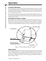
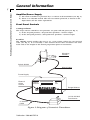
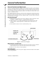
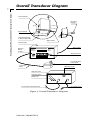
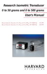
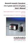
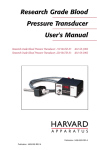
Research Isometric Transducer
0 to 50 grams and 0 to 500 grams
User's Manual
Research Isometric Transducer 0 to 50 g and 0 to 500 g, 110 VAC/60 Hz
MA1 72-4482
Research Isometric Transducer 0 to 50 g and 0 to 500 g, 220 VAC/50 Hz
MA1 72-4485
Publication 5408-005-REV-A
WEEE/RoHS Compliance Statement
EU Directives WEEE and RoHS
To Our Valued Customers:
We are committed to being a good corporate citizen. As part of that commitment,
we strive to maintain an environmentally conscious manufacturing operation. The
European Union (EU) has enacted two Directives, the first on product recycling
(Waste Electrical and Electronic Equipment, WEEE) and the second limiting the use
of certain substances (Restriction on the use of Hazardous Substances, RoHS).
Over time, these Directives will be implemented in the national laws of each EU
Member State.
Once the final national regulations have been put into place, recycling will be offered
for our products which are within the scope of the WEEE Directive. Products falling
under the scope of the WEEE Directive available for sale after August 13, 2005 will
be identified with a “wheelie bin” symbol.
Two Categories of products covered by the WEEE Directive are currently exempt
from the RoHS Directive – Category 8, medical devices (with the exception of
implanted or infected products) and Category 9, monitoring and control instruments.
Most of our products fall into either Category 8 or 9 and are currently exempt from
the RoHS Directive. We will continue to monitor the application of the RoHS
Directive to its products and will comply with any changes as they apply.
• Do Not Dispose Product with Municipal Waste
• Special Collection/Disposal Required
Table of Contents
Harvard Apparatus Research Isometric Transducer User’s Manual
1
SUBJECT
PAGE NO.
Warranty and Repair Information ........................2
Theory of Operation ..............................................3
Operation:
Transducer Mounting..........................................4
Positioning the Muscle Sample ..........................4
Splash Shield......................................................4
General Information:
Amplifier/Power Supply ......................................5
Front Panel Controls:
Range Selector Switch ..................................5
Offset ............................................................5
Internal Controls and Adjustments ....................6
Electrical Output ................................................6
Maintenance and Storage ..................................6
Serial Number ....................................................6
Transducer Diagram ..........................................7
Publication 5408-005-REV-A
Warranty and Repair Information
Harvard Apparatus Research Isometric Transducer User’s Manual
2
Serial Numbers
All inquires concerning our product should refer to the serial number of the unit(s).
Warranty
Harvard Apparatus warranties the instrument(s) for a period of two years from date of
purchase.At its option, Harvard Apparatus will repair or replace the unit(s) if it is found
to be defective as to workmanship or material.
This warranty does not extend to damage resulting from misuse, neglect or abuse, normal wear and tear, or accident.
This warranty extends only to the original customer purchaser.
IN NO EVENT SHALL HARVARD APPARATUS BE LIABLE FOR INCIDENTAL OR
CONSEQUENTIAL DAMAGES. Some states do not allow exclusion or limitation of
incidental or consequential damages so the above limitation or exclusion may not
apply to you. THERE ARE NO IMPLIED WARRANTIES OF MERCHANTABILITY,
OR FITNESS FOR A PARTICULAR USE, OR OF ANY OTHER NATURE. Some states
do not allow this limitation on an implied warranty, so the above limitation may not
apply to you.
If a defect arises within the two-year warranty period, promptly contact Harvard
Apparatus, Inc. 84 October Hill Road, Holliston, Massachusetts 01746-1371
using our U.S. only toll free number 1-800-272-2775 or dial (508) 893-8999. Goods will
not be accepted for return unless an RMA (returned materials authorization) number
has been issued by our customer service department.The customer is responsible for
shipping charges. Please allow a reasonable period of time for completion of repairs,
replacement and return. If the unit is replaced, the replacement unit is covered only
for the remainder of the original warranty period dating from the purchase of the original device.
This warranty gives you specific rights, and you may also have other rights which vary
from state to state.
Repair Facilities and Parts
Harvard Apparatus stocks replacement and repair parts. When ordering, please
describe parts as completely as possible, preferably using our part numbers. If practical, enclose a sample or drawing.We offer a complete reconditioning service.
CAUTION: Not for clinical use on human patients.
Publication 5408-005-REV-A
Theory of Operation
Harvard Apparatus Research Isometric Transducer User’s Manual
3
This transducer operates on the principle of converting picofarad capacitance changes
into an amplified DC output voltage by means of a patented circuit (U.S. Patent
Number 412144).
The transducer consists of a stiff beam suspended between two capacitor plates. This
forms a differential capacitor. Using this principal, the beam can be exceptionally stiff,
approaching the ideal of measuring force without motion. As an example, for a force
of 1 gram, the beam deflection is a maximum of only 10 microns in either the 50 or
500 gram range mode. The linearity is within ±1% with a high DC voltage output and
freedom from drift.
Publication 5408-005-REV-A
Operation
Harvard Apparatus Research Isometric Transducer User’s Manual
4
Transducer Mounting
The transducer comes with an integral short, rigid mounting handle. (See Fig. 1 and 2)
To obtain maximum advantage of stiff beam characteristics of the transducer, it should
be positioned and held in place with hardware that is as rigid as possible such that all
the muscle forces are recorded (i.e. captured) and none are lost in extraneous deflections of the mounting hardware.
The 55-0640 Harvard Research Support Stand is the mounting hardware of choice. Its
massive, durable construction will not deflect under load. The transducer itself should
be positioned such that the output cable at the rear of the transducer ends up on the
bottom. (See Fig. 1 and 2)
Positioning the Muscle Sample
The transducer has a short shaft/rod with a groove that projects from the front. See
Figure 1 below. One end of the non-stretching string must be formed into a loop and
fastened into the groove on the shaft. The other end of the string is subsequently
attached to the muscle preparation. The string must be at right angle to the transducer shaft and be pulled straight downward once the final setup has been completed.
Mounting Handle
Grooved Shaft
90˚
Splash Shield
Non-Stretch String
to Muscle Specimen
Output Cable
Figure 1. Positioning the Muscle Sample
Splash Shield
The transducer is equipped with a transparent, removable plastic shield which helps
to prevent buildup of salts (i.e. corrosives) which may otherwise tend to accumulate
on the transducer beam shaft and migrate into the tranducer circuit. (See Fig. 1) In
time, this salt buildup can deteriorate performance. The cord/cable/wire from the
beam must be directed through the slot in the splash shield without touching the
edges. See Figure 1 above.
Publication 5408-005-REV-A
General Information
Harvard Apparatus Research Isometric Transducer User’s Manual
5
Amplifier/Power Supply
a) The entire transducer is powered by a 12 volt AC wall transformer. (See Fig. 2)
b) There is no ON/OFF switch. The unit can remain powered, as shown on the
digital meter, for the entire experiment.
Front Panel Controls
A. Range Selector
The range selector switch has two positions: 50 gram and 500 gram (See Fig. 2)
1) In the 50 gram position, a 50 gram force produces a 5 VDC output.
2) In the 500 gram position, a 500 gram force produces a 5 VDC output.
B. Offset
The OFFSET control enables the user to set a zero output voltage for any pre-load
value. (See Fig. 2) It is essentially a “Tare Control” device since it balances out static
loads such as the weight of the muscle preparation prior to contraction.
Mounting
Handle
Splash Shield
Signal Cable
Power Supply
External
Offset
Control
ISOMETRIC
TRANSDUCER
VOLTS
OUTPUT
Range Selector
OFFSET
12 Volt AC Wall
Transformer
12 Volt AC
Cable
Figure 2. Diagram of Isometric Transducer
Publication 5408-005-REV-A
General Information
Harvard Apparatus Research Isometric Transducer User’s Manual
6
Internal Controls and Adjustments
On the rear panel of the power supply are three small access holes to the trim pots.
(See Fig. 3) The high and low gain trim pots are used to adjust the range. The righthand trim pot is factory set to deliver 5.0 VDC for 50 gram. The center trim pot is factory set to deliver 5.0 VDC for 500 gram. Either can be adjusted to deliver more or less
output as conditions dictate.
The OFFSET adjustment trim pot is located on the extreme left and has been factory
adjusted to center the offset control. It also can be adjusted in situations where the
front panel offset control does not have sufficient range. It can be used to correct for
static loads up to 2.5 grams.
Electrical Output
a) Binding post are provided on the power supply for output connections. Red
is positive (+); black is negative (–) and also ground. (See Fig. 3)
b) Output voltage is 0 to 5.0 VDC depending upon the position of the range
selector switch. Output impedance is 2 kΩ for direct connection to all
recorders.
c) The transducer is linear to 100% overload (1000 g = 4 V).
Figure 3. Electrical Output
Maintenance and Storage
a) No special precautions are required other than preventing corrosive solutions
from entering the space where the output shaft exits the transducer.
b) When not in use, store in a clean, dry place.
Serial Number
The serial number is located on the power supply circuit board. Refer to this number
in any correspondence.
Publication 5408-005-REV-A
Overall Transducer Diagram
Harvard Apparatus Research Isometric Transducer User’s Manual
7
Grooved Shaft
Mounting
Handle
90˚
Splash Shield
Non-Stretch String
to Muscle Specimen
Signal Cable
Power Supply
Signal Cable
External
Offset
Control
ISOMETRIC
TRANSDUCER
VOLTS
OUTPUT
Range Selector
OFFSET
12 Volt AC Wall
Transformer
12 Volt AC
Cable
BNC Connector
High-Gain Trim
Low-Gain Trim
Offset Trim
To Transducer Sensing Head
Figure 4. Overall Transducer Diagram
Publication 5408-005-REV-A
12 Volt AC Input