1
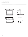
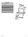
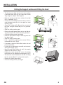
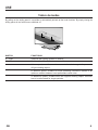
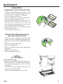
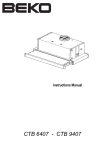
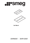
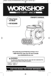
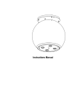
User
Manual
Bedienungsanleitung
Manual de Instruções
Manuel d’Instructions
Model ZHP6022
ZHP9022
Gebruiksaanwijzing
Manual de instrucciones
INDEX
RECOMMENDATIONS AND SUGGESTIONS...................................................................................................................... 3
CHARACTERISTICS............................................................................................................................................................. 4
INSTALLATION..................................................................................................................................................................... 6
USE....................................................................................................................................................................................... 8
MAINTENANCE.................................................................................................................................................................... 9
GB 2
RECOMMENDATIONS AND SUGGESTIONS
The Instructions for Use apply to several versions of this appliance. Accordingly, you may find descriptions of individual features that do not apply to your
specific appliance.
INSTALLATION
• The manufacturer will not be held liable for any damages resulting from incorrect or improper installation.
• The minimum safety distance between the cooker top and the extractor hood
is 650 mm (some models can be installed at a lower height, please re-fer to the
paragraphs on working dimensions and installation).
• Check that the mains voltage corresponds to that indicated on the rating plate
fixed to the inside of the hood.
• For Class I appliances, check that the domestic power supply guarantees adequate earthing.
Connect the extractor to the exhaust flue through a pipe
of minimum diame-ter 120 mm. The route of the flue must be as short as possible.
• Do not connect the extractor hood to exhaust ducts carrying combustion fumes
(boilers, fireplaces, etc.).
• If the extractor is used in conjunction with non-electrical appliances (e.g. gas
burning appliances), a sufficient degree of aeration must be guaranteed in the
room in order to prevent the backflow of exhaust gas. The kitchen must have
an opening communicating directly with the open air in order to guar-antee the
entry of clean air.
�����������
USe
• The extractor hood has been designed exclusively for domestic use to eliminate kitchen smells.
• Never use the hood for purposes other than for which it has been designed.
• Never leave high naked flames under the hood when it is in operation.
• Adjust the flame intensity to direct it onto the bottom of the pan only, making sure
that it does not engulf the sides.
• Deep fat fryers must be continuously monitored during use: overheated oil can
burst into flames.
• Do not flambè under the range hood; risk of fire
• This appliance is not intended for use by persons (including children) with reduced physical, sensory or mental capabilities, or lack of experience and knowledge, unless they have been given supervision or instruction concern-ing use of
the appliance by a person responsible for their safety.
• Children should be supervised to ensure that they do not play with the appliance.
MAiNTENance
• Switch off or unplug the appliance from the mains supply before carrying out any
maintenance work.
• Clean and/or replace the Filters after the specified time period (Fire hazard).
• Clean the hood using a damp cloth and a neutral liquid detergent.
The symbol
on the product or on its packaging indicates that this product may not be treated as household waste. Instead it shall be handed
over to the applicable collection point for the recycling of electrical and electronic equipment. By ensuring this product is disposed of correctly, you
will help prevent potential negative consequences for the environment and human health, which could otherwise be caused by inappropriate waste
handling of this product. For more detailed information about recycling of this product, please contact your local city office, your household waste
disposal service or the shop where you purchased the product.
GB 3
ChARACTERiSTICS
Dimensions
����
����
����� �����
GB 4
Components
Ref. Q.ty
1
1
Product Components
Hood Body, complete with: Controls, Light,
Blower, Filters
Directional Air Outlet grille
Flange ø 120 mm
Closing element
8
10a
20
1
1
1
Ref.
12a
12e
12f
Q.ty
4
2
3
Installation Components
Screws 3,5 x 16
Screws 2,9 x 12,7
Screws 2,9 x 9,5
Q.ty
1
Documentation
Instruction Manual
12e
8
10a
1
12a
20
12f
GB 5
INSTALLATION
Drilling the Support surface and Fitting the Hood
• The Hood can be fitted directly on the lower surface
of the Wall Units (650 mm min. above the Cooker
Top) using the snap-on Side Supports.
• Make an opening on the lower surface of the Wall
Unit, as indicated. (fig.1)
• Choose the correct flange measure basing on the air
outlet diameter and insert it to the upper air outlet
opening. (fig.2)
• Screw the closing profile 20 onto the rear part of
the hood, using the screws 12f (2.9 x 9.5) provided.
(fig.3)
• Open the sliding suction panel.
• Remove the metal grease filters one by one after having disconnected the relative fas-tening elements.
• Close the sliding suction panel again.
• Insert the Hood until the snap-on side sup-ports click
into place. (fig.4)
• Open the sliding suction panel.
• Lock in position by tightening the screws Vf from
underneath the Hood. (fig.4)
• If necessary, adjust the whole filter holder unit and
proceed as follows:
• Loosen the four adjustment screws Vr and close the
sliding panel again. (fig.5)
• Move the entire filter holder unit until it is properly
aligned with the wall unit. (fig.6)
• Keeping the hood canopy still, remove the sliding
panel and lock the adjustment screws again. (fig.5)
• The hood can now be fastened to the wall unit using
the four screws 12a (3.5 x 16) provided. (fig.7)
• Replace the metal grease filters.
• Close the sliding suction panel again.
�
�
���
���
�
�
�
�
�
���
GB 6
Connections
Ducting Version AirExhaust System
When installing the hood in ducting version, a rigid or
a flexible pipe with the diameter corresponding to the
flange diameter is used in order to connect the hood
to the air outlet piping.
• Fix the pipe with an adequate quantity of pipe clamps
(not supplied).
• Remove possible charcoal filters.
12e
Recirculation Version AireOutlet
8
• Cut a hole ø 125 mm in any shelf that may be positioned over the hood.
• Insert the flange 10a on the hood body outlet.
• Connect the flange to the outlet on the shelf over
the hood using a flexible or rigid pipe ø120 mm.
• Fix the pipe in position using sufficient pipe clamps
(not supplied).
• Fix the directional grille 8 on the recirculation air outlet
using the 2 screws 12e (2,9 x 12,7) provided.
• Ensure that the activated charcoal filters have been
inserted.
Electrical Connection
• Connect the hood to the mains through a two-pole
switch having a contact gap of at least 3 mm..
GB 7
USE
Tablero de mandos
By pulling out the sliding panel it is possible to automatically activate all the hood functions. By simply closing the
sliding panel all the functions are switched off
L
M
SWITCH
FUNCTIONS
L Light Switches the lighting system on and off
M Motor
Switches the extractor motor on and off
1. Low speed, used for a continuous and silent air change in the presence
of light cooking vapour.
2. Medium speed, suitable for most operating conditions, thanks to an
optimum relation between hood performance and noise.
3. Maximum speed, suitable when the highest cooking vapour emission
has to be eliminated for longer periods.
GB 8
MAiNTENaNce
Grease filters
CLEANING METAL CASSETTE GREASE FILTERS
• The filters must be cleaned every 2 months, or more
frequently in case of particularly heavy use of the
hood. Filters can be washed in a dishwasher.
• Pull out the sliding suction panel.
• Remove the filters one by one, after having disconnected the relative fastening elements.
• Wash the filters, taking care not to bend them. Let
them get dry before refitting them. (The colour of the
filter surface may change throughout the time but this
has no influence to the filter efficiency).
• When refitting the filters, make sure that the handle
is visible on the outside.
• Close the sliding suction panel.
Charcoal filter (Recycling version)
REPLACING CHARCOAL FILTERS
• These filters are not washable and cannot be regenerated, and must be replaced approximately every
four months or more frequently by particularly heavy
use.
• Pull out the sliding suction panel.
• Remove the grease filters.
• Remove the saturated carbon filter by releasing the
fixing hooks.
• Replace the grease filters.
• Close the sliding suction panel.
Lighting
LIGHT REPLACEMENT
40 W incandescent light.
• Remove the metal terminals fixing the light cover.
• Slide the light cover to the right until the left hand is
free. Lower it slightly and slide it to the left to free
it completely.
• Unscrew the bulbs and replace them with new ones
having the same characteristics.
• Replace the lighting support in reverse order.
GB 9