1
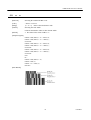
User’s Manual
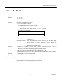
THERMAL PRINTER MECHANICAL
CONTROL LSI
MODEL
CBM-202PC-04
Rev.1.01 Added notes Dec.14th,1998
CBM-202PC-04 User’s Manual
<CAUTIONS>
1. Prior to using the printer, read this manual thoroughly for correct operation.
After reading the manual, keep it
carefully at hand for your future reference.
2. The information herein is subject to change without prior notice due to technical improvements.
Upon actual
use of the printer, inquire for the up-to-date specifications.
3. It is strictly prohibited to copy part or all of the information contained in this manual without our prior
permission.
4. If you have any question about the information herein or notice any clerical error or omission, please contact us.
5. We will not be responsible for the effects from the results of operating the printer, regardless of Section 4.
6. We cannot guarantee that the information herein does not infringe upon the industrial property, etc. of a third
party, except when there is a written agreement to that effect.
2
CITIZEN
CBM-202PC-04 User’s Manual
CONTENTS
1.
OUTLINE ............................................................................................................................................................ 5
1.1 Applicable Printer ........................................................................................................................................ 5
2.
MAINTENANCE AND SERVICE.................................................................................................................... 6
3.
BASIC SPECIFICATIONS................................................................................................................................ 7
3.1 Shapes and Dimensions.................................................................................................................................. 7
3.2 Structure ........................................................................................................................................................ 7
3.3 Data Transfer Method .................................................................................................................................... 7
3.4 Printing Function ........................................................................................................................................... 7
3.5 Operating Voltage and Power Consumption .................................................................................................... 7
3.6 Operating Frequency...................................................................................................................................... 7
4.
HARDWARE SPECIFICATIONS .................................................................................................................... 8
4.1 Absolute Maximum Ratings........................................................................................................................... 8
4.2 Electrical Characteristics................................................................................................................................ 8
4.3 Pin Layout and Functions............................................................................................................................... 9
4.4 Gate Array Pin Layout and Functions............................................................................................................13
4.5 Reset Circuit .................................................................................................................................................14
4.6 Oscillation Circuit.........................................................................................................................................15
4.7 Head-up Detection Circuit.............................................................................................................................16
4.8 Head Control Circuit.....................................................................................................................................17
4.9 Paper End Detection Circuit ..........................................................................................................................18
4.10 Motor Control Circuit ...................................................................................................................................19
4.11 Auto Cutter Control Circuit...........................................................................................................................20
4.12 Parallel Interface Circuit ...............................................................................................................................21
4.13 Serial Interface Circuit ..................................................................................................................................23
4.14 Switch Circuit...............................................................................................................................................24
4.15 Error Output Circuit ......................................................................................................................................25
4.16 Function Selection Circuit.............................................................................................................................27
4.17 External RAM Interface ................................................................................................................................30
3
CITIZEN
CBM-202PC-04 User’s Manual
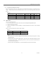
5.
PRINTER MECHANISM CONTROL SYSTEM ......................................................................................... 33
5.1 Head Drive ...................................................................................................................................................33
5.1.1
Head Dividing Method .....................................................................................................................33
5.1.2
Thermal Head Application Energy ....................................................................................................34
5.2 Motor Drive..................................................................................................................................................34
5.3 Auto Loading................................................................................................................................................35
6.
SELF-PRINTING ............................................................................................................................................. 36
7.
OPERATION TIMING .................................................................................................................................... 37
8.
SPECIFICATIONS OF PACKAGE................................................................................................................ 38
9.
PRECAUTIONS FOR MOUNTING .............................................................................................................. 39
9.1 Precautions ...................................................................................................................................................39
9.2 Reflow Mounting..........................................................................................................................................39
9.3 Recommended Conditions for Different Mounting Methods ..........................................................................39
9.4 Clearing Method ...........................................................................................................................................41
9.5 Storage Method.............................................................................................................................................41
10. PRINT CONTROL FUNCTIONS................................................................................................................... 42
10.1 Command List ..............................................................................................................................................42
10.2 Command Details .........................................................................................................................................44
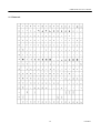
11. CHARACTER CODES TABLE...................................................................................................................... 86
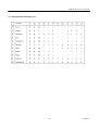
11.1 International..................................................................................................................................................86
11.2 Domestic ......................................................................................................................................................87
11.3 International Character Codes Table ..............................................................................................................88
4
CITIZEN
CBM-202PC-04 User’s Manual
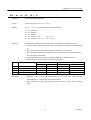
1. OUTLINE
This LSI is designed to control the line thermal printer LT-286 by using our Gate Array.
It has the following
features.
(1) Capable of providing high-quality printing by detecting a temperature and automatically correcting
printing density.
(2) Capable of providing high-quality printing by detecting a voltage and automatically correcting printing
density.
(3) Capable of selecting the parallel or serial interface.
(4) Capable of selecting printing density via a function selection terminal.
(5) Capable of printing a bar code.
(6) Capable of printing double-width/height characters, bit images, and so on by various commands.
1.1
Applicable Printer
LSI Name
Applicable Mechanism
CBM-202PC-04
LT-286
5
CITIZEN
CBM-202PC-04 User’s Manual
2. MAINTENANCE AND SERVICE
For the information on maintenance and service, please contact our dealer or at the following address.
Northern America
Other Areas
CBM America Corporation
Japan CBM Corporation
Service Center
Information Systems Division
365 Van Ness Way
CBM Bldg.,5-68-10 Nakano
Suit 510
Nakno-ku, Tokyo 164-0001
Torrance, CA 90501, U.S.A
Japan
TEL
+1-310-781-1460
TEL
+81-3-5345-7540
FAX
+1-310-781-9157
FAX
+81-3-5345-7541
6
CITIZEN
CBM-202PC-04 User’s Manual
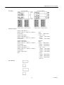
3. BASIC SPECIFICATIONS
3.1
Shape and Dimensions (Refer to the “8. SPECIFICATIONS OF PACKAGE”.)
100-pin flat package
3.2
Structure
C-MOS LSI
3.3
Data Transfer Method
Parallel transfer or serial transfer (Selectable)
(1) 8-bit parallel transfer (CENTRONICS based)
(2) Asynchronous serial transfer (Selectable)
1,200, 2,400, 4,800, 9,600, or 19,200 bps
Parity: Odd, Even, or None parity;
3.4
8 bits
Printing Function
(1) Printing columns and printing speed
Model
Digits
Total Dots
Character Size (mm)
32
LT-286
Printing Speed (m/s)
1.25×3.00(Font A)
384
42
50
0.88×3.00(Font B)
Note) The printing speed above applies when the thermal printer is driven in the following environment:
3.5
3.6
• Drive voltage(VH)
=
7.2 V
• Thermal head temperature
=
30°C or more
• Simultaneous power-on(print) dots
=
Within 64 dots
Operating Voltage and Power Consumption
• Voltage
: 5V DC ±5 %
• Current consumption
: 80mA at maximum
Operating Frequency
• 16 MHz
7
CITIZEN
CBM-202PC-04 User’s Manual
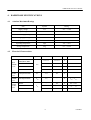
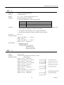
4. HARDWARE SPECIFICATIONS
4.1
4.2
Absolute Maximum Ratings
Item
Symbol
Rating
Supply voltage
Vcc
–0.3 ~ +7.0V
Input voltage
Vi
–0.3 ~ Vcc+0.3V
Reference supply voltage
VREF
–0.3 ~ AVcc+0.3V
Analog supply voltage
AVcc
–0.3 ~ +7V
Analog input voltage
VAN
–0.3 ~ AVcc+0.3V
Operating temperature
Topr
–20 ~ +75°C
Storage temperature
Tstg
–55 ~ +125°C
Electrical Characteristics
Item
Symbol
MIN
MAX
Unit
Vcc–0.7
Vcc+0.3
V
Vcc×0.7
Vcc+0.3
V
THEM
2.0
AVcc+0.3
V
Others
2.0
Vcc+0.3
V
RES,STBY,NM1
MD0,MD1,MD2
Input
"HIGH"
Level
Input
"LOW"
level
Output
"HIGH"
level
Output
"LOW"
level
EXTAL
VIH
Condition
All input terminals
VIL
–0.3
0.5
V
All output terminals
V0H
3.5
–
V
IOH = –1mA
–
0.4
V
IOH = 2.6mA
–
1.0
V
IOL = 10mA
0.4
V
IOL = 1.6mA
RESO
LEDER,LEDPE
V0L
Others
8
CITIZEN
CBM-202PC-04 User’s Manual
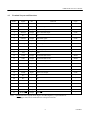
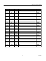
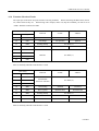
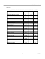
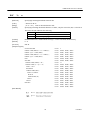
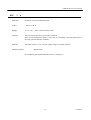
4.3
Terminal Layout and Functions
Pin No.
Signal
I/O
1
VCC
–
2
LFSW
Input
3
LEDER
4
Function
VCC
Logic
–
LF switch input
LOW
Output
Error LED output
LOW
LEDPE
Output
Paper end LED output
LOW
5
NC
–
6
LATCH
Output
7
PAPER
8
NC
–
Head latch signal
LOW
Input
Paper end input NC
HIGH
DRQ
Input
DMA request
LOW
9
NC
–
10
RES0
Output
11
VSS
–
12
DTR
Output
Serial DTR (RS-232C)
HIGH
13
TXD
Output
Serial TXD (RS-232C)
HIGH
14
DI
Input
Print head output data
HIGH
15
RXD
Input
Serial RXD (RS-232C)
HIGH
16
CP
Input
Print head clock
HIGH
17
NC
–
18
CTSW
Input
19
NC
–
NC
–
20
NC
–
NC
–
21
NU
–
RESERVED
–
22
VSS
–
GND
–
23
MOTORA
Output
Motor A
–
24
MOTORB
Output
Motor B
–
25
MOTORA
Output
Motor A
–
Note)
NC
–
Watchdog output
GND
LOW
–
NC
–
Cutter switch input
LOW
For notation of the signals whose logic is "LOW"(Negative), a representation of
XXX(Upper line) will be omitted for the subsequent notations.
9
CITIZEN
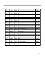
CBM-202PC-04 User’s Manual
Pin No.
Signal
I/O
Function
26
MOTORB
Output
27
D0
I/O
D0
HIGH
28
D1
I/O
D1
HIGH
29
D2
I/O
D2
HIGH
30
D3
I/O
D3
HIGH
31
D4
I/O
D4
HIGH
32
D5
I/O
D5
HIGH
33
D6
I/O
D6
HIGH
34
D7
I/O
D7
HIGH
35
VCC
–
36
A0
Output
A0
HIGH
37
A1
Output
A1
HIGH
38
A2
Output
A2
HIGH
39
A3
Output
A3
HIGH
40
A4
Output
A4
HIGH
41
A5
Output
A5
HIGH
42
A6
Output
A6
HIGH
43
A7
Output
A7
HIGH
44
VSS
–
45
A8
Output
A8
HIGH
46
A9
Output
A9
HIGH
47
A10
Output
A10
HIGH
48
A11
Output
A11
HIGH
49
A12
Output
A12
HIGH
50
A13
Output
A13
HIGH
Motor B
Logic
–
VCC
–
GND
–
10
CITIZEN
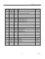
CBM-202PC-04 User’s Manual
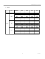
Pin No.
Signal
I/O
Function
Logic
51
A14
Output
A14
HIGH
52
A15
Output
NC
–
53
A16
Output
NC
–
54
A17
Output
NC
–
55
A18
Output
NC
–
56
A19
Output
NC
–
57
VSS
–
GND
–
58
P60
Output
NC
–
59
P61
Output
NC
–
60
P62
Output
NC
–
61
φ
Output
Clock output
HIGH
62
STBY
Input
(Pull up to VCC at 10kΩ)
LOW
63
RES
Input
Reset input
LOW
64
NMI
Input
(Pull up to VCC at 10kΩ)
LOW
65
VSS
–
GND
–
66
EXTAL
–
EXTAL (16MHz)
–
67
XTAL
–
XTAL (16MHz)
–
68
VCC
–
VCC
–
69
P63
Output
NC
–
70
RD
Output
RD
LOW
71
HRW
Output
HRW
LOW
72
P66
Output
NC
73
MD0
Input
(Pull up to VCC at 10kΩ)
HIGH
74
MD1
Input
(Pull down to GND at 10k Ω)
LOW
75
MD2
Input
(Pull up to VCC at 10kΩ)
HIGH
–
11
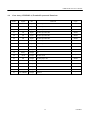
CITIZEN
CBM-202PC-04 User’s Manual
Pin No.
Signal
I/O
Function
Logic
76
AVCC
–
VCC
–
77
VREF
–
VCC
–
78
THERM
Input
Head temperature detection terminal
–
79
NC
Input
(Pull down to GND at 10k Ω)
–
80
DETECV
Input
Voltage detection terminal
–
81
NC
Input
(Pull down to GND at 10k Ω)
–
82
NC
Input
(Pull down to GND at 10k Ω)
–
83
NC
Input
(Pull down to GND at 10k Ω)
–
84
NC
Input
(Pull down to GND at 10k Ω)
–
85
NC
Input
(Pull down to GND at 10k Ω)
–
86
AVSS
–
GND
–
87
STB
Input
Parallel data interrupt
LOW
88
HEADUP
Input
Head up detection terminal
LOW
89
CS2
Output
Gate Array chip select
LOW
90
CS1
Output
RAM chip select
LOW
91
CS0
Output
Kanji ROM chip select
LOW
92
VSS
–
93
NC
94
GND
–
Output
NC
–
STRB1
Output
Head strobe 1
HIGH
95
STRB2
Output
Head strobe 2
HIGH
96
STRB3
Output
Head strobe 3
HIGH
97
STRB4
Output
Head strobe 4
HIGH
98
STRB5
Output
Head strobe 5
HIGH
99
STRB6
Output
Head strobe 6
HIGH
100
DSR
Input
Serial DSR (RS-232C)
HIGH
12
CITIZEN
CBM-202PC-04 User’s Manual
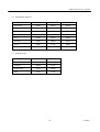
4.4
Gate Array (CBM202LA) Terminal Layout and Functions
Pin No.
Signal
I/O
Function
44
D7
Input
Parallel input data D7
HIGH
45
D6
Input
Parallel input data D6
HIGH
46
D5
Input
Parallel input data D5
HIGH
47
D4
Input
Parallel input data D4
HIGH
48
D3
Input
Parallel input data D3
HIGH
49
D2
Input
Parallel input data D2
HIGH
50
D1
Input
Parallel input data D1
HIGH
51
D0
Input
Parallel input data D0
HIGH
52
STROBE
Input
Parallel STROBE
LOW
55
BUSY
Output
Parallel BUSY
HIGH
58
PAO7
Output
NC
–
59
ACK
Output
Parallel ACK
–
61
PE
Output
Parallel paper end
HIGH
62
FAULT
Output
Parallel FAULT
LOW
63
CUTTERA
Output
Cutter A
–
64
CUTTERB
Output
Cutter B
–
65
CUTTERC
Output
Cutter C
–
67
CUTTERD
Output
Cutter D
–
13
Logic
CITIZEN
CBM-202PC-04 User’s Manual
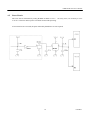
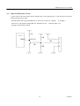
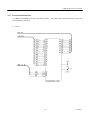
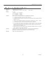
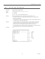
4.5
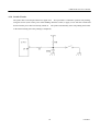
Reset Circuit
The reset state is effectuated by setting the RES terminal to "Low."
To surely reset, it is necessary to set it
to "Low" at least for 20ms at power-on and for 625ns while operating.
If an external reset is not used, the parts enclosed by dotted lines are not required.
14
CITIZEN
CBM-202PC-04 User’s Manual
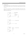
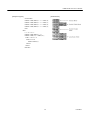
4.6
Oscillation Circuit
The oscillation circuit incorporates a clock oscillator which generates a system clock and an internal clock.
There are two methods to supply a clock; one is to connect a ceramic oscillator, and the other is to input an
external clock.
When using the ceramic oscillator, we recommend the CSTCS16.00MXOC3 (With capacitor) made by
MURATA.
When inputting the external clock, you may either open the XTAL terminal or input an
antiphase clock to the XTAL terminal.
15
CITIZEN
CBM-202PC-04 User’s Manual
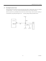
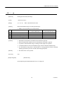
4.7
Head-up Detection Circuit
Print head up/down is detected by a head-up sensor built in the printer so that the printer will not be energized
on with the head up.
The circuit is "opened" when the print head is up, and "closed" when down.
When the print head is up, HEADUP (Pin 88) of the CPU is turned to "High," and if the printer is printing, it
will immediately stop printing and output an error.
It resumes printing when the print head is down.
16
CITIZEN
CBM-202PC-04 User’s Manual
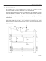
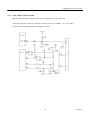
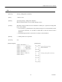
4.8
Head Control Circuit
VP is controlled in order to prevent electrolytic corrosion of the printing head.
HVC(Pin-4) of the Gate
Array is turned to "HIGH" when turning on VP, and turned to "LOW" when turning it off.
A temperature detection circuit is provided in order to prevent deterioration of the printing quality or breakage
of the printing head due to a temperature.
This function detects a temperature by means of a thermistor
included in the printer and determines according to that temperature how much energy should be applied to
the printing head.
If a temperature of the printing head exceeds 60•, it will stop printing to prevent breakage
of the printing head.
As a protection when the CPU crashes, connect in such a manner that the Gate Array will be reset by an
output from the watchdog timer of the CPU.
The CPU itself has been set so that it will be reset.
So that
the head strobe will not be turned to ON at that time, be sure to insert one pull -up resistor into STRB1 through
STRB3, respectively.
17
CITIZEN
CBM-202PC-04 User’s Manual
4.9
Paper End Detection Circuit
A paper sensor built in the printer detects whether there is the printing paper, so that the printer will not be
turned on when it has no paper.
When the printer has no paper,PAPER (P in 7) of the CPU is turned to "HIGH."
under way, it will stop after printing that line, and output an error.
If printing is
When the paper is set,
printing is automatically resumed.
18
CITIZEN
CBM-202PC-04 User’s Manual
4.10 Motor Control Circuit
Avoid running the motor continuously for 15 minutes or more.
19
CITIZEN
CBM-202PC-04 User’s Manual
4.11 Auto Cutter Control Circuit
This CPU has a function to control the auto cutter, using the Pin 33 of the Gate Array.
When the auto cutter is not used, set the Pin 33 of the Gate Array to "HIGH."
If se t to "LOW,"
the printer will not function properly, resulting in an alarm.
20
CITIZEN
CBM-202PC-04 User’s Manual
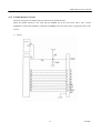
4.12 Parallel Interface Circuit
The Gate Array ports are mainly used to provide an 8-bit parallel interface.
When the parallel interface is not used, pull up STB(Pin 52) of the Gate Array with a 10kΩ resistor.
STB(Pin 87) of the CPU should be connected to INTR(Pin 56) of the Gate Array or pulled up with a 10kΩ
resistor.
1) Circuit
21
CITIZEN
CBM-202PC-04 User’s Manual
2) Gate Array Signals and Their Functions
Signal
Pin No.
I/O
Function
STROBE
52
Input
A signal to read in the data.(Negative logic)
D0
51
D1
50
D2
49
D3
48
D4
47
Input
Input data (Positive logic)
D5
46
D6
45
D7
44
ACK
59
Output
BUSY
55
Output
PE
FAULT
61
62
Output
Output
A signal to indicate that the data has been read. (Negative
logic)
A signal to indicate that the data cannot be received. (Positive
logic) Send the data when at "LOW."
A signal to be output when the paper runs out. (Positive logic)
A signal to indicate a printer error. (Negative logic)
GND
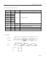
3)
Timing chart
T1, T2, T3
: 0.5 s
MIN
T4
: 270 ns
MAX
T5
: 2.3 s
TYP
T6
: 500 ms
MIN
22
CITIZEN
CBM-202PC-04 User’s Manual
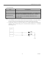
4.13 Serial Interface Circuit
A serial interface is an asynchronous serial system.
When the serial interface is not used, pull up RXD (Pin
15) and DSR (Pin 100) of the CPU with a 47kΩ resistor.
1) Circuit
2) Signal names and their functions
Signal Name
Pin No.
Input/Output
TXD
13
Output
RXD
15
Input
DSR
100
Input
DTR
12
Output
Function
Transmits the status.
If data reception is disabled when XON/XOFF is
selected, XOFF(13H) will be transmitted, and if data
reception is enabled, XON(11H) will be transmitted.
Received data signal. If a framing error or parity
error occurs, the relevant data will be printed "?".
With DTR/DSR selected, if this signal is "LOW," the
data will be transmitted from the CPU. If "HIGH,"
the data will be transmitted after the signal is turned
to "LOW."
Transmit the data when this signal is "LOW." If
written when it is "HIGH," an overrun error will
result, ignoring the data.
23
CITIZEN
CBM-202PC-04 User’s Manual
4.14 Switch Circuit
The printer has a switch input function for paper feed.
Also provided is a function to perform self -printing,
using this switch. (Turn on the power while holding down this switch, or apply a reset with this switch held
down when the power has been already turned on.
The printer automatically starts self-printing and returns
to the normal waiting state after printing is completed.)
24
CITIZEN
CBM-202PC-04 User’s Manual
4.15 Error Output Circuit
The printer has two kinds of error outputs. (Up to a current of 10mA is available in order to mainly indicate
with the LEDs.
If this limit is exceeded, the CPU may be destroyed.
Select the current control resistors,
LEDs, etc. carefully.)
LEDPE(Pin 4) of the CPU is a paper error exclusive output.
"LOW" is output when the printing pap er runs
out, and "HIGH" is output when new printing paper is set.
LEDER(Pin 3) of the CPU outputs other errors
in the following patterns.
1) Error output pattern
Error
Display Pattern
Description
Blinks at intervals of 200 ms
Memory error
Blinks at intervals of 150 ms(6 times) and 500
ms(1 time) as one cycle.
Illuminated until the error is reset.
Cutter lock
(Cutter error)
Head-up
Illuminated until the error is reset.
VH voltage error
Head temperature
error
Blinks at intervals of 1 sec.
Blinks at intervals of 500 ms
Macro execution wait
2) Error descriptions
Error
Description
Head-up
The head-up lever has been shifted up.
VH voltage error
When the VH voltage is beyond an allowable range (4.2 ~ 8.5V)
Head temperature error
Cutter lock
(ASC-220-5V)
When a head temperature is less than 0°C or 65°C or more
When the cutter is locked due to an external factor (Paper jam, etc.) at cutter
drive time
Note)
The upper-limit voltage of 8.5V for the VH voltage error is a voltage assumed only immediately after
charging the battery when the battery power is used and cannot be normally used.
A maximum
normal voltage is 7.2V.
25
CITIZEN
CBM-202PC-04 User’s Manual
3) Resetting methods
Error
Resetting Method
No-paper
Set the paper.
Head-up
Shift down the head-up lever.
VH voltage error
Head temperature error
Cutter lock(ACS-220-5v)
See Note 1.
Set the VH voltage to within the allowable range(4.2 ~ 8.5 V) and turn on the
power again, or set the LFSW(Pin-2) of the CPU to Active. See Note 2.
At the lower limit(Less than 0°C), printing is enabled at 0°C or more.
At the upper limit(65°C or more), printing is enabled at 60°C or less.
Eliminate the paper jam and set LFSW(Pin-2) of the CPU to Active or turn
on the power again.
Note)
1.
If auto loading has not been selected with the function selection J4(Jumper), set the paper manually.
If it has been selected, the auto loading function will be enabled to facilitate paper replacement.
2.
The upper-limit voltage of 8.5V for the VH voltage error is a voltage assumed only immediately after
charging the battery when the battery power is used and cannot be normally used.
A maximum
normal voltage is 7.2V.
26
CITIZEN
CBM-202PC-04 User’s Manual
4.16 Function Selection Circuit
The input port of the Gate Array has function selecting terminals.
on, connect them as they are.
When connecting the DIP switch, and so
When fixing with a Jumper, and so on, only the terminals you want to set to
"LOW" should be connected to GND.
Gate Array
Function
“LOW”
“HIGH”
PAI0
Auto cutter
Enabled
Disabled
32
PAI1
CR change
LF operation
Ignored
31
PAI2
Printing density
30
PAI3
DTR/XON – XOFF
29
PAI4
28
PAI5
27
PAI6
26
PAI7
Pin No.
Signal
33
See Table (3)
XON – XOFF
Interface
DTR/DSR
See Table (1)
PAI3 is valid only when the serial interface is used.
Gate Array
Function
“LOW”
“HIGH”
Pin No.
Signal
43
PBI0
42
PBI1
39
PBI2
38
PBI3
Auto loading
Enabled
Disabled
37
PBI4
Drive system
Dynamic drive
Fixed division
36
PBI5
Printing density
35
PBI6
Unused
–
–
34
PBI7
Unused
–
–
International
characters selection
See Table (2)
See Table (3)
PAI6 is valid only when the serial interface is used.
27
CITIZEN
CBM-202PC-04 User’s Manual
(1) Interface
Input
System
Parity
Baud Rate
PAI7
PAI6
PAI5
PAI4
Parallel
–
–
HIGH
HIGH
HIGH
HIGH
1200
HIGH
HIGH
HIGH
LOW
2400
HIGH
HIGH
LOW
HIGH
4800
HIGH
HIGH
LOW
LOW
9600
HIGH
LOW
HIGH
HIGH
19200
HIGH
LOW
HIGH
LOW
1200
HIGH
LOW
LOW
HIGH
2400
HIGH
LOW
LOW
LOW
4800
LOW
HIGH
HIGH
HIGH
9600
LOW
HIGH
HIGH
LOW
19200
LOW
HIGH
LOW
HIGH
1200
LOW
HIGH
LOW
LOW
2400
LOW
LOW
HIGH
HIGH
4800
LOW
LOW
HIGH
LOW
9600
LOW
LOW
LOW
HIGH
19200
LOW
LOW
LOW
LOW
None
Serial
Odd
Even
28
CITIZEN
CBM-202PC-04 User’s Manual
(2) International characters
International Characters
PBI2
PBI1
PBI0
Japan (JIS)
HIGH
HIGH
HIGH
Japan (Shift JIS)
HIGH
HIGH
LOW
Sweden
HIGH
LOW
HIGH
Denmark I
HIGH
LOW
LOW
U.K.
LOW
HIGH
HIGH
Germany
LOW
HIGH
LOW
France
LOW
LOW
HIGH
U.S.A.
LOW
LOW
LOW
PAI2
PBI5
Light
HIGH
HIGH
Standard
HIGH
LOW
Slightly dark
LOW
HIGH
Dark
LOW
LOW
(3) Printing density
Printing Density
29
CITIZEN
CBM-202PC-04 User’s Manual
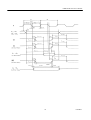
4.17 External RAM Interface
A 32 KB external SRAM is always required for printing.
The printer does not function properly unless the
external RAM is connected.
1) Circuit
30
CITIZEN
CBM-202PC-04 User’s Manual
2) Bus Timing
VCC= 5.0V±10%, AVCC= 5.0V±10%, VREF= 4.5V ~ AVCC, VSS=AVSS= 0V, φ = 2 ~ 16MHz,
TA= –20~75°C
Item
Symbol
MIN
MAX
Clock cycle time
t cyc
62.5
500
Clock pulse width "LOW" level time
t CL
20
–
Clock pulse width "HIGH" level time
t CH
20
–
Clock rise time
t CR
–
10
Clock fall time
t CF
–
10
Address delay time
t AD
–
30
Address hold time
t AH
10
–
Address strobe delay time
t ASD
–
30
Write strobe delay time
t WSD
–
30
Strobe delay time
t SD
–
30
Write data strobe pulse width 1
t WSW1
35
–
Write data strobe pulse width 2
t WSW2
65
–
Address setup time 1
t AS1
10
–
Address setup time 2
t AS2
40
–
Read data setup time
t RDS
20
–
Read data hold time
t RDH
0
–
Write data delay time
t WDD
–
60
Write data setup time 1
t WDS1
35
–
Write data setup time 2
t WDS2
5
–
Write data hold time
t WDH
20
–
Read data access time 1
t ACC1
–
55
Read data access time 2
t ACC2
–
115
Unit : ns
31
CITIZEN
CBM-202PC-04 User’s Manual
32
CITIZEN
CBM-202PC-04 User’s Manual
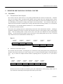
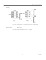
5. PRINTER MECHANISM CONTROL SYSTEM
5.1
Head Drive
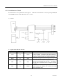
5.1.1 Thermal Head Control System
The LT-286 is driven by this LSI has a 1-line printing head divided into 6 blocks of 64 dots each. With this
LSI, you can choose either a Fixed Division Number System which drives the printing head by always
dividing it into 6 blocks of 64 dots each ora Variable Division Number System which simultaneously drives it
by consolidating several blocks according to the number of activate head dots. This selection is made with a
function selection terminal or command. For selecting with the function selecting terminal, see "4.16 Function
Selection Circuit. " For selecting with the command, see "10.2 Command Details."
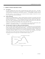
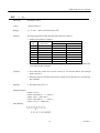
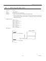
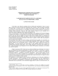
(1) Fixed Division Number System
The blocks of the printing head to be simultaneously driven have been determined in advance. Printing is
performed, dividing into 6 blocks of 64 dots each from the left corner of the printing surface of the printing
paper. Since the printing head is always driven in the same order, this method can assure high-quality
printing. In the Fixed Division Number System, the blocks of the printing head driven in the 1st and 2nd
steps of the motor have been determined as shown in Fig. 5.1.
Fig. 5.1
1st Block;
64 Dots
2nd Block;
64 Dots
3rd Block;
64 Dots
5th Block;
64 Dots
4th Block;
64 Dots
6th Block;
64 Dots
1st Step of Motor
2nd Step of Motor
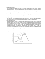
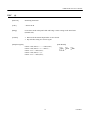
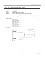
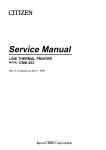
(2)
Variable Division Number System
This method counts the number of printing dots for each block of each printing head in the printing dot line
and drives the blocks collectively in such a manner not to exceed the maximum number of driving dots(64
dots). Fig. 5.2 shows an example when the number of printing dots in every block of 1 to 6 is 64 dots or
less.
Fig. 5.2
1st Block;
64 Dots
2nd Block;
64 Dots
3rd Block;
64 Dots
4th Block;
64 Dots
5th Block;
64 Dots
6th Block;
64 Dots
1st Step of Motor
2nd Step of Motor
Different from the Fixed Division Number System, this method drives all the printing heads in the 1st
step of the motor and simply feeds the paper in the 2nd step of the motor.
33
CITIZEN
CBM-202PC-04 User’s Manual
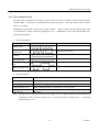
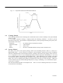
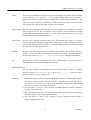
5.1.2 Thermal Head Application Energy
This LSI automatically controls the energy applied to the thermal head according to a temperature and Vp
voltage.
With the function selection terminal, print dens ity can be set to the following 4 kinds of ranks listed
in Fig. 5.3.
Fig. 5.3
5.2
Gate Array Pin-31
Gate Array Pin-36
Print Density
Level
LOW
LOW
HIGH
HIGH
LOW
HIGH
LOW
HIGH
Light
Standard
Slightly dark
Dark
0
1
2
3
Print Density
Rate
80 %
100 %
120 %
150 %
Motor Drive
There are the following features:
1) Prevents heat generation of the motor and restrains current consumption through PWM control.
2) Controls acceleration at start time.
3) Capable of providing fine control according to a voltage(VH) applied to the motor to realize optimum
paper feed.
Table 5.1 lists the maximum drive speeds at major voltages.
Table 5.1
VH Voltage
5V
6V
7.2 V
Max. Drive Speed
300 pps
490 pps
800 pps
At Auto Loading
75 pps
122 pps
200 pps
Notes)
• The maximum drive speed may slightly differ depending on the actual processing time or voltage
detection accuracy.
• If the head drive time becomes longer than the 1-step time of the motor during printing, the motor
will be driven after the head.
During printing, therefore, the drive speed will be slowed down due to
the head divided driving method.
• The drive speed at auto loading time is 1/4 of the maximum drive speed at each VH voltage.
34
CITIZEN
CBM-202PC-04 User’s Manual
5.3
Auto Loading
Auto loading is a function to facilitate replacement of the prin ting paper.
It is enabled by setting the function selection terminal(Gate Array Pin 38) to "LOW."
Functioning:
1)
Make the PE sensor detect PE once.
2)
Insert the printing paper into the printing paper insertion slot until the PE sensor detects the paper
again.
When this is done, the paper should be inserted at a right angle to the insertion slot; insert it
until it comes to the end.
3)
When this is done, if the head-up lever is shifted down, auto loading will be performed.
head-up lever is shifted up, shift it down.
4)
If the
Then, auto loading will be performed.
See Table 5.1 for the drive speed.
35
CITIZEN
CBM-202PC-04 User’s Manual
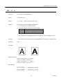
6. SELF-PRINTING
This LSI displays the setting of the function selection terminal and has a test print function to print Kanji when
printing the half-size characters or using the specified Kanji ROM(CBM-202KG-01).
The procedure is as follows:
1) Turn on the power, setting LFSW(Pin 2) of the CPU to "LOW."
Turn on both Vcc and VH almost
simultaneously, or turn on Vcc, followed by VH(Within 500ms after Vcc).
Fig. 6.1 shows a print sample(A print differs from actual dimensions).
Fig. 6.1
36
CITIZEN
CBM-202PC-04 User’s Manual
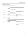
7. OPERATION TIMINGS
The following shows operation timings after resetting this CPU.
37
CITIZEN
CBM-202PC-04 User’s Manual
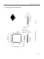
8. SPECIFICATIONS OF PACKAGE
38
CITIZEN
CBM-202PC-04 User’s Manual
9. PRECAUTIONS FOR MOUNTING
9.1
Precautions
If a relative humidity drops, the LSI will be electrified with static electricity more easily. The surface
mounting package must be stored in a dry atmosphere to prevent humidity absorption, but while it is being
stored, it will not be electrified because it will not have friction, etc. When handling or mounting it onto the
PCB where friction or electric discharge may be expected, the relative humidity is desired to be 45~75%
from a viewpoint of prevention of electrification.
9.2
Reflow Mounting
Using the screen printing method, etc., apply a constant amount of solder paste to the pattern on the PCB,
which was formed into the specified shape required for soldering the lead pins to a package mounting section,
and mount the package onto it. It will be temporarily fixed by the surface tension of the solder paste.
Then, if the solder is melted(reflow) again, the leads of the package and the pattern of the PCB will be
matched by a self-alignment effect through the surface tension of the molten solder.
Although the lead joint pattern design values of the PCB depend on the solder paste material used, reflow
condition, etc., they should be preferably 1.1~1.3 times larger than a soldered lead pin width.
9.3
Recommended Conditions for Different Mounting Methods
The most common mounting methods employed for the surface mounting devices are the infrared reflow
method, vapor phase reflow method, and flow solder method. As all of those mounting methods must heat
the entire package and apply a strong thermal stress, they require you to manage not only a temperature at the
solder joints, but that on the package surface, from a viewpoint of maintenance of reliability. Therefore, the
recommended mounting conditions are given in terms of the package surface temperature for the reflow
method, and in terms of solder temperature and immersion time for the flow solder method.
The following describes the concepts of the recommended conditions, using Fig. 9.1.
Fig. 9.1
39
CITIZEN
CBM-202PC-04 User’s Manual
1) Temperature gradient 1
If a temperature rises abruptly, each joint of the surface mounting device to the package will have
different temperature. As a result, the package may warp due to a difference in the thermal expansion
factor of the material, thus damaging the chip. Therefore, it is necessary to heed the upper limit of an
ascending rate. The lower limit depends on the activity rate of the reflow unit.
2) Preheating
The temperature of the parts and PCB is adjusted under the melting temperature of the solder to stabilize
soldering and ease a thermal shock. Generally, set to near the rated temperature of the surface
mounting device.
3) Temperature gradient 2
The upper limit of the ascending temperature is the same as in 1). The lower limit is determined by
necessity to contain the peak temperature and time men tioned in 4) within the specified ranges.
4) Peak temperature and time
In order to minimize damages on the package, the peak temperature and time must be most heeded.
Since the peak time has a direct effect on a drop of package strength and a steam pressure in the package,
it is desired to be kept as low as possible. The peak time is required to be minimized because the steam
pressure increases along with a lapse of time. The conditions mentioned here are provided at a
coincident point of the above-mentioned allowable range and a solderable range. As they are
represented by upper-limit values, not average values, care should be taken not to exceed the upper-limit
values when setting the conditions. Fig. 6.2 and Fig. 6.3 shows the recommended conditions for the
different mounting methods.
Fig. 9.2
Infrared Reflow and Air Reflow Recommended Conditions
40
CITIZEN
CBM-202PC-04 User’s Manual
Fig. 9.3
6.4
Vapor Phase Reflow Recommended Conditions
Cleaning Method
After soldering, eliminate/clean remaining flux off the PCB because it affects reliability of the parts and PCB
wiring, as a rule.
As an example, ultrasonic cleaning is employed under the following conditions. In order to prevent
destruction of the device, pay attention to an applied frequency, electric power(particularly peak power), time
and resonance of the device.
• Frequency
----28~29kHz (The device should not resonate)
• Ultrasonic output
----15W/each time
• Time
----30sec or less
• Others
----The device and PCB should not directly touch a vibration source.
6.5
Storage Method
The epoxy resin used for the plastic package cannot resist absorbing moisture when it is stored in a
high-humidity place. If more moisture is absorbed, it will be abruptly vaporized at the time of soldering
and cause exfoliation of the resin/lead frame interface, resulting in the cracks of the package in the worst case.
As it is important to store in a dry atmosphere(preferably normal temperature and humidity; 5~35°C and
45~75 % RH as guides), the package is packed damp-proof. After unpacking it, store it under a prescribed
environment in order to minimize moisture absorption, and perform reflow mounting as quickly as possible.
When you re-store it in damp-proof packing, put moisture-free silica gel in it and seal again. When you
want to eliminate moisture absorbed during transportation, storage, or handling, it is recommended to dry(At
125°C) for 16~24 hours.
The external terminals should be stored unprocessed. This is to avoid a soldering failure due to occurrence
of rust at the time of mounting.
41
CITIZEN
CBM-202PC-04 User’s Manual
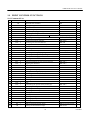
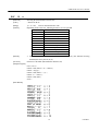
10. PRINT CONTROL FUNCTIONS
10.1 Commands List
Control Code
1
2
3
4
5
6
7
8
9
10
11
12
13
14
15
16
17
18
19
20
21
22
23
24
25
26
27
28
29
30
31
32
33
34
35
36
37
38
39
40
HT
LF
CR
ESC SP
ESC !
ESC %
ESC &
ESC *
ESC –
ESC 2
ESC 3
ESC =
ESC @
ESC D
ESC E
ESC G
ESC J
ESC R
ESC V
ESC a
ESC c3
ESC c4
ESC c5
ESC d
ESC i
ESC m
ESC p
ESC t
ESC u
ESC v
ESC {
ESC $
ESC ¥
GS
k
GS
w
GS
h
GS
H
GS
f
GS *
GS
/
Function
Code
Horizontal tab command
09H
Printing and paper feed
0DH
Print command
0DH
Setting the right space amount of the character
1BH 20H n
Collective specifying printing mode
1BH 21H n
Specifying/canceling download character set
1BH 25Hn
Defining download characters
1BH 26H 5 n m[a p1 p2 ... psxa]m-n+1
Specifying the bit image mode
1BH 2AH mn1n2[d]k
Specifying/canceling underline
1BH 2DH n
Specifying 1/6-inch line feed rate
1BH 32H
Setting line feed rate of minimum pitch
1BH 33H n
Data input control
1BH 3DH n
Initializing the Printer
1BH 40H
Setting horizontal tab position
1BH 44H [n]k00H
Specifying/canceling highlighting
1BH 45H n
Specifying/canceling double printing
1BH 47H n
Printing and feeding paper n/203 inch
1BH 4AH n
Selecting the international character set
1BH 52H n
1BH 56H n
Specifying/Canceling 90°-right- turned Characters
Aligning the characters
1BH 61H n
NOP
NOP
Enabling/disabling the panel switches
1BH 63H 35H n
Printing and feeding the paper by n lines
1BH 64H n
Activating auto cutter (Full cut)
1BH 69H
Activating auto cutter (Partial cut)
1BH 6DH
NOP
Selecting the character code table
1BH 74H n
NOP
Transmitting the printer status (Serial type)
1BH 76H n
Specifying/canceling the inverted characters
1BH 7BH n
Specifying the absolute positions
1BH 24H n1 n2
Specifying the relative positions
1BH 5C n1 n2
Printing the bar code
1DH 6BH n [“d”]k00H
1DH 77H n
Selecting the horizontal size (scale factor) of bar code
Selecting the height of the bar code
1DH 68H n
Selecting of print position of HRI code
1DH 48H n
Selecting the font of HRI code
1DH 66H n
Defining the download bit image
1DH2An1n2[d]n1xn2x8
Printing the download bit image
1DH 2FH m
42
Page
45
45
46
46
47
49
50
52
54
54
55
56
57
58
59
60
60
61
62
63
64
64
65
66
67
68
69
70
71
72
76
77
78
79
80
82
CITIZEN
CBM-202PC-04 User’s Manual
41
42
43
GS
GS
DC2
:
^
A
Starting/ending macro definition
Executing the macro
Selecting the Print drive system
1DH 3AH
1DH 5E n1n2 n3
12H 41H n
83
84
85
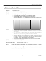
Notes: 1. In the table n, n1, n2, n3, m, a, s, p, and d denote the parameters for each command.
2. In the table, [ ]k denotes a repeat count of k-times.
3. In the table, ’ ’ denotes an ASCII character.
43
CITIZEN
CBM-202PC-04 User’s Manual
10.2
Command Details
10.2.1 Description of Items
XXXX
ALL
[Function]
Command Function
[Code]
A sequence of code constituting a command is represented in hexadecimal number for <
>H, binary number for <
>B, and decimal number for <
>, respectively; [
]k
represents a repeat count of k-times.
[Range]
Describes an argument value(Setting range) for the command.
[Outline]
Describes a command outline.
[Caution]
Describes a caution as required.
[Default]
Describes an initial value for the command when accompanied by an argument.
[See Also]
Describes the associated commands for use.
[Sample Program]
Describes a coding example in the Q-BASIC sample program.
This example is only for your reference and differs depending on the language used,
version, and so on.
For details, see the manual for the language used.
44
CITIZEN
CBM-202PC-04 User’s Manual
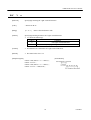
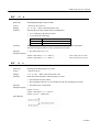
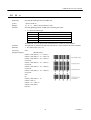
10.2.2 Details
HT
[Function]
Horizontal Tab Command
[Code]
<09>H
[Outline]
Shifts the printing position to the next horizontal tab position.
• Ignored when the next horizontal tab position has not been set.
[Caution]
• The horizontal tab position is set by ESC D.
• Initial setting of the horizontal tab position is each 8 characters in 9th, 17th, 25th,
columns.
[See Also]
ESC D
[Sample Program]
LPRINT "0123456789012345678901" ;
LPRINT CHR$ (&HA) ;
LPRINT CHR$ (&H9) + "AAA" ;
LPRINT CHR$ (&H9) + "BBB" ;
LPRINT CHR$ (&HA);
LPRINT CHR$ (&H1B) + "D" ;
LPRINT CHR$ (3) + CHR$ (7) + CHR$ (14) + CHR$ (0) ;
LPRINT CHR$ (&H9) + "AAA" ;
LPRINT CHR$ (&H9) + "BBB" ;
LPRINT CHR$ (&H9) + "CCC" + CHR$ (&HA) ;
[Print Results]
LF
[Function]
Printing and Paper Feed
[Code]
<0A>H
[Outline]
Prints data inside the input buffer and feeds lines based on the line feed amount having
been set.
• The head of the line becomes the next print starting position.
[See Also]
ESC 2, ESC 3
[Sample Program]
[Print Results]
LPRINT "AAA" + CHR$ (&HA) ;
LPRINT "BBB" + CHR$ (&HA) ;
LPRINT CHR$ (&HA) ;
LPRINT "CCC" + CHR$ (&HA) ;
45
CITIZEN
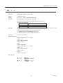
CBM-202PC-04 User’s Manual
CR
[Function]
Print Command
[Code]
<0D>H
[Outline]
1) When the function selecting terminal(Gate Array Pin 32) is HIGH.
This command is ignored.
2) When the function selecting terminal(Gate Array Pin 32) is LOW.
With data held inside the internal print buffer, printing and line feed are performed.
Without data inside the internal print buffer, however, no printing is performed.
LF
[See Also]
[Sample Program]
[Print Results]
LPRINT "AAA" + CHR$ (&HD) ;
LPRINT "BBB" + CHR$ (&HD) ;
LPRINT CHR$ (&HD) ;
LPRINT "CCC" + CHR$ (&HD) ;
ESC
SP
n
[Function]
Setting the right space amount of the character
[Code]
<1B>H<20>H<n>
[Range]
{ 0 ≤ n ≤ 20 }
[Outline]
The rightward space amount is set in dot unit (1/203 inch unit).
In the initial value, it is n=0.
[Caution]
The rightward space amount in double wide mode is made double of the set volume.
[Default]
n=0
Data is described in Hex code.
[Sample Program]
LPRINT CHR$ (&H1B) + "
" + CHR$ (0) ;
LPRINT "AAAAA" + CHR$ (&HA) ;
LPRINT CHR$ (&H1B) + "
" + CHR$ (1) ;
LPRINT "AAAAA" + CHR$ (&HA) ;
LPRINT CHR$ (&H1B) + "
" + CHR$ (12) ;
LPRINT "AAAAA" + CHR$ (&HA) ;
[Print Results]
46
CITIZEN
CBM-202PC-04 User’s Manual
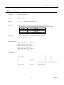
ESC
!
n
[Function]
Collective Specifying Printing Mode
[Code]
<1B>H<21>H<n>
[Range]
{ 0 ≤ n ≤ FF }
[Outline]
Printing mode is assigned.
Data is described in Hex code.
Each n bit indicates the following:
Value
Bit
0
1
2
3
4
5
6
7
[Caution]
Function
Character Font
Undefined
Undefined
High-lighting
Double height
Double width
Undefined
Underline
0
Font A
1
Font B
Canceled
Canceled
Canceled
Specified
Specified
Specified
Canceled
Specified
• With double height and double width being specified simultaneously, double wide and
double high characters are consisted.
• An underline is attached to the full character width, which, however, is not attached to
the part having been skipped by the horizontal tab. Neither is it attached to 90°
-right-turned characters.
• The underline width is as having been specified by <ESC - >. (The default setting is 1
dot width. )
• Specification with this command is invalid to Kanji, except specification and
cancellation of highlighting
• In case that double height character and normal character exist in same one line, the
layout of underline is consistent one.
[Default]
n=0
[See Also]
ESC E, ESC –
47
CITIZEN
CBM-202PC-04 User’s Manual
[Sample Program]
LPRINT CHR$ (&H1B) + " ! " + CHR$ (&H00) + "H" ;
LPRINT CHR$ (&H1B) + " ! " + CHR$ (&H01) + "H";
LPRINT CHR$ (&H1B) + " ! " + CHR$ (&H08) + "H";
LPRINT CHR$ (&H1B) + " ! " + CHR$ (&H10) + "H";
LPRINT CHR$ (&H1B) + " ! " + CHR$ (&H20) + "H";
LPRINT CHR$ (&H1B) + " ! " + CHR$ (&H80) + "H";
LPRINT CHR$ (&H1B) + " ! " + CHR$ (&HB9) + "H";
LPRINT CHR$ (&HA) ;
[Print Results]
48
CITIZEN
CBM-202PC-04 User’s Manual
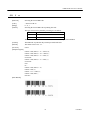
ESC
%
n
[Function]
Specifying/Canceling Download Character Set
[Code]
<1B>H<25>H<n>
[Range]
{ 0 ≤ n ≤ FF }
[Outline]
Specifying/canceling download characters. Further, only the lowest bit (n0) is valid for n.
The lowest bit (n0) indicates the following.
Data is described in Hex code.
n0
0
1
Function
Canceling download character set
Specifying download character set
[Caution]
Download characters and download bit images can not be defined simultaneously.
[Default]
n=0
[See Also]
ESC &
[Sample Program]
GOSUB SETCHR
DATA
6
LPRINT CHR$ (&H1B) + "%" + CHR$ (0) ;
DATA
&HFF, &H80, &H00
LPRINT "@A" + CHR$ (&HA) ;
DATA
&H80, &H80, &H00
LPRINT CHR$ (&H1B) + "%" + CHR$ (1) ;
DATA
&H80, &H80, &H00
LPRINT "@A" + CHR$ (&HA) ;
DATA
&H80, &H80, &H00
END
DATA
&HFF, &HFF, &HFF
SETCHR :
DATA
&HFF, &HFF, &HFF
LPRINT CHR$ (&H1B) + "&" ;
DATA
12
LPRINT CHR$ (3) + "@" + "A" ;
DATA
&HFF, &HFF, &HFF
FOR J=1 TO 2
DATA
&H80, &H07, &HF9
READ REP
DATA
&H80, &HFF, &HF9
LPRINT CHR$ (REP) ;
DATA
&H87, &HFE, &H01
FOR I=1 TO REP•3
DATA
&H9F, &H06, &H01
READ D
DATA
&HF8, &H06, &H01
LPRINTCHR$ (D) ;
DATA
&HF8, &H06, &H01
DATA
&H9F, &H06, &H01
DATA
&H87, &HFE, &H01
DATA
&H80, &HFF, &HF9
DATA
&H80, &H07, &HF9
DATA
&HFF, &HFF, &HFF
NEXT I
NEXT J
RETURN
[Print Results]
49
CITIZEN
CBM-202PC-04 User’s Manual
ESC
&
s
n
m [ a [ p ] s × a] m – n +1
[Function]
Defining Download Character
[Code]
<1B>H<26>H<s><n><m> [<a><p1><p2>· · · <ps×a>]m-n+1
[Range]
{s = 03}
{20 (Hex) ≤ n ≤ m ≤ 7E (Hex)}
{0 ≤ a ≤ 0C(Hex)} (Font A)
{0 ≤ a ≤ 0A(Hex)} (Font B)
[Outline]
Defines the font of download characters of alphanumeric characters.
• "s" indicates the number of bytes in vertical direction.
• "n" indicates the start character code and m the end character code. To define only one
character, set n=m.
• Character codes definable includes 95 ASCII codes in total between <20>H ~ <7E>H.
• "a" indicates the number of dots in horizontal direction for definition.
• "p" is the data to be defined, which indicate a pattern equal to "a" dot in horizontal
direction from the left end. The rest of the pattern on the right side is filled with space.
The rest of data to be defined is s x a.
• Download characters thus defined remain valid until redefinition, ESC @ execution,
GS * execution, or power OFF is practiced.
[Caution]
Download characters and download bit images can not be defined simultaneously.
Running this command clears the definition of the download bit image.
[Default]
Same as the internal character set
50
CITIZEN
CBM-202PC-04 User’s Manual
[Example]
Create each data bit by setting "1" for a printed dot and "0" for an unprinted dot.
[Sample Program]
[Print Results]
See Sample Program and Print Results for ESC % on Page 49.
51
CITIZEN
CBM-202PC-04 User’s Manual
ESC * m
n1
n2
[d]
k
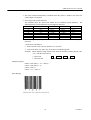
[Function]
Specifying the Bit Image Mode
[Code]
<1B>H<2A>H<m><n1><n2> [ <d> ] k
[Range]
{m= 0, 1, 32, 33 bit image mode (See the table below.)}
{0 ≤ n1 ≤ FF(Hex)}
{0 ≤ n2 ≤ 03(Hex)}
{0 ≤ d ≤ FF(Hex)}
{k = n1 + FF(Hex) × n2
(m = 0, 1)
{k = (n1+ FF(Hex) × n2) × 3} (m = 32, 33)
[Outline]
According to the number of dots specified in n1, n2, specify the bit image of mode n.
• The No. of dots printed is divided by 256, whose quotient is taken as n2 and residualas
n1.
• The total no. of dots printed in the bit image is equal to n1 + (256 x n2).
• When bit image data have been input in excess of dot position of one line(448 dots) ,
the excess data are discarded.
• d is bit image data, the bits subject to printing are taken as "1" and those not as "0".
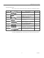
• The bit image modes specified by m are shown as follows:
m(Hex)
Mode
0
1
32
33
8-dot single density
8-dot double density
24-dot single density
24-dot double density
[Caution]
Vertical Direction
No. of Dots
Dot Density
8
67 DPI
8
67 DPI
24
203 DPI
24
203 DPI
Horizontal Direction
Dot Density
Max. No. of Dots
101 DPI
192
203 DPI
384
101 DPI
192
203 DPI
384
• When the values set in m (Bit image mode) are out of the above range, the data
following after n1 is processed as normal printing data.
• After completion of bit image printing, printer returns to normal data processing
mode.
52
CITIZEN
CBM-202PC-04 User’s Manual
[Example]
[Sample Program]
LPRINT CHR$ (&H1B) + "*" ;
LPRINT CHR$ (0) + CHR$ (20) + CHR$ (0) ;
IMG1 :
GOSUB IMG1
LPRINT
LPRINT CHR$ (&HA) ;
CHR$ (&HFF) ;
FOR I=1 TO 18
LPRINT CHR$ (&H1B) + "*" ;
LPRINT
LPRINT CHR$ (1) + CHR$ (20) + CHR$ (0) ;
GOSUB IMG1
LPRINT
LPRINT CHR$ (&HA) ;
CHR$ (&H85) ;
NEXT I
CHR$ (&HFF) ;
RETURN
LPRINT CHR$ (&H1B) + "*" ;
IMG2 ;
LPRINT CHR$ (32) + CHR$ (20) + CHR$ (0) ;
LPRINT
CHR$ (&HFF) ;
GOSUB IMG2
LPRINT
CHR$ (&HFF) ;
LPRINT CHR$ (&HA) ;
LPRINT
CHR$ (&HFF) ;
LPRINT CHR$ (&H1B) + "*" ;
FOR I=1 TO 18
LPRINT CHR$ (33) + CHR$ (20) + CHR$ (0) ;
LPRINT
CHR$ (&H80) ;
GOSUB IMG2
LPRINT
CHR$ (&H00) ;
LPRINT CHR& (&HA) ;
LPRINT
CHR$ (&H05) ;
END
NEXT I
LPRINT
CHR$ (&HFF) ;
LPRINT
CHR$ (&HFF) ;
LPRINT
CHR$ (&HFF) ;
RETURN
[Print Results]
53
CITIZEN
CBM-202PC-04 User’s Manual
ESC – n
[Function]
Specifying/ Canceling Underline
[Code]
<1B>H<2D>H<n>
[Range]
{0 ≤ n ≤ 02}
[Outline]
Specifying/canceling an underline.
Data is described in Hex code.
• Types of underlines by n value are shown below:
n (Hex)
0
1
2
[Caution]
Type
Canceling an underline.
Specifying an underline for 1-dot width.
Specifying an underline for 2-dots width.
• An underline is attached to the full character width. It is, however, not attached to the
part having been skipped by horizontal tab command.
• An underline is not attached to a 90° - right-turned characters.
• Specification/cancellation with this command is invalid to Kanji.
[See Also]
ESC !, FS –
[Sample Program]
LPRINT CHR$ (&H1B) + "–" + CHR$ (0) ;
LPRINT "AAAAA" ;
LPRINT CHR$ (&H1B) + "–" + CHR$ (1) ;
LPRINT "AAAAA" + CHR$ (&HA) ;
[Print Results]
ESC
2
[Function]
Specifying 1/6 inch line feed rate
[Code]
<1B>H<32>H
[Outline]
The line feed rate per line is specified by 1/6 inch.
[Sample Program]
[Print Results]
LPRINT "AAAAA" + CHR$ (&HA) ;
LPRINT CHR$ (&H1B) + "3" + CHR$ (0) ;
LPRINT "AAAAA" + CHR$ (&HA) ;
LPRINT CHR$ (&H1B) + "3" + CHR$ (50) ;
LPRINT "AAAAA" + CHR$ (&HA) ;
LPRINT CHR$ (&H1B) + "2" ;
LPRINT "AAAAA" + CHR$ (&HA) ;
LPRINT "AAAAA" ;
LPRINT CHR$ (&H1B) + "J" + CHR$ (100) ;
LPRINT "AAAAA" + CHR$ (&HA) ;
LPRINT "AAAAA" + CHR$ (&HA) ;
54
CITIZEN
CBM-202PC-04 User’s Manual
ESC
3
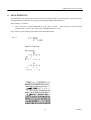
n
[Function]
Setting line feed rate of minimum pitch
[Code]
<1B>H<33>H<n>
[Range]
{0 ≤ n ≤ FF}
[Outline]
The line feed rate per line is specified by n/360 inch.
Since an actual mechanical pitch is 1/203 inch, it is internally converted approximate to
the value specified with this command.
[Default]
The initial value is n = 60 (1/6 inch) (18H), being 4.23 mm line feed rate.
[Sample Program]
Data is described in Hex code.
[Print Results]
See Sample Program and Print Results for ESC 2 on Page 54.
55
CITIZEN
CBM-202PC-04 User’s Manual
ESC
=
n
[Function]
Data Input Control
[Code]
<1B>H<3D>H<n>
[Range]
{0 ≤ n ≤ FF}
[Outline]
Selecting equipment in which data input from the host is effective.
Data is described in Hex code.
• Each bit of n indicates as follows:
Value
Bit
0
1
2
3
4
5
6
7
Equipment
Printer
Not defined
Not defined
Not defined
Not defined
Not defined
Not defined
Not defined
0
Invalid
1
Valid
• When the printer has not been selected, this printer abandons all the received data until
it is selected by this command.
[Caution]
• Even when the printer has not been selected, it can become BUSY state through
printer operation.
• When the printer is deselected, this printer discards all the data until it is selected with
this command.
[Default]
• The initial value of n is "1".
[Sample Program]
LPRINT "AAAAA" ;
LPRINT CHR$ (&H1B) + "=" + CHR$ (0) ;
LPRINT "aaaaa" + CHR$ (&HA) ;
LPRINT CHR$ (&H1B) + "=" + CHR$ (1) ;
LPRINT "AAAAA" + CHR$ (&HA) ;
[Print Results]
56
CITIZEN
CBM-202PC-04 User’s Manual
ESC
@
[Function]
Initializing the Printer
[Code]
<1B>H<40>H
[Range]
Clears data stored in the print buffer and brings various settings to the initial state
(Default state).
[Caution]
• Data inside the internal input buffer are not cleared.
• Dip switches setting are red once again.
[Sample Program]
[Print Results]
LPRINT CHR$ (&H1B) + " ! " + CHR$ (&H30) ;
LPRINT CHR$ (&H1B) + "V" + CHR$ (1) ;
LPRINT "AAA" + CHR$ (&HA) ;
LPRINT CHR$ (&H1B) + "@" ;
LPRINT "AAA" + CHR$ (&HA) ;
57
CITIZEN
CBM-202PC-04 User’s Manual
ESC
D
[n]
k
NUL
[Function]
Setting Horizontal Tab Position
[Code]
<1B>H<44>H [ <n> ] k<00>H
[Range]
{0 ≤ n ≤ FFH}
{0 ≤ k ≤ 20H}
[Outline]
Specifying a horizontal tab position.
Data is described in Hex code.
Data is described in Hex code.
• "n" indicates the no. of columns from the beginning to the horizontal tab position. At
this time, n= set position• 1 is to b e specified. For example, to set the position at 9th
column, n=8 is to be specified.
• k denotes the number of horizontal tab positions you want to set.
• The tab position is set at position where it is "character width x n" from the line
beginning. The character width, at this time, includes the rightward space amount.
In double wide characters, it is made double of the ordinary case.
• Tab positions can be specified are maximum 32. Specifying exceeding this is ignored.
• <n> k, which denotes a setting position, is input in the increasing order and ends at
<00> H.
• ESC D NUL clears all the set tab positions. Following clearing, horizontal tab
command is ignored.
[Caution]
When the data, <n> k, is equal to or smaller than its preceding data, <n> k-1, it is
assumed that tab setting is finished. If this is the case, the next data onward will be
processed as normal data.
When the data, <n> k, exceeds a 1-line print area, set the horizontal tab position,
assuming "Set column position = Maximum print column + 1."
The horizontal tab position does not change even if the character width is altered after
setting the horizontal tab position.
[Default]
• Initial value is specified for each eight characters(9th.17th.25th column) of ANK
characters.
[See Also]
HT
[Sample Program]
[Print Results]
See Sample Program and Print Results for HT on Page 45.
58
CITIZEN
CBM-202PC-04 User’s Manual
ESC
E
n
[Function]
Specifying/canceling highlighting
[Code]
<1B>H<45>H<n>
[Range]
{0 ≤ n ≤ FF}
[Outline]
Specifying/canceling the highlighting characters.
Data is described in Hex code.
• "n" is valid only for the lowest bit (n0).
• Control by the lowest bit (n0) is shown as follows:
n0
0
1
Type
Canceling highlighting.
Specifying highlighting.
• This is effective to all characters.
• Dot configuration of a highlighted character includes one extra dot added at its side.
[Caution]
• The print result of Double printing and highlight character printing is completely same.
[See Also]
ESC !
[Example]
[Sample Program]
LPRINT CHR$ (&H1B) + "E" + CHR$ (0) ;
LPRINT "AAABBB" + CHR$ (&HA) ;
LPRINT CHR$ (&H1B) + "E" + CHR$ (1) ;
LPRINT "AAABBB" + CHR$ (&HA) ;
[Print Results]
59
CITIZEN
CBM-202PC-04 User’s Manual
ESC
G
n
[Function]
Specifying/canceling Double Printing
[Code]
<1B>H<47>H<n>
[Range]
{0 ≤ n ≤ FF}
[Outline]
Specifying/canceling the double printing.
Data is described in Hex code.
• "n" is valid only for the lowest bit (n0).
• Control by n is shown as follows.
n0
0
1
Type
Canceling double printing.
Specifying double printing.
• This is effective to all characters.
[Caution]
• The print result of Double printing and highlight character printing is completely same.
[See Also]
ESC E
[Sample Program]
LPRINT CHR$ (&H1B) + "G" + CHR$ (0) ;
LPRINT "AAABBB" + CHR$ (&HA) ;
LPRINT CHR$ (&H1B) + "G" + CHR$ (1) ;
LPRINT "AAABBB" + CHR$ (&HA) ;
[Print Results]
ESC
J
n
[Function]
Printing and feeding paper n/203 inch
[Code]
<1B>H<4A>H<n>
[Range]
{0 ≤ n ≤ FF}
[Outline]
Prints data inside the print buffer and feeds paper by n/360 inch. Since an actual
mechanical pitch is 1/203 inch, it is internally converted approximate to the value
specified with this command.
Data is described in Hex code.
• Specified volume does not remain.
• The beginning of the line is to be considered as the next printing start position.
• Initial value is not defined.
[Sample Program]
[Print Results]
See Sample Program and Print Results for ESC 2 on Page 54.
60
CITIZEN
CBM-202PC-04 User’s Manual
ESC
R
n
[Function]
Selecting the International Character Set
[Code]
<1B>H<52>H<n>
[Range]
{0 ≤ n ≤ 0A)
[Outline]
Depending on the value of n, following character sets are specified.
Data is described in Hex code.
n(Hex)
0
1
2
3
4
5
6
7
8
9
A
Character Set
U.S.A.
France
Germany
U.K.
Denmark•
Sweden
Italy
Spain
Japan
Norway
Denmark•
[Default]
• The initial value of n indicates the character set specified by the function selecting
terminal(Gate Array Pin 39,42,43).
[See Also]
Character Code Table (International Character Set)
[Sample Program]
FOR I=0 TO 10
LPRINT CHR$ (&H1B) + "R" + CHR$ (I) ;
LPRINT " #$@[¥]^" ;
LPRINT CHR$ (&H60) + "{¥}• " ;
LPRINT "n=" + STR$ (I) ;
LPRINT CHR$ (&HA) ;
NEXT I
[Print Results]
61
CITIZEN
CBM-202PC-04 User’s Manual
ESC
V
n
[Function]
Specifying/Canceling 90°-right- turned Characters
[Code]
<1B>H<56>H<n>
[Range]
{0 ≤ n ≤ 1}
[Outline]
Specifying/canceling characters 90°-right- turned character.
Data is described in Hex code.
• "n" means the followings.
n (Hex)
0
1
Condition
Canceling 90°-right- turned Characters
Specifying 90°-right- turned Characters
[Caution]
• No underlines are attached to 90°-right- turned characters .
[Default]
• The initial value of n is "0".
[Sample Program]
[Print Results]
LPRINT CHR$ (&H1B) + "V" + CHR$ (0) ;
LPRINT "AAAAA" ;
LPRINT CHR$ (&H1B) + "V" + CHR$ (1) ;
LPRINT "AAAAA" + CHR$ (&HA) ;
62
CITIZEN
CBM-202PC-04 User’s Manual
ESC
a
n
[Function]
Aligning the characters
[Code]
<1B>H<61>H<n>
[Range]
{0 ≤ n ≤ 2}
[Outline]
All the printed data within one line are aligned in the specified position.
Data is described in Hex code.
• Depending on n value, positional alignment is carried out as in the table below:
n (Hex)
0
1
2
[Caution]
Position
Left end alignment
Centering
Right end alignment
• This is valid only when n is inputted at the beginning of line.
• The initial value of n is "0".
[Sample Program]
LPRINT CHR$ (&H1B) + "a" + CHR$ (0) ;
LPRINT "AAAAA" + CHR$ (&HA) ;
LPRINT CHR$ (&H1B) + "a" + CHR$ (1) ;
LPRINT "AAAAA" + CHR$ (&HA) ;
LPRINT CHR$ (&H1B) + "a" + CHR$ (2) ;
LPRINT "AAAAA" + CHR$ (&HA) ;
[Print Results]
63
CITIZEN
CBM-202PC-04 User’s Manual
ESC
c5
n
[Function]
Enabling/Disabling the Panel Switches
[Code]
<1B>H<63>H<35>H<n>
[Range]
{0 ≤ n ≤ FF}
[Outline]
Selecting the LF switch valid/invalid by LFSW(Pin 2).
Data is described in Hex code.
• "n" is valid only in the lowest bit (n0).
• "n" bit means the followings.
n0
0
1
Condition
LF SW valid.
LF SW invalid.
[Caution]
When the panel switch is disabled with this command, the LF switch is disabled.
Therefore, the paper cannot be fed by operating the LF switch.
[Default]
• The initial value of n is "0".
[Sample Program]
LPRINT CHR$ (&H1B) + "c5" + CHR$ (0) ; · · · · · · · · · · · · When enabling the LF switch
LPRINT CHR$ (&H1B) + "c5" + CHR$ (1) ; · · · · · · · · · · · · When disabling the LF switch
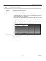
ESC
d
n
[Function]
Printing and Feeding the paper by n lines
[Code]
<1B>H<64>H<n>
[Range]
* {0 ≤ n ≤ FF}
[Outline]
Prints data inside the buffer and feeds paper by n lines.
Data is described in Hex code.
• Specified line does not remain.
• The beginning of the line is to be considered as the next printing start position.
[Default]
• The initial value is not defined.
[Sample Program]
LPRINT "AAAAA"
LPRINT CHR$ (&H1B) + "d" + CHR$ (2) ;
LPRINT "AAAAA" + CHR$ (&HA) ;
[Print Results]
64
CITIZEN
CBM-202PC-04 User’s Manual
ESC
i
(When Using Auto Paper Cutter)
[Function]
Full Cut
[Code]
<1B>H<69>H
[Outline]
Activating auto cutter unit (Full cut)
[Caution]
• This is valid only when n is inputted at the beginning of line.
• Prior to cutting the paper, feed the paper from the printing position to beyond the
paper cutting position of the cutter. Otherwise, the character just after print will remain
on this side of the cutter.
[Sample Program]
LPRINT "AAAAA" ;
LPRINT CHR$ (&H1B) + "J" ;
LPRINT CHR$ (150) ;
LPRINT CHR$ (&H1B) + "i" ;
LPRINT "AAAAA" ;
LPRINT CHR$ (&H1B) + "J" ;
LPRINT CHR$ (150) ;
LPRINT CHR$ (&H1B) + "i" ;
[Print Results]
65
CITIZEN
CBM-202PC-04 User’s Manual
ESC
m
(When Using Auto Paper Cutter)
[Function]
Partial Cut
[Code]
<1B>H<6D>H
[Outline]
Activating auto cutter unit (Partial cut)
[Caution]
• This is valid only when n is inputted at the beginning of line.
• Prior to cutting the paper, feed the paper from the printing position to beyond the
paper cutting position of the cutter. Otherwise, the character just after print will remain
on this side of the cutter.
[Sample Program]
LPRINT "AAAAA" ;
LPRINT CHR$ (&H1B) + "J" ;
LPRINT CHR$ (150) ;
LPRINT CHR$ (&H1B) + "m" ;
LPRINT "AAAAA" ;
LPRINT CHR$ (&H1B) + "J" ;
LPRINT CHR$ (150) ;
LPRINT CHR$ (&H1B) + "m" ;
[Print Results]
66
CITIZEN
CBM-202PC-04 User’s Manual
ESC
t
n
[Function]
Selecting the Character Code Table
[Code]
<1B>H<74>H<n>
[Range]
{0 ≤ n ≤ 1}
[Outline]
Selecting Page n on the character code table:
The character code table is selected depending on the value of n.
"n" means the followings.
Data is described in Hex code.
n (Hex)
0
1
[Default]
Condition
Page 0(IBM Character #2)
Page 1(Domestic Character)
The initial value of n is subject to the character set for the country specified by the
function selecting terminal (Gate Array Pin 39,42,43).
• When Japan is selected: Domestic characters
• When non-Japan is selected: IBM characters #2
[See Also]
Character Code Table
[Sample Program]
LPRINT CHR$ (&H1B) + "t" + CHR$ (0) ;
LPRINT " n=0
";
FOR C=&HB1 TO &HB5
LPRINT CHR$ (C) ;
NEXT C
LPRINT CHR$ (&HA) ;
LPRINT CHR$ (&H1B) + "t" + CHR$ (1) ;
LPRINT " n=1
";
FOR C=&HB1 TO &HB5
LPRINT CHR$ (C) ;
NEXT C
LPRINT CHR$ (&HA) ;
[Print Results]
67
CITIZEN
CBM-202PC-04 User’s Manual
ESC
v
(Serial Interface Only)
[Function]
Transmitting the printer status(Serial type)
[Code]
<1B>H<76>H
[Outline]
Current printer status is transmitted..
[Caution]
• Status sent out consists of 1 byte whose content is as in the table below.
• In DTR/DSR control, after receptible state of the host (DSR signal being in SPACE
state) is confirmed, only 1 byte is transmitted.
In XON/XOFF control, DSR signal state not being confirmed, only 1 byteis transmitted.
• In DTR/DSR control, when the host is in unreceptible state(DSR signal being in
MARK state), it waits until receptible state is created.
• In paper end (paper near end) status, this command may be unreceptible state due to
BUSY state.
Remarks. This command is valid only for serial interface model.
Value
Bit
0
1
2
3
4
5
6
7
Function
Not defined
Not defined
Paper end
Not defined
Not used
Not defined
Not defined
Not defined
0
1
With paper
Without paper
Fixed to 0
–
[Sample Program]
OPEN "COM1:N81NN" AS #1 ;
PRINT #1, CHR$ (&H1B) + "v" ;
A$ = INPUT$ (1, #1) ;
CLOSE #1
68
CITIZEN
CBM-202PC-04 User’s Manual
ESC
{
n
[Function]
Specifying/Canceling the Inverted Characters
[Code]
<1B>H<7B>H<n>
[Range]
{0 ≤ n ≤ FF}
[Outline]
Specifying/canceling inverted characters.
Data is described in Hex code.
• "n" is valid only for the lowest bit (n0).
• Bit n (n0) means the followings.
n0
0
1
[Caution]
Condition
Canceling inverted characters.
Specifying inverted characters.
• Inverted printing means printing the line at 180 °turned.
• This is valid only when this is specified at the beginning of a line.
[Default]
• The initial value of n is "0".
[Sample Program]
LPRINT CHR$ (&H1B) + "{" + CHR$ (0) ;
LPRINT "AAAAA" + CHR$ (&HA) ;
LPRINT "BBBBB" + CHR$ (&HA) ;
LPRINT CHR$ (&H1B) + "{" + CHR$ (1) ;
LPRINT "AAAAA" + CHR$ (&HA) ;
LPRINT "BBBBB" + CHR$ (&HA) ;
[Print Results]
69
CITIZEN
CBM-202PC-04 User’s Manual
ESC
$
n1
n2
[Function]
Specifying the Absolute Positions
[Code]
<1B>H<24>H<n1><n2>
[Range]
{0 ≤ n1 ≤ FF}
{0 ≤ n2 ≤ 1} Data is described in Hex code.
[Outline]
The printing start position is specified in the number of dots (1/203 inch unit) from the
beginning of line.
• The number of dots is divided by 256, whose quotient is taken as n2 and the residual
as n1.
• Therefore, the printing start position is equal to n1 + n2 x 256 from the beginning of
line..
[Caution]
• Specifying beyond the end of line is ignored.
[Default]
• The initial value is not specified.
[See Also]
ESC ¥
[Sample Program]
LPRINT CHR$ (&H1B) + "$" ;
LPRINT CHR$ (0) + CHR$ (0) + "A" ;
LPRINT CHR$ (&H1B) + "$" ;
LPRINT CHR$ (50) + CHR$ (0) + "B" ;
LPRINT CHR$ (&H1B) + "$" ;
LPRINT CHR$ (0) + CHR$ (1) + "C" ;
LPRINT CHR$ (&HA) ;
LPRINT CHR$ (&H1B) + "$" ;
LPRINT CHR$ (100) + CHR$ (0) + "A" ;
LPRINT CHR$ (&H1B) + "¥" ;
LPRINT CHR$ (&HC2) + CHR$ (&HFF) + "B" ;
LPRINT CHR$ (&HA) ;
[Print Results]
70
CITIZEN
CBM-202PC-04 User’s Manual
ESC
¥
n1
n2
[Function]
Specifying the Relative Positions
[Code]
<1B>H<5C>H<n1>< n2>
[Range]
{0 ≤ n1 ≤ FF}
{0 ≤ n2 ≤ FF}
[Outline]
Data is described in Hex code.
The printing start position is specified in the number of dots(1/203 inch unit) from the
current position.
• Rightward direction is taken as plus and leftward direction as minus.
• To specify N dot in minus (left) direction, use a complement of N for assignment.
• N dots = 65536 – N
• The number of dots is divided by 256, whose quotient is taken as n2 and the residual
as n1.
[Caution]
• Specifying exceeding the top of line or the end of line is ignored.
[Default]
• The initial value is not specified.
[See Also]
ESC $
[Sample Program]
[Print Results]
See Sample Program and Print Results for ESC $ on Page 70.
71
CITIZEN
CBM-202PC-04 User’s Manual
GS
k
n
[d]
k
NUL
[Function]
Printing the Bar Code
[Code]
<1D>H<6B>H<n> [ < d> ] k <00>H
[Range]
{0 ≤ n ≤ 7}
[Outline]
Specifying a type of bar code and printing bar codes.
Data are described in Hex code.
• The beginning of line is considered as the next printing start position.
• Depending on the value of n, the following bar cod e can be selected.
d indicates a character code to be printed and k indicates the number of character to be
printed.
n (Hex)
0
1
2
3
4
5
6
7
[Caution]
Bar Code System
UPC-A
UPC-E
JAN13 (EAN)
JAN 8 (EAN)
CODE 39
ITF
CODABAR (NW-7)
CODE 128
Maximum Columns
--------13
22
17
15
• When data being held in the print buffer, this command is ignored.
• Regardless of the specified feed pitch, this command feeds the paper to be required to
print a bar code.
• If the character code d cannot be printed in the respective bar code system, the bar
code so far will be printed, processing the subsequent data as normal data.
• When a bar code whose number of characters to be printed is fixed has been selected,
the number of characters k have to be always made equal to the number of characters
to be printed. (The bar code is not printed when not matching.)
• When the horizontal direction exceeds one line length, the excess part is not printed.
[Default]
• The initial value is not specified.
[Description of Bar Codes]
UPC-A
<For print examples, see Page 75.>
This bar code, consisting of numerals only, has a fixed length of 12 columns; a 11 columns
number entered from the host or application software plus a check column(12th column)
automatically calculated inside the printer. If the 12th-column numeral is sent from the
host, the entire bar code will be printed as it is.
72
CITIZEN
CBM-202PC-04 User’s Manual
UPC-E
This bar code, consisting of numerals only, has a fixed length of 8 columns; the first number
system character is "0" stationary. A 12 columns numeral entered from the host or
application software is compressed to 8 columns with a check column and printed. The
12th-column check column is automatically calculated inside the printer and sent from the
host, the entire bar code will be printed, compressed to 8 columns.
JAN-13(EAN) This bar code, consisting of numerals only, has a fixed length of 13 columns; a 12 columns
number entered from the host or application software plus a check column(13th column)
automatically calculated inside the printer. If the 13th-column numeral is sent from the
host, the entire bar code will be printed as it is.
JAN-8(EAN)
This bar code, consisting of numerals only, has a fixed length of 8 columns; a 7-columns
number entered from the host or application software plus a check column(8th column)
automatically calculated inside the printer. If the 8th-column numeral is sent from the host,
the entire bar code will be printed as it is.
CODE39
This bar code, consisting of uppercase alphabets and numerals, has a variable length of
column. A start/stop code "*" is automatically added by the printer. Available characters
include a space and "$, %, *, +, –, · , /, 0, 1, 2, 3, 4, 5, 6, 7, 8, 9," and uppercase alphabets.
ITF
This bar code, consisting of numerals only, has a variable length of even columns. If an
odd-column code is transferred, nothing will be printed.
CODABAR (NW-7)
This bar code, consisting of alphanumerals, has a variable length of column. Available
characters include "0, 1, 2, 3, 4, 5, 6, 7, 8, 9, A, B, D, D, $, +, –, . , /, :." A start/stop code is
required; any one of A, B, C, and D is used.
CODE128
• This bar code consists of all of 128 ASCII code characters and has a variable length of column.
This printer supports the code subsets A, B, and C. By prefixing a transfer code with any
one character of A, B, and C, you can select the code subset to start from. If not prefixed
with A, B, or C, the code subset B will be selected.
• The code subset A is the bar code consisting of standard uppercase alphabets, numerals,
symbols, and special codes.
• The code subset B is the bar code consisting of standard uppercase/lowercase alphabets,
numerals, symbols, control codes, and special codes.
• The code subset C is the bar code consisting of special characters and 100 kinds of
numbers ranging from 00 to 99.
73
CITIZEN
CBM-202PC-04 User’s Manual
• The check column automatically calculated inside the printer is added to the end of the
entered digits to be printed.
• Processing of the special characters
The characters above the ASCII code number 96 are considered special characters.
following lists the converted characters for entering these characters.
ASCII Code
96
97
98
99
100
101
102
Converted Character
80h
81h
82h
83h
84h
85h
86h
Subset Code
FNC 3
FNC 2
SHIFT
CODE C
CODE B
FNC 4
FNC 1
Subset Code B
FNC 3
FNC 2
SHIFT
CODE C
FNC 4
CODE A
FNC 1
The
Subset Code C
-N/A-N/A-N/A-N/ACODE B
CODE A
FNC 1
The following exemplifies a selection of the code subset as a method to utilize the special
characters.
<Selection of Code Subset>
• Initial selection: Enter any one character of A, B, and C.
• Conversion on the way: Enter any one character of 82h through 85h
Example) When initially testing with the code subset B, and then, printing the bar code,
"123," with the code subset A
• Input code
:
• Bar code data
:
B
TEST
<85>
123
<CODE B>TEST<CODE A>123
[Sample Program]
LPRINT CHR$ (&H1D) + "H" + CHR$ (2) ;
LPRINT CHR$ (&H1D) + "k" ;
LPRINT CHR$ (4) ;
LPRINT "123" + CHR$ (0) ;
[Print Results]
74
CITIZEN
CBM-202PC-04 User’s Manual
[Description of Bar Codes]
UPC-A, UPC-E, JAN-13 (EAN), JAN-8 (EAN), CODE39, ITF, CODABAR, CODE128
Type
UPC-A
Print Sample
Outline of Symbol
12-columns fixed-length bar code
consisting of numerals only
JAN-13
8-columns fixed-length bar code consisting
of numerals only. Abbreviated version of
UPC-A
13-columns fixed-length bar code
consisting of numerals only
JAN-8
8-columns fixed-length bar code consisting
of numerals only
UPC-E
CODE39
ITF
CODABAR
(NE-7)
CODE128
Variable-length bar code consisting of
alphabets and numerals. The start/stop
code "*" is automatically added.
Even-column variable-length bar code
consisting of numerals only
Variable-length bar code consisting of
alphanumerals. Any one of A, B, C, and
D is required as the start/stop code.
Variable -length bar code consisting of all
128 ASCII code characters.
Max. Columns
•
•
•
•
13
22
17
15
Printing is done depending on bar code specification type, number of print columns, bar
code height, width(Magnification), visible code presence, and bar code data specification.
75
CITIZEN
CBM-202PC-04 User’s Manual
GS
w
n
[Function]
Selecting the width of the Bar Code
[Code]
<1D>H <77>H<n>
[Range]
{2 ≤ n ≤ 4}
[Outline]
Selecting bar code width.
Data is described in Hex code.
n denotes the number of dots in fine element width.
[Default]
• The initial value of this width is "3".
[Sample Program]
LPRINT CHR$ (&H1D) + "h" + CHR$ (30) ;
LPRINT CHR$ (&H1D) + "w" + CHR$ (2) ;
GOSUB BC
LPRINT CHR$ (&H1D) + "h" + CHR$ (50) ;
LPRINT CHR$ (&H1D) + "w" + CHR$ (3) ;
GOSUB BC
LPRINT CHR$ (&H1D) + "h" + CHR$ (80) ;
LPRINT CHR$ (&H1D) + "w" + CHR$ (4) ;
GOSUB BC
END
BC :
LPRINT CHR$ (&H1D) + "k" ;
LPRINT CHR$ (4) ;
LPRINT "12" + CHR$ (0) ;
RETURN
[Print Results]
76
CITIZEN
CBM-202PC-04 User’s Manual
GS
h
n
[Function]
Selecting the Height of the Bar Code
[Code]
<1D>H<68>H<n>
[Range]
{1 ≤ n ≤ FF}
[Outline]
Selecting bar code height.
Data is described in Hex code.
n denotes the number of dots in the vertical direction.
[Default]
[Sample Program]
• The initial value of n is "162".
[Print Results]
See Sample Program and Print Results for GS w on page 76.
77
CITIZEN
CBM-202PC-04 User’s Manual
GS
H
n
[Function]
Selecting the Printing Position of HRI Code
[Code]
<1D>H<48>H<n>
[Range]
{0 ≤ n ≤ 3}
[Outline]
Selecting printing position of HRI codes in printing bar codes.
Data is described in Hex code.
• "n" means the followings.
n (Hex)
0
1
2
3
Printing Position
No printing
Above the bar code
Below the bar code
Both above and below the bar code
The HRI code refers to the bar code-turned characters so that you can read them.
[Caution]
The HRI code is printed in the font selected with GS f. Specify before the GS k command.
[Default]
• The initial value of n is "0".
[See Also]
GS f
[Sample Program]
[Print Results]
LPRINT CHR$ (&H1B) + "3" + CHR$ (5) ;
LPRINT CHR$ (&H1D) + "h" + CHR$ (50) ;
LPRINT CHR$ (&H1D) + "H" + CHR$ (0) ;
GOSUB BC
LPRINT CHR$ (&H1D) + "H" + CHR$ (1) ;
GOSUB BC
LPRINT CHR$ (&H1D) + "H" + CHR$ (2) ;
GOSUB BC
LPRINT CHR$ (&H1D) + "H" + CHR$ (3) ;
GOSUB BC
END
BC :
LPRINT CHR$ (&H1D) + "k" ;
LPRINT CHR$ (4) ;
LPRINT "12" + CHR$ (0) ;
LPRINT CHR$ (&HA) ;
RETURN
78
CITIZEN
CBM-202PC-04 User’s Manual
GS
f
n
[Function]
Selecting the font of HRI code
[Code]
<1D>H<66>H<n>
[Range]
n = 0, 1
[Outline]
Selecting the font of HRI code in printing bar code.
The type of font can be printed by selecting n is as follows.
n
0
1
Font
Font A
Font B
The HRI code refers to the bar code-turned characters so that you can read them.
[Caution]
The HRI code is printed at the position specified with GS h.
[Default]
The initial value of n is “0”.
[See Also]
GS H
[Sample Program]
LPRINT CHR$ (&H1D) + "h" + CHR$ (50) ;
LPRINT CHR$ (&H1D) + "H" + CHR$ (2) ;
LPRINT CHR$ (&H1D) + "f" + CHR$ (0) ;
GOSUB BC
LPRINT CHR$ (&H1D) + "f" + CHR$ (1) ;
GOSUB BC
END
BC :
LPRINT CHR$ (&H1D) + "k" ;
LPRINT CHR$ (4) ;
LPRINT "123" + CHR$ (0) ;
LPRINT CHR$ (&HA) ;
RETURN
[Print Results]
79
CITIZEN
CBM-202PC-04 User’s Manual
GS
*
n1
n2
[d]
n1 × n2 × 8
[Function]
Defining the Download Bit Image
[Code]
<1D>H<2A>H<n1><n2> [ < d > ] n1 × n2 × 8
[Range]
{1 ≤ n1 ≤ FF}
{1 ≤ n2 ≤ 30}
{n1 × n2 ≤ 51F}
[Outline]
Data is described in Hex code.
Defines downloading bit images of the number of dots specified by n1/n2.
• The numbers of dots are n1 x 8 in horizontal direction and n2 x 8 in vertical direction.
• d indicates bit image data.
• The download bit image thus defined remains effective until redefinition, ESC @
execution, ESC &, or power OFF takes place.
[Caution]
• A download character and a download bit image can not be defined simultaneously.
With this command executed, defined content of a download character is cleared.
• Relations between the bit image data and the dot defined are shown below:
• If a download bit image is defined with this command while it is being printed (GS /),
printing operation may become unstable (fluctuating print pitch).
[See Also]
GS /
80
CITIZEN
CBM-202PC-04 User’s Manual
[Sample Program]
[Print Results]
GOSUB IMG
LPRINT CHR$ (&H1D) + "/" + CHR$ (0) ;
LPRINT CHR$ (&H1D) + "/" + CHR$ (1) ;
LPRINT CHR$ (&H1D) + "/" + CHR$ (2) ;
LPRINT CHR$ (&H1D) + "/" + CHR$ (3) ;
END
IMG :
n 1 = 10 : n 2= 5
LPRINT CHR$ (&H1D) + "*" ;
LPRINT CHR$ (n1) + CHR$ (n2) ;
FOR J=1 TO n1 * 8
FOR I=1 TO n2
LPRINT CHR$ (J) ;
NEXT I
NEXT J
RETURN
81
CITIZEN
CBM-202PC-04 User’s Manual
GS
/
m
[Function]
Printing the Download, Bit Image
[Code]
<1D>H<2F>H<m>
[Range]
{0 ≤ m ≤ 03}
[Outline]
Prints download bit image in a mode specified by m.
Data is described in Hex code.
• Modes can be selected by m are shown below.
m
Mode Name
0
1
2
3
Normal mode
Double wide mode
Double height mode
Double wide/double height mode
[Caution]
Dot Density in
Vertical Direction
203 DPI
203 DPI
101 DPI
101 DPI
Dot Density in
Horizontal Direction
203 DPI
101 DPI
203 DPI
101 DPI
• When data exist inside the print buffer, this command is ignored.
• When a download bit image has not been defined, this command is ignored.
• A portion of a download bit image exceeding one line length is not printed.
• A download character and a download bit image cannot be defined simultaneously.
• If a download bit image data is defined while it is being printed with this command,
printing operation may become unstable (fluctuating print pitch).
[Default]
• The initial value is not specified.
[See Also]
GS *
[Sample Program]
[Print Results]
See Sample Program and Print Results for GS * on Page 80.
82
CITIZEN
CBM-202PC-04 User’s Manual
GS
:
[Function]
Starting / Ending Macro Definition
[Code]
<1D>H<3A>H
[Outline]
Specifying starting / ending macro definition.
Means termination when received while defining a macro.
[Caution]
Maximum content available for macro definition is 2048 bytes. A portion exceeding 2048
bytes is not defined.
• Even with ESC @ (Initialization of the printer) having been executed, defined content
is not cleared. Therefore, it is possible to include ESC @ into the content of macro
definition.
• Normal printing operation is carried out even while in macro definition
[Default]
• Initially, Macro is not specified.
[See Also]
GS ^
[Sample Program]
[Print Results]
LPRINT CHR$ (&H1D) + " : " ;
LPRINT "+ – – – +" + CHR$ (&HA) ;
LPRINT "|
|" + CHR$ (&HA) ;
LPRINT "+ – – – +" + CHR$ (&HA) ;
LPRINT CHR$ (&H1D) + " : " ;
LPRINT CHR$ (&H1D) + " ^ " ;
LPRINT CHR$ (2) + CHR$ (10) ;
LPRINT CHR$ (0) ;
83
CITIZEN
CBM-202PC-04 User’s Manual
GS
^
n1
n2
n3
[Function]
Executing the Macro
[Code]
<1D>H<5E>H<n1><n2><n3>
[Range]
{0 ≤ n1 ≤ FF}
{0 ≤ n2 ≤ FF}
{0 ≤ 3 ≤ 1} Data is described in Hex code.
[Outline]
Executing contents defined in macro.
• "n1 ~ n3" indicate as follows:
n1 : The number of times of macro execution
n2 : Waiting time on macro execution
Waiting time of n2 ×100ms is given for every execution.
n3 : Macro execution mode
n3
0
1
Mode
Continuous execution
Execution by LFSW(Pin 2)
Continuous execution: The Macro is executed n1 times continuously at the time intervals
specified by n2.
Execution by LFSW:
[Caution]
After waiting for lapse of time specified by n2, the Alarm LED
flickers and the LF switch is waited to be pressed. When it is
pressed, the macro is executed once.
This action is repeated n1 times.
• When this command is received while in macro definition, suspension of macro
definition is indicated. At this time, the defined content is cleared.
• No execution takes place when macro is held undefined or n1=0.
• While in macro execution with n3=1, paper feed with the LFSW (Pin 2) is not available.
[Default]
• Initially, this command is not specified.
[See Also]
GS :
[Sample Program]
[Print Results]
See Sample Program and Print Results for GS : on Page 83.
84
CITIZEN
CBM-202PC-04 User’s Manual
DC2
A
n
[Function]
Selecting the Print drive system
[Code]
<12>H<41>H<n>
[Range]
{0 ≤ n ≤ FF}
[Outline]
Selecting the Fixed division system or the Variable division system.
• "n" is valid only for the lowest bit (n0).
n0
0
1
[Default]
Print Drive System
Fixed Division Number System
Variable Division Number System
The initial value of n is specified by the function selecting terminal (Gate Array Pin37) .
85
CITIZEN
CBM-202PC-04 User’s Manual
11. CHARACTER CODE TABLE
11.1 International
86
CITIZEN
CBM-202PC-04 User’s Manual
11.2 Domestic
87
CITIZEN
CBM-202PC-04 User’s Manual
11.3 International Character Set
Country
88
CITIZEN