1
Si39-303
Design, Installation & Testing Instruction
R410A Heat Pump 50Hz
RXYQ5MY1B
RXYQ8MY1B
RXYQ10MY1B
RXYQ12MY1B
RXYQ14MY1B
RXYQ16MY1B
RXYQ18MY1B
RXYQ20MY1B
RXYQ22MY1B
RXYQ24MY1B
RXYQ26MY1B
RXYQ28MY1B
RXYQ30MY1B
RXYQ32MY1B
RXYQ34MY1B
RXYQ36MY1B
RXYQ38MY1B
RXYQ40MY1B
RXYQ42MY1B
RXYQ44MY1B
RXYQ46MY1B
RXYQ48MY1B
Preface
This system is a modular zone controllable air conditioning system of great sophistication which is capable of assembly in a
variety of different configurations. It would, however, be no exaggeration to say that the full potential of the systemÕs functions
can only be achieved in combination with the skills of those involved in the design of the equipment itself and those
responsible for the installation work.
As the move towards intelligent buildings has gathered momentum, so we have also been seeing ever more a growing
demand for a wider range of independently controllable building related functions.
Against this background there have also quite naturally been calls for the development of more distributed types of air
conditioning systems while at the same time taking full account of the need to use energy economically by demand matching
in view of the huge annual increases in the demand for electric power seen in recent years.
We have therefore prepared this installation manual to enable installation work to be handled confidently on the basis of a
clear understanding of the special features of this system. We have paid particular attention to points of difference in
installation procedure between this system and the more traditional package and room air conditioning system.
The manual is designed specifically to cater for those supervising installation work and concentrates on those products which
are currently on the market. Essential points which need to be taken into consideration when designing an appropriate
configuration for the system and in each of the separate installation processes have also been included.
We have also added a section covering problems which have arisen in connection with installation work undertaken to date in
an attempt to prevent the recurrence of the same problems.
Please be sure to read this manual thoroughly before starting installation work in order to ensure that all such work is carried
out with maximum efficiency and to maximum effect.
The following technical documents are also available from Daikin. Please use these documents together with this manual to
conduct efficient servicing.
Service Manual VRVII R410A Heat Pump 50Hz Series Si39-303 April. 2003.
July, 2003
After Sales Service Division
Si39-303
System
R410A PLUS Series
Part 1 General Information ........................................................... 1
1. Product Outline .......................................................................................2
1.1
1.2
1.3
1.4
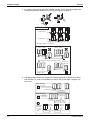
Model Names of Indoor/Outdoor Units.....................................................2
External Appearance................................................................................3
Combination of Outdoor Units ..................................................................5
Model Selection........................................................................................6
2. Points to Bear in Mind at the System Design..........................................8
2.1 Points Relating to the Performance of the Air Conditioning Units ............8
2.2 The Installation is of Vital Importance ......................................................9
2.3 Striking a Balance between System Installation and
General Construction Work (Comprehensive Flow Chart) .....................10
2.4 Points to Bear in Mind when Preparing the Contract Drawings .............11
3. Installation .............................................................................................14
3.1 Step by Step Installation Procedure .......................................................14
3.2 Work Involved in Individual Operations
and Points to be Borne in Mind ..............................................................15
4. Test Operation ......................................................................................62
4.1
4.2
4.3
4.4
Procedure and Outline ...........................................................................62
Operation When Power is Turned On ....................................................65
Outdoor Unit PC Board Layout...............................................................66
Field Setting ...........................................................................................67
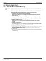
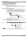
5. Caution for Refrigerant Leaks .............................................................102
5.1 Caution for Refrigerant Leaks ..............................................................102
6. Hand Over to Customer ......................................................................105
6.1 Operational Steps.................................................................................105
7. Appendix .............................................................................................106
7.1
7.2
7.3
7.4
7.5
7.6
7.7
7.8
7.9
7.10
7.11
7.12
Operating Noise of Indoor Units ...........................................................106
Piping Installation Point ........................................................................108
Allowable Piping Length .......................................................................110
Refrigerant branch kit selection............................................................113
Pipe size selection................................................................................115
How to calculate the additional refrigerant to be charged ....................117
Outdoor Unit Multi Connection Piping Kit .............................................119
REFNET Pipe Connections for VRV II R410A Series ..........................126
VRV Inspection Sheet ..........................................................................129
Piping System Diagrams ......................................................................134
Wiring Diagrams...................................................................................138
Bad Examples and Good Examples in Installation...............................144
Part 2 Installation Manual ........................................................ 153
1. Introduction .........................................................................................155
1.1 Combination .........................................................................................155
Table of Contents
i
Si39-303
1.2
1.3
1.4
1.5
1.6
2.
3.
4.
5.
6.
Standard Operation Limit .....................................................................156
Standard Supplied Accessories ...........................................................156
Option Accessory .................................................................................157
Technical Specifications ......................................................................158
Electrical Specifications........................................................................160
Main Components ...............................................................................161
Selection of Location...........................................................................162
Inspecting and Handling the Unit ........................................................164
Unpacking and Placing the Unit ..........................................................165
Refrigerant Piping ...............................................................................167
6.1
6.2
6.3
6.4
6.5
6.6
Selection of Piping Material..................................................................167
Connecting the Refrigerant Piping .......................................................168
Example of Connection ........................................................................173
Leak test and Vacuum Drying ..............................................................175
Pipe Insulation......................................................................................177
Additional refrigerant charge ................................................................178
7. Field Wiring .........................................................................................180
7.1
7.2
7.3
7.4
Optional Parts Cool / Heat Selector .....................................................180
Power Circuit and Cable Requirements ...............................................181
General.................................................................................................182
Examples..............................................................................................183
8. Before Operation.................................................................................191
8.1 Checks Before Initial Start-up...............................................................191
8.2 Test Run...............................................................................................192
9. Caution for Refrigerant Leaks .............................................................194
9.1 Caution for Refrigerant Leaks ..............................................................194
Part 3 Operation Manual ........................................................... 197
1. Safety Cautions...................................................................................199
2. What to Do Before Operation..............................................................202
3. Remote Controller and Changeover Switch:
Name and Function of Each Switch and Display ................................203
4. Warning...............................................................................................205
4.1 Never Do the Following ........................................................................205
5. Operation Range.................................................................................206
6. Operation Procedure...........................................................................207
6.1 Cooling, Heating and Fan Only Operation ...........................................207
6.2 Program Dry Operation ........................................................................209
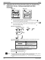
6.3 Adjusting the Air Flow Direction (Only for Double-flow,
Multi-flow, Corner, Ceiling-suspended and Wall-mounted) ..................210
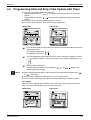
6.4 Programming Start and Stop of the System with Timer .......................211
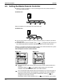
6.5 Setting the Master Remote Controller ..................................................212
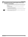
6.6 Precautions for group control system or
two remote controller control system....................................................213
7. Optimum Operation.............................................................................214
8. Following Symptoms are not Air Conditioner Troubles .......................215
8.1
8.2
8.3
8.4
ii
The System does not operate ..............................................................215
Cool/Heat cannot be Changed Over ....................................................215
Fan Operation is Possible, but Cooling and Heating do not Work .......215
The Fan Strength does not Correspond to the Setting.........................215
Table of Contents
Si39-303
8.5
8.6
8.7
8.8
8.9
8.10
8.11
8.12
The Fan Direction does not Correspond to the Setting ........................215
White Mist comes out of a Unit.............................................................216
Noise of Air Conditioners......................................................................216
Dust comes out of the Unit ...................................................................216
The Units can Give off Odours .............................................................216
The Outdoor Unit Fan does not Spin....................................................216
The Display Shows "88" .......................................................................217
The Compressor in the Outdoor Unit does not
Stop after a Short Heating Operation ...................................................217
8.13 The Inside of an Outdoor Unit is
Warm even when the Unit has stopped ...............................................217
9. Troubleshooting ..................................................................................218
Part 4 Precautions for New Refrigerant (R410A) ..................... 221
1. Precautions for New Refrigerant (R410A)...........................................222
1.1 Outline ..................................................................................................222
1.2 Refrigerant Cylinders............................................................................224
1.3 Service Tools........................................................................................225
Table of Contents
iii
Si39-303
iv
Table of Contents
Si39-303
Part 1
General Information
1. Product Outline .......................................................................................2
1.1
1.2
1.3
1.4
Model Names of Indoor/Outdoor Units.....................................................2
External Appearance................................................................................3
Combination of Outdoor Units ..................................................................5
Model Selection........................................................................................6
2. Points to Bear in Mind at the System Design..........................................8
2.1 Points Relating to the Performance of the Air Conditioning Units ............8
2.2 The Installation is of Vital Importance ......................................................9
2.3 Striking a Balance between System Installation
and General Construction Work (Comprehensive Flow Chart) ..............10
2.4 Points to Bear in Mind when Preparing the Contract Drawings .............11
3. Installation .............................................................................................14
3.1 Step by Step Installation Procedure .......................................................14
3.2 Work Involved in Individual Operations
and Points to be Borne in Mind ..............................................................15
4. Test Operation ......................................................................................62
4.1
4.2
4.3
4.4
Procedure and Outline ...........................................................................62
Operation When Power is Turned On ....................................................65
Outdoor Unit PC Board Layout...............................................................66
Field Setting ...........................................................................................67
5. Caution for Refrigerant Leaks .............................................................102
5.1 Caution for Refrigerant Leaks ..............................................................102
6. Hand Over to Customer ......................................................................105
6.1 Operational Steps.................................................................................105
7. Appendix .............................................................................................106
7.1
7.2
7.3
7.4
7.5
7.6
7.7
7.8
7.9
7.10
7.11
7.12
General Infomation
Operating Noise of Indoor Units ...........................................................106
Piping Installation Point ........................................................................108
Allowable Piping Length .......................................................................110
Refrigerant branch kit selection............................................................113
Pipe size selection................................................................................115
How to calculate the additional refrigerant to be charged ....................117
Outdoor Unit Multi Connection Piping Kit .............................................119
REFNET Pipe Connections for VRV II R410A Series ..........................126
VRV Inspection Sheet ..........................................................................129
Piping System Diagrams ......................................................................134
Wiring Diagrams...................................................................................138
Bad Examples and Good Examples in Installation...............................144
1
Product Outline
Si39-303
1. Product Outline
1.1
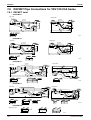
Model Names of Indoor/Outdoor Units
Indoor Units
Type
Model Name
Power Supply
Ceiling mounted
cassette type
(Double flow)
FXCQ
20M
25M
32M
40M
50M
63M
80M
—
125M
—
—
Ceiling mounted
cassette type
(Multi flow)
600×600
FXZQ
20M
25M
32M
40M
50M
—
—
—
—
—
—
Ceiling mounted
cassette type
(Multi flow)
FXFQ
—
25M
32M
40M
50M
63M
80M
—
—
FXKQ
—
25M
32M
40M
—
63M
—
—
—
FXSQ
20M
25M
32M
40M
50M
63M
80M
100M 125M
—
—
FXMQ
—
—
—
40M
50M
63M
80M
100M 125M 200M 250M
FXHQ
—
—
32M
—
—
63M
—
100M
—
—
—
FXAQ
20M
25M
32M
40M
50M
63M
—
—
—
—
—
FXLQ
20M
25M
32M
40M
50M
63M
—
—
—
—
—
FXNQ
20M
25M
32M
40M
50M
63M
—
—
—
—
—
Ceiling mounted
cassette corner
Ceiling mounted
built-in type
Ceiling mounted
duct type
Ceiling
suspended type
Wall mounted
type
Floor standing
type
Concealed Floor
standing type
100M 125M
—
—
VE
Outdoor Units (Inverter Series)
Series
Inverter Heat Pump
RXYQ
5M
8M
10M
12M
Series
2
14M
16M
18M
20M
22M
24M
26M
RXYQ
28M
30M
32M
34M
36M
38M
Y1B
Power
Supply
Model Name
Inverter Heat Pump
VE:
Y1B:
Power
Supply
Model Name
40M
42M
44M
46M
48M
Y1B
1φ, 220~240V, 50Hz, 1φ, 220V, 60Hz
3φ, 380~415V, 50Hz
General Information
Si39-303
1.2
Product Outline
External Appearance
1.2.1 Indoor Units
Ceiling mounted cassette type (Double flow)
FXCQ20M
FXCQ25M
FXCQ32M
FXCQ40M
FXCQ50M
FXCQ63M
FXCQ80M
FXCQ125M
Ceiling mounted duct type
FXMQ40M
FXMQ50M
FXMQ63M
FXMQ80M
FXMQ100M
FXMQ125M
FXMQ200M
FXMQ250M
FXMQ40~125M
FXMQ200 · 250M
Ceiling mounted cassette type
(Multi flow) 600×600
FXZQ20M
FXZQ25M
FXZQ32M
FXZQ40M
FXZQ50M
Ceiling mounted cassette type (Multi flow)
FXFQ25M
FXFQ32M
FXFQ40M
FXFQ50M
FXFQ63M
FXFQ80M
FXFQ100M
FXFQ125M
Ceiling mounted cassette corner type
FXKQ25M
FXKQ32M
FXKQ40M
FXKQ63M
Ceiling mounted built-in type
FXSQ20M
FXSQ25M
FXSQ32M
FXSQ40M
FXSQ50M
FXSQ63M
FXSQ80M
FXSQ100M
FXSQ125M
General Information
Ceiling suspended type
FXHQ32M
FXHQ63M
FXHQ100M
Wall mounted type
FXAQ20M
FXAQ25M
FXAQ32M
FXAQ40M
FXAQ50M
FXAQ63M
Floor standing type
FXLQ20M
FXLQ25M
FXLQ32M
FXLQ40M
FXLQ50M
FXLQ63M
Concealed floor standing type
FXNQ20M
FXNQ25M
FXNQ32M
FXNQ40M
FXNQ50M
FXNQ63M
3
Product Outline
Si39-303
1.2.2 Outdoor Units
RXYQ5M
RXYQ8M,10M
RXYQ12M,14M,16M
RXYQ18M, 20M
5HP
8,10HP
12,14,16HP
18, 20HP
RXYQ22M, 24M, 26M
RXYQ28M, 30M, 32M
22, 24, 26HP
28, 30, 32HP
RXYQ34M, 36M
RXYQ38M, 40M, 42M
34, 36HP
38, 40, 42HP
RXYQ44M, 46M, 48M
44, 46, 48HP
4
General Information
Si39-303
1.3
Product Outline
Combination of Outdoor Units
System Capacity Number of units
Module
5
8
10
12
14
16
●
5HP
8HP
1
1
10HP
12HP
1
1
14HP
16HP
1
1
18HP
20HP
2
2
22HP
24HP
2
2
●
●
26HP
28HP
2
2
●
30HP
32HP
2
2
34HP
36HP
3
3
●●
●●
38HP
40HP
3
3
●
●
42HP
44HP
3
3
●
46HP
48HP
3
3
●
●
●
●
●
●
●
●●
●
●
●
●
●
●
●
●●
●
●
●
●
●
●
●●
●●
●
●
●●
●●●
★18~48HP are realized by combining 8, 10, 12, 14 and 16HP.
General Information
5
Product Outline
1.4
Si39-303
Model Selection
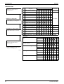
VRV II Heat Pump Series
Connectable indoor units number and capacity
5HP
8HP
10HP
12HP
14HP
16HP
System name
HP
RXYQ5M
RXYQ8M
RXYQ10M
RXYQ12M
RXYQ14M
RXYQ16M
Outdoor unit 1
RXYQ5M
RXYQ8M
RXYQ10M
RXYQ12M
RXYQ14M
RXYQ16M
Outdoor unit 2
–
–
–
–
–
–
Outdoor unit 3
–
–
–
–
–
–
Total number of connectable indoor units
8
13
16
19
20
20
Total capacity of connectable indoor units (kW)
7.0~18.2
11.2~29.1
14.0~36.4
16.8~43.6
20.0~52.0
22.5~58.5
HP
System name
18HP
20HP
22HP
24HP
26HP
28HP
RXYQ18M
RXYQ20M
RXYQ22M
RXYQ24M
RXYQ26M
RXYQ28M
Outdoor unit 1
RXYQ8M
RXYQ10M
RXYQ10M
RXYQ10M
RXYQ10M
RXYQ12M
Outdoor unit 2
RXYQ10M
RXYQ10M
RXYQ12M
RXYQ14M
RXYQ16M
RXYQ16M
Outdoor unit 3
–
–
–
–
–
–
Total number of connectable indoor units
20
20
22
32
32
32
Total capacity of connectable indoor units (kW)
25.2~65.5
28.0~72.8
30.8~80.0
34.0~88.4
36.5~94.9
39.3~102.1
30HP
32HP
34HP
36HP
38HP
40HP
System name
HP
RXYQ30M
RXYQ32M
RXYQ34M
RXYQ36M
RXYQ38M
RXYQ40M
Outdoor unit 1
RXYQ14M
RXYQ16M
RXYQ10M
RXYQ10M
RXYQ10M
RXYQ10M
Outdoor unit 2
RXYQ16M
RXYQ16M
RXYQ10M
RXYQ10M
RXYQ12M
RXYQ14M
Outdoor unit 3
–
–
RXYQ14M
RXYQ16M
RXYQ16M
RXYQ16M
Total number of connectable indoor units
32
32
34
36
38
40
Total capacity of connectable indoor units (kW)
42.5~110.5
45.0~117.0
48.0~124.8
50.5~131.3
53.3~138.5
56.5~146.9
42HP
44HP
46HP
48HP
System name
HP
RXYQ42M
RXYQ44M
RXYQ46M
RXYQ48M
Outdoor unit 1
RXYQ10M
RXYQ12M
RXYQ14M
RXYQ16M
Outdoor unit 2
RXYQ16M
RXYQ16M
RXYQ16M
RXYQ16M
Outdoor unit 3
RXYQ16M
RXYQ16M
RXYQ16M
RXYQ16M
Total number of connectable indoor units
40
40
40
40
Total capacity of connectable indoor units (kW)
59.0~153.4
61.8~160.6
65.0~169.0
67.5~175.5
6
General Information
Si39-303
Product Outline
Connectable indoor unit
Type
Model Name
Power Supply
Ceiling mounted
cassette type
(Double flow)
FXCQ
20M
25M
32M
40M
50M
63M
80M
—
125M
—
—
Ceiling mounted
cassette type
(Multi flow)
600×600
FXZQ
20M
25M
32M
40M
50M
—
—
—
—
—
—
Ceiling mounted
cassette type
(Multi flow)
FXFQ
—
25M
32M
40M
50M
63M
80M
—
—
FXKQ
—
25M
32M
40M
—
63M
—
—
—
FXSQ
20M
25M
32M
40M
50M
63M
80M
100M 125M
—
—
FXMQ
—
—
—
40M
50M
63M
80M
100M 125M 200M 250M
FXHQ
—
—
32M
—
—
63M
—
100M
—
—
—
FXAQ
20M
25M
32M
40M
50M
63M
—
—
—
—
—
FXLQ
20M
25M
32M
40M
50M
63M
—
—
—
—
—
FXNQ
20M
25M
32M
40M
50M
63M
—
—
—
—
—
Ceiling mounted
cassette corner
Ceiling mounted
built-in type
Ceiling mounted
duct type
Ceiling
suspended type
Wall mounted
type
Floor standing
type
Concealed Floor
standing type
100M 125M
—
—
VE
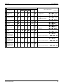
Indoor unit capacity
New refrigerant model code
Selecting model capacity
Equivalent output
P20
type
2.2
kW
P25
type
2.8
kW
P32
type
3.5
kW
P40
type
4.5
kW
P50
type
5.6
kW
P63
type
7.0
kW
P80
type
9.0
kW
P100
type
11.2
kW
P125
type
14.0
kW
P200
type
22.4
kW
P250
type
28.0
kW
0.8HP
1HP
1.25HP
1.6HP
2.0HP
2.5HP
3.2HP
4HP
5HP
8HP
10HP
Use the above tables to determine the capacities of indoor units to be connected. Make sure the
total capacity of indoor units connected to each outdoor unit is within the specified value (kW).
! The total capacity of connected indoor units must be within a range of 50 to 130% of the
rated capacity of the outdoor unit.
! In some models, it is not possible to connect the maximum number of connectable indoor
units. Select models so the total capacity of connected indoor units conforms to the
specification.
General Information
7
Points to Bear in Mind at the System Design
Si39-303
2. Points to Bear in Mind at the System Design
2.1
Points Relating to the Performance of the Air
Conditioning Units
A number of points need to be borne in mind at the system design stage in order to ensure the mechanical
efficiency of the air conditioning units.
1. Path of refrigerant piping between outdoor and indoor units, height difference and pipe length.
! Path of refrigerant piping should be determined such that length of piping is kept to a minimum.
! Piping should be kept within permissible limits in terms of length and height difference.
2. Positioning of outdoor unit
! Position such that maintenance and repairs can be carried out. (leave room for servicing)
! Avoid reduction of airflow and short circuiting
! Avoid reduction of airflow and short circuiting
3. Positioning of indoor unit
! Position such that maintenance and repairs can be carried out. (inspection port positions and size
check)
! Avoid short circuiting
! Ensure sufficient drain pipe gradient (need for drain-up kit etc.)
! In the case of a ceiling mounted type make sure ceiling depth is sufficient (need for high performance
filter, etc.)
8
General Information
Si39-303
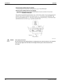
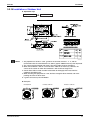
2.2
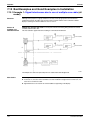
Points to Bear in Mind at the System Design
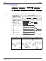
The Installation is of Vital Importance
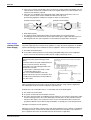
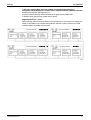
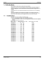
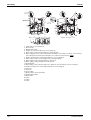
The analysis of major installation problems experienced during the year of 1988 is shown below;
How these installation problems affect an equipment are shown below:
General Information
9
Points to Bear in Mind at the System Design
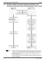
2.3
Striking a Balance between System Installation and
General Construction Work (Comprehensive Flow Chart)
Note:
10
Si39-303
1. The division of the work should be thoroughly clarified. (This applies particularly to work relating to the
connection of control wiring, fitting of remote controller and central control panel, boundary work on
areas such as connection of drain piping and humidification supply piping, inspection and foundation)
2. Keep a constant check on the progress of the construction work to avoid deviations from the air
conditioning work schedule.
3. For sleeve and insert work the positions of ceiling girders should be confirmed and sleeve and insert
requirement, hole diameters, positioning and numbers decided. This is particularly important in the case
of sleeves for drain piping.
General Information
Si39-303
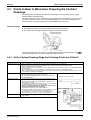
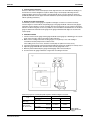
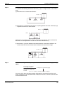
2.4
Points to Bear in Mind at the System Design
Points to Bear in Mind when Preparing the Contract
Drawings
The following points should be borne in mind when preparing the contract drawings from the original
drawings and the execution drawings.
The contract drawings for the air conditioning system are blueprints for the performance of the necessary
work which are drawn up on the basis of the original drawings in such a way that a working balance is
achieved between the specific requirements of each individual aspect of the work.
Contract Drawing
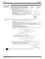
Objectives include:
! The drawings should be easily comprehensible to those carrying out the work.
! The contents of the drawings should not be subject to subsequent alteration.
The following is a list of the main points to be considered when preparing contract drawings for the
System and should be used as a reference during this stage of the work:
II
2.4.1 At the Contract Drawing Stage the Following Points are Critical!!
Check points
Arrangement of units
1.
2.
3.
4.
Refrigerant piping
1. Is the piping system correctly connected?
2. Are the rise and fall pipes correctly connected?
3. Are the lengths and height differences of the pipes within the
recommended limits?
Operational control
1. Are the interconnections between the piping and wiring of the
indoor and outdoor units clearly shown?
2. Are the numbers of the local setting switches clearly shown?
(Group No. and Unit No.)
3. Are the wiring connections between the remote controller and the
centralized and remote controls clearly shown?
Refer to the notes relating to the preparation of the control
wiring system diagrams (see next page)
4. Are the different types of wires clearly marked?
5. Are the any problems with the way the power supply cables and
control wiring have been separated or bound together?
6. Are the inter-floor connections of the control wiring correct?
7. Is the position of the remote controller clearly marked?
Miscellaneous
1. Have you checked the gradient of the drain piping? (Must be at
least 1/100)
General Information
Have you left the access passages clear and allowed sufficient room for servicing?
Have you taken full account of the possibility of short circuits? (Both indoor and outdoor units)
Can the air filters be replaced easily?
Have you indicated the size and location of the ceiling inspection ports? (Make sure there no other installations in
the area above)
5. Have you taken into account the depth of the installation area? (In case of ceiling built-in type)
6. Have you specified the position of the indoor unit clearly? (Have you taken full account of relevant features of the
local ventilation, humidity and lighting?)
11
Points to Bear in Mind at the System Design
Si39-303
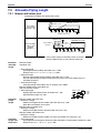
2.4.2 Main Considerations in Preparation of Control Circuit Diagrams
In addition to the design of the appropriate this system configuration it is also essential that the control
system be made amply clear. If the system is designed and installed without a clear, comprehensive plan
then problems are inevitably going to occur during the test run.
Servicing too will become much more time consuming than necessary. However, if control circuit diagrams
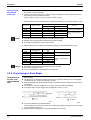
are prepared along with the contract drawings in order to make the total system clearly visible then the
essential points relating to the electrical connections will be easily understood, the test run will go off
without a hitch and the whole system will be rendered fully effective.
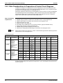
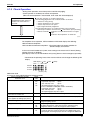
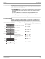
Step 1: Compiling
a System List
Note:
1.
2.
3.
4.
5.
6.
7.
8.
9.
Mark each outdoor unit with a code.
Add field settings and data for outdoor units, and outdoor unit No. if using sequential start.
Add the model number of each indoor unit connected to each refrigerant circuit.
Assign each indoor unit a code.
Fill in the location of each indoor unit.
Group indoor units controlled by one or two remote controllers. (group or individual control).
Assign central group Nos. if using centralized control.
Add field settings and optional equipment for indoor units.
Add unit No. if making separate field settings for each indoor unit under group control.
With the VRV II R410A Heat Pump Series, unit No. is determined through automatic addressing, therefore
readout unit Nos. after activating the power.
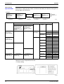
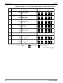
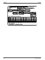
Example: System list
Outdoor Unit
Indoor Unit
Model Name
(code)
Field Settings
RXYQ16M
(PAC1)
Cool/Heat
selector:
Indoor unit
Low noise
operation
(L.N.O.P):
Individual control
Sequential start:
ON Defrost:
Earlier
Sequential start
No.
RXYQ18M
(PAC2)
Cool/Heat
selector:
Indoor unit
Low noise
operation
(L.N.O.P):
Individual control
Sequential start:
ON Defrost:
Earlier
Model Name System Name
Location
Remote
Controller
Group
Centralized
Control Group
No.
FXCQ32M
2F01
2nd floor
office
A
1–00
FXSQ63M
2F02
2nd floor
office
A
(1–00)
FXCQ40M
2F03
2nd floor
office
A
(1–00)
FXHQ63M
2F04
2nd floor
office
B
1–01
FXCQ50M
2F05
2nd floor
office
B
(1–01)
FXSQ32M
3F01
3rd floor
office
C
1–02
FXCQ40M
3F02
3rd floor
office
C
(1–02)
FXSQ40M
3F03
3nd floor
office
C
(1–02)
FXCQ50M
3F04
3rd floor
office
D
1–03
Unit No.
Optional
equipment, field
settings, etc.
For details on field settings and centralized control group No., refer to the installation manual and system
reference materials.
12
General Information
Si39-303
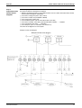
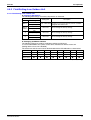
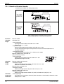
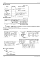
Step 2:
Preparation of the
Control Circuit
Diagrams
Points to Bear in Mind at the System Design
The following sequence should be followed in order to prepare control circuit diagrams in accordance with
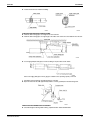
the system list which has already been completed:
Diagrams should be prepared for each individual outdoor unit. The outdoor unit model number should
be inserted into the diagram. (RXYQ16M)
Insert name of refrigerant system. (PAC1, PAC2)
Insert name of indoor unit. (FXCQ32M→CQ32M)
Insert system name of indoor unit.
Insert installation position. (Do this when demarcation is possible)
Insert remote controller control wiring. (Group) Indicated by solid line. ........Solid line.
Insert centralized control wiring. ........Dotted line
Insert Group No. (G No. for each indoor unit with U No. 0)
The control circuit diagrams are now complete.
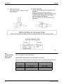
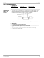
Example: Control circuit diagram
General Information
13
Installation
Si39-303
3. Installation
3.1
Step by Step Installation Procedure
The above list indicates the order in which the individual work operations are normally carried out but this
order may be varied where local conditions warrant such a change
14
General Information
Si39-303
3.2
Installation
Work Involved in Individual Operations and Points to be
Borne in Mind
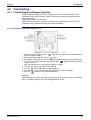
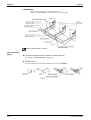
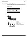
3.2.1 Sleeve and Insert Work
! Operational steps
Preliminary talks
with
construction
company
Determine
position, size and
number of units
required
Carry out work
Check work
(V0957)
Positioning of the
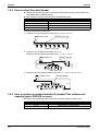
Pipe Holes
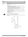
a) The through holes for the drain piping should be positioned such that the pipes have a downward
gradient. (The gradient must be at least 1/100. The thickness of the insulating materials must also be
taken into consideration.)
b) The diameter of the through holes for the refrigerant piping should include an allowance for the
thickness of the heat insulation materials. (It is a good idea to think of the liquid and gas pipes as pairs.)
c) Attention should be paid to the construction of the beam themselves since there are sometimes parts of
the beam which cannot be used to accommodate through holes.
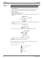
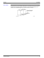
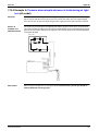
Example: Through holes in a reinforced concrete beam
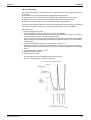
Positioning the
Insert
a) An insert is a metal tool which is inserted into a floor or a beam before the concrete is set such that
fittings such as ducts, pipes or suspension bolts for hanging units can be fitted into place later. The
positions of the inserts must be decided early.
Example: Steel insert
Important point:
1. The weight of the fitting to be suspended must be taken into account when choosing the insert.
General Information
15
Installation
Si39-303
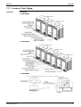
3.2.2 Installation of Indoor Unit
! Operational steps
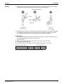
Determine
installation
position
Mark installation
position
Fit suspension
bolts
Fit indoor unit
(V0960)
Positioning
3 essential points when installing an indoor unit
1. Height: Take care to account for final ceiling facing surface level
2. Level: Level fitting is essential. (within ±1 degree of horizontal)
3. Direction: The unit must be fitted in line with the ultimately visible ceiling joints
Important points
1. The suspension bolts must be strong enough to support the weight of the indoor unit.
2. Optional features must be added to the indoor unit prior to installation.
3. The model name should be checked prior to installation.
4. Take care to align the main unit correctly. (Bearing in mind piping layout and direction of blow out)
5. Leave sufficient space for servicing to be carried out.
6. Make inspection holes for model which need them.
7. Fit the unit to ensure proper drainage.
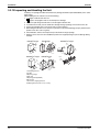
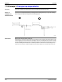
Example: Ceiling mounted cassette type (FXCQ63M)
16
General Information
Si39-303
Installation
3.2.3 Refrigerant Pipe Work
! Operational steps
Install indoor unit
Fit pipes
provisionally
Cut pipes to size
Solder
Flushing
Replace nitrogen
Air tight test
Vacuum drying
(V0963)
The “3 principles of refrigerant piping” must be strictly observed
Cause of problem
Actoin to avoid problem
l Rainwater, work water,
Dry
The 3 Principles
of Refrigerant
Piping
etc. gets into pipes from
outside
l Moisture generated inside
pipes due to condensation
Pipe covering
Flushing
Vacuum drying
l Formation of oxides inside
Clean
pipes during soldering
l Dirt, dust or other
extraneous material gets
into pipes from outside
l Leak from soldered area
Replace nitrogen
Flushing
Pipe covering
Use the proper materials (copper pipe,
solder, etc.)
Air tight
Adhere strictly to standard soldering
work practice
l Leak from flared area
l Leak from flange area
Air tight test
Adhere strictly to standard flaring work
practice
Adhere strictly to standard flange
connection work parctice
(V0964)
The 3 principles of refrigerant piping
Dry
Make sure there is no moisture
inside the pipes
General Information
Clean
Air tight
Make sure there is no dirt inside the Make sure the refrigerant does not
pipe
leak out
17
Installation
Method for
Replacing
Nitrogen
(Brazing)
Si39-303
If brazing work is carried out without passing nitrogen gas through the pipes which are being brazed then
this allows the formation of oxidation bubbles on the inside surface of the pipes. These oxidation bubbles
are then carried along inside the pipes to cause damage to various members of the system such as valves
or compressors and the system ceases to function properly.
In order to avoid this problem nitrogen is passed through the pipes while the soldering work is being
carried out. This operation is known as nitrogen replacement. (Air is replaced by nitrogen)
This is standard work practice for all brazing work.
Important points:
1. The gas used must be nitrogen (oxygen, carbon dioxide and flon should not be used.)
2. A pressure regulator must be used.
18
General Information
Si39-303
Covering of
Refrigerant Pipes
Installation
Covering is an extremely important operation as it prevents water, dirt or dust from getting inside
the pipes. Moisture inside the pipes was a constant source of trouble in the past. The utmost care is
required to nip this problem in the bud.
The end of each pieces of pipe must be covered. “Pinching” is the most effective method but “taping” is
an simple alternative which may be used according to the work area and term of work.
Location
Term of Work
Covering Method
Outdoors
1 months or more
Pinching
Less than 1 months
Pinching or taping
Irrelevant
Pinching or taping
Indoors
1. Pinching method
The end of the copper pipe is squeezed together and the gap brazed.
2. Taping method
The end of the copper pipe is covered with PVC tape (vinyl tape).
<Taping method>
Particular care should be taken during the following operations:
! When passing copper pipe through a penetration hole (Dirt easily gets into the pipe).
! When copper pipe is located outside (Rainwater gets in)
(Special care is needed when the pipes are standing vertically outside)
General Information
19
Installation
Refrigerant Pipe
Flushing
Si39-303
Flushing is a method of cleaning extraneous matter out of pipes using pressurized gas.
[3 major effects]
1. Removal of oxidation bubbles formed inside copper pipes when “nitrogen replacement is insufficient”
during soldering work
2. Removal of extraneous material and moisture from pipes when covering has been insufficient
3. Checks connections in pipes linking outdoor and indoor units (Both liquid and gas pipes)
[Example of procedure]
1. Set pressure regulator on nitrogen cylinder.
∗The gas used must be nitrogen.
(There is a danger of condensation if fleon or carbon dioxide are used and oxygen carries the risk of
explosions.)
2. Connect the charge hose from the pressure regulator to the service port on the liquid pipe side of the
outdoor unit.
3. Fit blanking plugs to all indoor units (B) other than unit A.
4. Open the main valve on the nitrogen cylinder and set the pressure regulator to 0.5MPa.
5. Check that the nitrogen is passing through the unit A liquid pipe.
6. Flushing.
! Block the end of the pipe with the insulation of your hand.
↓
! When the gas pressure becomes too great to contain remove insulation quickly. (First flush)
↓
! Block the end of the pipe with insulation again.
↓
(Carry out second flushing)
20
General Information
Si39-303
Installation
(The nature and amount of the extraneous material inside the pipe can be checked during flushing by
placing a rag lightly over the end of the pipe. In the unlikely case that even a small quantity of moisture is
found then the inside of the pipe should be dried out thoroughly.)
Action:
1. Flush the inside of the pipe with nitrogen gas. (Until such time as the moisture disappears.)
2. Carry out a thorough vacuum drying operation. (See page 31)
Close the main valve on the nitrogen cylinder.
Repeat the above operation for unit B.
When the liquid pipe operations have been completed then do the same with the gas pipes.
Choice of
Materials for
Refrigerant
Piping
a) Refrigerant piping
! The piping used must meet the requirements of the JIS standard or equivalent. (Size, material,
thickness, etc.)
Specification: Oxidized phosphorous seamless copper pipe
! Long pipe lengths or coiled pipe (copper pipe with heat insulation coating) should be used to avoid the
necessity for frequent brazing.
(* Make sure the thickness and material shall be selected in accordance with following table.)
! Size of Refrigerant Piping
Outside Diameter (mm)
Material
φ6.4
0
φ9.5
0
φ12.7
0
φ15.9
0
φ19.1
1/2H
φ22.2
1/2H
φ25.4
1/2H
φ28.6
1/2H
φ31.8
1/2H
φ34.9
1/2H
φ38.1
1/2H
φ41.3
1/2H
*The thickness and material shall be selected in accordance with local code.
b) Brazed joints and special branches
1. General use (L bend joint, socket joint, T joint, etc.)
! Joints must meet the requirements of the relevant JIS standard. (Size, materials, thickness, etc.)
2. Special branches
! The Daikin outdoor unit multi connection kit, REFNET joint, REFNET header or Reducing socket should
be used.
Example: R410A RXYQ-M Series
Refer detail of DAIKIN REFNET joint and REFNET header on page 126.
General Information
21
Installation
Si39-303
c) Brazing
The Multi-System requires only copper/copper jointing and the jointing method is explained below.
! The use of “hard solder” is essential.
The R410A Heat Pump RXYQ-M Series uses a wide range of piping sizes. You should therefore be careful
when selecting the nozzle tip. If a small nozzle tip is used for brazing piping of large diameters such as
φ38.1 and φ44.5, brazing flow becomes poor.
Table 1: Correlation of nozzle tip and size of refrigeration piping
Brazing filler diameter φ
Nozzle tip No.
# 200
# 225
# 250
# 315
# 400
# 450
# 500
1.6
2.4
3.2
6.4
9.5
Piping size
12.7
15.9
19.1
22.2
25.4
28.6
31.8
34.9
38.1
41.3
(V0977)
Note:
22
The values in the table above are for type B torch (French).
General Information
Si39-303
Brazing
Installation
a) Brazing work should be carried out such that the final result is directed either downwards or sideways.
An upward direction should be avoided wherever possible. (to prevent leakage)
b) Liquid and gas pipe branches should always be dealt with in the specified way with attention being paid
to the direction of the fitting and its angle. (to prevent oil return or drift) For example see page 148.
c) It is standard working practice to use the nitrogen replacement method when brazing.
Important points
1. Every effort must be made to avoid fire. (Clean area where brazing is to be performed and make sure
that fire fighting equipment and water are ready to hand.)
2. Be careful of burns.
3. Make sure that the gap between the pipe and the joint is correct. (To prevent leaks)
4. Is the pipe adequately supported?
! As a rule the gaps between supports for horizontal piping (copper pipe) are as follows:
Copper pipe support spacing
Nominal diameter
Maximum gap (m)
(From HASS 107-1977)
20 or less
25~40
50
1.0
1.5
2.0
! The copper pipe should not be secured directly by metal brackets.
General Information
23
Installation
Flare Connection
Si39-303
(a) Stiffened pipe must always be annealed at least once prior to the flaring work.
(b) A pipe cutter must be used to cut the pipe. (A large pipe cutter must be used where the pipe has a large
diameter. When cutting a pipe which is too big for the pipe cutter a metal saw may be used but care
must be taken to ensure that the debris from sawing does not get into the pipe.)
(c) Set the flaring tool to make sure the flare size remains within the prescribed limits.
Nominal diameter
External diameter of pipe d
1/4
6.35
Pipe widening dimensions A
9.1
3/8
9.52
13.2
1/2
12.7
16.6
5/8
15.88
19.7
3/4
19.05
24.0
New Rank Compatible Flare Tool
Compared to previous refrigerants, the components of a HFC refrigerant is small. R410A also has a higher
pressure than other refrigerants. Therefore, in order to strengthen the intensity of the form and size of the
flare section used for R410A (class 2) apparatus, unlike the specification of the conventional refrigerants, it
was set up with different standards.
When carrying out flare processing, use a new rank compatible flare tool or a conventional flare tool.
Flare Gauge (Adapter Corresponding to the New Rank)
When using the later, use a flare gauge to take out the pipe from the gauge bar, adjust it, and then carry out
the flare processing.
Size
Thickness
12mm×72mm
1.0×0.5mm Each
Flare gauge
Size from the dice surface to the copper tip (in mm)
Name
Outer
diameter
Wall
thickness
1/4
3/8
1/2
5/8
6.35
9.52
12.70
15.88
0.8
0.8
0.8
1.0
Previous refrigerant (R22, R407C etc.)
The conventional flare tool
Clutch type
0~0.5
0~0.5
0~0.5
0~0.5
R410A
The conventional flare tool
Clutch type
1.0~1.5
1.0~1.5
1.0~1.5
1.0~1.5
(d) Coat the inner and outer surface of the flare with refrigerator oil (Ester or ether oil). (this ensures that the
flare nut passes smoothly, preventing the pipe from twisting.)
Do not use SUNISO-4GS oil.
Important points
1. Burrs should be carefully removed.
2. 2 spanners should be used to grip the flare nuts.
3. The flare nut must be inserted before starting the flaring operation.
4. The appropriate amount of torque should be used to tighten the flare nut.
Standard torques for tightening flare nut
Size
1/4(6.4φ)
3/8(9.5φ)
1/2(12.7φ)
5/8(15.9φ)
3/4(19.1φ)
±10%
Torque
(kgf-cm)
144~176
333~407
504~616
630~770
990~1210
(N-cm)
1420~1720
3270~3990
4950~6030
6180~7540
9270~11860
5. Check that there is no superficial damage to the surface of the flare.
24
General Information
Si39-303
Installation
Flaring Procedure
General Information
25
Installation
Not
recommendable
but in case of
emergency
Si39-303
You must use a torque wrench but if you are obliged to install the unit without a torque wrench, you may
follow the installation method mentioned below.
After the work is finished, make sure to check that is no gas leak.
When you keep on tightening the flare nut with a spanner, there is a point where the tightening torque
suddenly increases. From that position, further tighten the flare nut the angle shown below:
26
Pipe size
Further tightening angle
Recommended arm length of tool
6.4 (1/4”)
60 to 90 degrees
Approx. 150mm
9.5 (3/8”)
60 to 90 degrees
Approx. 200mm
12.7 (1/2”)
30 to 60 degrees
Approx. 250mm
15.9 (5/8”)
30 to 60 degrees
Approx. 300mm
19.1 (3/4”)
20 to 35 degrees
Approx. 450mm
General Information
Si39-303
Flange
Connection
Installation
a) The flange sheet surface should be clean and undamaged. (Clean any dirt away with a cloth and check
that there has been no damage.)
b) Coat the flange sheet surface with refrigeration oil (Ester or ether oil) and then insert the packing. (Do
not use SUNISO oil.)
c) Tighten the bolts in opposite corners first to ensure that the connection is true.
[Example]
Order:A→C→B→D
The bolts should be tightened little by
little in the above order such that the
same degree of torque is applied
evenly to each corner.
Important points
1. Only clean refrigeration/oil should be used to coat the flange. (i.e. free from dirt or water)
2. The correct amount of torque should be applied when tightening the flange bolts.
Standard torques for tightening screws and bolts
ISO hexagonal bolt
Class
Size
General Information
5.8(5T)
10.9(10T)
kgf-cm ±15%
N-m ±15%
kgf-cm ±15%
M8
125
1230
302
N-m ±15%
2960
M10
257
2520
620
6080
M12
436
4280
1,050
10,300
M16
1,030
10,100
2,480
24,300
M20
2,050
20,100
4,950
48,500
27
Installation
Si39-303
3.2.4 Thermal Insulation Work (Refrigerant Piping)
! Operational steps
Refrigerant pipe
work
Insulation (with
the exception of
the jointed
areas)
Air tight test
Insulation
(jointed areas)
(V0985)
Materials
The thermal insulation materials which are used must be well able to withstand the heat from the pipes.
Example:
Heat pump type: Heat resistant polyethylene foam (heat resistance of at least 120°C)
Cooling only: Polyethylene foam (heat resistance of 100°C or more)
Essential Points
of Thermal
Insulation
The insulation of jointed areas such as the soldered, flared or flanged sections should only be carried out
after the successful completion of the air tight test.
Attention should be paid to the unit model and its operating conditions since there are occasions when the
gas and liquid pipes also need to be thermally insulated.
! Important points
1. The thickness of the thermal insulation material must be determined in the light of the pipe sizes.
Pipe size
Thickness of insulation material
6.4mm~25.4mm
10mm or more
28.6mm~38.1mm
15mm or more
2. It will be necessary to increase the values in the above table for top floors or where conditions are hot
and humid.
3. Where a customer supplies his own specifications then these must be adhered to.
4. Where it is anticipated that the air conditioning unit will be operated at external air temperatures of 10°C
or less then thermal insulation will also be required for the liquid pipes.
28
General Information
Si39-303
Installation
3.2.5 Air Tight Test
! Operational steps
Complete
refrigerant pipe
installation work
Pressurize
Check for pressure drop
Success
Locate and repair leaks
(V0987)
Essential Points
of Testing
(Maintaining
Pressure Over a
Period)
The key to successful testing is strict adherence to the following procedure:
a) The liquid and gas piping in each refrigerant system should be pressurized in turn in accordance with
the following steps. (Nitrogen gas must be used.)
! Step 1: increase pressure to 0.3MPa for 3
minutes or more
Indicates existence of major leaks
! Step 2: increase pressure to 1.5MPa for 3
minutes or more
! Step 3: increase pressure to 3.80MPa for
approx. 24 hours
Indicates existence of minor leaks
∗Increasing the system pressure to 3.80MPa does not guarantee the identification of minor leaks if
pressure is maintained for only a short time. It is therefore recommended that the system remain
pressurized in accordance with Step 3 above for at least 24 hours.
Note:
The pressure must on no account be increased beyond 3.80MPa.
b) Check for pressure drop
If there is no drop in pressure then the test is deemed a success.
If the pressure drops then the leak must be located. See following page.
However, if there is a change in the ambient temperature between the pressurizing stage and the time
when you check for a drop in pressure then you will have to adjust your calculations accordingly since a
change of 1°C can account for a pressure change of approximately 0.01MPa.
Compensating adjustment value:
(temperature at time of pressurizing – temperature at time of checking) × 0.01
Example:
Time of pressurizing: 3.80MPa 25°C
24 hours later: 3.75MPa 20°C
The pressure drop in such a case is deemed to be zero (successful test).
General Information
29
Installation
Checking for
Leaks
Si39-303
[Check 1] (Where pressure falls while carrying out Steps 1 to 3 described on previous page)
! Check by ear......Listen for the sound of a major leak.
! Check by hand......Check for leak by feeling around jointed sections with hand.
! Soap and water check (∗Snoop)......Bubbles will reveal the presence of a leak.
[Check 2] (When searching for a minor leak or when there has been a fall in pressure while the system has
been fully pressurized but the source of the leak cannot be traced.)
1. Release the nitrogen until the pressure reaches 0.3MPa.
2. Increase pressure to 1.5MPa using gaseous flon gas (R410A). (Nitrogen and flon gas mixed)
3. Search for the source of the leak using a leak detector.
4. If the source of the leak still cannot be traced then repressurize with nitrogen up to 3.80MPa and check
again. (The pressure must not be increased to more than 3.80MPa.)
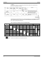
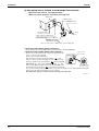
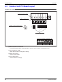
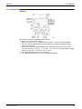
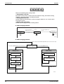
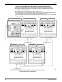
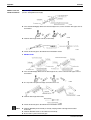
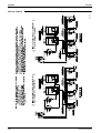
Setup of Air-light Test
As for the air-tight test, the setup of devices shown in the following figure is recommended with
considerations given to “vacuum drying and refrigerant additional charging”, which are operation
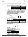
steps following the air-tightness test.
In order to conduct the air-tight test, with stop valves of 8.Gas side, 10.liquid side and 15.Oil
equalization piping and those of the refrigerant and vacuum pump all closed, then open the
nitrogen gas stop valve, 7.Valve A, and 16.Valve B while adjusting the nitrogen gas pressure
regulating valve, thus increasing the pressure.
One outdoor unit installed: In case of RXYQ5-16MY1B
9
17
1
10
8
4
11
7
3
2
12
5
6
13
When multiple outdoor units installed:
In case of RXYQ18-48MY1B
9
17
1
4
8
10
13
15
7
3
9
1.Pressure reducing valve
2.Nitrogen
3.Refrigerant cylinder
4.Siphon system
5.Measuring instrument
6.Vacuum pump
7.Valve A
8.Gas side
9.Outdoor unit
10.Liquid side
11.Indoor unit
12.Shutoff valve service port
13.Charge hose
14.To indoor unit
15.Oil-equalizing line
16.Valve B
17.Dotted lines represent onsite piping
2
16
5
14
12
6
! Important points
1. Where the lengths of piping involved are particularly long then the air tight test should be carried out
block by block.
Example:
1. Indoor side
2. Indoor side + vertical pipes
3. Indoor side + vertical pipes + outdoor side
30
General Information
Si39-303
Installation
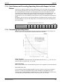
3.2.6 Vacuum Drying
What is vacuum
drying?
Vacuum drying is:
“The use of a vacuum pump to vaporize (gasify) the moisture (liquid) inside the pipes and expel it leaving
the pipes completely dry inside.”
At 1 atm (760 mmHg) the boiling point (evaporating temperature) of water is 100°C but if a vacuum is
created inside the pipes using a vacuum pump then the boiling point is rapidly reduced as the degree of the
vacuum is increased. If the boiling point is reduced to a level below that of the ambient temperature then
the moisture in the pipes will evaporate.
<Example>
When outside temperature is 72°C
As shown in the table on the right, the degree
of vacuum must be lowered below –75.2mmHg.
→
Pressure
Boiling point
of water (°C)
∗mmHg
Pa
Torr
40
–705
7333
55
30
–724
4800
36
26.7
–735
3333
25
24.4
–738
3066
22
22.2
–740
2666
20
20.6
–742
2400
18
17.8
–745
2000
15
15.0
–747
1733
13
11.7
–750
1333
10
7.2
–752
1066
8
0
–755
667
5
Above figures (mmHg) are gauge pressure readings.
The evacuation of air conditioner piping provides the following effects.
1. Vacuum drying
2. Removes air and nitrogen (used in air-tightness test) from the inside of pipes.
Therefore, it is necessary to ensure that the both purposes have been achieved in the vacuum drying
operation.
Key points
Lower the degree of vacuum to below –755mmHg
(V1216)
General Information
31
Installation
Si39-303
Choosing a
Vacuum Pump
General
Refrigerant piping content volume of the VRVII R410A Series is larger than the VRV Inverter Series, and
consequently takes more time for vacuum drying. If you have time to spare, you may use the same vacuum
pump, but if you want to save time, you will have to use a pump with higher exhaust velocity (exhaust
volume).
The Necessity for Counter Flow Prevention
After the vacuum process of the refrigerant cycle, the inside of the hose will be vacuumed after stopping the
vacuum pump, and the vacuum pump oil may flow back. Moreover, if the vacuum pump stops during the
operation by some reason, the same thing happens.
In such cases, different oil mixes in the HFC system refrigerant apparatus cycle, and becomes the cause of
a refrigerant circuit trouble. Therefore, in order to prevent the counter flow from the vacuum pump, a check
valve is needed.
Vacuum pump with check valve or vacuum pump adapter
Vacuum pump adapter
Reverse flow preventive
vacuum adapter
Vacuum pump with
check valve
1. Vacuum pump performance
The 2 most import things for determining vacuum pump performance are as follows:
(1) Exhaust velocity
(2) Degree of vacuum
(1) Exhaust velocity
Exhaust volume is usually expressed as l/min or m³/h. The larger the number, the faster vacuum id
achieved.
Generally speaking, the faster the exhaust velocity, the larger and heavier the vacuum pump itself is.
Commercially available vacuum pumps (exhaust velocity of 20 - 30 l/min) usually take an extremely
long time to achieve vacuum. (We recommend a vacuum pump of approx. 60 - 100 l/min.)
(2) Degree of vacuum
Ultimate vacuum varies largely according to use of the vacuum pump. Vacuum pumps used for vacuum
forming cannot be used for vacuum drying. (A vacuum pump with a high degree of vacuum is required.)
When selecting a vacuum, you should select one which is capable of achieving 0.2 Torr of ultimate
vacuum.
Degree of vacuum is expressed in Torr, micron, nnHg, and Pascal (Pa). The units correlate as follows:
Unit
Standard atmospheric pressure
Perfect vacuum
kg/cm2
0
–1.033
kg/cm2 abs
1.033
0
Torr
760
0
Micron
Micron
760000
0
∗mmHg
mmHg
0
760
hPa
1013.33
0
Gauge Pressure
Absolute Pressure
Torr
Pa
Degree of vacuum must be within the range expressed by
0 Torr
5 Torr
760 Torr
0 Pa
667 Pa
1013.33 hPa
760 mmHg
755 mmHg
0 mmHg
Perfect vacuum
Vacuum target value
Standard atmospheric pressure
(V0992)
32
General Information
Si39-303
Installation
2. Vacuum pump maintenance
Because of their nature, most vacuum pumps contain large amounts of oil which lubricates bearings, etc.,
and functions to enhance airtightness of pistons. When using a vacuum pump to discharge air from
refrigerant piping, moisture in the air tends to get mixed in with the oil. You must therefore change oil
periodically and make sure the proper oil level is maintained. (Perform periodic inspections in accordance
with the operating instructions.)
3. Degree of vacuum measurement
An extremely accurate vacuum gauge is required to test degree of vacuum. You cannot accurately
measure degree of vacuum with the compound gauge on the gauge manifold. A Pirani vacuum gauge is
required to measure degree of vacuum accurately. Because Pirani gauges are very sensitive and require
extreme care when using, they are not very suitable for use in the field. You should therefore use the Pirani
gauge to calibrate the attached vacuum gauge on the gauge manifold and the degree of vacuum of the
vacuum pump.
4. Calibration method
1. Connect a Pirani vacuum gauge and the gauge manifold vacuum gauge (0 - 760 mmHg) to the vacuum
pump at the same time, and run the pump for about 3 minutes.
2. Make sure the reading of the Pirani vacuum gauge is 5 Torr (667 Pa) or less. The reading of
conventional vacuum pumps lowers to about 0.2 Torr.
If the reading is not 5 Torr or less, check the vacuum pump oil. (Oil is low in many cases.)
3. Check the attached gauge on the gauge manifold. Adjust the gauge if the reading is not exactly correct.
4. Adjust the gauge manifold valve so that the Pirani vacuum gauge reads 5 Torr.
5. Mark the position indicated by the gauge manifold gauge with an oil based ink pen.
6. Use the mark of the gauge manifold as a target when vacuuming in the field.
(Reference) Types of vacuum pump with respective maximum degree of vacuum
Type
Oil Rotary
(Oil Using)
Maximum Degree of Vacuum
0.02 mmHg
Suitable
Suitable
50 l/min
Unsuitable
Suitable
Suitable
Suitable
0.02 mmHg
40 l/min
General Information
Air Expulsion
100 l/min
10 mmHg
Oilless Rotary
(No Need of Oil)
Use
Expulsion Capacity Vacuum Drying
←Many handy
pumps fall into this
category
33
Installation
Si39-303
Vacuum Drying
Procedure
There are two vacuum drying methods and the appropriate one should always be chosen to conform with
individual local conditions.
[Normal vacuum drying]........The standard method
[Operational steps]
1. Vacuum drying (1st time): Connect a manifold gauge to the service port of the liquid or gas pipe and
operate the vacuum pump for at least 2 hours.
(The degree of vacuum produced should be in excess of 5 mmHg)
If after 2 hours the vacuum produced has not exceeded 5 mmHg then either there is moisture in the
pipe or there is a leak. Operate the vacuum pump for a further hour.
If, even after 3 hours, the vacuum has not reached 5 mmHg then check the system for a leak.
2. Carry out maintained vacuum test.
Produce a vacuum in excess of –755 mmHg and do not release it for an hour or more. Check the
vacuum gauge to make sure that it has not risen. (If the gauge does rise then there is still moisture in
the pipe or there is a leak somewhere.)
3. Additional charge of refrigerant.
Connect the charging cylinder to the liquid pipe service port and charge with the required amount of
refrigerant.
4. Open stop valve to the full.
Open the stop valves on the liquid and the gas pipes to the full.
Note:
34
Vacuums should be produced in both the liquid and the gas pipes.
(Because there are a large number of functional components in the indoor unit which cut off the vacuum
mid–way through)
General Information
Si39-303
Installation
Special vacuum drying
This vacuum drying method is selected when there is a suspicion that there may be moisture in the pipes.
For example:
! When moisture was discovered during the refrigerant pipe flushing operation
! When there is a risk of condensation forming inside the pipes during periods of heavy rainfall
! When there is a risk of condensation forming inside the pipes due to a long term of works
! When there is a risk that rainwater may have entered the pipes during installation
The special vacuum drying method is the same as the standard method except that nitrogen is introduced
into the pipes to break the vacuum on one or more occasions during the course of the operation.
[Operational steps]
1. Vacuum drying (1st time): 2 hours
2. Vacuum breaking (1st time): Use nitrogen to raise pressure to +0.05MPa.
(Since the nitrogen gas used to break the vacuum is dry nitrogen this process serves only to enhance
the overall drying effect of the vacuum drying operation itself.
However, since the effectiveness of this process is severely impaired by a high moisture level inside the
pipes, the utmost care is required during installation to see that water does not enter or form inside the
refrigerant pipes.)
3. Vacuum drying (2nd time): Operate the vacuum pump for at least 1 hour.
(Observations: Degree of vacuum has reached 5 mmHg. If the degree of vacuum has not reached 5
mmHg after 2 hours or more then repeat the operations at 2 (vacuum breaking) and 3 (vacuum drying)
above.)
4. Carry out maintained vacuum test: 1 hour
5. Additional charge of refrigerant
6. Open stop valve to the full
∗
General Information
The gas used for the vacuum breaking operation must be nitrogen.
(The use of oxygen brings a serious risk of explosions)
35
Installation
Si39-303
3.2.7 Additional Charge of Refrigerant at installation time
! Operational steps
Use the length of the piping to
calculate the amount of
refrigerant required
Additional charge of
refrigerant
(V0995)
Important points
1. The results of all calculations must be recorded. (Make a list.)
2. The refrigerant will need to be additionally charged whenever the distance between the outdoor unit and
the most distant indoor unit is more than 10m.
3. The additional charging operation should be carried out by input of liquid from Service port at liquid stop
valve following completion of the vacuum drying operation.
4. When the additional charging operation cannot be satisfactorily completed use the action of the
compressor to complete the additional charging during the test run.
Refrigerant
Charging
Instructions
HFC401A are Quasi-azeotropic* refrigerants. Therefore, these refrigerants must be charged in the liquid
state. When charging the refrigerant into equipment from the refrigerant cylinder, turn the refrigerant
cylinder upside down.
Important: Make sure that the refrigerant (liquid) is taken out from the bottom part of the refrigerant cylinder.
Do not take out the refrigerant (gas) at the upper part of the refrigerant cylinder for charging.
Caution
Since some refrigerant cylinders differ in the internal mechanism, it is necessary to examine the cylinder
carefully. (Some cylinders have a siphon tube to eliminate the need for turning it upside down.)
Siphon tube
36
General Information
Si39-303
Installation
<*Non-azeotropic refrigerants or Quasi-azeotropic refrigerants>
When a refrigerant is a mixture of two or more types with different evaporation temperature, it is called a
non-azeotropic refrigerant. If all refrigerant components evaporate at the same temperature, the mixture is
called an azeotropic refrigerant.
If a non-azeotropic refrigerant is charged into equipment in the gaseous state, the refrigerant components
that evaporate sooner than others enter the equipment, and the refrigerant that evaporate after others
remain in the refrigerant cylinder.
*Quasi-azeotropic mixture refrigerant: mixture of two or more refrigerants having similar boiling points.
Caution items
The following devices designed for R-22 cannot be used to charge the new refrigerants. Be sure to use the
devices specifically designed for the new refrigerants.
1. Charging cylinder...(Pressure resisting specification is different.)
2. Gauge manifold (including hose)...(same as above)
General Information
37
Installation
Si39-303
3.2.8 Drain Pipe Work (Indoor)
! Operational steps
Install indoor unit
Check for water
Connect drain pipe
Insulate drain pipe
leaks
(V0999)
Drain Pipe
Gradient and
Support
a) The drain pipe must be fitted at a gradient of at least 1/100.
The drain pipe should be as short as possible and free from airlocks.
b) Suspension bolts should be used to support long stretches of drain pipe in order to ensure that a
gradient of 1/100 is maintained. (PVC pipes should not be bent)
Spacing of supports for horizontal piping
Class
Nominal diameter
Spacing
Rigid PVC pipe
25~40mm
1~1.5m
c) The length of pipe laid horizontally should be kept to a minimum.
Drain Trap
Fit any indoor unit whose drain pipe connection is subjected to negative pressure, with a drain trap.
(FXYMP40~125 only)
a) Rig the drain trap as shown in the drawing bellow.
b) Provide one trap per unit. A single trap for converging units will prove ineffective.
c) Rig the trap to allow for future cleaning.
38
General Information
Si39-303
Grouped Drain
Piping
Installation
1. It is standard work practice to make connections to the main pipe from above. The pipe down from the
combination should be as large as possible.
2. The pipework should be kept as short as possible and the number of indoor units per group kept to a
minimum.
Use of an
Auxiliary Drain
Hose (Flexible)
If a drain pan made of polystyrene foam is used then an auxiliary drain hose (flexible) is also essential. A
flexible drain hose permits the drain socket and drain pipe to be connected without difficulty and prevents
any undue strain being placed on the drain pan.
Important points
1. The drain pipe should be at least equal in size to that of the indoor unit.
2. The drain pipe is thermally insulated to prevent the formation of condensation inside the pipe.
3. The drain up mechanism should be fitted before the indoor unit is installed and when the electricity has
been connected some water should be added to the drain pan and the drain pump checked to see that
it is functioning correctly.
4. All connections should be secure. (Special care is needed with PVC pipe)
The use of a colored adhesive with PVC pipes will help you to remember to connect them up.)
General Information
39
Installation
Si39-303
Piping Diameter
for Grouped
Drain Pipes
! Select piping diameter from the below table in accordance with the amount of condensation drained by
all units with a common drain pipe.
! Consider 2 l/hr of drainage for every 1 HP. For example, drainage from 3 units running at 2 HP and 2
units running at 3 HP is calculated as follows.
2 (l/hr) × 2 (HP) × 3 (units) + { 2 (l/hr) × 3 (HP) × 2 (units) = 24 l/hr
1. Relationship between horizontal pipe diameter and allowable drainage (for extended ventilation system)
Notes:
Allowable flow rate (l/hr)
JIS nominal
Vinyl chloride pipe
diameter (mm)
Piping gradient 1:50
Piping gradient 1:100
VP20
20
39
27
VP25
25
70
50
VP30
31
125
88
VP40
40
247
175
VP50
51
473
334
Remarks
(Reference value) Cannot
be used in grouped piping.
Can be used in grouped
piping.
! Calculations have been made with water area inside the pipe as 10%.
! Allowable flow rate figures below the decimal have been discarded.
! Use VP30 or larger pipe after the convergence point.
2. Relationship between riser diameter and allowable drainage (for extended ventilation system)
Notes:
JIS nominal
Vinyl chloride pipe
diameter (mm)
Allowable flow rate
(l/hr)
VP20
20
220
VP25
25
410
VP30
31
730
VP40
40
1440
VP50
51
2760
VP65
67
5710
VP75
77
8280
Remarks
(Reference value) Cannot
be used in grouped piping.
Can be used in grouped
piping.
! Allowed flow rate figures below the decimal have been discarded.
! Use VP30 or larger pipe in risers.
! Use the same drain pipe for the humidifier as the indoor unit.
3.2.9 Drain Piping for Each Model
Ceiling Mounted
Cassette Type
(FXCQ-M Double
flow)
1. Rig drain piping
! The diameter of the drain pipe should be greater than or equal to the diameter of the connecting pipe
(vinyl tube, pipe size: 25 mm; outer dimension: 32 mm).
! Keep the drain pipe short and sloping downwards at a gradient of at least 1/100 to prevent air pockets
from forming.
! If the drain hose cannot be sufficiently set on a slope, execute the drain raising piping.
! To keep the drain hose from sagging, space hanging wires every 1 to 1.5 m.
! Use the attached drain hose and clamp metal.
Insert the drain hose into the drain socket, up to the white tape. Tighten the clamp until the screw head
is less than 4mm from the hose.
! Wrap the attached sealing pad over the clamp and drain hose to insulate.
40
General Information
Si39-303
Installation
! Insulate the drain hose inside the building.
(PRECAUTIONS FOR DRAIN RAISING PIPING)
! Install the drain raising pipes at a height of less than 310 mm.
! Install the drain raising pipes at a right angle to the indoor unit and no more than 300 mm from the unit.
! If converging multiple drain pipes, install according to the procedure shown below.
Select converging drain pipes whose gauge is suitable for the operating capacity of the unit.
2. After piping work is finished, check drainage flows smoothly.
! Open the water inlet lid, add approximately 2500 cc of water gradually and check drainage flow.
WHEN ELECTRIC WIRING WORK IS FINISHED
! Check drainage flow during COOL running, explained under "TEST OPERATION".
General Information
41
Installation
Si39-303
WHEN ELECTRIC WIRING WORK IS NOT FINISHED
! Remove the electric parts box lid, connect a power supply and remote controller to the terminals. (Refer
to the How to CONNECT WIRINGS (Refer to Installation Manual))
Next, press the inspection/test operation button “
” on the remote controller. The unit will engage
the test operation mode. Press the operation mode selector button “
” until selecting FAN
OPERATION “
”. Then, press the ON/OFF button “
”. The indoor unit fan and drain pump will
start up. Check that the water has drained from the unit. Press “
” to go back to the first mode.
! You can check whether drainage is satisfactory or not by removing the access opening lid and checking
the water level of the drain pan through the access opening.
! Be careful when doing so because the fan is turning at the same time.
42
General Information
Si39-303
Installation
Ceiling Mounted
Cassette Type
(FXFQ-M Multiflow)
1. Rig drain piping
n Lay pipes so as to ensure that drainage can occur with no problems.
n Employ a pipe with either the same diameter or with the diameter larger (excluding the raising section) than
that of the connecting pipe (PVC pipe, nominal diameter 25 mm, outside diameter 32 mm).
n Keep the drain pipe short and sloping downwards at a gradient of at least 1/100 to prevent air pockets from
forming.
n If the drain hose cannot be sufficiently set on a slope, execute the drain raising piping.
n To keep the drain hose from sagging, space hanging wires every 1 to 1.5 m.
Hanger bracket
1/100 gradient or more
1–1.5 m
WRONG
GOOD
Fig. 19
Fig. 18
n Use the attached drain hose (1) and clamp (2).
n Insert the drain hose into the drain socket up to the base, and tighten the clamp securely within the portion
of a white tape of the hose-inserted tip. Tighten the clamp until the screw head is less than 4 mm from the
hose.
n Wrap the attached sealing pad (10) over the clamp and drain hose to insulate.
n Make sure that heat insulation work is executed on the following 2 spots to prevent any possible water leakage due to dew condensation.
• Indoor drain pipe
• Drain socket
Clamp (2)
(attached)
Clamp (2)
Large sealing pad (10)
(attached)
Drain hose (1)
Tape (White)
Fig. 20
≤ 4 mm
Fig. 21
<PRECAUTIONS FOR DRAIN RAISING PIPING>
n Install the drain raising pipes at a height of less than 550 mm.
n• Install the drain raising pipes at a right angle to the indoor unit and no more than 300 mm from the unit.
Ceiling slab
Hanger bracket
Drain raising pipe
Clamp (attached) (2)
Adjustable
(≤ 550)
≤ 750
1 – 1.5 m
200
300 mm
Raising section
Drain hose (attached) (1)
Fig. 22
Note:
n To ensure no excessive pressure is applied to the included drain hose (1), do not bend or twist when installing. (This may cause leakage.)
≥ 100 mm
n If converging multiple drain pipes, install according to the procedure shown below.
Slope downwards at a gradient
of at least 1/100
T-joint converging drain pipes
Fig. 23
Select converging drain pipes whose gauge is suitable for the operating capacity of the unit.
General Information
43
Installation
Si39-303
2 After piping work is finished, check if drainage flows smoothly.
n Add approximately 2000 cc of water slowly from the air outlet and check drainage flow.
WHEN ELECTRIC WIRING WORK IS FINISHED
n Check drainage flow during COOL running, explained under ‘‘TEST OPERATION’’.
WHEN ELECTRIC WIRING WORK IS NOT FINISHED
n Remove the terminal box lid connect a power supply and remote controller to the terminals.
(Refer to the Installation Manual)
Next, press the inspection/test operation button “
TEST
” on the remote controller. The unit will engage the
test operation mode. Press the operation mode selector button “
“
n
n
”. Then, press the ON/OFF button “
” until selecting FAN OPERATION
”. The indoor unit fan and drain pump will start up. Check
that the water has brained from the unit. Press “
Note that the fan also starts rotating.
Attach the terminal box lid as before.
TEST
” to go back to the first mode.
≥ 100
Drain pipe
Plastic watering can
(Tube should be
about 100 mm long.)
Service drain outlet (with rubber plug)
(Use this outlet to drain water from
the drain pan)
<Adding water through air discharge outlet>
[Method of adding water]
Fig. 24
Remote
controller wiring
Power supply wiring
P1 P2 F1 F2 T1 T2
REMOTE TRANSMISSION FORCED
CONTRL
WIRING
OFF
Remote
controller wiring
Power supply
terminal board
Terminal board for
remote controller
R(L) S(N)
Power supply wiring
Caution:
44
Terminal box lid
Fig. 25
Drain piping connections
Do not connect the drain piping directly to sewage pipes that smell of ammonia. The ammonia in the sewage might enter the indoor unit through the drain pipes and corrode the heat exchanger.
General Information
Si39-303
Installation
Ceiling Mounted
Cassette Corner
Type (FXKQ-M)
Caution
Note:
General Information
Drain Piping
Setting the unit at an angle opposite to the drain piping might cause leaks.
Use the drain outlet for maintenance to drain water from the drain pan.
45
Installation
Si39-303
Caution
46
Drain piping connections
Do not connect the drain piping directly to sewage pipes that smell of ammonia. The ammonia
in the sewage might enter the indoor unit through the drain pipes and corrode the heat
exchanger.
General Information
Si39-303
Installation
Ceiling Mounted
Built-in Type
(FXSQ-M)
Drain Piping
Rig the drain pipe as shown below and take measures against condensation. Improperly
rigged piping could lead to leaks and eventually wet furniture and belongings.
(1) Rig drain piping
• The diameter of the drain pipe should be greater than or equal to the diameter
of the connecting pipe (vinyl tube; pipe size: 25 mm; outer dimension: 32 mm).
• Keep the drain pipe short and sloping downwards at a gradient of at least 1/100 to prevent air pockets from forming.
• If the drain hose cannot be sufficiently set on a slope, execute the drain raising
piping.
• To keep the drain hose from sagging, space hanging wires every 1 to 1.5 m.
No Good
Caution
Good
Setting the unit at an angle opposite to the drain piping might cause leaks.
• Use the attached drain hose and clamp metal. Tighten the clamp firmly. Insert
the drain hose into the drain socket, up to the white tape. Tighten the clamp
until the screw head is less than 4 mm from the hose.
• Wrap the attached sealing pad over the clamp and drain hose to insulate.
• Insulate the drain hose inside the building.
Clamp metal
Clamp metal
Large sealing pad
(attached)
(attached)
Drain hose
Tape (White)
≤4mm
〈 PRECAUTIONS FOR DRAIN RAISING PIPING 〉
〈 HOW TO INSTALL PIPING 〉
(1) Connect the drain hose to the drain raising pipes, and insulate them.
(2) Connect the drain hose to the drain outlet on the indoor unit, and tighten it
with the clamp.
(3) Insulate both metal clamp and drain hose with the attached sealing pad.
Ceiling slab
1 – 1.5m
A
Hanging bar
300 or
less
When canvas duct is
installed
A
Adjustable range
(0 – 250mm)
Clamp (Attached with unit)
Drain raising pipe
Drain hose (Attached with unit)
Part to be procured
in the field
When air inlet panel is
directly installed
350 – 530
275
≥100mm
• If converging multiple drain pipes, install according to the procedure shown
below.
T-joint converging drain pipes
3P086156-3A-9
Select converging drain pipes whose gauge is suitable for the operating capacity
of the unit.
General Information
47
Installation
Si39-303
(2) After piping work is finished, check drainage flows smoothly.
• Open the water inlet lid, add approximately
1000 cc of water gradually and check drainage flow.
Water inlet
Portable pump
Water inlet lid
Refrigerant pipes
Close
Open
Drain outlet for maintenance
(with rubber plug)
Bucket
Adding water from
inspection opening
Note: Use this outlet to drain water from the drain pan.
[ WHEN ELECTRIC WIRING WORK IS FINISHED ]
• Check drainage flow during COOL running, explained under “TEST OPERATION.”
[ WHEN ELECTRIC WIRING WORK IS NOT FINISHED ]
Remove the electric parts box lid, connect a power supply and
remote controller to the terminals.
(Refer to the “Installation Manuals”)
Next, press the inspection/test operation button “
” on the
remote controller. The unit will engage the test operation mode.
Press the operation mode selector button “
” until selecting FAN
OPERATION “
”. Then, press the ON/OFF button “
”. The
indoor unit fan and drain pump will start up. Check that the water
TEST
Terminal board
Indoor
PC board
L
N
X Y
L N
Electric parts box
220V – 240V single
phase power supply.
has drained from the unit. Press “
” to go back to the first mode.
You can check whether drainage is satisfactory or not by removing the access opening lid and checking the
water level of the drain pan through the access opening.
Be careful when doing so because the fan is turning at the same time.
TEST
3P086156-3A-10
48
General Information
Si39-303
Installation
Ceiling Mounted
Duct Type
(FXMQ-M)
Note:
General Information
If installing central drain piping, install according to the following right figure.
(Install a drain trap for each indoor unit.)
49
Installation
Ceiling
Suspended Type
(FXHQ-M)
Si39-303
Rig the drain pipe as shown below and take measures against condensation. Improperly rigged piping could
lead to leaks and eventually wet furniture and belongings.
(1) Rig drain piping
n For drain work, rig the pipes so that they drain reliably.
n The drain pipe outlet direction can be chosen from the right rear, right, left rear, and left. Refer to
“REFRIGERANT PIPING WORK” for right rear and right direction, and refer to Fig. 20 for left rear and
left direction.
Rear side (metal plate)
removable part
Rear left-facing drain piping
Left dressing board
removable part
Left-facing drain piping
Fig. 20
n For left drain pipe outlet, remove the rubber plug and the insulation on the drain pipe connecting opening
on the left side of the unit and change the position to the right side.
3PN01417-5K-1C
n Insert the rubber stopper securely, all the way to the base, in order to prevent water leakage.
n The diameter of the drain pipe should be greater than or equal to the diameter of the connecting pipe.
(Vinyl tube; pipe size: 20 mm; outer dimension: 26 mm)
n Keep the drain pipe short and sloping downwards at a gradient of at least 1/100 to prevent air pockets
from forming. (Refer to Fig. 21)
n Use the attached drain hose (1) and clamp (2).
Insert the drain hose into the drain socket, up to the gray tape.(Refer to Fig. 22)
Tighten the clamp until the screw head is less than 4 mm from the hose. (Refer to Fig. 23)
(Be careful of the installation direction. Install so that the clamp metal does not contact the intake grill.)
n Wrap the attached sealing pad (8) over the clamp and drain hose to insulate. (Refer to Fig. 23)
n No folding of drain hose inside the indoor unit. (Refer to Fig. 24)
(If there is slack in the drain hose, it may cause damage to the intake grill.)
(When drain hose is connected)
Wrong
Good
Tilt down
Clamp metal (2) (attached)
Do not lift
Make sure there
is no slack
Make sure it is
not in the water
Taping area
(Gray)
Drain hose (1)
(attached)
Fig. 22
Fig. 21
Clamp metal (2)
(attached)
Sealing pad (8)
(attached)
≤4
Wrong
Clamp metal (2)
(attached)
≤4
Sealing
pad (8)
(attached)
(Length : mm)
< Facing rear right or right >
Fig. 24
< Facing rear left or left >
Fig. 23
50
General Information
Si39-303
Installation
(2) Confirm that smooth drainage is achieved after the piping work.
n Add 600 cc of water in the drain pan from the air outlet for confirming drainage. (Refer to Fig. 25)
Air outlet
Pump used for
kerosene stoves.
Bucket
Fig. 25
3PN01417-5K-11
Caution
Drain piping connections
Do not connect the drain piping directly to sewage pipes that smell of ammonia. The ammonia
in the sewage might enter the indoor unit through the drain pipes and corrode the heat
exchanger.
Wall Mounted
Type (FXAQ-M)
General Information
51
Installation
Si39-303
Floor Standing/
Concealed Floor
Standing Type
(FXLQ-M, FXNQM)
3.2.10 Electrical Work
Control Wiring
Notes:
1. Compatible types of wire
Wiring Specifications
Wiring Type
Shield Wire (2 wire) (See NOTE 1, 2)
Size
0.75~1.25 mm²
1. Sheathed wire may be used for transmission wirings, but they do not comply with EMI (Electromagnetic
lnterference) (EN55014). When using sheathed wire. EMI must conform to Japanese standards
stipulated in the Electric Appliance Regulatory Act. (If using a sheathed wire, the grounding shown in
the figure on the left is unnecessary.)
2. For FXYAP indoor unit, use sheathed wire.
2. Problems arising from the use of unsuitable cable
a) When cable less than 0.75 mm² is used
Where the control wiring is particularly long the transmission signals may, for example, become
unstable and the terminal relay cease to function. (Reduced voltage) The control system may become
unduly subject to noise interference.
b) When cable more than 1.25 mm² is used
When wiring indoor units together, the terminal block will not be able to accommodate 2 cables
simultaneously if the cables are larger than 1.25 mm².
c) For multi-core cable
The greater play between wires, the more the transmitted wave is distorted and transmission
destabilized.
52
General Information
Si39-303
Installation
d) In the case of a remote controller with a three way selector for cooling, heating and ventilation, twin core
cable should be used when the ventilation mode is not required and three core cable should be used
when three way selection is required.
e) Since there is a considerable risk of mixing high (220 to 240V) and low voltage in the case of, for
example, a PCB for remote control, multiple core cable must not be used.
(Internal wiring regulations and dielectric strengths of cables are relevant here.)
f) Other important points
1. The refrigerant circuit and the indoor/outdoor connecting cables must correspond exactly.
2. A suitable gap must be left between the control cables and the power supply cables where these are
laid alongside each other. (See “Separation of control and power supply cables” on page 54)
Power Supply
(Cabling of Main
Power Supply)
1. Choosing a circuit breaker
The power supply work must conform to local regulations. In Japan, the relevant regulations are the MITI
ordinance determining technical standards for electrical equipment, and the Internal Wining Provisions.
a) The indoor unit circuit breakers
! In accordance with the provisions for internal wiring (JEAC8001-1986), power may be supplied by
means of crossover lines between the indoor units in a single system branch circuit.
Branch circuit facility (Internal wiring provisions
305-2)
The motors must be set up with a dedicated branch
circuit for each unit. However, where they
correspond to any of the following situations, this
limitation does not apply.
When used in a 15A branch circuit of a 20A
circuit breaker branch circuit
Note: It is recommended that the total rated
capacity of the motors set up in a 15A branch circuit
or a 20A circuit breaker branch circuit should be no
more than 2.2kW.
When using high static pressure indoor units the fan motors must have a large capacity. Single phase
220~240V branch circuits are therefore required for each indoor unit.
Example: Up to 10 × 2.5HP indoor units or 5 × 5HP indoor units can be wired together.
b) The outdoor unit circuit breaker
! A separate circuit breaker must be fitted for each unit.
! The motors incorporated into air conditioning system compressors are treated as special motors under
the internal wiring provisions. The values which apply to normal motors are thus somewhat variance
with those which apply to such compressor motors. You are recommended to adhere strictly to the
procedures laid down in the technical materials included in, for example, the system design manuals.
Calculation of load (Refer to local regulation.)
With respect to the calculation of load for motors with special applications such as elevator, air conditioner
and refrigerator motors, not only must the rated current be shown on the name plate of the said motor or
piece of apparatus but it must also included all special characteristics or applications.
General Information
53
Installation
Si39-303
Note:
The rated current for package air conditioners which use special purpose built-in compressor motors in
their compressors in 1.2 times the operating current shown on the name plate.
2. Cable size
The thickness of the cables in the circuits (branch circuits) providing the main power supply to each item of
apparatus must satisfy the following conditions:
1. To have a current tolerance of 40% or more of the rated current of the overcurrent circuit breaker (wiring
circuit breaker, etc.).
2. To have a current tolerance of 125% or more of the rated current in cases where the rated current of the
apparatus is 50A or less.
3. To have a current tolerance of 110% or more of the rated current in cases where the rated current of the
apparatus is more than 50A.
4. To satisfy voltage drop standards.
3. Separation of control and power supply cables
! If control and power cables are run alongside each other then there is a strong likelihood of
operational faults developing due to interference in the signal wiring caused by electrostatic and
electromagnetic coupling.
The table below indicates our recommendations as to the appropriate spacing of control and power
cables where these are to be run side by side.
Current capacity of power cable
10A or less
100V or more
Notes:
Spacing (d)
300mm
50A
500mm
100A
1000mm
100A or more
1500mm
1. The figures are based on an assumed length of parallel cabling up to 100m. For lengths in excess of
100m the figures will have to be recalculated in direct proportion to the additional length of cable
involved.
2. If the power supply waveform continues to exhibit some distortion the recommended spacing in the
table should be increased.
If the cables are laid inside conduits then the following points must also be taken into account when
grouping various cables together for introduction into the conduits.
1. Power cables (including power supply to the air conditioner) and signal cables must not be laid inside
the same conduit. (Power cables and signal cables must each have their own individual conduits.)
2. In the same way, when grouping the cables, power and signal cables should not be bunched together.
! Important points
1. Earthing
! Have the indoor and outdoor units both been earthed?
∗ If the apparatus is not properly earthed then there is always a risk of electric shocks. The earthing of the
apparatus must be carried out by a qualified person.
54
General Information
Si39-303
Installation
3.2.11 Duct Work (Indoor)
! Operational steps
Install indoor unit
Connect ducts
Fit inlets and outlets
(V1040)
Taking Account
of Noise and
Vibration
a) Canvas joints must be used between the main unit and the air suction and discharge ducts. These
fittings are designed to inhibit secondary noise resulting from the transmission of vibrations and
operating noise from the main unit to the ducts or to the rest of the building.
b) The speed of the airflow should be taken into account when choosing air suction and distribution grills in
order to keep wind noise to minimum.
! Important points
1. The air discharge duct must be thermally insulated.
2. The canvas duct on the inlet side must be set in a metal framework.
3. The air suction and distribution grills should be positioned to take into account the possibility of short
circuits.
4. Static pressure should be checked to ensure that the airflow is within the specified range.
5. The air filter must be easily detachable.
General Information
55
Installation
Si39-303
3.2.12 Selection of Location
This unit, both indoor and outdoor, is suitable for installation in a commercial and light industrial
environment. If installed as a household appliance it could cause electromagnetic interference.
The VRV OUTDOOR units should be installed in a location that meets the following requirements:
1. The foundation is strong enough to support the weight of the unit and the floor is flat to prevent vibration
and noise generation.
2. The space around the unit is adequate for servicing and the minimum space for air inlet and air outlet is
available.
(refer to figure below and choose one of both possibilities)
≥10
1
≥10
≥500
≥100
(Pattern 2)
≥50
1
< When installed in serial >
(Pattern 1)
≥300
≥50
≥10
≥20
1
≥20
≥10
≥100
(Pattern 2)
≥50
≥500
1. Front Side
2. No limit to wall height
3. Suction side
≥500
≥100
≥100
1
≥50
≥500
h2
< If installed as a single unit >
(Pattern 1)
≥300
2
(Pattern 3)
≥300
≥200
1
1
3
500
≥10
≥300
1500
(Pattern 3)
h1
2
≥400 1 ≥400
3. There is no danger of fire due to leakage of inflammable gas.
4. Ensure that water cannot cause any damage to the location in case it drips out the unit (e.g. in case of a
blocked drain pipe).
5. The piping length between the outdoor unit and the indoor unit may not exceed the allowable piping
length. (see “Example of connection”)
6. Select the location of the unit in such a way that neither the discharged air nor the sound generated by
the unit disturb anyone.
7. Make sure that the air inlet and outlet of the unit are not positioned towards the main wind direction.
Frontal wind will disturb the operation of the unit. If necessary, use a windscreen to block the wind.
Caution
1. An inverter air conditioner may cause electronic noise generated from AM broadcasting. Examine
where to install the main air conditioner and electric wires, keeping proper distances away from stereo
equipment, personal computers, etc.
personal computer
or radio
≥1000
remote
controller
≥1000
Branch switch,
overcurrent breaker
≥1500
indoor unit
Branch switch,
overcurrent breaker
cool/heat
selector
0
00
≥1
≥1500
≥1500
≥1500
(mm)
If the electric wave of AM broadcasting is particularly weak, keep distances of 3m or more and use
conduit tubes for power and transmission lines.
2. In heavy snowfall areas, select an installation site where snow will not affect operation of the unit.
3. The refrigerant R410A itself is nontoxic, nonflammable and is safe. If the refrigerant should leak
however, its concentration may exceed the allowable limit depending on room size. Due to this it could
be necessary to take measures against leakage. Refer to the chapter “Caution for refrigerant leaks”.
4. Do not install in the following locations.
•Locations such as kitchens which contain a lot of mineral oil or steam in the atmosphere or where oil
may splatter on the unit.
Resin parts may deteriorate, causing the unit to fall or leak.
•Locations where sulfurous acids and other corrosive gases may be present in the atmosphere.
Copper piping and soldered joints may corrode, causing refrigerant to leak.
•Locations where equipment that produces electromagnetic waves is found.
The electromagnetic waves may cause the control system to malfunction, preventing normal operation.
•Locations where flammable gases may leak, where thinner, gasoline, and other volatile substances
are handled, or where carbon dust and other incendiary substances are found in the atmosphere.
Leaked gas may accumulate around the unit, causing an explosion.
56
General Information
Si39-303
Service Space
General Information
Installation
It is extremely important that enough space is left when installing the equipment to allow routine servicing
and maintenance to be carried out without undue hindrance. It is particularly important to bear in mind the
work which will be required if the compressor needs to be replaced. (The layout of the pipework can
sometimes cause considerable difficulties if the compressor needs to be changed.)
57
Installation
Si39-303
3.2.13 Inspecting and Handling the Unit
At delivery, the package should be checked and any damage should be reported immediately to the carrier
claims agent.
When handling the unit, take into account the following:
1.
Fragile, handle the unit with care.
Keep the unit upright in order to avoid compressor damage.
2.
3.
4.
5.
Choose the path along which the unit is to be brought in ahead of time.
If a forklift it to be used, pass the forklift arms through the large openings on the bottom of the unit.
Lift the unit preferably with a crane and 2 belts of at least 8m long.
When lifting the unit with a crane, always use protectors to prevent belt damage and pay attention to the
position of the unit’s centre of gravity.
6. After installation, remove the transport clasps attached to the large openings.
7. Bring the unit as close to its final installation position in its original package to prevent damage during
transport.
RXYQ5.8.10 type
4
4
1
RXYQ12.14.16 type
RXYQ5 type
4
6
3
4
6
3
2
RXYQ12.14.16 type
< 7>
RXYQ8.10 type
4
8
1
6
1
5
2
3
1.Packaging material
2.Forklift
3.Opening (Large)
4.Belt sling
5.Opening (Small) (40×30)
6.Wear plate
7.Removal of shipping brackets
8.Shipping bracket (Remove the screws.)
58
General Information
Si39-303
Installation
3.2.14 Installation of Outdoor Unit
! Operational steps
Prepare foundation
Install outdoor unit
(V1150)
3D040102A
Notes:
1. The proportions of cement : sand : gravel for the concrete shall be 1 : 2 : 4, and ten
reinforcement bars that their diameter are 10mm, (approx. 300mm intervals) shall be placed.
2. The surface shall be finished with mortar. The corner edges shall be chamfered.
3. When the foundation is built on a concrete floor, rubble is not necessary. However, the
surface of the section on which the foundation is built shall have rough finish.
4. A drain ditch shall be made around the foundation to thoroughly drain water from the
equipment installation area.
5. When installing the equipment on a roof, the floor strength shall be checked, and waterproofing measures shall be taken.
6. Y groove unnecessary for 5HP Models.
! Bolt pitch
RXYQ5MY1B
General Information
RXYQ8, 10MY1B
RXYQ12~16MY1B
59
Installation
Si39-303
! Caution in installation
1. Execute the installation work by checking the foundation strength and levelness to avoid any
occurrence of vibration and noise.
Fix the unit tightly with foundation bolts. (Prepare 4 sets of M12 foundation bolts with proper nuts and
washers.)
The proper length of the foundation bolts form the surface of the base is 20mm.
! Make sure the unit is installed level on a sufficiently strong base to prevent vibration and noise.
! Secure the unit to its base using foundation bolts. (Use four commercially available M12-type
foundation bolts, nuts, and washers.)
The foundation bolts should be inserted 20 mm.
Make sure the base under the unit extended more than 765mm behind the unit.
The height of the base should be at least 150mm from the floor.
The unit must be installed on a solid longitudinal foundation (steel beam frame or concrete) as indicated
in figure below.
20
!
!
!
!
A
B
80 80
1
765
Unpacking and
Placing the Unit
Install the unit securely in case of earthquake an typhoon, cyclone, hurricane or other strong wind. The unit
may topple or cause another accident if improperly set up.
722-737
Caution
2
3
1.Foundation bolt point (φ15 dia. : 4 positions)
2.Depth of product
3.Shape of indoor unit’s support leg and foundation bolt positions
Model
A
B
Q5 type
635
497
Q8 · 10 type
930
792
Q12 · 14 · 16 type
1240
1102
Do not use stands to support the corners
Do not use stands to
support the corners.
Caution
1. Prepare a water drainage channel around the foundation to drain waste water from around the unit.
2. If the unit is to be installed on a roof, check the strength of the roof and its drainage facilities first.
3. If the unit is to be installed on a frame, install the waterproofing board within a distance of 150mm under
the unit in order to prevent infiltration of water coming from under the unit.
[Precaution]
! When installing on a roof, make sure the roof floor is strong enough and be sure to water-proof all work.
! Make sure the area around the machine drains properly by setting up drainage grooves around the
foundation.
(Drain water is sometimes discharged from the outdoor unit when it is running.)
! Block all gaps in the holes for passing out piping and wiring using sealing material (locally procured).
(Small animals may enter the machine.)
60
General Information
Si39-303
Installation
Ex: passing piping out through the front
1.Plug the areas marked with “
”.
(When the piping is routed from the front panel.)
2.Gas side piping
3.Liquid side piping
1
2
Caution
3
Caution label
3P115922
4P115178
General Information
61
Test Operation
Si39-303
4. Test Operation
4.1
Procedure and Outline
Follow the following procedure to conduct the initial test operation after installation.
4.1.1 Check work prior to turn power supply on
Check the below items.
2Power wiring
2Control transmission wiring
between units
2Earth wire
Check on refrigerant piping
¡ Is the wiring performed as specified?
¡ Are the designated wires used?
¡ Is the grounding work completed?
Use a 500V megger tester to measure the insulation.
2 Do not use a megger tester for other circuits than 200V (or
240v) circuit.
Are the setscrews of wiring not loose?
¡
¡ Is pipe size proper? (The design pressure of this product is
3.8MPa.)
¡ Are pipe insulation materials installed securely?
¡
Check on amount of refrigerant
charge
Liquid and gas pipes need to be insulated. (Otherwise causes
water leak.)
Are respective stop valves on liquid, gas and oil equalizing lines
securely open?
¡ Is refrigerant charged up to the specified amount?
¡
If insufficient, charge the refrigerant from the service port of stop
valve on the liquid side with outdoor unit in stop mode after turning
power on.
Has the amount of refrigerant charge been recorded on “Record
Chart of Additional Refrigerant Charge Amount”?
(V3055)
4.1.2 Turn power on
Turn outdoor unit power on.
¡ Be sure to turn the power on 6 hours before starting operation to
protect compressors. (to power on clankcase heater)
Carry out field setting on
outdoor PC board
Turn indoor unit power on.
62
¡ For field settings, refer to “Field Settings” on and after P95.
After the completion of field settings, set to “Setting mode 1”.
(V3056)
General Information
Si39-303
Test Operation
4.1.3 Check Operation
* During check operation, mount front panel to avoid the misjudging.
* Check operation is mandatory for normal unit operation.
(When the check operation is not executed, alarm code "U3" will be displayed.)
Press and hold the TEST
OPERATION button (BS4) on
outdoor unit PC board for 5
seconds.
¡ The test operation is started automatically.
The following judgements are conducted within 15 minutes.
2“Check
for
wrong
wiring”
2“Check refrigerant for over charge”
2“Check stop valve for not open”
2Pipe
length automatic judgement”
The following indications are conducted while in test operation.
2LED lamp on outdoor unit PC board H2P flickers (test operation)
2Remote controller Indicates “On Centralized Control” on upper
right.
Indicates “Test Operation” on lower left
(V3057)
Check on operation
On completion of test operation, LED on outdoor unit PC board displays the following.
H3P ON: Normal completion
H2P and H3P ON: Abnormal completion →Check the indoor unit remote controller for
abnormal display and correct it.
In the case of multi-outdoor-unit system, make setting on the master unit PC board. (Setting
with the slave unit is disabled.)
[LED display in the case of multi-outdoor-unit system] (Same as that in emergency operation)
* Discriminate the operating status of the master unit/slave units through the following LED
display.
LED display (7:ON 7:OFF 9:Blink)
H1P---H7P H8P
7777777
7777 7
Master: 77
Slave 1: 7777777 9
Slave 2: 7777777 7
(Factory set)
Malfunction code
In case of an alarm code displayed on remote controller:
Cause of trouble due to faulty
installation work
Closed stop valve of outdoor unit
Alarm
code
E3
E4
F3
UF
Countermeasure
In case of RXYQ5 to 16M (Single outdoor installation)
Liquid side stop valve
: Open
Gas side stop valve
: Open
Oil equalizing pipe stop valve : Close
In case of RXYQ18 to 48M (Multi outdoor installation)
Liquid side stop valve
: Open
Gas side stop valve
: Open
Oil equalizing pipe stop valve : Open
Reversed phase in power cable
connection for outdoor unit
U1
Change connection of two wires among three for correct phasing.
Electric power for outdoor or indoor unit
is not supplied. (Including open phase)
U4
Check that the power cable for outdoor unit is connected properly.
Incorrect wiring between units
UF
Refrigerant overcharge
E3
F6
UF
Check that the wiring between units corresponds correctly to
refrigerant piping system.
Compute again optimum amount of refrigerant to be added based on
the piping length, then, collect the excessive amount by using
refrigerant collector to make the refrigerant amount proper.
Insufficient refrigerant
E4
F3
General Information
- Check that additional charging has been carried out.
- Compute again the refrigerant amount to be added based on the
piping length, and charge proper amount of refrigerant additionally.
63
Test Operation
Si39-303
4.1.4 Confirmation on normal operation
•
Conduct normal unit operation after the check operation has been completed.
(When outdoor air temperature is 24ºC or higher, the unit can not be operated with heating
mode. See the instruction manual attached.)
Confirm that the indoor/outdoor units can be operated normally.
(When an abnormal noise due to liquid compression by the compressor can be heard, stop
the unit immediately, and turn on the crankcase heater to heat up it sufficiently, then start
operation again.)
• Operate indoor unit one by one to check that the corresponding outdoor unit operates.
• Confirm that the indoor unit discharges cold air (or warm air).
• Operate the air direction control button and flow rate control button to check the function of
the devices.
64
General Information
Si39-303
4.2
Test Operation
Operation When Power is Turned On
4.2.1 When Turning On Power First Time
The unit cannot be run for up to 12 minutes to automatically set the master power and address
(indoor-outdoor address, etc.).
Status
Outdoor unit
Test lamp H2P .... Blinks
Can also be set during operation described above.
Indoor unit
If ON button is pushed during operation described above, the “UH”
malfunction indicator blinks.
(Returns to normal when automatic setting is complete.)
4.2.2 When Turning On Power The Second Time and Subsequent
Tap the RESET button on the outdoor unit PC board. Operation becomes possible for about 2
minutes. If you do not push the RESET button, the unit cannot be run for up to 10 minutes to
automatically set master power.
Status
Outdoor unit
Test lamp H2P .... Blinks
Can also be set during operation described above.
Indoor unit
If ON button is pushed during operation described above, the operation lamp
lights but the compressor does not operate. (Returns to normal when
automatic setting is complete.)
4.2.3 When an Indoor Unit or Outdoor unit Has Been Added, or Indoor or
Outdoor Unit PC Board Has Been Changed
Be sure to push and hold the RESET button for 5 seconds. If not, the addition cannot be
recognized. In this case, the unit cannot be run for up to 12 minutes to automatically set the
address (indoor-outdoor address, etc.)
Status
Outdoor unit
Test lamp H2P .... ON
Can also be set during operation described above.
Indoor unit
If ON button is pushed during operation described above, the “UH” or “U4”
malfunction indicator blinks. (Returns to normal when automatic setting is
complete.)
Caution When the 400 volt power supply is applyed to "N" phase by mistake,
replace Inverter P.C.B (A2P) and control transformer (T1R, T2R) in
switch box together.
(V0847)
General Information
65
Test Operation
4.3
Si39-303
Outdoor Unit PC Board Layout
Outdoor unit PC board
(2) Set mode display (LED)
(3) Mode setting switch
H1P H2P H3P H4P H5P H6P H7P
BS1
BS2
BS3
BS4
BS5
MODE
SET
RETURN
TEST
RESET
H8P
(1) Microcomputer normal monitor
HAP
1
2
DS3
1 2 3 4 1 2 3 4
DS1
DS2
(4) Local setting switch
Connection terminal for transmission use
A
B
C F1 F2 F1 F2 Q1 Q2
Switch cool/heat
Indoor −
Outdoor
Outdoor −
Outdoor
Multi outdoor
(V3054)
(1) Microcomputer normal monitor
This monitor blinks while in normal operation, and turns on or off when a malfunction occurs.
(2) Set mode display (LED)
LEDs display mode according to the setting.
(3) Mode setting switch
Used to change mode.
(4) Local setting switch
Used to make local settings.
66
General Information
Si39-303
4.4
Test Operation
Field Setting
4.4.1 Field Setting from Remote Controller
Individual function of indoor unit can be changed from the remote controller. At the time of
installation or after service inspection / repair, make the local setting in accordance with the
following description.
Wrong setting may cause malfunction.
(When optional accessory is mounted on the indoor unit, setting for the indoor unit may be
required to change. Refer to information in the option handbook.)
4.4.1.1 Wired Remote Controller <BRC1A61, 62>
1. When in the normal mode, push the
button for 4 seconds or more, and operation then
enters the “field set mode.”
2. Select the desired “mode No.” with the
button.
3. During group control and you want to set by each individual indoor unit (when mode No. 20,
21, 22, 23, 25 has been selected), push the time mode
button and select the “indoor
unit No.” to be set.
Note: This operation is not required when setting as a group.
4. Push the
button and select the first code No.
5. Push the
button and select the second code No.
6. Push the timer
button one time and “define” the currently set contents.
7. Push the
button to return to the normal mode.
(Example)
When setting the filter sign time to “Filter Dirtiness-High” in all group unit setting, set the Mode
No. to “10”, Mode setting No. to “0” and setting position No. to “02”.
General Information
67
Test Operation
Si39-303
4.4.1.2 Wireless Remote Controller - Indoor Unit
BRC7C type
1. When in the normal mode, push the
button for 4 seconds or more, and operation
then enters the “field set mode.”
2. Select the desired “mode No.” with the
button.
3. Pushing the
button, select the first code No.
4. Pushing the
button, select the second code No.
5. Push the timer
button and check the settings.
6. Push the
button to return to the normal mode.
(Example)
When setting the filter sign time to “Filter Dirtiness-High” in all group unit setting, set the Mode
No. to “10”, Mode setting No. to “0” and setting position No. to “02”.
68
General Information
Si39-303
Test Operation
4.4.1.3 Simplified Remote Controller
BRC2A51
! Group No. setting by simplified remote controller.
1. Remove the cover of remote controller.
2. While in normal mode, press the [BS6] BUTTON (field set) to enter the FIELD SET MODE.
3. Select the mode No. [00] with [BS2] BUTTON (temperature setting ▲) and [BS3] BUTTON
(temperature setting ▼).
4. Select the group No. with [BS9] BUTTON (set A) and [BS10] BUTTON (set B). (Group Nos.
increase in the order of 1-00, 1-01......1-15, 2-00,.....4-15. However, the unified ON/OFF controller
displays only group No. set within the range of control.)
5. Press [BS7] BUTTON (set/cancel) to set group No.
6. Press [BS6] BUTTON (field set) to return to the NORMAL MODE.
General Information
69
Test Operation
Si39-303
4.4.1.4 Setting Contents and Code No. – VRV Unit
VRV
Mode Setting
Setting Contents
system No. Switch
No.
indoor Note 2
unit
0
Filter contamination heavy/
settings 10(20)
light (Setting for display
time to clean air filter)
(Sets display time to clean
air filter to half when there is
heavy filter contamination.)
12(22)
13(23)
15(25)
Super
long life
filter
Light
02
Approx.
10,000
hrs.
03
04
—
—
Super long life
filter
—
—
Heavy
Approx.
5,000
hrs.
Long life
filter
Approx.
2,500
hrs.
Approx.
1,250
hrs.
Standard
filter
Approx.
200
hrs.
Approx.
100
hrs.
1
Long life filter type
2
Thermostat sensor in remote controller
Use
No use
—
3
Display time to clean air filter
calculation (Set when filter sign is not
to be displayed.)
Display
No display
—
0
Optional accessories output selection
(field selection of output for adaptor for
wiring)
Indoor unit
turned ON by
thermostat
1
ON/OFF input from outside (Set when
ON/OFF is to be controlled from
outside.)
Forced OFF
2
Thermostat differential changeover
(Set when remote sensor is to be
used.)
1°C
Long life filter
3
OFF by thermostat fan speed
4
Automatic mode differential (automatic
temperature differential setting for VRV
system heat recovery series cool/heat)
01:0
LL
Operation output
Malfunction
output
ON/OFF control
—
—
0.5°C
—
—
Set fan speed
02:1
03:2
04:3
—
05:4
—
06:5
07:6
08:7
5
Power failure automatic reset
Not equipped
Equipped
—
—
0
High air outlet velocity
(Set when installed in place with ceiling
higher than 2.7 m.)
N
H
S
—
1
Selection of air flow direction
(Set when a blocking pad kit has been
installed.)
F (4 directions)
T (3 directions)
W (2 directions)
—
3
Air flow direction adjustment (Set at
installation of decoration panel.)
Equipped
Not equipped
4
Field set air flow position setting
Draft prevention
Standard
Ceiling Soiling
prevention
—
5
Field set fan speed selection
(fan speed control by air discharge
outlet for phase control)
Standard
Optional
accessory 1
Optional
accessory 2
—
1
Thermostat OFF excess humidity
Not equipped
Equipped
—
—
2
Direct duct connection
(when the indoor unit and heat reclaim
ventilation unit are connected by duct
directly.) ∗Note 6
Not equipped
Equipped
—
—
3
Drain pump humidifier interlock
selection
Not equipped
Equipped
—
—
5
Field set selection for individual
ventilation setting by remote controller
Not equipped
Equipped
—
—
6
Field set selection for individual
ventilation setting by remote controller
Not equipped
Equipped
—
—
Notes:
70
Second Code No.(Note 3)
01
—
1. Settings are made simultaneously for the entire group, however, if you select the mode No.
inside parentheses, you can also set by each individual unit. Setting changes however
cannot be checked except in the individual mode for those in parentheses.
2. The mode numbers inside parentheses cannot be used by wireless remote controllers, so
they cannot be set individually. Setting changes also cannot be checked.
3. Marked
are factory set.
4. Do not make settings other than those described above. Nothing is displayed for functions
the indoor unit is not equipped with.
5. “88” may be displayed to indicate the remote controller is resetting when returning to the
normal mode.
6. If the setting mode to “Equipped”, heat reclaim ventilation fan conducts the fan residual
operation by linking to indoor unit.
General Information
Si39-303
Test Operation
4.4.1.5 Applicable Range of Field setting
Ceiling mounted cassette type
Ceiling
Ceiling
mounted
mounted
Double flow Corner type built-in type duct type
Multi
flow
Ceiling
Wall
suspended mounted
type
type
Floor
standing
type
Concealed
Floor
standing
type
FXFQ
FXCQ
FXKQ
FXSQ
FXMQ
FXHQ
FXAQ
FXLQ
FXNQ
Filter sign
"
"
"
"
"
"
"
"
"
Ultra long life filter sign
"
"
—
—
—
—
—
—
—
Remote controller
thermostat sensor
"
"
"
"
"
"
"
"
"
Set fan speed when
thermostat OFF
"
"
"
"
"
"
"
"
"
Air flow adjustment
Ceiling height
"
—
—
—
—
"
—
—
—
Air flow direction
"
—
—
—
—
—
—
—
—
Air flow direction
adjustment
(Down flow operation)
—
—
"
—
—
—
—
—
—
Air flow direction
adjustment range
"
"
"
—
—
—
—
—
—
Field set fan speed
selection
"
—
—
—
—
"
—
—
—
General Information
71
Test Operation
Si39-303
4.4.1.6 Detailed Explanation of Setting Modes
Filter Sign Setting
If switching the filter sign ON time, set as given in the table below.
Set Time
Filter Specs.
Standard
Long Life
Ultra Long Life Filter
200 hrs.
100 hrs.
2,500 hrs.
1,250 hrs.
10,000 hrs.
5,000 hrs.
Setting
Contamination Light
Contamination Heavy
Ultra-Long-Life
Filter Sign Setting
When a Ultra-long-life filter is installed, the filter sign timer setting must be changed.
Setting Table
Fan Speed
Changeover
When Thermostat
is OFF
Mode No.
Setting Switch No.
Setting Position No.
Setting
10 (20)
1
01
02
Long-Life Filter
Ultra-Long-Life Filter (1)
03
—
By setting to “Set Fan Speed,” you can switch the fan speed to the set fan speed when the
heating thermostat is OFF.
∗ Since there is concern about draft if using “fan speed up when thermostat is OFF,” you should
take the setup location into consideration.
Setting Table
Mode No.
12(22)
Auto Restart after
Power Failure
Reset
First Code No.
3
Second Code No.
01
Setting
LL Fan Speed
02
Set Fan Speed
For the air conditioners with no setting for the function (same as factory setting), the units will be
left in the stop condition when the power supply is reset automatically after power failure reset
or the main power supply is turned on again after once turned off. However, for the air
conditioners with the setting, the units may start automatically after power failure reset or the
main power supply turned on again (return to the same operation condition as that of before
power failure).
For the above reasons, when the unit is set enabling to utilize “Auto restart function after power
failure reset”, utmost care should be paid for the occurrence of the following situation.
Caution 1. The air conditioner starts operation suddenly after power failure reset or
the main power supply turned on again. Consequently, the user might be
surprised (with question for the reason why).
2. In the service work, for example, turning off the main power switch during
the unit is in operation, and turning on the switch again after the work is
completed start the unit operation (the fan rotates).
72
General Information
Si39-303
Air Flow
Adjustment Ceiling Height
Test Operation
Make the following setting according to the ceiling height. The setting position No. is set to “01”
at the factory.
! In the Case of FXAQ, FXHQ
Mode No.
Setting Switch
No.
13(23)
0
Setting Position
Setting
No.
01
Wall-mounted type : Standard
02
Wall-mounted type : Slight increase
03
Wall-mounted type : Normal increase
! In the Case of FXFQ25~80
Mode
No.
13 (23)
First Second
code
code
No.
No.
0
Ceiling height
Setting
4-way Outlets
3-way Outlets
01
02
Standard (N)
High Ceiling (H)
03
Higher Ceiling (S) Lower than 3.5 m Lower than 3.5 m
2-way Outlets
Lower than 2.7 m Lower than 3.0 m Lower than 3.5 m
Lower than 3.0 m Lower than 3.3 m Lower than 3.8 m
—
! In the Case of FXFQ100~125
Mode
No.
13 (23)
Air Flow Direction
Setting
First Second
code
code
Setting
No.
No.
01
Standard (N)
0
02
03
Ceiling height
4-way Outlets
3-way Outlets
2-way Outlets
Lower than 3.2 m Lower than 3.6 m Lower than 4.2 m
High Ceiling (H) Lower than 3.6 m Lower than 4.0 m Lower than 4.2 m
Higher Ceiling (S) Lower than 4.2 m Lower than 4.2 m
—
Set the air flow direction of indoor units as given in the table below. (Set when optional air outlet
blocking pad has been installed.) The second code No. is factory set to “01.”
Setting Table
Setting of Air
Flow Direction
Adjustment
Mode No.
First Code No.
13 (23)
1
Second Code
No.
01
Setting
F : 4-direction air flow
02
03
T : 3-direction air flow
W : 2-direction air flow
Only the model FXKQ has the function.
When only the front-flow is used, sets yes/no of the swing flap operation of down-flow.
Setting Table
General Information
Setting
Mode No.
First Code No.
Second Code No.
Down-flow operation: Yes
Down-flow operation: No
13 (23)
3
01
02
73
Test Operation
Setting of Air
Flow Direction
Adjustment
Range
Si39-303
Make the following air flow direction setting according to the respective purpose.
Setting Table
Air Flow Rate
Switching at
Discharge Grille
for Field Air Flow
Rate Switching
74
Mode No.
First Code No.
Second Code No.
Setting
13 (23)
4
01
02
Upward (Draft prevention)
Standard
03
Downward (Ceiling soiling
prevention)
When the optional parts (high performance filter, etc.) is installed, sets to change fan speed for
securing air flow rate.
Follow the instruction manual for the optional parts to enter the setting numbers.
General Information
Si39-303
Test Operation
4.4.1.7 Centralized Control Group No. Setting
BRC1A Type
! If carrying out centralized control by central remote controller or unified ON/OFF
!
1.
2.
3.
4.
5.
6.
controller, group No. must be set for each group individually by remote controller.
Group No. setting by remote controller for centralized control
When in the normal mode, push the
button for 4 seconds or more, and operation
then enters the “field setting mode.”
Set mode No. “00” with the
button. ∗
Push the
button to inspect the group No. display.
Set the group No. for each group with the
button (The group No. increases in the
manner of 1-00, 1-01, ...,1-15, 2-00,...4-15. However, the unified ON/OFF controller
displays only the group No. within the range selected by the switch for setting each address.)
Push the timer
button to define the selected group No.
Push the
button to return to the normal mode.
! Even if not using a remote controller, connect the remote controller when setting the group
No., set the group No. for centralized control, and disconnect after making the setting.
! Set the group No. after turning on the power supply for the central remote controller, unified
ON/OFF controller, and indoor unit.
BRC7C Type
General Information
! Group No. setting by wireless remote controller for centralized control
1. When in the normal mode, push
button for 4 seconds or more, and operation then
enters the “field set mode.”
2. Set mode No. “00” with
button.
3. Set the group No. for each group with
button (advance/backward).
4. Enter the selected group numbers by pushing
button.
5. Push
button and return to the normal mode.
BRC7C Type
75
Test Operation
Si39-303
Group No. Setting
Example
Indoor/Outdoor Outdoor/Outdoor
Centoral Remote
Controller
Indoor/Outdoor Outdoor/Outdoor
F1 F2
F1 F2
F1 F2
F1 F2 P1 P2
RC
1-00
F1 F2 P1 P2
No Remote Controller
1-03
Caution
76
F1 F2
F1 F2 P1 P2
Main RC
RC Sub
1-01
F1 F2 P1 P2
RC
1-04
F1 F2
F1 F2 P1 P2
RC
1-02
F1 F2 P1 P2
F1 F2 P1 P2
Group Control by Remote Contoller
(autmatic unit address)
F1 F2 P1 P2
(V0917)
When turning the power supply on, the unit may often not accept any operation while "88" is
displaying after all indications were displayed once for about 1 minute on the liquid crystal
display. This is not an operative fault.
General Information
Si39-303
Test Operation
4.4.1.8 Setting of Operation Control Mode from Remote Controller
(Local Setting)
The operation control mode is compatible with a variety of controls and operations by limiting
the functions of the operation remote controller. Furthermore, operations such as remote
controller ON/OFF can be limited in accordance with the combination conditions. (Refer to
information in the table below.)
Centralized controller is normally available for operations. (Except when centralized monitor is
connected)
4.4.1.9 Contents of Control Modes
Twenty modes consisting of combinations of the following five operation modes with
temperature and operation mode setting by remote controller can be set and displayed by
operation modes 0 through 19.
# ON/OFF control impossible by remote controller
Used when you want to turn on/off by central remote controller only.
(Cannot be turned on/off by remote controller.)
# OFF control only possible by remote controller
Used when you want to turn on by central remote controller only, and off by remote controller
only.
# Centralized
Used when you want to turn on by central remote controller only, and turn on/off freely by
remote controller during set time.
# Individual
Used when you want to turn on/off by both central remote controller and remote controller.
# Timer operation possible by remote controller
Used when you want to turn on/off by remote controller during set time and you do not want
to start operation by central remote controller when time of system start is programmed.
General Information
77
Test Operation
How to Select
Operation Mode
Example
ON by remote
controller
(Unified ON by
central remote
controller)
↓
Rejection
Si39-303
Whether operation by remote controller will be possible or not for turning on/off, controlling
temperature or setting operation mode is selected and decided by the operation mode given on
the right edge of the table below.
OFF by remote
controller
(Unified OFF by
central remote
controller)
OFF by
remote
controller
↓
Rejection
Control mode
↓
Rejection
Temperature
control by
remote controller
Operation mode
setting by
remote controller
↓
Acceptance
↓
Acceptance
Control
mode is "1."
(VL069)
Control by remote controller
Control mode
OFF
Temperature
Operation
control
mode setting
Unified OFF,
individual stop by
central remote
controller, or timer
stop
Operation
ON/OFF control
impossible by
remote controller
Unified operation,
individual operation
by central remote
controller, or
operation controlled
by timer
Rejection (Example)
Rejection (Example)
OFF control only
possible by
remote controller
Centralized
Acceptance
Acceptance
Individual
Timer operation
possible by
remote controller
Rejection
(Example)
Acceptance
Acceptance
(During timer at ON
position only)
Acceptance
(During timer at ON
position only)
Rejection
Acceptance
0
Acceptance
(Example)
Rejection
Acceptance
(Example)
10
1(Example)
Rejection
Rejection
Acceptance
11
2
Acceptance
Rejection
Acceptance
12
3
Rejection
Rejection
Acceptance
13
4
Acceptance
Rejection
Acceptance
14
5
Rejection
Rejection
Acceptance
15
6
Acceptance
Rejection
Acceptance
16
7 ∗1
Rejection
Rejection
Acceptance
17
8
Acceptance
Rejection
Acceptance
18
9
Rejection
19
Do not select “timer operation possible by remote controller” if not using a remote controller.
Operation by timer is impossible in this case.
∗1. Factory setting
78
General Information
Si39-303
Test Operation
4.4.2 Field Setting from Outdoor Unit
4.4.2.1 Field Setting from Outdoor Unit
! Setting by dip switches
The following field settings are made by dip switches on PC board.
Dipswitch
No.
DS1-1
Setting item
Setting
ON
OFF (Factory set)
Cool / Heat select Used to set cool / heat select by remote controller
equipped with outdoor unit.
ON
DS1-2
~DS1-4
OFF (Factory set)
DS2-1
~4
DS3-1,
2
Description
Not used
Do not change the factory settings.
ON
OFF (Factory set)
Not used
Do not change the factory settings.
ON
OFF (Factory set)
Not used
Do not change the factory settings.
! Setting by pushbutton switches
The following settings are made by pushbutton switches on PC board.
In case of multi-outdoor unit system, various items should be set with the master unit.
(Setting with the slave unit is disabled.)
The master unit and slave unit can be discriminated with the LED indication as shown below.
Master unit
Slave unit 1
Slave unit 2
H1P
H2P
H3P
H4P
H5P
H6P
H7P
H8P
7
7
7
7
7
7
8
7
7
7
7
7
7
7
7
7
7
7
7
7
7
8
9
7
(Factory setting)
General Information
79
Test Operation
Si39-303
BS1
BS2
BS3
BS4
BS5
MODE
SET
RETURN
TEST
RESET
(V2760)
There are the following three setting modes.
$ Setting mode 1 (H1P off)
Initial status (when normal) : Used to select the cool/heat setting. Also indicates during
“abnormal”, “low noise control” and “demand control”.
% Setting mode 2 (H1P on)
Used to modify the operating status and to set program addresses, etc. Usually used in
servicing the system.
& Monitor mode (H1P blinks)
Used to check the program made in Setting mode 2.
! Mode changing procedure
Using the MODE button, the modes can be changed as follows.
Setting mode 2
(Normal)
Push and hold the BS1
(MODE button) for 5 seconds.
Setting mode 1
Push the BS1(MODE button)
one time.
Monitor mode
Push the BS1(MODE button) one time. MODE
MODE
MODE
Off
On
H1P
Blinking
H1P
H1P
(V2761)
! Mode changing procedure
(Set): Select mode with BS2 (SET button) in each selection step.
Press BS1 (MODE button) for more than 5 sec.
Setting mode 2
Setting item selection (Set)
Press BS3
(RETURN button).
Setting condition
selection (Set)
Press BS3
(RETURN button).
Setting mode 1
(Initial condition)
Press BS1(MODE button).
Monitor mode
Check item selection (Set)
Press BS3
(RETURN button).
Contents display
Press BS3
(RETURN button).
Setting condition
(Contents) display
Press BS3
(RETURN button).
Press BS1
(MODE button).
Press BS1
(MODE button).
(V2762)
80
General Information
Si39-303
Test Operation
a. “Setting mode 1”
“Normally, “Setting mode 1” is set.
In case of other status, push MODE
button (BS1) one time and set to
“Setting mode 1”.
<Selection of setting items>
Push the SET button (BS2) and set
LED display to a setting item you
want.
l Regarding setting item No. 1,5,6,
only the present status is
displayed. For the respective
description, refer to the table
shown on lower right.
l The cool/heat selection setting can
be changed on setting item 2, 3, 4.
→ After setting, push the RETURN
button (BS3) and decide the
item.
No.
Setting (displaying) item
1
Display for malfunction /
preparing / test run
2
C/H selector (individual)
3
C/H selector (Master)
4
C/H selector (Slave)
5
Low noise operation
6
Demand operation
LED display example
H1P
H2P
H3P
H4P
H5P
H6P
H7P
∗
7
7
8
7
7
7
7
∗
∗
7
7
7
7
7
7
7
7
7
7
8
7
7
7
8
7
7
7
7
7
8
7
7
7
7
7
7
7
7
7
7
7
7
"
"
∗ Setting No. 1, 5, 6 are the present status display only.
Display for malfunction/preparing/test-run
Normal
Malfunction
Preparing/Test-run
7
7
7
7
8
9
8
8
8
7
7
7
7
7
7
7
7
7
7
7
7
7
7
8
8
7
7
7
7
7
8
7
7
7
7
7
8
Display during low noise operation
Normal
When the RETURN button (BS3) is
pushed, the status becomes the initial
status of “Setting mode 1”.
During low noise operation
7
7
H3P to H5P LED
display changes
depending on
setting No. 2, 3, 4.
(V2763)
Display during demand operation
Normal
During demand operation
7
7
7
7
8
8
7
7
7
7
H3P to H5P LED
display changes
depending on
setting No. 2, 3, 4.
8 : ON
7 : OFF
9 : Blinking
General Information
81
Test Operation
Si39-303
b. “Setting mode 2”
Push and hold the MODE button
(BS1) for 5 seconds and set to
“Setting mode 2”.
No.
Push the SET button (BS2) and set
the LED display to a setting item
shown in the table on the right.
↓
Push the RETURN button (BS3) and
decide the item. (The present setting
condition is blinked.)
EMG (Emergency
operation 1)
1
Cool/heat unified
address
Low noise/demand
address
Sets address for cool/heat unified operation.
Allows forced operation of indoor unit fan while unit is
stopped. (H tap)
6
Indoor unit forced
fan H
Indoor unit forced
operation
8
9
Te setting
Tc setting
Target evaporation temperature for cooling
Target condensation temperature for heating
10
Defrost changeover Changes the temperature condition for defrost and sets to
setting
quick defrost or slow defrost.
Sequential
Sets sequential operation
operation setting
5
11
12
13
<Selection of setting conditions>
18
Push the SET button (BS2) and set
to the setting condition you want.
↓
Push the RETURN button (BS3) and
decide the condition.
19
20
21
Push the RETURN button (BS3) and
set to the initial status of “Setting
mode 2”.
∗ If you become unsure of how to
proceed, push the MODE button
(BS1) and return to setting mode 1.
External low noise
setting / Demand
setting
AIRNET address
Address for low noise/demand operation
Allows forced operation of indoor unit.
Reception of external low noise or demand signal
Set address for AIRNET.
High static pressure Make this setting in the case of operating in high static
setting
pressure mode with diffuser duct mounted.
Used to operate system only with inverter compressor
Emergency
when STD compressor malfunctions. This is a temporary
operation
operation extremely impairing comfortable environment.
(STD compressor
Therefore, prompt replacement of the compressor is
operation
required.
prohibited)
(This operation, however, is not set with RXYQ5M.)
Additional
refrigerant charge
operation setting
Refrigerant
collection mode
setting
22
Night-time low
noise setting
25
Low noise setting
Carries out additional refrigerant charge operation.
Sets to refrigerant collection mode.
Sets automatic nighttime low noise operation in a simple
way.
The operating time is based on “Starting set” and “Ending
set”.
Sets low noise level when the low noise signal is input
from outside.
Night-time low
noise control
starting setting
Night-time low
noise control
ending setting
Sets starting time of nighttime low noise operation.
(Nighttime low noise setting is also required.)
28
Power transistor
check mode
∗Check after
disconnection of
compressor wires
Used for trouble diagnosis of DC compressor. Since the
waveform of inverter is output without wiring to the
compressor, it is convenient to probe whether the trouble
comes from the compressor or PC board.
29
Capacity
precedence setting
If the capacity control is required, the low noise control is
automatically released by this setting during carrying out
low noise operation and nighttime low noise operation.
30
Demand setting 1
32
Normal demand
setting
26
27
(V2764)
82
Description
Operates by Standard compressor only when inverter
compressor malfunctions. Temporary operation until the
compressor is replaced. Since the comfortability is
extremely deteriorated, immediately replace the
compressor. (This setting is not applicable to RXYQ5M.)
0
2
<Selection of setting items>
Setting item
Sets ending time of nighttime low noise operation.
(Nighttime low noise setting is also required.)
Changes target value of power consumption when
demand control 1 is input.
Normally enables demand control 1 without external
input. (Effective to prevent a problem that circuit breaker
of small capacity is shut down due to large load.
General Information
Si39-303
Test Operation
No.
Setting item
38
Emergency
operation
(Setting for the
master unit
operation
prohibition in multioutdoor-unit
system)
39
40
General Information
Emergency
operation
(Setting for the
slave unit 1
operation
prohibition in multioutdoor-unit
system)
Emergency
operation
(Setting for the
slave unit 2
operation
prohibition in multioutdoor-unit
system)
Description
Used to temporarily prohibit the applicable outdoor unit
from operating should there be any faulty part in multioutdoor-unit system. Since the comfortable environment
is extremely impaired, prompt replacement of the part is
required.
83
Test Operation
Si39-303
Setting item display
No.
0
1
Setting item
EMG (emergency
operation)
INV compressor
operation inhibited.
Cool / Heat
Unified address
MODE
H1P
TEST
H2P
IND
H3P
C/H selection
Master Slave
H4P
H5P
Low
noise
H6P
Setting condition display
Demand
H7P
Normal operation
8
8
7
7
7
7
7
7
7
7
7
7
7
8
Emergency operation
Address
0
Binary number
1
(6 digits)
~
31
2
Low noise/demand
address
8
7
7
7
7
8
7
Address
0
Binary number
1
(6 digits)
6
Indoor forced fan H
Indoor forced
operation
8
7
7
7
8
7
8
8
7
7
7
8
8
7
External low noise/demand:
NO
8788888
8777778 ∗
8777787
8777778 ∗
8777787
8777877
8777787 ∗
8777778
8777877
8777787 ∗
8777778
8777877
8777787 ∗
8777778
8777778
8777787 ∗
8777778 ∗
External low noise/demand:
YES
8777787
Normal operation
Indoor forced fan H
Normal operation
Indoor forced operation
High
8
Te setting
8
7
7
8
7
7
7
Normal (factory setting)
Low
High
9
Tc setting
8
7
7
8
7
7
8
Normal (factory setting)
Low
Quick defrost
10 Defrost setting
8
7
7
8
7
8
7
Normal (factory setting)
Slow defrost
operation
11 Sequential
setting
low noise/
12 External
demand setting
13 Airnet address
8
8
8
7
7
7
7
7
7
8
8
8
7
8
8
8
7
7
8
7
8
OFF
ON
Address
0
Binary number
1
(6 digits)
8
7
8
7
7
8
7
High static pressure setting:
OFF
8788888
8777778 ∗
High static pressure setting:
ON
8777787
OFF
Emergency
19 operation
(STD compressor is
inhibited to operate.)
8
Additional refrigerant
20 operation setting
8
7
8
7
8
7
7
21 Refrigerant recovery
mode setting
8
7
8
7
8
7
8
7
8
7
7
8
8
STD 1, 2 operation: Inhibited
STD 2 operation: Inhibited
Refrigerant charging: OFF
Refrigerant charging: ON
Refrigerant recovery: OFF
Refrigerant recovery: ON
OFF
Night-time low noise
22 setting
8
7
8
7
8
8
7
Level 1 (outdoor fan with 8 step or lower)
Level 2 (outdoor fan with 7 step or lower)
Level 3 (outdoor fan with 6 step or lower)
Level 1 (outdoor fan with 8 step or lower)
25 Low noise setting
8
7
8
8
7
7
8
Level 2 (outdoor fan with 7 step or lower)
Level 3 (outdoor fan with 6 step or lower)
84
8777777 ∗
8777778
~
63
static pressure
18 High
setting
8788888
8777777 ∗
8777778
~
31
5
∗ Factory set
8777778 ∗
8777787
8777777 ∗
8777778
∗
8777777 ∗
8777778
8777787
8777778 ∗
8777787
8777778 ∗
8777787
8777777 ∗
8777778
8777787
8777788
8777778
8777787 ∗
8777877
General Information
Si39-303
Test Operation
Setting item display
No.
Setting item
MODE
H1P
TEST
H2P
8
7
IND
H3P
C/H selection
Master
Slave
H4P
H5P
Low
noise
H6P
Demand
H7P
8
7
Setting condition display
About 20:00
Night-time low noise
26 operation start
setting
8
8
7
About 22:00 (factory
About 24:00
About 6:00
27
Night-time low noise
operation end setting
8
7
8
8
7
8
8
About 7:00
About 8:00 (factory setting)
28
29
Power transistor
check mode
8
7
8
8
8
7
7
Capacity
precedence setting
8
7
8
8
8
7
8
8
7
8
8
8
8
7
OFF
ON
OFF
ON
60% demand
30 Demand setting 1
70% demand
80% demand
demand
32 Continuous
setting
8
8
7
7
7
7
7
Emergency
operation
(Master unit with
38 multi-outdoor-unit
system is inhibited to
operate.)
8
8
7
7
8
8
7
Emergency
operation
unit 1 with
39 (Slave
multi-outdoor-unit
system is inhibited to
operate.)
8
Emergency
operation
unit 2 with
40 (Slave
multi-outdoor-unit
system is inhibited to
operate.)
8
General Information
OFF
ON
OFF
Master unit operation: Inhibited
OFF
8
7
7
8
8
OFF
7
8
7
7
8777787
8777778 ∗
8
Slave unit 1 operation: Inhibited
8
∗ Factory set
8777778
8777787 ∗
8777877
8777778
8777787
8777877 ∗
8777778 ∗
8777787
8777778 ∗
8777787
8777778
8777787 ∗
8777877
8777778 ∗
8777787
8777778 ∗
8777787
8777778 ∗
7
Slave unit 2 operation: Inhibited
8777787
85
Test Operation
Si39-303
c. Monitor mode
To enter the monitor mode, push the
MODE button (BS1) when in
“Setting mode 1”.
<Selection of setting item>
Push the SET button (BS2) and set
the LED display to a setting item.
<Confirmation on setting contents>
Push the RETURN button (BS3) to
display different data of set items.
No.
Setting item
LED display
H1P
H2P
H3P
H4P
H5P
H6P
H7P
9
9
9
9
9
9
9
9
9
9
7
7
7
7
7
7
7
7
7
7
7
7
7
7
7
7
7
7
7
7
7
7
7
7
7
7
7
7
8
8
7
7
7
7
8
8
8
8
7
7
7
7
8
8
7
7
8
8
7
7
7
8
7
8
7
8
7
8
7
8
Data display
0
Number of units for sequential
starting, and others
1
C/H unified address
2
Low noise/demand address
3
Not used
4
Airnet address
5
Number of connected indoor units
6
Number of connected BS units
7
Number of connected zone units
(excluding outdoor and BS unit)
8
Number of outdoor units
9
Number of connected BS units
10
Number of connected BS units
9 7 7 8 7 8 7
Lower 4 digits:
lower
11
Number of zone units (excluding
outdoor and BS unit)
9 7 7 8 7 8 8
Lower 6 digits
12
Number of terminal blocks
9 7 7 8 8 7 7
Lower 4 digits:
upper
13
Number of terminal blocks
9 7 7 8 8 7 8
Lower 4 digits:
lower
See below
Lower 6 digits
Lower 4 digits:
upper
Setting item 0 Display contents of “Number of units for sequential start,
and others”
Number of units for sequential
start
Push the RETURN button (BS3) and
switches to the initial status of
“Monitor mode”.
1 unit
2 units
3 units
EMG operation /backup
operation setting
ON
Defrost select setting
Short
∗ Push the MODE button (BS1) and
returns to “Setting mode 1”.
OFF
Medium
Long
(V2765)
Te setting
H
M
L
Tc setting
H
M
L
86
9
9
9
9
9
9
9
9
9
9
9
9
9
9
7
7
7
7
7
7
7
7
7
7
7
7
7
7
7
9
8
7
7
7
7
7
7
7
7
7
7
7
7
7
7
8
7
7
7
7
7
7
7
7
7
7
7
7
7
7
7
8
9
7
7
7
7
7
7
7
7
7
7
7
7
7
7
7
8
9
7
7
7
7
7
7
7
7
7
7
7
7
7
7
7
8
9
7
General Information
Si39-303
Test Operation
Push the SET button and match with the LEDs No. 1 - 15, push the RETURN button, and
enter the data for each setting.
★ Data such as addresses and number of units is expressed as binary numbers; the two
ways of expressing are as follows:
9 797997
16
32
4
8
1
2
In $ the address is 010110 (binary number), which translates to
16 + 4 + 2 = 22 (base 10 number). In other words, the address is
22.
977 7979
64 16
No.12 128 32
977 7997
4
No.13
8
The No. 1 cool/heat unified address is expressed as a binary
number consisting of the lower 6 digits. (0 - 63)
1
2
The number of terminal blocks for No. 12 and 13 is expressed as
an 8-digit binary number, which is the combination of four upper,
and four lower digits for No. 12 and 13 respectively. (0 - 128)
In % the address for No. 12 is 0101, the address for No. 13 is
0110, and the combination of the two is 01010110 (binary
number), which translates to 64 + 16 + 4 + 2 = 86 (base 10
number). In other words, the number of terminal block is 86.
★ See the preceding page for a list of data, etc. for No. 0 - 22.
General Information
87
Test Operation
Si39-303
4.4.2.2 Cool / Heat Mode Switching
There are the following 5 cool/heat switching modes.
$ Set cool/heat separately for each outdoor unit system by indoor unit remote controller.
% Set cool/heat separately for each outdoor unit system by cool/heat switching remote
controller.
& Set cool/heat for more than one outdoor unit system simultaneously in accordance with
unified master outdoor unit by indoor unit remote controller.
' Set cool/heat for more than one outdoor unit system simultaneously in accordance with
unified master outdoor unit by cool/heat switching remote controller.
$ Set Cool/Heat Separately for Each Outdoor System by Indoor Unit Remote Controller
# It does not matter whether or not there is outdoor - outdoor unit wiring.
# Set outdoor unit PC board DS1-1 to “indoor” (factory set).
# Set cool/heat switching to “individual” for “Setting mode 1” (factory set).
88
General Information
Si39-303
Test Operation
% Set Cool / Heat Separately for Each Outdoor Unit System by Cool/Heat Switching
Remote Controller
# It does not matter whether or not there is outdoor - outdoor unit wiring.
# Set outdoor unit PC board DS1-1 to “outdoor” (factory set).
# Set cool/heat switching to “individual” for “Setting mode 1” (factory set).
General Information
89
Test Operation
Si39-303
& Set Cool / Heat for More Than One Outdoor Unit System Simultaneously in
Accordance with Unified Master Outdoor Unit by Indoor Unit Remote Controller
# Install the outdoor unit external control adapter on either the outdoor-outdoor, indoor-
outdoor, or transmission line.
# Set outdoor unit PC board DS1-1 to “Indoor” (factory set).
# In setting mode 1, set the outdoor unit you want to give cool/heat selection permission to as
the group master, and set the other outdoor units as group slave units.
# Set the outdoor unit external control adapter SS1 to Unified (factory set) or Cool, and SS2 to
No (factory set).
Multi outdoor units connection
90
General Information
Si39-303
Test Operation
' Set Cool / Heat for More Than One Outdoor Unit System Simultaneously in
Accordance with Unified Master Outdoor Unit by Cool/Heat Switching Remote Controller
# Add and change the following items to &.
★ Install cool/heat switching remote controller on the group master outdoor unit.
★ Set SS1 on the group master outdoor unit PC board.
Supplementation on & and '.
When switching cool/heat for each adapter PC board with the use of more than one adapter PC
board, set the address of the adapter PC board DS1 and DS2 so that it matches the unified
cool/heat address of outdoor unit PC board.
General Information
91
Test Operation
Si39-303
Address setting for & and ' (Set lower 5 digits with binary number.) [No.0 to No.31]
Address
No.
No 0
Adapter PCB
Outdoor unit PCB LED
Set with setting mode 2
87
DS2
DS1
77777
0
No 1
87
0
77778
1
No 2
87
1
77787
2
No 3
87
2
77788
3
No 4
87
4
4
~
No 31
77877
~
~
No 30
3
87
88887
87
88888
8ON
7OFF
30
30
31
31
Upper position (ON)
lower position (OFF)
(The shaded part shows knob)
(V2724)
92
General Information
Si39-303
Test Operation
4.4.2.3 Setting of Low Noise Operation and Demand Operation
Setting of Low Noise Operation
By connecting the external contact input to the low noise input of the outdoor unit external
control adapter (optional), you can lower operating noise by 2-3 dB.
A. When the low noise operation is carried out by external instructions (with the use
of the outdoor unit external control adapter)
1. Set “External low noise / Demand YES/NO setting” to “External low noise / Demand YES”.
(Set by Setting Mode 2)
2. Set “External low noise level setting” on the outdoor unit PC board, as the need arises.
(Lower noise operation can be carried out by “Mode 2” than by “Mode 1”, and by “Mode 3”
than by “Mode 2”.)
3. Set “Capacity precedence setting” on the outdoor unit PC board, as the need arises.
(If set to “ON”, when air conditioning load gets higher, the low noise instructions are
neglected to switch to normal operation.) (Set by Setting Mode 2)
B. When the low noise operation is carried out automatically at night (The outdoor unit
external control adapter is not required)
1. Set “Night-time low noise setting” on the outdoor unit PC board. (Set by Setting Mode 2)
(Lower noise operation can be carried out by “Mode 2” than by “Mode 1”, and by “Mode 3”
than by “Mode 2”.)
2. Set “Night-time low noise start setting” on the outdoor unit PC board, as the need arises.
(Set by Setting Mode 2)
(Since the time is presumed in accordance with the outdoor temperature, the starting time is
a target only.)
3. Set “Night-time low noise end setting” on the outdoor unit PC board, as the need arises.
(Set by Setting Mode 2)
(Since the time is presumed in accordance with the outdoor temperature, the ending time is
a target only.)
4. Set “Capacity precedence setting” on the outdoor unit PC board, as the need arises.
(Set by Setting Mode 2)
(If set to “ON”, when air conditioning load gets higher, the status is switched to normal
operation even at night.)
General Information
93
Test Operation
Si39-303
Image of operation in the case of A
Image of operation in the case of B
Image of operation in the case of A, B
94
General Information
Si39-303
Setting of
Demand
Operation
Test Operation
By connecting the external contact input to the demand input of the outdoor unit external control
adapter (optional), the power consumption of unit operation can be saved suppressing the
compressor operating condition.
A. When the demand operation is carried out by external instructions (with the use of the
outdoor unit external control adapter).
! Set the "External low noise/Demand YES/NO setting" switch on the outdoor unit PCB to the
"External low noise/Demand YES".
(Set by Setting Mode 2)
! Set the "Demand 1 level setting" on the outdoor unit PCB, as the need arises.
(During the demand level 1 instruction, the power consumption can be saved to 80%, 70%
or 60% of the rated value respectively.)
B. When the continuous demand operation is carried out. (Use of the outdoor unit
external control adapter is not required.)
! Set the "Continuous demand setting" on the outdoor unit PCB.
! If the "Continuous demand setting" is set to the "Continuous demand 1 fixing", set the
"Demand 1 setting" on the outdoor unit PCB, as the need arises.
(During the continuous demand level 1 operation, the power consumption can be saved to
80%, 70% or 60% of the rated value respectively.)
General Information
95
Test Operation
Si39-303
Image of operation in the case of A
Power consumption
Rated power consumption
80 % of rated power consumption
70 % of rated power consumption
60 % of rated power consumption
Demand level 1 instructing Demand level 2 instructing Demand level 3 instructing
Power consumption set by
"Demand 1 level setting".
40 % of rated power consumption
Forced thermostat OFF
(Fan operation)
The power
consumption during
the demand level 1
instructing can be
set with the
"Demand 1 level
setting".
("70 % of rated
power consumption"
has been set at
factory.)
(V3081)
Image of operation in the case of B
Power consumption
Rated power consumption
80 % of rated power consumption
70 % of rated power consumption
60 % of rated power consumption
40 % of rated power consumption The power consumption set with "Demand 1 level setting".
When the
"Continuous demand
setting" is set to ON
("OFF" has been set
at factory.) , the
power consumption
can be set with the
"Demand 1 level
setting". ("70 % of
rated power
consumption" has
been set at factory.)
Forced thermostat OFF
(Fan operation)
(V3082)
Image of operation in the case of A and B
The power
consumption can be
set with the
"Demand 1 level
setting". ("70 % of
rated power
consumption" has
been set at factory.)
Power consumption
Rated power consumption
80 % of rated power consumption
70 % of rated power consumption
60 % of rated power consumption
The power consumption set with "Demand 1 level setting".
40 % of rated power consumption
Forced thermostat OFF
(Fan operation)
HDemand level 2 instructing HDemand level 3 instructing
HDuring continuous demand operation,
when the external demand instruction is
received repeatedly, the instruction with
higher demand level has the precedence.
(V3083)
96
General Information
Si39-303
Detailed Setting
Procedure of Low
Noise Operation
and Demand
Control
Test Operation
1. Setting mode 1 (H1P off)
$ In setting mode 2, push the BS1 (MODE button) one time. → Setting mode 2 is entered and
H1P lights.
During the setting mode 1 is displayed, “In low noise operation” and “In demand control” are
displayed.
2. Setting mode 2 (H1P on)
$ In setting 1, push and hold the BS1 (MODE button) for more than 5 seconds. → Setting
mode 2 is entered and H1P lights.
% Push the BS2 (SET button) several times and match the LED display with the Setting No.
you want.
& Push the BS3 (RETURN button) one time, and the present setting content is displayed.
→ Push the BS2 (SET button) several times and match the LED display with the setting
content (as shown below) you want.
' Push the BS3 (RETURN button) two times. → Returns to $.
( Push the BS1 (MODE button) one time. → Returns to the setting mode 1 and turns H1P off.
General Information
97
Test Operation
Si39-303
%
$
Setting
No.
Setting
contents
&
Setting No. indication
Setting No. indication
Setting
contents
H1P H2P H3P H4P H5P H6P H7P H1P H2P H3P H4P H5P H6P H7P
22
25
Night-time
low noise
setting
"
)
)
)
)
)
)
"
External
low noise
setting
"
Night-time
low noise
start setting
"
)
)
"
"
)
"
"
)
"
)
)
"
H1P H2P H3P H4P H5P H6P H7P
OFF
(Factory
setting)
"
)
)
)
)
)
)
Mode 1
"
)
)
)
)
)
*
Mode 2
Mode 3
"
"
)
)
)
)
)
)
)
)
*
*
*
*
Mode 1
"
)
)
)
)
)
*
Mode 2
(Factory
setting)
"
)
)
)
)
*
)
"
"
)
)
)
)
)
)
)
)
)
*
*
)
PM 10:00
(Factory
setting)
"
)
)
)
*
)
)
PM 0:00
"
)
)
)
)
)
*
AM 6:00
"
"
)
)
)
)
)
)
)
*
*
)
)
)
AM 8:00
(Factory
setting)
"
)
)
)
)
)
*
Low noise
precedence
(Factory
setting)
"
)
)
)
)
)
)
Capacity
precedence
"
)
)
)
)
*
)
60% of
rated power
consumption
"
)
)
)
)
)
*
70% of
rated power
consumption
(Factory
setting)
"
)
)
)
)
*
)
80% of
rated power
consumption
"
)
)
)
*
)
)
OFF
(Factory
setting)
"
)
)
)
)
)
*
Continuous
demand 1
fixed
"
)
)
)
)
*
)
NO
(Factory
set)
"
)
)
)
)
)
"
YES
"
)
)
)
)
"
)
Mode 3
26
27
29
30
32
12
"
Night-time
low noise
end setting
)
"
"
"
"
)
)
"
"
)
"
PM 8:00
AM 7:00
Capacity
precedence
setting
"
Demand
setting 1
"
Continuous
demand
setting
"
External
low noise /
Demand
setting
"
Setting mode indication section
98
)
)
)
)
)
"
"
)
)
"
"
)
"
"
"
)
"
)
"
)
)
Setting No. indication section
"
)
)
)
Setting contents indication (Initial setting)
Set contents indication section
General Information
Si39-303
Test Operation
4.4.2.4 Setting of Refrigerant Additional Charging Operation
When additional refrigerant is not charged all with outdoor unit in stop mode, operate the
outdoor unit and charge the liquid refrigerant from the service port of liquid stop value. The
additional charging operation is activated by pushbutton switch on the outdoor unit PC board.
[Additional refrigerant charge total flow]
STEP 1
Confirm LIQ & SUCTION and
Oil equalizing Stop valve closed.
Additional
charge
Turn off the power.
without
Compressor
operation
Charge through Service port of
LIQ. Stop valve.
Is all refrigerant charged?
YES
Open LIQ & SUCTION Stop
valve.
STEP 2
Open Gas Stop valve.
(Liquid side stop valve : close
Oil equalizing valve : open
in case of multi outdoor
connection system.)
Disconnect charge hose.
Additional
charge
with
Compressor
operation
Start additional refrigerant
charge mode.
(Setting Mode 2 : Refer
operation procedure detail on
next page.)
Is all refrigerant charged?
END of charge method.
YES
Open LIQUID Stop valve.
NO
STOP refrigerant charge model
(V2892)
General Information
99
Test Operation
Si39-303
[Operation procedure detail]
$ After turning the respective remote switch of indoor and outdoor units off and charging the
refrigerant, turn on the power of indoor and outdoor units.
Do not fail to turn the power off and charge the refrigerant with outdoor unit in stop mode
before adding the refrigerant following this procedure, otherwise resulting in trouble.
% Fully open the stop valve on the gas side and oil equalizing valve for multi outdoor
connection, and do not fail to fully close the stop valve on the liquid side. (If the stop valve on
the liquid side is open, the refrigerant cannot be charged.)
& In Setting mode 2 (H1P : ON) with outdoor unit in stop mode, Set “A Additional refrigerant
charging operation” switch to ON to start the operation. (H2P turns to display TEST
OPERATION (blinks), and “TEST OPERATION” and “IN CENTRALIZED CONTROL” are
displayed on the remote controller.)
' When the refrigerant is charged up to the specified amount, press the RETURN button
(BS3) to stop charging.
The charging operation is automatically stopped after operating for a maximum of about 30
minutes.
If the charging is not complete within 30 minutes, set the A Additional refrigerant charging
operation again to start charging. When the charging immediately stops even by restarting,
the refrigerant is charged excessively. The refrigerant cannot be charged any more.
( Do not fail to fully open the stop valve on the liquid side as soon as disconnecting the
refrigerant charging hose.
(The piping may be burst due to the liquid sealing.)
[Operation state]
• Compressor frequency : 210Hz
• Y1S, Y2S, Y3S Solenoid valve : Open
• Outdoor unit fan : High pressure control
• Indoor unit expansion valve (All unit) : 1024 pulse
• Indoor unit fan : H tap
4.4.2.5 Setting of Refrigerant Recovery Mode
When carrying out the refrigerant collection on site, fully open the respective expansion valve of
indoor and outdoor units
[Operation procedure]
$ In setting mode 2 with units in stop mode, set “B Refrigerant Recovery / Vacuuming mode”
to ON. The respective expansion valve of indoor and outdoor units are fully opened. (H2P
turns to display “TEST OPERATION” (blinks), “TEST OPERATION” and “IN CENTRALIZED
CONTROL” are displayed on the remote controller, and the operation is prohibited.
% Collect the refrigerant using a refrigerant recovery unit. (See the instruction attached to the
refrigerant recovery unit for more detal.)
& Press Mode button “BS1” once and reset “Setting Mode 2”.
100
General Information
Si39-303
Test Operation
4.4.2.6 Setting of Vacuuming Mode
In order to perform vacuuming operation at site, fully open the expansion valves of indoor and
outdoor units to turn on some solenoid valves.
[Operating procedure]
$ With Setting Mode 2 while the unit stops, set (B) Refrigerant recovery / Vacuuming mode to
ON. The expansion valves of indoor and outdoor units fully open and some of solenoid
valves open.
(H2P blinks to indicate the test operation, and the remote controller displays "Test
Operation" and "In Centralized control", thus prohibiting operation.)
After setting, do not cancel “Setting Mode 2” until completion of Vacuuming operation.
% Use the vacuum pump to perform vacuuming operation.
& Press Mode button “BS1” once and reset “Setting Mode 2”.
4.4.2.7 Check Operation
To prevent any trouble in the period of installation at site, the system is provided with a test
operation mode enabling check for incorrect wiring, stop valve left in closed, coming out (or
misplacing with suction pipe thermistor) of discharge pipe thermistor and judgment of piping
length, refrigerant overcharging, and learning for the minimum opening degree of motorized valve.
CHECK OPERATION FUNCTION
LED display (H1P~H7P) (8:ON
Unit stopping
9:BLINKING 3:OFF)
3383333
Press the TEST button for 5 seconds.
Step 1
Pressure equalizing
10 sec to 10 minutes
Step 2
Cooling start control
Step 3
Stability waiting operation
3933338
3933383
20 sec to 2 minutes
3933388
10 minutes
Step4~6
Step 7
Judgement function
• Stop valve close check
• Wrong wiring check
• Refrigerant over change check
• Piping length check
3 minutes
Pump down residual operation
3933833
3933838
3933883
3933888
5 minutes
Step 8
Standby for restarting
3938333
5 minutes
Completion
General Information
101
Caution for Refrigerant Leaks
Si39-303
5. Caution for Refrigerant Leaks
5.1
Caution for Refrigerant Leaks
5.1.1 Introduction
Points to note in connection with refrigerant leaks
The installer and system specialist shall secure safety against leakage according to local
regulations or standards. The following standards may be applicable if local regulations are not
available.
5.1.2 Maximum Concentration Level
The maximum charge of refrigerant and the calculation of the maximum concentration of
refrigerant is directly related to the humanly occupied space in to which it could leak. The unit of
measurement of the concentration is kg/m3 (the weight in kg of the refrigerant gas in 1m3
volume of the occupied space). Compliance to the local applicable regulations and standards of
the maximum allowable concentration level is required. In Australia the maximum allowed
concentration level of refrigerant to a humanly space is limited to 0.35kg/m3 for R407C and
0.44kg/m3 for R410A.
O tdoor nit
Direction of refrigerant flow
Room where
refrigerant leak has
occurred (Outflow
of all the refrigerant
in system).
Indoor nit
Pay special attention to the place, such as a basement, etc, where refrigerant can stay, since
refrigerant is heavier than air.
5.1.3 Procedure for Checking Dangerous Concentration
Check the Dangerous concentration in accordance with steps (1)-(4) below and take whatever
action is necessary.
Step1:
Calculate the amount of refrigerant (kg) charged to each system separately.
(Amount of refrigerant
in a single indoor
+
unit system)
(Additional charging
amount)
=
Total amount of
refrigerant (kg) in
the system
Amount of refrigerant with which
the system is charged before
leaving the factory
Amount of refrigerant added
locally in accordance with the
length or diameter of the
refrigerant piping
Notes:
102
Where a single refrigerant facility is divided onto 2 entirely independent refrigerant systems then
use the amounts of refrigerant with which each separate system of charged.
General Information
Si39-303
Step 2:
Caution for Refrigerant Leaks
Calculate the smallest room volume (m3).
In a case like the following calculate the volume of (a), (b) as a single room or as the smallest
room.
(a) Where there are no smaller room divisions
O tdoor nit
Indoor nit
(b) Where there is a room division but there is an opening between the rooms sufficiently large
to permit a free flow of air back and forth.
O tdoor nit
Indoor nit
Opening between rooms
Partition
(Where there is an opening without a door or where there are openings above and below the
door which are each equivalent in size to 0.15% or more of the floor area.)
(c) Where there is a gas leak detection alarm device linked to a mechanical ventilator in the
smallest room then the next smallest room will become the measurement target.
O tdoor nit
Smallest
room
Step 3:
Second
smallest
room
Indoor nit
Calculate the refrigerant density using the results of the calculations in Step (1) and (2)
above.
Total volume of refrigerant
in the refrigerant system
<= Dangerous concentration (kg/m3)
Size (m3) of the smallest room in
which there is an indoor unit
installed
in the case of: R407C = 0.35kg/m3, R410A = 0.44kg/m3
If the result of the above calculation exceeds the dangerous concentration level then make
similar calculations for the second then third smallest room and so on until the result falls short
of the concentration level.
General Information
103
Caution for Refrigerant Leaks
Step 4:
Si39-303
Dealing with situations where the result exceeds the dangerous concentration level.
Where the installation of a facility results in a concentration in excess of the dangerous
concentration level then it may be necessary to revise the system design to dome extent or else
take one of the following courses of action.
Action 1: Making openings which will allow the air to flow freely into the room.
Make openings above and below the door which are each equivalent in size to 0.15%
or more of the floor area or make a doorless opening.
Action 2: Fit a mechanical ventilator linked to a gas leak detection alarm device.
Action 2: Gas
leak detection
alarm device and
mechanical
ventilator
Notes:
104
Indoor nit
Action 1: Make
openings
sufficiently large
to permit free flow
of air
This precaution shows the requirement of EN.
The precaution should be followed in accordance of local code.
General Information
Si39-303
Hand Over to Customer
6. Hand Over to Customer
6.1
Operational Steps
Complete test run
Make final report
(test run
inspection sheet)
Explain how to
operate
equipment
Hand over
relevant printed
materials
(V1050)
Important Points
a) The measurements taken during the test run should be recorded and kept on a test run inspection
sheet.
b) Do not forget to record the length of the refrigerant piping and the refrigerant additional charging
volume on the plate on the back of the outdoor unit external notice board, as this information will be
required for servicing the system.
c) Explain to the customer how to operate the equipment and let him try it.
d) Assemble all the relevant diagrams and other printed matter which is required to operate the system
and hand it all over to the customer (on the spot) and tell him to keep it.
e) Make the service contact address clear.
General Information
105
Appendix
Si39-303
7. Appendix
7.1
Operating Noise of Indoor Units
7.1.1 Difference between Catalogue Data and Actual Noise
Operating noise differs depending on the place of measurement (room) because of the various degrees
with which the room reverberates the sound. To determine the amount of reverberation under uniform
conditions, the unit has been measured in a dead room with results having been compiled in the below
table. The actual sound produced in unit operation can be determined from Table 1.
Sound pressure rise due to room reverberation (Higher than catalogue data)
Table 1
Room Interior
Detection
A
B
C
Floor
Mortar
Linoleum tile
Carpet
Walls
Mortar
Plaster
Fiberglass +
Saroncross finish
Ceiling
Mortar
mineral wool tile
Fiberglass +
Saroncross finish
0.12
0.25
Average Absorbed Sound (Room with
Approx. 50 m² Floor Area)
Estimated value to be added to
catalogue value
0.05
Typical office
11~12
8~8.5
5~6
Classifications of indoor unit environments (reference data)
Table 2
Classification
Environment
1
Non-active places requiring silence
2
Reception rooms, libraries, sitting rooms,
hospitals (examining rooms) (NOTE 1)
Faint Noises
(NOTE 2)
Recommended
Operating Noise on Site
~35
~40
Sedate business activities that do not Quiet offices, classrooms, small
disturb people even over time
conference rooms, lobbies
~40
~45
3
Somewhat quiet settings that permit
soft-spoken conversation, typical
activities
Small offices, large conferences rooms,
quiet stores, restaurants
~45
~50
4
Somewhat loud settings that permit
regular conversation, brisk activity
Large offices, typical stores, cafeterias
~50
~55
5
Loud places that permit conversation
in a loud voice, highly active place
with many people
Loud large-side offices, large cafeterias,
loud stores
~55
~60
6
Rather loud settings
Factories, gymnasiums, recreational
places like pachinko parlors
~60
~65
Notes:
106
Example
1. Excluding bedrooms
2. Reference values of faint noises in the place of usage
General Information
Si39-303
Appendix
7.1.2 Faint Noises and Correcting Operating Noise with Respect to Faint
Noises
Faint noises are defined as peripheral sounds existing while the unit is not running, which are picked up
when measuring operating noise. If these faint noises are 10 dB or more than the noise produced by the
unit, the measured value can be taken as the operating noise of the unit. But, the difference must be
corrected if less than 10 dB, because of the effect these noises have on the actual measured value. Also,
when the sound meter remains unchanged even while the unit is stopped, we can determine the
operational noise to be at least 10 dB less than the faint noises, but we cannot pinpoint the operating noise
exactly.
For example, if the faint noises are some 65 dB and the noise produced by the unit in operation is 70 dB,
the indicated difference comes to 5 dB. Using Table 3, we recommend you correct the operating noise by
about 2 dB to 68 dB.
Table 3 Correcting the effect of faint noises
Unit: dB
Difference between when noise
is produced and when not
Corrective Value
1
2
3
4
5
6
7
8
9
10
–6.9
–4.4
–3.0
–2.3
–1.7
–1.25
–0.95
–0.75
–0.60
–0.45
7.1.3 Calculating Operating Noise
When two or more units are running at the same time, the amount of operating noise they produce rises.
The total amount of noise produced can be obtained ahead of time with Chart 4.
Sample calculation 1
L1 and L2 are given as compounded sounds of 50 and 49 dB respectively. Since L1 – L2 = 50 – 49 = 1, the
corrective value is 2.5, therefore 50 + 2.5 = 52.5 dB.
Sample calculation 2
When sounds of 40 dB, 38 dB, 37 dB and 40 dB are placed in order of magnitude, we obtain the following:
40 dB, 40 dB, 38 dB, 37 dB
To start, the difference between 40 dB and 40 dB is 0, therefore we take a corrective value of 3dB and
obtain 40 + 3 = 43 dB. The compounded sound of 43 dB and 38 dB has a 5.0 dB difference, thus a
corrective value of 1.2 dB, which gives us 44.2 dB from 43 + 1.2. In the same manner, the corrective value
for 44.2 dB and 37 dB is approximately 0.7 dB, or in other words, 44.2 + 0.7 = 44.9 dB.
General Information
107
Appendix
7.2
Si39-303
Piping Installation Point
Max. 5m
Maximum length from a connection
kit. 10m or less from first branch.
(Equivalent Piping Length 13m)
Connection
Kit B
Connection
Kit A
Since there is a possibility that oil may be collected on a stop machine side, install piping
between outdoor units to go to level or go up to an outdoor unit, and to make a slope.
(V3084)
The projection part between multi connection piping kits
When the piping length between the multi connection kits or between multi connection kit and
outdoor unit is 2m or more, prepare a vertical projection part (200mm or more as shown below) only
on the gas pipe line location less than 2m from multi connection kit.
In the case of 2m or less
Less than 2m
V3037
In the case of 2m or more
Vertical
Projection
200~
300mm
Less than 2m
2m or more
Vertical
Projection
Vertical
Projection
200~300mm
Less than 2m
108
200~300mm
Less than 2m
(V3085)
General Information
Si39-303
Appendix
<The Example of A Wrong Pattern>
Wrong
×
Oil is collected to the outdoor
unit at the time of a stop,
because of bottom omission of
piping.
V3039
Wrong
×
Oil is collected to the low level outdoor
unit at the time of a stop, because of
downward slope of piping.
¡
¡
The example of installation on which oil is not collected.
Good
Good
Vertical projector
is required if this
distance is
2m or more.
Vertical
Projection
200~
300mm
(V3086)
Outdoor Unit - Multi Connection Piping Kit Actual piping length 10m or less, equivalent length 13m or less
Max.allowable Multi Connection Piping Kit - Indoor Unit
Piping Length
REFNET Joint - Indoor Unit
Outdoor Unit - Outdoor Unit
Allowable
Level
Difference
Actual piping length 150m or less, equivalent length 175m or
less, the total extension 300m or less
Actual piping length 40m or less
Outdoor Unit - Indoor Unit
5m or less
50m or less
(when an outdoor unit is lower than indoor units : 40m or less)
Indoor Unit - Indoor Unit
15m or less
General Information
109
Appendix
7.3
Si39-303
Allowable Piping Length
7.3.1 Branch with refnet joint
(Connection of 8 indoor units Heat pump system)
Branch with refnet joint
REFNET joint (C)
Outdoor unit
One outdoor
unit installed
(RXYQ5 ~ 16)
a
b
A
c
d
B
h
e
C
i
j
1
2
E
k
3
g
f
D
l
4
H1
F
G
m
n
5
6
7 H2
8
Indoor units (1-8)
Outdoor unit
When multiple
outdoor units
installed
(RXYQ18 ~)
REFNET joint (A-G)
H3
First outdoor
branch
a
b
A
c
B
h
i
1
d
C
j
2
e
k
3
F
l
4
g
f
E
D
m
5
H1
P
G
n
6
7 H2
8
Indoor units (1-8)
*If the system capacity is RXYQ18 or more, re-read to
the first outdoor branch as seen from the indoor unit.
Maximum
allowable
length
Between outdoor
and indoor units
• Actual pipe length
Pipe length between outdoor and indoor units ≤ 150m
Example unit 8: a + b + c + d + e + f + g + p ≤ 150m
• Equivalent length
Equivalent pipe length between outdoor and indoor units ≤ 175m
(assume equivalent pipe length of refnet joint to be 0.5m, that of refnet header to be 1m,
calculation purposes)
• Total extension length
Total piping length from outdoor unit* to all indoor units ≤ 300m
Between outdoor branch and outdoor unit
(Only for RXYQ18 or more)
Outdoor unit
• Actual pipe length
r ≤ 10m
Piping length from outdoor branch to outdoor unit ≤ 10m
s ≤ 10m
t ≤ 10m
(Approximately length: max 13m)
r
Allowable
height
length
Allowable
length after
the branch
110
s
t
Between outdoor and indoor units
• Difference in height
Difference in height between outdoor and indoor units (H1) ≤ 50m
(Max 40m if the outdoor unit is below)
Between indoor and indoor units
• Difference in height
Difference in height between adjacent indoor units (H2) ≤ 15m
Between outdoor and outdoor units
• Difference in height
Difference in height between outdoor unit (main) and outdoor unit (sub) (H3) ≤ 5m
• Actual pipe length
Pipe length from first refrigerant branch kit (either refnet joint or refnet header) to indoor unit ≤ 40m
Example unit 8: b + c + d + e + f + g + p ≤ 40m
General Information
Si39-303
Appendix
7.3.2 Branch with refnet joint and refnet header
(Connection of 8 indoor units Heat pump system)
Branch with refnet joint and refnet header
Outdoor unit
One outdoor
unit installed
(RXYQ5 ~16)
REFNET joint (B)
i
a
H1
Refnet header
c
A
B
b
j
k
7
d
1
e
2
g
f
3
4
5
8
H2
h
6
Indoor units (1-8)
Outdoor unit
REFNET joint (A • B)
H3
When multiple
outdoor units
installed
(RXYQ18 ~ )
i
a
H1
Refnet header
c
B
b
j
k
7
d
1
A
e
2
g
f
3
4
5
h
8
H2
6
Indoor units (1-8)
*If the system capacity is RXYQ18 or more, re-read to
the first outdoor branch as seen from the indoor unit.
Maximum
allowable
length
Between outdoor
and indoor units
• Actual pipe length
Pipe length between outdoor and indoor units ≤ 150m
Example unit 6: a + b + h ≤ 150m, unit 8: a + i + k ≤ 150m
• Equivalent length
Equivalent pipe length between outdoor and indoor units ≤ 175m
(assume equivalent pipe length of refnet joint to be 0.5m, that of refnet header to be 1m,
calculation purposes)
• Total extension length
Total piping length from outdoor unit* to all indoor units ≤ 300m
Between outdoor branch and indoor unit
(Only for RXYQ18 or more)
• Actual pipe length
Outdoor unit
r ≤ 10m
Piping length from outdoor branch to outdoor unit ≤ 10m
s ≤ 10m
t ≤ 10m
(Approximately length: max 13m)
r
Allowable
height
length
Allowable
length after
the branch
s
Between outdoor and indoor units
t
• Difference in height
Difference in height between outdoor and indoor units (H1) ≤ 50m
(Max 40m if the outdoor unit is below)
Between indoor and indoor units
• Difference in height
Difference in height between adjacent indoor units (H2) ≤ 15m
Between outdoor and outdoor units
• Difference in height
Difference in height between outdoor unit (main) and outdoor unit (sub) (H3) ≤ 5m
• Actual pipe length
Pipe length from first refrigerant branch kit (either refnet joint or refnet header) to indoor unit ≤ 40m
Example unit 6: b + h ≤ 40m, unit 8: i + k ≤ 40m
General Information
111
Appendix
Si39-303
7.3.3 Branch with refnet header
(Connection of 8 indoor units Heat pump system)
Branch with refnet header
Outdoor unit
Refnet header
a
One outdoor
unit installed
(RXYQ5 ~16)
H1
b
c
1
d
2
e
3
g
f
4
5
6
h
7 H2
8
Indoor units (1-8)
Outdoor unit
Refnet header
H3
When multiple
outdoor units
installed
(RXYQ18 ~ )
a
H1
c
b
1
d
2
g
f
e
3
4
5
6
h
7
H2
8
Indoor units (1-8)
*If the system capacity is RXYQ18 or more, re-read to
the first outdoor branch as seen from the indoor unit.
Maximum
allowable
length
Between outdoor
and indoor units
• Actual pipe length
Pipe length between outdoor and indoor units ≤ 150m
Example unit 6: a + i ≤ 150m
• Equivalent length
Equivalent pipe length between outdoor and indoor units ≤ 175m
(assume equivalent pipe length of refnet joint to be 0.5m, that of refnet header to be 1m,
calculation purposes)
• Total extension length
Total piping length from outdoor unit* to all indoor units ≤ 300m
Between outdoor branch and indoor unit
(Only for RXYQ18 or more)
• Actual pipe length
Outdoor unit
r ≤ 10m
Piping length from outdoor branch to outdoor unit ≤ 10m
s ≤ 10m
(Approximately length: max 13m)
t ≤ 10m
r
Allowable
height
length
Allowable
length after
the branch
112
s
Between outdoor and indoor units
t
• Difference in height
Difference in height between outdoor and indoor units (H1) ≤ 50m
(Max 40m if the outdoor unit is below)
Between indoor and indoor units
• Difference in height
Difference in height between adjacent indoor units (H2) ≤ 15m
Between outdoor and outdoor units
• Difference in height
Difference in height between outdoor unit (main) and outdoor unit (sub) (H3) ≤ 5m
• Actual pipe length
Pipe length from first refrigerant branch kit (either refnet joint or refnet header) to indoor unit ≤ 40m
Example unit 8: i ≤ 40m
General Information
Si39-303
7.4
Appendix
Refrigerant branch kit selection
Refrigerant branch kits can only be
used with R410A.
7.4.1 How to select the refnet joint
! When using refnet joints at the first branch counted from the outdoor unit side.
Choose from the following table in accordance with the capacity of the outdoor unit.
Outdoor unit capacity type
Refrigerant branch kit name
RXYQ5 type
RXYQ8, 10type
KHRP26M22T
KHRP26M33T
RXYQ12 ~ 22 type
RXYQ24 type ~
KHRP26M72T
KHRP26M73T + KHRP73TP
! For refnet joints other than the first branch, select the proper branch kit model based on the
total capacity index of downstream indoor units.
Indoor capacity index
< 200
Refrigerant branch kit name
KHRP26M22T
200 ≤ X < 290
290 ≤ X < 640
KHRP26M33T
KHRP26M72T
640 <
KHRP26M73T + KHRP73TP
*Example of downstream indoor units
1. example in case of refnet joint C; indoor units 3 + 4 + 5 + 6 + 7 + 8,
REFNET joint (C)
Outdoor unit
a
b
A
c
d
B
h
i
1
e
C
j
E
k
2
3
g
f
D
H1
F
l
G
m
4
5
n
6
7 H2
8
Indoor units (1-8)
2. example in case of refnet joint B indoor units 7 + 8
example in case of refnet joint header; indoor units 1 + 2 + 3 + 4 + 5 + 6
Outdoor unit
REFNET joint (B)
i
a
H1
Refnet header
c
A
B
b
j
k
7
d
1
e
2
g
f
3
4
5
h
8
H2
6
Indoor units (1-8)
3. example in the case of refnet header; indoor units 1 + 2 + 3 + 4 + 5 + 6 + 7 + 8
Outdoor unit
Refnet header
a
H1
b
c
1
d
2
e
3
g
f
4
5
6
Indoor units (1-8)
General Information
h
7 H2
8
113
Appendix
Si39-303
7.4.2 How to select the refnet header
! Choose from the following table in accordance with the total capacity of all the indoor units
connected below the REFENT header.
! Note: 250 type cannot be connected below the REFENT header.
Indoor capacity index
< 200
Refrigerant branch kit name
KHRP26M22H (Max.4 kit)
< 290
290 ≤ X < 640
KHRP26M33H (Max.8 kit)
KHRP26M72H (Max.8 kit)
640 <
KHRP26M73H(Max.8 kit) + KHRP26M73HP
*Example of downstream indoor units
1. example in case of refnet joint C; indoor units 3 + 4 + 5 + 6 + 7 + 8
REFNET joint (C)
Outdoor unit
a
b
c
A
h
d
B
C
i
j
1
e
E
k
2
g
f
D
F
l
3
G
m
4
n
5
6
7 H2
8
Indoor units (1-8)
2. example in case of refnet joint B indoor units 7 + 8,
example in case of refnet header;indoor units 1 + 2 + 3 + 4 + 5 + 6
Outdoor unit
REFNET joint (B)
i
a
H1
Refnet header
c
A
B
b
j
k
7
d
1
e
2
g
f
3
4
5
8
h
H2
6
Indoor units (1-8)
3. example in the case of refnet header; indoor units 1 + 2 + 3 + 4 + 5 + 6 + 7 + 8
Outdoor unit
Refnet header
a
H1
b
c
1
d
2
e
3
g
f
4
5
6
Indoor units (1-8)
h
7 H2
8
7.4.3 How to choose an outdoor branch kit (needed if the outdoor unit
capacity type is RXYQ18 or more.)
! Choose from the following table in accordance with the number of outdoor units.
114
Number of outdoor units
2 unit
Branch kit name
BHFP22M90 + BHFP22M90P
3 unit
BHFP22M135 + BHFP22M135P
General Information
Si39-303
7.5
Appendix
Pipe size selection
For an outdoor unit multi installation (RXYQ18 ~ 48MY1B), make the settings in accordance
with the following figure.
Oil-equalizing line (part D)
Piping between outdoor branch
and indoor unit (part C)
Piping between outdoor branches (part B)
Piping between outdoor unit and refrigerant
branch kit (part A)
Piping between outdoor unit and refrigerant branch kit (part A)
! Match to the size of the connection piping on the outdoor unit.
Outdoor unit connection piping size
(Unit:mm)
Outdoor unit capacity type
Piping size (outer diameter)
Liquid pipe
RXYQ5 type
Gas pipe
ø15.9
RXYQ8 type
RXYQ10 type
ø19.1
ø22.2
ø9.5
RXYQ12,14,16 type
RXYQ18 ~ 22 type
ø28.6
RXYQ24 type
RXYQ26 ~ 34 type
ø34.9
RXYQ36 ~ 48 type
ø41.3
ø12.7
ø15.9
ø19.1
Piping between refrigerant branch kits
! Choose from the following table in accordance with the total capacity of all the indoor units
connected below this.
! Do not let the connection piping exceed the refrigerant piping size chosen by general system
model name.
(Unit:mm)
Indoor capacity index
< 200
200 ≤ x ≤ 290
290 ≤ x ≤ 420
Piping size (outer diameter)
Gas pipe
ø15.9
ø22.2
420 ≤ x < 640
640 ≤ x < 920
ø28.6
920 <
ø41.3
ø34.9
Liquid pipe
ø9.5
ø12.7
ø15.9
ø19.1
Piping between outdoor branches (part B)
! Choose from the following table in accordance with the total capacity of all the outdoor units
connected below this.
(Unit:mm)
Outdoor capacity index
< 22HP
24HP
26HP <
General Information
Piping size (outer diameter)
Gas pipe
ø28.6
ø34.9
Liquid pipe
ø15.9
ø19.1
115
Appendix
Si39-303
Between refrigerant branch kit and indoor unit
! Pipe size for direct connection to indoor unit must be the same as the connection size of
indoor unit.
(Unit:mm)
indoor capacity type
Piping size (outer diameter)
20, 25, 32, 40, 50 type
Gas pipe
ø12.7
Liquid pipe
ø6.4
63, 80, 100, 125 type
200 type
ø15.9
ø19.1
ø9.5
250 type
ø22.2
Piping between outdoor branch and outdoor unit (part C)
(Unit:mm)
Outdoor capacity type
Piping size (outer diameter)
Gas pipe
Liquid pipe
RXYQ8 type
RXYQ10 type
ø19.1
ø22.2
ø9.5
RXYQ12, 14, 16 type
ø28.6
ø12.7
Oil-equalizing line (Only for RXYQ18 or more) (part D)
Piping size (outer diameter)
ø6.4
(Unit:mm)
116
General Information
Si39-303
7.6
Appendix
How to calculate the additional refrigerant to be charged
Additional refrigerant to be charged R (Kg)
R should be rounded off in units of 0.1Kg.
Note:
If a negative result is gotten for R from the formula at right, no refrigerant needs to be added.
R=
Total length (m)
of liquid piping ×0.35 +
size at ø22.2
Total length (m)
of liquid piping ×0.25 +
size at ø19.1
+
Total length (m)
of liquid piping ×0.054 +
size at ø9.5
Total length (m)
of liquid piping ×0.022 size at ø6.4
Total length (m)
of liquid piping ×0.17 +
size at ø15.9
Model name
RXYQ5 ~ 16MY1B
RXYQ18 ~ 32MY1B
RXYQ34 ~ 48MY1B
Total length (m)
of liquid piping ×0.11
size at ø12.7
Amount of refrigerant
0 kg
3 kg
6 kg
*Example for refrigerant branch using refnet joint and refnet header for RXYQ34MY1B
Outdoor unit
REFNET joint (A • B)
H3
i
a
H1
Refnet header
c
B
b
j
k
7
d
1
A
e
2
g
f
3
4
h
5
8
H2
6
Indoor units (1-8)
If the outdoor unit is
RXYQ34MY1B and the
piping lengths are as at
right
a: ø19.1 × 30m
b: ø15.9 × 10m
c: ø 9.5 × 10m
d: ø 9.5 × 10m
e: ø 9.5 × 10m
f : ø 9.5 × 10m
g: ø 6.4 × 10m
h: ø 6.4 × 20m
i : ø12.7 × 10m
j : ø6.4 × 10m
k: ø6.4 × 9m
R= 30×0.25 + 10×0.17 + 10×0.11 + 40×0.054 + 40×0.022 - 6 = 7.358
a
b
Note:
General Information
j
c+d+e+f
g+h+j+k
ò
7.5
The amount of refrigerant to be added to the unit should be written on the included “Added Refrigerant”
plate and attached to the rear side of the front cover. Refer next page.
117
Appendix
Si39-303
3P114237A
118
General Information
Si39-303
7.7
Appendix
Outdoor Unit Multi Connection Piping Kit
! This kit includes the following parts.
) BHFP22M90
) Gas side (1 pcs.)
) Liquid side (1 pcs.)
) Reducing socket (1 pcs.)
) Socket (1 pcs.)
) Gas side (1 pcs.)
) Liquid side (1 pcs.)
) Gas side (1 pcs.)
) Liquid side (1 pcs.)
) Reducing socket (1 pcs.)
) T - joint for oil pressure equalizing pipe (1 pcs.)
) BHFP22M135
Note:
General Information
Installation of outdoor units refer to INSTALLATION MANUAL of outdoor unit.
Installation of refrigerant pipes between outdoor and indoor units need to arrange for REFNET
JOINT and REFNET HEADER.
Combination of outdoor units follow Engineering Data.
119
Appendix
Si39-303
! Field supply parts
! Selection procedure
Caution:
Outdoor units multi connection piping connect right according to the INSTALLATION MANUAL
of outdoor unit.
! Pipe size selection and cutting position of JOINT
According to the following table cut the joint or reducer with a pipe cutter for use.
) BHFP22M90
) BHFP22M135
! Cut the pipe with a pipe cutter.
120
General Information
Si39-303
Appendix
7.7.1 In case of Front Piping
Illustration
! External
) BHFP22M90
) BHFP22M135
) BHFP22M90
General Information
121
Appendix
Si39-303
) BHFP22M135
Installation of
Gas Side Pipes
! Cutting the Reducer (1) and Gas Side Attached Pipe (3)
! Connection Piping
) BHFP22M90
122
General Information
Si39-303
Appendix
) BHFP22M135
Refer to P. 122 for Table 6 and P. 120 for Table 7, 8 and 9.
Installation of
liquid side pipes
and oil pipe
) BHFP22M90
Refer to P. 120 for Table 4 and 5.
General Information
123
Appendix
Si39-303
) BHFP22M135
Refer P. 120 for Table 7, 8 and 9.
After connection
piping
124
General Information
Si39-303
Appendix
7.7.2 In case of Underside Piping
Illustration
Caution
Be sure to secure space for brazing and piping work under the outdoor unit.
) BHFP22M90
! Cutting the joint and reducer
According to table 4 and 5 cut the joint and reducer for use.
! Connection piping
Connect pipes with joint (Refer to fig.7)
Refer to P. 120 for Table 4 and 5.
) BHFP22M135
• Be sure to secure space for brazing and piping work under the outdoor unit.
General Information
125
Appendix
7.8
Si39-303
REFNET Pipe Connections for VRV II R410A Series
7.8.1 REFNET Joint
KHRP26M22T
• Gas Side
• Liquid Side
Insulation
Insulation
V3041
KHRP26M33T
• Liquid Side
• Gas Side
Insulation
Insulation
V3042
KHRP26M72T
• Gas Side
Insulation
• Liquid Side
Insulation
V3043
KHRP26M73T
• Liquid Side
• Gas Side
V3044
KHRP26M73TP
• Reducing Socket
34.9
41.3
31.8
38.1
41.3
31.8
×2
V3045
126
General Information
Si39-303
Appendix
7.8.2 REFNET Header
KHRP26M22H
• Gas Side
• Liquid Side
Insulation
Insulation
V3046
KHRP26M33H
• Gas Side
• Liquid Side Insulation
Insulation
V3047
KHRP26M72H
• Gas Side
• Liquid Side
Insulation
Insulation
V3048
KHRP26M73H
• Gas Side
• Liquid Side
Insulation
Insulation
V3049
KHRP26M73HP
• Reducing Socket
34.9
31.8
41.3
38.1
V3050
General Information
127
Appendix
Si39-303
REFNET Joint and
Header Installation
1. REFNET joint
(Gas line and liquid line branch pipe)
! If the selected building pipe differs form the branch pipe in size, cut the connection with a pipe cutter as
shown below.
! Install the branch pipe either vertically or horizontally.
! Insulate the branch pipe as described in the kit installation manual.
2. REFNET header
! If the selected field pipe differs from the branch pipe in size, cut the connection with a pipe cutter as
shown below.
! Fit a stop end on all open branch pipe connections not in use.
! Install the branch pipe horizontally.
! Insulate the branch pipe as described in the kit installation manual.
Note:
! Install the REFNET joint horizontally or vertically, keeping it within a 30 angle when installed
horizontally.
! Install the REFNET header so that it branches horizontally.
! Do not used a T-joint for the branch pipe.
128
General Information
Si39-303
Appendix
7.9
VRV Inspection Sheet
Inspection date:
Delivery date:
Transfer date:
Owner
System name
Outdoor units
Installation location
Model
Unit No.
Outdoor unit system name
Outdoor unit 1
Outdoor unit 2
Outdoor unit 3
Indoor units
No.
Installation
Model
Unit No.
Group No.
Installation
No.
1
21
2
22
3
23
4
24
5
25
6
26
7
27
8
28
9
29
10
30
11
31
12
32
13
33
14
34
15
35
16
36
17
37
18
38
19
39
20
40
Model
Unit No.
Group No.
Field settings
C/H SELECT (setting mode 1)
IND
MASTER
C/H SELECT setting (DS1-1)
ON
SLAVE
Tc
H
M
Low noise operation
OFF
ON
Te
L
H
M
Sequential start
OFF
Defrost SETTING
L
Company name
H
M
ON
OFF
Refrigerant addition/replenishment
L
kg
Inspector
(V1091)
General Information
129
Appendix
Si39-303
Before turning on the power
Outdoor unit 3
Outdoor unit 2
Outdoor unit 1
Inspection item
Inspection method Standard (guideline)
Visual inspection Specified capacity
G
NG
Refrigerant piping system
Gas detector
G
NG
Heat exchanger
Visual inspection No clogging or damage
G
NG
G
NG
No leaks
Terminal connection section Screwdriver, etc. No looseness
Fan motor electrical insulation
500-V megatester
1 MΩ or more
Compressor electrical insulation
500-V megatester
1 MΩ or more
Installation
Visual inspection Short circuit, etc.
G
NG
Refrigerant piping system
Gas detector
MΩ
G
NG
Heat exchanger
Visual inspection No clogging or damage
G
NG
G
NG
INV
No leaks
Terminal connection section Screwdriver, etc. No looseness
MΩ
MΩ STD2
STD1
Fan motor electrical insulation 500-V megatester
1 MΩ or more
Compressor electrical insulation
500-V megatester
1 MΩ or more
Installation
Visual inspection Short circuit, etc.
G
NG
Refrigerant piping system
Gas detector
G
NG
Heat exchanger
Visual inspection No clogging or damage
G
NG
G
NG
Terminal connection section Screwdriver, etc. No looseness
500-V megatester
1 MΩ or more
Compressor electrical insulation
500-V megatester
1 MΩ or more
Installation
Visual inspection Short circuit, etc.
Indoor
unit Air filter
Heat exchanger
Gas detector
Visual
inspection
Visual
inspection
No leaks
No clogging or
damage
No clogging or
damage
MΩ
MΩ
No leaks
Fan motor electrical insulation
Decision
Measurement values
Breaker capacity
Refrigerant
system
130
System name
MΩ
G
NG
Room 1 G NG
Room 2 G NG
Room 3 G NG
Room 5 G NG
Room 6 G NG
Room 7 G NG
Room 4 G NG
Room 8 G NG
Room 9 G NG
Room 10 G NG
Room 11 G NG
Room 12 G NG
Room 13 G NG
Room 14 G NG
Room 15 G NG
Room 16 G NG
Room 17 G NG
Room 18 G NG
Room 19 G NG
Room 20 G NG
Room 21 G NG
Room 22 G NG
Room 23 G NG
Room 24 G NG
Room 25 G NG
Room 26 G NG
Room 27 G NG
Room 28 G NG
Room 29 G NG
Room 30 G NG
Room 31 G NG
Room 32 G NG
Room 33 G NG
Room 34 G NG
Room 35 G NG
Room 36 G NG
Room 37 G NG
Room 38 G NG
Room 39 G NG
Room 40 G NG
Room 1 G NG
Room 2 G NG
Room 3 G NG
Room 4 G NG
Room 5 G NG
Room 6 G NG
Room 7 G NG
Room 8 G NG
Room 9 G NG
Room 10 G NG
Room 11 G NG
Room 12 G NG
Room 13 G NG
Room 14 G NG
Room 15 G NG
Room 16 G NG
Room 17 G NG
Room 18 G NG
Room 19 G NG
Room 20 G NG
Room 21 G NG
Room 22 G NG
Room 23 G NG
Room 24 G NG
Room 25 G NG
Room 26 G NG
Room 27 G NG
Room 28 G NG
Room 29 G NG
Room 30 G NG
Room 31 G NG
Room 32 G NG
Room 33 G NG
Room 34 G NG
Room 35 G NG
Room 36 G NG
Room 37 G NG
Room 38 G NG
Room 39 G NG
Room 40 G NG
General Information
Si39-303
Appendix
Inspection item
Fan motor
electrical
insulation
Auxiliary heater
Indoor
unit electrical
insulation
Installation
Inspection method Standard (guideline)
500-V
megatester
500-V
megatester
Visual
inspection
1 MΩ
Ω or more
1 MΩ
Ω or more
Short circuit, etc.
Measurement values
Room 3 G NG
Decision
Room 1 G NG
Room 2 G NG
Room 4 G NG
Room 5 G NG
Room 6 G NG
Room 7 G NG
Room 8 G NG
Room 9 G NG
Room 10 G NG
Room 11 G NG
Room 12 G NG
Room 13 G NG
Room 14 G NG
Room 15 G NG
Room 16 G NG
Room 17 G NG
Room 18 G NG
Room 19 G NG
Room 20 G NG
Room 21 G NG
Room 22 G NG
Room 23 G NG
Room 24 G NG
Room 25 G NG
Room 26 G NG
Room 27 G NG
Room 28 G NG
Room 29 G NG
Room 30 G NG
Room 31 G NG
Room 32 G NG
Room 33 G NG
Room 34 G NG
Room 35 G NG
Room 36 G NG
Room 37 G NG
Room 38 G NG
Room 39 G NG
Room 40 G NG
Room 1 G NG
Room 2 G NG
Room 3 G NG
Room 4 G NG
Room 5 G NG
Room 6 G NG
Room 7 G NG
Room 8 G NG
Room 9 G NG
Room 10 G NG
Room 11 G NG
Room 12 G NG
Room 13 G NG
Room 14 G NG
Room 15 G NG
Room 16 G NG
Room 17 G NG
Room 18 G NG
Room 19 G NG
Room 20 G NG
Room 21 G NG
Room 22 G NG
Room 23 G NG
Room 24 G NG
Room 25 G NG
Room 26 G NG
Room 27 G NG
Room 28 G NG
Room 29 G NG
Room 30 G NG
Room 31 G NG
Room 32 G NG
Room 33 G NG
Room 34 G NG
Room 35 G NG
Room 36 G NG
Room 37 G NG
Room 38 G NG
Room 39 G NG
Room 40 G NG
(V1092)
General Information
131
Appendix
Si39-303
During operation
System name
Inspection item
Outdoor unit 1
Main power supply voltage
Inspection method
Standard (guideline)
Tester
Rated voltage ±10%
Operation circuit voltage Tester
Rated voltage ±10%
Fan rotation direction
Visual inspection Forward rotation
Fan noise/vibration
Listening
Fan operation current
Clamp meter
Suction air temperature
Thermometer
Discharge air temperature
Thermometer
V R-T
V
V
G
NG
No noise or vibration
RED WHITE BLACK
A
A
A
°C
Temperature differential
9~11deg. when cooling,
2~3.5deg. when heating
Compressor suction pressure
°C
MPa
Pressure gauge
Clamp meter
MPa
Phase differential
within 1A
Compressor operating frequency Clamp meter
Suction pipe temperature
Outdoor unit 2
V S-T
Compressor discharge pressure Pressure gauge
Compressor operating current
Thermometer
INV
U(
)A,
V(
)A,
W(
STD1
R(
)A,
S(
)A,
T(
)A
STD2
R(
)A,
S(
)A,
T(
)A
INV
3~15°C
)A
Hz
INV
°C STD1
°C STD2
°C
Discharge pipe temperature Thermometer
85~105°C
INV
°C STD1
°C STD2
°C
Clank case heater
Touch
Warm
INV
G·NG STD1
G·NG STD2
G·NG
Main power supply voltage
Tester
Rated voltage ±10%
Operation circuit voltage Tester
Rated voltage ±10%
Fan rotation direction
Visual inspection Forward rotation
Fan noise/vibration
Listening
Fan operation current
Clamp meter
Suction air temperature
Thermometer
Discharge air temperature
Thermometer
R-S
V
R-S
V
R-S
Compressor suction pressure
NG
No noise or vibration
RED WHITE BLACK
A
A
A
°C
Temperature differential
9~11deg. when cooling,
2~3.5deg. when heating
°C
MPa
Pressure gauge
Clamp meter
MPa
Phase differential
within 1A
Compressor operating frequency Clamp meter
Suction pipe temperature
Thermometer
V
V
G
Compressor discharge pressure Pressure gauge
Compressor operating current
Outdoor unit 3
Decision
Measurement values
R-S
INV
U(
)A,
V(
)A,
W(
STD1
R(
)A,
S(
)A,
T(
)A
STD2
R(
)A,
S(
)A,
T(
)A
INV
3~15°C
)A
Hz
INV
°C STD1
°C STD2
°C
Discharge pipe temperature Thermometer
85~105°C
INV
°C STD1
°C STD2
°C
Clank case heater
Touch
Warm
INV
G·NG STD1
G·NG STD2
G·NG
Main power supply voltage
Tester
Rated voltage ±10%
Operation circuit voltage Tester
Rated voltage ±10%
Fan rotation direction
Visual inspection Forward rotation
Fan noise/vibration
Listening
Fan operation current
Clamp meter
Suction air temperature
Thermometer
Discharge air temperature
Thermometer
R-S
V
R-S
V
R-S
V
G
NG
No noise or vibration
RED WHITE BLACK
A
A
A
°C
Temperature differential
9~11deg. when cooling,
2~3.5deg. when heating
°C
MPa
Compressor discharge pressure Pressure gauge
Compressor suction pressure
Compressor operating current
Pressure gauge
Clamp meter
MPa
Phase differential
within 1A
Compressor operating frequency Clamp meter
Suction pipe temperature
Thermometer
INV
U(
)A,
V(
)A,
W(
STD1
R(
)A,
S(
)A,
T(
)A
STD2
R(
)A,
S(
)A,
T(
)A
INV
3~15°C
INV
Discharge pipe temperature Thermometer
85~105°C
INV
Clank case heater
Warm
NV
Touch
V
)A
Hz
°C STD1
°C STD2
°C
°C STD1
°C STD2
°C
G·NG STD1
G·NG STD2
G·NG
(V1093)
132
General Information
Si39-303
Appendix
During operation
System name
Inspection item
Powerly supply
voltage
Inspection method Standard (guideline)
Tester
Rated voltage
±10%
Suction air
temperature
Thermometer
differential
Thermometer
9~13 °C when
cooling,
15~20 °C when
heating
Indoor unit
Discharge air
temperature
Fan rotation
direction
Fan noise/
vibration
Fan operating
current
Visual
inspection
Listening
Clamp meter
Forward rotation
No noise or
vibration
Measurement values
Decision
Room 1
V
Room 2
V
Room 3
V
Room 4
V
Room 5
V
Room 6
V
Room 7
V
Room 8
V
Room 9
V
Room10
V
Room11
V
Room12
V
Room13
V
Room14
V
Room15
V
Room16
V
Room17
V
Room18
V
Room19
V
Room20
V
Room21
V
Room22
V
Room23
V
Room24
V
Room25
V
Room26
V
Room27
V
Room28
V
Room29
V
Room30
V
Room31
V
Room32
V
Room33
V
Room34
V
Room35
V
Room36
V
Room37
V
Room38
V
Room39
V
Room40
V
Room 1
°C Room 2
°C Room 3
°C Room 4
°C
Room 5
°C Room 6
°C Room 7
°C Room 8
°C
Room 9
°C Room10
°C Room11
°C Room12
°C
Room13
°C Room14
°C Room15
°C Room16
°C
Room17
°C Room18
°C Room19
°C Room20
°C
Room21
°C Room22
°C Room23
°C Room24
°C
Room25
°C Room26
°C Room27
°C Room28
°C
Room29
°C Room30
°C Room31
°C Room32
°C
Room33
°C Room34
°C Room35
°C Room36
°C
Room37
°C Room38
°C Room39
°C Room40
°C
Room 1 G NG
Room 2 G NG
Room 3 G NG
Room 4 G NG
Room 5 G NG
Room 6 G NG
Room 7 G NG
Room 8 G NG
Room 9 G NG
Room 10 G NG
Room 11 G NG
Room 12 G NG
Room 13 G NG
Room 14 G NG
Room 15 G NG
Room 16 G NG
Room 17 G NG
Room 18 G NG
Room 19 G NG
Room 20 G NG
Room 21 G NG
Room 22 G NG
Room 23 G NG
Room 24 G NG
Room 25 G NG
Room 26 G NG
Room 27 G NG
Room 28 G NG
Room 29 G NG
Room 30 G NG
Room 31 G NG
Room 32 G NG
Room 33 G NG
Room 34 G NG
Room 35 G NG
Room 36 G NG
Room 37 G NG
Room 38 G NG
Room 39 G NG
Room 40 G NG
Room 1
A
Room 2
A
Room 3
A
Room 4
A
Room 5
A
Room 6
A
Room 7
A
Room 8
A
Room 9
A
Room10
A
Room11
A
Room12
A
Room13
A
Room14
A
Room15
A
Room16
A
Room17
A
Room18
A
Room19
A
Room20
A
Room21
A
Room22
A
Room23
A
Room24
A
Room25
A
Room26
A
Room27
A
Room28
A
Room29
A
Room30
A
Room31
A
Room32
A
Room33
A
Room34
A
Room35
A
Room36
A
Room37
A
Room38
A
Room39
A
Room40
A
(V1094)
General Information
133
Appendix
Si39-303
7.10 Piping System Diagrams
7.10.1 Outdoor Unit
RXYQ5MY1B
134
General Information
Si39-303
Appendix
RXYQ8MY1B
RXYQ10MY1B
RXYQ12MY1B
4D040338A
General Information
135
Appendix
Si39-303
RXYQ14MY1B
RXYQ16MY1B
4D040339A
136
General Information
Si39-303
Appendix
7.10.2 Indoor Unit
FXCQ, FXZQ, FXFQ, FXKQ, FXSQ, FXMQ, FXHQ, FXAQ, FXLQ, FXNQ
Gas piping connection port
Heat exchanger
Flare connection : φ15.9 or less
Attached piping : Above φ19.1
R3T
R1T
Fan
R2T
Liquid piping connection port
(Flare connection)
Filter
Electronic
Filter
expansion valve
DU220-602D
R1T : Thermistor for suction air temperature
R2T : Thermistor for liquid line temperature
R3T : Thermistor for gas line temperature
General Information
(mm)
Liquid
Capacity
GAS
20 / 25 / 32 / 40 / 50M
63 / 80 / 100 / 125M
φ12.7
φ15.9
φ6.4
φ9.5
200M
250M
φ19.1
φ22.2
φ9.5
φ9.5
137
Appendix
Si39-303
7.11 Wiring Diagrams
7.11.1 Outdoor Unit
RXYQ5MY1B
138
General Information
Si39-303
Appendix
3D038582
RXYQ8MY1B
RXYQ10MY1B
RXYQ12MY1B
General Information
139
Appendix
Si39-303
3D038058
RXYQ14MY1B
RXYQ16MY1B
140
General Information
Si39-303
Appendix
7.11.2 Field Wiring
3D040746
RXYQ5~16MY1B
General Information
141
Appendix
Si39-303
3D040747
RXYQ18~32MY1B
142
General Information
Si39-303
Appendix
3D040748
RXYQ34~48MY1B
General Information
143
Appendix
Si39-303
7.12 Bad Examples and Good Examples in Installation
7.12.1 Example 1: Signal interference due to use of multiple core cable (all
model)
Situation
Although for the purposes of group control there are only 2 units per group there are transmission
malfunctions between the indoor units and the remote controller and the remote controller’s address
display is showing non-existent addresses such as 13 or 15.
Source of
Problem and
Remedial Action
Multiple core cable has been used for at least part of the interconnecting wiring between the remote
controller and the indoor units.
This has resulted in signal interference leading to a transmission malfunction.
The multiple core cable was replaced by twin core cable and the fault disappeared.
Main Points
! Although twin core cable had been run from each unit, multiple core cable was used on the way.
! In schools, etc., because remote controllers are often installed in a single first floor control room, it is
easier to use a multi-core cable.
! Signal interference can result in non-existent addresses appearing on the display.
144
General Information
Si39-303
Appendix
7.12.2 Example 2: Mismatch between cables connecting indoor and
outdoor units and corresponding piping. (all model)
Situation
The remote controller is not showing any malfunction and the system is operating but there is no flow of
warm air from the indoor unit (in heating mode).
Source of
Problem and
Remedial Action
The connecting cables and the corresponding piping were not correctly matched.
Recabling was carried out and the fault disappeared.
Main Points
! Special care must be taken when the pipework and cabling are carried out by different people.
! Run each indoor unit in turn to check that the system is correctly matched.
General Information
145
Appendix
Si39-303
7.12.3 Example 3: Drain pipe trap shape defective
Situation
Indoor unit was fitted with a drain trap but a leak occurred during subsequent operation.
Source of
Problem and
Remedial Action
The trap was not properly shaped thus preventing it from functioning effectively as a trap and resulting in
drain leakage. The trap was reshaped and the fault disappeared.
Main Points
! Duct types (40~125) require a drain trap.
Reason:There is resistance on the air inlet side caused by the heat exchanger and air filter and this in turn
creates negative pressure in relation to the atmospheric pressure on the discharge side. If there is no drain
trap then air will be drawn in from the drain pipe and the waste water splashed around giving rise to the risk
of water overflowing from the drain pan. To avoid this problem it is therefore necessary to design a trap
which takes account of the maximum negative pressure which is likely to be created on the suction side.
146
General Information
Si39-303
Appendix
7.12.4 Example 4: Pressure down despite absence of leaks during air tight
test (all model)
Situation
In order to carry out local air tight tests on the refrigerant piping the system was pressurized via the liquid
pipe service port and after 24 hours the pressure was found to have fallen. The local refrigerant piping
alone does not lose any pressure. Maybe the gas leak is supposed to be located in the indoor unit itself.
Source of
Problem and
Remedial Action
The system was pressurized from the liquid pipe side and the gas pipes were therefore not pressurized.
The system was then left under pressure for 24 hours but during that time gas leaked through into the gas
pipes due to internal leaks within electronic expansion valves and the gas pressure inside the liquid pipes
consequently dropped.
Indoor unit
Heat exchanger
Fan
Electronic
Filter expansion valve Filter
Main Points
General Information
When carrying out air tight tests on local pipework it is essential that the system be pressurized via
both the liquid pipes and the gas pipes.
147
Appendix
Si39-303
7.12.5 Example 5: Excessive noise due to incorrect angling of REFNET
joints
Situation
The noise of the refrigerant flow during defrosting is excessive.
Source of
Problem and
Remedial Action
The angle of the fittings was incorrect and needed to be rectified as shown in the following figure.
1. REFNET joints
The REFNET joints should be installed such that branches meet the main pipe either horizontally or
vertically at an angle of exactly 90 degrees.
2. REFNET header
The REFNET header is a lateral flow pipe and should be fitted so as to allow horizontal branch fittings.
(Vertical or sloping fitting is not permissible.)
Main Points
! Reasons for using refrigerant branch kit
Fittings of REFNET joints or headers which are not carried out in strict accordance with the principles
outlined here may result in complaints relating, for example, to “poor performance” of the system or
“noisy refrigerant flow”. (To prevent unbalance flow or oil shortage)
148
General Information
Si39-303
Appendix
7.12.6 Example 6: Cracks develop in field pipes due to thermal expansion
and contraction
Situation
Refrigerant piping has developed cracks in soldered points and is leaking gas.
Cause
Both ends of the pipe have been tightly fixed in place.
↓
Starting and stopping the compressor has caused temperature to vary, thus the pipes have expanded and
contracted which places stress on soldered parts.
↓
Cracks have formed because of repeated expansion and contraction.
Remedial Action
Fit the pipe with a loop as shown in the below drawing.
Main Points
! Take thermal expansion and contraction along the spline into consideration when installing pipe
supports.
For Your
Reference
Expansion (m) = Full length × Coefficient of thermal expansion × Rise in temperature
Coefficient of thermal expansion for copper: 16.5 × 10⁻⁶
Example For a pipe length of 10 m and a rise in temperature of 50°C, expansion reaches 8.2 mm.
General Information
149
Appendix
Si39-303
7.12.7 Example 7: Transmission wiring between the cool/heat selector and
the outdoor unit is too close to a high voltage wire.
Situation
Heating is indicated despite having selected cooling with the cool/heat selector.
Cause and
Remedial Action
The transmission wiring between the cool/heat selector and the outdoor unit is too close to a high voltage
wire. An induced voltage is, therefore, being impressed on the transmission wiring which is causing a
heating/cooling malfunction in the outdoor unit PC board.
Bypassing the transmission wiring will allow the unit to function normally.
Main Points
! Keep low and high voltage wiring away from each another.
7.12.8 Example 8: The centralized control group number cannot be set
(Inverter K Series).
Situation
An attempt was made to set the centralized control group number with the indoor unit remote controller, but
“00” cannot be selected in the field setting mode.
Cause
1. The central remote controller or unified ON/OFF controller is OFF.
2. The central remote controller or unified ON/OFF controller, or indoor unit is not wired to the centralized
control line (F1 & F2).
Remedial Action
Supply power to either the central remote controller or unified ON/OFF controller.
Wire the central remote controller or unified ON/OFF controller, or indoor unit to the centralized control
line.
Main Points
! When communications with the central remote controller are down, “00” cannot be selected in the field
setting mode.
! Activate power to the central remote controller, unified ON/OFF controller and indoor unit before setting
the centralized control group number.
150
General Information
Si39-303
Appendix
7.12.9 Example 9: “88
88”
88 cannot be cleared from the central remote
controller.
Situation
The display on the central remote controller does not change from its initial state after turning power ON.
Initial display of the central remote controller
Cause
1. None of the indoor units connected to the central remote controller have been given a group No.
2. The connector for setting the master controller inside the central remote controller is disconnected.
Remedial Action
! Set a centralized control group No. for each indoor unit with the respective remote controllers.
! Connect the connector for setting the master controller in one of the central remote controller.
Main Points
! If the setting for master controller has been changed, reset the power to the unit at the ON/OFF switch
or the forced reset switch of the controller.
! Activate power to the central remote controller, unified ON/OFF controller and indoor unit before setting
the centralized control group No.
! For details on how to set the centralized control group number, refer to the installation manual.
General Information
151
Appendix
152
Si39-303
General Information
Si39-303
Part 2
Installation Manual
1. Introduction .........................................................................................155
1.1
1.2
1.3
1.4
1.5
1.6
2.
3.
4.
5.
6.
Combination .........................................................................................155
Standard Operation Limit .....................................................................156
Standard Supplied Accessories ...........................................................156
Option Accessory .................................................................................157
Technical Specifications ......................................................................158
Electrical Specifications........................................................................160
Main Components ...............................................................................161
Selection of Location...........................................................................162
Inspecting and Handling the Unit ........................................................164
Unpacking and Placing the Unit ..........................................................165
Refrigerant Piping ...............................................................................167
6.1
6.2
6.3
6.4
6.5
6.6
Selection of Piping Material..................................................................167
Connecting the Refrigerant Piping .......................................................168
Example of Connection ........................................................................173
Leak test and Vacuum Drying ..............................................................175
Pipe Insulation......................................................................................177
Additional refrigerant charge ................................................................178
7. Field Wiring .........................................................................................180
7.1
7.2
7.3
7.4
Optional Parts Cool / Heat Selector .....................................................180
Power Circuit and Cable Requirements ...............................................181
General.................................................................................................182
Examples..............................................................................................183
8. Before Operation.................................................................................191
8.1 Checks Before Initial Start-up...............................................................191
8.2 Test Run...............................................................................................192
9. Caution for Refrigerant Leaks .............................................................194
9.1 Caution for Refrigerant Leaks ..............................................................194
[Applicable models]
RXYQ5MY1B
RXYQ8MY1B
RXYQ10MY1B
RXYQ12MY1B
RXYQ14MY1B
RXYQ16MY1B
RXYQ18MY1B
RXYQ20MY1B
RXYQ22MY1B
RXYQ24MY1B
RXYQ26MY1B
Installation Manual
RXYQ28MY1B
RXYQ30MY1B
RXYQ32MY1B
RXYQ34MY1B
RXYQ36MY1B
RXYQ38MY1B
RXYQ40MY1B
RXYQ42MY1B
RXYQ44MY1B
RXYQ46MY1B
RXYQ48MY1B
153
Si39-303
Caution
! Read this manual attentively before starting up the unit. Do not throw it away. Keep it in your
files for future reference.
Caution
! Improper installation or attachment of equipment or accessories could result in electric
shock, short-circuit, leaks, fire or other damage to the equipment. Be sure only to use
accessories made by Daikin which are specifically designed for use with the equipment and
have them installed by a professional.
If unsure of installation procedures or use, always contact your Daikin dealer for advice and
information.
Caution
! The refrigerant R410A requires strict cautions for keeping the system clean, dry and tight.
! A.Clean and dry
Foreign materials (including mineral oils such as SUNISO oil or moisture) should be
prevented from getting mixed into the system.
! B.Tight
R410A does not contain any chlorine, does not destroy the ozone layer, and does not
reduce the earth’s protection against harmful ultraviolet radiation.
R410A can contribute slightly to the greenhouse effect if it is released. Therefore we should
take special attention to check the tightness of the installation.
! Read the chapter “Refrigerant piping work” carefully and follow these procedures correctly.
Caution
! Since design pressure is 3.8MPa or 38bar (for R407C units: 3.3MPa or 33bar), pipes of
larger wall thickness may be required.
! Since R410A is a mixed refrigerant, the required additional refrigerant must be charged in its
liquid state. (If the refrigerant is charged in a state of gas, its composition changes and the
system will not work properly.)
! The indoor unit is for R410A. See the catalog for indoor unit models which can be
connected.
(Normal operation is not possible when connected to other units.)
Caution
! Do not allow children to mount on the outdoor unit, or avoid placing any object on it. Falling
or tumble may result in injury.
154
Installation Manual
Si39-303
Introduction
1. Introduction
This installation manual concerns VRV inverters of the Daikin
RXYQ-M series. These units are designed for outdoor installation and used for cooling and
heatpump applications. The units are available in 3 standard sizes with nominal cooling
capacities ranging from 14.0 to 133.5kW and nominal heating capacities ranging from 16.0 to
150.0kW.
The RXYQ-M units can be combined with Daikin VRV series indoor units for air conditioning
purposes.
The present installation manual describes the procedures for unpacking, installing and
connecting the RXYQ-M units. Installation of the indoor units is not described in this manual.
Always refer to the installation manual supplied with these units for their installation.
1.1
Combination
The indoor units can be installed in the following range.
! Always use appropriate indoor units compatible with R410A.
To lean which models of indoor units are compatible with R410A, refer to the product
catalogs.
! Total capacity/quantity of indoor units
〈Outdoor unit〉
〈Total capacity of indoor units〉
〈Total quantity of indoor units〉
RXYQ5MY1B....................... 62.5 ~ 162.5
8 units
RXYQ8MY1B......................... 100 ~ 260
13 units
RXYQ10MY1B...................... 125 ~ 325
16 units
RXYQ12MY1B....................... 150 ~ 390
19 units
RXYQ14MY1B....................... 175 ~ 455
20 units
RXYQ16MY1B....................... 200 ~ 520
20 units
RXYQ18MY1B....................... 225 ~ 585
20 units
RXYQ20MY1B....................... 250 ~ 650
20 units
RXYQ22MY1B....................... 275 ~ 715
22 units
RXYQ24MY1B....................... 300 ~ 780
32 units
RXYQ26MY1B....................... 325 ~ 845
32 units
RXYQ28MY1B....................... 350 ~ 910
32 units
RXYQ30MY1B....................... 375 ~ 975
32 units
RXYQ32MY1B....................... 400 ~ 1040
32 units
RXYQ34MY1B....................... 425 ~ 1105
34 units
RXYQ36MY1B....................... 450 ~ 1170
36 units
RXYQ38MY1B....................... 475 ~ 1235
38 units
RXYQ40MY1B....................... 500 ~ 1300
40 units
RXYQ42MY1B....................... 525 ~ 1365
40 units
RXYQ44MY1B....................... 550 ~ 1430
40 units
RXYQ46MY1B....................... 575 ~ 1495
40 units
RXYQ48MY1B....................... 600 ~ 1560
40 units
Installation Manual
155
Introduction
1.2
Si39-303
Standard Operation Limit
The figures below assume following operating conditions for indoor and outdoor units:
Equivalent pipe length....................................... 7.5m
Level difference.................................................... 0m
Cooling
Heating
A
45
43
40
C
35
20
30
15.5
15
25
10
20
5
15
0
10
-10
0
-5
-10
10 14 15
A
B
C
D
1.3
20
25 27 30
-20
B
5
10
15
20
25 27 30
D
Outdoor temperature (°CDB)
Indoor temperature (°CWB)
Outdoor temperature (°CWB)
Indoor temperature (°CDB)
Range for continuous operation
Range for pull down operation
Range for warming up operation
Standard Supplied Accessories
RXYQ5 type
Name
Quantit
y
Clamp
(1)
9 pcs.
Clamp
(2)
2 pcs.
Clamp
(3)
1 pc.
Shape
Small
Large
Others
! Operation
manual
! Installation
manual
! Additional
refrigerant
charge label
RXYQ8 · 10 · 14 · 16 type
Name
Clamp (1)
Clamp (2)
Quantit
y
9 pcs.
2 pcs.
Gas line
piping
Clamp (3) attached to
unit (1)
1 pc.
1 pc.
Shape
Large
Small
Name
Quantit
y
Shape
156
Gas line
Gas line
piping
piping
attached to attached to
unit (2)
unit (3)
1 pc.
1 pc.
Others
! Operation manual
! Installation manual
! Declaration of
conformity
! Additional
refrigerant charge
label
Installation Manual
Si39-303
Introduction
[ RXYQ5 . 8 . 10 type ]
[ RXYQ12 . 14 . 16 type ]
1
1
2
2
1. Operation manual
Installation manual
Clamp
2. Attached pipe
1.4
Option Accessory
To install the above outdoor units, the following optional parts are also required.
! Refrigerant branching kit (For R410A only: Always use an appropriate kit dedicated
for your system.)
REFNET header
REFNET joint
KHRP26M22H
KHRP26M22T
KHRP26M33H
KHRP26M33T
KHRP26M72H
KHRP26M72T
KHRP26M73H
KHRP26M73T
! Outdoor unit multi connection piping kit (For R410A only: Always use an appropriate
kit dedicated for your system.)
Number of outdoor units connected
Kit name
2 units
BHFP22M90
3 units
BHFP22M135
! Pipe size reducer (For R410A only: Always use an appropriate kit dedicated for your
system.)
Kit name
Type of outdoor unit
used
KHRP26M73TP
KHRP26M73HP
RXYQ24~48MY1B
BHFP22M90P
BHFP22M135P
RXYQ24~32MY1B RXYQ34~48MY1B
∗ To select an optimum refrigerant branching kit, refer to “6. Refrigerant Piping Work”.
Installation Manual
157
Introduction
1.5
Si39-303
Technical Specifications
General
Nominal cooling capacity
Nominal heating capacity
Nominal input cooling / heating
Dimensions
Exhorts
Weight
Refrigerant gas pipe
Connections
Refrigerant liquid
pipe
Compressor
Oil type
Oil charge volume
Crankcase heater
Refrigerant type
Refrigerant charge
Nominal air flow
Fan motor output
kW
kW
kW
mm
kg
inch
mm
inch
mm
I
W
kg
m3 / min.
W
General
Nominal cooling capacity
Nominal heating capacity
Nominal input cooling / heating
kW
kW
kW
Dimensions
mm
HxWxD
Weight
Refrigerant gas pipe
Connections
Refrigerant liquid
pipe
Oil equalizing pipe
kg
inch
mm
inch
mm
inch
mm
Compressor
Oil type
Oil charge volume
I
Crankcase heater
W
Refrigerant type
Refrigerant charge
Nominal air flow
Fan motor output
kg
m3 / min
W
General
Nominal cooling capacity
Nominal heating capacity
Nominal input cooling / heating
kW
kW
kW
Dimensions
mm
HxWxD
Weight
Refrigerant gas pipe
Connections
Refrigerant liquid
pipe
Oil equalizing pipe
kg
inch
mm
inch
mm
inch
mm
Compressor
Oil type
RXYQ5MY1B
RXYQ8MY1B
RXYQ10MY1B
RXYQ12MY1B
14.0
22.4
28.0
33.5
16.0
25.0
31.5
37.5
3.79 / 4.34
6.97 / 6.89
9.00 / 9.31
10.6 / 10.8
1600×930×765
1600×930×765
1600×1240×765
1600×635×765
160
230
230
281
5/8
6/8
7/8
1 1/8
φ 15.9
φ 19.1
φ 22.2
φ 28.6
3/8
3/8
3/8
1/2
φ 9.5
φ 9.5
φ 9.5
φ 12.7
RXYQ5MY1B
RXYQ8MY1B
RXYQ10MY1B
RXYQ12MY1B
Synthetic(ether)oil Synthetic(ether)oil Synthetic(ether)oil Synthetic(ether)oil
1.2
1.9+1.6
1.9+1.6
1.9+1.6
33
33+33
33+33
33+33
R410A
R410A
R410A
R410A
5.6
8.6
9.6
11.4
75
175
180
210
350
750
750
750
RXYQ14MY1B
RXYQ16MY1B
40.0
44.5
45.0
50.0
14.3 / 12.9
15.6 / 14.0
1600×1240×765
1600×1240×765
323
325
1 1/8
1 1/8
φ 28.6
φ 28.6
1/2
1/2
φ 12.7
φ 12.7
RXYQ14MY1B
RXYQ16MY1B
Synthetic(ether)oil Synthetic(ether)oil
1.9+1.6+1.6
1.9+1.6+1.6
33+33+33
33+33+33
R410A
R410A
12.9
14.4
210
210
750
750
RXYQ18MY1B
RXYQ20MY1B
RXYQ22MY1B
RXYQ24MY1B
50.4
56.0
61.5
68.0
56.5
63.0
69.0
76.5
16.0 / 16.2
18.0 / 18.6
19.6 / 20.1
23.3 / 22.2
(1600×930×765)+ (1600×930×765)+ (1600×930×765)+ (1600×930×765)+
(1600×930×765)
(1600×930×765) (1600×1240×765) (1600×1240×765)
230+230
230+230
230+281
230+323
1 1/8
1 1/8
1 1/8
1 3/8
φ 28.6
φ 28.6
φ 28.6
φ 34.9
5/8
5/8
5/8
5/8
φ 15.9
φ 15.9
φ 15.9
φ 15.9
1/4
1/4
1/4
1/4
φ 6.4
φ 6.4
φ 6.4
φ 6.4
RXYQ18MY1B
RXYQ20MY1B
RXYQ22MY1B
RXYQ24MY1B
Synthetic(ether)oil Synthetic(ether)oil Synthetic(ether)oil Synthetic(ether)oil
(1.9+1.6)+
(1.9+1.6)+(1.9+1.6) (1.9+1.6)+(1.9+1.6) (1.9+1.6)+(1.9+1.6)
(1.9+1.6+1.6)
(33+33)+
(33+33)+(33+33) (33+33)+(33+33) (33+33)+(33+33)
(33+33+33)
R410A
R410A
R410A
R410A
8.6+9.6
9.6+9.6
9.6+11.4
9.6+12.9
175+180
180+180
180+210
180+210
750+750
750+750
750+750
750+750
RXYQ26MY1B
RXYQ28MY1B
72.5
78.0
81.5
87.5
24.6 / 23.3
26.2 / 24.8
(1600×930×765)+ (1600×1240×765)+
(1600×1240×765) (1600×1240×765)
230+325
281+325
1 3/8
1 3/8
φ 34.9
φ 34.9
6/8
6/8
φ 19.1
φ 19.1
1/4
1/4
φ 6.4
φ 6.4
RXYQ26MY1B
RXYQ28MY1B
Synthetic(ether)oil Synthetic(ether)oil
(1.9+1.6)+
(1.9+1.6)+
(1.9+1.6+1.6)
(1.9+1.6+1.6)
(33+33)+
(33+33)+
(33+33+33)
(33+33+33)
R410A
R410A
9.6+14.4
11.4+14.4
180+210
210+210
750+750
750+750
RXYQ30MY1B
84.5
95.0
29.9 / 26.9
RXYQ32MY1B
89.0
100.0
31.2 / 28.1
RXYQ34MY1B
RXYQ36MY1B
RXYQ38MY1B
RXYQ40MY1B
96.0
101.0
106.0
113.0
108.0
113.0
119.0
127.0
32.3 / 31.5
33.6 / 32.6
35.2 / 34.1
38.9 /36.2
(1600×930×765)+ (1600×930×765)+ (1600×930×765)+ (1600×930×765)+
(1600×1240×765)+ (1600×1240×765)+ (1600
×765)+ (1600×930×765)+ (1600×1240×765)+ (1600×1240×765)+
(1600×1240×765) (1600×1240×765) (1600××930
1240×765) (1600×1240×765) (1600×1240×765) (1600×1240×765)
323+325
325+325
230+230+323
230+230+325
230+281+325
230+323+325
1 3/8
1 3/8
1 3/8
1 5/8
1 5/8
1 5/8
φ 34.9
φ 34.9
φ 34.9
φ 41.3
φ 41.3
φ 41.3
6/8
6/8
6/8
6/8
6/8
6/8
φ 19.1
φ 19.1
φ 19.1
φ 19.1
φ 19.1
φ 19.1
1/4
1/4
1/4
1/4
1/4
1/4
φ 6.4
φ 6.4
φ 6.4
φ 6.4
φ 6.4
φ 6.4
RXYQ30MY1B
RXYQ32MY1B
RXYQ34MY1B
RXYQ36MY1B
RXYQ38MY1B
RXYQ40MY1B
Synthetic(ether)oil Synthetic(ether)oil Synthetic(ether)oil Synthetic(ether)oil Synthetic(ether)oil Synthetic(ether)oil
(1.9+1.6)+
(1.9+1.6+1.6)+
(1.9+1.6+1.6)+
(1.9+1.6)+(1.9+1.6)+ (1.9+1.6)+(1.9+1.6)+ (1.9+1.6)+(1.9+1.6)+
(1.9+1.6+1.6)+
(1.9+1.6+1.6)
(1.9+1.6+1.6)
(1.9+1.6+1.6)
(1.9+1.6+1.6)
(1.9+1.6+1.6)
(1.9+1.6+1.6)
Oil charge volume
I
Crankcase heater
W
(33+33+33)+
(33+33+33)
(33+33+33)+
(33+33+33)
Refrigerant type
Refrigerant charge
Nominal air flow
Fan motor output
kg
m3 / min
W
R410A
12.9+14.4
210+210
750+750
R410A
14.4+14.4
210+210
750+750
158
(33+33)+(33+33)+ (33+33)+(33+33)+ (33+33)+(33+33)+
(33+33+33)
(33+33+33)
(33+33+33)
R410A
9.6+9.6+12.9
180+180+210
750+750+750
R410A
9.6+9.6+14.4
180+180+210
750+750+750
R410A
9.6+11.4+14.4
180+210+210
750+750+750
(33+33)+
(33+33+33)+
(33+33+33)
R410A
9.6+12.9+14.4
180+210+210
750+750+750
Installation Manual
Si39-303
Introduction
General
Nominal cooling capacity
Nominal heating capacity
Nominal input cooling / heating
kW
kW
kW
Dimensions
mm
HxWxD
Weight
refrigerant gas pipe
Connections
refrigerant liquid
pipe
Oil equalizing pipe
kg
inch
mm
inch
mm
inch
mm
Compressor
Oil type
Oil charge volume
I
Crankcase heater
W
Refrigerant type
Refrigerant charge
Nominal air flow
Fan motor output
kg
m3 / min
W
Installation Manual
RXYQ42MY1B
RXYQ44MY1B
RXYQ46MY1B
RXYQ48/MY1B
117.0
123.0
129.0
134.0
132.0
138.0
145.0
150.0
40.2 / 37.4
41.8 / 38.8
45.5 / 40.9
46.9 / 42.1
(1600×930×765)+ (1600×1240×765)+ (1600×1240×765)+ (1600×1240×765)+
(1600×1240×765)+ (1600×1240×765)+ (1600×1240×765)+ (1600×1240×765)+
(1600×1240×765) (1600×1240×765) (1600×1240×765) (1600×1240×765)
230+325+325
281+325+325
323+325+325
325+325+325
1 5/8
1 5/8
1 5/8
1 5/8
φ 41.3
φ 41.3
φ 41.3
φ 41.3
6/8
6/8
6/8
6/8
φ 19.1
φ 19.1
φ 19.1
φ 19.1
1/4
1/4
1/4
1/4
φ 6.4
φ 6.4
φ 6.4
φ 6.4
RXYQ42MY1B
RXYQ44MY1B
RXYQ46MY1B
RXYQ48/MY1B
Synthetic(ether)oil Synthetic(ether)oil Synthetic(ether)oil Synthetic(ether)oil
(1.9+1.6+1.6)+
(1.9+1.6+1.6)+
(1.9+1.6)+
(1.9+1.6)+
(1.9+1.6+1.6)+
(1.9+1.6+1.6)+
(1.9+1.6+1.6)+
(1.9+1.6+1.6)+
(1.9+1.6+1.6)
(1.9+1.6+1.6)
(1.9+1.6+1.6)
(1.9+1.6+1.6)
(33+33)+
(33+33)+
(33+33+33)+
(33+33+33)+
(33+33+33)+
(33+33+33)+
(33+33+33)+
(33+33+33)+
(33+33+33)
(33+33+33)
(33+33+33)
(33+33+33)
R410A
R410A
R410A
R410A
9.6+14.4+14.4
11.4+14.4+14.4
12.9+14.4+14.4
14.4+14.4+14.4
180+210+210
210+210+210
210+210+210
210+210+210
750+750+750
750+750+750
750+750+750
750+750+750
159
Introduction
1.6
Si39-303
Electrical Specifications
Model
Power supply
Compressor
Phase
Frequency
Voltage
Voltage torerance
Recommended fuses
Phase
Frequency
Voltage
Nominal running
current
Control and
fan motor
Type
Voltage
Nominal
running current
Hz
V
RXYQ5MY1B
3N~
50
380-415
±10
20
3~
50
380-415
RXYQ8MY1B
3N~
50
380-415
±10
30
3~
50
380-415
RXYQ10MY1B
3N~
50
380-415
±10
30
3~
50
380-415
RXYQ12MY1B
3N~
50
380-415
±10
30
3~
50
380-415
220-240
RXYQ14MY1B
3N~
50
380-415
±10
40
3~
50
380-415
(4.4-4.8)+
(8.2-8.9)+
(8.2-8.9)
220-240
RXYQ16MY1B
3N~
50
380-415
±10
40
3~
50
380-415
(5.7-6.2)+
(8.4-9.2)+
(8.4-9.2)
220-240
A
6.1-6.7
(2.8-3.1)+
(7.3-7.9)
(5.8-6.3)+
(7.7-8.4)
(7.7-8.4)+
(7.8-8.5)
V
220-240
220-240
220-240
A
0.3
0.7
0.7
1.1
1.1
1.1
RXYQ18MY1B
3N~
50
380-415
±10
50
3~
50
380-415
RXYQ20MY1B
3N~
50
380-415
±10
50
3~
50
380-415
RXYQ22MY1B
3N~
50
380-415
±10
50
3~
50
380-415
220-240
RXYQ24MY1B
3N~
50
380-415
±10
60
3~
50
380-415
(5.8-6.3)+
(7.7-8.4)+
(4.4-4.8)+
(8.2-8.9)+
(8.2-8.9)
220-240
RXYQ26MY1B
3N~
50
380-415
±10
60
3~
50
380-415
(5.8-6.3)+
(7.7-8.4)+
(5.7-6.2)+
(8.4-9.2)+
(8.4-9.2)
220-240
RXYQ28MY1B
3N~
50
380-415
±10
70
3~
50
380-415
(7.7-8.4)+
(7.8-8.5)+
(5.7-6.2)+
(8.4-9.2)+
(8.4-9.2)
220-240
A
(2.8-3.1)+
(7.3-7.9)+
(5.8-6.3)+
(7.7-8.4)
(5.8-6.3)+
(7.7-8.4)+
(5.8-6.3)+
(7.7-8.4)
(5.8-6.3)+
(7.7-8.4)+
(7.7-8.4)+
(7.8-8.5)
V
220-240
220-240
A
0.7×2
0.7×2
0.7+1.1
0.7+1.1
0.7+1.1
1.1×2
RXYQ30MY1B
3N~
50
380-415
±10
70
3~
50
380-415
RXYQ32MY1B
3N~
50
380-415
±10
70
3~
50
380-415
RXYQ34MY1B
3N~
50
380-415
±10
90
3~
50
380-415
RXYQ36MY1B
3N~
50
380-415
±10
90
3~
50
380-415
RXYQ38MY1B
3N~
50
380-415
±10
90
3~
50
380-415
A
(4.4-4.8)+
(8.2-8.9)+
(8.2-8.9)+
(5.7-6.2)+
(8.4-9.2)+
(8.4-9.2)
(5.7-6.2)+
(8.4-9.2)+
(8.4-9.2)+
(5.7-6.2)+
(8.4-9.2)+
(8.4-9.2)
(5.8-6.3)+
(7.7-8.4)+
(5.8-6.3)+
(7.7-8.4)+
(4.4-4.8)+
(8.2-8.9)+
(8.2-8.9)
(5.8-6.3)+
(7.7-8.4)+
(5.8-6.3)+
(7.7-8.4)+
(5.7-6.2)+
(8.4-9.2)+
(8.4-9.2)
(5.8-6.3)+
(7.7-8.4)+
(7.7-8.4)+
(7.8-8.5)+
(5.7-6.2)+
(8.4-9.2)+
(8.4-9.2)
V
220-240
220-240
220-240
220-240
220-240
RXYQ40MY1B
3N~
50
380-415
±10
100
3~
50
380-415
(5.8-6.3)+
(7.7-8.4)+
(4.4-4.8)+
(8.2-8.9)+
(8.2-8.9)+
(5.7-6.2)+
(8.4-9.2)+
(8.4-9.2)
220-240
A
1.1×2
1.1×2
1.1+0.7×2
1.1+0.7×2
0.7+1.1×2
0.7+1.1×2
RXYQ42MY1B
3N~
50
380-415
±10
100
3~
50
380-415
RXYQ44MY1B
3N~
50
380-415
±10
100
3~
50
380-415
(5.8-6.3)+
(7.7-8.4)+
(5.7-6.2)+
(8.4-9.2)+
(8.4-9.2)+
(5.7-6.2)+
(8.4-9.2)+
(8.4-9.2)
(7.7-8.4)+
(7.8-8.5)+
(5.7-6.2)+
(8.4-9.2)+
(8.4-9.2)+
(5.7-6.2)+
(8.4-9.2)+
(8.4-9.2)
V
220-240
220-240
RXYQ46MY1B
3N~
50
380-415
±10
110
3~
50
380-415
(4.4-4.8)+
(8.2-8.9)+
(8.2-8.9)+
(5.7-6.2)+
(8.4-9.2)+
(8.4-9.2)+
(5.7-6.2)+
(8.4-9.2)+
(8.4-9.2)
220-240
RXYQ48MY1B
3N~
50
380-415
±10
110
3~
50
380-415
(5.7-6.2)+
(8.4-9.2)+
(8.4-9.2)+
(5.7-6.2)+
(8.4-9.2)+
(8.4-9.2)+
(5.7-6.2)+
(8.4-9.2)+
(8.4-9.2)
220-240
A
0.7+1.1×2
1.1×3
1.1×3
1.1×3
Hz
V
%
A
Model
Power supply
Phase
Frequency
Voltage
Voltage torerance
Recommended fuses
Phase
Frequency
Voltage
Hz
V
%
A
Hz
V
Compressor
Nominal running
current
Control and
fan motor
Type
Voltage
Nominal
running current
Model
Power supply
Phase
Frequency
Voltage
Voltage torerance
Recommended fuses
Phase
Frequency
Voltage
Hz
V
%
A
Hz
V
Compressor
Nominal running
current
Control and
fan motor
Type
Voltage
Nominal
running current
Model
Power supply
Phase
Frequency
Voltage
Voltage torerance
Recommended fuses
Phase
Frequency
Voltage
Hz
V
%
A
Hz
V
Compressor
Nominal running
current
Control and
fan motor
160
Type
Voltage
Nominal
running current
A
Installation Manual
Si39-303
Main Components
2. Main Components
For main components and function of the main components, refer to the Engineering Data Book
and the Service Manual Si39-302.
Installation Manual
161
Selection of Location
Si39-303
3. Selection of Location
This unit, both indoor and outdoor, is suitable for installation in a commercial and light industrial
environment. If installed as a household appliance it could cause electromagnetic interference.
The VRV OUTDOOR units should be installed in a location that meets the following
requirements:
1. The foundation is strong enough to support the weight of the unit and the floor is flat to
prevent vibration and noise generation.
2. The space around the unit is adequate for servicing and the minimum space for air inlet and
air outlet is available.
(refer to figure below and choose one of both possibilities)
≥10
1
≥10
≥500
≥100
(Pattern 2)
≥50
1
< When installed in serial >
(Pattern 1)
≥300
≥50
≥10
≥20
1
≥20
≥10
≥100
(Pattern 2)
≥50
≥500
1. Front Side
2. No limit to wall height
3. Suction side
≥500
≥100
≥100
1
≥50
≥500
h2
< If installed as a single unit >
(Pattern 1)
≥300
2
(Pattern 3)
≥300
3
≥400 1 ≥400
≥200
1
1
500
≥10
≥300
1500
(Pattern 3)
h1
2
3. There is no danger of fire due to leakage of inflammable gas.
4. Ensure that water cannot cause any damage to the location in case it drips out the unit (e.g.
in case of a blocked drain pipe).
5. The piping length between the outdoor unit and the indoor unit may not exceed the allowable
piping length. (see “Example of connection”)
6. Select the location of the unit in such a way that neither the discharged air nor the sound
generated by the unit disturb anyone.
7. Make sure that the air inlet and outlet of the unit are not positioned towards the main wind
direction. Frontal wind will disturb the operation of the unit. If necessary, use a windscreen to
block the wind.
Caution
1. An inverter air conditioner may cause electronic noise generated from AM broadcasting.
Examine where to install the main air conditioner and electric wires, keeping proper
distances away from stereo equipment, personal computers, etc.
personal computer
or radio
≥1000
remote
controller
≥1000
Branch switch,
overcurrent breaker
≥1500
indoor unit
0
00
≥1
Branch switch,
overcurrent breaker
cool/heat
selector
≥1500
≥1500
≥1500
(mm)
If the electric wave of AM broadcasting is particularly weak, keep distances of 3m or more
and use conduit tubes for power and transmission lines.
2. In heavy snowfall areas, select an installation site where snow will not affect operation of the
unit.
3. The refrigerant R410A itself is nontoxic, nonflammable and is safe. If the refrigerant should
leak however, its concentration may exceed the allowable limit depending on room size. Due
to this it could be necessary to take measures against leakage. Refer to the chapter “Caution
for refrigerant leaks”.
4. Do not install in the following locations.
• Locations such as kitchens which contain a lot of mineral oil or steam in the atmosphere or
where oil may splatter on the unit.
Resin parts may deteriorate, causing the unit to fall or leak.
162
Installation Manual
Si39-303
Selection of Location
• Locations where sulfurous acids and other corrosive gases may be present in the
atmosphere.
Copper piping and soldered joints may corrode, causing refrigerant to leak.
• Locations where equipment that produces electromagnetic waves is found.
The electromagnetic waves may cause the control system to malfunction, preventing
normal operation.
• Locations where flammable gases may leak, where thinner, gasoline, and other volatile
substances are handled, or where carbon dust and other incendiary substances are found
in the atmosphere.
Leaked gas may accumulate around the unit, causing an explosion.
Installation Manual
163
Inspecting and Handling the Unit
Si39-303
4. Inspecting and Handling the Unit
At delivery, the package should be checked and any damage should be reported immediately to
the carrier claims agent.
When handling the unit, take into account the following:
1.
Fragile, handle the unit with care.
Keep the unit upright in order to avoid compressor damage.
2. Choose the path along which the unit is to be brought in ahead of time.
3. If a forklift it to be used, pass the forklift arms through the large openings on the bottom of
the unit.
4. Lift the unit preferably with a crane and 2 belts of at least 8m long.
5. When lifting the unit with a crane, always use protectors to prevent belt damage and pay
attention to the position of the unit’s centre of gravity.
6. After installation, remove the transport clasps attached to the large openings.
7. Bring the unit as close to its final installation position in its original package to prevent
damage during transport.
RXYQ5.8.10 type
4
4
1
RXYQ12.14.16 type
RXYQ5 type
4
6
3
4
6
3
2
RXYQ12.14.16 type
RXYQ8.10 type
4
< 7>
8
1
6
1
5
2
3
1.Packaging material
2.Forklift
3.Opening (Large)
4.Belt sling
5.Opening (Small) (40×30)
6.Wear plate
7.Removal of shipping brackets
8.Shipping bracket (Remove the screws.)
164
Installation Manual
Si39-303
Unpacking and Placing the Unit
5. Unpacking and Placing the Unit
! Make sure the unit is installed level on a sufficiently strong base to prevent vibration and
noise.
type foundation bolts, nuts, and washers.)
The foundation bolts should be inserted 20 mm.
Make sure the base under the unit extended more than 765mm behind the unit.
The height of the base should be at least 150mm from the floor.
The unit must be installed on a solid longitudinal foundation (steel beam frame
or concrete) as indicated in figure below.
A
B
765
80 80
1
722-737
!
!
!
!
20
! Secure the unit to its base using foundation bolts. (Use four commercially available M12-
2
3
1.Foundation bolt point (φ15 dia. : 4 positions)
2.Depth of product
3.Shape of indoor unit’s support leg and foundation bolt positions
A
B
Q5 type
Q8 · 10 type
Model
635
930
497
792
Q12 · 14 · 16 type
1240
1102
Do not use stands to support the corners
Do not use stands to
support the corners.
Caution
1. Prepare a water drainage channel around the foundation to drain waste water from around
the unit.
2. If the unit is to be installed on a roof, check the strength of the roof and its drainage facilities
first.
3. If the unit is to be installed on a frame, install the waterproofing board within a distance of
150mm under the unit in order to prevent infiltration of water coming from under the unit.
[Precaution]
! When installing on a roof, make sure the roof floor is strong enough and be sure to waterproof all work.
! Make sure the area around the machine drains properly by setting up drainage grooves
around the foundation.
(Drain water is sometimes discharged from the outdoor unit when it is running.)
! Block all gaps in the holes for passing out piping and wiring using sealing material (locally
procured). (Small animals may enter the machine.)
Installation Manual
165
Unpacking and Placing the Unit
Si39-303
Ex: passing piping out through the front
1
2
166
3
1.Plug the areas marked with “
”.
(When the piping is routed from the front panel.)
2.Gas side piping
3.Liquid side piping
Installation Manual
Si39-303
Refrigerant Piping
6. Refrigerant Piping
Caution
After completing installation, be sure to open the valve.
(See 6-6 Additional refrigerant charge for details) (Operating the unit with the valve shut will
break the compressor.)
Use R410A to add refrigerant. (The R410A refrigerant cylinder has a pink stripe painted around
it.)
All field piping must be installed by a licensed refrigeration technician and must comply with
relevant local and national regulations.
Caution to be taken when brazing refrigerant piping
Do not use flux when brazing copper-to copper refrigerant piping. (Particularly for the HFC
refrigerant piping) Therefore, use the phosphor copper brazing filter metal (BCuP) which does
not require flux.
(Flux has extremely harmful influence on refrigerant piping systems. For instance, if the chlorine
based flux is used, it will cause pipe corrosion or, in particular, if the flux contains fluorine, it will
damage the refrigerant oil.)
Notes:
! Use R410A only when adding refrigerant.
! Installation tools:
Make sure to use installation tools (gauge manifold charge hose, etc.) that are exclusively
used for R410A installations to withstand the pressure and to prevent foreign materials (e.g.
mineral oils such as SUNISO and moisture) from mixing into the system.
(The screw specifications differ for R410A and R407C.)
Vacuum pump (use a 2-stage vacuum pump with a non-return valve):
1.Make sure the pump oil does not flow oppositely into the system while the pump is not
working.
2.Use a vacuum pump which can evacuate to –100.7 kPa (5Torr, –755mmHg).
6.1
Selection of Piping Material
1. Foreign materials inside pipes (including oils for fabrication) must be 30mg/10m or less.
2. Use the following material specification for refrigerant pipping:
• Construction material: Phosphoric acid deoxidized seamless copper for refrigerant.
• Size: Determine the proper size referring to chapter “Example of connection”.
• The wall thickness of the refrigerant piping should comply with relevant local and national
regulations. For R410A the design pressure is 3.8 MPa.
3. Make sure to use the particular branches of piping that have been selected referring to
chapter “Example of connection”.
Installation Manual
167
Refrigerant Piping
6.2
Si39-303
Connecting the Refrigerant Piping
1. The local branch piping can be connected either forward or to the sides (taken out of the
bottom) as shown in the figure.
1.Left-side connection
2.Front connection
3.Right-side connection
1
2
3
[One outdoor unit installed: In case of RXYQ5-16MY1B]
! Front connection:
Remove the shutoff valve cover to connect.
! Side (bottom) connection:
Remove the knock holes on the bottom frame and route the piping under the bottom frame.
[When multiple outdoor units installed: In case of RXYQ18-48MY1B]
To connect the piping between outdoor units, an optional piping kit (multi connection piping kit)
is always required. When installing the piping, follow the instructions in the installation manual
that comes with the kit.
! Front connection:
Remove the shutoff valve cover to connect.
! Side (bottom) connection:
Remove the knock holes on the bottom frame and route the piping under the bottom frame.
RXYQ5-16 type
(1) 2
7
8
3
4
( 12 ) 13
3
4
9
10
7
8
9
5 (1)(3)(2)
14
6
11
5 (1)(2)(3)
15
10
6
11
16
RXYQ18-48 type
3
5 (1)(2)(3)
(1) 2
9
( 12 ) 13
9
3
14
10
15
5 (1)(3)
17
17
11
10
11
1.Front connection:
2.Remove the shutoff valve cover to connect.
3.Flange:
4.(or flare nut in case of models Q5 type)
5.Gas side accessory pipe (1) (2) (3)
6.(In case of Q5 type, field supply.)
7.Oil-equalizing piping shutoff valve (Except Q5)
8.No piping work is needed.
9.Flare nut
10.Brazing
11.Liquid side piping (field supply)
12.Side (bottom) connection:
13.Remove the knock holes on the bottom frame and route the piping under the bottom
frame.
14.Knockout hole
15.Punch the knock holes.
16.Liquid side piping (field supply)
17.Oil-equalizing piping (field supply)
168
Installation Manual
Si39-303
Refrigerant Piping
Caution
Be sure to use the attached pipe when carrying out piping work in the field.
Be sure that the local piping does not touch other pipes, the bottom panel or side panel.
Especially for the bottom and side connection, be sure to protect the local piping with the
provided insulation, to prevent it from coming into contact with the casing.
Precautions when knocking out knock holes
! Be sure to avoid damaging the casing
! After knocking out the holes, we recommend you paint the edges and areas around the
edges using the repair paint to prevent rusting.
! When passing electrical wiring through the knock holes, wrap the wiring with protective tape
to prevent damage.
! Open knock holes around the 4 concave knock holes in the base frame, using a φ6mm-bit
drill.
Drill
Knock hole
Concave section
2. Make sure to perform the piping installation within the range of the maximum allowable pipe
length, allowable level difference and allowable length after branching as indicated in
chapter “Example of connection”
3. For installation of the refrigerant branching kit, refer to the installation manual delivered with
the kit.
Mount the REFNET joint so that it branches either horizontally or vertically.
1. Horizontal wires
2. Up to ±30× or vertically.
1
A
2
A-arrow diagram
Mount the REFNET header so that it branches horizontally.
3. Horizontal wires
3
B-arrow diagram
B
4. Pipe connection
• Only use the flare nuts included with the unit.
Using different flare nuts may cause the refrigerant to leak.
• Be sure to perform a nitrogen blow when brazing.
(Brazing without performing nitrogen replacement or releasing nitrogen into the piping will
create large quantities of oxidized film on the inside of the pipes, adversely affecting
valves and compressors in the refrigerating system and preventing normal operation.)
• Do not use a flux when brazing the refrigerant pipe joints.
Use phosphor copper brazing (BCup) which does not require flux.
(Using a chlorine flux may cause the pipes to corrode, and if it contains fluoride it may
cause the refrigerant lubricant to deteriorate, adversely affecting the refrigerant piping
system.)
Notes:
! The pressure regulator for the nitrogen released when doing the brazing should be set to
0.02 MPa(0.2kg/cm2) or less.
1
2
4
5
6
3
7
Installation Manual
1.Refrigerant piping
2.Location to be brazed
3.Nitrogen
4.Taping
5.Manual valve
6.Regulator
7.Nitrogen
169
Refrigerant Piping
Si39-303
5. Protection against contamination when installing pipes
• Take measures to prevent foreign materials like moisture and contamination from mixing
into the system.
Place
Installation period
Protection method
Outdoor
More than a month
Less than a month
Pinch the pipe
Indoor
Regardless of the period
Pinch or tape the pipe
• Great caution is needed when passing copper tubes through walls.
Precautions when selecting branch piping.
! If the piping between the outdoor units is 90m or longer, be sure to enlarge the main pipe in
the liquid-side and gas-side branch piping. (This does not apply to Q5 type)
Depending on the length of the refrigerant piping, the power may drop, but even in such
cases it is ok to enlarge the main pipe.
4
1
2
3
5
1.Outdoor unit
2.Main pipe
3.Enlarge
4.The first refrigerant branching kit.
5.Indoor unit
[Gas side]
RXYQ5MY1B type: ........... φ15.9 → φ19.1 (Minimum thickness φ1.00mm)
RXYQ8MY1B type: ........... φ19.1 → φ22.2 (Minimum thickness φ1.00mm)
RXYQ10MY1B type: ......... φ22.2 → φ25.4 (Minimum thickness φ1.00mm)
RXYQ12-14MY1B type: ... φ28.6 → Not Increased
RXYQ16-22MY1B type: ... φ28.6 → φ31.8 (Minimum thickness φ1.10mm)
RXYQ24MY1B type: ......... φ34.9 → Not Increased
RXYQ26-34MY1B type: ... φ34.9 → φ38.1 (Minimum thickness φ1.10mm)
RXYQ36-48MY1B type: ... φ41.3 → Not Increased
[Liquid side]
RXYQ5MY1B type: ........... φ9.5 → Not Increased
RXYQ8-10MY1B type: ..... φ9.5 → φ12.7 (Minimum thickness φ0.80mm)
RXYQ12-16MY1B type: ... φ12.7 → φ15.9 (Minimum thickness φ1.00mm)
RXYQ18-24MY1B type: ... φ15.9 → φ19.1 (Minimum thickness φ1.00mm)
RXYQ26-48MY1B type: ... φ19.1 → φ22.2 (Minimum thickness φ1.00mm)
170
Installation Manual
Si39-303
Refrigerant Piping
<Cautions for installation of multiple outdoor units>
1. The piping between the outdoor units must be routed level or slightly upward to avoid the
risk of oil detention to the piping side.
Pattern 1
to indoor unit
Piping between outdoor units
to indoor unit
Piping between outdoor units
Pattern 2
to indoor unit
to indoor unit
Change to pattern 1 or pattern 2
Prohibited pattern
Downward inclination
to indoor unit
to indoor unit
Downward inclination
Oil remains in piping
Installation Manual
171
Refrigerant Piping
Si39-303
2. To avoid the risk of oil retention to the stopping unit side, always connect the shutoff valve
and the piping between outdoor units as shown in the figure A or figure B.
A
A
B
B
Prohibited pattern
to indoor unit
to indoor unit
Oil collects to the stopping outdoor unit.
Change to pattern 1 or pattern 2
Unit A Unit B
Unit A Unit B
Unit C
Unit C
to indoor unit
to indoor unit
Oil collects to the outdoor unit C when the system stops.
Change as shown in the figure below.
Rising height:
200 mm or more
to indoor unit
to indoor unit
3. If the piping length between the outdoor unit-connecting pipe kits or between the outdoor
units exceeds 2 m, create a rise of 200 mm or more in the gas line within a length of 2 m
from the kit.
If 2 m or less
Piping between outdoor units
to indoor unit
If 2 m or more
Piping between
outdoor units
2m or less
Rising height:
200 mm or more
2m or less
Piping between
outdoor units
to indoor
unit
172
Rising height:
200 mm or more
2m or less
2m
or more
Rising height:
200 mm or more
2m or less
Installation Manual
Si39-303
6.3
Refrigerant Piping
Example of Connection
Branch with refnet joint
Example of connection
(Connection of 8 indoor units Heat pump system)
Outdoor unit
One outdoor
unit installed
(RXYQ5~16)
b
A
c
B
h
d
C
i
e
D
j
k
2
3
g
f
E
F
l
4
m
5
H1
P
G
n
6
Outdoor unit
∗ If the system capacity is RXYQ18 or more, re-read to
the first outdoor branch as seen from the indoor unit.
Maximum
allowable
length
Allowable
height
length
Equivalent length
Total extension length
Between outdoor branch and indoor unit
(Only for RXYQ18 or more)
Between outdoor and indoor units
Between indoor and indoor units
Between outdoor and outdoor units
j
2
h
i
1
d
C
3
j
2
k
3
F
l
4
4
m
5
H1
P
G
H1
n
6
Refnet header
7 H2
c
g
f
4
5
h
7 H2
6
8
Refnet header
REFNET joint (A • B)
8
B
j
1
e
2
H3
a
k
g
f
3
4
5
h
8
H1
i
H2
b
6
c
1
d
2
g
f
e
3
Indoor units (1-8)
≤ 10m
4
5
h
6
7
Indoor units (1-8)
H2
8
Approximately length: max 13m
(Max 40m if the outdoor unit is below)
indoor capacity index
< 200
200 ≤ x< 290
290 ≤ x< 640
640 <
Refrigerant branch kit name
KHRP26M22T
KHRP26M33T
KHRP26M72T
KHRP26M73T + KHRP73TP
RXYQ5 type
RXYQ8 type
RXYQ10 type
RXYQ12, 14, 16 type
RXYQ18~22 type
RXYQ24 type
RXYQ26~34 type
RXYQ36~48 type
Oil-equalizing line (part D)
Piping between outdoor branch
and indoor unit (part C)
(Unit:mm)
Piping size (outer diameter x minimum thickness)
Liquid pipe
Gas pipe
φ15.9 × 0.99
φ9.5 × 0.80
φ19.1 × 0.80
φ22.2 × 0.80
φ12.7 × 0.80
φ28.6 × 0.99
φ15.9 × 0.99
φ34.9 × 1.21
φ19.1 × 0.80
φ41.3 × 1.43
Outdoor unit capacity type
t
Example unit 8: i ≤ 40m
Refrigerant branch kit name
KHRP26M22H (Max. 4 kit)
KHRP26M33H (Max. 8 kit)
KHRP26M72H (Max. 8 kit)
KHRP26M73H (Max. 8 kit) + KHRP26M73HP
How to choose an outdoor branch kit (needed if the outdoor unit capacity type is RXYQ18 or more.)
• Choose from the following table in accordance with the number of outdoor units.
Number of outdoor units
2 unit
3 unit
Branch kit name
BHFP22M90 + BHFP22M90P
BHFP22M135 + BHFP22M135P
example in case of refnet joint B indoor units 7 + 8,
example in case of refnet header; indoor units 1 + 2 + 3 + 4 + 5 + 6
example in case of refnet joint C; indoor units 3 + 4 + 5 + 6 + 7 + 8
example in the case of refnet header; indoor units 1 + 2 + 3 + 4 + 5 + 6 + 7 + 8
Piping between refrigerant branch kits
• Choose from the following table in accordance with the total capacity of all the
indoor units connected below this.
• Do not let the connection piping exceed the refrigerant piping size chosen by
general system model name.
(Unit:mm)
indoor capacity index
< 200
200 ≤ x< 290
290 ≤ x< 420
420 ≤ x< 640
640 ≤ x< 920
920 <
Piping size (outer diameter x minimum thickness)
Gas pipe
Liquid pipe
φ15.9 × 0.99
φ9.5 × 0.80
φ22.2 × 0.80
φ12.7 × 0.80
φ28.6 × 0.99
φ15.9 × 0.99
φ34.9 × 1.21
φ19.1 × 0.80
φ41.3 × 1.43
Piping between outdoor branches (part B)
• Choose from the following table in accordance with the total capacity of all the
outdoor units connected above this.
(Unit:mm)
Piping between outdoor branches (part B)
Piping between outdoor unit and refrigerant
branch kit (part A)
outdoor capacity index
< 22HP
24HP
26HP <
R=
Piping size (outer diameter x minimum thickness)
Gas pipe
Liquid pipe
φ28.6 × 0.99
φ15.9 × 0.99
φ34.9 × 1.21
φ19.1 × 0.80
Total length (m)
Total length (m)
of liquid piping ×0.054 + of liquid piping ×0.022 _
size at φ9.5
size at φ6.4
Model name
RXYQ5~16MY1B
RXYQ18~32MY1B
RXYQ34~48MY1B
Between refrigerant branch kit and indoor unit
• Pipe size for direct connection to indoor unit must be the same as the
connection size of indoor unit.
(Unit:mm)
indoor capacity type
20, 25, 32, 40, 50 type
63, 80, 100, 125 type
200 type
250 type
Piping size (outer diameter x minimum thickness)
Gas pipe
Liquid pipe
φ12.7 × 0.80
φ6.4 × 0.80
φ15.9 × 0.99
φ9.5 × 0.80
φ19.1 × 0.80
φ22.2 × 0.80
(Unit:mm)
Piping between outdoor branch and indoor unit (part C)
Piping size (outer diameter x minimum thickness)
outdoor capacity type
Gas pipe
Liquid pipe
RXYQ8 type
φ19.1 × 0.80
φ9.5 × 0.80
RXYQ10 type
φ22.2 × 0.80
RXYQ12, 14, 16 type
φ12.7 × 0.80
φ28.6 × 0.99
Oil-equalizing line (Only for RXYQ18 or more) (part D)
Piping size (outer diameter x minimum thickness)
φ6.4 × 0.80
(Unit:mm)
Example for refrigerant branch using refnet joint and refnet header for RXYQ34MY1B
Total length (m)
Total length (m)
Total length (m)
Total length (m)
of liquid piping ×0.35 + of liquid piping ×0.25 + of liquid piping ×0.17 + of liquid piping ×0.11
size at φ22.2
size at φ19.1
size at φ15.9
size at φ12.7
+
r ≤ 10m (Approximately length: max 13m)
s ≤ 10m (Approximately length: max 13m)
t ≤ 10m (Approximately length: max 13m)
s
r
indoor capacity index
< 200
< 290
290 ≤ x< 640
640 <
Refrigerant branch kit name
KHRP26M22T
KHRP26M33T
KHRP26M72T
KHRP26M73T + KHRP73TP
Piping between outdoor unit and refrigerant branch kit (part A)
• Match to the size of the connection piping on the outdoor unit.
Outdoor unit connection piping size
Outdoor unit
How to select the refnet header
• Choose from the following table in accordance with the total capacity of all the indoor units connected below the REFNET header.
• Note: 250 type cannot be connected below the REFNET header.
• For refnet joints other than the first branch, select the proper branch kit model based on the total capacity index.
NOTE:
If a negative result is gotten for R from the formula at right, no refrigerant
needs to be added.
e
3
Pipe length between outdoor and indoor units ≤ 150m
Example unit 8: a + b + c + d + e + f + g + p ≤ 150m
Example unit 8: a + i ≤ 150m
Example unit 6: a + b + h ≤ 150m, unit 8: a + i + k ≤ 150m
Equivalent pipe length between outdoor and indoor units ≤ 175m (assume equivalent pipe length of refnet joint to be 0.5m, that of refnet header to be 1m, calculation purposes)
Total piping length from outdoor unit* to all indoor units ≤ 300m
Outdoor unit capacity type
RXYQ5 type
RXYQ8, 10 type
RXYQ12~22 type
RXYQ24 type~
Additional referigerant to be charged R (Kg)
R should be rounded off in units of 0.1Kg.
d
2
Indoor units (1-8)
7
d
How to select the refnet joint
• When using refnet joints at the first branch counted from the outdoor unit side.
Choose from the following table in accordance with the capacity of the outdoor unit.
How to calculate the additional refrigerant
to be charged
c
i
Difference in height between outdoor unit (main) and outdoor unit (sub) (H3) ≤ 5m
Pipe length from first refrigerant branch kit (either refnet joint or refnet header ) to indoor unit ≤ 40m
Example unit 8: b + c + d + e + f + g + p ≤ 40m
Example unit 6: b + h ≤ 40m, unit 8:i + k ≤ 40m
Pipe size selection
6
A
Difference in height
For an outdoor unit multi installation (RXYQ18~48MY1B), make the
settings in accordance with the following figure.
b
1
b
Piping length from outdoor branch to outdoor unit
Example of downstream indoor units
H2
Outdoor unit
Difference in height between outdoor and indoor units (H1) ≤ 50m
Difference in height between adjacent indoor units (H2) ≤ 15m
Refrigerant branch kits can only be
used with R410A.
5
H1
8
h
Outdoor unit
a
g
f
E
k
Indoor units (1-8)
H3
e
D
g
f
Difference in height
Difference in height
Refrigerant branch kit selection
Installation Manual
B
e
Refnet header
a
A
b
Actual pipe length
Actual pipe length
Allowable length after the branch
c
B
Outdoor unit
REFNET joint (A • B)
7
d
1
8
Indoor units (1-8)
Actual pipe length
Between outdoor
and indoor units
b
A
(RXYQ18~)
Refnet header
H3
a
Branch with refnet header
i
c
REFNET joint (A-G)
First outdoor
branch
installed
H1
7 H2
Indoor units (1-8)
outdoor units
Outdoor unit
a
a
1
When multiple
Branch with refnet joint and refnet header
REFNET joint (A-G)
Amount of refrigerant
0 kg
3 kg
6 kg
If the outdoor unit is
RXYQ34MY1B and the
piping lengths are as at
right
a: φ19.1 × 30m
b: φ15.9 × 10m
c: φ09.5 × 10m
d: φ9.5 × 10m
e: φ9.5 × 10m
f : φ9.5 × 10m
g: φ16.4 × 10m
h: φ16.4 × 20m
i : φ12.7 × 10m
j : φ16.4 × 10m
k: φ16.4 × 19m
R= 30 0.25 + 10 0.17 + 10 0.11 + 40 0.054 + 49 0.022 - 6 =7.538
a
b
i
c+d+e+f
g+h+j+k
7.5
173
Refrigerant Piping
174
Si39-303
Installation Manual
Si39-303
6.4
Leak test and Vacuum Drying
The units were checked for leaks by the manufacturer.
Confirm that the valves are firmly closed before pressure test or vacuuming.
To prevent entry of any impurities and insure sufficient pressure resistance, always use the
special tools dedicated for R410A.
Air tight test and vacuum drying
! Air tight test: Make sure to use nitrogen gas.
(For the service port location, refer to the “Caution” label attached on the front panel [right] of
the outdoor unit.)
1
2
1. [Service precautions]
Label location
2. Electric box lid
3. [Caution]
Label location
3
Pressurize the liquid and gas pipes to 3.8MPa (38bar) (do not pressurize more than 3.8MPa
(38bar)). If the pressure does not drop within 24 hours, the system passes the test. If the
pressure drops, check where the nitrogen leaks from.
! Vacuum drying: Use a vacuum pump which can evacuate to –100.7kPa (5Torr, –
755mmHg).
1. Evacuate the system from the liquid and gas pipes by using a vacuum pump for more
than 2 hours and bring the system to
–100.7kPa. After keeping the system under that condition for more than 1 hour, check if
the vacuum gauge rises or not. If it rises, the system may either contain moisture inside or
have leaks.
2. Following should be executed if there is a possibility of moisture remaining inside the pipe
(if piping work is carried out during the raining season or over a long period of time
rainwater may enter the pipe during work).
After evacuating the system for 2 hours, pressurize the system to 0.05MPa (vacuum
break) with nitrogen gas and evacuate the system again using the vacuum pump for 1
hour to
–100.7kPa (vacuum drying). If the system cannot be evacuated to –100.7kPa within 2
hours, repeat the operation of vacuum break and vacuum drying.
Then, after leaving the system in vacuum for 1 hour, confirm that the vacuum gauge does
not rise.
Notes:
Make sure to perform airtightness test and vacuum drying using the service ports of the shutoff
valve shown in the table on the bellow.
One outdoor unit installed: In case of
RXYQ5-16MY1B
Liquid line shutoff valve
Gas line shutoff valve
When multiple outdoor units installed:
In case of RXYQ18-48MY1B
Liquid line shutoff valve
Gas line shutoff valve
Oil-equalizing line shutoff valve
Shutoff valve operation procedure
Introduction
Confirm the sizes of the shutoff valves connected to the system referring to the table on the
below.
Q5 type
Liquid line
shutoff valve
φ 9.5
φ 15.9
Gas line
shutoff valve
Installation Manual
Q8 type
Q10 type Q12 type Q14 type Q16 type
φ 12.7
φ 22.2
φ 25.4
(The model Q8
(The model Q12·14·16 supports
supports onsite
onsite piping of φ28.6 by the
piping of φ19.1 by the accessory pipes)
accessory pipes)
175
Si39-303
Opening shutoff valve
1. Remove the cap and turn the valve counterclockwise with the hexagon wrench (JISB4648).
2. Turn it until the shaft stops.
Do not apply excessive force to the shutoff valve. Doing so may break the valve body, as the
valve is not a backseat type. Always use the special tool.
3. Make sure to tighten the cap securely.
Closing shutoff valve
1. Remove the cap and turn the valve clockwise with the hexagon wrench (JISB4648).
2. Securely tighten the valve until the shaft contacts the main body seal.
3. Make sure to tighten the cap securely.
* For the tightening torque, refer to the table on the bellow.
Tightening torque
Tightening torque N-m (Turn clockwise to close)
Shutoff
valve size
Shaft (valve body)
φ6.4
φ9.5
5.4-6.6
φ12.7
8.1-9.9
φ15.9
φ22.2
φ25.4
Cap (valve lid)
Hexagonal
wrench
4 mm
Service port
Flare nut
13.5-16.5
14-17
33-39
18-22
50-60
13.5-16.5
Hexagonal
wrench
6 mm
23-27
27-33
Hexagonal
wrench
10 mm
36-44
11.5-13.9
Gas line
piping
attached to
unit (1)
_
62-75
_
22-28
1
2
1.Service port
2.Cap
3.Hexagon hole
4.Shaft
5.Seal
3
5
4
Caution
! Always use a charge hose for service port connection.
! After tightening the cap, check that no refrigerant leaks are present.
! When loosening a flare nut, always use two wrenches in combination. When connecting the
piping, always use a spanner and torque wrench in combination to tighten the flare nut.
! When connecting a flare nut, coat the flare (inner and outer faces)
with etheral oil or ester oil and hand-tighten the nut 3 to 4 turns as
the initial tightening.
Torque wrench
Spanner
Piping union
Flare nut
Flare shape and flare nut tightening torque
<Precautions when connecting pipes>
! See the following table for flare part machining dimensions.
! φ 12.7 or greater
When loosening a flare nut, always use two wrenches in combination. When connecting the
piping, always use a spanner and torque wrench in combination to tighten the flare nut.
! φ 6.4 or φ 9.7
Tighten with one torque wrench within the set torque.
(Do not use two wrenches because this might cause the refrigerant to leak.)
! (Use ester oil or ether oil.)
! See the following table for tightening torque.
(Applying too much torque may cause the flares to crack.)
176
Installation Manual
Si39-303
! After all the piping has been connected, use nitrogen to perform a gas leak check.
pipe size
tightening
torque (Ncm)
A (mm)
φ9.5
3270 - 3990
12.8 - 13.2
φ12.7
4950 - 6030
16.2 - 16.6
φ15.9
6180 - 7540
19.3 - 19.7
flare shape
90 ±2
45 ±
2
A
R=0.4~0.8
Not recommendable but in case of emergency
You must use a torque wrench but if you are obliged to install the unit without a torque wrench,
you may follow the installation method mentioned below.
After the work is finished, make sure to check that there is no gas leak.
When you keep on tightening the flare nut with a spanner, there is a point where the tightening
torque suddenly increases. From that position, further tighten the flare nut the angle shown
below:
Pipe size
9.5 (3/8”)
Further tightening angle
60 to 90 degrees
Recommended arm length of tool
Approx. 200 mm
12.7 (1/2”)
19.1 (5/8”)
30 to 60 degrees
30 to 60 degrees
Approx. 250 mm
Approx. 300 mm
Disposal requirements
Dismantling of the unit, treatment of the refrigerant, oil and eventual other parts, should be done
in accordance with the relevant local and national regulations.
6.5
Pipe Insulation
After finishing the leak test and vacuum drying, the piping must be insulated. Take into account
the following points:
! Make sure to insulate the connection piping and refrigerant branch kits entirely.
! Be sure to insulate the liquid-side and gas-side piping for the inter-unit piping and the
refrigerant branch kits and always use Q18-type or better insulation for the oil pressure
equalizer.
! Not insulating them may cause leaking. (The gas piping can reach temperatures of 120°C.
Be sure the insulation used can withstand such temperatures.)
! If you think the humidity around the cooling piping might exceed 30°C and RH80%, reinforce
the insulation on the cooling piping (at least 20mm thick). Condensation might form on the
surface of the insulation.
! If there is a possibility that condensation on the shut-off valve might drip down into the indoor
unit through gaps in the insulation and piping because the outdoor unit is located higher than
the indoor unit, etc., this must be prevented by corking the connections, etc.
One outdoor unit installed
When multiple outdoor units installed
(1) RXYQ5-16MY1B
(8) RXYQ18-48MY1B
7
2
2
3
3
5
5
4
4
1. One outdoor unit installed
2. Liquid line shutoff valve
3. Gas line shutoff valve
4. Outer-to-inner interconnecting piping
5. Calking treatment, etc.
6. Heat insulator
7. Oil-equalizing line shutoff valve
8. When multiple outdoor units installed
6
6
Caution
Installation Manual
Be sure to insulate local pipes, as touching them can cause burns.
177
Si39-303
6.6
Additional refrigerant charge
Caution
Refrigerant cannot be charged until field wiring has been completed.
Refrigerant may only be charged after performing the leak test and the vacuum drying (see
above).
When charging a system, care shall be taken that its maximum permissible charge is never
exceeded, in view of the danger of liquid hammer.
Charging with an unsuitable substance may cause explosions and accidents, so always ensure
that the appropriate refrigerant (R410A) is charged.
Refrigerant containers shall be opened slowly.
Always use protective gloves and protect your eyes when charging refrigerant.
To avoid compressor breakdown. Do not charge the refrigerant more than the specified amount
to raise the condensing pressure.
! This outdoor unit is factory charged with refrigerant and depending on pipe sizes and pipe
lengths some systems require additional charging of refrigerant.
! Charge the refrigerant to the liquid pipe in its liquid state. Since R410A is a mixed refrigerant,
its composition changes if charged in a state of gas and normal system operation would no
longer be assured.
! Before filling, check whether the tank has a siphon attached or not.
How to fill a tank with a siphon attached.
Fill with the tank upright.
There is a siphon tube
inside, so there is no need
to turn the tank upside-down.
Other ways of filling the tank
Fill with the tank upside-down.
! Determine the amount of refrigerant to be added by referring to the table, write it down on
the included “Added Refrigerant” plate and attach it to the rear side of the front cover.
Note: refer to the example of connection for the amount to be added.
! After the vacuum drying is finished, charge the additional refrigerant in its liquid state
through the liquid stop valve service port. Taking into account following instructions:
1.Check that gas and liquid stop valves are closed.
2.Stop the compressor and charge the specified weight of refrigerant.
! If the outdoor unit is not in operation and the total amount cannot be charged, follow the
procedures for additional refrigerant charge shown below.
! Make sure to use installation tools you exclusively use on R410A installations to withstand
the pressure and to prevent foreign materials from mixing into the system.
Notes:
178
! Procedures for charging additional refrigerant.
Installation Manual
Si39-303
One outdoor unit installed: In case of RXYQ5-16MY1B
9
17
1
10
8
4
11
7
3
2
12
5
6
13
When multiple outdoor units installed:
In case of RXYQ18-48MY1B
9
17
1
4
8
10
13
15
9
7
3
1.
2.
3.
4.
5.
6.
7.
8.
9.
10.
11.
12.
13.
14.
15.
16.
17.
Pressure reducing valve
Nitrogen
Tank
Siphon system
Measuring instrument
Vacuum pump
Valve A
Gas side
Outdoor unit
Liquid side
Indoor unit
Shutoff valve service port
Charge hose
To indoor unit
Oil-equalizing line
Valve B
Dotted lines represent onsite piping
2
16
5
14
12
6
[Additional refrigerant charge procedure]
To learn the system settings for additional refrigerant charging, refer to the [Service Precaution]
label attached on the back of the electric box lid in the outdoor unit.
1.Fully open the gas line shutoff valve (liquid line shutoff valve and valve A above must be
left fully closed) and start the additional refrigerant charge operation.
2.After the system is charged with a specified amount of refrigerant, press the confirmation
button (BS3) on the P-board (A1P) in the outdoor unit to stop the additional refrigerant
charge operation.
3.Immediately restore the shutoff valve to the following status. (Otherwise, the piping may
burst due to liquid seal.)
Liquid line shutoff valve
Gas line shutoff valve
Open
Open
Oil-equalizing line shutoff valve
Close (Default status before
delivery)
[Additional refrigerant charge procedure]
To learn the system settings for additional refrigerant charging, refer to the [Service Precaution]
label attached on the back of the electric box lid in the outdoor unit.
1.Fully open the gas line shutoff valve/oil-equalizing line shutoff valve (liquid line shutoff
valve and valves A and B above must be left fully closed), start the additional refrigerant
charge operation.
2.After the system is charged with a specified amount of refrigerant, press the confirmation
button (BS3) on the P-board (A1P) in the outdoor unit to stop the additional refrigerant
charge operation.
3.Immediately restore the shutoff valve to the following status. (Otherwise, the piping may
burst due to liquid seal.)
Liquid line shutoff valve
Open
Caution
Installation Manual
Gas line shutoff valve
Open
Oil-equalizing line shutoff valve
Open
If the refrigerant cylinder is siphonal, set it upright while charging additional refrigerant.
179
Field Wiring
Si39-303
7. Field Wiring
Caution
7.1
All field wiring and components must be installed by a licensed electrician and must comply with
relevant local and national regulations.
The field wiring must be carried out in accordance with the wiring diagrams and the instructions
given below.
Be sure to use a dedicated power circuit. Never use a power supply shared by another
appliance.
This product’s reversed phase protection detector only works when the product started up.
The reversed phase protection detector is designed to stop the product in the event of an
abnormalities when the product is started up.
Replace two of the three phases (L1, L2, and L3) during reverse-phase protection circuit
operation.
Reversed phase detection is not performed while the product is operating.
If there exists the possibility of reversed phase after an momentary black out and the power
goes on and off while the product is operating, attach a reversed phase protection circuit locally.
Running the product in reversed phase can break the compressor and other parts.
Optional Parts Cool / Heat Selector
S1S................... Selector switch (fan, cool/heat)
S2S................... Selector switch (cool/heat)
Notes:
! Use copper conductors only.
! When using the adaptor for sequential start, refer to chapter “Examples”.
! For connection wiring to outdoor-outdoor transmission F1-F2, outdoor-indoor transmission
F1-F2, outdoor-multi transmission Q1-Q2, refer to chapter “Examples”.
! For connection wiring to the central remote controller, refer to the installation manual of the
central remote controller.
! Use insulated wire for the power cord.
180
Installation Manual
Si39-303
7.2
Field Wiring
Power Circuit and Cable Requirements
A power circuit (see table below) must be provided for connection of the unit. This circuit must
be protected with the required safety devices, i.e. a main switch, a slow blow fuse on each
phase and an earth leak detector.
RXYQ5MY1B
RXYQ8MY1B
RXYQ10MY1B
RXYQ12MY1B
RXYQ14MY1B
RXYQ16MY1B
RXYQ18MY1B
RXYQ20MY1B
RXYQ22MY1B
RXYQ24MY1B
RXYQ26MY1B
RXYQ28MY1B
RXYQ30MY1B
RXYQ32MY1B
RXYQ34MY1B
RXYQ36MY1B
RXYQ38MY1B
RXYQ40MY1B
RXYQ42MY1B
RXYQ44MY1B
RXYQ46MY1B
RXYQ48MY1B
Phase and
frequency
φ 3, 50Hz
φ 3, 50Hz
φ 3, 50Hz
φ 3, 50Hz
φ 3, 50Hz
φ 3, 50Hz
φ 3, 50Hz
φ 3, 50Hz
φ 3, 50Hz
φ 3, 50Hz
φ 3, 50Hz
φ 3, 50Hz
φ 3, 50Hz
φ 3, 50Hz
φ 3, 50Hz
φ 3, 50Hz
φ 3, 50Hz
φ 3, 50Hz
φ 3, 50Hz
φ 3, 50Hz
φ 3, 50Hz
φ 3, 50Hz
Voltage
380-415V
380-415V
380-415V
380-415V
380-415V
380-415V
380-415V
380-415V
380-415V
380-415V
380-415V
380-415V
380-415V
380-415V
380-415V
380-415V
380-415V
380-415V
380-415V
380-415V
380-415V
380-415V
Recommended
fuses
20A
30A
30A
30A
40A
40A
50A
50A
50A
60A
60A
70A
70A
70A
90A
90A
90A
100A
100A
100A
110A
110A
Transmission
line selection
0.75-1.25mm2
0.75-1.25mm2
0.75-1.25mm2
0.75-1.25mm2
0.75-1.25mm2
0.75-1.25mm2
0.75-1.25mm2
0.75-1.25mm2
0.75-1.25mm2
0.75-1.25mm2
0.75-1.25mm2
0.75-1.25mm2
0.75-1.25mm2
0.75-1.25mm2
0.75-1.25mm2
0.75-1.25mm2
0.75-1.25mm2
0.75-1.25mm2
0.75-1.25mm2
0.75-1.25mm2
0.75-1.25mm2
0.75-1.25mm2
When using residual current operated circuit breakers, be sure to use a high-speed type 200mA
rated residual operating current.
Notes:
! Select the power supply cable in accordance with relevant local and national regulations.
! Wire size must comply with the applicable local and national code.
! Specifications for local wiring power cord and branch wiring are in compliance with
IEC60245.
! WIRE TYPE H05VV(*)
*Only in protected pipes, use H07RN-F when protected pipes are not used.
Installation Manual
181
Field Wiring
7.3
Si39-303
General
! Up to 3 units can be connected by crossover power source wiring between outdoor units.
However, units of smaller capacity must be connected downstream. For details, refer to the
equipment design data and technical data.
! Make sure to connect the power source wire to the power source terminal block and to
clamp it as shown in figure 14, chapter “Field line connection”.
! As this unit is equipped with an inverter, installing a phase advancing capacitor not only will
deteriorate power factor improvement effect, but also may cause capacitor abnormal heating
accident due to high-frequency waves. Therefore, never install a phase advancing capacitor.
! Keep power imbalance within 2% of the supply rating.
1. Large imbalance will shorten the life of the smoothing capacitor.
2. As a protective measure, the product will stop operating and an error indication will be
made, when power imbalance exceeds 4% of the supply rating.
! Follow the “electrical wiring diagram” when carrying out any electrical wiring.
! Only proceed with wiring work after blocking off all power.
! Always ground wires. (In accordance with national regulations of the pertinent country.)
! Do not connect the ground wire to gas pipes, sewage pipes, lightning rods, or telephone
ground wires.
• Gas pipes: can explode or catch fire if there is a gas leak.
• Sewage pipes: no grounding effect is possible if hard plastic piping is used.
• Telephone ground wires and lightning rods: dangerous when struck by lightning due to
abnormal rise in electrical potential in the grounding.
! This unit uses an inverter, and therefore generates noise, which will have to be reduced to
avoid interfering with other devices. The outer casing of the product may take on an
electrical charge due to leaked electrical current, which will have to be discharged with the
grounding.
! Be sure to install an earth leak detector. (One that can handle higher harmonics.)
(This unit uses an inverter, which means that an earth leak detector capable handling high
harmonics in order to prevent malfunctioning of the earth leak detector itself.)
! Earth leak detector which are especially for protecting ground-faults should be used in
conjunction with main switch or fuse for use with wiring.
! This unit has a negative phase protection circuit. (If it operates, only operate the unit after
correcting the wiring.)
182
Installation Manual
Si39-303
7.4
Field Wiring
Examples
System example
1.
2.
3.
4.
5.
6.
1
2
3
4
Field power supply
Main switch
Earth leak detector
Fuse
Cool / heat selector
Remote controller
power supply wiring (sheathed cable)
transmission wiring (sheathed cable)
5
3
4
6
Field line connection
L1, L2, L3, N-phase of the power cord should be clamped to the safety catch using the included
clamp material.
The green and yellow striped wrapped wires should be used for grounding.
5
14
1
13
2
15
16
17
18
3
6
L1
L2
L3
N
7
4
8
9
10
11
12
1. Power supply
(200 V, Three-phase)
2. Branch switch, overcurrent breaker
3. Grounding wire
4. Earth leakage breaker
5. Section A
6. Attach insulation sleeves.
7. Power supply terminal block
8. Grounding wire
9. Retain the ground wires along with the power wires using the accessory clamps (1).
10. Retain the respective power wires - L1, L2, L3 and N phases - to the bracket individually using the
accessory clamps (1).
11. Grounding wire
12. When wiring, do not allow the ground wires to contact the compressor lead wires. If the wires contact each
other, adverse effects may occur to other units.
13. When connecting two wires to one terminal, ensure that the crimp-style terminals face with each other
back to back.
Moreover, make sure that the wire of the smaller gauge is located above.
At the same time, retain the power wires to the plastic bracket using the accessory clamps (1).
14. Terminal block
15. Crimp-style terminal
16. Wire gauge: Small
17. Wire gauge: Large
18. Plastic bracket
Installation Manual
183
Field Wiring
Si39-303
1
In the case
RXYQ5 type
4
4
1
3
In the case
RXYQ8 . 10 type
3
7
2
2
5
11
11
6
5
10
7
7
10
12
8
8
8
9
13
8
[ RXYQ5 . 8 . 10 type ]
14
9
15
[ RXYQ12 . 14 . 16 type ]
16
17
18
19
20
21
22
1.
2.
3.
4.
5.
6.
Retain with accessory clamps (3).
Electric wiring
Wiring between units
Retain to the electric box with the accessory clamps (1).
When routing out the power/ground wires from the right side:
When routing the remote control cord and inter-unit wiring, secure clearance of 50 mm or more from the
power wiring. Ensure that the power wiring does not contact any heated sections (
).
7. Retain to the back of the column support with the accessory clamps (2).
8. When routing out the inter-unit wirings from the opening for piping:
9. When routing out the power/ground wires from the front:
10. When routing out the ground wires from the left side:
11. Grounding wire
12. When wiring, exercise sufficient caution not to detach the acoustic insulators from the compressor.
13. Retain to the back of the column support with the accessory clamps (2).
14. Section A
15. Section B
16. Power supply
17. Branch switch, overcurrent breaker
18. Earth leakage breaker
19. Ground wire
20. Unit A
21. Unit B
22. Unit C
184
Installation Manual
Si39-303
Field Wiring
Caution
<Precautions when laying power wiring>
Use round pressure terminals for connections to the power terminal block.
When none are available, follow the instructions below.
! Do not connect wiring of different thicknesses to the power terminal block. (Slack in the
power wiring may cause abnormal heat.)
! When connecting wiring which is the same thickness, do as shown in the figure below.
Power wire
Round pressure terminal
Connect samethickness wiring
to both sides.
It is forbidden to
connect two to
one side.
It is forbidden to
connect wiring of
different thicknesses.
! For wiring, use the designated power wire and connect firmly, then secure to prevent outside
pressure being exerted on the terminal board.
! Use an appropriate screwdriver for tightening the terminal screws. A screwdriver with a small
head will strip the head and make proper tightening impossible.
! Over-tightening the terminal screws may break them.
! See the table below for tightening torque for the terminal screws.
Tightening torque (N · m)
M8 (Power terminal block)
M8 (Ground)
M3 (Inter-unit wiring terminal block)
5.5-7.3
0.8-0.97
<Precautions when connecting the ground>
When pulling the ground wire out, wire it so that it comes through the cut out section of the cup
washer. (An improper ground connection may prevent a good ground from being achieved.)
Cup washer
Round pressure terminal
Cut out section
Installation Manual
185
Field Wiring
Si39-303
Field line connection: transmission wiring and cool/heat selection
[In case of RXYQ5-16MY1B]
A1P
A
A B C F1 F2 F1 F2 Q1 Q2
B
C
F1 F2 F1 F2 Q1 Q2
C/H SELECTOR
TO IN/D UNIT TO OUT/D UNIT TO MULTI UNIT
ABC
1
2
3
F1 F2
F1 F2
F1 F2
F1 F2
F1 F2
F1 F2
F1 F2
F1 F2
F1 F2
1.Cool/heat selector
2.Outdoor unit P.C. board (A1P)
3.Take care of the polarity
4.Use the conductor of sheathed
wire (2 wire) (nopolarity)
5.Terminal board (field supply)
6.Indoor unit
4
5
6
[In case of RXYQ18-48MY1B]
1
2
3
6
6
Q1 Q2
Q1 Q2
A1P
4
5
6
A B C F1 F2 F1 F2 Q1 Q2
9
7
1. Unit A (Base unit)
2. Unit B
3. Unit C
4. TO IN/D UNIT
5. TO OUT/D UNIT
6. TO MULTI UNIT
7. To cooler/heater selector
8. To indoor unit
9. To other systems
8
Heating/cooling switching
remote control
X1M
A
B
C
F1 F2 F1 F2
(Indoor –Outdoor) (Outdoor –Outdoor)
1. Heating/cooling switching remote control cord
(when a heating/cooling switch remote
comtrol (sold separately) is connected)
2. Secure to the lock plate using the included
clamping material.
3. Wiring between the units (Outdoor - outdoor)
4. Wiring between the units (Indoor - outdoor)
1
2
3
4
186
Installation Manual
Si39-303
Field Wiring
Caution
Be sure to follow the limits below. If the unit-to-unit cables are beyond these limits, it may result
in malfunction of transmission.
Maximum wiring length: 1000m
Total wiring length: 2000m
Max branches No. of branches: 16
Max. number of outdoor units connectable: 10 or less
Up to 16 branches are possible for unit-to unit cabling. No branching is allowed after branching.
Max. number of outdoor units connectable: 10 or less
Never connect the power supply to unit-to-unit cabling terminal block. Otherwise the entire
system may break down.
2
1
1. Branch
2. Subbranch
Sequential start
Make the outdoor unit cable connections shown below.
The outdoor unit PC board (A1P) is factory set at “Sequential start available“.
Setting the cool/heat operation (heat pump unit only)
1. Performing cool/heat setting with the remote controller connected to the indoor unit.
Keep the cool/heat selector switch (DS1) on the outdoor unit PC board (A1P) at the factory
setting position IN/D UNIT.
TO IN/D
UNIT
F1 F2
O
U
T
ON
DS1
OFF
1
I
N
F1 F2
F1 F2
2
3
4
F1 F2
Remote controller
2. Performing cool/heat setting with the cool/heat selector.
Connect the cool/heat selector remote controller (optional) to the A/B/C terminals and set the
cool/heat selector switch (DS1) on the outdoor unit PC board (A1P) to OUT/D UNIT.
O
U
T
ON
ABC
ABC
Installation Manual
DS1
OFF
1
I
N
2
3
4
Cool/heat selector
187
Field Wiring
Caution
Si39-303
For low-noise operation, it is necessary to get the optional “External control adaptor for outdoor
unit”.
For details, see the installation manual attached to the adaptor.
Picking power line and transmission line
! Be sure to let the power line and the transmission line pass through a conduit hole.
! Pick the power line from the upper hole on the left side plate, from the front position of the
main unit (through the conduit hole of the wiring mounting plate - optional parts) or from a
knock out hole to be made in the unit’s bottom plate.
Electric wiring diagram printed on the back of the electric box lid
2
[1]
3
10
9
4
6
7
8
188
6
5
1. Electric wiring diagram printed on the back of the
electric box lid
2. Section A
3. Knockout hole
4. Power wiring between outdoor units
(When the wiring is routed out through the front
panel.)
5. Power wiring between outdoor units
6. Set apart
7. Power wiring between outdoor units
(When the wiring is routed out through the lateral
panel.)
8. Electric wiring
9. Through cover
10.Cut off the shaded zones before use.
Installation Manual
Si39-303
Field Wiring
Precautions when knocking out knock holes
! To punch a knock hole, hit on it with a hammer.
! After knocking out the holes, we recommend you paint the edges and areas around the
edges using the repair paint to prevent rusting.
! When passing electrical wiring through the knock holes, remove any burrs from the knock
holes and wrap the wiring with protective tape to prevent damage.
Knockout hole
Burr
Caution
If there are any possibilities that
small animals enter the system
through the knock holes,
plug the holes with packing
materials (to be prepared onsite).
! Use a power wire pipe for the power wiring.
! Outside the unit, make sure the weak electric wiring (i.e. for the remote control, between
units, etc.) and the strong electric wiring do not pass near each other, keeping them at least
50 mm apart. Proximity may cause electrical interference, malfunctions, and breakage.
! Be sure to connect the power wiring to the power wiring terminal block and secure it as
described in 7-4 Field line connection.
! Inter-unit wiring should be secured as described in 7-4 Field line connection.
• Secure the wiring with the accessory clamps so that it does not touch the piping.
• Make sure the wiring and the electric box lid do not stick up above the structure, and close
the cover firmly.
Never connect 200V to the terminal block of the interconnecting wiring. Doing so will break the
entire system.
! The wiring from the indoor units must be connected to the F1/F2 (In-Out) terminals on the
PC board in the outdoor unit.
! After installing the interconnecting wires inside the unit, wrap them along with the onsite
refrigerant pipes using finishing tape, as shown below.
2
3
1
5
1. Liquid pipe
2. Gas pipe
3. Interconnecting wiring
4. Insulator
5. Finishing tape
4
For the above wiring, always use vinyl cords with 0.75 to 1.25 mm2 sheath or cables (2 core
wires). (3 core wire cables are allowable for the cooler/heater changeover remote controller
only.)
Installation Manual
189
Field Wiring
Si39-303
[In case of RXYQ18-48MY1B]
! The interconnecting wiring between the outdoor units in the same pipe line must be
connected to the Q1/Q2 (Out Multi) terminals. Connecting the wires to the (Out-Out)
terminals results in system malfunction.
! The wiring for the other lines must be connected to the F1/F2 (Out-Out) terminals of the Pboard in the outdoor unit to which the interconnecting wiring for the indoor units is
connected.
! The base unit is the outdoor unit to which the interconnecting wiring for the indoor units is
connected.
! The interconnecting wiring between the outdoor units must be 30 m in length at maximum.
Electric box
(A1P)
Use the accessory clamps (1)
to retain them to the electric box.
Caution
190
Be sure to keep the power line and transmission line apart from each other.
Be careful about polarity of the transmission line.
Make sure that the transmission line is clamped as shown in the figure in chapter “Field line
connection”.
Check that wiring lines do not make contact with refrigerant piping.
Firmly close the lid and arrange the electrical wires so as to prevent the lid or other parts from
coming loose.
When you don’t use a wire conduit, be sure to protect the wires with vinyl tubes etc., to prevent
the edge of the knock-out hole from cutting the wires.
Installation Manual
Si39-303
Before Operation
8. Before Operation
8.1
Checks Before Initial Start-up
Caution
Make sure that the circuit breaker on the power supply panel of the installation is switched off.
Attach the power wire securely.
Introducing power with a missing N-phase or with a mistaken N-phase will break the equipment.
After the installation, check the following before switching on the circuit breaker:
1. The position of the switches that require an initial setting
Make sure that switches are set according to your application needs before turning the
power supply on.
2. Power supply wiring and transmission wiring
Use a designated power supply and transmission wiring and make sure that it has been
carried out according to the instructions described in this manual, according to the wiring
diagrams and according to local and national regulations.
3. Pipe sizes and pipe insulation
Make sure that correct pipe sizes are installed and that the insulation work is properly
executed.
4. Additional refrigerant charge
The amount of refrigerant to be added to the unit should be written on the included “Added
Refrigerant” plate and attached to the rear side of the front cover.
5. Insulation test of the main power circuit
Using a megatester for 500V, check that the insulation resistance of 2MΩ or more is attained
by applying a voltage of 500V DC between power terminals and earth. Never use the
megatester for the transmission wiring.
6. Installation date
Be sure to keep record of the installation date on the sticker on the electric box lid according
to EN60335-2-40.
Installation Manual
191
Before Operation
8.2
Si39-303
Test Run
Caution
After completing installation, be sure to open the valve. (Operating the unit with the valve shut
will break the compressor.)
Power supply connection
When running the unit for the first time after installation, be sure to perform a test run following
these steps for test run. (Not performing a test run when the unit is first installed may prevent
the unit from operating properly.)
• During the operation, monitor the outdoor unit operation status and check for any
incorrect wiring.
1. Turn ON the power to the outdoor
units and indoor units.
Make sure to turn ON the power 6 hours before
starting the operation. This is necessary to warm
the crankcase preliminarily by the electric heater.
2. Check the LED on the P-board (A1P) in the outdoor unit to see if the data transmission
is performed normally.
LED display
(Default status
before delivery)
Microcomputer Page
operation
monitor
HAP
H1P
Ready/ Cooler/heater changeover
Error
Bulk
Bulk
Individual (parent) (child)
H2P
H3P
H4P
H5P
Low
noise
Demand
Multi
H6P
H7P
H8P
One outdoor unit installed
When multiple Master station
outdoor unit Sub station 1
installed (∗) Sub station 2
LED display:
OFF
ON
Blinking
(∗) The base (parent) unit is the outdoor unit to which the interconnecting wiring for the
indoor units is connected. The other outdoor units are child units.
3. .As necessary, configure the system
settings onsite by using the dipswitch
(DS1) on the outdoor unit P-board
(A1P) and push button switches
(BS1 to 5).
.When the system is in the multipleoutdoor unit configuration (Out Multi),
perform the configuration on the parent
unit. (Any settings made on a child unit
will be ignored.)
Always perform configuration after turning ON the
power. To learn the setting method, refer to the
[Service Precautions] label attached at the
position shown in the figure on the right
(Electric box lid in outdoor unit).
(Remember, the actual settings you have made
must be recorded on the [Service Precautions]
label.)
4. Check if the shutoff valves are in
appropriate status and correct any
wrong status. (Refer to the table in
“6-6 Additional Refrigerant Charge”.)
Caution Do not leave any shutoff valve closed.
Otherwise the compressor will fail.
5. Perform the check operation
following the instructions printed
on the [Service Precaution] label.
The system operates for about 15 minutes
(30 minutes at maximum) and automatically
stops the test operation. The system can start a
normal operation about 15 minutes after the test
operation, only if the remote controller displays
no error codes.
1.Electric box lid
2.Service lid
3.[Service precautions] Label location
2
1
3
<Cautions for check operation>
! If the system is started within about 12 minutes after the outdoor/indoor units are turned ON,
the compressor will not run and H2P lights up. Before starting an operation, always verify
that the LED display shows the contents of the table in “8-2 Test run 2.”.
! The system may require up to 10 minutes until it can start the compressor after an operation
start. This is a normal operation to equalize the refrigerant distribution.
! The check operation does not provide any means of checking the indoor units individually.
For that purpose, perform normal operation using the remote controller after the check
operation.
192
Installation Manual
Si39-303
Before Operation
Remote controller displays an error:
Malfunction
Remedial action
code
The shutoff valve of an indoor
E3 E4
Check referring to the table in “6-6 Additional
unit is left closed.
F3 UF
Refrigerant Charge”.
Installation error
The phases of the power to
the outdoor units are
reversed.
U1
Exchange two of the three phases (L1, L2, L3) to make
a positive phase connection.
No power is supplied to an
outdoor or indoor unit
(including phase
interruption).
U1
U4
Check if the power wiring for the outdoor units are
connected correctly.
(If the power wire is not connected to L2 phase, no
malfunction display will appear and the compressor will
not work.)
Incorrect interconnections
between units
UF
Refrigerant overcharge
E3
F6
UF
Insufficient refrigerant
E4
F3
Check if the refrigerant line piping and the unit wiring
are consistent with each other.
Recalculate the required amount of refrigerant from the
piping length and correct the refrigerant charge level by
recovering any excessive refrigerant with a refrigerant
recovery machine.
Check if the additional refrigerant charge has been
finished correctly.
Recalculate the required amount of refrigerant from the
piping length and add an adequate amount of
refrigerant.
Temperature adjustment operation confirmation
! After the test run is over, operate the unit normally. (Heating is not possible if the outdoor
temperature is 24°C or higher.)
• Make sure the indoor and outdoor units are operating normally (If a knocking sound can
be heard in the liquid compression of the compressor, stop the unit immediately and then
energize the heater for a sufficient length of time before restarting the operation.)
• Run each indoor unit one at a time and make sure the corresponding outdoor unit is also
running.
• Check to see if cold (or hot) air is coming out of the indoor unit.
• Press the fan direction and fan strength buttons on the indoor unit to see if they operate
properly.
Caution
Installation Manual
<Cautions for normal operation check>
! Once stopping, the compressor will not restart in about 5 minutes even if the Run/Stop
button of an indoor unit in the same system is pressed.
! When the system operation is stopped by the remote controller, the outdoor units may
continue operating for further 5 minutes at maximum.
! If the system has not undergone any check operation by the test operation button since it
was first installed, an error code “U3” is displayed. In this case, perform check operation
referring to
“8-2 Test run”.
! After the test run, when handing the unit over to the customer, make sure the electric box lid,
the service lid, and the unit casing are all attached.
193
Caution for Refrigerant Leaks
Si39-303
9. Caution for Refrigerant Leaks
9.1
Caution for Refrigerant Leaks
9.1.1 Introduction
Points to note in connection with refrigerant leaks
The installer and system specialist shall secure safety against leakage according to local
regulations or standards. The following standards may be applicable if local regulations are not
available.
9.1.2 Maximum Concentration Level
The maximum charge of refrigerant and the calculation of the maximum concentration of
refrigerant is directly related to the humanly occupied space in to which it could leak. The unit of
measurement of the concentration is kg/m3 (the weight in kg of the refrigerant gas in 1m3
volume of the occupied space). Compliance to the local applicable regulations and standards of
the maximum allowable concentration level is required. In Australia the maximum allowed
concentration level of refrigerant to a humanly space is limited to 0.35kg/m3 for R407C and
0.44kg/m3 for R410A.
O tdoor nit
Direction of refrigerant flow
Room where
refrigerant leak has
occurred (Outflow
of all the refrigerant
in system).
Indoor nit
Pay special attention to the place, such as a basement, etc., where refrigerant can stay, since
refrigerant is heavier than air.
9.1.3 Procedure for Checking Dangerous Concentration
Check the Dangerous concentration in accordance with steps (1)-(4) below and take whatever
action is necessary.
Step1:
Calculate the amount of refrigerant (kg) charged to each system separately.
(Amount of refrigerant
in a single indoor
+
unit system)
(Additional charging
amount)
=
Total amount of
refrigerant (kg) in
the system
Amount of refrigerant with which
the system is charged before
leaving the factory
Amount of refrigerant added
locally in accordance with the
length or diameter of the
refrigerant piping
Notes:
194
Where a single refrigerant facility is divided onto 2 entirely independent refrigerant systems then
use the amounts of refrigerant with which each separate system of charged.
Installation Manual
Si39-303
Step 2:
Caution for Refrigerant Leaks
Calculate the smallest room volume (m3).
In a case like the following calculate the volume of (a), (b) as a single room or as the smallest
room.
(a) Where there are no smaller room divisions
O tdoor nit
Indoor nit
(b) Where there is a room division but there is an opening between the rooms sufficiently large
to permit a free flow of air back and forth.
O tdoor nit
Indoor nit
Opening between rooms
Partition
(Where there is an opening without a door or where there are openings above and below the
door which are each equivalent in size to 0.15% or more of the floor area.)
(c) Where there is a gas leak detection alarm device linked to a mechanical ventilator in the
smallest room then the next smallest room will become the measurement target.
O tdoor nit
Smallest
room
Step 3:
Second
smallest
room
Indoor nit
Calculate the refrigerant density using the results of the calculations in Step (1) and (2)
above.
Total volume of refrigerant
in the refrigerant system
<= Dangerous concentration (kg/m3)
Size (m3) of the smallest room in
which there is an indoor unit
installed
in the case of: R407C = 0.35kg/m3, R410A = 0.44kg/m3
If the result of the above calculation exceeds the dangerous concentration level then make
similar calculations for the second then third smallest room and so on until the result falls short
of the concentration level.
Installation Manual
195
Caution for Refrigerant Leaks
Step 4:
Si39-303
Dealing with situations where the result exceeds the dangerous concentration level.
Where the installation of a facility results in a concentration in excess of the dangerous
concentration level then it may be necessary to revise the system design to dome extent or else
take one of the following courses of action.
Action 1: Making openings which will allow the air to flow freely into the room.
Make openings above and below the door which are each equivalent in size to 0.15%
or more of the floor area or make a doorless opening.
Action 2: Fit a mechanical ventilator linked to a gas leak detection alarm device.
Action 2: Gas
leak detection
alarm device and
mechanical
ventilator
Notes:
196
Indoor nit
Action 1: Make
openings
sufficiently large
to permit free flow
of air
This precaution shows the requirement of EN.
The precaution should be followed in accordance of local code.
Installation Manual
Si39-303
Part 3
Operation Manual
1. Safety Cautions...................................................................................199
2. What to Do Before Operation..............................................................202
3. Remote Controller and Changeover Switch:
Name and Function of Each Switch and Display ................................203
4. Warning...............................................................................................205
4.1 Never Do the Following ........................................................................205
5. Operation Range.................................................................................206
6. Operation Procedure...........................................................................207
6.1 Cooling, Heating and Fan Only Operation ...........................................207
6.2 Program Dry Operation ........................................................................209
6.3 Adjusting the Air Flow Direction (Only for Double-flow,
Multi-flow, Corner, Ceiling-suspended and Wall-mounted) ..................210
6.4 Programming Start and Stop of the System with Timer .......................211
6.5 Setting the Master Remote Controller ..................................................212
6.6 Precautions for group control system or
two remote controller control system....................................................213
7. Optimum Operation.............................................................................214
8. Following Symptoms are not Air Conditioner Troubles .......................215
8.1
8.2
8.3
8.4
8.5
8.6
8.7
8.8
8.9
8.10
8.11
8.12
The System does not operate ..............................................................215
Cool/Heat cannot be Changed Over ....................................................215
Fan Operation is Possible, but Cooling and Heating do not Work .......215
The Fan Strength does not Correspond to the Setting.........................215
The Fan Direction does not Correspond to the Setting ........................215
White Mist comes out of a Unit.............................................................216
Noise of Air Conditioners......................................................................216
Dust comes out of the Unit ...................................................................216
The Units can Give off Odours .............................................................216
The Outdoor Unit Fan does not Spin....................................................216
The Display Shows "88" .......................................................................217
The Compressor in the Outdoor Unit does not
Stop after a Short Heating Operation ...................................................217
8.13 The Inside of an Outdoor Unit is
Warm even when the Unit has stopped ...............................................217
9. Troubleshooting ..................................................................................218
Operation Manual
197
Si39-303
Thank you for purchasing this Daikin air conditioner. Carefully read this operation
manual before using the air conditioner. It will tell you how to use the unit properly
and help you if any trouble occurs. After reading the manual, file it away for future
reference.
[Applicable model]
RXYQ5MY1B
RXYQ8MY1B
RXYQ10MY1B
RXYQ12MY1B
RXYQ14MY1B
RXYQ16MY1B
RXYQ18MY1B
RXYQ20MY1B
RXYQ22MY1B
RXYQ24MY1B
RXYQ26MY1B
RXYQ28MY1B
RXYQ30MY1B
RXYQ32MY1B
RXYQ34MY1B
RXYQ36MY1B
RXYQ38MY1B
RXYQ40MY1B
RXYQ42MY1B
RXYQ44MY1B
RXYQ46MY1B
RXYQ48MY1B
198
REYQ8MY1B
REYQ10MY1B
REYQ12MY1B
REYQ14MY1B
REYQ16MY1B
REYQ18MY1B
REYQ20MY1B
REYQ22MY1B
REYQ24MY1B
REYQ26MY1B
REYQ28MY1B
REYQ30MY1B
REYQ32MY1B
REYQ34MY1B
REYQ36MY1B
REYQ38MY1B
REYQ40MY1B
REYQ42MY1B
REYQ44MY1B
REYQ46MY1B
REYQ48MY1B
Operation Manual
Si39-303
Safety Cautions
1. Safety Cautions
Read the following cautions carefully and use your equipment properly.
There are three kinds of safety cautions and tips listed here as follows:
WARNING ...Improper handling can lead to such serious consequences as death or
severe injury.
CAUTION.....Improper handling can lead to injury or damage. It could also have serious
consequences under certain conditions.
Notes:
Warning
! These instructions will ensure proper use of the equipment.
Be sure to follow these important safety cautions.
Keep these warning sheets handy so that you can refer to them if needed.
Also, if this equipment is transferred to a new user, make sure to hand over this user’s manual
to the new user.
! It is not good for your health to expose your body to the air flow for a long time.
! In order to avoid electric shock, fire or injury, or if you detect any abnormality such as
smell of fire, turn off power and call your dealer for instructions.
! Ask your dealer for installation of the air conditioner.
Incomplete installation performed by yourself may result in a water leakage, electric shock,
and fire.
! Ask your dealer for improvement, repair, and maintenance.
Incomplete improvement, repair, and maintenance may result in a water leakage, electric
shock, and fire.
! Do not put a finger, a rod or other objects into the air inlet or outlet. As the fan is
rotating at high speed, it will cause injury.
! The refrigerant in the air conditioner is safe and normally does not leak. If the
refrigerant leaks inside the room, the contact with a fire of a burner, a heater or a
cooker may result in a harmful gas.
Do not use the air conditioner until when a service person confirms to finish repairing the
portion where the refrigerant leaks.
! For refrigerant leakage, consult your dealer.
When the air conditioner is to be installed in a small room, it is necessary to take proper
measures so that the amount of any leaked refrigerant does not exceed the limiting
concentration even when it leaks. If the refrigerant leaks exceeding the level of limiting
concentration, an oxygen deficiency accident may happen.
! Improper installation or attachment of equipment or accessories could result in
electric shock, short-circuit, leaks, fire or other damage to the equipment. Be sure
only to use accessories made by Daikin which are specifically designed for use with
the equipment and have them installed by a professional.
! Ask your dealer to move and reinstall the air conditioner.
Incomplete installation may result in a water leakage, electric shock, and fire.
Caution
! Do not use the air conditioner for other purposes.
In order to avoid any quality deterioration, do not use the unit for cooling precision
instruments, food, plants, animals or works of art.
! In order to avoid injury, do not remove the fan guard.
! To avoid oxygen deficiency, ventilate the room sufficiently if equipment with burner is
used together with the air conditioner.
Operation Manual
199
Safety Cautions
Si39-303
! After a long use, check the unit stand and fitting for damage.
If they are left in a damaged condition, the unit may fall and result in injury.
! Neither place a flammable spray bottle near the air conditioner nor perform spraying.
Doing so may result in a fire.
! Before cleaning, be sure to stop the operation, turn the breaker off or pull out the
supply cord.
Otherwise, an electric shock and injury may result.
! Do not operate the air conditioner with a wet hand.
An electric shock may result.
! In order to avoid electric shock, fire, injury or damaging the unit, do not use improper
ampere fuses or do not use copper nor steel wires instead.
! Do not place appliances which produce open fire in places exposed to the air flow
from the unit or under the indoor unit. It may cause incomplete combustion or
deformation of the unit due to the heat.
! Do not allow a child to mount on the outdoor unit or avoid placing any object on it.
Falling or tumbling may result in injury.
! Never expose little children, plants or animals directly to the air flow.
Adverse influence to little children, animals and plants may result.
! Do not wash the air conditioner with excessive water.
Electric shock or fire may result.
! Do not install the air conditioner at any place where flammable gas may leak out.
If the gas leaks out and stays around the air conditioner, a fire may break out.
! In order to avoid electric shock or fire, make sure that an earth leakage breaker is
installed.
! Be sure the air conditioner is electrically earthed.
In order to avoid electric shock, make sure that the unit is grounded and that the earth wire is
not connected to gas or water pipe, lightning conductor or telephone earth wire.
! Arrange the drain hose to ensure smooth drainage. Incomplete drainage may cause
wetting of the building, furniture etc.
! Do not let children play on and around the outdoor unit.
If they touch the unit carelessly, it may result in injury.
! Do not place a flower vase and anything containing water.
Water may enter the unit, causing an electric shock or fire.
! Do not place the controller exposed to direct sunlight.
The LCD display may get discolored, failing to display the data.
! Do not wipe the controller operation panel with benzine, thinner, chemical dust cloth,
etc.
The panel may get discolored or the coating peeled off. If it is heavily dirty, soak a cloth in
water-diluted neutral detergent, squeeze it well and wipe the panel clean. And wipe it with
another dry cloth.
! Never touch the internal parts of the controller.
Do not remove the front panel. Some parts inside are dangerous to touch, and a machine
trouble may happen. For checking and adjusting the internal parts, contact your dealer.
! Avoid placing the controller in a spot splashed with water.
Water coming inside the machine may cause an electric leak or may damage the internal
electronic parts.
200
Operation Manual
Si39-303
Safety Cautions
! Never press the button of the remote controller with a hard, pointed object.
The remote controller may be damaged.
! Never pull or twist the electric wire of a remote controller.
It may cause the unit to malfunction.
! Do not operate the air conditioner when using a room fumigation - type insecticide.
Failure to observe could cause the chemicals to become deposited in the unit, which could
endanger the health of those who are hypersensitive to chemicals.
Operation Manual
201
What to Do Before Operation
Si39-303
2. What to Do Before Operation
This operation manual is for the following systems with standard control. Before initiating
operation, contact your Daikin dealer for the operation that corresponds to your system type and
mark.
If your installation has a customized control system, ask your Daikin dealer for the operation that
corresponds to your system.
Outdoor units
Cool/heat
changeover remote
control switch
Operation modes
Inverter series
heat pumps RXYQ
series
Heat recovery series
heat pumps REYQ series
yes
no
yes
no
! Names and functions of parts
RXYQ series
REYQ series
1.
2.
3.
4.
5.
6.
7.
202
Outdoor unit
Indoor unit
Remote controller
Inlet air
Outlet air
BS (Branch selection) unit
Cool/heat changeover remote control switch
(Left figure shows systems with changeover
remote control switches)
Operation Manual
Si39-303
Remote Controller and Changeover Switch: Name and Function of Each Switch and Display
3. Remote Controller and Changeover Switch: Name
and Function of Each Switch and Display
RXYQ series
REYQ series
1. On/off button
Press the button and the system will start. Press the button again and the system will stop.
2. Operation lamp (red)
The lamp lights up during operation.
3. Display “
” (changeover under control)
It is impossible to changeover heat/cool with the remote controller when this icon is
displayed.
4. Display “ ” (air flow flap)
Refer to the chapter “Operation procedure - Adjusting the air flow direction”.
Operation Manual
203
Remote Controller and Changeover Switch: Name and Function of Each Switch and Display
Si39-303
5. Display “
” (ventilation/air cleaning)
This display shows that the total heat exchange and the air cleaning unit are in operation.
(These are optional accessories)
6. Display “
” (set temperature)
C
This display shows the temperature you have set.
7. Display “ ” “ ” “
” “ ” “ ” (operation mode)
This display shows the current operation mode.
8. Display “ ” (programmed time)
This display shows the programmed time of the system start or stop.
9. Display “
TEST ” (inspection/test operation)
When the inspection/test operation button is pressed, the display shows the mode in which
the system actually is.
10.Display “
” (under centralized control)
When this display shows, the system is under centralized control. (This is not a standard
specification.)
11.Display “
” (fan speed)
This display shows the fan speed you have selected.
12.Display “
” (time to clean air filter)
Refer to the indoor unit manual.
13.Display “
” (defrost/hot start)
Refer to the chapter “Operation procedure - Explanation of heating operation.”
14.Timer mode start/stop button
Refer to the chapter “Operation procedure Programming start and stop of the system with timer.”
15.Timer on/off button
Refer to the chapter “Operation procedure Programming start and stop of the system with timer.”
16.Inspection/test operation button
This button is only used by qualified service persons for maintenance purposes.
17.Programming time button
Use this button for programming start and/or stop time.
18.Temperature setting button
Use this button for setting the desired temperature.
19.Filter sign reset button
Refer to the indoor unit manual.
20.Fan speed control button
Press this button to select the fan speed of your preference.
21.Operation mode selector button
Press this button to select the operation mode of your preference.
22.Air flow direction adjust button
Refer to the chapter “Operation procedure - Adjusting the air flow direction”.
23.Fan only/air conditioning selector switch
Set the switch to “ ” for fan only operation or to “ ” for heating or cooling operation.
24.Cool/heat changeover switch
Set the switch to “ ” for cooling or to “ ” for heating operation.
Notes:
! In contradistinction to actual operating situations, the display on figure 1 shows all possible
indications.
! If the filter sign lamp lights up, clean the air filter as explained in the indoor unit manual. After
cleaning and reinstalling the air filter: press the filter sign reset button on the remote
controller. The filter sign lamp on the display will go out.
! The remote controller BRC1A52
(for FXS, FXM, FXL, FXN) does not have the display air flow flap (4) nor the air flow direction
adjust button (22).
204
Operation Manual
Si39-303
Warning
4. Warning
4.1
Never Do the Following
! Never let the indoor unit or the remote controller get wet.
Do not wash the outdoor unit with water.
It may cause an electric shock or a fire.
! Never use flammable spray such as hair spray, lacquer or paint near the unit.
It may cause a fire.
! Never touch the air outlet or the horizontal blades while the swing flap is in operation.
Fingers may become caught or the unit may break down.
! Never replace a fuse with that of wrong ampere ratings or other wires when a fuse
blows out.
Use of wire or copper wire may cause the unit to break down or cause a fire.
! Never put any objects into the air inlet or outlet.
Objects touching the fan at high operating speed can be dangerous.
! Never remove the fan guard of the outdoor unit.
A fan rotating at high speed without the fan guard is very dangerous.
! Never press the button of the remote controller with a hard, pointed object.
The remote controller may be damaged.
! Never pull or twist the electric wire of the remote controller.
It may cause the unit to malfunction.
! Never inspect or service the unit by yourself.
Ask a qualified service person to perform this work.
! To prevent refrigerant leak, contact your Daikin dealer.
When the system is installed and run in a small room, it is required to keep the concentration
of the refrigerant, if by and chance coming out, bellow the limit. Otherwise, oxygen in the
room may be affected, resulting in a serious accident.
! Cut off all electric waves before servicing.
Operation Manual
205
Operation Range
Si39-303
5. Operation Range
Use the system in the following temperature and humidity ranges for safe and effective
operation.
Outdoor temperature
COOLING
HEATING
–5°~43°CDB
–20°~21°CDB
–
20°~15.5°CWB
Indoor temperature
21°~32°CDB
15°~27°CDB
14°~25°CWB
Indoor humidity
*
206
≤ 80%*
To avoid condensation and water dripping out the unit.
If the temperature or the humidity is beyond these conditions, safety devices may work and
the air conditioner may not operate.
Operation Manual
Si39-303
Operation Procedure
6. Operation Procedure
! Operation procedure varies according to the combination of outdoor unit and remote
controller. Read the chapter “What to do before operation”.
! To protect the unit, turn on the main power switch 6 hours before operation.
! If the main power supply is turned off during operation, operation will restart automatically
after the power turns back on again.
6.1
Cooling, Heating and Fan Only Operation
! Changeover cannot be made with a remote controller whose display shows “
”
(changeover under control).
When the display “
” (changeover under control) flashes, refer to the chapter
“Operation procedure - Setting the master remote controller”.
Automatic operation can be selected only by REYQ series.
The fan may keep on running for about 1 minute after the heating operation stops.
The air flow rate may adjust itself depending on the room temperature or the fan may stop
immediately. This is not a malfunction.
!
!
!
!
For systems without cool/heat changeover remote control switch
RXYQ series
1
Notes:
REYQ series
Press the operation mode selector button several times and select the operation mode of
your choice;
“ ” Cooling operation
“ ” Heating operation
“
” Automatic operation
“ ” Fan only operation
• Automatic operation (REYQ only)
In this operation mode, cool/heat changeover is automatically conducted.
2
Press the on/off button.
The operation lamp lights up and the system starts operation.
For systems with cool/heat changeover remote control switch
1
Select operation mode with the cool/heat changeover remote control switch as follows:
“ ” “ ” Cooling operation
RXYQ series
Operation Manual
REYQ series
207
Operation Procedure
Si39-303
“ ” “ ” Heating operation
RXYQ series
“
” Fan only operation
RXYQ series
2
REYQ series
REYQ series
Press the on/off button.
The operation lamp lights up and the system starts operation.
Adjustment
For programming temperature, fan speed and air flow direction (only for the remote controller
BRC1A51: FXC, FXF, FXH, FXK, FXA), follow the procedure shown below.
3
Notes:
Press the temperature setting button and program the desired temperature.
Each time this button is pressed, the temperature setting rises or lowers 1°C.
! Set the temperature within the operation range.
! The temperature setting is impossible for fan only operation.
4
Press the fan speed control button and select the fan speed of your preference.
5
Press air flow direction adjust button.
Refer to the chapter “Adjusting the air flow direction” for details.
Stopping the system
6
Press the on/off button once again.
The operation lamp goes off and the system stops operation.
Notes:
! Do not turn off power immediately after the unit stops, but wait for at least 5 minutes.
Explanation of heating operation
Defrost operation
! In heating operation, freezing of the outdoor unit coil increases. Heating capability
decreases and the system goes into defrost operation.
”.
! The indoor unit fan stops and the remote controller displays “
! After maximum 10 minutes of defrost operation, the system returns to heating operation
again.
Hot start
! In order to prevent cold air from blowing out of an indoor unit at the start of heating
operation, the indoor fan is automatically stopped. The display of the remote controller
shows “
”.
208
Operation Manual
Si39-303
6.2
Operation Procedure
Program Dry Operation
! The function of this program is to decrease the humidity in your room with a minimum
temperature decrease.
! The micro computer automatically determines temperature and fan speed.
! The system does not go into operation if the room temperature is low.
For systems without cool/heat changeover remote control switch
RXYQ series
REYQ series
1
2
Press the operation mode selector button several times and select “
(program dry operation).
”
Press the on/off button
The operation lamp lights up and the system starts operation.
Press the air flow direction adjust button (only for FXC, FXF, FXH, FXK, FXA). Refer to
the chapter “Adjusting the air flow direction” for details.
Stopping the system
Press the on/off button once again.
4
The operation lamp goes off and the system stops operation.
3
Notes:
! Do not turn off power immediately after the unit stops, but wait for at least 5 minutes.
For systems with cool/heat changeover remote control switch
RXYQ series
REYQ series
1
Select cooling operation mode with the cool/heat changeover remote control switch.
2
Press the operation mode selector button several times and select program dry “
3
”.
Press the on/off button
The operation lamp lights up and the system starts operation.
Press the air flow direction adjust button (only for FXC, FXF, FXH, FXK, FXA). Refer to
the chapter “Adjusting the air flow direction” for details.
Stopping the system
Press the on/off button once again.
5
The operation lamp goes off and the system stops operation.
4
Notes:
Operation Manual
! Do not turn off power immediately after the unit stops, but wait for at least 5 minutes.
209
Operation Procedure
6.3
Si39-303
Adjusting the Air Flow Direction (Only for Double-flow,
Multi-flow, Corner, Ceiling-suspended and Wallmounted)
RXYQ series
1
2
REYQ series
Press the air flow direction button to select the air direction.
The air flow flap display swings as shown below and the air flow direction
continuously varies. (Automatic swing setting)
Press the air flow direction adjust button to select the air direction of your choice.
The air flow flap display stops swinging and the air flow direction is fixed.
(Fixed air flow direction setting)
Movement of the air flow flap
Double-flow Multi-flow
Corver
Ceiling Suspended
Wall Mounted
For the following conditions, a micro computer controls the air flow direction which may be
different from the display.
COOLING
HEATING
• When starting operation.
• When the room temperature is
higher than the set temperature.
• At defrost operation.
• When operating continuously at horizontal air flow direction.
• When continuous operation with downward air flow is performed at
the time of cooling with a ceiling-suspended or a wall-mounted unit,
the microcomputer may control the flow direction, and then the
remote control indication also will change.
The air flow direction can be adjusted in one of the following ways.
! The air flow flap itself adjusts its position.
! The air flow direction can be fixed by the user.
” and desired position “ ”.
! Automatic “
Notes:
! The movable limit of the flap is changeable. Contact your Daikin dealer for details. (Only for
Double-flow, Multi-flow, Corner, Ceiling-suspended and Wall-mounted.)
”. It may cause dew or dust to settle on the
ceiling.
! Avoid operating in the horizontal direction “
210
Operation Manual
Si39-303
6.4
Operation Procedure
Programming Start and Stop of the System with Timer
! The timer is operated in the following two ways.
Programming the stop time “
”. The system stops operating after the set time has
elapsed.
Programming the start time “
”. The system starts operating after the set time has
elapsed.
! The timer can be programmed for a maximum of 72 hours.
! The start and the stop time can be simultaneously programmed.
RXYQ series
Notes:
REYQ series
1
Press the timer mode start/stop button several times and select the mode on the display.
The display flashes.
• For setting the timer stop “
”
• For setting the timer start “
”
2
Press the programming time button and set the time for stopping or starting the system.
Each time this button is pressed, the time advances or goes backward by 1 hour.
3
Press the timer on/off button.
The timer setting procedure ends. The display “
flashing light to constant light.
” or “
” changes from
! When setting the timer off and on at the same time, repeat the above procedure (from “
1
”
to “ 3 ”) once again.
! After the timer is programmed, the display shows the remaining time.
! Press the timer on/off button once again to cancel programming. The display vanishes.
For example:
When the timer is programmed to stop the system after 3 hours and start the system after 4
hours, the system will stop after 3 hours and start 1 hour later.
RXYQ series
Operation Manual
REYQ series
211
Operation Procedure
6.5
Si39-303
Setting the Master Remote Controller
! When the system is installed, it is necessary to designate one of the remote controllers as
the master remote controller.
For RXYQ series
When one outdoor unit is connected with several indoor units.
For REYQ series
! Only the master remote controller can select heating and cooling or automatic (only REYQ
series) operation.
! The displays of slave remote controllers show “
” (changeover under control) and
they automatically follow the operation mode directed by the master remote controller.
However, it is possible to changeover to program dry with slave remote controllers if the system
is in cooling operation set by the master remote controller.
How to designate the master remote controller
RXYQ series
212
REYQ series
1
Press the operation mode selector button of the current master remote controller for 4
seconds.
The display showing “
” (changeover under control) of all slave remote
controllers connected to the same outdoor unit or BS unit flashes.
2
Press the operation mode selector button of the controller that you wish to designate as
the master remote controller. Then designation is completed. This remote controller is
designated as the master remote controller and the display showing “
”
(changeover under control) vanishes.
The displays of other remote controllers show “
” (changeover under control).
Operation Manual
Si39-303
6.6
Operation Procedure
Precautions for group control system or two remote
controller control system
This system provides two other control systems beside individual control (one remote controller
controls one indoor unit) system. Confirm the following if your unit is of the following control
system type.
! Group control system
One remote controller controls up to 16 indoor units. All indoor units are equally set.
! Two remote controller control system
Two remote controllers control one indoor unit (in case of group control system, one group of
indoor units). The unit is individually operated.
Notes:
! Contact your Daikin dealer in case of changing the combination or setting of group control
and two remote controller control systems.
Operation Manual
213
Optimum Operation
Si39-303
7. Optimum Operation
Observe the following precautions to ensure the system operates properly.
! Adjust the air outlet properly and avoid direct air flow to room inhabitants.
! Adjust the room temperature properly for a comfortable environment. Avoid excessive
heating or cooling.
! Prevent direct sunlight from entering a room during cooling operation by using curtains or
blinds.
! Ventilate often.
Extended use requires special attention to ventilation.
! Keep doors and windows closed. If the doors and windows remain open, air will flow out of
your room causing a decrease in the cooling or heating effect.
! Never place objects near the air inlet or the air outlet of the unit. It may cause deterioration in
the effect or stop the operation.
! Turn off the main power supply switch to the unit when the unit is not used for longer periods
of time. If the switch is on, it uses electricity. Before restarting the unit, turn on the main
power supply switch 6 hours before operation to ensure smooth running. (Refer to the
chapter “Maintenance” in the indoor unit manual.)
! When the display shows “
” (time to clean the air filter), ask a qualified service person to
clean the filters. (Refer to the chapter “Maintenance” in the indoor unit manual.)
! Keep the indoor unit and remote control at least 1 m away from televisions, radios, stereos,
and other similar equipment.
Failing to do so may cause static or distorted pictures.
! Do not place items under the indoor unit which may be damaged by water.
Condensation may form if the humidity is above 80% or if the drain outlet gets blocked.
214
Operation Manual
Si39-303
Following Symptoms are not Air Conditioner Troubles
8. Following Symptoms are not Air Conditioner
Troubles
8.1
The System does not operate
! The air conditioner does not start immediately after the ON/OFF button on the remote
controller is pushed.
If the operation lamp lights, the system is in normal condition.
To prevent overloading of the compressor motor, the air conditioner starts 5 minutes after it
is turned ON again in case it was turned OFF just before. The same starting delay occurs
after the operation mode selector button was used.
! If “Centralized Control” is displayed on the remote control and pressing the operation
button causes the display to blink for a few seconds.
This indicates that the central device is controlling the unit.
The blinking display indicates that the remote control cannot be used.
! The system does not start immediately after the power supply is turned on.
Wait one minute until the micro computer is prepared for operation.
8.2
Cool/Heat cannot be Changed Over
! When the display shows “
” (changeover under control), it shows that this
is a slave remote controller.
! When the cool/heat changeover remote control switch is installed and the display
shows “
” (changeover under control).
This is because cool/heat changeover is controlled by the cool/heat changeover remote
control switch. Ask your Daikin dealer where the remote control switch is installed.
8.3
Fan Operation is Possible, but Cooling and Heating do
not Work
! Immediately after the power is turned on.
The micro computer is getting ready to operate. Wait 10 minutes.
8.4
The Fan Strength does not Correspond to the Setting
! The fan strength does no change even if the fan strength adjustment button in
pressed.
During heating operation, when the room temperature reaches the set temperature, the
outdoor unit goes off and the indoor unit changes to whisper fan strength.
This is to prevent cold air blowing directly on occupants of the room.
The fan strength will not change even if the button is changed, when another indoor unit is in
heating operation.
8.5
The Fan Direction does not Correspond to the Setting
! The fan direction does not correspond to the remote control display.
The fan direction does not swing.
This is because the unit is being controlled by the micro computer.
Operation Manual
215
Following Symptoms are not Air Conditioner Troubles
8.6
Si39-303
White Mist comes out of a Unit
Indoor unit
! When humidity is high during cooling operation.
If the interior of an indoor unit is extremely contaminated, the temperature distribution inside
a room becomes uneven. It is necessary to clean the interior of the indoor unit. Ask your
Daikin dealer for details on cleaning the unit. This operation requires a qualified service
person.
! Immediately after the cooling operation stops and if the room temperature and
humidity are low.
This is because warm refrigerant gas flows back into the indoor unit and generates steam.
Indoor unit, outdoor unit
! When the system is changed over to heating operation after defrost operation.
Moisture generated by defrost becomes steam and is exhausted.
8.7
Noise of Air Conditioners
Indoor unit
! A “zeen” sound is heard immediately after the power supply is turned on.
The electronic expansion valve inside an indoor unit starts working and makes the noise. Its
volume will reduce in about one minute.
! A continuous low “shah” sound is heard when the system is in cooling operation or
at a stop.
When the drain pump (optional accessories) is in operation, this noise is heard.
! A “pishi-pishi” squeaking sound is heard when the system stops after heating
operation.
Expansion and contraction of plastic parts caused by temperature change make this noise.
! A low “sah”, “choro-choro” sound is heard while the indoor unit is stopped.
When the other indoor unit is in operation, this noise is heard. In order to prevent oil and
refrigerant from remaining in the system, a small amount of refrigerant is kept flowing.
Indoor unit, outdoor unit
! A continuous low hissing sound is heard when the system is in cooling or defrost
operation.
This is the sound of refrigerant gas flowing through both indoor and outdoor units.
! A hissing sound which is heard at the start or immediately after stopping operation or
defrost operation.
This is the noise of refrigerant caused by flow stop or flow change.
8.8
Dust comes out of the Unit
! When the unit is used for the first time in a long time.
This is because dust has gotten into the unit.
Outdoor unit
! When the tone of operating noise changes.
This noise is caused by the change of frequency.
8.9
The Units can Give off Odours
! The unit can absorb the smell of rooms, furniture, cigarettes, etc., and then emit it
again.
8.10 The Outdoor Unit Fan does not Spin
! During operation.
The speed of the fan is controlled in order to optimize product operation.
216
Operation Manual
Si39-303
Following Symptoms are not Air Conditioner Troubles
8.11 The Display Shows "88"
! This is the case immediately after the main power supply switch is turned on and
means that the remote controller is in normal condition. This continues for one
minute.
8.12 The Compressor in the Outdoor Unit does not Stop after
a Short Heating Operation
! This is to prevent oil and refrigerant from remaining in the compressor. The unit will
stop after 5 to 10 minutes.
8.13 The Inside of an Outdoor Unit is Warm even when the
Unit has stopped
! This is because the crankcase heater is warming the compressor so that the
compressor can start smoothly.
Operation Manual
217
Troubleshooting
Si39-303
9. Troubleshooting
If one of the following malfunctions occur, take the measures shown below and contact
your Daikin dealer.
The system must be repaired by a qualified service person.
! If a safety device such as a fuse, a breaker or an earth leakage breaker frequently actuates,
or the ON/OFF switch does not properly work;
Measure: Turn off the main power switch.
! If water leaks from unit;
Measure: Stop the operation.
! If the display “
TEST ”, the unit number and the operation lamp flash and the malfunction
code appears;
RXYQ series
1.
2.
3.
4.
REYQ series
Inspection display
Indoor unit number in which a malfunction occurs
Operation lamp
Malfunction code
Measure: Notify your Daikin dealer and report the malfunction code.
If the system does not properly operate except for the above mentioned cases and none
of the above mentioned malfunctions is evident, investigate the system according to the
following procedures.
1. If the system does not operate at all;
! Check if there is no power failure.
Wait until power is restored. If power failure occurs during operation, the system
automatically restarts immediately after the power supply is recovered.
! Check if no fuse has blown or breaker has worked. Change the fuse or reset the breaker if
necessary.
2. If the system goes into fan only operation, but as soon as it goes into heating or cooling
operation, the system stops;
! Check if air inlet or outlet of outdoor or indoor unit is not blocked by obstacles.
Remove any obstacle and make it well-ventilated.
” (time to clean the air filter). (Refer to the
! Check if the remote controller display shows “
chapter “Maintenance” in the indoor unit manual.)
3. The system operates but cooling or heating is insufficient;
! Check if air inlet or outlet of outdoor or indoor unit is not blocked by obstacles.
Remove any obstacle and make it well-ventilated.
! Check if the air filter is not clogged. (Refer to the chapter “Maintenance” in the indoor unit
manual.)
! Check the temperature setting.
! Check the fan speed setting on your remote controller.
! Check for open doors or windows. Shut doors and windows to prevent wind from coming in.
! Check if there are too many occupants in the room during cooling operation.
218
Operation Manual
Si39-303
Troubleshooting
! Check if the heat source of the room is excessive.
! Check if direct sunlight enters the room.
Use curtains or blinds.
! Check if the air flow angle is not proper.
Operation Manual
219
Troubleshooting
220
Si39-303
Operation Manual
Si39-303
Part 4
Precautions for New
Refrigerant (R410A)
1. Precautions for New Refrigerant (R410A)...........................................222
1.1 Outline ..................................................................................................222
1.2 Refrigerant Cylinders............................................................................224
1.3 Service Tools........................................................................................225
Precautions for New Refrigerant (R410A)
221
Precautions for New Refrigerant (R410A)
Si39-303
1. Precautions for New Refrigerant (R410A)
1.1
Outline
1.1.1 About Refrigerant R410A
! Characteristics of new refrigerant, R410A
1. Performance
Almost the same performance as R22 and R407C
2. Pressure
Working pressure is approx. 1.4 times more than R22 and R407C.
3. Refrigerant composition
Few problems in composition control, since it is a Quasi-azeotropic mixture refrigerant.
HFC units (Units using new refrigerants)
R407C
R410A
Refrigerant name
Composing
substances
Design pressure
Non-azeotropic mixture
of HFC32, HFC125 and
HFC134a (*1)
3.2 MPa (gauge pressure)
= 32.6 kgf/cm2
Quasi-azeotropic mixture
of HFC32 and JFC125
(*1)
3.80 MPa (gauge pressure)
= 38.7 kgf/cm2
HCFC units
R22
Single-component
refrigerant
2.75MPa (gauge pressure)
= 28.0 kgf/cm2
Refrigerant oil
Ozone destruction
factor (ODP)
Synthetic oil (Ether)
Mineral oil (Suniso)
0
0
0.05
Combustibility
Toxicity
None
None
None
None
None
None
★1. Non-azeotropic mixture refrigerant: mixture of two or more refrigerants having different
boiling points.
★2. Quasi-azeotropic mixture refrigerant: mixture of two or more refrigerants having similar
boiling points.
★3. The design pressure is different at each product. Please refer to the installation manual for
each product.
(Reference) 1 MPa
10.19716 kgf / cm2
Pressure-Enthalpy curves of HFC-32/125 (50/50wt%)
222
Precautions for New Refrigerant (R410A)
Si39-303
Precautions for New Refrigerant (R410A)
! Thermodynamic characteristic of R410A
Temperature
( )
Steam pressure
(kPa)
Liquid
Vapor
Precautions for New Refrigerant (R410A)
Density
(kg/m3 )
Liquid
Vapor
Specific heat at constant
pressure (kJ/kgK)
Liquid
Vapor
Specific enthalpy
(kJ/kg)
Liquid
Vapor
Specific entropy
(kJ/KgK)
Liquid
Vapor
223
Precautions for New Refrigerant (R410A)
1.2
Si39-303
Refrigerant Cylinders
! Cylinder specifications
2 The cylinder is painted refrigerant color (pink).
2 The cylinder valve is equipped with a siphon tube.
Siphon tube
Cylinder
Refrigerant can be charged in liquid state with cylinder in
upright position.
Caution: Do not lay cylinder on its side during charging, since
it cause refrigerant in gas state to enter the system.
! Handling of cylinders
(1) Laws and regulations
R410A is liquefied gas, and the High-Pressure Gas Safety Law must be observed in
handling them. Before using, refer to the High-Pressure Gas Safety Law.
The Law stipulates standards and regulations that must be followed to prevent accidents
with high-pressure gases. Be sure to follow the regulations.
(2) Handing of vessels
Since R410A is high-pressure gas, it is contained in high-pressure vessels.
Although those vessels are durable and strong, careless handling can cause damage that
can lead to unexpected accidents. Do not drop vessels, let them fall, apply impact or roll
them on the ground.
(3) Storage
Although R410A is not flammable, it must be stored in a well-ventilated, cool, and dark place
in the same way as any other high-pressure gases.
It should also be noted that high-pressure vessels are equipped with safety devices that
releases gas when the ambient temperature reaches more than a certain level (fusible plug
melts) and when the pressure exceeds a certain level (spring-type safety valve operates).
224
Precautions for New Refrigerant (R410A)
Si39-303
1.3
Precautions for New Refrigerant (R410A)
Service Tools
R410A is used under higher working pressure, compared to previous refrigerants (R22,R407C).
Furthermore, the refrigerating machine oil has been changed from Suniso oil to Ether oil, and if
oil mixing is occurred, sludge results in the refrigerants and causes other problems. Therefore,
gauge manifolds and charge hoses that are used with a previous refrigerant (R22,R407C) can
not be used for products that use new refrigerants.
Be sure to use dedicated tools and devices.
! Tool compatibility
Tool
Compatibility
HFC
HCFC
R410A
R407C
Gauge manifold
Charge hose
Charging cylinder
Gas detector
Vacuum pump
(pump with reverse flow
preventive function)
Weighting instrument
Charge mouthpiece
2Do not use the same tools for R22 and
R410A.
2Thread specification differs for R410A
and R407C.
✕
✕
"
"
✕
"
2Weighting instrument used for HFCs.
2The same tool can be used for HFCs.
2To use existing pump for HFCs,
vacuum pump adaptor must be
installed.
"
✕
Flaring tool (Clutch type)
"
Torque wrench
Pipe cutter
"
"
Pipe expander
Pipe bender
"
"
Pipe assembling oil
✕
Refrigerant recovery
device
Check your recovery device.
Refrigerant piping
Reasons for change
R22
See the chart below.
2Seal material is different between R22
and HFCs.
2Thread specification is different
between R410A and others.
2For R410A, flare gauge is necessary.
2Torque-up for 1/2 and 5/8
2Due to refrigerating machine oil
change. (No Suniso oil can be used.)
2Only φ19.1 is changed to 1/2H material
while the previous material is "O".
As for the charge mouthpiece and packing, 1/2UNF20 is necessary for mouthpiece size of
charge hose.
! Copper tube material
Outside Diameter (mm)
Material
φ6.4
"
φ9.5
"
φ12.7
"
φ15.9
"
φ19.1
1/2H
φ22.2
1/2H
φ25.4
1/2H
φ28.6
1/2H
φ31.8
1/2H
φ34.9
1/2H
φ38.1
1/2H
φ41.3
1/2H
* O: Soft (Annealed)
H: Hard (Drawn)
Precautions for New Refrigerant (R410A)
225
Precautions for New Refrigerant (R410A)
Si39-303
1. Flaring tool
Flare gauge
! Specifications
2 Dimension A
Unit:mm
Nominal size
A
Tube O.D.
Do
Class-2 (R410A)
+0
-0.4
Class-1 (Conventional)
1/4
6.35
9.1
9.0
3/8
9.52
13.2
13.0
1/2
12.70
16.6
16.2
5/8
15.88
19.7
19.4
3/4
19.05
24.0
23.3
! Differences
2 Change of dimension A
Dimension A
For class-1: R407C
For class-2: R410A
Conventional flaring tools can be used when the work process is changed.
(change of work process)
Previously, a pipe extension margin of 0 to 0.5mm was provided for flaring. For R410A air
conditioners, perform pipe flaring with a pipe extension margin of 1.0 to 1.5mm.
(For clutch type only)
Conventional tool with pipe extension margin adjustment can be used.
226
Precautions for New Refrigerant (R410A)
Si39-303
Precautions for New Refrigerant (R410A)
2. Torque wrench
! Specifications
2 Dimension B
Unit:mm
Nominal size
Class-1
Class-2
Previous
1/2
5/8
24
27
26
29
24
27
No change in tightening torque
No change in pipes of other sizes
! Differences
2 Change of dimension B
Only 1/2", 5/8" are extended
For class-1: R407C
For class-2: R410A
Dimension B
3. Vacuum pump with check valve
Vacuum pump adapter
Reverse flow preventive
vacuum adapter
! Specifications
) Maximum degree of vacuum
2 Discharge speed
50 l/min (50Hz)
–100.7 kpa (5 torr – 755 mmHg)
60 l/min (60Hz)
2 Suction port UNF7/16-20(1/4 Flare)
UNF1/2-20(5/16 Flare) with adapter
! Differences
2 Equipped with function to prevent reverse oil flow
2 Previous vacuum pump can be used by installing adapter.
Precautions for New Refrigerant (R410A)
227
Precautions for New Refrigerant (R410A)
Si39-303
4. Leak tester
! Specifications
2 Hydrogen detecting type, etc.
2 Applicable refrigerants
R410A, R407C, R404A, R507A, R134a, etc.
! Differences
2 Previous testers detected chlorine. Since HFCs do not contain chlorine, new tester detects
hydrogen.
5. Refrigerant oil (Air compal)
! Specifications
2 Contains synthetic oil, therefore it can be used for piping work of every refrigerant cycle.
2 Offers high rust resistance and stability over long period of time.
! Differences
2 Can be used for R410A and R22 units.
6. Gauge manifold for R410A
! Specifications
2 High pressure gauge
- 0.1 to 5.3 MPa (-76 cmHg to 53 kg/cm2)
2 Low pressure gauge
- 0.1 to 3.8 MPa (-76 cmHg to 38 kg/cm2)
2 1/4" → 5/16" (2min → 2.5min)
2 No oil is used in pressure test of gauges.
→ For prevention of contamination
228
Precautions for New Refrigerant (R410A)
Si39-303
Precautions for New Refrigerant (R410A)
2 Temperature scale indicates the relationship between pressure and temperature in gas
saturated state.
! Differences
2 Change in pressure
2 Change in service port diameter
7. Charge hose for R410A
(Hose with ball valve)
!
2
2
2
Specifications
Working pressure 5.08 MPa (51.8 kg/cm2)
Rupture pressure 25.4 MPa (259 kg/cm2)
Available with and without hand-operate valve that prevents refrigerant from outflow.
!
2
2
2
Differences
Pressure proof hose
Change in service port diameter
Use of nylon coated material for HFC resistance
8. Charging cylinder
Can not be used
! Specifications
2 Use weigher for refrigerant charge listed below to charge directly from refrigerant cylinder.
! Differences
2 The cylinder can not be used for mixed refrigerant since mixing ratio is changed during
charging.
When R410A is charged in liquid state using charging cylinder, foaming phenomenon is
generated inside charging cylinder.
Precautions for New Refrigerant (R410A)
229
Precautions for New Refrigerant (R410A)
Si39-303
9. Weigher for refrigerant charge
! Specifications
2 High accuracy
TA101A (for 10-kg cylinder) = ± 2g
TA101B (for 20-kg cylinder) = ± 5g
2 Equipped with pressure-resistant sight glass to check liquid refrigerant charging.
2 A manifold with separate ports for HFCs and previous refrigerants is equipped as standard
accessories.
! Differences
2 Measurement is based on weight to prevent change of mixing ratio during charging.
10.Charge mouthpiece
! Specifications
2 For R410A, 1/4"→ 5/16" (2min → 2.5min)
2 Material is changed from CR to H-NBR.
! Differences
2 Change of thread specification on hose connection side (For the R410A use)
2 Change of sealer material for the HFCs use.
230
Precautions for New Refrigerant (R410A)
Si39-303
Index
Symbols
F
“88” cannot be cleared from the central remote
controller ........................................................151
Field line connection ............................................ 183
Field Setting ........................................................... 67
Field Setting from Outdoor Unit.............................. 79
Field Wiring .......................................................... 180
Filter Sign Setting ................................................... 72
Flange Connection ................................................. 27
Flare Connection .................................................... 24
Flaring Procedure................................................... 25
A
Additional Charge of Refrigerant.............................36
Additional refrigerant charge .................................178
Air Tight Test...........................................................29
Allowable Piping Length........................................110
Applicable range of Field setting .............................71
Auto restart after power failure reset.......................72
B
G
Grouped Drain Piping............................................. 39
Brazing ....................................................................23
H
C
Hand Over to Customer ....................................... 105
Handling of cylinders ............................................ 224
Centralized Control Group No. Setting....................75
Checks Before Initial Start-up ...............................191
Combination ..........................................................155
Connecting the Refrigerant Piping ........................168
Contents of Control Modes .....................................77
Control Wiring .........................................................52
cool/heat operation................................................187
Cooling, Heating and Fan Only Operation ............207
Cracks develop in field pipes due to thermal
expansion and contraction .............................149
Cylinder specifications ..........................................224
D
Detailed Explanation of Setting Modes ...................72
Drain Pipe Gradient and Support ............................38
Drain pipe trap shape defective ............................146
Drain Pipe Work (Indoor) ........................................38
Drain Piping for Each Model
Ceiling Mounted Built-in Type (FXSQ-M) .........47
Ceiling Mounted Cassette Corner Type
(FXKQ-M) ............................................45
Ceiling Mounted Cassette Type
(FXCQ-M Double flow) ........................40
Ceiling Mounted Cassette Type
(FXFQ-M Multi-flow) ............................43
Ceiling Mounted Duct Type (FXMQ-M) ............49
Ceiling Suspended Type (FXHQ-M) .................50
Floor Standing/Concealed Floor Standing Type
(FXLQ-M, FXNQ-M).............................52
Wall Mounted Type (FXAQ-M) .........................51
Drain Trap ...............................................................38
E
Electrical Specifications ........................................160
Electrical Work ........................................................52
Excessive noise due to incorrect angling of
REFNET joints ...............................................148
External Appearance.................................................3
Index
I
Installation .............................................................. 14
Installation of Indoor Unit ....................................... 16
Installation of Outdoor Unit..................................... 59
L
Leak test............................................................... 175
M
Main Components ................................................ 161
Mismatch between cables connecting indoor and
outdoor units and corresponding piping ........ 145
Monitor mode ......................................................... 86
O
Operating Noise of Indoor Units ........................... 106
Operation Mode ..................................................... 78
Operation Range .................................................. 206
Operation When Power is Turned On .................... 65
Option Accessory ................................................. 157
Optional Parts Cool / Heat Selector ..................... 180
Outdoor Unit PC Board Layout .............................. 66
P
Picking power line and transmission line.............. 188
Pipe Insulation...................................................... 177
Pipe size selection ............................................... 115
Piping Diameter for Grouped Drain Pipes .............. 40
Piping Installation Point ........................................ 108
The Example of A Wrong Pattern .................. 109
Piping System Diagrams
Indoor Unit ..................................................... 137
Piping System Diagrams Outdoor Unit................. 134
Power Circuit and Cable Requirements ............... 181
Power Supply ......................................................... 53
Power supply connection ..................................... 192
Precautions for New Refrigerant (R410) .............. 222
Pressure down despite absence of leaks
during air tight test......................................... 147
i
Si39-303
Program Dry Operation .........................................209
Programming Start and Stop of the System
with Timer ......................................................211
R
REFNET Header ...................................................127
REFNET header............................................128, 148
REFNET Joint .......................................................126
REFNET joint ........................................................128
REFNET joints ......................................................148
Refrigerant Cylinders ............................................224
Refrigerant Leaks..........................................102, 194
Refrigerant Pipe Work.............................................17
S
Selection of Location.......................................56, 162
Selection of Piping Material...................................167
Sequential start .....................................................187
Service Space .........................................................57
Service Tools ........................................................225
Setting by dip switches............................................79
Setting by pushbutton switches...............................79
Setting Contents and Code No. ..............................70
Setting mode 1 ........................................................81
Setting mode 2 ........................................................82
Setting of Low Noise Operation and Demand
Operation .........................................................93
Setting of Refrigerant Additional
Charging Operation..........................................99
Setting the Master Remote Controller...................212
Signal interference due to use of
multiple core cable .........................................144
Simplified Remote Controller BRC2A51 .................69
Sleeve and Insert Work...........................................15
Standard Operation Limit ......................................156
Standard Supplied Accessories ............................156
Step by Step Installation Procedure........................14
T
Technical Specifications........................................158
Test Operation ........................................................62
Procedure and Outline......................................62
Test Run................................................................192
The centralized control group number cannot be
set ..................................................................150
Thermal Insulation Work .........................................28
Transmission wiring between the cool/heat selector
and the outdoor unit is too close to
a high voltage wire .........................................150
V
Vacuum Drying................................................31, 175
VRV Inspection Sheet ...........................................129
W
Wired Remote Controller.........................................67
Wireless Remote Controller - Indoor Unit
BRC7C type .....................................................68
Wiring Diagram .....................................................138
ii
Index
Si39-303
Drawings & Flow Charts
Symbols
“88” cannot be cleared from the central remote
controller ........................................................151
A
Additional Charge of Refrigerant
Operational steps .............................................36
Refrigerant Charging Instructions .....................36
Siphon tube ......................................................36
Additional refrigerant charge .................................178
Additional refrigerant charge procedure................179
Additional refrigerant charge total flow....................99
Address setting for & and '...................................92
Adjusting the Air Flow Direction ............................210
After connection piping..........................................124
Air Tight Test
Checking for Leaks ...........................................30
Compensating adjustment value ......................29
Operational steps .............................................29
Allowable Piping Length........................................110
B
Branch with refnet header .....................................112
Branch with refnet joint and refnet header ............111
Brazing ....................................................................23
C
Calculate the additional refrigerant to be charged 117
Calculating Operating Noise .................................107
Calibration method ..................................................33
Caution for Refrigerant Leaks ...............................102
Ceiling Mounted Built-in Type (FXSQ-M)
drain hose .........................................................47
Drain Piping ......................................................47
DRAIN RAISING PIPING..................................47
drainage flow ....................................................48
Electric wiring work ...........................................48
multiple drain pipes...........................................47
Ceiling Mounted Cassette Corner Type (FXKQ-M)
multiple drain pipes...........................................45
Ceiling Mounted Cassette Type
(FXCQ-M Double flow)
DRAIN RAISING PIPING..................................41
drainage flows ..................................................41
ELECTRIC WIRING WORK .............................42
Insulate the drain hose inside the building .......41
multiple drain pipes...........................................41
Rig drain piping.................................................40
water level of the drain pan ..............................42
Ceiling Mounted Cassette Type (FXFQ-M Multi-flow)
Drain Piping ......................................................45
Drain raising piping ...........................................43
Drainage flow....................................................45
Drain-up piping work.........................................45
Electric wiring work ...........................................46
Drawings & Flow Charts
Indoor drain piping ........................................... 43
multiple drain pipes.......................................... 43
Rig drain piping................................................ 43
Terminal box lid ............................................... 44
Ceiling Mounted Duct Type (FXMQ-M) .................. 49
Ceiling Suspended Type (FXHQ-M)
Drain hose ....................................................... 50
drainage........................................................... 51
Rig drain piping................................................ 50
Centralized Control Group No. Setting
BRC1A Type.................................................... 75
BRC7C Type.................................................... 75
Group No. Setting Example ............................. 76
Charge hose for R410A ....................................... 229
Charge mouthpiece .............................................. 230
Charging cylinder ................................................. 229
CHECK OPERATION FUNCTION ....................... 101
Check points .......................................................... 11
Check work prior to turn power supply on .............. 62
Choice of Materials for Refrigerant Piping.............. 21
Coat the flange sheet surface with refrigeration oil 27
Coat the inner and outer surface of the flare with
refrigerator oil .................................................. 24
connect the shutoff valve and the piping .............. 172
Connecting the Refrigerant Piping ....................... 168
Contents of Control Modes
How to Select Operation Mode........................ 78
Contract Drawing ................................................... 11
Control circuit diagram ........................................... 13
Cool / Heat Mode Switching ................................... 88
Cool/Heat Switching Remote Controller................. 89
Cooling, Heating and Fan Only Operation ........... 207
Correlation of nozzle tip and size of refrigeration
piping............................................................... 22
Covering of Refrigerant Pipes
Particular care.................................................. 19
Pinching method .............................................. 19
Taping method................................................. 19
Cracks develop in field pipes due to thermal
expansion and contraction ............................ 149
D
Dealing with situations where the result exceeds the
dangerous concentration level ...................... 104
Degree of vacuum .................................................. 32
Drain pipe trap shape defective ........................... 146
Drain Pipe Work (Indoor)
Drain Pipe Gradient and Support..................... 38
Drain Trap........................................................ 38
Grouped Drain Piping ...................................... 39
Operational steps............................................. 38
Use of an Auxiliary Drain Hose (Flexible) ........ 39
Duct Work (Indoor)
Operational steps............................................. 55
Taking Account of Noise and Vibration............ 55
iii
Si39-303
E
L
Electrical Work
a PCB for remote control, multiple core cable
must not be used .................................53
Choosing a circuit breaker ................................53
Earthing ............................................................54
When cable more than 1.25 mm² is used .........52
Example of Connection .........................................173
Excessive noise due to incorrect angling of
REFNET joints ...............................................148
laying power wiring............................................... 185
Leak test............................................................... 175
Leak tester ........................................................... 228
F
Field line connection .............................................183
........................................................................186
Field Setting From Outdoor Unit
Mode changing procedure ................................80
Field Wiring
RXYQ18~32MY1B..........................................142
RXYQ34~48MY1B..........................................143
RXYQ5~16MY1B............................................141
Flare Gauge ............................................................24
Flaring Procedure....................................................25
Flaring tool ............................................................226
Floor Standing/Concealed Floor Standing Type
(FXLQ-M, FXNQ-M).........................................52
Front Piping
BHFP22M135 .................................................121
BHFP22M90 ...................................................121
M
Mismatch between cables connecting indoor and
outdoor units and corresponding piping ........ 145
Movement of the air flow flap ............................... 210
N
Names and functions of parts .............................. 202
O
Outdoor Unit Multi Connection Piping Kit ............. 119
Outdoor Unit PC Board Layout .............................. 66
P
Hand Over to Customer
Important Points .............................................105
Make the service contact address clear .........105
Operational Steps ...........................................105
How these installation problems affect
an equipment .....................................................9
How to select the refnet header ............................114
How to select the refnet joint.................................113
Picking power line and transmission line.............. 188
Pipe Insulation...................................................... 177
Pipe size............................................................... 115
Piping Installation Point ........................................ 108
Piping System Diagrams
Indoor Unit ..................................................... 137
RXYQ10MY1B............................................... 135
RXYQ12MY1B............................................... 135
RXYQ14MY1B............................................... 136
RXYQ16MY1B............................................... 136
RXYQ5MY1B................................................. 134
RXYQ8MY1B................................................. 135
Positioning of indoor unit .......................................... 8
Positioning of outdoor unit........................................ 8
Pressure down despite absence of leaks during air
tight test......................................................... 147
Procedure for Checking Dangerous
Concentration................................................ 102
Program Dry Operation ........................................ 209
Programming Start and Stop of the System
with Timer...................................................... 211
proper distances away from stereo equipment,
personal computers, etc.......................... 56, 162
I
R
Indoor Unit Remote Controller ................................90
Inspecting and Handling the Unit ................... 58, 164
Installation of Gas Side Pipes ...............................122
Installation of Indoor Unit
Ceiling mounted cassette type (FXCQ63M) .....16
Operational steps .............................................16
Positioning ........................................................16
Installation of liquid side pipes and oil pipe ...........123
installation of multiple outdoor units ......................171
Installation of Outdoor Unit
Bolt pitch ...........................................................59
Operational steps .............................................59
Unpacking and Placing the Unit .......................60
interconnecting wiring ...........................................190
REFNET Header .................................................. 127
REFNET header................................................... 128
REFNET Joint ...................................................... 126
REFNET joint ....................................................... 128
Refrigerant Cylinders ........................................... 224
Refrigerant Leaks ................................................. 194
Refrigerant oil (Air compal)................................... 228
Refrigerant Pipe Flushing
Fit blanking plugs............................................. 20
Flushing ........................................................... 20
Open the main valve on the nitrogen cylinder and
set the pressure regulator to
0.5MPa ............................................... 20
Set pressure regulator on nitrogen cylinder ..... 20
Refrigerant Pipe Work
Air tight............................................................. 17
Clean ............................................................... 17
Dry ................................................................... 17
G
Gauge manifold for R410A....................................228
H
K
knocking out knock holes ......................................189
iv
Drawings & Flow Charts
Si39-303
Operational steps .............................................17
The 3 Principles of Refrigerant Piping ..............17
Refrigerant R410A ................................................222
Remote Controller and Changeover Switch..........203
S
selecting branch piping .........................................170
Selection of Location...................................... 56, 162
Sequential start .....................................................187
Service Space .........................................................57
Set the flaring tool ...................................................24
Setting of Air Flow Direction Adjustment Range .....74
Setting of Demand Operation
Image of operation in the case of A ..................96
Image of operation in the case of A and B .......96
Image of operation in the case of B ..................96
Setting of Low Noise Operation
Image of operation in the case of A ..................94
Image of operation in the case of A, B .............94
Image of operation in the case of B ..................94
Setting the Master Remote Controller...................212
Signal interference due to use of multiple
core cable ......................................................144
Simplified Remote Controller
BRC2A51..........................................................69
Sleeve and Insert Work
Operational steps .............................................15
Steel insert........................................................15
Through holes in a reinforced
concrete beam ..................................................15
Sound pressure rise due to room reverberation....106
Special vacuum drying ............................................35
Standard Operation Limit ......................................156
Standard Supplied Accessories ............................156
standard work practice for all brazing work.............18
Step by Step Installation Procedure........................14
Striking a Balance between System Installation and
General Construction Work..............................10
Supplementation on & and '.................................91
System example....................................................183
Turn power on ........................................................ 62
U
Underside Piping .................................................. 125
Unpacking and Placing the Unit ........................... 165
V
Vacuum Drying....................................................... 31
Vacuum Drying Procedure ..................................... 34
Vacuum pump with check valve ........................... 227
VRV Inspection Sheet .......................................... 129
W
Wall Mounted Type (FXAQ-M)
Connecting a hard vinyl chloride pipe joint ...... 51
drain hose ........................................................ 51
drain piping ...................................................... 51
Weigher for refrigerant charge ............................. 230
Wired Remote Controller........................................ 67
Wireless Remote Controller - Indoor Unit
BRC7C type .................................................... 68
Wiring Diagrams
RXYQ10MY1B............................................... 139
RXYQ12MY1B............................................... 139
RXYQ14MY1B............................................... 140
RXYQ16MY1B............................................... 140
RXYQ5MY1B................................................. 138
RXYQ8MY1B................................................. 139
T
Test Run................................................................192
The analysis of major installation problems
experienced during the year of 1988 .................9
The centralized control group number
cannot be set .................................................150
The Example of A Wrong Pattern
Piping Installation Point ..................................109
The use of “hard solder” is essential .......................22
Thermal Insulation Work (Refrigerant Piping)
Essential Points of Thermal Insulation..............28
Operational steps .............................................28
Tighten the bolts in opposite corners first to ensure
that the connection is true................................27
Tightening torque ..................................................176
Torque wrench ......................................................227
Transmission wiring between the cool/heat selector
and the outdoor unit is too close to a high voltage
wire ................................................................150
Troubleshooting ....................................................218
Drawings & Flow Charts
v
Head office:
Umeda Center Bldg., 4-12, Nakazaki-Nishi 2-chome,
Kita-ku, Osaka, 530-8323 Japan
Zandvoordestraat 300, B-8400 Oostende, Belgium
Tokyo office:
Shinjuku Sumitomo Bldg., 6-1 Nishi-Shinjuku
2-chome, Shinjuku-ku, Tokyo, 163-0235 Japan
! For further improvement, specifications or designs are subject to change without prior notice.
Printed in Japan 07/2003 AK