1
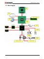
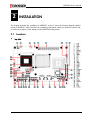
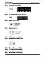
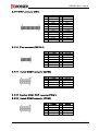
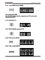
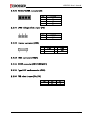
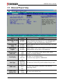
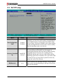
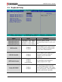
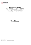
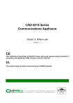
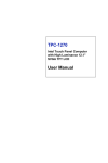
AR-B5230 User’s Manual AR-B5230 CPU Board EPIC form factor, onboard VGA, LVDS with DDR-SODIMM Built in two LAN, CF type-II Edition: 1.01 Book Number: AR-B5230-07.10.15 1/24 AR-B5230 User’s Manual © Copyright 2006 All Rights Reserved. Manual’s first edition: October 31, 2006 For the purpose of improving reliability, design and function, the information in this document is subject to change without prior notice, which does not represent a commitment on the part of the manufacturer. In no event will the manufacturer be liable for direct, indirect, special, incidental, or consequential damages arising out of the use or inability to use the product or documentation, even if advised of the possibility of such damages. This document contains proprietary information protected by copyright. All rights are reserved. No part of this Manual may be reproduced by any mechanical, electronic, or other means in any form without prior written permission of the manufacturer. 2/24 AR-B5230 User’s Manual Contents 1 INTRODUCTION.............................................................. 4 1.1 1.2 1.3 SPECIFICATIONS ......................................................................... 4 WHAT YOU HAVE ...................................................................... 6 BLOCK DIAGRAM ....................................................................... 7 INSTALLATION ................................................................ 8 2.1 2.2 LOCATIONS .............................................................................. 8 LIST OF CONNECTORS AND JUMPER SETTINGS .................................. 10 BIOS SETTING............................................................... 15 3.1 3.2 3.3 3.4 3.5 3.6 3.7 MAIN SETUP ........................................................................ 16 ADVANCED CHIPSET SETUP .......................................................... 17 PNP/PCI SETUP ...................................................................... 18 PERIPHERALS SETUP ................................................................... 19 PC HEALTH SETUP .................................................................... 20 BOOT SETUP ........................................................................... 21 EXIT SETUP ........................................................................... 22 3/24 AR-B5230 User’s Manual 1 INTRODUCTION Welcome to the AR-B5230 EPIC board. The AR-B5230 incorporates the advanced Intel® 915GM Chipset. It supports the Pentium M and Celeron M processors, while coming with a 400/533MHz Front Side Bus. 1.1 Specifications CPU: Socket for Intel uFC-PGA 478 for Pentium M, Celeron M, Coolers required Support CPU type: CM-1.3G/400/512K/PGA(320) CM-1.5G/400/1M/PGA(370) PM-1.6G/400/1M/PGA PM-2.0G/533/2M/PGA(760) PM-1.8G/400/2M/PGA(745) BIOS: AWARD System Chipset: Intel 915GME + ICH6M (915GM for AR-B5230SD) Syetem Memory: One SO-DIMM socket support 400/533 MHz DDR2 SDRAM up to 1GB Graphic controller: Internal Intel 82915GME integrated GMA 900 graphic controller VGA Memory: Intel DVMT 3.0 supports Max 128 MB shared video memory Display mode: CRT (always on) DVII LCD : Dual Channel 18-bits LVDS Interface TV-out: (AR-B5230SD only) Audio: AC’97 Audio out/Audio in/Mic in Ethernet: Intel 82562EZ 10/100Mbps LAN PHY Intel 82551QM 10/100Mbps (defaul) / Intel 82541PI Giga LAN controller Storage: One PATA One SATA One CF: Compact Flash Type-II support UDMA Serial port: One RS232 (COM1) One RS232/422/485 (COM2) Two RS232 (COM3, COM4) 4/24 AR-B5230 User’s Manual USB: Two external ports Two internal ports PCI-104 slot: PS/2: One PS/2 connector for keyboard and mouse GPIO: 8 bit GPIO Watch dog: Software programmable 1~63 Seconds Hardware monitor: CPU voltage CPU and System temperature CPU/System Fan speed control: AT : 12V single voltage input (BIOS default) ATX: Power switch pin header and pin header for external 5VSB input Battery: Lihium Battery, 3V/220mAH OS: Win XP, Win XP Embedded, Win CE, Linux Dimension: 115mm x 165mm (4.528 x 6.496 inches) Operating Temperature: 0~60oC (32~140oF) Storage Temperature: -20~80oC (-4~176oF) Relative Humidity: 0 to 90% @ 40°C, non-condensing (95% @ 40°C, Non-Condensing by request) EMC: CE, FCC Class A 5/24 AR-B5230 User’s Manual 1.2 What You Have Before you begin to install your AR-B5230 board, please make sure that the following items are inside the AR-B5230 package. z z z z z z z z z z z z z The quick manual AR-B5230 board Software utility CD Fan module Power cable for AT Power cable for ATX COM port cable KB/MS cable 40/44 pin IDE connector USB cable Audio cable SATA cable TV out cable (AR-B5230SD only) x1 x1 x1 x1 x1 x1 x2 x1 x1 x1 x1 x1 x1 6/24 AR-B5230 User’s Manual 1.3 Block Diagram 7/24 AR-B5230 User’s Manual 2 INSTALLATION This chapter describes the installation of AR-B5230. At first, it shows the Function diagram and the layout of AR-B5230. It then describes the unpacking information which you should be careful with, as well as the jumper/switch settings for the AR-B5230 configuration 2.1 Locations z Top Side 8/24 AR-B5230 User’s Manual z Buttom Side 36. JP8,JP9 9/24 AR-B5230 User’s Manual 2.2 List of Connectors and Jumper Settings 2.2.1 2.2.2 Power input (CN4) SET 1 SIGNAL +12V 2 GND ATX function connector (CN5) SET 1 2 PS_ON 3 +5V_SUS 2.2.3 CPU fan (FAN1) 2.2.4 CPU select jumper (JP7) 2.2.5 SIGNAL GND SET SHORT SIGNAL DOTHAN OPEN BANINES PCI-104 support SERIRQ (JP6) Note: Short this jumper in order to support SERIRQ function. 2.2.6 Standard PCI-104 connector (PCI104) Note: When using AR-B1045, there will have interfere with SATA1 connector. 2.2.7 Standard SATA connector (SATA1) 2.2.8 44 pin PATA connector (IDE1) 10/24 AR-B5230 User’s Manual 2.2.9 Internal USB connector (USB2) PIN 1 3 5 7 9 2.2.10 SIGNAL +5V USB0USB0+ GND GND PIN 2 4 6 8 10 SIGNAL +5V USB1USB1+ GND GND CF card Master/Slave select jumper (JP4) SET SHORT SIGNAL MASTER OPEN SLAVE 2.2.11 CMOS clear jumper (JP1) 2.2.12 Keyboard lock (J3) 2.2.13 RTC battery connector (CN1) 2.2.14 Keyboard/Mouse connector (KM1) KM 1 2 3 4 5 6 KDT MDT GND VCC KCLK MCLK 1 3 5 2 4 6 Front View 2.2.15 External USB connector (USB1) 2.2.16 10/100 LAN connector (LAN2) 2.2.17 10/100 LAN connector (LAN1) 2.2.18 Standard VGA connector (VGA1) 11/24 AR-B5230 User’s Manual 2.2.19 DVI-D connector (DVI1) PIN 1 2 3 4 5 6 7 8 9 10 11 12 13 SIGNAL GND TD0TD1+ GND TD2TCK+ HPD VCC RED GREEN BLUE VSYNC HSYNC PIN 26 25 24 23 22 21 20 19 18 17 16 15 14 SIGNAL TD0+ GND TD1TD2+ GND TCKSCL1 SDATA1 GND GND GND SCL2 SDATA2 PIN 1 3 5 7 9 11 13 SIGNAL Y-G GND CVBS/Pb-G GND C/Pr-G GND GND PIN 2 4 6 8 10 12 14 SIGNAL N/A N/A N/A N/A N/A N/A N/A PIN 2 4 6 8 SIGNAL /DSRB /RTSB /CTSB /RIB PIN 2 4 6 8 SIGNAL /DSRB /RTSB /CTSB /RIB 2.2.20 V-out connector (TVCON1) 2.2.21 Internal COM2 connector (COM2) PIN 1 3 5 7 9 SIGNAL /DCDB RXDB TXDB /DTRB GND 2.2.22 Stardard COM1 DB-9 connector(COM1) 2.2.23 Internal COM3 connector (COM3) PIN 1 3 5 7 9 SIGNAL /DCDB RXDB TXDB /DTRB GND 12/24 AR-B5230 User’s Manual 2.2.24 Internal COM4 connector (COM4) PIN 1 3 5 7 9 SIGNAL /DCDB RXDB TXDB /DTRB GND PIN 2 4 6 8 SIGNAL /DSRB /RTSB /CTSB /RIB 2.2.25 System FAN (FAN2) Note: The FAN will start to work when temperature over 67ºC and stop when temperature below 53ºC. 2.2.26 Switch button (J1) SET 1-2 SIGNAL SPEAKER 3-4 RESET 5-6 POWER BOTTERN 2.2.27 RS232/422/485 select jumper (JP2) SET 1-2 SIGNAL RS232 3-4 RS422 5-6 RS485 2.2.28 GPIO connector (GPIO1) PIN 1 3 5 7 9 SIGNAL GPIO0 GPIO1 GPIO2 GPIO3 GND PIN 2 4 6 8 10 SIGNAL VCC GPIO7 GPIO6 GPIO5 GPIO4 PIN 1 3 5 7 9 11 13 15 SIGNAL LINE OUT R GND LINE IN R GND N/A GND N/A N/A PIN 2 4 6 8 10 12 14 16 SIGNAL LINE OUT L N.A LINE IN L N.A MIC IN GND N/A N/A 2.2.29 Audio connector (AUDIO1) 13/24 AR-B5230 User’s Manual 2.2.30 RS422/RS485 connector (J2) SET 1 SIGNAL TX+ 2 TX- 3 RX+ 4 RX- 2.2.31 LVDS voltage select jumper (JP5) SET 1-2 SIGNAL 3.3V 2-3 5V 2.2.32 Interver connector (CN3) PIN 1 3 5 SIGNAL +12V GND GND PIN 2 4 6 SIGNAL +12V +5V NC 2.2.33 LVDS connector (LVDS1) 2.2.34 DDR2 connector (DDR2SODIMM1) 2.2.35 Type II CF card connector (CN2) 2.2.36 FSB select jumper (JP8/JP9) FSB 100MHz 133MHz JP8 2-3 2-3 JP9 1-2 2-3 14/24 AR-B5230 User’s Manual 3 BIOS SETTING This chapter describes the BIOS menu displays and explains how to perform common tasks needed to get up and running. It also gives detailed explanation of the elements found in each of the BIOS menus. The following topics are covered: z z z z z z z Main Setup Advanced Chipset Setup Peripherals Setup PnP/PCI Setup PC Health Setup Boot Setup Exit Setup 15/24 AR-B5230 User’s Manual 3.1 MAIN SETUP Once you enter the AwardBIOS™ CMOS Setup Utility, the Main Menu will appear on the screen. Use the arrow keys to highlight the item and then use the <Pg Up> <Pg Dn> keys to select the value you want in each item. Note : Listed at the bottom of the menu are the control keys. If you need any help with the item fields, you can press the <F1> key, and it will display the relevant information. Option Choice Description Date Setup N/A Set the system date. Note that the ‘Day’ automatically changes when you set the date Time Setup N/A Set the system time IDE Channel 0 Master/Slave N/A The onboard PCI IDE connectors provide 1 channel for connecting up to 2 IDE hard disks or other devices. The first is the “Master” and the second is “Slave”, BIOS will auto-detect the IDE type. Halt On All Errors, No Errors, All but keyboard. Select the situation in which you want the BIOS to stop the POST process and notify you. 16/24 AR-B5230 User’s Manual 3.2 Advanced Chipset Setup Option Choice Description Quick Power On Self Test Enabled Disabled This category speeds up Power On Self Test (POST) after you have powered up the computer. If it is set to Enable, BIOS will shorten or skip some check items during POST. Full Screen Logo Show Enabled Disabled Select Enabled to show the OEM full screen logo if you have add-in BIOS. USB Keyboard Support Enabled Disabled Select Enabled if your system contains a Universal Serial Bus (USB)controller and you have a USB keyboard.. On-Chip Frame Buffer Size 1Mb 8Mb Boot Display Panel Type CRT LCD CRT+LCD TV 800x600, 1024x768, 1280x1024 DVMT mode FIXED DVMT Both DVMT/FIXED Memory Size 64Mb 128Mb This Item is for setting the Frame Buffer (Share system memory as display memory). This Item is to set display device TV function only support on AR-B5230SD This Item can Set the LVDS panel resolution that you want This item sets the mode for dynamic video memory technology (DVMT). This item sets the DVMT size 17/24 AR-B5230 User’s Manual 3.3 PnP/PCI setup Option Reset Configuration Data Resources Controlled By IRQ Resources Choice Description Enabled Disabled Normally, you leave this field Disabled. Select Enabled to reset Extended System Configuration Data (ESCD) when you exit Setup. If you have installed a new add-on and the system reconfiguration has caused such a serious conflict, then the operating system can not boot. Auto(ESCD) Manual The Award Plug and Play BIOS has the capacity to automatically configure all of the boot and Plug and Play compatible devices. However, this capability means absolutely nothing unless you are using a Plug and Play operating system such as Windows 95. If you set this field to “manual,” then you may choose specific resources by going into each of the submenus. N/A When resources are controlled manually, assign a type to each system interrupt,depending on the type of the device that uses the interrupt 18/24 AR-B5230 User’s Manual 3.4 Peripherals Setup Option Choice Description Onboard Serial Port 1 Onboard Serial Port 2 Onboard Serial Port 3 Onboard Serial Port 4 Serial Port 1: 3F8 / IRQ4 Serial Port 2: 2F8 / IRQ3 Serial Port 3: 3E8 / IRQ11 Serial Port 4: 2E8 / IRQ10 Select an address and the corresponding interrupt for each serial port USB Controller Enabled Disabled Select Enabled if your system contains a Universal Serial Bus (USB)controller and you have USB peripherals USB 2.0 Controller Enabled Disabled Select Enabled if your system contains a Universal Serial Bus (USB) 2.0 controller and you have USB peripherals AC97 Auido Function Enabled Disabled Audio/Modem Onchip IDE DEVICE Enabled Disabled This item allows you to decide to enable/disable AC97 Audio The integrated peripheral controller contains an IDE interface with support for two IDE channels. Select Enabled to activate each channel separately. 19/24 AR-B5230 User’s Manual 3.5 PC Health Setup This section shows the parameters in determining the PC Health Status. These parameters include temperatures, fan speeds, and voltages. 20/24 AR-B5230 User’s Manual 3.6 Boot setup Option Choice First / Second / Third Boot Device/Other Boot Device Hard Disk CDROM USB-FDD USB-CDROM LAN Disabled LAN Boot Select Enabled Disabled Hard Disk Boot Priority N/A Description The BIOS attempts to load the operating system from the devices in the sequence selected in these items. These fields allow the system to search for an OS from LAN These fields set the Boot Priority for each Hard Disk 21/24 AR-B5230 User’s Manual 3.7 Exit SETUP Option Save & Exit Setup Load Optimized Defaults Choice Description Press “Y” to store the selections made in the menus in CMOS – a special section Pressing <Enter> on this item of memory that stays on after you turn for confirmation: your system off. The next time you boot your computer, the BIOS configures your Save to CMOS and EXIT system according to the Setup selections (Y/N)? Y stored in CMOS. After saving the values the system is restarted again When you press <Enter> on this item you get a confirmation dialog box with Press ‘Y’ to load the default values that are factory-set for optimal-performance a message like this: system operations. Load Optimized Defaults (Y/N) ? N Exit Without Saving Pressing <Enter> on this item This allows you to exit Setup without storing any changes in CMOS. The for confirmation: previous selections remain in effect. This Quit without saving (Y/N)? shall exit the Setup utility and restart your Y computer. Set Password When a password has been enabled, Pressing <Enter> on this item you will be prompted to enter your for confirmation: password every time you try to enter Setup. This prevents unauthorized ENTER PASSWORD: persons from changing any part of your 22/24 AR-B5230 User’s Manual system configuration. Type the password, up to eight characters in length, and press <Enter>. The password typed now will clear any previous password from the CMOS memory. You will be asked to confirm the password. Type the password again and press <Enter>. You may also press <Esc> to abort the selection and not enter a password. To disable a password, just press <Enter> when you are prompted to enter the password. A message will confirm that the password will be disabled. Once the password is disabled, the system will boot and you can enter Setup freely. 23/24 AR-B5230 User’s Manual 24/24