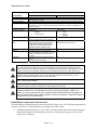
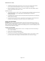
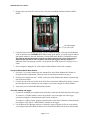
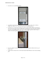
1
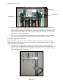
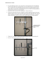
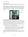
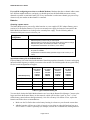
Radio Modem (Part # C-002 and C-003) Operation Manual
The Radio Modem (Part # C-002) and Base
Station (Part # C-003) allow for wireless
communication with a deployed HOBO®
Weather Station or Micro Station (H21) logger.
Using a Radio Modem Base Station plugged
into the computer’s COM port, you can contact
the Radio Modem wirelessly, giving you the
ability to launch, read out, and check the status
of a remote H21 logger from your home or
office. The Radio Modem is designed to be
mounted on the same mounting pole or tripod
mast used with the H21 logger, making setup
convenient and easy.
900 MHz Radio Modem System
Specification
Radio Frequency
Radio Type
Antenna
Modem Communications
Rate
Transmitter Power
Receiver Sensitivity
Antenna Gain
Operating Temperature
Range
Environmental Rating
Power
Battery Life
Weight
Dimensions
Regulatory Compliance
Radio Modem
Base Station
902 to 928 MHz, unlicensed ISM Band
MaxStream™ 9XStream frequency hopping spread spectrum transceiver with 7 different
hopping sequences through 25 channels. See www.maxstream.net for full radio specifications.
½ Wave Whip Antenna (also see Accessories below)
19200 bps (max) throughput. May vary depending on signal quality
100 mW
-107dBm
½ Wave Whip Antenna: 2.1dBi
4 Element Yagi (optional accessory C-ANT-1): 8.2 dBi
-20° to 50°C (-4° to 122°F), with Alkaline
0 to 70° C (32° to 158°F)
Batteries
-40° to 70°C (-40° to 158°F) with customer
supplied DC power supply
Weatherproof
Indoor use only, non-condensing, non-fogging
6 alkaline D cells (included); connector for
9V, 400 mA DC power adapter (2.1 mm ID
[positive] 5.5 mm OD [negative]) (included)
user-supplied 400 mA DC Power adapter (2.1
mm ID [positive] 5.5 mm OD [negative]),
minimum 6V, maximum 10V
Varies with temperature, data logging rate
NA
(bytes/day) and frequency of connections.
Typically provides 1 year of service when
offloading daily or weekly and up to 10 months
of service when offloading hourly. Battery life
may be significantly reduced when used at
temperatures below freezing. (See Table 1for
more details).
2.1 kg (4.6 lbs) including D batteries
233 g (0.5 lbs)
14.6 x 22.2 x 5.7 cm (5.75 x 8.75 x 2.25
14 x 7 x 3 cm (5.5 x 2.8 x 1.2 inches) not
including antenna
inches) not including mounting plate or
antenna
Complies with Part 15 of the FCC Rules. Operation is subject to the following two conditions: (1)
this device may not cause harmful interference and (2) this device must accept any interference
© 2003 Onset Computer Corporation
Part #: MAN-C-003
Doc #: 8159-A
Radio Modem User’s Guide
900 MHz Radio Modem System
Specification
Logger Compatibility
Functional Range
Network Size
Operational Indicators
Battery Voltage Out
Serial Communications
Cable
Enclosure Access
Mounting
Accessories
Radio Modem
Base Station
received, including interference that may cause undesired operation. Approved for use in the
United States and Canada.
H21-001 and H21-002 (H21-002 requires Micro Station Adapter Cable Part # CABLE-HWS-F)
Typically 3–5 km (2–3 miles) line of sight, or 150–300 m (1/8–1/4 mile) non-line of sight. Range
increases to 5–7 km (3–5 miles) with optional Yagi antennas (for more info, see Operational
Range on page 5)
At least seven units per location supported (see Multiple Radio Modems on page 11)
Status LEDs:
Status LEDs:
•
Radio On
•
Power
•
Receiving Data
•
Data In
•
Data Out
Screw-terminal connector allows for a voltage
NA
sensor connection (10K output impedance)
1 meter (3.3 ft) weatherproof cable connects
2 m (6.6 ft) RS232 DB9 M/F Serial Cable
connects to computer serial port
to the external communications port on the
HOBO Weather Station and HOBO Micro
Station (H21-002 requires Micro Station
Adapter Cable Part # CABLE-HWS-F)
Cover secured by six screws
NA
Clamps to mast of 4.1 cm (1.6 inches)
NA
maximum diameter with included U-bolts and
clamps or vertical surface with screws (not
included)
900 MHz 4-Element Yagi Antenna (Part # CNA
ANT-1)
Grounding Kit (Part # M-GKA)
WARNING: Severe shock hazard. Before installing any HOBO Weather Station or Micro Station tripod
or mounting pole, ensure that there are no electrical power lines overhead. Do not install the system
during any atmospheric electrical activity. Do not assemble or transport tripods, mounting poles, or other
structures unless there is sufficient clearance from potential electrical sources or other obstructions.
WARNING: Do not climb on or around the HOBO Weather Station or Micro Station tripod. The HOBO
Weather Station and Micro Station and any of its associated hardware, towers, poles, etc. are not
designed to support the weight of a person. Injury may result.
WARNING: If using stakes to stabilize the tower or grounding rod, ensure that there are no underground
wires or pipes before installation.
WARNING: Electrical hazard. Make sure the HOBO Weather Station or Micro Station is properly
grounded to reduce the chance of damage from electrical storms and activity.
WARNING: This equipment is approved only for mobile and base station transmitting devices,
separation distances of (i) 20 centimeters or more for antennas with gains < 6dBi or (ii) 2
meters or more for antennas with gains ≥ 6dBi should be maintained between the antenna of
this device and nearby persons during operation. To ensure compliance, operation at distances
closer than this is not recommended.
Radio Modem components and accessories
The Radio Modem Communications System works with H21 loggers only. The following components are
required to add wireless communications to an existing or new H21 system:
•
900 MHz Radio Modem (Part # C-002). This is a wireless modem that is connected to the logger.
Data from the logger is then transmitted wirelessly, via radio antenna signal, to a base station
connected to a computer.
Page 2 of 15
Radio Modem User’s Guide
•
900 MHz Radio Modem Base Station (Part # C-003). This is the component that sends and
receives data from the Radio Modem. It connects to the computer via COM port.
•
Remote Site Manager software (Version 1.1 or greater) with PC cable (Part # RSM), which is
included with the Base station (Part # C-003)
Optional accessories:
•
Yagi antenna kit (Part # C-ANT-1). This is a directional antenna with higher gain that can be used
in place of the built-in 1/2 wave whip antenna on the Radio Modem to increase the
communication range.
•
Grounding Kit (Part # M-GKA) required if using the optional Yagi antenna kit or any third-party
antenna, otherwise optional.
•
Guy Wire Kit (Part # M-GWA) may be appropriate for some locations to avoid vibrations and
oscillations when deploying the system where winds will be 30 MPH or greater.
Setting up the Radio Modem
IMPORTANT: Before mounting the Radio Modem with the H21 logger and deploying it outside, you
must first configure the Radio Modem for wireless communication. This involves assigning channel and
address numbers to the Radio Modem using Remote Site Manager software, and then completing a bench
test with the Radio Modem Base Station.
Configure the Radio Modem
1. Install the Remote Site Manager software, version 1.1 or higher (see the Remote Site Manager
User’s Guide for details).
2. Unscrew the cover from the Radio Modem.
3. Insert the six D-cell batteries, observing polarity.
4. Connect the PC cable (included with Remote Site Manager software) to the computer’s COM
port. Ensure that the cable coming out of the Radio Modem is not connected to a logger.
Page 3 of 15
Radio Modem User’s Guide
5. Plug the other end of the PC cable into the serial jack on the Radio Modem (labeled COMM
PORT).
PC cable plugged
into comm. port
6. Using the Remote Site Manager software, set up a remote site profile, selecting a Radio Modem
as the connection route. IMPORTANT: When setting up the profile, you must assign an address
and channel number to the radio modem by clicking the Remote Module Configuration button.
The address and channel number must be set before operating the system, otherwise the
Radio Modem will not be able to transfer data from the logger to the base station. For
additional details on setting up a profile, see the Quick Start in the Remote Site Manager User’s
Guide.
7. Once configured, unplug the PC cable from the Radio Modem and from the computer.
Set up the Radio Modem Base Station
1. Screw the ½ wave whip antenna into the Antenna Port on the Radio Modem Base Station. If
using the optional Yagi antenna, follow the steps for mounting the antenna on page 8.
2. Plug the power adapter into the 7-18VDC jack on the Radio Modem Base Station, and then plug
into an electrical outlet.
3. Connect one end of the serial cable to the Serial Port on the Radio Modem Base Station. Connect
the other into the same COM port on the computer you used to configure the Radio Modem.
4. Turn on the power on the Radio Modem Base Station.
Test radio modem with logger
1. Connect the weatherproof communications cable that is built into the Radio Modem to the logger.
To connect to a Weather Station, remove the protective cap on the right side of the logger
enclosure and plug the communications cable into the connector.
To connect to a Micro Station, plug the communications cable into the External Communications
Port Adapter Cable (Part # CABLE-HWS-F) attached to the logger.
2. Use the Remote Site Manager software to contact the logger using the profile you created when
you configured the Radio Modem. Make sure the channel and address for the base station match
Page 4 of 15
Radio Modem User’s Guide
those for the Radio Modem connected to the logger. For instructions on using the software, see
the Remote Site Manager User’s Guide.
3. If you will be deploying multiple Radio Modems with a single base station, you should verify
communication with each of them to ensure there are no channel or address conflicts.
If you have trouble contacting the logger, refer to Troubleshooting on page 13.
Mounting/assembly instructions
Before you begin
IMPORTANT: You must complete the steps in Setting up the Radio Modem before completing these
instructions. The Radio Modem must be configured as described in the previous section before it is
deployed.
Tools required
•
Medium sized Phillips head screwdriver
•
1/2 inch wrench
•
3/4 inch open-ended wrench or 8–10 inch adjustable wrench
•
Cutters for trimming the zip ties
Operational range
The operational range for the radio modem system varies depending on where you place the logger and
radio modem. The range is typically 2 to 3 miles line of sight, 400m (1/4 mile) non-line of sight. Range
may be increased further with optional Yagi antennas. When selecting a location to deploy the logger and
radio modem, factor in both the distance between the radio modem and base station and the environment
in that distance. You can optimize the reception in marginal locations by doing the following:
•
Move the antennas to get a true line of sight. Trees, hills, buildings, and other obstructions will
interfere with radio reception. Even a single tree or obstruction can significantly reduce signal
quality and range.
•
Place the antennas as high as possible. It may be necessary to use a taller mast and/or longer cable
lengths to obtain optimum range.
•
Use a higher gain antenna such as a Yagi directional antenna instead of the ½ wave whip antenna.
•
Mount the base station with its antenna in a window facing the station. Radio waves will go
through the glass better than building walls. If necessary, you can add a serial extension cable
between the PC serial port and the 2 m (6.6 ft) RS232 DB9 M/F Serial Cable that connects to the
base station. (Note: RS232 may not function properly at distances exceeding 15 m (15 ft).
•
Mount the base station antenna outside the building using as short an extension cable as possible.
You will need to provide your own extension cable.
•
Mount antennas away from metallic objects to avoid interference. Metallic objects should be at
least half a wavelength (10 cm [6 inches]) away from the sides of the antenna. No metallic objects
should be in front of the antenna (between the antenna and the base station/Radio Modem).
•
Both the base station antenna and the Radio Modem antenna should have the same polarization.
For example, if the Radio Modem antenna is vertical, then the base station’s antenna should also
be mounted vertically. This is normal operation when the Radio Modem is mounted on a pole. If
you are using the Yagi antenna, the grey PVC part should be mounted up and the whip antenna at
Page 5 of 15
Radio Modem User’s Guide
the base station should be mounted up. If the Yagi is mounted sideways (elements are parallel to
the ground), then the whip antenna on the base station should also be oriented parallel to the
ground.
Not all sites will work. In some cases the only solution may be to move the radio modem closer to the
base station or to a better location (i.e. higher or direct line of sight).
Once the logger data is downloaded via radio modem, you have the option of sending the data to others
automatically. This can be done by configuring the Remote Site Manager software to send logger via
email or FTP. This requires a connection to the Internet. For details on setting up email and FTP data
transfer and the minimum requirements needed, see the Remote Site Manager User’s Guide.
Note: The Radio Modem and Base Station may interfere with the operation of 900 MHz cordless phones,
computer speakers, and other electronic devices.
Steps for mounting Radio Modem
Radio Modem
Tools required
• Medium sized Phillips Head screwdriver
•
1/2 inch open-ended wrench
Before choosing the site where you will be installing the logger, Radio Modem, and antenna, read the
mounting guidelines in the Operational Range section on page 5.
1. Make sure the batteries are installed correctly in the Radio Modem
2. Place the two desiccant packs inside the Radio Modem body.
Page 6 of 15
Radio Modem User’s Guide
3. Screw the cover onto the Radio Modem.
4. Assemble the tripod and mount the logger. See the HOBO Weather Station User’s Guide or
HOBO Micro Station User’s Guide for instructions on assembling the tripod.
5. Using the two 1-5/8 inch U-bolt assemblies provided, mount the Radio Modem on the mast just
above or below the logger enclosure. Note: When assembling the U-bolts, place them around the
upper mast, and install the saddle clamp. Place the Radio Modem against the saddle clamps as
shown in the following photo and hand-tighten the U-bolt nuts.
6. If you are using the Guy Wire Kit, position the radio modem so that it will not be in the way of
the guy wires.
7. Tighten all four U-bolts with a 1/2 inch wrench until the Radio Modem is secure on the mounting
pole.
Page 7 of 15
Radio Modem User’s Guide
8. A weatherproof communications cable is attached to the side of the Radio Modem. Take the other
end of this cable and plug it into the side of the logger. Twist the collar of the connecter
clockwise to lock it into place.
Weatherproof
communications
cable attached to
the Radio Modem
Plug the other
end of the
communications
cable into the
side of the logger
Steps for mounting Yagi antenna
IMPORTANT: The HOBO Weather Station or Micro Station must be grounded before installing the Yagi
antenna (use Grounding Kit, Part # M-GKA) or an equivalent grounding system.
Tools required
• Medium sized Phillips Head screwdriver
•
5/16 inch open-ended wrench
•
3/4 inch open-ended wrench
•
1/2 inch open-ended wrench
•
Medium-sized pliers
Important: The following steps should be completed before checking modem operation and before the
modem is deployed.
1. Remove the ½ wave whip antenna from the side of the logger. Begin by opening the Radio
Modem and unscrewing the cable from the radio module (a 5/16 inch wrench may be required).
The radio module can be carefully removed by lifting up on it gently. Use a ¾ inch open-end
wrench to remove the nut and lock washer on the inside of the right angle connector on the lefthand side of the box. Carefully feed the cable and connector out from the enclosure. Save this
cable/antenna assembly in case you want to use it in the future.
Page 8 of 15
Radio Modem User’s Guide
Radio module
Antenna port
Coaxial cable
2. Attach the extension cable supplied with your Yagi antenna carefully to the radio module, and
feed the N Bulkhead connector through the case from the inside (make sure that the back o-ring is
in the groove of the connector). Install the lock washer and nut from the outside of the case and
tighten. Double-check that the radio module is firmly installed, and all the pins line up, and then
replace the cover of the Radio Modem.
3. Note: Use a 5/16 inch wrench to gently tighten the coaxial cable connection to the radio module.
The connector can be damaged if it is over-tightened, but it should not be loose either.
Installing the Yagi antenna in the field
Before choosing the site where you will be installing the logger, Radio Modem, and antenna, read the
mounting guidelines in the Operational Range section on page 5. The Grounding Kit (Part # M-GKA) is
required when using a Yagi antenna.
1. Using the inch U-bolt assembly provided, mount the antenna high as possible (typically just
below the cross arm). Note: When assembling the U-bolts, place them around the upper mast, and
install the saddle clamp. Place the antenna against the saddle clamps as shown in the following
photo and hand-tighten the U-bolt nuts.
Page 9 of 15
Radio Modem User’s Guide
2. Screw the lightening protective device into the loose end of the antenna cable. The lightening
protection device then must be mounted firmly on the (grounded) tripod to a U-bolt as shown
above. Attach the other end of the lightening protective device to the Radio Modem using the
supplied RG-213 coaxial cable. The lightening protection device MUST be firmly mounted on
the (grounded) tripod for it to function properly.
3. If practical, test the system now before applying the weatherproofing tape.
4. Take the butyl rubber tape and wrap it completely around the lightening protection device and
attached connectors. Then, use the vinyl black tape and wrap all the butyl rubber tape. This will
form a watertight seal around the connectors and the lightening protection device. The butyl
rubber and vinyl tape can also be used to seal the coaxial connection to the Radio Modem
Vinyl tape surrounding
butyl rubber tape on
lightning protection
device
5. Tighten the U-bolt with a 1/2 inch wrench until the antenna is secure on the mounting pole.
6. Secure the cable along the tripod with tie wraps.
Tie wrap
Page 10 of 15
Radio Modem User’s Guide
Radio Modem operation
Once the Radio Modem is installed, use the Remote Site Manager software to connect to the logger. For
complete instructions on connecting to the logger via Radio Modem, see the Remote Site Manager User’s
Guide.
There are two lights inside the Radio Modem that serve as operational indicators (see below). The Power
light (labeled POWER/TX) indicates the Radio Modem is powered up. The Connected light (labeled RX)
indicates the Radio Modem is sending or receiving information from the Radio Modem Base Station.
During normal operation the Power/Tx light will flash every 16 seconds. This happens when the Radio
Modem “wakes up” and checks to see if a base station is trying to contact it. When the Radio Modem
wakes up, the Power/Tx light will be on most of the time and will flicker when the Radio Modem is
transmitting.
Power On light
Connected light
Multiple Radio Modems
You can deploy multiple Radio Modems, each connected to a logger, as a network. Only one base station
is required for contacting multiple Radio Modems. When configuring the Radio Modem with Remote Site
Manager, a channel and address is assigned to the Radio Modem. These numbers make it identifiable on
the network by the base station. The channel can be any number from 1 to 7 and the address can be any
number from 1 to 65535. In theory, the maximum network size could be quite large (the maximum
number of channels multiplied by the maximum number of addresses, or 7 X 65535). In reality, however,
there are limitations to the number of Radio Modems and loggers you can deploy. There are two factors
that affect how many systems you can expect to deploy successfully:
•
How often you will be calling each Radio Modem. The more frequently you contact a Radio
Modem, the less time it leaves to contact other Radio Modems.
•
How many Radio Modems are using the same channel. Any time you contact one Radio Modem
on a certain channel, all other Radio Modems on the same channel wake up, which depletes the
battery life more quickly. For example, when two multiple radio modems are on the same
channel, you will be calling each twice as often as you would if each had their own channel,
which can lead to battery depletion twice as quickly as normal.
If you will be configuring more than one Radio Modem, but less than seven: Each modem should
have a different channel number and any module address. This will prevent multiple modems with the
same channel from powering up when a given modem on that channel is contacted and will maximize
battery life.
Page 11 of 15
Radio Modem User’s Guide
If you will be configuring more than seven Radio Modems: Modems that share a channel address must
have different module addresses, and again you should spread out the Radio Modems across as many
channels as possible to maximize battery life. Every modem that is on the same channel gets powered up
whenever any one modem on that channel is contacted.
Batteries
Choosing a power source
The Radio Modem can be powered by either batteries or a user-supplied 9V DC adapter. Battery power
consists of six D alkaline batteries. If you use an external power supply, the batteries can remain in the
Radio Modem and function as a backup to the external power supply. Use the following table to
determine which power source is best for you.
Battery/power source
configuration
Recommended for use when:
D alkaline batteries
•
Offload frequency is twice a day or less frequent
•
Offload frequency is hourly and you have access to the system to change
batteries every five to ten months (see Table 1 next page)
•
Temperatures are between -20° to 50°C (-4°F to 122°F)
•
Offload frequency is hourly or more frequently
•
AC power is available
•
Temperatures exceed the battery operation range of -20° to 50°C (-4° to
122°F)
External 9V DC
Approximate battery life of the Radio Modem
Expected battery life varies based on the amount of data being transferred (number of sensors and logging
interval) and the frequency at which you connect to the modem. The following table shows typical battery
life for several configurations of loggers.
Offload Frequency
H21-00x with
four 10-bit
sensors
1 minute
logging
interval
H21-00x with
ten 10-bit
sensors
1 minute
logging
interval
H21-00x with
four 10-bit
sensors
15 minute
logging
interval
H21-00x with
ten 10-bit
sensors
15 minute
logging
interval
5 minutes
2 months
2 months
NA
NA
15 minutes
5 months
4 months
6 months
5 months
1 hour
7 months
5 months
10 months
8 months
12 hours
8 months
6 months
12+ months
12+ months
Table 1: Typical modem battery life
You can check whether the Radio Modem batteries are low with the Remote Site Manager. Connect to the
logger and check the Remote Battery on the status tab, which will list either “good” or “low.” A “low”
remote battery status indicates that approximately 10 to 20% of battery life remains. If low, replace the
batteries and follow these recommendations:
•
Make sure the Use Before date on the battery housing is at least two years from the current date.
•
Alkaline batteries will lose up to 10% of capacity a year sitting on a hot shelf and can lose up to
50% or more if “cooked” repeatedly (for example, if stored on a car dashboard). Placing batteries
Page 12 of 15
Radio Modem User’s Guide
in the refrigerator can reduce self-discharge to 1 to 2% per year, but they should be protected so
that condensation does not form on the batteries.
•
Check and if necessary replace the H21 logger batteries. Note: The logger and Radio Modem’s
power supplies are independent and both should be checked and changed as required.
Battery voltage sense terminals
The modem has screw terminals for measuring the primary battery voltage (D cells or 9V input). This
terminal has a 10K output impedance and is not suitable for powering any external devices. Total voltage
for six fresh D cell batteries is 9.0 to 9.6 volts. Replace the batteries when the total voltage for all six D
cells is 6.0 to 6.6 volts.
Maintenance
The Radio Modem enclosure should not require regular cleaning. However, in the event that it becomes
dusty inside the enclosure, you can blow it out with compressed air. Do not allow water inside the
enclosure. In the event that moisture gets into the enclosure, carefully dry it out with a fan or lamp (do not
use a heat gun).
In addition, as part of regular H21 logger maintenance, you should periodically check the system and
make sure all screws and bolts are tightly secured.
Replace the batteries on a regular basis using the above battery life chart as a guide. You may need to use
a screwdriver to gently pry the D cell batteries out of their holders when replacing them.
The desiccant pack included with the Radio Modem is an indicating desiccant pack, which means it
changes color from bright blue to light pink when it is no longer absorbing moisture. If the desiccant pack
is blue, it is still good. If it is pink, it needs to be reconditioned or replaced. To recondition a desiccant
pack, place it in a warm, dry spot until it turns blue. For example, place the desiccant pack in an oven set
to 50 to 70°C (122 to 158°F) for 24 hours. Once it turns blue again, you can place it back in the modem.
If the desiccant pack is light pink, also check for condensation within the modem. If there is condensation,
check that the fittings are still tight and make sure the cover’s gasket is clean and there is no damage to
the Radio Modem housing. If moisture remains a problem, consider moving the modem and logger to a
drier location.
Troubleshooting
Use the following chart to help you resolve problems with the Radio Modem system.
Problem
Cannot connect to the logger at all
Possible Solutions
•
•
•
•
•
•
•
Make sure the Base Station is plugged in and the power is on.
Check that the Base Station is connected to the correct COM port; this
should be the same COM port specified in the Remote Site Manager
profile.
Verify that the Power LED on the Radio Modem is on or flashes at
least every 16 seconds. If not, verify that fresh batteries are installed
properly in the Radio Modem.
Check that the correct channel, address, and sleep time is set in the
profile for the Radio Modem.
Check that the Radio Modem is plugged into the data logger. Also
make sure the logger is not connected directly to the computer with the
PC interface cable.
Make sure that the antennas on both the Base Station and Radio
Modems are connected.
Make sure you are using the correct profile in the Remote Site
Manager to connect to the logger.
Page 13 of 15
Radio Modem User’s Guide
Problem
Possible Solutions
•
•
Cannot connect to the logger at
long range
•
•
•
•
•
•
Connections to the logger are
intermittent
•
•
•
Premature battery failure
•
•
•
Moisture in the modem enclosure
•
•
•
Verify that you can communicate directly with the logger using just the
PC cable. If you cannot, the logger may need new batteries or have
another problem. Consult the logger’s user guide for more details.
Verify that you are using Onset-supplied MaxStream radio modules.
Standard radio modules from MaxStream will not work with the C002/3 system without modification by Onset.
Verify all steps above.
Move antenna(s) so that a line-of-sight condition exists (see
Operational Range section for mounting recommendations).
Increase the height of the antenna(s).
Switch to a higher gain antenna (use a Yagi antenna instead of the
built-in Radio Modem antenna)
Verify the Radio Modem and Base Station antennas have the same
polarization (vertical or horizontal)
Verify that there are no metallic objects within 10 cm (6 inches) of the
antennas
Check for loose connections; tighten and waterproof all external
antenna connections
If the signal seems to be marginal, has something changed at the site?
Vegetation and traffic can block the signal.
Check the sleep time is set correctly. The sleep time set in the Remote
Site Manager profile should match the sleep time in the Radio Modem.
The sleep time may not be optimized. Set the sleep time for 16
seconds for maximum battery life.
The call frequency may be too high. See the Battery Life table on page
12 for more details.
The operating temperature may be too cold. Minimum operational
temperature is -20°C (-4°F). Customer supplied 9V DC source is
required for operation below -20°C (-4°F).
Verify that all thru-hole fittings are snug and in good condition.
Replace desiccant if color has changed from blue to pink.
Check seal on modem cover and tighten all screws.
Warranty
This product is warranted to be free from defects in material and workmanship for a period of one year
from the date of original purchase. During the warranty period, Onset will, at its option, either repair or
replace products that prove to be defective. This warranty is void if the Onset products have been
damaged by customer error or negligence, or if there has been any unauthorized modification.
Support
For support, contact your place of purchase (Onset Computer Corporation or Authorized Onset Dealer),
or visit www.onsetcomp.com or www.hobohelp.com.
Onset Computer Corporation
P.O. Box 3450
Pocasset, MA 02559-3450
470 MacArthur Blvd.
Bourne, MA 02532
Sales: 1-800-LOGGERS (1-800-564-4377)
www.onsetcomp.com
[email protected]
Page 14 of 15
Radio Modem User’s Guide
Returns
Note: Please direct all warranty claims to the place of purchase.
Before returning a failed unit directly to Onset, you must obtain a Return Merchandise Authorization
(RMA) number from Onset. You must provide proof that you purchased the Onset product(s) directly
from Onset (purchase order number or Onset invoice number). Onset will issue an RMA number that is
valid for 30 days. You must ship the product(s), properly packaged against further damage, to Onset (at
your expense) with the RMA number marked clearly on the outside of the package. Onset is not
responsible for any package that is returned without a valid RMA number or for the loss of the package
by any shipping company.
Repair Policy
Products that are returned after the warranty period or are damaged by the customer as specified in the
warranty provisions can be returned to Onset with a valid RMA number for evaluation.
ASAP Repair Policy
For an additional charge, Onset will expedite the repair of a returned product.
© 2003 Onset Computer Corporation. All rights reserved.
Onset and HOBO are registered trademarks of Onset Computer Corporation. MaxStream is a trademark of MaxStream, Inc.
Part #: MAN-C-003
Document #: 8159-A
Page 15 of 15