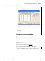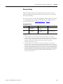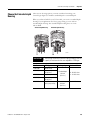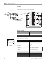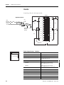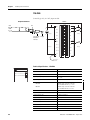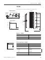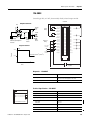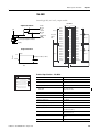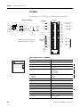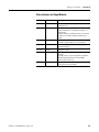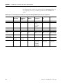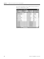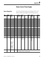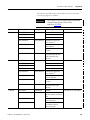
1
ControlLogix Digital I/O Modules Input Modules 1756-IA8D, 1756-IA16, 1756-IA16I, 1756-IA32, 1756-IB16, 1756-IB16D, 1756-IB16I, 1756-IB32, 1756-IC16, 1756-IG16, 1756-IH16I, 1756-IM16I, 1756-IN16, 1756-IV16, 1756-IV32 Output Modules 1756-OA8, 1756-OA8D, 1756-OA8E, 1756-OA16, 1756-OA16I, 1756-OB8, 1756-OB8EI, 1756-OB8I, 1756-OB16D, 1756-OB16E, 1756-OB16I, 1756-OB16IS, 1756-OB32, 1756-OC8, 1756-OG16, 1756-OH8I, 1756-ON8, 1756-OV16E, 1756-OV32E, 1756-OW16I, 1756-OX8I User Manual Important User Information Solid state equipment has operational characteristics differing from those of electromechanical equipment. Safety Guidelines for the Application, Installation and Maintenance of Solid State Controls (publication SGI-1.1 available from your local Rockwell Automation sales office or online at http://www.rockwellautomation.com/literature/) describes some important differences between solid state equipment and hard-wired electromechanical devices. Because of this difference, and also because of the wide variety of uses for solid state equipment, all persons responsible for applying this equipment must satisfy themselves that each intended application of this equipment is acceptable. In no event will Rockwell Automation, Inc. be responsible or liable for indirect or consequential damages resulting from the use or application of this equipment. The examples and diagrams in this manual are included solely for illustrative purposes. Because of the many variables and requirements associated with any particular installation, Rockwell Automation, Inc. cannot assume responsibility or liability for actual use based on the examples and diagrams. No patent liability is assumed by Rockwell Automation, Inc. with respect to use of information, circuits, equipment, or software described in this manual. Reproduction of the contents of this manual, in whole or in part, without written permission of Rockwell Automation, Inc., is prohibited. Throughout this manual, when necessary, we use notes to make you aware of safety considerations. WARNING Identifies information about practices or circumstances that can cause an explosion in a hazardous environment, which may lead to personal injury or death, property damage, or economic loss. IMPORTANT Identifies information that is critical for successful application and understanding of the product. ATTENTION Identifies information about practices or circumstances that can lead to personal injury or death, property damage, or economic loss. Attentions help you identify a hazard, avoid a hazard, and recognize the consequence. SHOCK HAZARD Labels may be on or inside the equipment, for example, a drive or motor, to alert people that dangerous voltage may be present. BURN HAZARD Labels may be on or inside the equipment, for example, a drive or motor, to alert people that surfaces may reach dangerous temperatures. Allen-Bradley, Rockwell Automation, Rockwell Software, Logix5000, RSLogix 5000, RSLogix, RSLogix, ControlLogix, RSNetWorx, RSNetWorx for ControlNet, RSLinx, PowerFlex 700S, Data Highway Plus, and TechConnect are trademarks of Rockwell Automation, Inc. Trademarks not belonging to Rockwell Automation are property of their respective companies. Summary of Changes Introduction This release of this document contains updated information and specifications for ControlLogix digital I/O modules. Documentation Revision This document supersedes the ‘C’ version of 1756-UM058-EN-P. The ‘D’ version was not available to the public. New Information New information is marked by change bars in the side column, as shown to the right. 3Publication 1756-UM058E-EN-P - August 2010 Section Module Information Chapter 2 and page 29 Information for scheduling I/O modules on the ControlNet network and setting up I/O modules to trigger event-based tasks. Chapter 3 and page 143 1756-IA32 module - Features and module-specific information Chapter 3 and page 161 1756-IG16 module - Features and module-specific information Chapter 3 and page 200 1756-OB8I module - Features and module-specific information Chapter 3 and page 212 1756-OB16IS module - Features and module-specific information Chapter 3 and page 221 1756-OG16 module - Features and module-specific information Chapter 3 and page 233 1756-OV32E module - Features and module-specific information Chapter 3 Using electronic keying with examples of Exact Match, Compatible, and Disabled Keying. Chapter 7 New digital I/O specifications. Appendix F Requirements for firmware updates for Major Revision 3.x. Appendix G Updated information on Interface Modules (IFMs) and pre-wired cables that are available with digital I/O modules. 3 Summary of Changes Notes: 4 Publication 1756-UM058E-EN-P - August 2010 Table of Contents Documentation Revision . . . . . . . . . . . . . . . . . . . . . . . . . . . . . . . . . . . . . 3 New Information . . . . . . . . . . . . . . . . . . . . . . . . . . . . . . . . . . . . . . . . . . . 3 Preface Introduction . . . . . . . . . . . . . . . . . . . . . . . . . . . . . . . . . . . . . . . . . . . . . . 11 Who Should Use This Manual. . . . . . . . . . . . . . . . . . . . . . . . . . . . . . . . 11 Additional Resources . . . . . . . . . . . . . . . . . . . . . . . . . . . . . . . . . . . . . . . 11 Chapter 1 What Are ControlLogix Digital I/O Modules? Introduction . . . . . . . . . . . . . . . . . . . . . . . . . . . . . . . . . . . . . . . . . . . . . . 13 Available Features . . . . . . . . . . . . . . . . . . . . . . . . . . . . . . . . . . . . . . 13 I/O Module in the ControlLogix System . . . . . . . . . . . . . . . . . . . . . . . 14 Module Identification and Status Information . . . . . . . . . . . . . . . . . . . 17 Chapter 2 Digital I/O Operation in the ControlLogix System 5Publication 1756-UM058E-EN-P - August 2010 Introduction . . . . . . . . . . . . . . . . . . . . . . . . . . . . . . . . . . . . . . . . . . . . . . 19 Ownership . . . . . . . . . . . . . . . . . . . . . . . . . . . . . . . . . . . . . . . . . . . . . . . 19 Use RSNetWorx and RSLogix 5000 Software . . . . . . . . . . . . . . . . . . . 20 Internal Module Operations . . . . . . . . . . . . . . . . . . . . . . . . . . . . . . . . . 21 Input Modules . . . . . . . . . . . . . . . . . . . . . . . . . . . . . . . . . . . . . . . . . 21 Output Modules. . . . . . . . . . . . . . . . . . . . . . . . . . . . . . . . . . . . . . . . 22 Connections . . . . . . . . . . . . . . . . . . . . . . . . . . . . . . . . . . . . . . . . . . . . . . 23 Direct Connections . . . . . . . . . . . . . . . . . . . . . . . . . . . . . . . . . . . . . 24 Rack Connections . . . . . . . . . . . . . . . . . . . . . . . . . . . . . . . . . . . . . . 24 Suggestions for Rack Connection Usage . . . . . . . . . . . . . . . . . . . . 26 Input Module Operation . . . . . . . . . . . . . . . . . . . . . . . . . . . . . . . . . . . . 27 Input Modules in a Local Chassis . . . . . . . . . . . . . . . . . . . . . . . . . . . . . 27 Requested Packet Interval (RPI) . . . . . . . . . . . . . . . . . . . . . . . . . . . 27 Change of State (COS) . . . . . . . . . . . . . . . . . . . . . . . . . . . . . . . . . . 28 Trigger Event Tasks. . . . . . . . . . . . . . . . . . . . . . . . . . . . . . . . . . . . . 29 Input Modules in a Remote Chassis . . . . . . . . . . . . . . . . . . . . . . . . . . . 29 Remote Input Modules Connected Via the ControlNet Network . . . . . . . . . . . . . . . . . . . . . . . . . . . . . . . . . 29 Remote Input Modules Connected Via the EtherNet/IP Network . . . . . . . . . . . . . . . . . . . . . . . . . . . . . . . 31 Output Module Operation. . . . . . . . . . . . . . . . . . . . . . . . . . . . . . . . . . . 32 Output Modules in a Local Chassis. . . . . . . . . . . . . . . . . . . . . . . . . . . . 32 Output Modules in a Remote Chassis. . . . . . . . . . . . . . . . . . . . . . . . . . 33 Remote Output Modules Connected Via the ControlNet Network . . . . . . . . . . . . . . . . . . . . . . . . . . . . . . . . . 33 Remote Output Modules Connected Via the EtherNet/IP Network . . . . . . . . . . . . . . . . . . . . . . . . . . . . . . . 34 Listen-only Mode . . . . . . . . . . . . . . . . . . . . . . . . . . . . . . . . . . . . . . . . . . 35 Multiple Owners of Input Modules. . . . . . . . . . . . . . . . . . . . . . . . . . . . 35 Configuration Changes in an Input Module with Multiple Owners . . 36 5 Table of Contents Chapter 3 ControlLogix Standard Digital I/O Module Features Introduction . . . . . . . . . . . . . . . . . . . . . . . . . . . . . . . . . . . . . . . . . . . . . . 39 Input Module Compatibility . . . . . . . . . . . . . . . . . . . . . . . . . . . . . . . . . 40 Output Module Compatibility . . . . . . . . . . . . . . . . . . . . . . . . . . . . . . . . 41 Features on ControlLogix Standard Digital I/O Modules. . . . . . . . . . 42 Removal and Insertion Under Power (RIUP) . . . . . . . . . . . . . . . . 43 Module Fault Reporting . . . . . . . . . . . . . . . . . . . . . . . . . . . . . . . . . 43 Software Configurable . . . . . . . . . . . . . . . . . . . . . . . . . . . . . . . . . . . 43 Electronic Keying . . . . . . . . . . . . . . . . . . . . . . . . . . . . . . . . . . . . . . 44 Module Inhibiting . . . . . . . . . . . . . . . . . . . . . . . . . . . . . . . . . . . . . . 51 Use the System Clock to Timestamp Inputs, Schedule Outputs. . 52 Time-scheduled Output Control. . . . . . . . . . . . . . . . . . . . . . . . . . . 53 Producer/Consumer Model . . . . . . . . . . . . . . . . . . . . . . . . . . . . . . 54 Status Indicator Information. . . . . . . . . . . . . . . . . . . . . . . . . . . . . . 55 Full Class I Division 2 Compliance. . . . . . . . . . . . . . . . . . . . . . . . . 55 UL, CSA, FM, CE, C-Tick, Ex, TÜV Agency Approvals . . . . . . . 55 Features Specific to Standard Input Modules . . . . . . . . . . . . . . . . . . . . 56 Data Transfer on Either Cyclic Time or Change of State . . . . . . . 56 Set RPI . . . . . . . . . . . . . . . . . . . . . . . . . . . . . . . . . . . . . . . . . . . . . . . 56 Enable Change of State . . . . . . . . . . . . . . . . . . . . . . . . . . . . . . . . . . 58 Software Configurable Filter Times . . . . . . . . . . . . . . . . . . . . . . . . 59 Isolated and Non-Isolated Varieties of Input Modules . . . . . . . . . 59 Multiple Input Point Densities . . . . . . . . . . . . . . . . . . . . . . . . . . . . 59 Features Specific to Standard Output Modules . . . . . . . . . . . . . . . . . . 60 Configurable Point-Level Output Fault States . . . . . . . . . . . . . . . . 60 Output Data Echo . . . . . . . . . . . . . . . . . . . . . . . . . . . . . . . . . . . . . . 61 Isolated and Non-Isolated Varieties of Output Modules . . . . . . . 62 Multiple Output Point Densities. . . . . . . . . . . . . . . . . . . . . . . . . . . 62 Electronic Fusing . . . . . . . . . . . . . . . . . . . . . . . . . . . . . . . . . . . . . . . 62 Field Power Loss Detection . . . . . . . . . . . . . . . . . . . . . . . . . . . . . . 65 Diagnostic Latch of Information . . . . . . . . . . . . . . . . . . . . . . . . . . 65 Fault and Status Reporting Between Input Modules and Controllers . . . . . . . . . . . . . . . . . . . . . . . . . . . . . . . . . . . . . . . . . . . . 66 Fault and Status Reporting Between Output Modules and Controllers . . . . . . . . . . . . . . . . . . . . . . . . . . . . . . . . . . . . . . . . . . . . 67 Chapter 4 ControlLogix Diagnostic Digital I/O Module Features 6 Introduction . . . . . . . . . . . . . . . . . . . . . . . . . . . . . . . . . . . . . . . . . . . . . . 69 Diagnostic Input Module Compatibility . . . . . . . . . . . . . . . . . . . . . . . . 69 Diagnostic Output Module Compatibility . . . . . . . . . . . . . . . . . . . . . . 70 Features on ControlLogix Diagnostic Digital I/O Modules . . . . . . . . 70 Features Common to ControlLogix Diagnostic Digital I/O Modules 71 Removal and Insertion Under Power (RIUP) . . . . . . . . . . . . . . . . 71 Module Fault Reporting . . . . . . . . . . . . . . . . . . . . . . . . . . . . . . . . . 71 Software Configurable . . . . . . . . . . . . . . . . . . . . . . . . . . . . . . . . . . . 72 Publication 1756-UM058E-EN-P - August 2010 Table of Contents Electronic Keying . . . . . . . . . . . . . . . . . . . . . . . . . . . . . . . . . . . . . . 72 Module Inhibiting . . . . . . . . . . . . . . . . . . . . . . . . . . . . . . . . . . . . . . 72 Use the System Clock to Timestamp Inputs, Schedule Outputs. . 72 Producer/Consumer Model . . . . . . . . . . . . . . . . . . . . . . . . . . . . . . 73 Status Indicator Information. . . . . . . . . . . . . . . . . . . . . . . . . . . . . . 73 Full Class I Division 2 Compliance. . . . . . . . . . . . . . . . . . . . . . . . . 74 UL, CSA, FM, CE, C-Tick, EEx, TÜV Agency Approvals. . . . . . 74 Diagnostic Latch of Information . . . . . . . . . . . . . . . . . . . . . . . . . . 74 Diagnostic Timestamp. . . . . . . . . . . . . . . . . . . . . . . . . . . . . . . . . . . 75 8-Point AC/16-Point DC . . . . . . . . . . . . . . . . . . . . . . . . . . . . . . . . 75 Point-level Fault Reporting . . . . . . . . . . . . . . . . . . . . . . . . . . . . . . . 76 Features Specific to Diagnostic Input Modules . . . . . . . . . . . . . . . . . . 78 Diagnostic Change of State for Input Modules . . . . . . . . . . . . . . . 78 Software Configurable Filter Times . . . . . . . . . . . . . . . . . . . . . . . . 79 Isolated and Non-Isolated Varieties of Modules . . . . . . . . . . . . . . 80 Multiple Input Point Densities . . . . . . . . . . . . . . . . . . . . . . . . . . . . 80 Open Wire Detection . . . . . . . . . . . . . . . . . . . . . . . . . . . . . . . . . . . 80 Field-power Loss Detection on Input Modules . . . . . . . . . . . . . . . 81 Features Specific to Diagnostic Output Modules. . . . . . . . . . . . . . . . . 82 Configurable Point-level Output Fault States . . . . . . . . . . . . . . . . 82 Output Data Echo . . . . . . . . . . . . . . . . . . . . . . . . . . . . . . . . . . . . . . 83 Field Wiring Options . . . . . . . . . . . . . . . . . . . . . . . . . . . . . . . . . . . . 84 Multiple Output Point Densities. . . . . . . . . . . . . . . . . . . . . . . . . . . 84 Electronic Fusing . . . . . . . . . . . . . . . . . . . . . . . . . . . . . . . . . . . . . . . 85 No Load Detection . . . . . . . . . . . . . . . . . . . . . . . . . . . . . . . . . . . . . 86 Field-side Output Verification . . . . . . . . . . . . . . . . . . . . . . . . . . . . 87 Pulse Test . . . . . . . . . . . . . . . . . . . . . . . . . . . . . . . . . . . . . . . . . . . . . 89 Point-level Electronic Fusing . . . . . . . . . . . . . . . . . . . . . . . . . . . . . 91 Field-power Loss Detection on Output Modules . . . . . . . . . . . . . 92 Diagnostic Change of State for Output Modules. . . . . . . . . . . . . . 93 Fault and Status Reporting Between Input Modules and Controllers . . . . . . . . . . . . . . . . . . . . . . . . . . . . . . . . . . . . . . . . . . . . 93 Fault and Status Reporting Between Output Modules and Controllers . . . . . . . . . . . . . . . . . . . . . . . . . . . . . . . . . . . . . . . . . . . . 95 Chapter 5 Install the ControlLogix I/O Module Publication 1756-UM058E-EN-P - August 2010 Introduction . . . . . . . . . . . . . . . . . . . . . . . . . . . . . . . . . . . . . . . . . . . . . . 97 Install the I/O Module . . . . . . . . . . . . . . . . . . . . . . . . . . . . . . . . . . . . . 97 Key the Removable Terminal Block . . . . . . . . . . . . . . . . . . . . . . . . . . . 99 Connect the Wiring . . . . . . . . . . . . . . . . . . . . . . . . . . . . . . . . . . . . . . . 100 RTB Types (each RTB comes with housing) . . . . . . . . . . . . . . . . 101 RTB Wiring Recommendations . . . . . . . . . . . . . . . . . . . . . . . . . . 103 Assemble the Removable Terminal Block and Housing . . . . . . . . . . 104 Choose the Extended-depth Housing. . . . . . . . . . . . . . . . . . . . . . . . . 105 Cabinet Size Considerations with Extended-depth Housing. . . . 106 Install the Removable Terminal Block . . . . . . . . . . . . . . . . . . . . . . . . 107 7 Table of Contents Remove the Removable Terminal Block . . . . . . . . . . . . . . . . . . . . . . 108 Remove the Module from the Chassis . . . . . . . . . . . . . . . . . . . . . . . . 109 Chapter 6 Configure Your ControlLogix Digital I/O Modules Introduction . . . . . . . . . . . . . . . . . . . . . . . . . . . . . . . . . . . . . . . . . . . . . 111 Configuration Process Overview . . . . . . . . . . . . . . . . . . . . . . . . . 112 Create a New Module . . . . . . . . . . . . . . . . . . . . . . . . . . . . . . . . . . . . . 114 Communication Format . . . . . . . . . . . . . . . . . . . . . . . . . . . . . . . . 117 Electronic Keying . . . . . . . . . . . . . . . . . . . . . . . . . . . . . . . . . . . . . 119 Custom Settings (Modify Default Configuration) . . . . . . . . . . . . . . . 120 Connection Tab . . . . . . . . . . . . . . . . . . . . . . . . . . . . . . . . . . . . . . . 121 Configuration Tab . . . . . . . . . . . . . . . . . . . . . . . . . . . . . . . . . . . . . 122 Configure a Standard Input Module . . . . . . . . . . . . . . . . . . . . . . . . . . 124 Configure a Standard Output Module. . . . . . . . . . . . . . . . . . . . . . . . . 125 Configure a Diagnostic Input Module . . . . . . . . . . . . . . . . . . . . . . . . 126 Configure a Diagnostic Output Module . . . . . . . . . . . . . . . . . . . . . . . 126 Edit Configuration . . . . . . . . . . . . . . . . . . . . . . . . . . . . . . . . . . . . . . . . 127 Configure I/O Modules in a Remote Chassis . . . . . . . . . . . . . . . . . . 128 Input Online Service . . . . . . . . . . . . . . . . . . . . . . . . . . . . . . . . . . . . . . 129 Output Online Services . . . . . . . . . . . . . . . . . . . . . . . . . . . . . . . . . . . . 129 View and Change Module Tags. . . . . . . . . . . . . . . . . . . . . . . . . . . . . . 129 Chapter 7 Module-specific Information 8 Introduction . . . . . . . . . . . . . . . . . . . . . . . . . . . . . . . . . . . . . . . . . . . . . 131 1756-IA8D . . . . . . . . . . . . . . . . . . . . . . . . . . . . . . . . . . . . . . . . . . . 134 1756-IA16. . . . . . . . . . . . . . . . . . . . . . . . . . . . . . . . . . . . . . . . . . . . 137 1756-IA16I . . . . . . . . . . . . . . . . . . . . . . . . . . . . . . . . . . . . . . . . . . . 140 1756-IA32. . . . . . . . . . . . . . . . . . . . . . . . . . . . . . . . . . . . . . . . . . . . 143 1756-IB16. . . . . . . . . . . . . . . . . . . . . . . . . . . . . . . . . . . . . . . . . . . . 146 1756-IB16D . . . . . . . . . . . . . . . . . . . . . . . . . . . . . . . . . . . . . . . . . . 149 1756-IB16I . . . . . . . . . . . . . . . . . . . . . . . . . . . . . . . . . . . . . . . . . . . 152 1756-IB32. . . . . . . . . . . . . . . . . . . . . . . . . . . . . . . . . . . . . . . . . . . . 155 1756-IC16. . . . . . . . . . . . . . . . . . . . . . . . . . . . . . . . . . . . . . . . . . . . 158 1756-IG16 . . . . . . . . . . . . . . . . . . . . . . . . . . . . . . . . . . . . . . . . . . . 161 1756-IH16I. . . . . . . . . . . . . . . . . . . . . . . . . . . . . . . . . . . . . . . . . . . 164 1756-IM16I . . . . . . . . . . . . . . . . . . . . . . . . . . . . . . . . . . . . . . . . . . 167 1756-IN16 . . . . . . . . . . . . . . . . . . . . . . . . . . . . . . . . . . . . . . . . . . . 170 1756-IV16. . . . . . . . . . . . . . . . . . . . . . . . . . . . . . . . . . . . . . . . . . . . 173 1756-IV32. . . . . . . . . . . . . . . . . . . . . . . . . . . . . . . . . . . . . . . . . . . . 176 1756-OA8. . . . . . . . . . . . . . . . . . . . . . . . . . . . . . . . . . . . . . . . . . . . 179 1756-OA8D . . . . . . . . . . . . . . . . . . . . . . . . . . . . . . . . . . . . . . . . . . 182 1756-OA8E . . . . . . . . . . . . . . . . . . . . . . . . . . . . . . . . . . . . . . . . . . 185 1756-OA16. . . . . . . . . . . . . . . . . . . . . . . . . . . . . . . . . . . . . . . . . . . 188 1756-OA16I . . . . . . . . . . . . . . . . . . . . . . . . . . . . . . . . . . . . . . . . . . 191 1756-OB8 . . . . . . . . . . . . . . . . . . . . . . . . . . . . . . . . . . . . . . . . . . . . 194 Publication 1756-UM058E-EN-P - August 2010 Table of Contents 1756-OB8EI. . . . . . . . . . . . . . . . . . . . . . . . . . . . . . . . . . . . . . . . . . 197 1756-OB8I . . . . . . . . . . . . . . . . . . . . . . . . . . . . . . . . . . . . . . . . . . . 200 1756-OB16D . . . . . . . . . . . . . . . . . . . . . . . . . . . . . . . . . . . . . . . . . 203 1756-OB16E . . . . . . . . . . . . . . . . . . . . . . . . . . . . . . . . . . . . . . . . . 206 1756-OB16I . . . . . . . . . . . . . . . . . . . . . . . . . . . . . . . . . . . . . . . . . . 209 1756-OB16IS . . . . . . . . . . . . . . . . . . . . . . . . . . . . . . . . . . . . . . . . . 212 1756-OB32 . . . . . . . . . . . . . . . . . . . . . . . . . . . . . . . . . . . . . . . . . . . 215 1756-OC8. . . . . . . . . . . . . . . . . . . . . . . . . . . . . . . . . . . . . . . . . . . . 218 1756-OG16 . . . . . . . . . . . . . . . . . . . . . . . . . . . . . . . . . . . . . . . . . . 221 1756-OH8I. . . . . . . . . . . . . . . . . . . . . . . . . . . . . . . . . . . . . . . . . . . 224 1756-ON8 . . . . . . . . . . . . . . . . . . . . . . . . . . . . . . . . . . . . . . . . . . . 227 1756-OV16E . . . . . . . . . . . . . . . . . . . . . . . . . . . . . . . . . . . . . . . . . 230 1756-OV32E . . . . . . . . . . . . . . . . . . . . . . . . . . . . . . . . . . . . . . . . . 233 1756-OW16I . . . . . . . . . . . . . . . . . . . . . . . . . . . . . . . . . . . . . . . . . 236 1756-OX8I . . . . . . . . . . . . . . . . . . . . . . . . . . . . . . . . . . . . . . . . . . . 239 Appendix A Troubleshoot Your Module Introduction . . . . . . . . . . . . . . . . . . . . . . . . . . . . . . . . . . . . . . . . . . . . . 243 Status Indicators for Input Modules . . . . . . . . . . . . . . . . . . . . . . . 243 Status Indicators for Output Modules . . . . . . . . . . . . . . . . . . . . . 245 Use RSLogix 5000 software for Troubleshooting . . . . . . . . . . . . . . . 247 Fault Type Determination . . . . . . . . . . . . . . . . . . . . . . . . . . . . . . . 248 Appendix B Tag Definitions Introduction . . . . . . . . . . . . . . . . . . . . . . . . . . . . . . . . . . . . . . . . . . . . . 249 Standard and Diagnostic Input Module Tags. . . . . . . . . . . . . . . . 249 Standard and Diagnostic Output Module Tags . . . . . . . . . . . . . . 253 Appendix C Use Ladder Logic To Perform Run Time Services and Reconfiguration Publication 1756-UM058E-EN-P - August 2010 Introduction . . . . . . . . . . . . . . . . . . . . . . . . . . . . . . . . . . . . . . . . . . . . . 259 Using Message Instructions. . . . . . . . . . . . . . . . . . . . . . . . . . . . . . 259 Processing Real-time Control and Module Services. . . . . . . . . . . 259 One Service Performed Per Instruction . . . . . . . . . . . . . . . . . . . . 260 Create a New Tag. . . . . . . . . . . . . . . . . . . . . . . . . . . . . . . . . . . . . . . . . 260 Enter Message Configuration . . . . . . . . . . . . . . . . . . . . . . . . . . . . 264 Configuration Tab . . . . . . . . . . . . . . . . . . . . . . . . . . . . . . . . . . . . . 265 Communication Tab . . . . . . . . . . . . . . . . . . . . . . . . . . . . . . . . . . . 269 Use Timestamped Inputs and Scheduled Outputs. . . . . . . . . . . . 270 Reset a Fuse, Perform Pulse Test, Reset Latched Diagnostics . . 273 Perform a WHO to Retrieve Module Identification and Status . 275 Review of Tags in Ladder Logic . . . . . . . . . . . . . . . . . . . . . . . . . . 277 9 Table of Contents Appendix D Choose Correct Power Supply Power Sizing Chart. . . . . . . . . . . . . . . . . . . . . . . . . . . . . . . . . . . . . . . . 279 Appendix E Motor Starters for Digital I/O Modules Motor Starter Chart . . . . . . . . . . . . . . . . . . . . . . . . . . . . . . . . . . . . . . . 281 Determine the Maximum Number of Motor Starters . . . . . . . . . 282 Appendix F Major Revision Upgrades Introduction . . . . . . . . . . . . . . . . . . . . . . . . . . . . . . . . . . . . . . . . . . . . . 285 If Using a Compatible or Disabled Keying I/O Configuration . 285 If Using an Exact Match Keying Configuration. . . . . . . . . . . . . . 286 Appendix G 1492 IFMs for Digital I/O Modules Cable Overview . . . . . . . . . . . . . . . . . . . . . . . . . . . . . . . . . . . . . . . . . . 287 Glossary Index 10 Publication 1756-UM058E-EN-P - August 2010 Preface Introduction This manual describes how to install, configure, and troubleshoot your ControlLogix digital I/O modules. There is also a complete listing of digital input and output modules, including specifications and wiring diagrams, in Chapter 7. Who Should Use This Manual You must be able to program and operate a Rockwell Automation ControlLogix controller to efficiently use your digital I/O module. If you need additional information, refer to the related documentation listed below. Additional Resources The following table lists related ControlLogix products and documentation. Related Documentation 11Publication 1756-UM058E-EN-P - August 2010 Cat. No. Resource 1756-A4, 1756-A7, 1756-A10, 1756-A13, 1756-A17 ControlLogix Chassis, Series B Installation Instructions, publication 1756-IN080 1756-A5XT, 1756-A4LXT, 1756-A7LXT ControlLogix-XT Chassis Installation Instructions, publication 1756-IN637 1756-PA72, 1756-PB72, 1756-PA75, 1756-PB75, 1756-PH75, 1756-PC75 ControlLogix Power Supplies Installation Instructions, publication 1756-IN613 1756-PAXT, 1756-PBXT ControlLogix-XT Power Supplies Installation Instructions, publication 1756-IN639 1756-IF16, 1756-IF6CIS, 1756-IF6I, 1756-IF8, 1756-IR6I, 1756-IT6I, 1756-IT6I2, 1756-OF4, 1756-OF6CI, 1756-OF6VI, 1756-OF8 ControlLogix Analog I/O Modules User Manual, publication 1756-UM009 1756-CNB, 1756-CNBR ControlNet Modules in Logix5000 Control Systems, publication CNET-UM001 1756-DNB DeviceNet Modules in Logix5000 Control Systems User Manual, publication DNET-UM004 1756-DHRIO ControlLogix Data Highway Plus-Remote I/O Communication Interface Module User Manual, publication 1756-UM514 1756-DHRIOXT ControlLogix-XT Data Highway Plus-Remote I/O Communication Interface Module Installation Instructions, publication 1756-IN638 1756-ENBT, 1769-ENET EtherNet/IP Modules in Logix5000 Control Systems User Manual, publication ENET-UM001 1756-Lx ControlLogix Selection Guide, publication 1756-SG001 11 Preface Related Documentation 1756-Lx ControlLogix System User Manual, publication 1756-UM001 1756-Lx, 1769-Lx, 1789-Lx, PowerFlex 700S Logix5000 Controllers Common Procedures Programming Manual, publication 1756-PM001 1756-Lx, 1769-Lx, 1789-Lx, PowerFlex 700S Logix5000 Controllers General Instructions Reference Manual, publication 1756-RM003 If you need more information on these products, contact your local Rockwell Automation distributor or sales office. The documentation listed in the Related Documentation table is available at http://www.rockwellautomation.com/literature/. 12 Publication 1756-UM058E-EN-P - August 2010 Chapter 1 What Are ControlLogix Digital I/O Modules? Introduction This chapter provides an overview of the ControlLogix digital I/O modules to explain to you how they operate. Topic Page I/O Module in the ControlLogix System 14 Types of ControlLogix Digital I/O Modules 14 Parts Illustration of the ControlLogix Digital I/O Module 16 ControlLogix digital I/O modules are input/output modules that provide On/Off detection and actuation. By using the producer/consumer network model, digital I/O modules can produce information when needed while providing additional system functions. Available Features The table lists several features available on ControlLogix digital I/O modules. ControlLogix Digital I/O Module Features 13Publication 1756-UM058E-EN-P - August 2010 Feature Description Removal and Insertion Under Power (RIUP) You can remove and insert modules and removable terminal blocks (RTB) while power is applied. Producer/consumer communication This communication is an intelligent data exchange between modules and other system devices in which each module produces data without first being polled. System time stamp of data A 64-bit system clock places a time stamp on the transfer of data between the module and its owner-controller within the local chassis. Module level fault reporting and field-side diagnostic detection Fault and diagnostic detection capabilities that provide you the information necessary to most effectively and efficiently use your module and troubleshoot your application. Agency Certification Class 1, Division 2, agency certification for any application that requires approval. 13 Chapter 1 What Are ControlLogix Digital I/O Modules? I/O Module in the ControlLogix System ControlLogix modules mount in a ControlLogix chassis and use a removable terminal block (RTB) or a Bulletin 1492 Interface Module(1) cable to connect all field-side wiring. Before you install and use your module, you should: • install and ground a 1756 chassis and power supply. To install these products, refer to the publications listed in Additional Resources on page 11. • order and receive an RTB or IFM and its components for your application. IMPORTANT RTBs and IFMs are not included with your module purchase. See page 101 for RTBs and page 287 for IFMs. Types of ControlLogix Digital I/O Modules Cat. No. Description Page 1756-IA8D 79…132V AC 8-point diagnostic input module 134 1756-IA16 74…132V AC 16-point input module 137 1756-IA16I 79…132V AC 16-point isolated input module 140 1756-IA32 74…132V AC 32-point input module 143 1756-IB16 10…31.2V DC 16-point input module 146 1756-IB16D 10…30V DC diagnostic input module 149 1756-IB16I 10…30V DC 16-point isolated input module 152 1756-IB32 10…31.2V DC 32-point input module 155 1756-IC16 30…60V DC 16-point input module 158 1756-IG16 Transitor-transitor logic (TTL) input module 161 1756-IH16I 90…146V DC 16-point isolated input module 164 1756-IM16I 159…265V AC 16-point isolated input module 167 1756-IN16 10…30V AC 16-point input module 170 1756-IV16 10…30V DC 16-point sourcing current input module 173 1756-IV32 10…30V DC 32-point sourcing current input module 176 1756-OA8 74…265V AC 8-point output module 179 1756-OA8D 74…132V AC 8-point diagnostic output module 182 1756-OA8E 74…132V AC 8-point e-fused output module 185 1756-OA16 74... 265V AC 16-point output module 188 1756-OA16I 74…265V AC 16-point isolated output module 191 1756-OB8 10…30V DC 8-point output module 194 (1) 14 The ControlLogix system has been agency certified using only the ControlLogix RTBs (1756-TBCH, 1756-TBNH, 1756-TBSH, and 1756-TBS6H). Any application that requires agency certification of the ControlLogix system using other wiring termination methods may require application specific approval by the certifying agency. Publication 1756-UM058E-EN-P - August 2010 What Are ControlLogix Digital I/O Modules? Chapter 1 Types of ControlLogix Digital I/O Modules Publication 1756-UM058E-EN-P - August 2010 Cat. No. Description Page 1756-OB8EI 10…30V DC 8-point e-fused isolated output module 197 1756-OB8I 10…30V DC 8-point isolated output module 200 1756-OB16D 19.2…30V DC 16-point diagnostic output module 203 1756-OB16E 10…31.2V DC 16-point e-fused output module 206 1756-OB16I 10…30V DC 16-point isolated output module 209 1756-OB16IS 10…30V DC scheduled, isolated output module 212 1756-OB32 10…31.2V DC 32-point output module 215 1756-OC8 30…60V DC 8-point output module 218 1756-OG16 Transitor-transitor logic (TTL) output module 221 1756-OH81 90…146V DC 8-point isolated output module 224 1756-ON8 10…30V AC 8-point output module 227 1756-OV16E 10…30V DC 16-point e-fused sinking current output module 230 1756-OV32E 10…30V DC 32-point electronically-fused sinking current output module 233 1756-OW16I 10…265V, 5-150V DC 16-point isolated contact module 236 1756-OX8I 10…265V, 5-150V DC 8-point isolated contact module 239 15 Chapter 1 What Are ControlLogix Digital I/O Modules? Parts Illustration of the ControlLogix Digital I/O Module DC OUTPUT 3 ST 0 1 2 3 4 5 6 7 O K 5 Removable Terminal Block 2 1 4 6 40200-M 16 Item Description 1 Backplane Connector - Interface for the ControlLogix system that connects the module to the backplane. 2 Top and bottom guides - Guides provide assistance in seating the RTB or IFM cable onto the module. 3 Status indicators - Indicators display the status of communication, module health, and input/output devices. Indicators help in troubleshooting anomalies. 4 Connectors pins - Input/output, power, and grounding connections are made to the module through these pins with the use of an RTB or IFM. 5 Locking tab - The locking tab anchors the RTB or IFM cable on the module, maintaining wiring connections. 6 Slots for keying - Mechanically keys the RTB to prevent inadvertently making the wrong wire connections to your module. Publication 1756-UM058E-EN-P - August 2010 What Are ControlLogix Digital I/O Modules? Module Identification and Status Information Chapter 1 Each ControlLogix I/O module maintains specific identification information that separates it from all other modules. This information assists you in tracking all the components of your system. For example, you can track module identification information to be aware of exactly what modules are located in any ControlLogix rack at any time. While retrieving module identity, you can also retrieve the module’s status. Module Identification and Status Information Item Description Product type Module’s product type, such as Digital I/O or Analog I/O module Product code Module’s catalog number Major revision Module’s major revision number Minor revision Module’s minor revision number Status Module’s status that shows the following information: • Controller ownership (if any) • Whether module has been configured • Device Specific Status, such as: • Self-Test • Flash update in progress • Communications fault • Not owned (outputs in Program mode) • Internal fault (need flash update) • Run mode • Program mode (output mods only) • Minor recoverable fault • Minor unrecoverable fault • Major recoverable fault • Major unrecoverable fault Vendor Module manufacturer vendor, for example Allen-Bradley Serial number Module serial number Length of ASCII text string Number of characters in module’s text string ASCII text string Module’s ASCII text string description IMPORTANT You must perform a WHO service to retrieve this information. See page 275 for procedures on retrieving module identification information. Publication 1756-UM058E-EN-P - August 2010 17 Chapter 1 What Are ControlLogix Digital I/O Modules? Notes: 18 Publication 1756-UM058E-EN-P - August 2010 Chapter 2 Digital I/O Operation in the ControlLogix System Introduction I/O modules are the interface between the controller and the field devices that comprise the ControlLogix system. Digital I/O modules transfer data to devices that require just one bit to be represented (0 or 1). For example, a switch is open or closed, or a light is on or off. Topic Ownership Page Ownership 19 Use RSNetWorx and RSLogix 5000 Software 20 Internal Module Operations 21 Connections 23 Input Module Operation 27 Input Modules in a Local Chassis 27 Trigger Event Tasks 29 Input Modules in a Remote Chassis 29 Output Module Operation 32 Output Modules in a Local Chassis 32 Output Modules in a Remote Chassis 33 Listen-only Mode 35 Multiple Owners of Input Modules 35 Configuration Changes in an Input Module with Multiple Owners 36 Every I/O module in the ControlLogix system must be owned by a RSLogix 5000 controller. This owner-controller: • stores configuration data for every module that it owns. • can be local or remote in regard to the I/O module’s position. • sends the I/O module configuration data to define the module’s behavior and begin operation with the control system. Each ControlLogix I/O module must continuously maintain communication with its owner-controller to operate normally. 19Publication 1756-UM058E-EN-P - August 2010 19 Chapter 2 Digital I/O Operation in the ControlLogix System Typically, each module in the system will have only one owner. Input modules can have more than one owner. Output modules, however, are limited to a single owner. For more information on the increased flexibility provided by multiple owners and the ramifications by using multiple owners, see Configuration Changes in an Input Module with Multiple Owners on page 36. Use RSNetWorx and RSLogix 5000 Software The I/O configuration portion of the RSLogix 5000 programming software generates the configuration data for each I/O module in the control system, whether the module is in a local or remote chassis. A remote chassis, also known as networked, contains the I/O module but not the module’s owner-controller. A remote chassis can be connected to the controller via a scheduled connection on the ControlNet network or an EtherNet/IP network. RSLogix 5000 configuration data is transferred to the controller during the program download and subsequently transferred to the appropriate I/O modules. I/O modules in the local chassis, and modules in a remote chassis connected via the EtherNet/IP network, or unscheduled connections on the ControlNet network, are ready to run as soon as the configuration data has been downloaded. However, to enable scheduled connections to I/O modules on the ControlNet network, you must schedule the network by using RSNetWorx for ControlNet software. Running RSNetWorx software transfers configuration data to I/O modules on a scheduled ControlNet network and establishes a network update time (NUT) for the ControlNet network that is compliant with the desired communication options specified for each module during configuration. Anytime a controller references a scheduled connection to I/O modules on a scheduled ControlNet network, you must run RSNetWorx software to configure the ControlNet network. Refer to the following general steps when configuring I/O modules. 1. Configure all I/O modules for a given controller by using RSLogix 5000 programming software and download that information to the controller. 2. If the I/O configuration data references a scheduled connection to a module in a remote chassis connected via the ControlNet network, run RSNetWorx for ControlNet software to schedule the network. 20 Publication 1756-UM058E-EN-P - August 2010 Digital I/O Operation in the ControlLogix System Chapter 2 3. After running RSNetWorx software, perform an online save of the RSLogix 5000 project so the configuration information that RSNetWorx software sends to the controller is saved. IMPORTANT Internal Module Operations You must run RSNetWorx for ControlNet software whenever a new I/O module is added to a scheduled ControlNet chassis. When a module is permanently removed from a remote chassis, we recommend that you run RSNetWorx for ControlNet software to reschedule the network and optimize the allocation of network bandwidth. ControlLogix I/O modules experience signal propagation delays that must be accounted for during operation. Some of these delays are user-selectable, and some are inherent to the module hardware. For example, there is a small delay (typically less than 1 ms) between when a signal is applied at the RTB of a ControlLogix input module and when a signal is sent to the system over the backplane; this typical time reflects a filter time of 0 ms for a DC input. This section offers an explanation of the time limitations with ControlLogix I/O modules. Input Modules As shown in the illustration below, ControlLogix input modules receive a signal at the RTB and process it internally (that is, hardware delay, filter delay, ASIC delay) before sending a signal to the backplane via the requested packet interval (RPI) or at a Change of State (COS) occurrence. The RPI is a configured interval of time that determines when a module’s data is sent to the controller. Hardware 42701 Signal Applied at the RTB Publication 1756-UM058E-EN-P - August 2010 Filter ASIC Signal Sent to Backplane 21 Chapter 2 Digital I/O Operation in the ControlLogix System The table defines some of the delay factors that affect the signal propagation on a module. Delay Description Hardware How the module is configured and the variance between the type of modules affects how the signal is processed. Filter User configuration varies between modules, thus affecting the signal propagation. ASIC ASIC scan = 200 µs. EXAMPLE DC A typical delay time can be estimated despite the number of factors that may contribute. For example, if you are turning on a 1756-IB16 module at 24V DC in 25 °C (77 °F) conditions, the signal propagation delay is affected by: • hardware delay to energize the input (typically 290 µs on this module). • user-configurable filter time (0, 1, or 2 ms). • ASIC scan (200 µs). In the worst case scenario (with a filter time of 0 ms), the 1756-IB16 module has a 490 µs signal propagation delay. These times are not guaranteed. We list nominal and maximum delay times for each module in Chapter 7. Output Modules ControlLogix output modules receive a signal from the controller and process it internally (that is, ASIC delay and hardware delay) before sending a signal to the output device via the RTB. ASIC Delay Signal Received from Controller Hardware Delay Signal Sent from RTB Output Point 42702 22 Publication 1756-UM058E-EN-P - August 2010 Digital I/O Operation in the ControlLogix System Chapter 2 The table defines some of the delay factors that affect the signal propagation on a module. Delay Description ASIC ASIC scan = 200 µs typical Hardware How the module is configured and the variance between the type of modules affects how the signal is processed. EXAMPLE DC A typical delay time can be estimated despite the number of factors that may contribute. For example, if you are turning on a 1756-OB16E module at 24V DC in 25 °C (77 °F) conditions, the signal propagation delay is affected by: • hardware delay to energize the output (typically 70 µs on this module). • ASIC scan (200 µs). In the worst case scenario, the 1756-OB16E module has a 270 µs signal propagation delay. These times are not guaranteed. We list nominal and maximum delay times for each module in Chapter 7. Connections With respect to ControlLogix I/O modules, a connection is the data transfer link between a controller and an I/O module. These are the connections: • Direct connections • Rack connections The table lists the advantages/disadvantages of each connection type. Publication 1756-UM058E-EN-P - August 2010 Connection Type Advantages Disadvantages Direct connections All input and data echo information is transferred, including diagnostic information and fusing data. With more data transferring over the network, your system does not operate as efficiently as with rack connections. Rack connections Connection usage is economized. The owner-controller has a single RPI value for each connection. Input and data echo information is limited to general faults and data. 23 Chapter 2 Digital I/O Operation in the ControlLogix System Direct Connections A direct connection is a real-time data transfer link between the controller and the device that occupies the slot that the configuration data references. When module configuration data is downloaded to an owner-controller, the controller attempts to establish a direct connection to each of the modules referenced by the data. If a controller has configuration data referencing a slot in the control system, the controller periodically checks for the presence of a device there. When a device’s presence is detected there, the controller automatically sends the configuration data. If the data is appropriate to the module found in the slot, a connection is made and operation begins. If the configuration data is not appropriate, the data is rejected and an error message appears in the software. In this case, the configuration data can be inappropriate for any of a number of reasons. For example, a module’s configuration data may be appropriate except for a mismatch in electronic keying that prevents normal operation. The controller maintains and monitors its connection with a module. Any break in the connection, such as module faults or removal of the module from the chassis while under power, causes the controller to set fault status bits in the data area associated with the module. The RSLogix 5000 programming software monitors this data area to annunciate the modules’ failures. Rack Connections When a digital I/O module is located in a remote chassis (with respect to its owner), you may choose rack optimization or listen-only rack optimization in the Comm Format pull-down menu during the initial module configuration. This depends on the bridge module configuration. If the bridge module is selected for the Listen-only rack option, then the I/O module allows only the Listen-only rack option. 24 Publication 1756-UM058E-EN-P - August 2010 Digital I/O Operation in the ControlLogix System Chapter 2 A rack connection economizes connection usage between the owner-controller and digital I/O in the remote chassis. Rather than having several direct connections with individual RPI values, the owner-controller has a single rack connection with a single RPI value. That RPI value accommodates all digital I/O modules in the rack connection. IMPORTANT Because rack connections are applicable only in applications that use a remote chassis, you must configure the Communication Format for both the remote I/O module and the remote 1756-CNB module or Ethernet module. Make sure you configure both modules for Rack Optimization. If you choose a different Communication Format for each, the controller makes two connections to the same chassis (one for each format) and the same data travels across the ControlNet network. If you use Rack Optimization for both modules, you preserve bandwidth and configure your system to operate more efficiently. The input (or data echo) information is limited to general faults and data. No additional status (for example, diagnostic) is available. IMPORTANT Publication 1756-UM058E-EN-P - August 2010 Each controller can establish connections, in any combination of direct or rack. In other words, you can use a rack connection between an owner-controller and multiple remote I/O modules while simultaneously using a direct connection between that same controller and any other I/O modules in the same remote chassis. 25 Chapter 2 Digital I/O Operation in the ControlLogix System The illustration below shows how this rack connection option eliminates the need for three separate connections. The owner-controller in the local chassis communicates with all the I/O modules in the remote chassis but uses only one connection. The ControlNet bridge module sends data from the modules simultaneously at the RPI. Local Chassis Remote Chassis Rack connection for all I/O in remote chassis ControlNet 41021 Suggestions for Rack Connection Usage We recommend that you use a rack connection for applications in which: • standard digital I/O modules are used. • non-fused digital output modules are used. • your owner-controller is running low on connections. IMPORTANT 26 Rack connections are available only to digital I/O modules. However, do not use a rack connection for diagnostic I/O modules or fused output modules. Diagnostic and fused output data will not be transferred over a rack connection. This defeats the purpose of using those modules. Publication 1756-UM058E-EN-P - August 2010 Digital I/O Operation in the ControlLogix System Input Module Operation Chapter 2 In traditional I/O systems, controllers poll input modules to obtain their input status. In the ControlLogix system, a controller does not poll digital input modules. Instead, the modules multicast their data either upon Change of State or periodically. The frequency depends on the options chosen during configuration and where in the control system that input module physically resides. IMPORTANT This is called the Producer/Consumer model. The input module is the producer of input data and the controller is the consumer of the data. All ControlLogix inputs are updated asynchronous to the controller’s task execution. In other words, an input may be updated in the controller at any time during the controller’s execution of the tasks it is configured to run. The input device determines when the input is sent, based on its configuration. An input module’s behavior also varies depending upon whether it operates in the local chassis or in a remote chassis. The following sections detail the differences in data transfers between these set-ups. Input Modules in a Local Chassis When a module resides in the same chassis as the owner-controller, the following two configuration parameters will affect how and when an input module multicasts data: • Requested Packet Interval (RPI) • Change of State (COS) Requested Packet Interval (RPI) This interval defines the slowest rate at which a module multicasts its data to the owner-controller. The time ranges from 200 µs…750 ms and is sent to the module with all other configuration parameters. When the specified time frame elapses, the module will multicast data. This is also called a cyclic update. Publication 1756-UM058E-EN-P - August 2010 27 Chapter 2 Digital I/O Operation in the ControlLogix System Change of State (COS) This parameter instructs the module to transfer data whenever a specified input point transitions from On to Off or Off to On. The transition is referred to as a Change of State. IMPORTANT The module’s Change of State (COS) feature defaults to Enabled for both On to Off and Off to On. COS selection occurs on a per-point basis, but all module data is multicast when any point enabled for COS changes state. COS is more efficient than RPI because it multicasts data only when a change occurs. IMPORTANT You must specify an RPI regardless of whether you enable COS. If a change does not occur within the RPI timeframe, the module still will multicast data at the rate specified by the RPI. For example, if an input is changing state consistently every two seconds and the RPI is set at 750 ms, the data transfer will look like the illustration. = COS Multicast 250 500 750 1250 1500 1 Second = RPI Multicast 1750 2250 2 Seconds 2500 2750 3 Seconds 3250 41381 Because the RPI and COS functions are asynchronous to the program scan, it is possible for an input to change state during program scan execution. The point must be ‘buffered’ to prevent this from occurring. Copy the input data from your input tags to another structure and use the data from there. TIP 28 To minimize traffic and conserve bandwidth, we recommend you use a larger RPI value if the COS option is used and the module is in the same chassis as its owner. Publication 1756-UM058E-EN-P - August 2010 Digital I/O Operation in the ControlLogix System Chapter 2 Trigger Event Tasks When configured, ControlLogix digital input modules can trigger an event task. The event task lets you execute a section of logic immediately when an event (that is, receipt of new data) occurs. Your ControlLogix digital I/O module can trigger event tasks whenever module input data state changes (for example when a COS occurs). Refer to these considerations when using a digital input module to trigger an event task. • Only one input module can trigger a specific event task. • Input modules trigger the event task based on the module’s COS configuration. The COS configuration defines which points prompt the module to produce data if they turn On or Off. This production of data (due to COS) triggers the event task. • Typically, enable COS for only one point on the module. If you enable COS for multiple points, a task overlap of the event task may occur. For more information on using event tasks, see the Logix5000 Controllers Tasks, Programs, and Routines Programming Manual, publication 1756-PM005. Input Modules in a Remote Chassis If an input module physically resides in a chassis other than where the owner-controller is (that is, a remote chassis connected via the ControlNet network), the role of the RPI and the module’s COS behavior changes slightly with respect to getting data to the owner. The RPI and COS behavior still define when the module will multicast data within its own chassis (as described in the previous section). But, only the value of the RPI determines when the owner-controller will receive it over the network. Remote Input Modules Connected Via the ControlNet Network When an RPI value is specified for an input module in a remote chassis connected by a scheduled ControlNet network, in addition to instructing the module to multicast data within its own chassis, the RPI also ‘reserves’ a spot in the stream of data flowing across the ControlNet network. The timing of this ‘reserved’ spot may or may not coincide with the exact value of the RPI. But, the control system will guarantee that the owner-controller will receive data at least as often as the specified RPI. Publication 1756-UM058E-EN-P - August 2010 29 Chapter 2 Digital I/O Operation in the ControlLogix System As shown in the illustration below, the input data within the remote chassis is multicast at the configured RPI. The ControlNet bridge module sends input data back to the owner-controller at least as often as the RPI. Local Chassis Remote Chassis Multicast data ControlNet 40947 The module’s RPI and ‘reserved’ spot on the network are asynchronous to each other. This means there are best and worst case scenarios as to when the owner-controller will receive updated channel data from the module in a networked chassis. Best Case RPI Multicast Scenario In the best case scenario, the module performs an RPI multicast with updated channel data just before the ‘reserved’ network slot is made available. In this case, the remotely-located owner receives the data almost immediately. Worst Case RPI Multicast Scenario In the worst case scenario, the module performs an RPI multicast just after the ‘reserved’ network slot has passed. In this case, the owner-controller will not receive data until the next available network slot. IMPORTANT 30 Enabling the COS feature on an input module in a remote chassis allows the module to multicast data at both the RPI rate and when the input changes state. This helps to reduce the worst case time. Publication 1756-UM058E-EN-P - August 2010 Digital I/O Operation in the ControlLogix System Chapter 2 When selecting values for the remotely located module’s RPI, system throughput is optimized when its RPI value is a power of two times the current NUT running on the ControlNet network. For example, the following table shows recommended RPI values for a system by using a NUT of 5 ms. Recommended RPI Values for System by Using NUT of 5 ms NUT=5 ms x20 x21 x22 x23 x24 x25 x26 x27 Optimal RPI Values (ms) 5 ms 10 ms 20 ms 40 ms 80 ms 160 ms 320 ms 640 ms Remote Input Modules Connected Via the EtherNet/IP Network When remote digital input modules are connected to the owner-controller via an EtherNet/IP network, data is transferred to the owner-controller in the following way: • at the RPI, the module produces data within its own chassis. • at the COS (if enabled), the 1756 Ethernet bridge module in the remote chassis immediately sends the module’s data over the network to the owner-controller as long as it has not sent data within a timeframe that is one-quarter the value of the digital input module’s RPI. This prevents flooding the network with data. For example, if a digital input module uses an RPI = 100 ms, the Ethernet module sends module data immediately on receiving it if another data packet was not sent within the last 25 ms. TIP Publication 1756-UM058E-EN-P - August 2010 For more information, see the Guidelines to Specify an RPI Rate for I/O Modules section in the Logix5000 Controllers Design Considerations Reference Manual, publication 1756-RM094. 31 Chapter 2 Digital I/O Operation in the ControlLogix System Output Module Operation An owner-controller sends output data to an output module when either one of two things occur: • at the end of every one of its tasks (local chassis only). • at the rate specified in the module’s RPI. When an output module physically resides in a remote chassis, with respect to the owner-controller, the owner-controller sends data to the output module only at the RPI rate specified for the module. Updates are not performed at the end of the owner-controller’s tasks. Whenever the module receives data from the controller, it immediately multicasts the output commands it received to the rest of the system. The actual output data is echoed by the output module as input data and multicast back out onto the network. This is called Output Data Echo. IMPORTANT Output Modules in a Local Chassis In this Producer/Consumer model, the output module is the consumer of the controller’s output data and the producer of the data echo. The owner-controller updates ControlLogix digital output modules in the local chassis at the end of every task and at the RPI. When you specify an RPI value for a digital output module, you instruct the owner-controller when to broadcast the output data to the module. If the module resides in the same chassis as the owner-controller (see illustration below), the module receives the data almost immediately after the owner-controller sends it (backplane transfer times are small). Data sent at end of every task and at the RPI 40949 Depending on the value of the RPI, with respect to the length of the program scan, the output module can receive and ‘echo’ data multiple times during one program scan. 32 Publication 1756-UM058E-EN-P - August 2010 Digital I/O Operation in the ControlLogix System Output Modules in a Remote Chassis Chapter 2 If an output module physically resides in a chassis other than that of the owner-controller (that is, a remote chassis connected via the ControlNet network), the owner-controller sends data to the output module only at the RPI rate specified. Updates are not performed at the end of the controller’s tasks. In addition, the role of the RPI for a remote output module changes slightly, with respect to getting data from the owner-controller. Remote Output Modules Connected Via the ControlNet Network When an RPI value is specified for an output module in a remote chassis connected to the owner-controller by a scheduled ControlNet network, in addition to instructing the owner-controller to multicast the output data within its own chassis, the RPI also ‘reserves’ a spot in the stream of data flowing across the ControlNet network. The timing of this ‘reserved’ spot may or may not coincide with the exact value of the RPI. But, the control system will guarantee that the output module will receive data at least as often as the specified RPI, as shown in the illustration below. Local Chassis Remote Chassis Data sent from owner-controller Output data at least as often as RPI ControlNet 42675 The ‘reserved’ spot on the network and the output data sent by the controller are asynchronous to each other. This means there are Best and Worst Case scenarios as to when the owner-controller will receive updated channel data from the module in a networked chassis. Publication 1756-UM058E-EN-P - August 2010 33 Chapter 2 Digital I/O Operation in the ControlLogix System Best Case RPI Multicast Scenario In the best case scenario, the owner-controller sends the output data just before the ‘reserved’ network slot is made available. In this case, the remotely located output module receives the data almost immediately. Worst Case RPI Multicast Scenario In the worst case scenario, the owner-controller sends the output data just after the ‘reserved’ network slot has passed. In this case, the output module does not receive data until the next available network slot. IMPORTANT These best and worst case scenarios indicate the time required for output data to transfer from the owner-controller to the module once the owner-controller has produced it. They do not take into account the user program time in the owner-controller. The receipt of new data is a function of the length of the user program and its asynchronous relationship with the RPI. The owner-controller updates remotely-located digital output modules at the end of each task as well as at the RPI, as described earlier in this section, if your application uses: • 1756-CNB/D or 1756-CNBR/D modules. • RSLogix 5000 software, version 8 or later. Remote Output Modules Connected Via the EtherNet/IP Network When remote digital output modules are connected to the owner-controller via an EtherNet/IP network, the controller sends output data: • at the end of each program scan within the local chassis. • when either the RPI timer expires or an Immediate Output (IOT) instruction, if programmed, is executed. An IOT sends data immediately and resets the RPI timer. 34 Publication 1756-UM058E-EN-P - August 2010 Digital I/O Operation in the ControlLogix System Listen-only Mode Chapter 2 Any controller in the system can listen to the data from any I/O module (for example, input data, ‘echoed’ output data, or ‘echoed’ diagnostic information). This even applies if the controller does not own the module (that is, it does not have to hold the module’s configuration data to listen to the module). During the I/O configuration process, you can specify one of several ‘Listen’ modes in the Comm Format pull-down menu. For more information, see Communication Format in Chapter 6. Choosing a ‘Listen’ mode option allows the controller and module to establish communication without the controller sending any configuration data. In this instance, another controller owns the module being listened to. IMPORTANT In the Listen-only mode, controllers will continue to receive data multicast from the I/O module as long as the connection between the owner-controller and I/O module is maintained. If the connection between the owner-controller and module is broken, the module stops multicasting data and connections to all ‘Listening controllers’ are also broken. Multiple Owners of Input Modules Because ‘Listening controllers’ lose their connections to modules when communication with the owner-controller stop, the ControlLogix system lets you define more than one owner-controller for input modules. IMPORTANT Only input modules can have multiple owners. If multiple owners are connected to the same input module, they must maintain identical configuration for that module. In the illustration, Controller A and Controller B both have been configured to be the owner-controller of the same input module. Initial Configuration Input Module Configuration Data Xxxxx Xxxxx Xxxxx A Input A B B Initial Configuration Input Module Configuration Data Xxxxx Xxxxx Xxxxx 41056 Publication 1756-UM058E-EN-P - August 2010 35 Chapter 2 Digital I/O Operation in the ControlLogix System As soon as a controller receives its user program, it will try to establish a connection with the input module. Whichever controller’s configuration data arrives first (shown as A and B in the illustration) establishes a connection. When the second controller’s data arrives, the module compares it to its current configuration data (the data received and accepted from the first controller). If the configuration data sent by the second controller matches the data sent by the first controller, that connection is also accepted. If any parameter of the second configuration data is different from the first, the module rejects the connection and the user is informed by an error in the software or programatically via a ladder logic program. The advantage of multiple owners over a ‘Listen-mode’ connection is that now either of the controllers can break the connection to the module and the module will continue to operate and multicast data to the system because of the connection maintained by the other controller. Configuration Changes in an Input Module with Multiple Owners You must be careful when changing an input module’s configuration data in a multiple owner scenario. When the configuration data is changed in one of the owners, for example, Controller A, and sent to the module, that configuration data is accepted as the new configuration for the module. Controller B will continue to listen, unaware that any changes have been made in the module’s behavior, as illustrated below. A Initial Configuration Input Module Configuration Data Xxxxx Zzzzz Xxxxx Input A B B Initial Configuration Input Module Configuration Data Xxxxx Xxxxx Xxxxx 41057 IMPORTANT 36 A pop-up screen in RSLogix 5000 software alerts you to the possibility of a multiple owner-controller situation and lets you inhibit the connection before changing the module’s configuration. When changing configuration for a module with multiple owners, we recommend the connection be inhibited. Publication 1756-UM058E-EN-P - August 2010 Digital I/O Operation in the ControlLogix System Chapter 2 To prevent other owners from receiving potentially erroneous data, do the following steps when changing a module’s configuration in a multiple owner-controller scenario while online. 1. For each owner-controller, inhibit the controller’s connection to the module, either in the software on the Connection tab or the pop-up window warning of the multiple owner-controller condition. 2. Make the appropriate configuration data changes in the software. For detailed information on using RSLogix 5000 software to change configuration, see Chapter 6. 3. Repeat step 1 and step 2 for all owner-controllers, making the exact same changes in all controllers. 4. Disable the Inhibit box in each owner’s configuration. Publication 1756-UM058E-EN-P - August 2010 37 Chapter 2 Digital I/O Operation in the ControlLogix System Notes: 38 Publication 1756-UM058E-EN-P - August 2010 Chapter 3 ControlLogix Standard Digital I/O Module Features Introduction This chapter describes devices compatible with ControlLogix I/O modules and features that are specific to various modules. Some of these features include data transfer on either Change of State or Cyclic Time, output data echo, fusing, field power loss detection, and diagnostic latch of information. The latter two options are available only on the 1756-OA8E module. Topic Page Input Module Compatibility 40 Output Module Compatibility 41 Features on ControlLogix Standard Digital I/O Modules 42 Features Specific to Standard Input Modules 56 Features Specific to Standard Output Modules 60 Fault and Status Reporting Between Input Modules and Controllers 66 Fault and Status Reporting Between Output Modules and Controllers 67 Before proceeding, we suggest you take a few minutes to review a list of standard digital I/O modules. 39Publication 1756-UM058E-EN-P - August 2010 Cat. No. Description 1756-IA16 74…132V AC 16-point input module 1756-IA16I 79…132V AC 16-point isolated input module 1756-IA32 74…132V AC 32-point input module 1756-IB16 10…31.2V DC 16-point input module 1756-IB16I 10…30V DC 16-point isolated input module 1756-IB32 10…31.2V DC 32-point input module 1756-IC16 30…60V DC 16-point input module 1756-IG16 Transitor-transitor logic (TTL) input module 1756-IH16I 90…146V DC 16-point isolated input module 1756-IM16I 159…265V AC 16-point isolated input module 1756-IN16 10…30V AC 16-point input module 1756-IV16 10…30V DC 16-point sourcing current input module 1756-IV32 10…30V DC 32-point sourcing current input module 1756-OA8 74…265V AC 8-point output module 1756-OA8E 74…132V AC 8-point e-fused output module 39 Chapter 3 ControlLogix Standard Digital I/O Module Features Input Module Compatibility Cat. No. Description 1756-OA16 74…265V AC 16-point output module 1756-OA16I 74…265V AC 16-point isolated output module 1756-OB8 10…30V DC 8-point output module 1756-OB8EI 10…30V DC 8-point e-fused isolated output module 1756-OB8I 10…30V DC 8-point isolated output module 1756-OB16E 10…31.2V DC 16-point e-fused output module 1756-OB16I 10…30V DC 16-point isolated output module 1756-OB16IS 10…30V DC scheduled isolated output module 1756-OB32 10…31.2V DC 32-point output module 1756-OC8 30…60V DC 8-point output module 1756-OG16 Transitor-transitor logic (TTL) output module 1756-OH8I 90…146V DC 8-point isolated output module 1756-ON8 10…30V AC 8-point output module 1756-OV16E 10…301V DC 16-point e-fused sinking current output module 1756-OV32E 10…30V DC 32-point electronically-fused sinking current output module 1756-OW16I 10…265V. 5-150V DC 16-point isolated contact module 1756-OX8I 10…265V, 5-150V DC 8-point isolated contact module ControlLogix digital input modules interface to sensing devices and detect whether they are On or Off. ControlLogix input modules convert AC or DC On/Off signals from user devices to appropriate logic level for use within the processor. Typical input devices include: • • • • • 40 proximity switches. limit switches. selector switches. float switches. push button switches. Publication 1756-UM058E-EN-P - August 2010 ControlLogix Standard Digital I/O Module Features Chapter 3 When designing a system that uses ControlLogix input modules, you must consider: • • • • the voltage necessary for your application. whether you need a solid state device. current leakage. if your application should use sinking or sourcing wiring. For more information on compatibility of other Allen-Bradley Company products to ControlLogix input modules, see the I/O Systems Overview, publication CIG-2.1. Output Module Compatibility ControlLogix output modules may be used to drive a variety of output devices. Typical output devices compatible with the ControlLogix outputs include: • motor starters. • solenoids. • indicators. Follow these guidelines when designing a system. • Make sure that the ControlLogix outputs can supply the necessary surge and continuous current for proper operation. • Make sure that the surge and continuous current are not exceeded. Damage to the module could result. When sizing output loads, check the documentation supplied with the output device for the surge and continuous current needed to operate the device. The ControlLogix standard digital outputs are capable of directly driving the ControlLogix standard digital inputs. The exceptions are the AC and DC diagnostic input modules. When diagnostics are used a shunt resistor is required for leakage current. For more information specifically on the compatibility of motor starters to ControlLogix output modules, see Appendix E. For more information on compatibility of other Rockwell Automation products to ControlLogix output modules, see the I/O Systems Overview, publication CIG-SO001. Publication 1756-UM058E-EN-P - August 2010 41 Chapter 3 ControlLogix Standard Digital I/O Module Features Features on ControlLogix Standard Digital I/O Modules The table below lists features on ControlLogix standard digital I/O modules. IMPORTANT Some of the features described are not available on all ControlLogix standard digital I/O modules. The table lists which modules support each feature. Topic Page Removal and Insertion Under Power (RIUP) 43 Module Fault Reporting 43 Software Configurable 43 Electronic Keying 44 Module Inhibiting 51 Use the System Clock to Timestamp Inputs and Schedule Outputs 52 Producer/Consumer Model 54 Status Indicator Information 55 Full Class I Division 2 Compliance 55 UL, CSA, FM, CE, C-Tick, Ex, TÜV Agency Approvals 55 Data Transfer on Either Cyclic Time or Change of State 56 Software Configurable Filter Times 59 Isolated and Non-Isolated Varieties of Input Modules 59 Multiple Input Point Densities 59 Configurable Point-Level Output Fault States 60 Output Data Echo 61 Isolated and Non-Isolated Varieties of Output Modules 62 Multiple Output Point Densities 62 Electronic Fusing 62 Available Modules All standard digital input and output modules Standard digital input modules Standard digital output modules 1756-OA8E 1756-OB16E 1756-OB8EI 1756-OV16E 1756-OV32E 42 Field Power Loss Detection 65 1756-OA8E Diagnostic Latch of Information 65 1756-OA8E Time-scheduled Output Control 53 1756-OB16IS Publication 1756-UM058E-EN-P - August 2010 ControlLogix Standard Digital I/O Module Features Chapter 3 Removal and Insertion Under Power (RIUP) All ControlLogix I/O modules may be inserted and removed from the chassis while power is applied. This feature allows greater availability of the overall control system because, while the module is being removed or inserted, there is no additional disruption to the rest of the controlled process. This helps prevent an entire production line from having to be shut down. Module Fault Reporting ControlLogix digital I/O modules provide both hardware and software indication when a module fault has occurred. Each module’s fault status indicator and the RSLogix 5000 programming software will graphically display this fault and include a fault message describing the nature of the fault. This feature lets you determine how your module has been affected and what action should be taken to resume normal operation. Software Configurable RSLogix 5000 programming software uses a custom, easily understood interface to write configuration. All module features are enabled or disabled through the I/O configuration portion of the software. You can also use the software to interrogate any module in the system to retrieve: • • • • • • serial number. firmware revision information. product code. vendor. error/fault information. diagnostic counters. By eliminating such tasks as setting hardware switches and jumpers, the software makes module configuration easier and more reliable. Publication 1756-UM058E-EN-P - August 2010 43 Chapter 3 ControlLogix Standard Digital I/O Module Features Electronic Keying The electronic keying feature automatically compares the expected module, as shown in the RSLogix 5000 I/O Configuration tree, to the physical module before I/O communication begins. You can use electronic keying to help prevent communication to a module that does not match the type and revision expected. For each module in the I/O Configuration tree, the user-selected keying option determines if, and how, an electronic keying check is performed. Typically, three keying options are available. • Exact Match • Compatible Keying • Disable Keying You must carefully consider the benefits and implications of each keying option when selecting between them. For some specific module types, fewer options are available. Electronic keying is based on a set of attributes unique to each product revision. When a Logix5000 controller begins communicating with a module, this set of keying attributes is considered. Keying Attributes Attribute Description Vendor The manufacturer of the module, for example, Rockwell Automation/Allen-Bradley. Product Type The general type of the module, for example, communication adapter, AC drive, or digital I/O. Product Code The specific type of module, generally represented by its catalog number, for example, 1756-IB16I. Major Revision A number that represents the functional capabilities and data exchange formats of the module. Typically, although not always, a later, that is higher, Major Revision supports at least all of the data formats supported by an earlier, that is lower, Major Revision of the same catalog number and, possibly, additional ones. Minor Revision A number that indicates the module’s specific firmware revision. Minor Revisions typically do not impact data compatibility but may indicate performance or behavior improvement. You can find revision information on the General tab of a module’s Properties dialog box. 44 Publication 1756-UM058E-EN-P - August 2010 ControlLogix Standard Digital I/O Module Features Chapter 3 General Tab IMPORTANT Changing electronic keying selections online may cause the I/O communication connection to the module to be disrupted and may result in a loss of data. Exact Match Exact Match keying requires all keying attributes, that is, Vendor, Product Type, Product Code (catalog number), Major Revision, and Minor Revision, of the physical module and the module created in the software to match precisely to establish communication. If any attribute does not match precisely, I/O communication is not permitted with the module or with modules connected through it, as in the case of a communication module. Use Exact Match keying when you need the system to verify that the module revisions in use are exactly as specified in the project, such as for use in highly-regulated industries. Exact Match keying is also necessary to enable Automatic Firmware Update for the module via the Firmware Supervisor feature from a Logix5000 controller. Publication 1756-UM058E-EN-P - August 2010 45 Chapter 3 ControlLogix Standard Digital I/O Module Features EXAMPLE In the following scenario, Exact Match keying prevents I/O communication: • The module configuration is for a 1756-IB16D module with module revision 3.1. The physical module is a 1756-IB16D module with module revision 3.2. In this case, communication is prevented because the Minor Revision of the module does not match precisely. Module Configuration Vendor = Allen-Bradley Product Type = Digital Input Module Catalog Number = 1756-IB16D Major Revision = 3 Minor Revision = 1 Communication is prevented Physical Module Vendor = Allen-Bradley Product Type = Digital Input Module Catalog Number = 1756-IB16D Major Revision = 3 Minor Revision = 2 IMPORTANT Changing electronic keying selections online may cause the I/O Communication connection to the module to be disrupted and may result in a loss of data. Compatible Keying Compatible Keying indicates that the module determines whether to accept or reject communication. Different module families, communication adapters, and module types implement the compatibility check differently based on the family capabilities and on prior knowledge of compatible products. Compatible Keying is the default setting. Compatible Keying allows the physical module to accept the key of the module configured in the software, provided that the configured module is one the physical module is capable of emulating. The exact level of emulation required is product and revision specific. 46 Publication 1756-UM058E-EN-P - August 2010 ControlLogix Standard Digital I/O Module Features Chapter 3 With Compatible Keying, you can replace a module of a certain Major Revision with one of the same catalog number and the same or later, that is higher, Major Revision. In some cases, the selection makes it possible to use a replacement that is a different catalog number than the original. For example, you can replace a 1756-CNBR module with a 1756-CN2R module. Release notes for individual modules indicate the specific compatibility details. When a module is created, the module developers consider the module’s development history to implement capabilities that emulate those of the previous module. However, the developers cannot know future developments. Because of this, when a system is configured, we recommend that you configure your module by using the earliest, that is, lowest, revision of the physical module that you believe will be used in the system. By doing this, you can avoid the case of a physical module rejecting the keying request because it is an earlier revision than the one configured in the software. EXAMPLE In the following scenario, Compatible Keying prevents I/O communication: • The module configuration is for a 1756-IB16D module with module revision 3.3. The physical module is a 1756-IB16D module with module revision 3.2. In this case, communication is prevented because the minor revision of the module is lower than expected and may not be compatible with 3.3. Module Configuration Vendor = Allen-Bradley Product Type = Digital Input Module Catalog Number = 1756-IB16D Major Revision = 3 Minor Revision = 3 Communication is prevented Physical Module Vendor = Allen-Bradley Product Type = Digital Input Module Catalog Number = 1756-IB16D Major Revision = 3 Minor Revision = 2 Publication 1756-UM058E-EN-P - August 2010 47 Chapter 3 ControlLogix Standard Digital I/O Module Features EXAMPLE In the following scenario, Compatible Keying allows I/O communication: • The module configuration is for a 1756-IB16D module with module revision 2.1. The physical module is a 1756-IB16D module with module revision 3.2. In this case, communication is allowed because the major revision of the physical module is higher than expected and the module determines that it is compatible with the prior major revision. Module Configuration Vendor = Allen-Bradley Product Type = Digital Input Module Catalog Number = 1756-IB16D Major Revision = 2 Minor Revision = 1 Communication is allowed Physical Module Vendor = Allen-Bradley Product Type = Digital Input Module Catalog Number = 1756-IB16D Major Revision = 3 Minor Revision = 2 IMPORTANT 48 Changing electronic keying selections online may cause the I/O communication connection to the module to be disrupted and may result in a loss of data. Publication 1756-UM058E-EN-P - August 2010 ControlLogix Standard Digital I/O Module Features Chapter 3 Disabled Keying Disabled Keying indicates the keying attributes are not considered when attempting to communicate with a module. Other attributes, such as data size and format, are considered and must be acceptable before I/O communication is established. With Disabled Keying, I/O communication may occur with a module other than the type specified in the I/O Configuration tree with unpredictable results. We generally do not recommend using Disabled Keying. ATTENTION Be extremely cautious when using Disabled Keying; if used incorrectly, this option can lead to personal injury or death, property damage, or economic loss. If you use Disabled Keying, you must take full responsibility for understanding whether the module being used can fulfill the functional requirements of the application. EXAMPLE In the following scenario, Disable Keying prevents I/O communication: • The module configuration is for a 1756-IA16 digital input module. The physical module is a 1756-IF16 analog input module. In this case, communication is prevented because the analog module rejects the data formats that the digital module configuration requests. Module Configuration Vendor = Allen-Bradley Product Type = Digital Input Module Catalog Number = 1756-IA16 Major Revision = 3 Minor Revision = 1 Communication is prevented Physical Module Vendor = Allen-Bradley Product Type = Analog Input Module Catalog Number = 1756-IF16 Major Revision = 3 Minor Revision = 2 Publication 1756-UM058E-EN-P - August 2010 49 Chapter 3 ControlLogix Standard Digital I/O Module Features EXAMPLE In the following scenario, Disable Keying allows I/O communication: • The module configuration is for a 1756-IA16 digital input module. The physical module is a 1756-IB16 digital input module. In this case, communication is allowed because the two digital modules share common data formats. Module Configuration Vendor = Allen-Bradley Product Type = Digital Input Module Catalog Number = 1756-IA16 Major Revision = 2 Minor Revision = 1 Communication is allowed Physical Module Vendor = Allen-Bradley Product Type = Digital Input Module Catalog Number = 1756-IB16 Major Revision = 3 Minor Revision = 2 IMPORTANT 50 Changing electronic keying selections online may cause the I/O communication connection to the module to be disrupted and may result in a loss of data. Publication 1756-UM058E-EN-P - August 2010 ControlLogix Standard Digital I/O Module Features Chapter 3 Module Inhibiting Module inhibiting lets you indefinitely suspend a connection between an owner-controller and a digital I/O module without having to remove the module from the configuration. This process lets you temporarily disable communication to a module, such as to perform maintenance. You can do this by the following ways. • You write configuration for an I/O module but inhibit the module to prevent it from communicating with the owner-controller. In this case, the owner does not establish a connection and configuration is not sent to the module until the connection is uninhibited. • In your application, a controller already owns a module, has downloaded configuration to the module and is currently exchanging data over the connection between the devices. In this case, you can inhibit the module and the owner-controller behaves as if the connection to the module does not exist. IMPORTANT Whenever you inhibit an output module, it enters the Program mode and all outputs change to the state configured for the Program mode. For example, if an output module is configured so that the state of the outputs go to zero (0) during Program mode, whenever that module is inhibited, the outputs will go to zero (0). The following examples are instances where you may need to use module inhibiting. • Multiple controllers own the same digital input module. A change is required in the module’s configuration; however, the change must be made to the program in all controllers. In this case, you can: a. Inhibit the module. b. Change configuration in all controllers. c. Uninhibit the module. • You want to Flash upgrade a digital I/O module. We recommend you: a. Inhibit the module. b. Perform the upgrade. c. Uninhibit the module. • You are using a program that includes a module that you do not physically possess yet, but you do not want the controller to continually look for a module that does not exist yet. In this case, you can inhibit the module in your program until it physically resides in the proper slot. Publication 1756-UM058E-EN-P - August 2010 51 Chapter 3 ControlLogix Standard Digital I/O Module Features Use the System Clock to Timestamp Inputs and Schedule Outputs Controllers generate a 64-bit coordinated system time (CST) for their respective chassis. The CST is a chassis-specific time that is not synchronized with, or in any way connected to, the time generated over the ControlNet network to establish a network update time (NUT), as described in Use RSNetWorx and RSLogix 5000 Software in Chapter 2. You can configure your digital input modules to access the CST and timestamp input data with a relative time reference (that is, the value of the CST) of when that input data changes state. IMPORTANT Because only one CST value is returned to the controller when any input point changes state, it is recommended that you use timestamping on only one input point per module. The following table describes how you can use the system clock. Use of Timestamping Topic Description Timestamping for The CST can be used to establish a sequence of events occurring at a particular input module point by timestamping the input data. To a sequence of determine a sequence of events, you must do the following: events • Set the input module’s communication format to: CST Timestamped Input Data • Enable Change of state for the input point where a sequence will occur (Disable COS for all other points on the module) TIP If you decide to configure multiple input points for COS, your module generates a unique CST each time any of those input points change state, as long as the changes do not occur within 500 µs of each other. If multiple input points configured for COS change state within 500 µs of each other, a single CST value is generated for all, making it appear that they changed at exactly the same time. 52 Publication 1756-UM058E-EN-P - August 2010 ControlLogix Standard Digital I/O Module Features Chapter 3 Use of Timestamping Topic Description Timestamping in conjunction with scheduled outputs Timestamping can be used in conjunction with the scheduled outputs feature so that after input data changes state and a timestamp occurs, an output point will actuate at some configured time in the future. You can schedule outputs up to 16 seconds into the future. When you use timestamping of inputs and scheduled outputs, you must: • choose a Communication Format for each input and output module that allows timestamping. See Communication Format for more information. • have a controller in the same rack as both I/O modules. • disable Change of State for all input points on the input module except the point being timestamped. TIP For scheduled outputs to work most effectively, remember the following items. • The time to schedule outputs to transition in the future must account for any controller, backplane, and network delays. • The I/O modules must reside in the same rack as the time master. Time-scheduled Output Control Time-scheduled output control is a feature available on the first eight outputs of the 1756-OB16IS module only. By using the time-scheduled output control feature, the module can turn the outputs On or Off at a specific CST time. You can set the time setpoint (in 100 µs increments) for the output to turn On or Off in the application program. The 1756-OB16IS module manages the time locally as such that the output is turned On or Off at the time specified. MAOC Instructions with Time-scheduled Output Control The Motion Axis Output Cam (MAOC) instruction provides position-based control of outputs, by using position and velocity information of any motion axis. When the 1756-OB16IS module is specified as the output source for the MAOC instruction, then the MAOC instruction automatically handles the time-based output scheduling and enables it on the first eight outputs on the 1756-OB16IS module. The benefit of using output scheduling in this manner is that the resolution of the output control is improved from the motion coarse update rate (typically 1…32 ms), to 100 µs. Publication 1756-UM058E-EN-P - August 2010 53 Chapter 3 ControlLogix Standard Digital I/O Module Features You can also use the second eight outputs on the 1756-OB16IS module with the MAOC instruction. However, only the first eight outputs have 100 µs resolution. The second, eight outputs are updated at the motion coarse update rate. Module Major Revision Considerations with Timestamping When using timestamping for inputs or diagnostic timestamping of I/O modules, the following conditions may occur depending on the module’s Major Revision. • If the module has a Major Revision = 1, it will always return a positive timestamping value. • If the module has a Major Revision > 2, it will return a negative timestamping value until the module is synchronized with the owner-controller and the first change of state condition occurs. Look at the Module Properties dialog box of RSLogix 5000 software to determine if the module has been synchronized with the owner-controller and whether the controller is synchronized with the CST. For more information on synchronizing owner-controllers and modules with the CST, see the ControlLogix System User Manual, publication 1756-UM001. Producer/Consumer Model By using the Producer/Consumer model, ControlLogix I/O modules can produce data without having been polled by a controller first. The modules produce the data and any other owner-controller device can decide to consume it. For example, an input module produces data and any number of processors can consume the data at the same time. This eliminates the need for one processor to send the data to another processor. For a more detailed explanation of this process, see Input Module Operation. 54 Publication 1756-UM058E-EN-P - August 2010 ControlLogix Standard Digital I/O Module Features Chapter 3 Status Indicator Information Each ControlLogix digital I/O module has a status indicator on the front of the module that lets you check the module health and operational status of a module. The status indicator displays vary for each module. Status Description I/O status This yellow display indicates the On/Off state of the field device. ST Module status IMPORTANT For the 1756-OA8D and 1756-OA8E modules, the I/O status indicator does not illuminate without field power applied. This green display indicates the module’s communication status. OK Fault status FLT Fuse status Fuse This display is only found on some modules and indicates the presence or absence of various faults. This display is only found on electronically fused modules and indicates the state of the module’s fuse. See Appendix A for examples of status indicators on ControlLogix digital I/O modules. Full Class I Division 2 Compliance All ControlLogix digital I/O modules maintain CSA Class I Division 2 system certification. This allows the ControlLogix system to be placed in an environment other than only a 100% hazard free. IMPORTANT Modules should not be pulled under power, nor should a powered RTB be removed, in a Class I Division 2 environment. UL, CSA, FM, CE, C-Tick, Ex, TÜV Agency Approvals Any ControlLogix digital I/O modules that have obtained UL, CSA, FM, CE, C-Tick, Ex, TÜV agency approval are marked as such. Ultimately, all digital modules will have these agency approvals and be marked accordingly. Publication 1756-UM058E-EN-P - August 2010 55 Chapter 3 ControlLogix Standard Digital I/O Module Features Features Specific to Standard Input Modules The features described in this section are available on all ControlLogix digital input modules. Data Transfer on Either Cyclic Time or Change of State Digital input modules always send data at the RPI, but they send data only at a change of state if the COS feature is enabled. COS is more efficient than RPI because it multicasts data only when a change occurs. The table describes the two ways a module sends data to the owner-controller. Topic Description Requested packet interval A user-defined rate at which the module updates the information sent to its owner-controller. This is also known as Cyclic Data Transfer. Change of state Configurable feature that, when enabled, instructs the module to update its owner-controller with new data whenever a specified input point transitions from On to Off and Off to On. The data will be sent at the RPI rate when there is no change of state. By default, this setting is always enabled for input modules. Set RPI The Connection tab on the Module Properties dialog box lets you enter a requested packet interval (RPI). The RPI guarantees the slowest rate at which data is multicast to the owner-controller. The module’s actual data transfer rate may be faster than the RPI setting. But, the RPI provides a defined, maximum period of time when data is transferred to the owner-controller. 56 Publication 1756-UM058E-EN-P - August 2010 ControlLogix Standard Digital I/O Module Features Chapter 3 1. Choose from the options in the Connection tab. Field Description Requested Packet Interval (RPI) Enter an RPI value or use the default. Inhibit Module Check the box to prevent communication between the owner-controller and the module. This option allows for maintenance of the module without faults being reported to the controller. Major Fault On Controller If Connection Fails While in Run Mode Check the box to create a major fault if there is a connection failure with the module while in Run mode. For important information on this checkbox, see ‘Configure a Major Fault to Occur’ in the Logix5000 Controllers Information and Status Programming Manual, publication 1756-PM015. Module Fault The fault box is empty if you are offline. The type of fault appears in the text box if a fault occurs when the module is online. 2. Click OK. Publication 1756-UM058E-EN-P - August 2010 57 Chapter 3 ControlLogix Standard Digital I/O Module Features Enable Change of State The Point column (on the left side of the Configuration tab) lets you determine whether a change of state occurs when a field device becomes Off to On or On to Off. 1. On the Module Properties dialog box, click the Configuration tab. 2. Do one of the following: • Click a box to enable COS for a specific point for either Off to On or On to Off. • Clear the check mark to disable the COS for a specific point. 3. Click OK. 58 Publication 1756-UM058E-EN-P - August 2010 ControlLogix Standard Digital I/O Module Features Chapter 3 Software Configurable Filter Times On to Off and Off to On filter times can be adjusted through RSLogix 5000 programming software for all ControlLogix input modules. These filters improve noise immunity within a signal. A larger filter value affects the length of delay times for signals from these modules. Follow these steps to configure the input filter time. 1. On the right side of the Configuration tab, click the pull-down menu to choose the input filter times. 2. Click OK. Isolated and Non-Isolated Varieties of Input Modules ControlLogix input modules provide isolated or non-isolated wiring options. Some applications require power for the I/O circuits to originate on separate, isolated, power sources. Because these conditions require separate commons for each channel, some input modules use individual isolation, or point-to-point isolation so if one point faults, the others continue to operate. Other types of isolation available with ControlLogix input modules are channel-to-channel isolation and no isolation. Your application determines what type of isolation is necessary and which input module to use. Multiple Input Point Densities ControlLogix input modules use either 8-, 16-, or 32-point densities for greater flexibility in your application. A point is the termination where a wire attaches to the input module from a field device. The module receives information from the device to this designated point, thus signaling when activity occurs. Publication 1756-UM058E-EN-P - August 2010 59 Chapter 3 ControlLogix Standard Digital I/O Module Features Features Specific to Standard Output Modules The features described in this section are available on all ControlLogix digital output modules. Configurable Point-Level Output Fault States Individual outputs can be independently configured to unique fault states, either On, Off, or Hold in case of a communication failure or Program mode. IMPORTANT Whenever you inhibit an output module, it enters the Program mode and all outputs change to the state configured for the Program mode. For example, if an output module is configured so that the state of the outputs turn off during Program mode, whenever that module is inhibited, the outputs will turn off. Follow these steps to enable a fault state. 1. On the Module Properties dialog box, click the Configuration tab. 2. Click the pull-down arrow to choose the Fault mode. 3. Click OK. 60 Publication 1756-UM058E-EN-P - August 2010 ControlLogix Standard Digital I/O Module Features Chapter 3 Output Data Echo During normal operation, when a processor sends out an output command to the ControlLogix system, the output module that is targeted for that command returns the commanded state of the output to the system. This process verifies that the module has received the command and will try to execute it. Other devices can use this broadcast signal (through a listen-only connection) to determine the desired state of the output without having to interrogate the owner-controller. Monitor Fault Bits The Output Data Echo only matches the commanded state of the outputs if the module is operating under normal conditions. If there is an anomaly with the module, the commanded state and the Output Data Echo may not match. You can monitor the fault bits for your output points for fault conditions. If a fault occurs, the fault bit is set and your program alerts you to the condition. In this case, the output data echo may not match the commanded state of the outputs. If there is a mismatch between the commanded state of the outputs and the Output Data Echo, check your output module for the following conditions: • Communications fault • Connection is inhibited • Blown fuse - Module will not turn on output if overload/short circuit is detected. • Loss of field power (1756-OA8D and 1756-OA8E only) - Module will not turn On output if no AC power is detected. Publication 1756-UM058E-EN-P - August 2010 61 Chapter 3 ControlLogix Standard Digital I/O Module Features Isolated and Non-Isolated Varieties of Output Modules As with input modules, ControlLogix output modules provide isolated or non-isolated wiring options. I/O modules provide point-to-point, group-to-group, or channel-to-channel wiring isolation. Your specific application will determine what type of isolation is necessary and which output module to use. IMPORTANT Although some ControlLogix I/O modules provide non-isolated field-side wiring options, each I/O module maintains internal electrical isolation between the system-side and field-side. Multiple Output Point Densities ControlLogix output modules use either 8-, 16-, or 32-point densities for greater flexibility in your application. A point is the termination where a wire attaches to the I/O module from a device. The I/O gets information from the device to this designated point, thus signaling when activity occurs. Electronic Fusing Some digital outputs have internal electronic or mechanical fusing to prevent too much current from flowing through the module. This feature protects the module from electrical damage. Other modules require external fusing. You can reset an electronic fuse through RSLogix 5000 programming software or through ladder logic running on a controller. For an example of how to reset an electronic fuse, see Chapter 6. The following modules use electronic fusing: • • • • • 62 1756-OA8E 1756-OB8EI 1756-OB16E 1756-OV16E 1756-OV32E Publication 1756-UM058E-EN-P - August 2010 ControlLogix Standard Digital I/O Module Features Chapter 3 See the table to determine what fuse to use in your application. Recommended Fuses Circuit Type Cat. No. Fusing on the module Recommended Fuse Fuse Supplier AC 1756-OA8(1) None - Fused IFM can be used to protect outputs (See publication 1492-TD008)(8) 5x20mm 6.3A Medium lag SAN-O Industry Corp. (SOC) p/n MT 4-6.3A 1756-OA8E(2) (3) Yes - Fused on a per point basis Electronically fused 1756-OA16(1) (4) (5) Yes - Fused on a per group basis 5x20mm 3.15A Slo-Blow 1500A Interruption current Littelfuse p/n H2153.15 1756-OA16I(1) None - Fused IFM can be used to protect outputs (See publication 1492-TD008)(8) 5x20mm 6.3A Medium lag SOC p/n MT 4-6.3A 1756-ON8 None - Fused IFM can be used to protect outputs (See publication 1492-TD008)(8) 1756-OB8(6) 1756-OB81(6) None - Fused IFM can be used to protect outputs (See publication 1492-TD008)(8) 5x20mm 4A Quick acting SOC p/n MQ2-4A 1756-OB8EI(2) (3) (6) Yes - Fused on a per point basis Electronically fused 1756-OB16E(2) (3) (6) Yes - Fused on a per group basis 1756-OB16I(6) (7) None - Fused IFM can be used to protect outputs (See publication 1492-TD008)(8) 1756-OB16IS(6) (7) None - Fused IFM can be used to protect outputs (See publication 1492-TD008)(8) 1756-OB32(6) (7) None - Fused IFM can be used to protect outputs (See publication 1492-TD008)(8) DC Publication 1756-UM058E-EN-P - August 2010 5x20mm 4A Quick acting SOC p/n MQ2-4A 5x20mm 800mA Littelfuse p/n SP001.1003 or Schurter p/n 216.800 63 Chapter 3 ControlLogix Standard Digital I/O Module Features Recommended Fuses Circuit Type Cat. No. Fusing on the module Recommended Fuse Fuse Supplier DC 1756-OC8(6) None - Fused IFM can be used to protect outputs (See publication 1492-TD008)(8) 5x20mm 4A Quick acting SOC p/n MQ2-4A 1756-OG16(6) None - Fused IFM can be used to protect outputs (See publication 1492-TD008)(8) 1756-OH8I(6) (7) None - Fused IFM can be used to protect outputs (See publication 1492-TD008)(8) 1756-OV16E(2) (3) (6) Yes - Fused on a per group basis 1756-OV32E(2) (3) (6) Yes - Fused on a per group basis 1756-OW16I(7) None - Fused IFM can be used to protect outputs (See publication 1492-TD008)(8) 1756-OX8I(7) None - Fused IFM can be used to protect outputs (See publication 1492-TD008)(8) Relay Electronically fused 5x20mm 6.3A Medium lag SOC p/n MT 4-6.3A (1) For voltages above 132V AC, the Interface Modules (IFM) are not an acceptable means to provide external fusing. A rated terminal block for the intended application must be used. (2) Electronic protection is not intended to replace fuses, circuit breakers, or other code required wiring protection devices. (3) The electronic protection of this module has been designed to provide protection for the module from short circuit conditions. The protection is based on a thermal cut-out principle. In the event of a short circuit condition on an output channel, that channel will limit the current within milliseconds after its thermal cut-out temperature has been reached. All other channels with a NUT of that group will continue to operate as directed by the module master (CPU, Bridge, and so forth). (4) A fuse is provided on each common of this module for a total of two fuses. The fuses are designed to protect the module from short circuit conditions. The fuse does not provide overload protection. In the event of an overload on an output channel, it is likely that the fuse will not blow and the output device associated with that channel will be damaged. To provide overload protection for your application, user supplied fuses should be externally installed. (5) If a short circuit condition occurs on any channel within this module’s group, the entire group is turned off. (6) The module does not provide protection against reverse polarity wiring or wiring to AC power sources. (7) The recommended fuse for this module has been sized to provide short circuit protection for wiring only to external loads. In the event of a short circuit on an output channel, it is likely that the transistor or relay associated with that channel will be damaged and the module should be replaced or a spare output channel used for the load. The fuse does not provide overload protection. In the event of an overload on an output channel, it is likely that the fuse will not blow and the transistor or relay associated with that channel will be damaged. To provide overload protection for your application, user supplied fuse should be installed externally and properly sized to match the individual load characteristics. (8) The ControlLogix system has been agency certified using only the ControlLogix RTBs (1756-TBCH, 1756-TBNH, 1756-TBSH and 1756-TBS6H). Any application that requires agency certification of the ControlLogix system using other wiring termination methods may require application specific approval by the certifying agency. 64 Publication 1756-UM058E-EN-P - August 2010 ControlLogix Standard Digital I/O Module Features Chapter 3 Field Power Loss Detection For the standard digital output modules, the Field Power Loss detection feature is found on the 1756-OA8E only. When field power to the module is lost, or zero cross cannot be detected, a point-level fault is sent to the controller to identify the exact point faulted. IMPORTANT Only enable Field Power Loss detection for points that are in use. If this feature is enabled for points that are not in use, you will receive faults for those points during operation. Follow these steps to enable diagnostics for field power loss. 1. On the Module Properties dialog box, click the Configuration tab. 2. Do one of the following in the Enable Diagnostics for Field Power Loss column. • Click a box to enable field power loss detection for a specific point. • Clear the check mark to disable field loss detection. 3. Click OK. Diagnostic Latch of Information For the standard digital I/O modules, the diagnostic latch feature is found on the 1756-OA8E module only. Diagnostic latching allows this module to latch a fault in the set position once it has been triggered, even if the error condition causing the fault to occur disappears. Publication 1756-UM058E-EN-P - August 2010 65 Chapter 3 ControlLogix Standard Digital I/O Module Features Latched diagnostic features can be cleared by the Reset Diagnostic Latch service. IMPORTANT Diagnostic latches are also reset through a software reset or when the I/O module’s power is cycled. Follow these steps to enable diagnostic latch of information. 1. On the Module Properties dialog box, click the Configuration tab. 2. Do one of the following: • Click a box to enable diagnostic latching for a specific point. • Clear the check mark to disable diagnostic latching for a specific point. 3. Click OK. Fault and Status Reporting Between Input Modules and Controllers ControlLogix digital input modules multicast fault and status data to any owner-listening controllers. All input modules maintain a module-fault word, the highest level of fault reporting. Some output modules also use additional words to indicate fault conditions. The table lists the tag that can be examined in ladder logic to indicate when a fault has occurred for a standard input module. 66 Tag Description Module-fault word This word provides fault summary reporting. It’s tag name is Fault. This word is available on all digital input modules. Publication 1756-UM058E-EN-P - August 2010 ControlLogix Standard Digital I/O Module Features Chapter 3 All words are 32-bit, although only the number of bits appropriate for each module’s density are used. For example, the 1756-IA16I module has a module-fault word of 32 bits. But, because this is a 16-point module, only 16 bits (bits 0…15) are used in the module-fault word. Condition Set Bits Communications fault All 32 bits are set to 1, regardless of the module’s density. The following illustration offers an overview of the fault reporting process on ControlLogix standard digital input modules. Bit 31 Bit 0 Module-fault Word All Modules 42676 A communications fault sets all bits in the module-fault word. Fault and Status Reporting Between Output Modules and Controllers ControlLogix digital output modules multicast fault and status data to any owner-listening controllers. All output modules maintain a module-fault word, the highest level of fault reporting. Some modules also use additional words to indicate fault conditions. The table lists the tags that can be examined in ladder logic to indicate when a fault has occurred for a standard output module. Tag Description Module-fault word This word provides fault summary reporting. It’s tag name is Fault. This word is available on all digital input modules. Fuse blown word This word indicates a point/group fuse blown on the module. It’s tag name is FuseBlown. This word is available only on 1756-OA16, 1756-OA8E, 1756-OB16E, 1756-OB8EI, 1756-OV16E and 1756-OV32E modules. See Electronic Fusing for more information. Field power loss word This word indicates a loss of field power to a point on the module. It’s tag name is FieldPwrLoss. This word is available on 1756-OA8E module. See Field Power Loss Detection for more information. All words are 32-bit, although only the number of bits appropriate for each module’s density are used. For example, the 1756-OB8 module has a module-fault word of 32 bits. But, because this is a eight-point module, only the first eight bits (bits 0…7) are used in the module-fault word. Publication 1756-UM058E-EN-P - August 2010 67 Chapter 3 ControlLogix Standard Digital I/O Module Features Fault bits in the fuse blown word and field power loss word are logically entered into the module-fault word. In other words, depending on the module type, a bit set in the module-fault word can mean multiple things, as indicated in the following table. Condition Set Bits Communications fault All 32 bits are set to 1, regardless of the module’s density. Fuse blown Field power loss Only the bit affected is set to 1. The following illustration offers an overview of the fault reporting process on ControlLogix digital output modules. Bit 31 Bit 0 Module-fault Word All modules 1 1 A communications fault sets all bits in the module-fault word. A fuse blown or field power loss condition sets the appropriate bit in the module-fault word. Group 0 Group 1 Fuse Blown Word Group Level Point Level 1756-OA8E 1756-OA16 1756-OB8EI 1756-OB16E 1756-OV16E 1756-OV32E 1 A blown fuse for any point/group sets the bit for that point/group in the fuse blown word and also sets the appropriate bit/bits in the module-fault word. Group 1 1 Field Power Loss Word 1756-OA8E only Group 0 41457 A loss of field power from any group sets the bit for that point in the field power loss word and also sets the appropriate bits in the module-fault word. 68 Publication 1756-UM058E-EN-P - August 2010 Chapter 4 ControlLogix Diagnostic Digital I/O Module Features Introduction This chapter describes devices compatible with ControlLogix I/O and features that are specific to diagnostic digital I/O modules. Diagnostic digital I/O modules provide additional reporting information to the controller, such as a timestamp of the time a module fault occurs/clears, no load detection, and/or a pulse test. Topic Page Diagnostic Input Module Compatibility 69 Diagnostic Output Module Compatibility 70 Features on ControlLogix Diagnostic Digital I/O Modules 70 Features Specific to Diagnostic Input Modules 78 Features Specific to Diagnostic Output Modules 82 Fault and Status Reporting Between Input Modules and Controllers 93 Fault and Status Reporting Between Output Modules and Controllers 95 Before proceeding, we suggest you take a few minutes to review a list of diagnostic digital I/O modules. Diagnostic Input Module Compatibility Cat. No. Description 1756-IA8D 79…132V AC 8-point diagnostic input module 1756-IB16D 10…30V DC diagnostic input module 1756-OA8D 74…132V AC 8-point diagnostic output module 1756-OB16D 19.2…30V DC 16-point diagnostic output module When designing a system by using ControlLogix diagnostic input modules, you must consider: • • • • the voltage necessary for your application. whether you need a solid state device. current leakage. if your application should use sinking or sourcing wiring. For more information on compatibility of other Allen-Bradley Company products to ControlLogix input modules, see the I/O Products System Overview, publication CIG-SO001. 69Publication 1756-UM058E-EN-P - August 2010 69 Chapter 4 ControlLogix Diagnostic Digital I/O Module Features Diagnostic Output Module Compatibility ControlLogix diagnostic digital outputs are capable of directly driving the ControlLogix diagnostic digital inputs. When diagnostics are used, a shunt resistor is required for leakage current. For more information on the compatibility of motor starters to ControlLogix output modules, see Appendix E. Features on ControlLogix Diagnostic Digital I/O Modules The table below lists features on ControlLogix diagnostic digital I/O modules. The features are described later in this section. IMPORTANT Some of the features described in this section are not available on all ControlLogix diagnostic digital I/O modules. The following table lists which modules support each feature. Topic 70 Page Removal and Insertion Under Power (RIUP) 71 Module Fault Reporting 71 Software Configurable 72 Electronic Keying 72 Use the System Clock to Timestamp Inputs and Schedule Outputs 72 Producer/Consumer Model 73 Status Indicator Information 73 Full Class I Division 2 Compliance 74 UL, CSA, FM, CE, C-Tick, EEx, TÜV Agency Approvals 74 Diagnostic Latch of Information 74 Diagnostic Timestamp 75 8-Point AC/16-Point DC 75 Point-level Fault Reporting 76 Software Configurable Filter Times 79 Isolated and Non-Isolated Varieties of Modules 80 Multiple Input Point Densities 80 Open Wire Detection 80 Diagnostic Change of State for Input Modules 78 Field-power Loss Detection on Input Modules 81 Available Modules All diagnostic digital input and output modules Diagnostic digital input modules 1756-IA8D Publication 1756-UM058E-EN-P - August 2010 ControlLogix Diagnostic Digital I/O Module Features Topic Features Common to ControlLogix Diagnostic Digital I/O Modules Page Configurable Point-level Output Fault States 82 Output Data Echo 83 Field Wiring Options 84 Multiple Input Point Densities 80 Electronic Fusing 85 No Load Detection 86 Field-side Output Verification 87 Pulse Test 89 Point-level Electronic Fusing 91 Field-power Loss Detection on Output Modules 92 Diagnostic Change of State for Output Modules 93 Chapter 4 Available Modules Diagnostic digital output modules The features described in this section are available on all ControlLogix diagnostic digital I/O modules. Removal and Insertion Under Power (RIUP) All ControlLogix I/O diagnostic modules may be inserted and removed from the chassis while power is applied. This feature allows greater availability of the overall control system because, while the module is being removed or inserted, there is no additional disruption to the rest of the controlled process. Module Fault Reporting ControlLogix diagnostic digital I/O modules provide both hardware and software indication when a module fault has occurred. Each module’s fault status indicator and the RSLogix 5000 programming software will graphically display this fault and include a fault message describing the nature of the fault. This feature lets you determine how your module has been affected and what action should be taken to resume normal operation. Publication 1756-UM058E-EN-P - August 2010 71 Chapter 4 ControlLogix Diagnostic Digital I/O Module Features Software Configurable The RSLogix 5000 programming software uses a custom, easily understood interface to write configuration. All module features are enabled or disabled through the I/O configuration portion of the software. You also can use the software to interrogate any module in the system to retrieve: • • • • • • serial number. firmware revision information. product code. vendor. error/fault information. diagnostic counters. By eliminating such tasks as setting hardware switches and jumpers, the software makes module configuration easier and more reliable. Electronic Keying See Electronic Keying on page 44 for details. Module Inhibiting See Module Inhibiting on page 51 for details. Use the System Clock to Timestamp Inputs and Schedule Outputs Controllers generate a 64-bit coordinated system time (CST) for their respective chassis. The CST is a chassis-specific time that is not synchronized with, or in any way connected to, the time generated over the ControlNet network to establish a network update time (NUT), as described in Use RSNetWorx and RSLogix 5000 Software in Chapter 2. See page 52 for a table that describes how to you the system clock. 72 Publication 1756-UM058E-EN-P - August 2010 ControlLogix Diagnostic Digital I/O Module Features Chapter 4 Module Major Revision Considerations with Timestamping When using timestamping for inputs or diagnostic timestamping of I/O modules, remember the following conditions that may occur depending on the module’s Major Revision. • If the module has a Major Revision = 1, it will always return a positive timestamping value. • If the module has a Major Revision > 2, it will return a negative timestamping value until the module is synchronized with the owner-controller and the first Change of State condition occurs. Look at the Module Properties dialog box of RSLogix 5000 software to determine if the module has been synchronized with the owner-controller and whether the controller is synchronized with the CST. For more information on synchronizing owner-controllers and modules with the CST, see the ControlLogix System User Manual, publication 1756-UM001. Producer/Consumer Model By using the Producer/Consumer model, ControlLogix I/O modules can produce data without having been polled by a controller first. The modules produce the data and any other owner-controller device can decide to consume it. For example, a diagnostic input module produces data and any number of processors can consume the data at the same time. This eliminates the need for one processor to send the data to another processor. For a more details, see Input Module Operation in Chapter 2. Status Indicator Information Each ControlLogix diagnostic digital I/O module has a status indicator on the front of the module that lets you check the module health and operational status of a module. The status indicator displays vary for each module. For examples of status indicators on ControlLogix digital I/O modules, see Appendix A. Publication 1756-UM058E-EN-P - August 2010 73 Chapter 4 ControlLogix Diagnostic Digital I/O Module Features Full Class I Division 2 Compliance All ControlLogix digital I/O modules maintain CSA Class I Division 2 system certification. This allows the ControlLogix system to be placed in an environment other than only a 100% hazard free. IMPORTANT Modules should not be pulled under power, nor should a powered RTB be removed, in a Class I Division 2 environment. UL, CSA, FM, CE, C-Tick, EEx, TÜV Agency Approvals Any ControlLogix digital I/O modules that have obtained UL, CSA, FM, CE, C-Tick, EEx, TÜV agency approval are marked as such. Ultimately, all digital modules will have these agency approvals and be marked accordingly. Diagnostic Latch of Information Diagnostic latching allows diagnostic I/O modules to latch a fault in the set position once it has been triggered, even if the error condition causing the fault to occur disappears. IMPORTANT Latched diagnostic features can be cleared by the Reset Diagnostic Latch service. Diagnostic latches are also reset through a software reset or when the I/O module’s power is cycled. The Point column (on the left side of the Configuration tab) lets you set diagnostic latching to occur for a specific point where the field device is wired to the I/O module. 1. On the Module Properties dialog box, click the Configuration tab. 74 Publication 1756-UM058E-EN-P - August 2010 ControlLogix Diagnostic Digital I/O Module Features Chapter 4 2. Do one of the following: • Click a box to enable diagnostic latching for a specific point. • Clear the check mark to disable diagnostic latching for a specific point. 3. Click OK. Diagnostic Timestamp Diagnostic I/O modules can timestamp the time when a fault occurs or when it clears. This feature provides greater accuracy and flexibility in running applications. Modules use the ControlLogix system clock from a local controller to generate timestamps. To use diagnostic timestamps, you must choose the appropriate Communication Format during initial configuration. For more information on choosing a Communication Format on page 117. 8-Point AC/16-Point DC Diagnostic ControlLogix digital I/O modules provide various grouping of points on different modules. The eight-point AC modules and 16-point DC modules provide additional flexibility when designing module applications. The greater number of points allows for more field devices to be attached to I/O modules to boost efficiency. Publication 1756-UM058E-EN-P - August 2010 75 Chapter 4 ControlLogix Diagnostic Digital I/O Module Features Point-level Fault Reporting Diagnostic I/O modules set bits to indicate when a fault has occurred on a point-by-point basis. The following fault conditions generate their own unique fault bits. Unique Fault Bits for I/O Points Conditions setting a fault bit Input points Output points Open wire Field power loss (1756-IA8D only) Fuse blown No load Output verify Field power loss (1756-IA8D only) Using these bits in tandem with ‘data echo’ and manually performing a pulse test can help to further isolate the fault. The following table lists possible diagnostic faults on the 1756-OA8D module. 1756-OA8D Diagnostic Fault Table Ladder commands output to be On Ladder commands output to be Off Possible cause of fault 1. Output Data Echo returns the state of the output as Off. 1. Output Data Echo returns the state of the Output is shorted to L2. output as Off.(4) 2. Fuse Blown bit is set. 2. Pulse Test fails. 1. Output Data Echo returns the state of the output as On. 1. Output Data Echo returns the state of the No Load or output is shorted to L1. output as Off. 2. Pulse Test fails.(1) 2. No Load bit is off. 1. Output Data Echo returns the state of the output as Off. 1. Output Data Echo returns the state of the L1 or L2 are disconnected or outside the 47-63 Hz frequency range. output as Off. 2. No Load shows a fault. 2. No Load bit is set. 3. Field Power Loss shows a fault. 3. Field Power Loss is set. 4. Pulse Test fails. 4. Pulse Test fails. 1. Output Data Echo returns the state of the output as On.(2) 1. Data Echo returns the state of the output Hardware point damage.(5) as Off. 2. Output Verify bit is set.(3) 2. Pulse Test fails. (1) When pulse test is executed, it is normal operation to see a momentary pulsation on the module display. (2) The output cannot turn On due to hardware point damage. (3) Depending on the characteristics of an applied short-circuit, an output verify fault could be set until the short- circuit is detected by the module and the output is turned Off. (4) It is not possible to create a fuse blown fault in the Off state. If a short-circuit occurs, the output point is turned Off and the fault appears in the Off state until the point is reset. (5) During normal operating conditions, hardware damage should not be possible. An output shorted to L2 may temporarily cause a hardware point fault. See output shorted to L2 as a possible cause. 76 Publication 1756-UM058E-EN-P - August 2010 ControlLogix Diagnostic Digital I/O Module Features Chapter 4 The following table lists possible diagnostic faults on the 1756-OB16D module. 1756-OB16D Diagnostic Fault Table Ladder commands output to be On Ladder commands output to be Off Possible cause of fault 1. Output Data Echo returns the state of the output as Off. 1. Output Data Echo returns the state of the Output is shorted to GND. output as Off.(4) 2. Fuse Blown bit is set.(1) 2. Pulse Test fails.(5) 1. Output Data Echo returns the state of the output as On. 2. Pulse Test fails 1. Output Data Echo returns the state of the One of the following could be the cause. output as Off. 1. No Load. 2. No Load bit is set. 2. Output shorted to DC+. 3. Pulse Test passes. 3. No power at module. 1. Output Data Echo returns the state of the output as On.(2) 1. Output Data Echo returns the state of the Hardware point damage.(6) output as Off. 2. Output Verify sets a bit.(3) 2. Pulse Test fails. (1) The electronic protection of this module has been designed to provide protection for the module from short-circuit conditions. The protection is based on a thermal cutout principal. In the event of a short-circuit condition on an output channel, that channel will limit the current within milliseconds after its thermal cutout temperature has been reached. Other channels could produce a false error on the output verify fault signal due to the supply dropping below the minimum detect level of 19.2V DC. The output channels that are affected by this phenomena will continue to operate as directed by the module master (CPU, bridge, and so forth). What this means is that the output verify fault signals of the other channels should be checked and reset if a short-circuit on one channel occurs. (2) The output cannot turn On due to hardware point damage. (3) Depending on the characteristics of an applied short-circuit, an output verify fault could be set until the short- circuit is detected by the module and the output is turned Off. (4) It is not possible to create a fuse blown fault in the Off state. If a short-circuit occurs, the point is turned Off and the fault appears in the Off state until that point is reset. (5) When the pulse test is executed, it is normal operation to see a momentary pulsation on the module display. (6) During normal operating conditions, hardware damage should not be possible. An output shorted to GND may temporarily cause a hardware point fault. See output shorted to GND as a possible cause. Publication 1756-UM058E-EN-P - August 2010 77 Chapter 4 ControlLogix Diagnostic Digital I/O Module Features Features Specific to Diagnostic Input Modules The features described in this section are available on all ControlLogix diagnostic digital input modules. Diagnostic Change of State for Input Modules If the diagnostic change of state feature is enabled, a diagnostic input module sends new data to the owner-controller when one of the events described in the table occurs. Topic Description Requested packet interval A user-defined rate at which the module updates the information sent to its owner-controller. This is also known as Cyclic Data Transfer. Change of state Configurable feature that, when enabled, instructs the module to update its owner-controller with new data whenever a specified input point transitions from On to Off and Off to On. The data will be sent at the RPI rate where there is no change of state. By default, this setting is always enabled for input modules. Diagnostic Change of State Information updates when any change in the diagnostics for an input module occurs. Although the RPI occurs continuously, this COS feature lets you to decide whether changes in a module’s diagnostic detection should cause the module to send real time data to the owner-controller. 1. On the Module Properties dialog box, click the Configuration tab. 78 Publication 1756-UM058E-EN-P - August 2010 ControlLogix Diagnostic Digital I/O Module Features Chapter 4 2. Do the following to enable or disable the COS feature. • Click the box to enable the input module to send new data to the owner-controller at the RPI, on input COS if it is enabled, and if a diagnostic fault occurs. • Clear the check mark to disable the feature. Real time data is not sent when a diagnostic fault occurs but is still sent at the specified RPI or on input COS if it is enabled. 3. Click OK. Software Configurable Filter Times On to Off and Off to On filter times can be adjusted through RSLogix 5000 software for all ControlLogix input modules. These filters improve noise immunity within a signal. A larger filter value affects the length of delay times for signals from these modules. Follow these steps to configure the input filter time. 1. On the right side of the Configuration tab, click the pull-down menu to choose the input filter times. 2. Click OK. Publication 1756-UM058E-EN-P - August 2010 79 Chapter 4 ControlLogix Diagnostic Digital I/O Module Features Isolated and Non-Isolated Varieties of Modules ControlLogix diagnostic input modules provide isolated or non-isolated wiring options. Some applications require power for the I/O circuits to originate on separate, isolated, power sources. Because these conditions require separate commons for each channel, some input modules use individual isolation, or point-to-point isolation. Other types of isolation available with ControlLogix diagnostic input modules are channel-to-channel isolation and no isolation. Your specific application will determine what type of isolation is necessary and which input module to use. Multiple Input Point Densities ControlLogix diagnostic input modules use either 8- or 16-point densities for greater flexibility in your application. Open Wire Detection Open Wire is used to verify the field wiring is connected to the module. The field device must provide a minimum leakage current to function properly. A leakage resistor must be placed across the contacts of an input device. See each module’s specifications, listed in Chapter 7, for more details. The resulting current is then expected to exist when the input is open. When an Open Wire condition is detected, a point-level fault is sent to the controller to identify the exact point fault. This feature has a corresponding tag that can be examined in the user program in the event of a fault. 80 Publication 1756-UM058E-EN-P - August 2010 ControlLogix Diagnostic Digital I/O Module Features Chapter 4 Follow these steps to configure open wire detection. 1. On the Module Properties dialog box, click the Configuration tab. 2. Do one of the following in the Open Wire (middle) column. • Click a box to enable the open wire detection for a specific point. • Clear the check mark to disable open wire detection. 3. Click OK. Field-power Loss Detection on Input Modules For the diagnostic input modules, field-power loss detection is found on the 1756-IA8D module only. When field power to the module is lost, a point level fault is sent to the controller to identify the exact point faulted. You should enable field-power loss detection only for points that are in use. This feature has a corresponding tag that can be examined in the user program in the event of a fault. For more information on these tags, see Appendix B. Follow these steps to enable or disable field-power loss detection. 1. On the Module Properties dialog box, click the Configuration tab. Publication 1756-UM058E-EN-P - August 2010 81 Chapter 4 ControlLogix Diagnostic Digital I/O Module Features 2. Do one of the following in the field-power loss column. • Click the box to enable the feature specific point. • Clear the check mark to disable the feature for a specific point. 3. Click OK. Features Specific to Diagnostic Output Modules The features described in this section are available on all ControlLogix diagnostic digital output modules. Configurable Point-level Output Fault States Individual outputs can be independently configured to unique fault states, either On, Off, or Hold in case of a communication failure or Program mode. IMPORTANT Whenever you inhibit a diagnostic output module, it enters the Program mode and all outputs change to the state configured for the Program mode. For example, if an output module is configured so that the state of the outputs turn off during Program mode, whenever that module is inhibited, the outputs will turn off. Follow these steps to configure the output fault state for a selected module. 1. On the Module Properties dialog box, click the Configuration tab. 82 Publication 1756-UM058E-EN-P - August 2010 ControlLogix Diagnostic Digital I/O Module Features Chapter 4 2. Click the pull-down menu to choose the fault state. Make sure you choose the correct set point where the field device is wired to the module. 3. Click OK. Output Data Echo During normal operation, when a processor sends out an output command to the ControlLogix system, the diagnostic output module that is targeted for that command returns the commanded state of the output to the system. This process verifies that the module has received the command and will try to execute it. Other devices can use this broadcast signal (through a listen-only connection) to determine the desired state of the output without having to interrogate the owner-controller. This feature cannot relay to the system that the field-side device connected to the output module has executed the command. Refer to Field-side Output Verification on page 87 if your application requires a more detailed response than only acknowledging the receipt of a command. Monitor Fault Bits The Output Data Echo only matches the commanded state of the outputs if the module is operating under normal conditions. If there is an anomaly with the module, the commanded state and the Output Data Echo may not match. Publication 1756-UM058E-EN-P - August 2010 83 Chapter 4 ControlLogix Diagnostic Digital I/O Module Features You can monitor the fault bits for your output points for fault conditions. If a fault occurs, the fault bit is set and your program alerts you to the condition. In this case, the output data echo may not match the commanded state of the outputs. If there is a mismatch between the commanded state of the outputs and the Output Data Echo, check your diagnostic output module for the following conditions: • Communications fault. • Connection inhibited. • Blown fuse - Module will not turn on output if overload/short circuit is detected. • Loss of field power (1756-OA8D and 1756-OA8E only) - Module will not turn on output if no AC power is detected. Field Wiring Options As with diagnostic input modules, ControlLogix diagnostic output modules provide isolated or non-isolated wiring options. I/O modules provide point-to-point, group-to-group, or channel-to-channel wiring isolation. Your specific application determines what type of isolation is necessary and which output module to use. IMPORTANT Although some ControlLogix diagnostic I/O modules provide non-isolated, field-side wiring options, each I/O module maintains internal electrical isolation between the system-side and field-side. Multiple Output Point Densities ControlLogix diagnostic output modules use either 8- or 16-point densities for greater flexibility in your application. 84 Publication 1756-UM058E-EN-P - August 2010 ControlLogix Diagnostic Digital I/O Module Features Chapter 4 Electronic Fusing Diagnostic digital outputs have internal electronics to prevent too much current from flowing through the module. This feature protects the module from electrical damage. You can reset an electronic fuse through RSLogix 5000 configuration software or by using ladder logic running on a controller. For an example of how to reset an electronic fuse, see Output Online Services on page 129. Recommended Fuses Publication 1756-UM058E-EN-P - August 2010 Circuit Type Cat. No. Fusing on the Module Recommended Fuse AC 1756-OA8D(1) (2) Yes - Fused on a per point basis Electronically fused DC 1756-OB16D(1) (2) (3) Yes - Fused on a per point basis Electronically fused (1) Electronic protection is not intended to replace fuses, circuit breakers, or other code required wiring protection devices. (2) The electronic protection of this module has been designed to provide protection for the module from short-circuit conditions. The protection is based on a thermal cut-out principle. In the event of a short-circuit condition on an output channel, that channel will limit the current within milliseconds after its thermal cut-out temperature has been reached. All other channels will continue to operate as directed by the module master (CPU, Bridge, and so forth). (3) The electronic protection of this module has been designed to provide protection for the module from short-circuit conditions. The protection is based on a thermal cut-out principle. In the event of a short-circuit condition on an output channel, that channel will limit the current within milliseconds after its thermal cut-out temperature has been reached. Other channels could produce a false error on the output verify fault signal due to the supply dropping below the minimum detect level of 19.2V DC. The output channels that are affected by this phenomena will continue to operate as directed by the module master (CPU, Bridge, and so forth). What this means is that the output verify fault signals of the other channels should be checked and reset if a short-circuit on one channel occurs. 85 Chapter 4 ControlLogix Diagnostic Digital I/O Module Features No Load Detection For each output point, no load detects the absence of field wiring or a missing load from each output point in the Off-state only. The output circuit on a diagnostic output module has a current sensing optoisolator used in parallel with the output transistor. Current flows through this sensing circuit only when the output is Off, as shown in the simplified diagram. V+ Current flow with output On Output Transistor Current Sense Current flow with output Off Load 41681 Diagnostic output modules list a minimum load current specification (1756-OA8D = 10 mA & 1756-OB16D = 3 mA). In the On-state, the module must be connected to a load that will draw a minimum current equal to these values. If a connected load is sized in accordance with the minimum load current specification, diagnostic output modules are capable of sensing current through the optoisolator and the load when the output point is Off. Follow these steps to enable no load detection. 1. On the Module Properties dialog box, click the Configuration tab. 86 Publication 1756-UM058E-EN-P - August 2010 ControlLogix Diagnostic Digital I/O Module Features Chapter 4 2. Do one of the following in the No Load column. • Click the box to enable the feature for a specific point. • Clear the check mark to disable the feature for a specific point. 3. Click OK. This feature has a corresponding tag that can be examined in the user program in the event of a fault. For more information on these tags, see Appendix B. Field-side Output Verification Field-side output verification informs you that logic side instructions that the module consumes are accurately represented on the power side of a switching device. In other words, for each output point, this feature confirms that the output is On when it is commanded to be On. The diagnostic output module can tell a controller that it received a command and whether the field-side device connected to the module has executed the command. For example, in applications that need to verify that the module has accurately followed the processor’s instructions, the module samples the field-side state and compares it to the system-side state. This feature has a corresponding tag that can be examined in the user program in the event of a fault. For more information on these tags, see Appendix B. If an output cannot be verified, a point-level fault is sent to the controller. Publication 1756-UM058E-EN-P - August 2010 87 Chapter 4 ControlLogix Diagnostic Digital I/O Module Features Follow these steps to enable the field-side output verification. 1. On the Module Properties dialog box, click the Configuration tab. 2. Do one of the following in the Output Verify column. • Click the box to enable the feature for a specific point. • Clear the check mark to disable the feature for specific point. 3. Click OK. 88 Publication 1756-UM058E-EN-P - August 2010 ControlLogix Diagnostic Digital I/O Module Features Chapter 4 Pulse Test Pulse test is a feature found on diagnostic output modules that can verify output-circuit functionality without actually changing the state of the output load device. A short pulse is sent to the targeted output circuit. The circuit should respond as it would if a real change-of-state command was issued, but the load device does not transition. See page 273 in Appendix C for performing a pulse test with a CIP Generic Message instruction. TIP Consider the following when using the pulse test. • Only use the test when the output state does not transition for long periods of time. Normal diagnostics will catch faults if the outputs are transitioning regularly. • When first performing the pulse test, it is recommended that you verify the load will not transition. You should be at the actual load while the test is performed. The table explains how a pulse test can be used to perform a preemptive diagnosis of possible future module conditions. Topic Description Detect a blown fuse before it happens. The Blown Fuse diagnostic (see page 85 for a complete explanation) can be used only when an output module is in the On state. But it would be useful to be made aware when operating conditions for a module may cause a blown fuse. If you perform a pulse test on the module while the output is in the Off state, the output point is commanded to be On briefly. Although no diagnostic bits are set in the output data echo, the pulse test reports a failure because conditions when the point is On indicate a blown fuse condition may occur (see Point-level Fault Reporting on page 76). IMPORTANT Publication 1756-UM058E-EN-P - August 2010 The pulse test does not guarantee a fuse will blow when the output point turns On. It merely indicates this condition is possible. 89 Chapter 4 ControlLogix Diagnostic Digital I/O Module Features Topic Description Detect a No Load condition with an output On. The No Load diagnostic (see page 86) can only detect a fault (that is, set the No Load bit) when an output point is in the Off state. But you may find it useful to be made aware when operating conditions for that point may reveal a potential No Load condition. If you perform a pulse test on an output point while it is in the On state, the output point is commanded to be Off briefly. The pulse test reports a failure because conditions when the point is Off indicate the possible absence of a field device; in this case, though, the No Load bit will not be set (see Point-level Fault Reporting on page 76). IMPORTANT The Pulse Test does not guarantee the absence of a load. It merely indicates this condition is possible. Follow these steps to perform a pulse test by using RSLogix 5000 software. Your project must be online for you to perform the pulse test. 1. On the Module Properties dialog box, click the Pulse Test tab. 2. Click Test for a particular point on the module to perform a pulse test. 3. Click OK. 90 Publication 1756-UM058E-EN-P - August 2010 ControlLogix Diagnostic Digital I/O Module Features Chapter 4 Point-level Electronic Fusing Diagnostic output modules use electronic fusing to protect output points from the surge of too much current through that point on the module. If too much current begins to flow through a point, the fuse is tripped and a point-level fault is sent to the controller. You can reset an electronic fuse through RSLogix 5000 programming software or through ladder logic running on a controller. See page 273 in Appendix C for performing a fuse reset with a CIP Generic Message instruction. This feature has a corresponding tag that can be examined in the user program in the event of a fault. For more information on these tags, see page 249. Follow these steps to reset a fuse for a point on a module. 1. On the Module Properties dialog box, click the Diagnostics tab. 2. Click Reset for a particular point on the module to reset a fuse. 3. Click OK. Publication 1756-UM058E-EN-P - August 2010 91 Chapter 4 ControlLogix Diagnostic Digital I/O Module Features Field-power Loss Detection on Output Modules This feature is used when field power to the output module is lost or zero cross cannot be detected. A point-level fault is sent to the controller to identify the exact point faulted. IMPORTANT Only enable field-power loss detection for points that are in use. If this feature is enabled for points that are not in use, you will receive faults for those points during operation. Follow these steps to enable or disable field-power loss detection. 1. On the Module Properties dialog box, click the Configuration tab. 2. Do one of the following in the Field Power Loss column. • Click the box to enable the feature for a specific point. • Clear the check mark to disable the feature for a specific point. 3. Click OK. 92 Publication 1756-UM058E-EN-P - August 2010 ControlLogix Diagnostic Digital I/O Module Features Chapter 4 Diagnostic Change of State for Output Modules If the Diagnostic Change of State feature is enabled, a diagnostic output module sends new data to the owner-controller when one of the events described in the table occurs. Topic Description Receipt of output data Output module sends data when it echoes back to the owner-controller. Diagnostic change of state Output module sends data when any change in the diagnostics output point occurs. Unlike diagnostic input modules, this feature cannot be disabled for diagnostic output modules. There is no ‘Enable Change of State for Diagnostic Transitions’ box at the bottom of the Configuration tab to check or uncheck for diagnostic output modules. Fault and Status Reporting Between Input Modules and Controllers ControlLogix diagnostic digital input modules multicast fault and status data to any owner-listening controllers. All diagnostic input modules maintain a module-fault word, the highest level of fault reporting. Some modules also use additional words to indicate fault conditions. The following table lists the tags that can be examined in ladder logic to indicate when a fault has occurred for a diagnostic input module. Tag Description Module-fault Word This word provides fault summary reporting. It’s tag name is Fault. This word is available on all digital input modules. Field Power Loss Word This word indicates loss of field power to a group on the module. It’s tag name is FieldPwrLoss. This word is available on 1756-IA8D only. See Field-power Loss Detection on Input Modules on page 81 for more information. Open Wire Word This word indicates the loss of a wire from a point on the module. It’s tag name is OpenWire. See Open Wire Detection on page 80 for more information. All words are 32-bit, although only the number of bits appropriate for each module’s density are used. For example, the 1756-IA16I module has a module-fault word of 32 bits. But, because this is a 16-point module, only the first 16 bits (bits 0…15) are used in the module-fault word. Publication 1756-UM058E-EN-P - August 2010 93 Chapter 4 ControlLogix Diagnostic Digital I/O Module Features Fault bits in the field-power loss word and open wire word are logically entered into the module-fault word. In other words, depending on the module type, a bit set in the module-fault word can mean multiple things, as indicated in the table. Condition Bit set Communications fault All 32 bits are set to 1, regardless of the module’s density. Field-power loss Open wire Only the bit affected is set to 1. The following illustration provides an overview of the fault reporting process for digital input modules. Bit 31 Bit 0 Module-fault Word All modules 1 A communications fault sets all bits in the module-fault word. A field-power loss or open wire condition sets the appropriate bit in the module -fault word. Field Power Loss Word 1756-IA8D only Group 0 1 A loss of field power sets the bit for that group in the field-power loss word and also sets the appropriate bit in the module-fault word. Open Wire Word 1 An open wire condition on any point sets the bit for that point in the open wire word and also sets the appropriate bit in the module-fault word. 94 Group 1 1 41456 Publication 1756-UM058E-EN-P - August 2010 ControlLogix Diagnostic Digital I/O Module Features Fault and Status Reporting Between Output Modules and Controllers Chapter 4 ControlLogix diagnostic digital output modules multicast fault and status data to any owner-listening controllers. All output modules maintain a module-fault word, the highest level of fault reporting. Some modules also use additional words to indicate fault conditions. The table lists the tags that can be examined in ladder logic to indicate when a fault has occurred for a diagnostic input module. Tag Description Module-fault Word This word provides fault summary reporting. It’s tag name is Fault. This word is available on all digital input modules. Fuse Blown Word This word indicates a point or group fuse blown on the module. It’s tag name is FuseBlown. See Electronic Fusing on page 85 for more information. Field-power Loss Word This word indicates loss of field power to a point on the module. It’s tag name is FieldPwrLoss. This word is available on 1756-OA8D only. See Field-power Loss Detection on Output Modules on page 92 for more information. No Load Word This word indicates a loss of a load from a point on the module. It’s tag name is NoLoad. See No Load Detection on page 86 for more information. Output Verify Word This word indicates when an output is not performing as commanded by the owner-controller. It’s tag name is OutputVerify. See Field-side Output Verification on page 87 for more information. All words are 32-bit, although only the number of bits appropriate for each module’s density are used. For example, the 1756-OB8 module has a module-fault word of 32 bits. But, because the module is an 8-point module, only the first 8 bits (bits 0…7) are used in the module-fault word. Fault bits in the fuse blown word, field-power loss word, no load word and output verify word are logically entered into the module-fault word. Publication 1756-UM058E-EN-P - August 2010 95 Chapter 4 ControlLogix Diagnostic Digital I/O Module Features In other words, depending on the module type, a bit set in the module-fault word can mean multiple things, as indicated in the table. Bit Set Conditions Condition Bit set Communications fault All 32 bits are set to 1, regardless of the module’s density. Fuse blown Field-power loss No load Only the bit affected is set to 1. Output verify The following illustration provides an overview of the fault reporting process for digital output modules. Bit 31 Bit 0 Module-fault Word 1 A communications fault sets all bits in the module-fault word. A fuse blown, field-power loss, no load or output verify condition sets the appropriate bit in the module-fault word. Group 1 1 1 1 Group 0 Fuse Blown Word 1 A blown fuse for any point and group sets the bit for that point and group in the Fuse Blown Word and also sets the appropriate bits in the module-fault word. Group 1 Field-power Loss Word 1756-OA8D only Group 0 1 A loss of field power from any group sets the bit for that point in the field-power loss word and also sets the appropriate bits in the module-fault word. No Load Word 1 A no load condition for any point sets the bit for that point in the no load word and also sets the appropriate bit in the module-fault word. Output Verify Word 1 An output verify condition for any point sets the bit for that point in the output verify word and also sets the appropriate bit in the module-fault word. 96 41457 Publication 1756-UM058E-EN-P - August 2010 Chapter 5 Install the ControlLogix I/O Module Introduction Install the I/O Module This chapter provides step-by-step instructions and illustrations for installing ControlLogix I/O modules. Topics include general guidelines for installing an I/O module, keying a removable terminal block (RTB), and how to use the correct RTB wiring type and housing depending on your system application. Topic Page Install the I/O Module 97 Key the Removable Terminal Block 99 Connect the Wiring 100 Assemble the Removable Terminal Block and Housing 104 Install the Removable Terminal Block 107 Remove the Removable Terminal Block 108 Remove the Module from the Chassis 109 You can install or remove a ControlLogix I/O module while chassis power is applied. Removal and Insertion Under Power (RIUP) provides the flexibility to maintain modules without having to stop production. ATTENTION WARNING Although the module is designed to support RIUP, when you remove or insert an RTB with field-side power applied, unintended machine motion or loss of process control can occur. Exercise extreme caution when using this feature. When you insert or remove the module while backplane power is on, an electrical arc can occur. This could cause an explosion in hazardous location installments. Be sure the power is removed or the area is nonhazardous before proceeding. Repeated electrical arcing causes excessive wear to contacts on both the module and its mating connector. Worn contacts may create electrical resistance that can affect module operation. 97Publication 1756-UM058E-EN-P - August 2010 97 Chapter 5 Install the ControlLogix I/O Module Follow these steps to insert the module into the chassis. 1. Align the circuit board with the top and bottom chassis guides. Printed Circuit Board 20861-M 2. Slide the module into the chassis until the locking tabs ‘click’. 20862-M Installation of the module is now complete. 98 Publication 1756-UM058E-EN-P - August 2010 Install the ControlLogix I/O Module Key the Removable Terminal Block Chapter 5 Key the removable terminal block (RTB) to prevent inadvertently connecting the wrong wiring in the RTB to your module. Wedge- and U-shaped bands are manually inserted into the RTB and module, respectively. This process hinders a wired RTB from being accidentally inserted into a module that does not match the positioning of the respective tabs. Key positions on the module that correspond to unkeyed positions on the RTB. For example, if you place a U-shaped keying band in slot 4 on the module, do not insert a wedge-shaped tab in slot 4 on the RTB or your RTB will not mount on the module. We recommend that you use a unique keying pattern for each slot in the chassis. 1. To key the module, insert the U-shaped band with the longer side near the terminals. 2. Push the band onto the module until it snaps into place. 20850-M Publication 1756-UM058E-EN-P - August 2010 99 Chapter 5 Install the ControlLogix I/O Module 3. To key the RTB in positions that correspond to unkeyed module positions, insert the straight, wedge-shaped tab on the RTB with the rounded edge first. Module side of RTB 0 12 3 45 67 20851-M 4. Push the tab onto the RTB until it stops. 5. Repeat step 1…step 4 by using additional U-shaped and straight tabs until the module and RTB lock into each other properly. Connect the Wiring You can use an RTB or a Bulletin 1492 pre-wired Interface Module (IFM)(1) to connect wiring to your module. If you are using an RTB, follow the directions below to connect wires to the RTB. An IFM has been pre-wired before you received it. To see a listing of the IFMs available for use with the ControlLogix analog I/O modules, see Appendix G. This chapter explains the general guidelines for wiring your digital I/O modules, including grounding the cable and connecting the wires to each RTB type. (1) 100 The ControlLogix system has been agency certified using only the ControlLogix RTBs (1756-TBCH, 1756-TBNH, 1756-TBSH and 1756-TBS6H). Any application that requires agency certification of the ControlLogix system using other wiring termination methods may require application specific approval by the certifying agency Publication 1756-UM058E-EN-P - August 2010 Install the ControlLogix I/O Module Chapter 5 The following table shows each module catalog number and the corresponding page with the wiring diagram. Cat. No. Page Cat. No. Page 1756-IA8D 134 1756-OA16 188 1756-IA16 137 1756-OA16I 191 1756-IA16I 140 1756-OB8 194 1756-IA32 143 1756-OB8EI 197 1756-IB16 146 1756-OB8I 200 1756-IB16D 149 1756-OB16D 203 1756-IB16I 152 1756-OB16E 206 1756-IB32 155 1756-OB16I 209 1756-IC16 158 1756-OB16IS 212 1756-IG16 161 1756-OB32 215 1756-IH16I 164 1756-OC8 218 1756-IM16I 167 1756-OG16 221 1756-IN16 170 1756-OH81 224 1756-IV16 173 1756-ON8 227 1756-IV32 176 1756-OV16E 230 1756-OA8 179 1756-OV32E 233 1756-OA8D 182 1756-OW16I 236 1756-OA8E 185 1756-OX8I 239 RTB Types (each RTB comes with housing) Wire the RTB with a 3.2 mm (1/8 in.) maximum flat-bladed screwdriver before installing it onto the module. These are the three types of RTBs: • Cage Clamp - catalog number 1756-TBCH • NEMA Clamp - catalog number 1756-TBNH • Spring Clamp - catalog number 1756-TBSH or TBS6H Cage Clamp Follow these steps to wire a cage clamp. 1. Strip 9.5 mm (3.8 in.) maximum length of wire. 2. Insert the wire into the open terminal on the side. Publication 1756-UM058E-EN-P - August 2010 101 Chapter 5 Install the ControlLogix I/O Module 3. Turn the screw clockwise to close the terminal on the wire. Strain Relief Area 20859-M The open section at the bottom of the RTB is called the strain relief area. The wiring from the connections can be grouped with a plastic tie. NEMA Clamp Follow these steps to wire a NEMA clamp. 1. Strip 8 mm (5/16 in.) maximum length of wire. 2. Turn the terminal screw counterclockwise. 3. Insert the stripped end of the wire under the plate on the terminal. Strain Relief Area 40201-M 4. Turn the terminal screw clockwise until the wire is secured. The open section at the bottom of the RTB is called the strain relief area. The wiring from the connections can be grouped with a plastic tie. Spring Clamp Follow these steps to wire a spring clamp. 1. Strip 11 mm (7/16 in.) maximum length of wire. 102 Publication 1756-UM058E-EN-P - August 2010 Install the ControlLogix I/O Module Chapter 5 2. Insert the screwdriver into the outer hole of the RTB to depress the spring-loaded clamp. 3. Insert the wire into the open terminal and remove the screwdriver.. Strain Relief Area 20860-M IMPORTANT Make sure the wire, and not the screwdriver, is inserted into the open terminal to prevent damage to the module. The open section at the bottom of the RTB is called the strain relief area. The wiring from the connections can be grouped with a plastic tie. RTB Wiring Recommendations Consider the following guidelines when you are wiring your RTB. • Begin wiring the RTB at the bottom terminals and move up. • Use a tie to secure the wires in the strain relief area of the RTB. • A jumper bar is shipped with certain I/O modules to assist in installation. For an example of when to use the jumper bar, see the 1756-IA16I wiring diagram. Extra jumper bars may be purchased by ordering catalog number 1756-JMPR • Order and use an extended-depth housing (catalog number 1756-TBE) for applications that require heavy gauge wiring. For more information, see page 105. Publication 1756-UM058E-EN-P - August 2010 103 Chapter 5 Install the ControlLogix I/O Module Assemble the Removable Terminal Block and Housing Removable housing covers the wired RTB to protect wiring connections when the RTB is seated on the module. Parts of the catalog number 1756-TBCH RTB (example below) are identified in the table. 1 2 3 5 2 3 4 20858-M Item Description 1 Housing cover 2 Groove 3 Side edge of RTB 4 RTB 5 Strain relief area Follow these steps to attach the RTB to the housing. 1. Align the grooves at the bottom of each side of the housing with the side edges of the RTB. 2. Slide the RTB into the housing until it snaps into place. IMPORTANT 104 If additional wire routing space is required for your application, use the extended-depth housing, catalog number1756-TBE. Publication 1756-UM058E-EN-P - August 2010 Install the ControlLogix I/O Module Choose the Extended-depth Housing Chapter 5 There are two housing options you must consider when wiring your ControlLogix digital I/O module: standard-depth or extended-depth. When you order an RTB for your I/O module, you receive a standard-depth housing. If your application uses heavy gauge wiring, you can order an extended-depth housing. The extended-depth housing does not come with an RTB.. Standard-depth Housing Extended-depth Housing 30484-M Publication 1756-UM058E-EN-P - August 2010 IMPORTANT The housings shown are used with a spring clamp RTB, but the capacity for each remains the same regardless of RTB type. Cat. No. RTB Type 1756-TBNH NEMA clamp 1756-TBSH Spring clamp (20-position) 1756-TBCH Cage clamp 1756-TBS6H Spring clamp (36-position) 1756-TBE Any RTB that uses heavy gauge wiring Wire Capacity Standard-depth 336 mm2 (0.52 in.2) Extended-depth 628 mm2 (0.97 in.2) Number of Wires 36 - 18 AWG wires 23 - 14 AWG wires 40 - 14 AWG wires 105 Chapter 5 Install the ControlLogix I/O Module Cabinet Size Considerations with Extended-depth Housing When you use an extended-depth housing (catalog number 1756-TBE), the I/O module depth is increased. The diagram shows the difference, in terms of depth, between an I/O module by using a standard-depth housing and one by using an extended-depth housing. Dimensions are in mm (in.) 144.73 (5.698) 12.7 (0.5) 3.18 (0.125) 131.75 (5.187) Rear Surface of ControlLogix Chassis Standard-depth Housing Extended-depth Housing 41682 IMPORTANT The depth from the front of the module to the back of the chassis is as follows: • Standard-depth housing = 147.91 mm (5.823 in.) • Extended-depth housing = 157.43 mm (6.198 in.) 106 Publication 1756-UM058E-EN-P - August 2010 Install the ControlLogix I/O Module Install the Removable Terminal Block Chapter 5 This section shows how to install the RTB onto the module to connect the wiring. ATTENTION Shock hazard exists. If the RTB is installed onto the module while the field-side power is applied, the RTB will be electrically live. Do not touch the RTB’s terminals. Failure to observe this caution may cause personal injury. The RTB is designed to support Removal and Insertion Under Power (RIUP). However, when you remove or insert an RTB with field-side power applied, unintended machine motion or loss of process control can occur. Exercise extreme caution when using this feature. It is recommended that field-side power be removed before installing the RTB onto the module. Before installing the RTB, make certain: • • • • field-side wiring of the RTB has been completed. RTB housing is snapped into place on the RTB. RTB housing door is closed. locking tab at the top of the module is unlocked. 1. Align the top, bottom and left side guides of the RTB with the guides on the module. Top Guide Bottom Guide 20853-M 2. Press quickly and evenly to seat the RTB on the module until the latches snap into place. Publication 1756-UM058E-EN-P - August 2010 107 Chapter 5 Install the ControlLogix I/O Module 3. Slide the locking tab down to lock the RTB onto the module. 20854-M Remove the Removable Terminal Block If you need to remove the module from the chassis, you must first remove the RTB from the module. ATTENTION Shock hazard exists. If the RTB is removed from the module while the field-side power is applied, the module will be electrically live. Do not touch the RTB’s terminals. Failure to observe this caution may cause personal injury. The RTB is designed to support Removal and Insertion Under Power (RIUP). However, when you remove or insert an RTB with field-side power applied, unintended machine motion or loss of process control can occur. Exercise extreme caution when using this feature. It is recommended that field-side power be removed before removing the module. 1. Unlock the locking tab at the top of the module. 2. Open the RTB door by using the bottom tab. 108 Publication 1756-UM058E-EN-P - August 2010 Install the ControlLogix I/O Module Chapter 5 3. Hold the spot marked PULL HERE and pull the RTB off the module. IMPORTANT Do not wrap your fingers around the entire door. A shock hazard exists. 20855-M Remove the Module from the Chassis Follow these steps to remove a module from its chassis. 1. Push in the top and bottom locking tabs. 20856-M Publication 1756-UM058E-EN-P - August 2010 109 Chapter 5 Install the ControlLogix I/O Module 2. Pull module out of the chassis. 20857-M 110 Publication 1756-UM058E-EN-P - August 2010 Chapter 6 Configure Your ControlLogix Digital I/O Modules Introduction You must configure your module upon installation. The module will not work until it has been configured. In most cases, you will use RSLogix 5000 programming software to configure your digital I/O module. The programming software uses default configurations, such as RPI, filter times, and so forth, to get your I/O module to communicate with the owner-controller. However, there are situations where you might want to modify the default settings. You can maintain custom settings on tabs from the Module Properties dialog box. This section provides step-by-step instructions for creating default and custom configurations. 111Publication 1756-UM058E-EN-P - August 2010 Topic Page Create a New Module 114 Custom Settings (Modify Default Configuration) 120 Configure a Standard Input Module 124 Configure a Standard Output Module 125 Configure a Diagnostic Input Module 126 Configure a Diagnostic Output Module 126 Edit Configuration 127 Configure I/O Modules in a Remote Chassis 128 Input Online Service 129 Output Online Services 129 View and Change Module Tags 129 111 Chapter 6 Configure Your ControlLogix Digital I/O Modules IMPORTANT This section focuses on configuring I/O modules in a local chassis. To configure I/O modules in a remote chassis, you must follow all the detailed procedures with two additional steps. See page 128 for the additional remote chassis procedures. RSLogix 5000 programming software must be installed on your computer to complete the procedures for both default and custom configurations. For software installation instructions and to learn how to navigate the software package, see the RSLogix 5000 Getting Results Guide. Configuration Process Overview Follow these basic steps to configure a ControlLogix digital I/O module by using the RSLogix 5000 software. 1. Create a new module. 2. Accept the default configuration or change it to specific configuration (customized) for the module. 3. Edit a configuration for a module when changes are needed. Each of these steps is explained in detail in the following pages. A chart that shows the full configuration profile is on page 113. 112 Publication 1756-UM058E-EN-P - August 2010 Configure Your ControlLogix Digital I/O Modules Chapter 6 Full Configuration Profile Diagram New Module 1. Choose a module from the list 2. Choose a Major Revision Click a tab to set specific configuration Naming Screen Name Description Slot number Comm. format Minor revision Keying choice OK Button Tabs Make custom configuration choices here Click OK to use default configuration Series of Application Specific Screens Configuration Complete Edit Configuration Series of tabs in RSLogix 5000 software provide access to change a module’s configuration data 41058 Publication 1756-UM058E-EN-P - August 2010 113 Chapter 6 Configure Your ControlLogix Digital I/O Modules Create a New Module After starting the RSLogix 5000 programming software and creating a controller, you are ready to create a new module. You can use a default configuration or set up a custom, or specific, configuration for your application program. IMPORTANT RSLogix 5000 software, version 15 and later, lets you add I/O modules online. When using any previous version, you must be offline when you create a new module. 1. On the Controller Organizer, right-click I/O Configuration and choose New Module. The Select Module dialog box appears. 2. Click the ‘+’ next to Digital for a list for this module group. 114 Publication 1756-UM058E-EN-P - August 2010 Configure Your ControlLogix Digital I/O Modules Chapter 6 3. Select a module and click OK. 4. Click OK to accept the default major revision. TIP To find the revision number, open RSLinx software. Click the RSWho icon and choose the network. Open the module, and then right-click the module to choose Properties in the pull-down menu. The revision number is among the properties. Publication 1756-UM058E-EN-P - August 2010 115 Chapter 6 Configure Your ControlLogix Digital I/O Modules The New Module dialog box appears. 5. In the Name box, type a module name. 6. In the slot box, enter the module’s slot number. 7. In the Description box, type an optional description for the module. 8. From the Comm Format pull-down menu, choose a communication format. See page 117 for a description of the communication format choices. IMPORTANT Make sure you choose the correct communication format for your application because you cannot change the selection after the program is downloaded with the controller. You will have to reconfigure the module to change the communication format. 9. Choose an electronic keying method. See page 44 for details. 10. Do one of the following to either accept default configuration settings or edit configuration data. a. To accept the default configuration settings, make sure Open Module Properties is not checked and then click OK. b. To set up a custom configuration, make sure Open Module Properties is checked and then click OK. The New Module Properties dialog box appears with tabs for entry of additional configuration settings. 116 Publication 1756-UM058E-EN-P - August 2010 Configure Your ControlLogix Digital I/O Modules Chapter 6 Communication Format The communication format determines: • what type of configuration options are made available. • what type of data is transferred between the module and its owner-controller. • what tags are generated when the configuration is complete. Once a module is created, you cannot change the communication format unless you delete and recreate the module. The communication format also defines the connection between the controller writing the configuration and the module itself. The number and type of choices varies depending on what module you are using and whether it is in a local or remote chassis. TIP When you choose a listen-only communication format, only the General and Connection tabs appear when you view a module’s properties in RSLogix 5000 software. Controllers that want to listen to a module but not own it use the listen-only communication format. The table describes the communication formats used with input modules. Input Module Communication Formats Data Return Communication Format Module Module returns only general fault Input data and input data. Module returns input data with the value of the system clock (from its local chassis) when the input data changes. CST timestamped input data The 1756-CNB module collects all Rack optimization digital input words in the remote chassis and sends them to the controller as a single rack image. This connection type limits the status and diagnostic information available. These choices have the same definition as the similarly-named options above except that they are listen-only connections. 1756-IA16, -IA16I, -IA32, -IB16I, -IB16, -IB32, -IC16, -IG16, -IH16I, -IM16I, -IN16, -IV16, -IV32 Listen only - input data Listen-only -CST timestamped input data Listen only - rack optimization Publication 1756-UM058E-EN-P - August 2010 117 Chapter 6 Configure Your ControlLogix Digital I/O Modules Input Module Communication Formats Data Return Communication Format Module Module returns input data, the value of the system clock (from its local chassis) when the input data changes, and diagnostic data (diagnostic modules only). Full diagnostic input data 1756-IA8D, -IB16D This choice has the same definition as Full diagnostic input data except that it is a listen-only connection. Listen only - full diagnostic input data 1756-IA8D, -IB16D As with input modules, the number and type of choices varies depending on which output module you are using and whether it is in a local or remote chassis. The table describes the communication formats used with output modules. Output Module Communication Formats 118 Data Return Communication Format The owner-controller sends the module only output data. Output data The owner-controller sends the module output data and a CST timestamp value Scheduled output data The owner-controller sends all digital output words to the remote chassis as a single rack image. Rack optimization These choices have the same definition as those above except that they are listen-only connections. Listen only - output data Module 1756-OA8, -OA16I, -OB8, -OB8I, -OB16I, -OB16IS(1), -OB32, -OC8, -OG16, -OH8I, -ON8, -OW16I, -OX8I Listen only - rack optimization Publication 1756-UM058E-EN-P - August 2010 Configure Your ControlLogix Digital I/O Modules Chapter 6 Output Module Communication Formats Data Return Communication Format Module CST timestamped fuse data The owner-controller sends the - output data module only output data. The module returns fuse blown status with the value of the system clock (from its local chassis) when the fuse is either blown or reset. The owner-controller sends the module output data and a CST timestamp value. The module returns fuse blown status with the value of the system clock (from its local chassis) when the fuse is either blown or reset. CST timestamped fuse data 1756-OA16, -OA8E, - scheduled output data -OB16E, -OB8EI, -OV16E, -OV32E Listen only - CST This choice has the same timestamped fuse data definition as CST timestamped output data fuse data - output data except that it is a listen-only connection. The owner-controller sends the module only output data. The module returns diagnostic data and a timestamp of diagnostics. Full diagnostic - output data The owner-controller sends the module output data and a CST timestamp value. The module returns diagnostic data and a timestamp of diagnostics. Full diagnostics - scheduled output data This choice has the same definition as Full diagnostics output data except that it is a listen-only connection. Listen only - full diagnostics - output data The owner-controller sends the module output data and a CST timestamp value. Scheduled output data per point (1) 1756-OA8D, -OB16D 1756-OB16IS only The 1756-OB16IS module does not support the Rack optimization, Listen only - rack optimization and Scheduled output data communication formats. Electronic Keying When you configure a module, you can choose how specific the keying must be when a module is inserted into a slot in the chassis. See page 44 for details. Publication 1756-UM058E-EN-P - August 2010 119 Chapter 6 Configure Your ControlLogix Digital I/O Modules Custom Settings (Modify Default Configuration) RSLogix 5000 programming software automatically creates module-defined data types and tags when a module is created. This section describes how to modify the default configuration. Data types symbolically name module configuration, input and output data. Tags let you provide each a unique name, such as where the user-defined data type and slot reside on the controller. This information is used to communicate data between the controller and module. Follow these steps to modify a default configuration. 1. On the New Module dialog box, make sure Open Module Properties is checked and click OK. The Module Properties dialog box appears with tabs to access additional information. The Connection tab is the default. TIP 120 Tabs can be selected in any order. The following examples are for instructional purposes. Publication 1756-UM058E-EN-P - August 2010 Configure Your ControlLogix Digital I/O Modules Chapter 6 Connection Tab The Connection tab on the Module Properties dialog box lets you enter a requested packet interval (RPI). The RPI provides a defined, maximum period of time when data is transferred to the owner-controller. 1. Choose from the options on the Connection tab. Field Name Description Requested Packet Interval (RPI) Enter an RPI value or use the default. See Requested Packet Interval (RPI) in Chapter 2 for more information. Inhibit module Check the box to prevent communication between the owner-controller and the module. This option allows for maintenance of the module without faults being reported to the controller. See Module Inhibiting in Chapter 3 for more information. Major fault On Controller If Connection Fails While in Run Mode Check the box to create a major fault if there is a connection failure with the module while in Run mode. For important information on this checkbox, see ‘Configure a Major Fault to Occur’ in the Logix5000 Controllers Information and Status Programming Manual, publication 1756-PM015. Publication 1756-UM058E-EN-P - August 2010 121 Chapter 6 Configure Your ControlLogix Digital I/O Modules Field Name Description Module Fault The fault box is empty if you are offline. The type of connection fault appears in the text box if a fault occurs when the module is online. 2. Do one of the following: • Click Apply to store a change but stay on the dialog box to choose another tab. • Click OK if you are finished making changes. Configuration Tab The Configuration tab lets you program information for a specific point on the module. 1. Choose from the options on the Configuration tab. Field Name Description Enable Change of State Check each point on the module that you want to produce data whenever a change of state, such as Off/On On/Off, is detected. Off->On On -> Off Clear the box to disable the feature for each point. See Change of State (COS) in Chapter 2 for more information. 122 Publication 1756-UM058E-EN-P - August 2010 Configure Your ControlLogix Digital I/O Modules Chapter 6 Field Name Description Enable Diagnostics for Open Wire This option is available only for diagnostic modules. Check a point to enable open wire detection. Clear the box to disable the feature for each point. See Open Wire Detection in Chapter 4 for more information. Enable diagnostic latching This option is available only for diagnostic modules. Check a point to enable diagnostic latching. Clear the box to disable the feature for each point. See Diagnostic Latch of Information in Chapter 4 for more information. Enable Change of State for Diagnostic Transitions Check the box (lower portion of the screen) to transmit diagnostic status data with an updated timestamp when a change of state occurs. Input filter time Click the pull-down to choose how long a signal must be present before it is detected on a channel-wide basis. The first column enables points when power is turned Off to On, and the second column is for points when power is turned On to Off. See Software Configurable Filter Times in Chapter 4 for more information. 2. Do one of the following. a. Click Apply to store a changes but stay on the dialog box to choose another tab. b. Click OK if you are finished making changes. Publication 1756-UM058E-EN-P - August 2010 123 Chapter 6 Configure Your ControlLogix Digital I/O Modules Configure a Standard Input Module The table lists the ControlLogix standard digital input modules and the features that can be configured. Input Modules Configured Feature Description 1756-IA16 Change of state See page 56. Input filter times See page 59. 1756-IA16I 1756-IA32 1756-IB16 1756-IB16I 1756-IB32 1756-IC16 1756-IG16 1756-IH16I 1756-IM16I 1756-IN16 1756-IV16 1756-IV32 124 Publication 1756-UM058E-EN-P - August 2010 Configure Your ControlLogix Digital I/O Modules Configure a Standard Output Module Chapter 6 The table lists the ControlLogix standard digital output modules and the features that can be configured. Input Modules Configured Features Description 1756-OA16 Output state in Program mode In Program or Fault mode, a controller will not run the control program to determine the state of the outputs based on information received from the inputs. If there is a fault, you can choose whether the outputs will behave as if the controller were in Program mode or Fault mode. 1756-OA16I 1756-OA8 Output state in Fault mode Transition from Program state to Fault state 1756-OA8E 1756-OB16E 1756-OB16I See page 82 for more information. 1756-OB16IS 1756-OB32 1756-OB8 1756-OB8I 1756-OB8EI 1756-OC8 1756-OG16 1756-OH8I 1756-ON8 1756-OV32E 1756-OW16I 1756-OX8I 1756-OA8E only Publication 1756-UM058E-EN-P - August 2010 Field power loss detection See page 92. Diagnostic latching See page 74. 125 Chapter 6 Configure Your ControlLogix Digital I/O Modules Configure a Diagnostic Input Module The table lists the ControlLogix diagnostic digital input modules and the features that can be configured. Input Modules Configured Features Description 1756-IA8D Change of state See page 78. Input filter times See page 79. Open wire detection See page 80. Field power loss detection See page 81. Diagnostic latching See page 74. Diagnostic change of state See page 78. 1756-IA16D For more information on how to reset Latched Diagnostics, see page 129. Configure a Diagnostic Output Module The table lists the ControlLogix diagnostic digital output modules and the features that can be configured. Input Modules Configured Features Description 1756-OA8D Output state in Program mode See page 82. 1756-OB16D Output state in Fault mode Transition from Program state to Fault state 1756-OA8D only 126 No load detection See page 86. Diagnostic latching See page 74. Output verify detection See page 87. Field power loss detection See page 92. Publication 1756-UM058E-EN-P - August 2010 Configure Your ControlLogix Digital I/O Modules Edit Configuration Chapter 6 After you have set configuration for a module, you can review and change your choices in the RSLogix 5000 programming software. You can download the data to the controller while online. This is called dynamic reconfiguration. Follow these steps to edit a module’s configuration. 1. On the Controller Organizer, right-click an I/O module and choose Properties. = The Module Properties dialog box appears. 2. Click a tab that contains the fields that you want to edit. 3. Make any changes, and then click OK. Publication 1756-UM058E-EN-P - August 2010 127 Chapter 6 Configure Your ControlLogix Digital I/O Modules Configure I/O Modules in a Remote Chassis There are separate communication modules available for different networks to configure I/O modules in a remote chassis. ControlNet and EtherNet/IP communication modules must be configured in the local chassis and the remote chassis to handle network protocol. You can then add new I/O modules to the program via the communication module. Follow these steps to configure a communication module for the local chassis. This module handles communication between the controller chassis and the remote chassis. 1. On the Controller Organizer, right-click I/O Configuration and choose New Module. The Select Module dialog box appears. 2. Click the ‘+’ next to Communications for a list of communication modules. 3. Choose a communication module for the local chassis and click OK. 4. Click OK to accept the default major revision. The New Module dialog box appears. 5. Configure the communication module in the local chassis. For more information on the ControlLogix ControlNet module, see ControlNet Modules in Logix5000 Control Systems, publication CNET-UM001. For more information on the ControlLogix EtherNet/IP Bridge module, see EtherNet/IP Modules in Logix5000 Control Systems User Manual, publication ENET-UM001. 6. Repeat steps 1…6 to configure a communication module for the remote chassis. 7. Configure the communication module in the remote chassis. Now you can configure the remote I/O modules by adding them to the remote communication module. Follow the same procedures as you do for configuring local I/O modules, starting on page 114. 128 Publication 1756-UM058E-EN-P - August 2010 Configure Your ControlLogix Digital I/O Modules Input Online Service Chapter 6 Diagnostic input modules have an additional page of diagnostic service. Reset Latched Diagnostics is not used when writing configuration; only accessed during online monitoring. This screen is accessed through the module’s properties. Follow these steps to perform a reset when a fault is latched in the set position. 1. On the Modules Properties screen, click the Diagnostics tab. 2. Click Reset for the appropriate point setting in the Reset Latched Diagnostics column. 3. Click OK. Output Online Services Diagnostic output modules have additional features. • Electronic Fuse reset • Reset Latched Diagnostics • Pulse Test See Point-level Electronic Fusing and Pulse Test in Chapter 4 for procedures and sample screens. View and Change Module Tags When you create a module, a set of tags is created by the ControlLogix system that can be viewed in the Tag Editor of the RSLogix 5000 software. Each configured feature on your module has a distinct tag that can be used in the processor’s ladder logic. Follow these steps to access a module’s tags. Publication 1756-UM058E-EN-P - August 2010 129 Chapter 6 Configure Your ControlLogix Digital I/O Modules 1. At the top of the Controller Organizer, right-click Controller tags and choose Monitor Tags. The Controller Tags dialog box appears with data. 2. Click the slot number of the module that you want to view information. See Appendix B for details on viewing and changing a module’s configuration tags. 130 Publication 1756-UM058E-EN-P - August 2010 Chapter 7 Module-specific Information Introduction This chapter provides module-specific information for all ControlLogix digital modules. The table describes the different types of digital I/O modules. Digital I/O Type Description Diagnostic These modules provide diagnostic features to the point level. These modules have a D at the end of the catalog number. Electronic fusing These modules have internal electronic fusing to prevent too much current from flowing through the module. These modules have an E at the end of the catalog number. Individually isolated These modules have individually isolated inputs or outputs. These modules have an I at the end of the catalog number. The following tables list where module-specific information are located in this section. 131Publication 1756-UM058E-EN-P - August 2010 ControlLogix Input Modules ControlLogix Output Modules Module Page Module Page 1756-IA8D 134 1756-OA8 179 1756-IA16 137 1756-OA8D 182 1756-IA16I 140 1756-OA8E 185 1756-IA32 143 1756-OA16 188 1756-IB16 146 1756-OA16I 191 1756-IB16D 149 1756-OB8 194 1756-IB16I 152 1756-OB8EI 197 1756-IB32 155 1756-OB8I 200 1756-IC16 158 1756-OB16D 203 1756-IG16 161 1756-OB16E 206 1756-IH16I 164 1756-OB16I 209 1756-IM16I 167 1756-OB16IS 212 1756-IN16 170 1756-OB32 215 1756-IV16 173 1756-OC8 218 1756-IV32 176 1756-OG16 221 1756-OH8I 224 1756-ON8 227 1756-OV16E 230 1756-OV32E 233 1756-OW16I 236 1756-OX8I 239 131 Chapter 7 Module-specific Information The 1756 digital I/O modules support these features. Module Type Features 1756 digital AC input modules • • • • 1756 digital AC output modules • Scheduled outputs: Synchronization within 16.7 seconds maximum, reference to the Coordinated System Time • Fault states per point: Hold last state, on or off (off is default) • States in Program mode per point: Hold last state, on or off (off is default) • Fusing: - 1756-OA8D, 1756-OA8E: Electronically fused per point - 1756-OA16: Mechanically fused/group, 3.15 A @ 250V AC slow blow, 1500 A interruption current, Littelfuse p/n H2153.15 - All other modules: Not protected. A fused IFM is recommended to protect outputs (see publication 1492-TD008) • Module keying: Electronic, software configurable • RTB keying: User-defined mechanical 1756 digital DC input modules • Reverse polarity protection: All modules except 1756-IG16 module • Change of state: Software configurable • Timestamp of inputs: Change of state: Software configurable Timestamp of inputs: ±200 µs Module keying: Electronic, software configurable RTB keying: User-defined mechanical - ±100 µs for sequence of events modules(1) - ±200 µs for all other modules • Module keying: Electronic, software configurable • RTB Keying: User-defined mechanical 1756 digital DC output modules (1) 132 • Scheduled outputs: Synchronization within 16.7 seconds maximum, reference to the Coordinated System Time • Fault states per point: Hold last state, on or off (off is default) • States in Program mode per point: Hold last state, on or off (off is default) • Fusing: - 1756-OB8EI, 1756-OB16D, 1756-OB16E, 1756-OV16E, 1756-OV32E: Electronically fused per point - All other modules. Not protected. A fused IFM is recommended to protect outputs (see publication 1492-TD008) • Module keying: Electronic, software configurable • RTB keying: User-defined mechanical For details, see the ControlLogix Sequence of Events Module Installation Instructions, publication 1756-IN592, and the ControlLogix Sequence of Events Module User Manual, publication 1756-UM528. Publication 1756-UM058E-EN-P - August 2010 Module-specific Information Module Type 1756 digital contact modules Features • Scheduled outputs: Synchronization within 16.7 seconds maximum, reference to the Coordinated System Time • Configurable fault states per point: Hold last state, on or off (off is default) • Configurable states in Program mode per point: Hold last state, on or off (off is default) • Fusing: Not protected. A fused IFM is recommended to protect outputs (See publication 1492-TD008) • Module keying: Electronic, software configurable • RTB keying: User-defined mechanical IMPORTANT Publication 1756-UM058E-EN-P - August 2010 Chapter 7 For the latest I/O module specifications, see the 1756 ControlLogix I/O Modules Technical Specifications, publication 1756-TD002. 133 Chapter 7 Module-specific Information 1756-IA8D ControlLogix AC (79...132V) diagnostic input module 1756-IA8D Simplified Schematic +5V 2 1 4 3 6 5 8 7 10 9 12 11 14 13 16 15 18 17 20 19 Not Used Daisy Chain to Other RTBs Input Display GND GND +5V ControlLogix Backplane Interface Open Wire Display ControlLogix Backplane Interface L1-0 Loss of Field Power L2-0 IN-0 L2-0 Group 0 IN-1 L2-0 IN-2 L2-0 IN-3 L2-1 47 kΩ, 1/2 W 5% Resistor IN-4 L2-1 Group 1 Group 0 IN-5 L2-1 IN-6 L2-1 Group 1 47 kΩ, 1/2 W, 5% Resistor IN-7 L2-1 L1-1 Loss of Field Power L2 L1 Diagnostics - 1756-IA8D AC INPUT ST 0 1 2 3 4 5 6 7 O FLT 0 1 2 3 4 5 6 7 K DIAGNOSTIC Attribute 1756-IA8D Open wire Off-state leakage current 1.5 mA min Loss of power Transition range 46…85V AC Timestamp of diagnostics ±1 ms Technical Specifications - 1756-IA8D Attribute 1756-IA8D Inputs 8 diagnostic (4 points/group) Voltage category 120V AC Operating voltage range 79…132V AC, 47…63 Hz Input voltage, nom 120V AC Input delay time OFF to ON ON to OFF 134 Hardware delay: 10 ms max + filter time User-selectable filter time: 1 or 2 ms Hardware delay: 8 ms max + filter time User-selectable filter time: 9 or 18 ms Current draw @ 5.1V 100 mA Current draw @ 24V 3 mA Power dissipation, max 4.5 W @ 60 °C (140 °F) Thermal dissipation 15.35 BTU/hr Off-state voltage, max 20V Publication 1756-UM058E-EN-P - August 2010 Module-specific Information Chapter 7 Technical Specifications - 1756-IA8D Attribute 1756-IA8D Off-state current, max 2.5 mA On-state current, min 5 mA @ 74V AC On-state current, max 16 mA @ 132V AC Inrush current, max 250 mA Input impedance, max 8.25 kΩ @ 132V AC, 60 Hz Cyclic update time 200 μs...750 ms Isolation voltage 125V (continuous), basic insulation type, inputs-to-backplane, and input group-to-group No isolation between individual group inputs Routine tested @ 1200V AC for 2 s Removable terminal block housing 1756-TBNH 1756-TBSH Slot width 1 Wire size 0.33... 2.1 mm2 (22...14 AWG) solid or stranded copper wire rated at 90 °C (194 °F ), or greater, 1.2 mm (3/64 in.) insulation max(1) Wire category 1(2) North American temperature code T4A Enclosure type None (open-style) (1) Maximum wire size requires extended housing, catalog number 1756-TBE. (2) Use this conductor category information for planning conductor routing as described in the system-level installation manual. See the Industrial Automation Wiring and Grounding Guidelines, publication 1770-4.1. Environmental Specifications - 1756-IA8D Attribute 1756-IA8D Temperature, operating IEC 60068-2-1 (Test Ad, Operating Cold), IEC 60068-2-2 (Test Bd, Operating Dry Heat), IEC 60068-2-14 (Test Nb, Operating Thermal Shock) 0…60 °C (32…140 °F) Temperature, surrounding air 60 °C (140 °F) Temperature, storage IEC 60068-2-1 (Test Ab, Unpackaged Nonoperating Cold), IEC 60068-2-2 (Test Bb, Unpackaged Nonoperating Dry Heat), IEC 60068-2-14 (Test Na, Unpackaged Nonoperating Thermal Shock) -40…85 °C (-40…185 °F) Relative humidity IEC 60068-2-30 (Test Db, Unpackaged Nonoperating Damp Heat) 5…95% noncondensing Vibration IEC 60068-2-6 (Test Fc, Operating) 2 g @ 10…500 Hz Shock, operating IEC 60068-2-27 (Test Ea, Unpackaged Shock) 30 g Shock, nonoperating IEC 60068-2-27 (Test Ea, Unpackaged Shock) 50 g Emissions CISPR 11: Group 1, Class A ESD immunity IEC 61000-4-2 6 kV contact discharges 8 kV air discharges Publication 1756-UM058E-EN-P - August 2010 135 Chapter 7 Module-specific Information Environmental Specifications - 1756-IA8D Attribute 1756-IA8D Radiated RF immunity IEC 61000-4-3 10V/m with 1 kHz sine-wave 80% AM from 80... 2000 MHz 10V/m with 200 Hz 50% Pulse 100% AM @ 900 MHz 10V/m with 200 Hz 50% Pulse 100% AM @ 1890 MHz 3V/m with 1 kHz sine-wave 80% AM from 2000...2700 MHz EFT/B immunity IEC 61000-4-4 ±4 kV at 5 kHz on signal ports Surge transient immunity IEC 61000-4-5 ±1 kV line-line (DM) and ±2 kV line-earth (CM) on signal ports Conducted RF immunity IEC 61000-4-6 10V rms with 1 kHz sine-wave 80% AM from 150 kHz...80 MHz Certifications - 1756-IA8D Certification(1) 1756-IA8D UL UL Listed Industrial Control Equipment, certified for US and Canada. See UL File E65584. CSA CSA Certified Process Control Equipment. See CSA File LR54689C. CSA Certified Process Control Equipment for Class I, Division 2 Group A,B,C,D Hazardous Locations. See CSA File LR69960C. CE European Union 2004/108/IEC EMC Directive, compliant with: • EN 61326-1; Meas./Control/Lab., Industrial Requirements • EN 61000-6-2; Industrial Immunity • EN 61000-6-4; Industrial Emissions • EN 61131-2; Programmable Controllers (Clause 8, Zone A & B) European Union 2006/95/EC LVD, compliant with: • EN 61131-2; Programmable Controllers) C-Tick Australian Radiocommunications Act, compliant with: AS/NZS CISPR 11; Industrial Emissions FM FM Approved Equipment for use in Class I Division 2 Group A,B,C,D Hazardous Locations TÜV TÜV Certified for Functional Safety: Capable of SIL 2 (1) 136 When marked. See the Product Certification link at http://www.ab.com for Declarations of Conformity, Certificates, and other certification details. Publication 1756-UM058E-EN-P - August 2010 Module-specific Information Chapter 7 1756-IA16 ControlLogix AC (74...132V) input module 1756-IA16 Simplified Schematic 1 4 3 6 5 8 7 10 9 12 11 14 13 16 15 18 17 20 19 IN-0 Group 0 +5V IN-O 2 IN-1 Daisy Chain to Other RTBs L2-0 GND IN-3 IN-2 IN-5 IN-4 IN-7 IN-6 L2-0 ControlLogix Display Backplane Interface L2-0 IN-9 IN-8 IN-11 Group 1 IN-10 IN-13 IN-12 L2-1 L2-1 L2 ST 0 1 2 3 4 5 6 7 O FLT 0 1 2 3 4 5 6 7 K DIAGNOSTIC L1 Technical Specifications - 1756-IA16 Attribute 1756-IA16 Inputs 16 (8 points/group) Voltage category 120V AC Operating voltage range 74…132V AC, 47…63 Hz Input voltage, nom 120V AC Input delay time OFF to ON ON to OFF Publication 1756-UM058E-EN-P - August 2010 Group 1 IN-14 IN-15 AC INPUT Group 0 Hardware delay: 10 ms max + filter time User-selectable filter time: 1 or 2 ms Hardware delay: 8 ms max + filter time User-selectable filter time: 9 or 18 ms Current draw @ 5.1V 105 mA Current draw @ 24V 2 mA Power dissipation, max 5.8 W @ 60 °C (140 °F) Thermal dissipation 18.41 BTU/hr Off-state voltage, max 20V Off-state current, max 2.5 mA On-state current, min 5 mA @ 74V AC On-state current, max 13 mA @ 132V AC 137 Chapter 7 Module-specific Information Technical Specifications - 1756-IA16 Attribute 1756-IA16 Inrush current, max 250 mA peak (decaying to <37% in 22 ms, without activation) Input impedance, max 10.15 kΩ @ 132V AC, 60 Hz Cyclic update time 200 μs...750 ms Isolation voltage 125V (continuous), basic insulation type, inputs-to-backplane, and input group-to-group No isolation between individual group inputs Routine tested @ 1200V AC for 2 s Removable terminal block housing 1756-TBNH 1756-TBSH Slot width 1 Wire size 0.33... 2.1 mm2 (22...14 AWG) solid or stranded copper wire rated at 90 °C (194 °F ), or greater, 1.2 mm (3/64 in.) insulation max(1) Wire category 1(2) North American temperature code T4 Enclosure type None (open-style) (1) Maximum wire size requires extended housing, catalog number 1756-TBE. (2) Use this conductor category information for planning conductor routing as described in the system-level installation manual. See the Industrial Automation Wiring and Grounding Guidelines, publication 1770-4.1. Environmental Specifications - 1756-IA16 Attribute 1756-IA16 Temperature, operating IEC 60068-2-1 (Test Ad, Operating Cold), IEC 60068-2-2 (Test Bd, Operating Dry Heat), IEC 60068-2-14 (Test Nb, Operating Thermal Shock) 0…60 °C (32…140 °F) Temperature, surrounding air 60 °C (140 °F) Temperature, storage IEC 60068-2-1 (Test Ab, Unpackaged Nonoperating Cold), IEC 60068-2-2 (Test Bb, Unpackaged Nonoperating Dry Heat), IEC 60068-2-14 (Test Na, Unpackaged Nonoperating Thermal Shock) -40…85 °C (-40…185 °F) Relative humidity IEC 60068-2-30 (Test Db, Unpackaged Nonoperating Damp Heat) 5…95% noncondensing Vibration IEC 60068-2-6 (Test Fc, Operating) 2 g @ 10…500 Hz Shock, operating IEC 60068-2-27 (Test Ea, Unpackaged Shock) 30 g Shock, nonoperating IEC 60068-2-27 (Test Ea, Unpackaged Shock) 50 g Emissions CISPR 11: Group 1, Class A ESD immunity IEC 61000-4-2 6kV contact discharges 8kV air discharges Radiated RF immunity IEC 61000-4-3 10V/m with 1 kHz sine-wave 80% AM from 80... 2000 MHz 10V/m with 200 Hz 50% Pulse 100% AM @ 900 MHz 10V/m with 200 Hz 50% Pulse 100% AM @ 1890 MHz 3V/m with 1 kHz sine-wave 80% AM from 2000...2700 MHz EFT/B immunity IEC 61000-4-4 ±4 kV at 5 kHz on signal ports 138 Publication 1756-UM058E-EN-P - August 2010 Module-specific Information Chapter 7 Environmental Specifications - 1756-IA16 Attribute 1756-IA16 Surge transient immunity IEC 61000-4-5 ±1kV line-line (DM) and ±2 kV line-earth (CM) on signal ports Conducted RF immunity IEC 61000-4-6 10V rms with 1 kHz sine-wave 80% AM from 150 kHz...80 MHz Oscillatory surge withstand IEEE C37.90.1 3 kV Certifications - 1756-IA16 Certification(1) 1756-IA16 UL UL Listed Industrial Control Equipment, certified for US and Canada. See UL File E65584. CSA CSA Certified Process Control Equipment. See CSA File LR54689C. CSA Certified Process Control Equipment for Class I, Division 2 Group A,B,C,D Hazardous Locations. See CSA File LR69960C. CE European Union 2004/108/IEC EMC Directive, compliant with: • EN 61326-1; Meas./Control/Lab., Industrial Requirements • EN 61000-6-2; Industrial Immunity • EN 61000-6-4; Industrial Emissions • EN 61131-2; Programmable Controllers (Clause 8, Zone A & B) European Union 2006/95/EC LVD, compliant with: • EN 61131-2; Programmable Controllers C-Tick Australian Radiocommunications Act, compliant with: AS/NZS CISPR 11; Industrial Emissions FM FM Approved Equipment for use in Class I Division 2 Group A,B,C,D Hazardous Locations (1) When marked. See the Product Certification link at http://www.ab.com for Declarations of Conformity, Certificates, and other certification details. Publication 1756-UM058E-EN-P - August 2010 139 Chapter 7 Module-specific Information 1756-IA16I ControlLogix AC (79...132V) isolated input module Simplified Schematic L2-0 +5V IN-O 1756-IA16I Isolated Wiring L2-2 L2-0 L2-4 GND ControlLogix Display Backplane Interface Jumper Bar (Cut to Length) Nonisolated Wiring Additional jumper bars may be purchased by using catalog number 1756-JMPR. L2 2 1 3 IN-0 IN-1 L1-0 4 L2-2 6 5 IN-2 L1-2 L2-3 8 7 IN-3 L2-4 10 9 IN-4 L2-5 12 11 IN-5 L2-6 14 13 IN-6 L2-7 16 15 IN-7 L2-8 18 17 IN-8 L2-9 20 19 IN-9 L2-10 22 21 IN-10 L2-11 24 23 IN-11 L2-12 26 25 IN-12 L2-13 L2-14 28 27 30 29 IN-13 IN-14 L2-15 32 31 IN-15 L2-15 Not used 34 33 Not Used Not Used L2-0 L2-1 36 35 L1-4 L1 Daisy Chain to Other RTBs Technical Specifications - 1756-IA16I AC INPUT ST 0 1 2 3 4 5 6 7 O ST 8 9 10 11 12 13 14 15 K Attribute 1756-IA16I Inputs 16 individually isolated Voltage category 120V AC Operating voltage range 79…132V AC, 47…63 Hz Input voltage, nom 120V AC Input delay time OFF to ON ON to OFF 140 Hardware delay: 10 ms max + filter time User-selectable filter time: 1 or 2 ms Hardware delay: 8 ms max + filter time User-selectable filter time: 9 or 18 ms Current draw @ 5.1V 125 mA Current draw @ 24V 3 mA Power dissipation, max 4.9 W @ 60 °C (140 °F) Thermal dissipation 16.71 BTU/hr Off-state voltage, max 20V Off-state current, max 2.5 mA On-state current, min 5 mA @ 79V AC, 47…63 Hz On-state current, max 15 mA @ 132V AC, 47…63 Hz Publication 1756-UM058E-EN-P - August 2010 Module-specific Information Chapter 7 Technical Specifications - 1756-IA16I Attribute 1756-IA16I Inrush current, max 250 mA Input impedance, max 8.8 kΩ @ 132V AC, 60 Hz Cyclic update time 200 μs...750 ms Isolation voltage 125V (continuous), basic insulation type, inputs-to-backplane, and input-to-input Routine tested @ 1200V AC for 2 s Removable terminal block housing 1756-TBCH 1756-TBS6H Slot width 1 Wire size 0.33... 2.1 mm2 (22...14 AWG) solid or stranded copper wire rated at 90 °C (194 °F ), or greater, 1.2 mm (3/64 in.) insulation max(1) Wire category 1(2) North American temperature code T4A Enclosure type None (open-style) (1) Maximum wire size requires extended housing, catalog number 1756-TBE. (2) Use this conductor category information for planning conductor routing as described in the system-level installation manual. See the Industrial Automation Wiring and Grounding Guidelines, publication 1770-4.1. Environmental Specifications - 1756-IA16I Attribute 1756-IA16I Temperature, operating IEC 60068-2-1 (Test Ad, Operating Cold), IEC 60068-2-2 (Test Bd, Operating Dry Heat), IEC 60068-2-14 (Test Nb, Operating Thermal Shock) 0…60 °C (32…140 °F) Temperature, surrounding air 60 °C (140 °F) Temperature, storage IEC 60068-2-1 (Test Ab, Unpackaged Nonoperating Cold), IEC 60068-2-2 (Test Bb, Unpackaged Nonoperating Dry Heat), IEC 60068-2-14 (Test Na, Unpackaged Nonoperating Thermal Shock) -40…85 °C (-40…185 °F) Relative humidity IEC 60068-2-30 (Test Db, Unpackaged Nonoperating Damp Heat) 5…95% noncondensing Vibration IEC 60068-2-6 (Test Fc, Operating) 2 g @ 10…500 Hz Shock, operating IEC 60068-2-27 (Test Ea, Unpackaged Shock) 30 g Shock, nonoperating IEC 60068-2-27 (Test Ea, Unpackaged Shock) 50 g Emissions CISPR 11: Group 1, Class A ESD immunity IEC 61000-4-2 6 kV contact discharges 8 kV air discharges Radiated RF immunity IEC 61000-4-3 10V/m with 1 kHz sine-wave 80% AM from 80... 2000 MHz 10V/m with 200 Hz 50% Pulse 100% AM @ 900 MHz 10V/m with 200 Hz 50% Pulse 100% AM @ 1890 MHz 3V/m with 1 kHz sine-wave 80% AM from 2000...2700 MHz EFT/B immunity IEC 61000-4-4 ±4 kV at 5 kHz on signal ports Publication 1756-UM058E-EN-P - August 2010 141 Chapter 7 Module-specific Information Environmental Specifications - 1756-IA16I Attribute 1756-IA16I Surge transient immunity IEC 61000-4-5 ±1 kV line-line (DM) and ±2 kV line-earth (CM) on signal ports Conducted RF immunity IEC 61000-4-6 10V rms with 1 kHz sine-wave 80% AM from 150 kHz...80 MHz Oscillatory surge withstand IEEE C37.90.1 3 kV Certifications - 1756-IA16I Certification(1) 1756-IA16I UL UL Listed Industrial Control Equipment, certified for US and Canada. See UL File E65584. CSA CSA Certified Process Control Equipment. See CSA File LR54689C. CSA Certified Process Control Equipment for Class I, Division 2 Group A,B,C,D Hazardous Locations. See CSA File LR69960C. CE European Union 2004/108/IEC EMC Directive, compliant with: • EN 61326-1; Meas./Control/Lab., Industrial Requirements • EN 61000-6-2; Industrial Immunity • EN 61000-6-4; Industrial Emissions • EN 61131-2; Programmable Controllers (Clause 8, Zone A & B) European Union 2006/95/EC LVD, compliant with: • EN 61131-2; Programmable Controllers C-Tick Australian Radiocommunications Act, compliant with: AS/NZS CISPR 11; Industrial Emissions FM FM Approved Equipment for use in Class I Division 2 Group A,B,C,D Hazardous Locations TÜV TÜV Certified for Functional Safety: Capable of SIL 2 (1) 142 When marked. See the Product Certification link at http://www.ab.com for Declarations of Conformity, Certificates, and other certification details. Publication 1756-UM058E-EN-P - August 2010 Module-specific Information Chapter 7 1756-IA32 ControlLogix AC (74...132V) input module Simplified Schematic 1756-IA32 +5V IN-O L2-0 Group 0 GND Daisy Chain to Other RTBs ControlLogix Display Backplane Interface Group 1 IN-1 IN-3 IN-5 IN-7 IN-9 IN-11 IN-13 IN-15 L2-0 IN-17 IN-19 IN-21 IN-23 IN-25 IN-27 IN-29 IN-31 L2-1 2 1 4 3 6 5 8 7 10 9 12 11 14 13 16 15 18 17 20 19 22 21 24 23 26 25 28 27 30 29 32 31 34 33 36 35 IN-0 IN-2 IN-4 IN-6 IN-8 IN-10 IN-12 IN-14 L2-0 IN-16 IN-18 IN-20 IN-22 IN-24 IN-26 IN-28 IN-30 L2-1 Group 0 Group 1 L1 L2 Technical Specifications - 1756-IA32 AC INPUT ST 0 1 2 3 4 5 6 7 1 ST 8 9 0 1 1 1 ST 6 7 8 2 2 2 ST 4 5 6 1 1 1 9 2 7 1 2 2 0 2 8 1 3 2 1 2 9 1 4 2 2 3 0 1 O 5 K 2 3 3 1 Attribute 1756-IA32 Inputs 32 diagnostic (4 points/group) Voltage category 120V AC Operating voltage range 74…132V AC, 47…63 Hz Input voltage, nom 120V AC Input delay time OFF to ON ON to OFF Publication 1756-UM058E-EN-P - August 2010 Hardware delay: 1.5 ms nom/10 ms max + filter time User-selectable filter time: 1 or 2 ms Hardware delay: 1 ms nom/ 8 ms max + filter time User-selectable filter time: 9 or 18 ms Current draw @ 5.1V 165 mA Current draw @ 24V 2 mA Power dissipation, max 6.1 W @ 60 °C (140 °F) Thermal dissipation 20.8 BTU/hr Off-state voltage, max 20V Off-state current, max 2.5 mA On-state current, min 5 mA @ 74V AC On-state current, max 15 mA @ 132V AC Inrush current, max 390 mA Input impedance, max 14.0 kΩ @ 132V AC, 60 Hz 143 Chapter 7 Module-specific Information Technical Specifications - 1756-IA32 Attribute 1756-IA32 Cyclic update time 200 μs...750 ms Isolation voltage 250V (continuous), basic insulation type, inputs-to-backplane 125V (continuous), basic insulation type, input group-to-group No isolation between individual group inputs Routine tested @ 1350V AC for 2 s Removable terminal block housing 1756-TBCH 1756-TBS6H Slot width 1 Wire size 0.33... 2.1 mm2 (22...14 AWG) solid or stranded copper wire rated at 90 °C (194 °F ), or greater, 1.2 mm (3/64 in.) insulation max(1) Wire category 1(2) North American temperature code T4A Enclosure type None (open-style) (1) Maximum wire size requires extended housing, catalog number 1756-TBE. (2) Use this conductor category information for planning conductor routing as described in the system-level installation manual. See the Industrial Automation Wiring and Grounding Guidelines, publication 1770-4.1. Environmental Specifications - 1756-IA32 Attribute 1756-IA32 Temperature, operating IEC 60068-2-1 (Test Ad, Operating Cold), IEC 60068-2-2 (Test Bd, Operating Dry Heat), IEC 60068-2-14 (Test Nb, Operating Thermal Shock) 0…60 °C (32…140 °F) Temperature, surrounding air 60 °C (140 °F) Temperature, storage IEC 60068-2-1 (Test Ab, Unpackaged Nonoperating Cold), IEC 60068-2-2 (Test Bb, Unpackaged Nonoperating Dry Heat), IEC 60068-2-14 (Test Na, Unpackaged Nonoperating Thermal Shock) -40…85 °C (-40…185 °F) Relative humidity IEC 60068-2-30 (Test Db, Unpackaged Nonoperating Damp Heat) 5…95% noncondensing Vibration IEC 60068-2-6 (Test Fc, Operating) 2 g @ 10…500 Hz Shock, operating IEC 60068-2-27 (Test Ea, Unpackaged Shock) 30 g Shock, nonoperating IEC 60068-2-27 (Test Ea, Unpackaged Shock) 50 g Emissions CISPR 11: Group 1, Class A ESD immunity IEC 61000-4-2 6 kV contact discharges 8 kV air discharges Radiated RF immunity IEC 61000-4-3 10V/m with 1 kHz sine-wave 80% AM from 80... 2000 MHz 10V/m with 200 Hz 50% Pulse 100% AM @ 900 MHz 10V/m with 200 Hz 50% Pulse 100% AM @ 1890 MHz 3V/m with 1 kHz sine-wave 80% AM from 2000...2700 MHz 144 Publication 1756-UM058E-EN-P - August 2010 Module-specific Information Chapter 7 Environmental Specifications - 1756-IA32 Attribute 1756-IA32 EFT/B immunity IEC 61000-4-4 ±4 kV at 5 kHz on signal ports Surge transient immunity IEC 61000-4-5 ±1 kV line-line (DM) and ±2 kV line-earth (CM) on signal ports Conducted RF immunity IEC 61000-4-6 10V rms with 1 kHz sine-wave 80% AM from 150 kHz...80 MHz Certifications - 1756-IA32 Certification(1) 1756-IA32 UL UL Listed Industrial Control Equipment, certified for US and Canada. See UL File E65584. CSA CSA Certified Process Control Equipment. See CSA File LR54689C. CSA Certified Process Control Equipment for Class I, Division 2 Group A,B,C,D Hazardous Locations. See CSA File LR69960C. CE European Union 2004/108/IEC EMC Directive, compliant with: • EN 61326-1; Meas./Control/Lab., Industrial Requirements • EN 61000-6-2; Industrial Immunity • EN 61000-6-4; Industrial Emissions • EN 61131-2; Programmable Controllers (Clause 8, Zone A & B) European Union 2006/95/EC LVD, compliant with: • EN 61131-2; Programmable Controllers (Clause 11) C-Tick Australian Radiocommunications Act, compliant with: AS/NZS CISPR 11; Industrial Emissions (1) When marked. See the Product Certification link at http://www.ab.com for Declarations of Conformity, Certificates, and other certification details. Publication 1756-UM058E-EN-P - August 2010 145 Chapter 7 Module-specific Information 1756-IB16 ControlLogix DC (10...31.2V) input module 1756-IB16 Simplified Schematic +5V ? ? ? ? ? ? ? ? ? ? ? ? ? ? ? ? ? IN-0 IN-1 IN-0 Group 0 IN-2 IN-3 GND-0 Daisy Chain to Other RTBs GND IN-4 IN-5 IN-6 IN-7 ControlLogix Backplane Interface Display GND-0 GND-0 IN-9 IN-8 IN-10 IN-11 Group 1 Group 0 IN-12 IN-13 Group 1 IN14 IN-15 GND-1 GND-1 - + DC COM Technical Specifications - 1756-IB16 DC INPUT ST 0 1 2 3 4 5 6 7 O ST 8 9 10 11 12 13 14 15K Attribute 1756-IB16 Inputs 16 (8 points/group) Voltage category 12/24V DC sink Operating voltage range 10...31.2V DC Input voltage, nom 24V DC Input delay time OFF to ON ON to OFF 146 Hardware delay: 290 μs nom/1 ms max + filter time User-selectable filter time: 0, 1, or 2 ms Hardware delay: 700 μs nom/2 ms max + filter time User-selectable filter time: 0, 1, 2, 9, or 18 ms Current draw @ 5.1V 100 mA Current draw @ 24V 2 mA Power dissipation, max 5.1 W @ 60 °C (140 °F) Thermal dissipation 17.39 BTU/hr Off-state voltage, max 5V Off-state current, max 1.5 mA On-state current, min 2 mA @ 10V DC On-state current, max 10 mA @ 31.2V DC Publication 1756-UM058E-EN-P - August 2010 Module-specific Information Chapter 7 Technical Specifications - 1756-IB16 Attribute 1756-IB16 Inrush current, max 250 mA peak (decaying to < 37% in 22 ms, without activation) Input impedance, max 3.12 kΩ @ 31.2V DC Cyclic update time 200 μs...750 ms Isolation voltage 250V (continuous), basic insulation type, inputs-to-backplane, and input group-to-group No isolation between individual group inputs Routine tested @ 1350V AC for 2 s Removable terminal block housing 1756-TBNH 1756-TBSH Slot width 1 Wire size 0.33... 2.1 mm2 (22...14 AWG) solid or stranded copper wire rated at 90 °C (194 °F ), or greater, 1.2 mm (3/64 in.) insulation max(1) Wire category 1(2) North American temperature code T3C IEC temperature code T3 Enclosure type None (open-style) (1) Maximum wire size requires extended housing, catalog number 1756-TBE. (2) Use this conductor category information for planning conductor routing as described in the system-level installation manual. See the Industrial Automation Wiring and Grounding Guidelines, publication 1770-4.1. Environmental Specifications - 1756-IB16 Attribute 1756-IB16 Temperature, operating IEC 60068-2-1 (Test Ad, Operating Cold), IEC 60068-2-2 (Test Bd, Operating Dry Heat), IEC 60068-2-14 (Test Nb, Operating Thermal Shock) 0…60 °C (32…140 °F) Temperature, surrounding air 60 °C (140 °F) Temperature, storage IEC 60068-2-1 (Test Ab, Unpackaged Nonoperating Cold), IEC 60068-2-2 (Test Bb, Unpackaged Nonoperating Dry Heat), IEC 60068-2-14 (Test Na, Unpackaged Nonoperating Thermal Shock) -40…85 °C (-40…185 °F) Relative humidity IEC 60068-2-30 (Test Db, Unpackaged Nonoperating Damp Heat) 5…95% noncondensing Vibration IEC 60068-2-6 (Test Fc, Operating) 2 g @ 10…500 Hz Shock, operating IEC 60068-2-27 (Test Ea, Unpackaged Shock) 30 g Shock, nonoperating IEC 60068-2-27 (Test Ea, Unpackaged Shock) 50 g Emissions CISPR 11: Group 1, Class A ESD immunity IEC 61000-4-2 6 kV contact discharges 8 kV air discharges Radiated RF immunity IEC 61000-4-3 10V/m with 1 kHz sine-wave 80% AM from 80... 2000 MHz 10V/m with 200 Hz 50% Pulse 100% AM @ 900 MHz 10V/m with 200 Hz 50% Pulse 100% AM @ 1890 MHz 3V/m with 1 kHz sine-wave 80% AM from 2000...2700 MHz Publication 1756-UM058E-EN-P - August 2010 147 Chapter 7 Module-specific Information Environmental Specifications - 1756-IB16 Attribute 1756-IB16 EFT/B immunity IEC 61000-4-4 ±4 kV at 5 kHz on signal ports Surge transient immunity IEC 61000-4-5 ±1 kV line-line (DM) and ±2 kV line-earth (CM) on signal ports Conducted RF immunity IEC 61000-4-6 10V rms with 1 kHz sine-wave 80% AM from 150 kHz...80 MHz Oscillatory surge withstand IEEE C37.90.1 3 kV Certifications - 1756-IB16 Certification(1) 1756-IB16 UL UL Listed Industrial Control Equipment, certified for US and Canada. See UL File E65584. CSA CSA Certified Process Control Equipment. See CSA File LR54689C. CSA Certified Process Control Equipment for Class I, Division 2 Group A,B,C,D Hazardous Locations. See CSA File LR69960C. CE European Union 2004/108/IEC EMC Directive, compliant with: • EN 61326-1; Meas./Control/Lab., Industrial Requirements • EN 61000-6-2; Industrial Immunity • EN 61000-6-4; Industrial Emissions • EN 61131-2; Programmable Controllers (Clause 8, Zone A & B) European Union 2006/95/EC LVD, compliant with: • EN 61131-2; Programmable Controllers (Clause 11) C-Tick Australian Radiocommunications Act, compliant with: AS/NZS CISPR 11; Industrial Emissions Ex European Union 94/9/EC ATEX Directive, compliant with: • EN 60079-15; Potentially Explosive Atmospheres, Protection "n" • EN 60079-0; General Requirements II 3 G Ex nA IIC T3 X FM FM Approved Equipment for use in Class I Division 2 Group A,B,C,D Hazardous Locations (1) 148 When marked. See the Product Certification link at http://www.ab.com for Declarations of Conformity, Certificates, and other certification details. Publication 1756-UM058E-EN-P - August 2010 Module-specific Information Chapter 7 1756-IB16D ControlLogix DC (10...30V) diagnostic input module Simplified Schematic Input +5V IN-0 ControlLogix Backplane Interface Display Daisy Chain to Other RTBs Group 0 Group 1 GND-0 GND Group 2 Open Wire Group 3 1756-IB16D GND-0 GND-0 GND-0 2 1 4 3 6 5 IN-0 IN-1 IN-2 GND-0 8 7 IN-3 GND-1 GND-1 10 9 12 11 IN-4 IN-5 GND-1 14 13 IN-6 GND-1 16 15 IN-7 GND-2 18 17 IN-8 GND-2 GND-2 20 19 IN-9 IN-10 GND-2 GND-3 24 23 26 25 IN-11 IN-12 GND-3 28 27 IN-13 GND-3 GND-3 GND-3 30 29 34 33 IN-14 IN-15 Not Used Not Used 36 35 Not Used 22 21 32 31 – 14.3 kΩ, 1/4 W 2% Resistor Group Group 14.3 kΩ, 1/4 W 2% Resistor Group Group + DC COM Diagnostics - 1756-IB16D Attribute 1756-IB16D Open wire Off-state leakage current 1.2 mA min Timestamp of diagnostics ±1 ms Technical Specifications - 1756-IB16D DC INPUT ST 0 1 2 3 4 5 6 7 FLT 0 1 2 3 4 5 6 7 O K ST 8 9 10 11 12 13 14 15 FLT 8 9 10 11 12 13 14 15 Attribute 1756-IB16D Inputs 16 diagnostic (4 points/group) Voltage category 12/24V DC sink Operating voltage range 10...30V DC Input voltage, nom 24V DC DIAGNOSTIC Input delay time OFF to ON ON to OFF Publication 1756-UM058E-EN-P - August 2010 Hardware delay: 340 μs nom/1 ms max + filter time User-selectable filter time: 0, 1, or 2 ms Hardware delay: 740 μs nom/4 ms max + filter time User-selectable filter time: 0, 1, 2, 9, or 18 ms Current draw @ 5.1V 150 mA Current draw @ 24V 3 mA Power dissipation, max 5.8 W @ 60 °C (140 °F) Thermal dissipation 19.78 BTU/hr 149 Chapter 7 Module-specific Information Technical Specifications - 1756-IB16D Attribute 1756-IB16D Off-state voltage, max 5V Off-state current, max 1.5 mA On-state current, min 2 mA @ 10V DC On-state current, max 13 mA @ 30V DC Inrush current, max 250 mA Input impedance, max 2.31 kΩ @ 30V DC Cyclic update time 200 μs...750 ms Isolation voltage 250V (continuous), basic insulation type, inputs-to-backplane, and input group-to-group No isolation between individual group inputs Routine tested @ 1350V AC for 2 s Removable terminal block housing 1756-TBCH 1756-TBS6H Slot width 1 Wire size 0.33... 2.1 mm2 (22...14 AWG) solid or stranded copper wire rated at 90 °C (194 °F ), or greater, 1.2 mm (3/64 in.) insulation max(1) Wire category 1(2) North American temperature code T3C IEC temperature code T3 Enclosure type None (open-style) (1) Maximum wire size requires extended housing, catalog number 1756-TBE. (2) Use this conductor category information for planning conductor routing as described in the system-level installation manual. See the Industrial Automation Wiring and Grounding Guidelines, publication 1770-4.1. Environmental Specifications - 1756-IB16D Attribute 1756-IB16D Temperature, operating IEC 60068-2-1 (Test Ad, Operating Cold), IEC 60068-2-2 (Test Bd, Operating Dry Heat), IEC 60068-2-14 (Test Nb, Operating Thermal Shock) 0…60 °C (32…140 °F) Temperature, surrounding air 60 °C (140 °F) Temperature, storage IEC 60068-2-1 (Test Ab, Unpackaged Nonoperating Cold), IEC 60068-2-2 (Test Bb, Unpackaged Nonoperating Dry Heat), IEC 60068-2-14 (Test Na, Unpackaged Nonoperating Thermal Shock) -40…85 °C (-40…185 °F) Relative humidity IEC 60068-2-30 (Test Db, Unpackaged Nonoperating Damp Heat) 5…95% noncondensing Vibration IEC 60068-2-6 (Test Fc, Operating) 2 g @ 10…500 Hz Shock, operating IEC 60068-2-27 (Test Ea, Unpackaged Shock) 30 g Shock, nonoperating IEC 60068-2-27 (Test Ea, Unpackaged Shock) 50 g Emissions CISPR 11: Group 1, Class A 150 Publication 1756-UM058E-EN-P - August 2010 Module-specific Information Chapter 7 Environmental Specifications - 1756-IB16D Attribute 1756-IB16D ESD immunity IEC 61000-4-2 6 kV contact discharges 8 kV air discharges Radiated RF immunity IEC 61000-4-3 10V/m with 1 kHz sine-wave 80% AM from 80... 2000 MHz 10V/m with 200 Hz 50% Pulse 100% AM @ 900 MHz 10V/m with 200 Hz 50% Pulse 100% AM @ 1890 MHz 3V/m with 1 kHz sine-wave 80% AM from 2000...2700 MHz EFT/B immunity IEC 61000-4-4 ±4 kV at 5 kHz on signal ports Surge transient immunity IEC 61000-4-5 ±1 kV line-line (DM) and ±2 kV line-earth (CM) on signal ports Conducted RF immunity IEC 61000-4-6 10V rms with 1 kHz sine-wave 80% AM from 150 kHz...80 MHz Certifications - 1756-IB16D Certifications(1) 1756-IB16D UL UL Listed Industrial Control Equipment, certified for US and Canada. See UL File E65584. CSA CSA Certified Process Control Equipment. See CSA File LR54689C. CSA Certified Process Control Equipment for Class I, Division 2 Group A,B,C,D Hazardous Locations. See CSA File LR69960C. CE European Union 2004/108/IEC EMC Directive, compliant with: • EN 61326-1; Meas./Control/Lab., Industrial Requirements • EN 61000-6-2; Industrial Immunity • EN 61000-6-4; Industrial Emissions • EN 61131-2; Programmable Controllers (Clause 8, Zone A & B) European Union 2006/95/EC LVD, compliant with: • EN 61131-2; Programmable Controllers (Clause 11) C-Tick Australian Radiocommunications Act, compliant with: AS/NZS CISPR 11; Industrial Emissions Ex European Union 94/9/EC ATEX Directive, compliant with: • EN 60079-15; Potentially Explosive Atmospheres, Protection "n" • EN 60079-0; General Requirements II 3 G Ex nA IIC T3 X FM FM Approved Equipment for use in Class I Division 2 Group A,B,C,D Hazardous Locations TÜV TÜV Certified for Functional Safety: Capable of SIL 2 (1) When marked. See the Product Certification link at http://www.ab.com for Declarations of Conformity, Certificates, and other certification details. Publication 1756-UM058E-EN-P - August 2010 151 Chapter 7 Module-specific Information 1756-IB16I ControlLogix DC (10...30V) isolated input module 1756-IB16I Simplified Schematic +5V Isolated Wiring IN-0 GND-0 DC-0 (-) DC-1 (-) GND ControlLogix Display Backplane Interface – + – + IN-0 DC-0 (+) 4 IN-1 DC-1 (+) GND-2 5 6 IN-2 7 8 IN-3 10 9 IN-4 GND-5 12 11 IN-5 GND-6 14 13 IN-6 GND-7 16 15 IN-7 GND-8 18 17 IN-8 GND-9 20 19 IN-9 GND-10 22 21 IN-10 GND-11 24 23 IN-11 GND-12 26 25 IN-12 GND-13 GND-14 28 27 IN-13 30 29 IN-14 GND-15 32 31 IN-15 GND-15 Not Used 34 33 Not Used Not Used Jumper Bar (Cut to Length) DC (-) 2 3 GND-4 Nonisolated Wiring Additional jumper bars may be purchased by using catalog number 1756-JMPR. 1 GND-3 Source Input Wiring DC-5 (-) DC-6 (-) GND-0 GND-1 36 35 (+) DC-5 (+) (+) DC-6 (+) Sink Input Wiring DC (+) Daisy Chain to Other RTBs Technical Specifications 1756-IB16I DC INPUT ST 0 1 2 3 4 5 6 7 O ST 8 9 10 11 12 13 14 15 K Attribute 1756-IB16I Inputs 16 individually isolated Voltage category 12/24V DC sink/source Operating voltage range 10...30V DC Input voltage, nom 24V DC Input delay time OFF to ON ON to OFF 152 Hardware delay: 1 ms max + filter time User-selectable filter time: 0, 1, or 2 ms Hardware delay: 4 ms max + filter time User-selectable filter time: 0, 1, 2, 9, or 18 ms Current draw @ 5.1V 100 mA Current draw @ 24V 3 mA Power dissipation, max 5 W @ 60 °C (140 °F) Thermal dissipation 17.05 BTU/hr Off-state voltage, max 5V Off-state current, max 1.5 mA On-state current, min 2 mA @ 10 V DC On-state current, max 10 mA @ 30V DC Inrush current, max 250 mA peak (decaying to < 37% in 22 ms, without activation) Publication 1756-UM058E-EN-P - August 2010 Module-specific Information Chapter 7 Technical Specifications 1756-IB16I Attribute 1756-IB16I Input impedance, max 3 kΩ @ 30V DC Cyclic update time 200 μs...750 ms Isolation voltage 250V (continuous), basic insulation type, inputs-to-backplane, and input-to-input Routine tested @ 1350V AC for 2 s Removable terminal block housing 1756-TBCH 1756-TBS6H Slot width 1 Wire size 0.33... 2.1 mm2 (22...14 AWG) solid or stranded copper wire rated at 90 °C (194 °F ), or greater, 1.2 mm (3/64 in.) insulation max(1) Wire category 1(2) North American temperature code T4 IEC temperature code T4 Enclosure type None (open-style) (1) Maximum wire size requires extended housing, catalog number 1756-TBE. (2) Use this conductor category information for planning conductor routing as described in the system-level installation manual. See the Industrial Automation Wiring and Grounding Guidelines, publication 1770-4.1. Environmental Specifications - 1756-IB16I Attribute 1756-IB16I Temperature, operating IEC 60068-2-1 (Test Ad, Operating Cold), IEC 60068-2-2 (Test Bd, Operating Dry Heat), IEC 60068-2-14 (Test Nb, Operating Thermal Shock) 0…60 °C (32…140 °F) Temperature, surrounding air 60 °C (140 °F) Temperature, storage IEC 60068-2-1 (Test Ab, Unpackaged Nonoperating Cold), IEC 60068-2-2 (Test Bb, Unpackaged Nonoperating Dry Heat), IEC 60068-2-14 (Test Na, Unpackaged Nonoperating Thermal Shock) -40…85 °C (-40…185 °F) Relative humidity IEC 60068-2-30 (Test Db, Unpackaged Nonoperating Damp Heat) 5…95% noncondensing Vibration IEC 60068-2-6 (Test Fc, Operating) 2 g @ 10…500 Hz Shock, operating IEC 60068-2-27 (Test Ea, Unpackaged Shock) 30 g Shock, nonoperating IEC 60068-2-27 (Test Ea, Unpackaged Shock) 50 g Emissions CISPR 11: Group 1, Class A ESD immunity IEC 61000-4-2 6 kV contact discharges 8 kV air discharges Radiated RF immunity IEC 61000-4-3 10V/m with 1 kHz sine-wave 80% AM from 80... 2000 MHz 10V/m with 200 Hz 50% Pulse 100% AM @ 900 MHz 10V/m with 200 Hz 50% Pulse 100% AM @ 1890 MHz 3V/m with 1 kHz sine-wave 80% AM from 2000...2700 MHz EFT/B immunity IEC 61000-4-4 ±4 kV at 5 kHz on signal ports Publication 1756-UM058E-EN-P - August 2010 153 Chapter 7 Module-specific Information Environmental Specifications - 1756-IB16I Attribute 1756-IB16I Surge transient immunity IEC 61000-4-5 ±1 kV line-line (DM) and ±2 kV line-earth (CM) on signal ports Conducted RF immunity IEC 61000-4-6 10V rms with 1 kHz sine-wave 80% AM from 150 kHz...80 MHz Oscillatory surge withstand IEEE C37.90.1 3 kV Certifications - 1756-IB16I Certification(1) 1756-IB16I UL UL Listed Industrial Control Equipment, certified for US and Canada. See UL File E65584. CSA CSA Certified Process Control Equipment. See CSA File LR54689C. CSA Certified Process Control Equipment for Class I, Division 2 Group A,B,C,D Hazardous Locations. See CSA File LR69960C. CE European Union 2004/108/IEC EMC Directive, compliant with: • EN 61326-1; Meas./Control/Lab., Industrial Requirements • EN 61000-6-2; Industrial Immunity • EN 61000-6-4; Industrial Emissions • EN 61131-2; Programmable Controllers (Clause 8, Zone A & B) European Union 2006/95/EC LVD, compliant with: • EN 61131-2; Programmable Controllers (Clause 11) C-Tick Australian Radiocommunications Act, compliant with: AS/NZS CISPR 11; Industrial Emissions Ex European Union 94/9/EC ATEX Directive, compliant with: • EN 60079-15; Potentially Explosive Atmospheres, Protection "n" • EN 60079-0; General Requirements II 3 G Ex nA IIC T4 X FM FM Approved Equipment for use in Class I Division 2 Group A,B,C,D Hazardous Locations TÜV TÜV Certified for Functional Safety: Capable of SIL 2 (1) 154 When marked. See the Product Certification link at http://www.ab.com for Declarations of Conformity, Certificates, and other certification details. Publication 1756-UM058E-EN-P - August 2010 Module-specific Information Chapter 7 1756-IB32 ControlLogix DC (10...31.2V) input module 1756-IB32 Simplified Schematic +5V IN-0 GND-0 Group 0 GND Daisy Chain to Other RTBs ControlLogix Backplane Interface Display Group 1 IN-21 IN-23 IN-25 IN-27 IN-29 IN-31 24 23 34 33 IN-0 IN-2 IN-4 IN-6 IN-8 IN-10 IN-12 IN-14 GND-0 IN-16 IN-18 IN-20 IN-22 IN-24 IN-26 IN-28 IN-30 GND-1 36 35 GND-1 IN-1 IN-3 IN-5 IN-7 IN-9 IN-11 IN-13 IN-15 GND-0 IN-17 IN-19 2 1 4 3 6 5 8 7 10 9 12 11 14 13 16 15 18 17 20 19 22 21 26 25 28 27 30 29 32 31 DC COM – DC INPUT Group 0 Group 1 + Technical Specifications - 1756-IB32 Attribute 1756-IB32 Inputs 32 (16 points/group) Voltage category 12/24V DC sink Operating voltage range 10...31.2V DC Input voltage, nom 24V DC ST 0 1 2 3 4 5 6 7 1 ST 8 9 0 1 1 1 ST 6 7 8 2 2 2 ST 4 5 6 1 1 1 9 2 7 1 2 2 0 2 8 1 3 2 1 2 9 1 4 2 2 3 0 1 O 5 K 2 3 3 1 Input delay time OFF to ON ON to OFF Publication 1756-UM058E-EN-P - August 2010 Hardware delay:380 μs max + filter time User-selectable filter time: 0, 1, or 2 ms Hardware delay: 420 μs max + filter time User-selectable filter time: 0, 1, 2, 9, or 18 ms Current draw @ 5.1V 120 mA Current draw @ 24V 2 mA Power dissipation, max 6.2 W @ 60 °C (140 °F) Thermal dissipation 21.1 BTU/hr @ 60 °C (140 °F) Off-state voltage, max 5V Off-state current, max 1.5 mA On-state current, min 2 mA On-state current, max 5.5 mA Inrush current, max 250 mA (decaying to < 37% in 22 ms, without activation) 155 Chapter 7 Module-specific Information Technical Specifications - 1756-IB32 Attribute 1756-IB32 Input impedance, max 5.67 kΩ @ 31.2V DC Cyclic update time 200 μs...750 ms Isolation voltage 250V (continuous), reinforced insulation type, inputs-to-backplane 250V (continuous), basic insulation type, input group-to-group No isolation between individual group inputs Routine tested @ 1350V AC for 2 s Removable terminal block 1756-TBCH 1756-TBS6H Slot width 1 Wire size 0.33... 2.1 mm2 (22...14 AWG) solid or stranded copper wire rated at 90 °C (194 °F ), or greater, 1.2 mm (3/64 in.) insulation max(1) Wire category 1 - on signal ports(2) North American temperature code T4 IEC temperature code T4 Enclosure type None (open-style) (1) Maximum wire size requires extended housing, catalog number 1756-TBE. (2) Use this conductor category information for planning conductor routing as described in the system-level installation manual. See the Industrial Automation Wiring and Grounding Guidelines, publication 1770-4.1. Environmental Specifications - 1756-IB32 Attribute 1756-IB32 Temperature, operating IEC 60068-2-1 (Test Ad, Operating Cold), IEC 60068-2-2 (Test Bd, Operating Dry Heat), IEC 60068-2-14 (Test Nb, Operating Thermal Shock) 0…60 °C (32…140 °F) Temperature, surrounding air 60 °C (140 °F) Temperature, storage IEC 60068-2-1 (Test Ab, Unpackaged Nonoperating Cold), IEC 60068-2-2 (Test Bb, Unpackaged Nonoperating Dry Heat), IEC 60068-2-14 (Test Na, Unpackaged Nonoperating Thermal Shock) -40…85 °C (-40…185 °F) Relative humidity IEC 60068-2-30 (Test Db, Unpackaged Nonoperating Damp Heat) 5…95% noncondensing Vibration IEC 60068-2-6 (Test Fc, Operating) 2 g @ 10…500 Hz Shock, operating IEC 60068-2-27 (Test Ea, Unpackaged Shock) 30 g Shock, nonoperating IEC 60068-2-27 (Test Ea, Unpackaged Shock) 50 g Emissions CISPR 11: Group 1, Class A ESD immunity IEC 61000-4-2 6 kV contact discharges 8 kV air discharges Radiated RF immunity IEC 61000-4-3 10V/m with 1 kHz sine-wave 80% AM from 80... 2000 MHz 10V/m with 200 Hz 50% Pulse 100% AM @ 900 MHz 10V/m with 200 Hz 50% Pulse 100% AM @ 1890 MHz 3V/m with 1 kHz sine-wave 80% AM from 2000...2700 MHz 156 Publication 1756-UM058E-EN-P - August 2010 Module-specific Information Chapter 7 Environmental Specifications - 1756-IB32 Attribute 1756-IB32 EFT/B immunity IEC 61000-4-4 ±4 kV at 5 kHz on signal ports Surge transient immunity IEC 61000-4-5 ±1 kV line-line (DM) and ±2 kV line-earth (CM) on signal ports Conducted RF immunity IEC 61000-4-6 10V rms with 1 kHz sine-wave 80% AM from 150 kHz...80 MHz Oscillatory surge withstand IEEE C37.90.1 3 kV Certifications - 1756-IB32 Certification(1) 1756-IB32 c-UL-us UL Listed Industrial Control Equipment, certified for US and Canada. See UL File E65584. UL Listed for Class I, Division 2 Group A,B,C,D Hazardous Locations, certified for U.S. and Canada. See UL File E194810. CSA CSA Certified Process Control Equipment. See CSA File LR54689C. CSA Certified Process Control Equipment for Class I, Division 2 Group A,B,C,D Hazardous Locations. See CSA File LR69960C. CE European Union 2004/108/IEC EMC Directive, compliant with: • EN 61326-1; Meas./Control/Lab., Industrial Requirements • EN 61000-6-2; Industrial Immunity • EN 61000-6-4; Industrial Emissions • EN 61131-2; Programmable Controllers (Clause 8, Zone A & B) European Union 2006/95/EC LVD, compliant with: • EN 61131-2; Programmable Controllers (Clause 11) C-Tick Australian Radiocommunications Act, compliant with: AS/NZS CISPR 11; Industrial Emissions Ex European Union 94/9/EC ATEX Directive, compliant with: • EN 60079-15; Potentially Explosive Atmospheres, Protection "n" • EN 60079-0; General Requirements II 3 G Ex nA IIC T4 X FM FM Approved Equipment for use in Class I Division 2 Group A,B,C,D Hazardous Locations TÜV TÜV Certified for Functional Safety: Capable of SIL 2 (1) When marked. See the Product Certification link at http://www.ab.com for Declarations of Conformity, Certificates, and other certification details. Publication 1756-UM058E-EN-P - August 2010 157 Chapter 7 Module-specific Information 1756-IC16 ControlLogix DC (30...60V) input module 1756-IC16 Simplified Schematic 2 1 4 3 6 5 8 7 10 9 12 11 14 13 16 15 18 17 20 19 IN-1 IN-0 +5V IN-0 IN-3 GND-0 IN-2 IN-5 Group 0 IN-4 IN-7 GND IN-6 GND-0 GND-0 ControlLogix Display Backplane Interface IN-9 IN-8 IN-10 IN-11 IN-11 IN-13 Group 1 Group 0 Group 1 IN-14 IN-15 GND-1 GND-1 Daisy Chain to Other RTBs – + DC COM Technical Specifications - 1756-IC16 DC INPUT ST 0 1 2 3 4 5 6 7 O ST 8 9 10 11 12 13 14 15K Attribute 1756-IC16 Inputs 16 (8 points/group) Voltage category 48V DC sink Operating voltage range 30...55V DC @ 60 °C (140 °F) 30...60V DC @ 55 °C (131 °F) Input voltage, nom 48V DC Input delay time OFF to ON ON to OFF 158 Hardware delay: 1 ms max + filter time User-selectable filter time: 0, 1, or 2 ms Hardware delay: 4 ms max + filter time User-selectable filter time: 0, 1, 2, 9, or 18 ms Current draw @ 5.1V 100 mA Current draw @ 24V 3 mA Power dissipation, max 5.2 W @ 60 °C (140 °F) Thermal dissipation 17.73 BTU/hr Off-state voltage, max 10V Off-state current, max 1.5 mA On-state current, min 2 mA @ 30V DC Publication 1756-UM058E-EN-P - August 2010 Module-specific Information Chapter 7 Technical Specifications - 1756-IC16 Attribute 1756-IC16 On-state current, max 7 mA @ 60V DC Inrush current, max 250 mA Input impedance, max 8.57 kΩ @ 60V DC Cyclic update time 200 μs...750 ms Isolation voltage 250V (continuous), basic insulation type, inputs-to-backplane 125V (continuous), basic insulation type, input group-to-group No isolation between individual group inputs Routine tested @ 1350V AC for 2 s, inputs-to-backplane Routine tested @ 924V AC for 2 s, input group-to-group Removable terminal block housing 1756-TBNH 1756-TBSH Slot width 1 Wire size 0.33... 2.1 mm2 (22...14 AWG) solid or stranded copper wire rated at 90 °C (194 °F ), or greater, 1.2 mm (3/64 in.) insulation max(1) Wire category 1(2) North American temperature code T4 IEC temperature code T4 Enclosure type None (open-style) (1) Maximum wire size requires extended housing, catalog number 1756-TBE. (2) Use this conductor category information for planning conductor routing as described in the system-level installation manual. See the Industrial Automation Wiring and Grounding Guidelines, publication 1770-4.1. Environmental Specifications - 1756-IC16 Attribute 1756-IC16 Temperature, operating IEC 60068-2-1 (Test Ad, Operating Cold), IEC 60068-2-2 (Test Bd, Operating Dry Heat), IEC 60068-2-14 (Test Nb, Operating Thermal Shock) 0…60 °C (32…140 °F) Temperature, surrounding air 60 °C (140 °F) Temperature, storage IEC 60068-2-1 (Test Ab, Unpackaged Nonoperating Cold), IEC 60068-2-2 (Test Bb, Unpackaged Nonoperating Dry Heat), IEC 60068-2-14 (Test Na, Unpackaged Nonoperating Thermal Shock) -40…85 °C (-40…185 °F) Relative humidity IEC 60068-2-30 (Test Db, Unpackaged Nonoperating Damp Heat) 5…95% noncondensing Vibration IEC 60068-2-6 (Test Fc, Operating) 2 g @ 10…500 Hz Shock, operating IEC 60068-2-27 (Test Ea, Unpackaged Shock) 30 g Shock, nonoperating IEC 60068-2-27 (Test Ea, Unpackaged Shock) 50 g Emissions CISPR 11: Group 1, Class A ESD immunity IEC 61000-4-2 6 kV contact discharges 8 kV air discharges Publication 1756-UM058E-EN-P - August 2010 159 Chapter 7 Module-specific Information Environmental Specifications - 1756-IC16 Attribute 1756-IC16 Radiated RF immunity IEC 61000-4-3 10V/m with 1 kHz sine-wave 80% AM from 80... 2000 MHz 10V/m with 200 Hz 50% Pulse 100% AM @ 900 MHz 10V/m with 200 Hz 50% Pulse 100% AM @ 1890 MHz 3V/m with 1 kHz sine-wave 80% AM from 2000...2700 MHz EFT/B immunity IEC 61000-4-4 ±4 kV at 5 kHz on signal ports Surge transient immunity IEC 61000-4-5 ±1 kV line-line (DM) and ±2 kV line-earth (CM) on signal ports Conducted RF immunity IEC 61000-4-6 10V rms with 1 kHz sine-wave 80% AM from 150 kHz...80 MHz Oscillatory surge withstand IEEE C37.90.1 3 kV Certifications - 1756-IC16 Certification(1) 1756-IC16 UL UL Listed Industrial Control Equipment, certified for US and Canada. See UL File E65584. CSA CSA Certified Process Control Equipment. See CSA File LR54689C. CSA Certified Process Control Equipment for Class I, Division 2 Group A,B,C,D Hazardous Locations. See CSA File LR69960C. CE European Union 2004/108/IEC EMC Directive, compliant with: • EN 61326-1; Meas./Control/Lab., Industrial Requirements • EN 61000-6-2; Industrial Immunity • EN 61000-6-4; Industrial Emissions • EN 61131-2; Programmable Controllers (Clause 8, Zone A & B) European Union 2006/95/EC LVD, compliant with: • EN 61131-2; Programmable Controllers (Clause 11) C-Tick Australian Radiocommunications Act, compliant with: AS/NZS CISPR 11; Industrial Emissions Ex European Union 94/9/EC ATEX Directive, compliant with: • EN 60079-15; Potentially Explosive Atmospheres, Protection "n" • EN 60079-0; General Requirements II 3 G Ex nA IIC T4 X FM FM Approved Equipment for use in Class I Division 2 Group A,B,C,D Hazardous Locations (1) 160 When marked. See the Product Certification link at http://www.ab.com for Declarations of Conformity, Certificates, and other certification details. Publication 1756-UM058E-EN-P - August 2010 Module-specific Information Chapter 7 1756-IG16 ControlLogix TTL input module Standard Wiring CE Compliant Wiring 1756-IG16 1756-IG16 – DC 2 2 IN-1 IN-0 4 IN-3 5V DC IN-2 6 5 8 7 10 9 IN-4 IN-7 + IN-6 DC Power Wire – DC-0(+) 6 5 8 7 IN-2 IN-8 14 13 16 15 18 17 5V DC Power 9 12 11 14 13 16 15 DC COM 0 IN-8 IN-10 IN-12 IN-13 18 17 20 19 DC-1(+) 19 + – TTL Input Device Capacitor 0.01 μF Typical (See notes below.) IN-14 IN-15 IN-14 IN-15 10 DC-0(+) IN-12 IN-13 I/O Wire IN-6 IN-11 IN-10 IN-11 IN-4 IN-9 11 IN-9 20 3 IN-7 DC COM 0 12 4 IN-5 IN-5 + DC IN-0 IN-3 3 I/O Wire 1 IN-1 1 DC COM 1 DC COM 1 DC-1(+) Simplified Schematic +5 DC 1.5 K IN 1K 74HCT14 1K 74HCT14 560 1.5 K IN 560 DC COM Low to True Format - 1756-IG16 • -0.2…0.8V = Input guaranteed to be in on-state • 0.8…2.0V = Input state not guaranteed • 2.0…5.5V = Input guaranteed to be in off-state Publication 1756-UM058E-EN-P - August 2010 161 Chapter 7 Module-specific Information Technical Specifications - 1756-IG16 DC INPUT ST 0 1 2 3 4 5 6 7 O ST 8 9 10 11 12 13 14 15K Attribute 1756-IG16 Inputs 16 (8 points/group) Voltage category 5V DC TTL source (Low=True)(1) Operating voltage range 4.5...5.5V DC 50 mV P-P ripple max Input delay time OFF to ON (5-to-0V DC transition) ON to OFF (0-to-5V DC transition) Hardware delay: 270 μs nom/450 μs max + filter time User-selectable filter time: 0, 1, or 2 ms Hardware delay: 390 μs nom/700 μs max + filter time User-selectable filter time: 0, 1, 2, 9, or 18 ms Current draw @ 5.1V 110 mA Current draw @ 24V 2 mA Power dissipation, max 1.4 W @ 60 °C (140 °F) Thermal dissipation 4.8 BTU/hr @ 60 °C (140 °F) Off-state voltage, max 2V Off-state current, max 4.1 mA Input impedance, max 1.4 kΩ min 1.5 kΩ typical Input current, nom 3.7 mA @ 5V DC Input current, max 4.1 mA @ 5V DC Cyclic update time 200 μs...750 ms Isolation voltage 250V (continuous), basic insulation type, inputs-to-backplane, and input group-to-group No isolation between individual group inputs Routine tested @ 1350V AC for 2 s Removable terminal block housing 1756-TBNH 1756-TBSH Slot width 1 Wire size 0.33... 2.1 mm2 (22...14 AWG) solid or stranded copper wire rated at 90 °C (194 °F ), or greater, 1.2 mm (3/64 in.) insulation max(2) Wire category 2(3) North American temperature code T5 IEC temperature code T5 Enclosure type None (open-style) (1) TTL inputs are inverted (-0.2…0.8 = low voltage = True = On.) Use a NOT instruction in your program to convert to traditional True - High logic. (2) Maximum wire size requires extended housing, catalog number 1756-TBE. (3) Use this conductor category information for planning conductor routing as described in the system-level installation manual. See the Industrial Automation Wiring and Grounding Guidelines, publication 1770-4.1. 162 Publication 1756-UM058E-EN-P - August 2010 Module-specific Information Chapter 7 Environmental Specifications - 1756-IG16 Attribute 1756-IG16 Temperature, operating IEC 60068-2-1 (Test Ad, Operating Cold), IEC 60068-2-2 (Test Bd, Operating Dry Heat), IEC 60068-2-14 (Test Nb, Operating Thermal Shock) 0…60 °C (32…140 °F) Temperature, surrounding air 60 °C (140 °F) Temperature, storage IEC 60068-2-1 (Test Ab, Unpackaged Nonoperating Cold), IEC 60068-2-2 (Test Bb, Unpackaged Nonoperating Dry Heat), IEC 60068-2-14 (Test Na, Unpackaged Nonoperating Thermal Shock) -40…85 °C (-40…185 °F) Relative humidity IEC 60068-2-30 (Test Db, Unpackaged Nonoperating Damp Heat) 5…95% noncondensing Vibration IEC 60068-2-6 (Test Fc, Operating) 2 g @ 10…500 Hz Shock, operating IEC 60068-2-27 (Test Ea, Unpackaged Shock) 30 g Shock, nonoperating IEC 60068-2-27 (Test Ea, Unpackaged Shock) 50 g Emissions CISPR 11: Group 1, Class A ESD immunity IEC 61000-4-2 6 kV contact discharges 8 kV air discharges Radiated RF immunity IEC 61000-4-3 10V/m with 1 kHz sine-wave 80% AM from 80... 2000 MHz 10V/m with 200 Hz 50% Pulse 100% AM @ 900 MHz 10V/m with 200 Hz 50% Pulse 100% AM @ 1890 MHz 3V/m with 1 kHz sine-wave 80% AM from 2000...2700 MHz EFT/B immunity IEC 61000-4-4 ±4 kV at 5 kHz on signal ports Conducted RF immunity IEC 61000-4-6 10V rms with 1 kHz sine-wave 80% AM from 150 kHz...80 MHz Certifications - 1756-IG16 Certification(1) 1756-IG16 UL UL Listed Industrial Control Equipment, certified for US and Canada. See UL File E65584. CSA CSA Certified Process Control Equipment. See CSA File LR54689C. CSA Certified Process Control Equipment for Class I, Division 2 Group A,B,C,D Hazardous Locations. See CSA File LR69960C. CE European Union 2004/108/IEC EMC Directive, compliant with: • EN 61326-1; Meas./Control/Lab., Industrial Requirements • EN 61000-6-2; Industrial Immunity • EN 61000-6-4; Industrial Emissions • EN 61131-2; Programmable Controllers (Clause 8, Zone A & B) European Union 2006/95/EC LVD, compliant with: • EN 61131-2; Programmable Controllers (Clause 11) C-Tick Australian Radiocommunications Act, compliant with: AS/NZS CISPR 11; Industrial Emissions Ex European Union 94/9/EC ATEX Directive, compliant with: • EN 60079-15; Potentially Explosive Atmospheres, Protection "n" • EN 60079-0; General Requirements II 3 G Ex nA IIC T5 X (1) When marked. See the Product Certification link at http://www.ab.com for Declarations of Conformity, Certificates, and other certification details. Publication 1756-UM058E-EN-P - August 2010 163 Chapter 7 Module-specific Information 1756-IH16I ControlLogix DC (90...146V) isolated input module 1756-IH16I Simplified Schematic +5V IN-0 DC-0 (-) Isolated Wiring DC-3 (-) GND-0 GND DC-7 (-) ControlLogix Display Backplane Interface Additional jumper bars may be purchased by using catalog number 1756-JMPR. Jumper Bar (Cut to Length) Nonisolated Wiring DC (-) GND-0 2 1 IN-0 GND-1 GND-2 4 3 6 5 IN-1 IN-2 GND-3 GND-4 GND-5 GND-6 8 7 10 9 12 11 14 13 GND-7 GND-8 16 15 GND-9 GND-10 GND-11 GND-12 GND-13 20 19 18 17 IN-3 IN-4 IN-5 IN-6 DC-3 (+) IN-7 IN-8 D C-7 (+) 24 23 IN-9 IN-10 IN-11 26 25 28 27 IN-12 IN-13 GND-14 GND-15 30 29 32 31 IN-14 IN-15 GND-15 34 33 Not Used Not Used 36 35 Not Ysed 22 21 DC-0 (+) DC (+) Daisy Chain to Other RTBs Technical Specifications - 1756-IH16I DC INPUT ST 0 1 2 3 4 5 6 7 O ST 8 9 10 11 12 13 14 15K Attribute 1756-IH16I Inputs 16 individually isolated Voltage category 125V DC sink/source Operating voltage range 90...146V DC(1) Input voltage, nom 125V DC Input delay time OFF to ON ON to OFF 164 Hardware delay: 2 ms max + filter time User-selectable filter time: 0, 1, or 2 ms Hardware delay: 6 ms max + filter time User-selectable filter time: 0, 1, 2, 9, or 18 ms Current draw @ 5.1V 125 mA Current draw @ 24V 3 mA Power dissipation, max 5 W @ 60 °C (140 °F) Thermal dissipation 17.05 BTU/hr Off-state voltage, max 20V DC Off-state current, max 0.8 mA On-state current, min 1 mA @ 90V DC On-state current, max 3 mA @ 146V DC On-state voltage Derated as follows 90…146V DC 90…146V DC @ 50 °C 90…132V DC @ 55 °C 90…125V DC @ 60 °C 90…146V DC @ 30 °C (122 °F), 12 Channels ON (131 °F), 14 Channels ON (140 °F), 16 Channels ON (86 °F), 16 Channels ON Publication 1756-UM058E-EN-P - August 2010 Module-specific Information Chapter 7 Technical Specifications - 1756-IH16I Attribute 1756-IH16I Inrush current, max 250 mA Input impedance, max 48.67 kΩ @ 146V DC Cyclic update time 200 μs...750 ms Isolation voltage 250V (continuous), basic insulation type, inputs-to-backplane, and input-to-input Routine tested @ 1350V AC for 2 s Removable terminal block housing 1756-TBCH 1756-TBS6H Slot width 1 Wire size 0.33... 2.1 mm2 (22...14 AWG) solid or stranded copper wire rated at 90 °C (194 °F ), or greater, 1.2 mm (3/64 in.) insulation max(2) Wire category 1(3) North American temperature code T4 Enclosure type None (open-style) (1) 90...146V DC @ 50 °C (122 °F),12 channels on 90...132V DC @ 55 °C (131 °F), 14 channels on 90...125V DC @ 60 °C (140 °F), 16 channels on 90...146V DC @ 30 °C (86 °F), 16 channels on. (2) Maximum wire size requires extended housing, catalog number 1756-TBE. (3) Use this conductor category information for planning conductor routing as described in the system-level installation manual. See the Industrial Automation Wiring and Grounding Guidelines, publication 1770-4.1. Environmental Specifications - 1756-IH16I Attribute 1756-IH16I Temperature, operating IEC 60068-2-1 (Test Ad, Operating Cold), IEC 60068-2-2 (Test Bd, Operating Dry Heat), IEC 60068-2-14 (Test Nb, Operating Thermal Shock) 0…60 °C (32…140 °F) Temperature, surrounding air 60 °C (140 °F) Temperature, storage IEC 60068-2-1 (Test Ab, Unpackaged Nonoperating Cold), IEC 60068-2-2 (Test Bb, Unpackaged Nonoperating Dry Heat), IEC 60068-2-14 (Test Na, Unpackaged Nonoperating Thermal Shock) -40…85 °C (-40…185 °F) Relative humidity IEC 60068-2-30 (Test Db, Unpackaged Nonoperating Damp Heat) 5…95% noncondensing Vibration IEC 60068-2-6 (Test Fc, Operating) 2 g @ 10…500 Hz Shock, operating IEC 60068-2-27 (Test Ea, Unpackaged Shock) 30 g Shock, nonoperating IEC 60068-2-27 (Test Ea, Unpackaged Shock) 50 g Emissions CISPR 11: Group 1, Class A ESD immunity IEC 61000-4-2 6 kV contact discharges 8 kV air discharges Publication 1756-UM058E-EN-P - August 2010 165 Chapter 7 Module-specific Information Environmental Specifications - 1756-IH16I Attribute 1756-IH16I Radiated RF immunity IEC 61000-4-3 10V/m with 1 kHz sine-wave 80% AM from 80... 2000 MHz 10V/m with 200 Hz 50% Pulse 100% AM @ 900 MHz 10V/m with 200 Hz 50% Pulse 100% AM @ 1890 MHz 3V/m with 1 kHz sine-wave 80% AM from 2000...2700 MHz EFT/B immunity IEC 61000-4-4 ±4 kV at 5 kHz on signal ports Surge transient immunity IEC 61000-4-5 ±1 kV line-line (DM) and ±2 kV line-earth (CM) on signal ports Conducted RF immunity IEC 61000-4-6 10V rms with 1 kHz sine-wave 80% AM from 150 kHz...80 MHz Oscillatory surge withstand IEEE C37.90.1 3 kV Certifications - 1756-IH16I Certification(1) 1756-IH16I UL UL Listed Industrial Control Equipment, certified for US and Canada. See UL File E65584. CSA CSA Certified Process Control Equipment. See CSA File LR54689C. CSA Certified Process Control Equipment for Class I, Division 2 Group A,B,C,D Hazardous Locations. See CSA File LR69960C. CE European Union 2004/108/IEC EMC Directive, compliant with: • EN 61326-1; Meas./Control/Lab., Industrial Requirements • EN 61000-6-2; Industrial Immunity • EN 61000-6-4; Industrial Emissions • EN 61131-2; Programmable Controllers (Clause 8, Zone A & B) European Union 2006/95/EC LVD, compliant with: • EN 61131-2; Programmable Controllers C-Tick Australian Radiocommunications Act, compliant with: AS/NZS CISPR 11; Industrial Emissions FM FM Approved Equipment for use in Class I Division 2 Group A,B,C,D Hazardous Locations (1) 166 When marked. See the Product Certification link at http://www.ab.com for Declarations of Conformity, Certificates, and other certification details. Publication 1756-UM058E-EN-P - August 2010 Module-specific Information Chapter 7 1756-IM16I ControlLogix AC (159...265V) input module 1756-IM16I Simplified Schematic Isolated Wiring L2-0 +5V IN-O L2-2 L2-0 L2-4 GND ControlLogix Display Backplane Interface Jumper Bar (Cut to Length) Nonisolated Wiring Additional jumper bars may be purchased by using catalog number 1756-JMPR. L2 2 1 IN-0 4 3 IN-1 L2-2 6 5 IN-2 L2-3 8 7 IN-3 L2-4 10 9 IN-4 L2-5 12 11 IN-5 L2-6 14 13 IN-6 L2-7 16 15 IN-7 L2-8 18 17 IN-8 L2-9 20 19 IN-9 L2-10 22 21 IN-10 L2-11 24 23 IN-11 L2-12 26 25 IN-12 L2-13 L2-14 28 27 30 29 IN-13 IN-14 L2-15 32 31 IN-15 L2-15 Not Used 34 33 Not Used Not Used L2-0 L2-1 36 35 L1-0 L1-2 L1-4 L1 Daisy Chain to Other RTBs Technical Specifications - 1756-IM16I AC INPUT ST 0 1 2 3 4 5 6 7 O ST 8 9 10 11 12 13 14 15 K Attribute 1756-IM16I Inputs 16 individually isolated Voltage category 240V AC Operating voltage range 159…265V AC, 47…63 Hz(1) Input voltage, nom 240V AC Input delay time OFF to ON ON to OFF Publication 1756-UM058E-EN-P - August 2010 Hardware delay: 10 ms max + filter time User-selectable filter time: 1 or 2 ms Hardware delay: 8 ms max + filter time User-selectable filter time: 9 or 18 ms Current draw @ 5.1V 100 mA Current draw @ 24V 3 mA Power dissipation, max 5.8 W @ 60 °C (140 °F) Thermal dissipation 19.78 BTU/hr Off-state voltage, max 40V Off-state current, max 2.5 mA On-state current, min 5 mA @ 159V AC, 60 Hz On-state current, max 13 mA @ 265V AC, 60 Hz 167 Chapter 7 Module-specific Information Technical Specifications - 1756-IM16I Attribute 1756-IM16I On-state voltage 159…265V AC, 47…63 Hz @ 30 °C 159…265V AC, 47…63 Hz @ 40 °C 159…253V AC, 47…63 Hz @ 45 °C 159…242V AC, 47…63 Hz @ 60 °C Inrush current, max 250 mA Input impedance, max 20.38 kΩ @ 265V AC, 60 Hz Cyclic update time 200 μs...750 ms Isolation voltage 250V (continuous), basic insulation type, inputs-to-backplane, and input-to-input (86 °F), all channels ON (104 °F), 8 points ON (113 °F), all channels ON (140 °F), all channels ON Routine tested @ 1350V AC for 2 s Removable terminal block housing 1756-TBCH 1756-TBS6H Slot width 1 Wire size 0.33... 2.1 mm2 (22...14 AWG) solid or stranded copper wire rated at 90 °C (194 °F ), or greater, 1.2 mm (3/64 in.) insulation max(2) Wire category 1(3) North American temperature code T4 Enclosure type None (open-style) (1) 159…265V AC, 47…63 Hz @ 30 °C (86 °F), all channels on 159…265V AC, 47…63 Hz @ 40 °C (104 °F), 8 points on 159…253V AC, 47…63 Hz @ 45 °C (113 °F), all channels on 159…242V AC, 47…63 Hz @ 60 °C (140 °F), all channels on. (2) Maximum wire size requires extended housing, catalog number 1756-TBE. (3) Use this conductor category information for planning conductor routing as described in the system-level installation manual. See the Industrial Automation Wiring and Grounding Guidelines, publication 1770-4.1. Environmental Specifications - 1756-IM16I Attribute 1756-IM16I Temperature, operating IEC 60068-2-1 (Test Ad, Operating Cold), IEC 60068-2-2 (Test Bd, Operating Dry Heat), IEC 60068-2-14 (Test Nb, Operating Thermal Shock) 0…60 °C (32…140 °F) Temperature, surrounding air 60 °C (140 °F) Temperature, storage IEC 60068-2-1 (Test Ab, Unpackaged Nonoperating Cold), IEC 60068-2-2 (Test Bb, Unpackaged Nonoperating Dry Heat), IEC 60068-2-14 (Test Na, Unpackaged Nonoperating Thermal Shock) -40…85 °C (-40…185 °F) Relative humidity IEC 60068-2-30 (Test Db, Unpackaged Nonoperating Damp Heat) 5…95% noncondensing Vibration IEC 60068-2-6 (Test Fc, Operating) 2 g @ 10…500 Hz Shock, operating IEC 60068-2-27 (Test Ea, Unpackaged Shock) 30 g Shock, nonoperating IEC 60068-2-27 (Test Ea, Unpackaged Shock) 50 g Emissions CISPR 11: Group 1, Class A 168 Publication 1756-UM058E-EN-P - August 2010 Module-specific Information Chapter 7 Environmental Specifications - 1756-IM16I Attribute 1756-IM16I ESD immunity IEC 61000-4-2 6 kV contact discharges 8 kV air discharges Radiated RF immunity IEC 61000-4-3 10V/m with 1 kHz sine-wave 80% AM from 80... 2000 MHz 10V/m with 200 Hz 50% Pulse 100% AM @ 900 MHz 10V/m with 200 Hz 50% Pulse 100% AM @ 1890 MHz 3V/m with 1 kHz sine-wave 80% AM from 2000...2700 MHz EFT/B immunity IEC 61000-4-4 ±4 kV at 5 kHz on signal ports Surge transient immunity IEC 61000-4-5 ±1 kV line-line (DM) and ±2 kV line-earth (CM) on signal ports Conducted RF immunity IEC 61000-4-6 10V rms with 1 kHz sine-wave 80% AM from 150 kHz...80 MHz Certifications - 1756-IM16I Certification(1) 1756-IM16I FM FM Approved Equipment for use in Class I Division 2 Group A,B,C,D Hazardous Locations CSA CSA Certified Process Control Equipment. See CSA File LR54689C. CSA Certified Process Control Equipment for Class I, Division 2 Group A,B,C,D Hazardous Locations. See CSA File LR69960C. CE European Union 2004/108/IEC EMC Directive, compliant with: • EN 61326-1; Meas./Control/Lab., Industrial Requirements • EN 61000-6-2; Industrial Immunity • EN 61000-6-4; Industrial Emissions • EN 61131-2; Programmable Controllers (Clause 8, Zone A & B) European Union 2006/95/EC LVD, compliant with: • EN 61131-2; Programmable Controllers C-Tick Australian Radiocommunications Act, compliant with: AS/NZS CISPR 11; Industrial Emissions FM FM Approved Equipment for use in Class I Division 2 Group A,B,C,D Hazardous Locations (1) When marked. See the Product Certification link at http://www.ab.com for Declarations of Conformity, Certificates, and other certification details. Publication 1756-UM058E-EN-P - August 2010 169 Chapter 7 Module-specific Information 1756-IN16 ControlLogix AC (10...30V) input module 1756-IN16 Simplified Schematic +5V IN-O 2 1 4 3 6 5 8 7 IN-0 IN-1 L2-0 L1 IN-2 IN-3 GND IN-4 IN-5 L2 Group 0 ControlLogix Display Backplane Interface 10 9 12 11 14 13 16 15 L2-0 L2-0 IN-8 IN-9 IN-10 IN-11 Group 1 Group 0 IN-6 IN-7 IN-12 IN-13 18 17 20 19 Group 1 IN-14 IN-15 L2-1 L2-1 Daisy Chain to Other RTBs Technical Specifications - 1756-IN16 AC INPUT ST 0 1 2 3 4 5 6 7 O ST 8 9 10 11 12 13 14 15 K Attribute 1756-IN16 Inputs 16 (8 points/group) Voltage category 24V AC Operating voltage range 10…30V AC, 47…63 Hz Input voltage, nom 24V AC Input delay time OFF to ON ON to OFF 170 Hardware delay: 10 ms max + filter time User-selectable filter time: 0, 1, or 2 ms Hardware delay: 10 ms max + filter time User-selectable filter time: 9 or 18 ms Current draw @ 5.1V 100 mA Current draw @ 24V 2 mA Power dissipation, max 5.1 W @ 60 °C (140 °F) Thermal dissipation 17.39 BTU/hr Off-state voltage, max 5V Off-state current, max 2.75 mA On-state current, min 5 mA @ 10V AC, 60 Hz On-state current, max 1.2 mA @ 30V AC, 60 Hz Inrush current, max 250 mA Publication 1756-UM058E-EN-P - August 2010 Module-specific Information Chapter 7 Technical Specifications - 1756-IN16 Attribute 1756-IN16 Input impedance, max 2.5 kΩ @ 30V AC, 60 Hz Cyclic update time 200 μs...750 ms Isolation voltage 250V (continuous), basic insulation type, inputs-to-backplane, and input group-to-group No isolation between individual group inputs Routine tested @ 1350V AC for 2 s Removable terminal block housing 1756-TBNH 1756-TBSH Slot width 1 Wire size 0.33... 2.1 mm2 (22...14 AWG) solid or stranded copper wire rated at 90 °C (194 °F ), or greater, 1.2 mm (3/64 in.) insulation max(1) Wire category 1(2) North American temperature code T3C IEC temperature code T3 Enclosure type None (open-style) (1) Maximum wire size requires extended housing, catalog number 1756-TBE. (2) Use this conductor category information for planning conductor routing as described in the system-level installation manual. See the Industrial Automation Wiring and Grounding Guidelines, publication 1770-4.1. Environmental Specifications - 1756-IN16 Attribute 1756-IN16 Temperature, operating IEC 60068-2-1 (Test Ad, Operating Cold), IEC 60068-2-2 (Test Bd, Operating Dry Heat), IEC 60068-2-14 (Test Nb, Operating Thermal Shock) 0…60 °C (32…140 °F) Temperature, surrounding air 60 °C (140 °F) Temperature, storage IEC 60068-2-1 (Test Ab, Unpackaged Nonoperating Cold), IEC 60068-2-2 (Test Bb, Unpackaged Nonoperating Dry Heat), IEC 60068-2-14 (Test Na, Unpackaged Nonoperating Thermal Shock) -40…85 °C (-40…185 °F) Relative humidity IEC 60068-2-30 (Test Db, Unpackaged Nonoperating Damp Heat) 5…95% noncondensing Vibration IEC 60068-2-6 (Test Fc, Operating) 2 g @ 10…500 Hz Shock, operating IEC 60068-2-27 (Test Ea, Unpackaged Shock) 30 g Shock, nonoperating IEC 60068-2-27 (Test Ea, Unpackaged Shock) 50 g Emissions CISPR 11: Group 1, Class A ESD immunity IEC 61000-4-2 6 kV contact discharges 8 kV air discharges Radiated RF immunity IEC 61000-4-3 10V/m with 1 kHz sine-wave 80% AM from 80... 2000 MHz 10V/m with 200 Hz 50% Pulse 100% AM @ 900 MHz 10V/m with 200 Hz 50% Pulse 100% AM @ 1890 MHz 3V/m with 1 kHz sine-wave 80% AM from 2000...2700 MHz Publication 1756-UM058E-EN-P - August 2010 171 Chapter 7 Module-specific Information Environmental Specifications - 1756-IN16 Attribute 1756-IN16 EFT/B immunity IEC 61000-4-4 ±4 kV at 5 kHz on signal ports Surge transient immunity IEC 61000-4-5 ±1 kV line-line (DM) and ±2 kV line-earth (CM) on signal ports Conducted RF immunity IEC 61000-4-6 10V rms with 1 kHz sine-wave 80% AM from 150 kHz...80 MHz Certifications - 1756-IN16 Certification(1) 1756-IN16 UL UL Listed Industrial Control Equipment, certified for US and Canada. See UL File E65584. CSA CSA Certified Process Control Equipment. See CSA File LR54689C. CSA Certified Process Control Equipment for Class I, Division 2 Group A,B,C,D Hazardous Locations. See CSA File LR69960C. CE European Union 2004/108/IEC EMC Directive, compliant with: • EN 61326-1; Meas./Control/Lab., Industrial Requirements • EN 61000-6-2; Industrial Immunity • EN 61000-6-4; Industrial Emissions • EN 61131-2; Programmable Controllers (Clause 8, Zone A & B) European Union 2006/95/EC LVD, compliant with: • EN 61131-2; Programmable Controllers (Clause 11) C-Tick Australian Radiocommunications Act, compliant with: AS/NZS CISPR 11; Industrial Emissions Ex European Union 94/9/EC ATEX Directive, compliant with: • EN 60079-15; Potentially Explosive Atmospheres, Protection "n" • EN 60079-0; General Requirements II 3 G Ex nA IIC T3 X FM FM Approved Equipment for use in Class I Division 2 Group A,B,C,D Hazardous Locations (1) 172 When marked. See the Product Certification link at http://www.ab.com for Declarations of Conformity, Certificates, and other certification details. Publication 1756-UM058E-EN-P - August 2010 Module-specific Information Chapter 7 1756-IV16 ControlLogix DC (10...30V) sourcing input module 1756-IV16 Simplified Schematic 2 1 4 3 6 5 IN-1 +5V DC-0+ IN-0 IN-3 IN-2 Group 0 IN-0 Group 0 IN-5 IN-4 8 7 10 9 12 11 14 13 16 15 18 17 20 19 IN-6 IN-7 GND ControlLogix Display Backplane Interface DC-0 + DC-0 + IN-8 IN-9 IN-10 IN-11 Group 1 IN-12 IN-13 Group 1 IN-14 IN-15 DC-1 + DC-1 + + – DC COM Daisy Chain to Other RTBs Technical Specifications - 1756-IV16 DC INPUT ST 0 1 2 3 4 5 6 7 O ST 8 9 10 111213 1415 K Attribute 1756-IV16 Inputs 16 (8 points/group) Voltage category 12/24V DC source Operating voltage range 10...30V DC Input voltage, nom 24V DC Input delay time OFF to ON ON to OFF Publication 1756-UM058E-EN-P - August 2010 Hardware delay: 280 μs nom/1 ms max + filter time User-selectable filter time: 0, 1, or 2 ms Hardware delay: 540 μs nom/2 ms max + filter time User-selectable filter time: 0, 1, 2, 9, or 18 ms Current draw @ 5.1V 110 mA Current draw @ 24V 2 mA Power dissipation, max 5.41 W @ 60 °C (140 °F) Thermal dissipation 18.47 BTU/hr Off-state voltage, max 5V DC Off-state current, max 1.5 mA On-state current, min 2 mA @ 10V DC On-state current, max 10 mA @ 30V DC 173 Chapter 7 Module-specific Information Technical Specifications - 1756-IV16 Attribute 1756-IV16 Inrush current, max 250 mA Input impedance, max 3.2 kΩ @ 30V DC Cyclic update time 200 μs...750 ms Isolation voltage 250V (continuous), basic insulation type, inputs-to-backplane, and input group-to-group No isolation between individual group inputs Routine tested @ 1350V AC for 2 s Removable terminal block housing 1756-TBNH 1756-TBSH Slot width 1 Wire size 0.33... 2.1 mm2 (22...14 AWG) solid or stranded copper wire rated at 90 °C (194 °F ), or greater, 1.2 mm (3/64 in.) insulation max(1) Wire category 1(2) North American temperature code T4A IEC temperature code T4 Enclosure type None (open-style) (1) Maximum wire size requires extended housing, catalog number 1756-TBE. (2) Use this conductor category information for planning conductor routing as described in the system-level installation manual. See the Industrial Automation Wiring and Grounding Guidelines, publication 1770-4.1. Environmental Specifications - 1756-IV16 Attribute 1756-IV16 Temperature, operating IEC 60068-2-1 (Test Ad, Operating Cold), IEC 60068-2-2 (Test Bd, Operating Dry Heat), IEC 60068-2-14 (Test Nb, Operating Thermal Shock) 0…60 °C (32…140 °F) Temperature, surrounding air 60 °C (140 °F) Temperature, storage IEC 60068-2-1 (Test Ab, Unpackaged Nonoperating Cold), IEC 60068-2-2 (Test Bb, Unpackaged Nonoperating Dry Heat), IEC 60068-2-14 (Test Na, Unpackaged Nonoperating Thermal Shock) -40…85 °C (-40…185 °F) Relative humidity IEC 60068-2-30 (Test Db, Unpackaged Nonoperating Damp Heat) 5…95% noncondensing Vibration IEC 60068-2-6 (Test Fc, Operating) 2 g @ 10…500 Hz Shock, operating IEC 60068-2-27 (Test Ea, Unpackaged Shock) 30 g Shock, nonoperating IEC 60068-2-27 (Test Ea, Unpackaged Shock) 50 g Emissions CISPR 11: Group 1, Class A ESD immunity IEC 61000-4-2 6 kV contact discharges 8 kV air discharges Radiated RF immunity IEC 61000-4-3 10V/m with 1 kHz sine-wave 80% AM from 80... 2000 MHz 10V/m with 200 Hz 50% Pulse 100% AM @ 900 MHz 10V/m with 200 Hz 50% Pulse 100% AM @ 1890 MHz 3V/m with 1 kHz sine-wave 80% AM from 2000...2700 MHz 174 Publication 1756-UM058E-EN-P - August 2010 Module-specific Information Chapter 7 Environmental Specifications - 1756-IV16 Attribute 1756-IV16 EFT/B immunity IEC 61000-4-4 ±4 kV at 5 kHz on signal ports Surge transient immunity IEC 61000-4-5 ±1 kV line-line (DM) and ±2 kV line-earth (CM) on signal ports Conducted RF immunity IEC 61000-4-6 10Vr ms with 1 kHz sine-wave 80% AM from 150 kHz...80 MHz Certifications - 1756-IV16 Certification(1) 1756-IV16 UL UL Listed Industrial Control Equipment, certified for US and Canada. See UL File E65584. CSA CSA Certified Process Control Equipment. See CSA File LR54689C. CSA Certified Process Control Equipment for Class I, Division 2 Group A,B,C,D Hazardous Locations. See CSA File LR69960C. CE European Union 2004/108/IEC EMC Directive, compliant with: • EN 61326-1; Meas./Control/Lab., Industrial Requirements • EN 61000-6-2; Industrial Immunity • EN 61000-6-4; Industrial Emissions • EN 61131-2; Programmable Controllers (Clause 8, Zone A & B) European Union 2006/95/EC LVD, compliant with: • EN 61131-2; Programmable Controllers (Clause 11) C-Tick Australian Radiocommunications Act, compliant with: AS/NZS CISPR 11; Industrial Emissions Ex European Union 94/9/EC ATEX Directive, compliant with: • EN 60079-15; Potentially Explosive Atmospheres, Protection "n" • EN 60079-0; General Requirements II 3 G Ex nA IIC T4 X FM FM Approved Equipment for use in Class I Division 2 Group A,B,C,D Hazardous Locations (1) When marked. See the Product Certification link at http://www.ab.com for Declarations of Conformity, Certificates, and other certification details. Publication 1756-UM058E-EN-P - August 2010 175 Chapter 7 Module-specific Information 1756-IV32 ControlLogix DC (10...30V) sourcing input module 1756-IV32 Simplified Schematic +5V IN-1 2 1 IN-0 IN-3 4 3 IN-2 IN-5 6 5 IN-4 IN-7 8 7 IN-6 IN-9 10 9 IN-8 IN-11 12 11 IN-10 IN-13 14 13 IN-12 IN-15 16 15 IN-14 DC-0 (+) 18 17 DC-0 (+) IN-17 IN-19 20 19 IN-16 22 21 IN-18 IN-21 24 23 IN-20 IN-23 26 25 IN-22 IN-25 28 27 IN-24 IN-27 30 29 IN-26 IN-29 32 31 IN-28 IN-31 34 33 IN-30 DC-1 (+) 36 35 DC-1 (+) DC-0+ Group 0 IN-0 GND ControlLogix Display Backplane Interface Daisy Chain to Other RTBs Jumper Wire Group 1 + Group 0 Group 1 – DC COM Technical Specifications - 1756-IV32 DC INPUT ST 0 1 2 1 ST 8 9 0 11 1 ST 6 7 8 22 2 ST 4 5 6 3 1 1 1 9 2 7 4 1 2 2 0 2 8 5 1 3 2 1 2 9 6 1 4 2 2 3 0 7 1 O 5 K 2 3 3 1 Attribute 1756-IV32 Inputs 32 (16 points/group) Voltage category 12/24V DC source Operating voltage range 10...30V DC Input voltage, nom 24V DC Input delay time OFF to ON ON to OFF 176 Hardware delay: 350 μs nom/1 ms max + filter time User-selectable filter time: 0, 1, or 2 ms Hardware delay: 540 μs nom/2 ms max + filter time User-selectable filter time: 0, 1, 2, 9, or 18 ms Current draw @ 5.1V 120 mA Current draw @ 24V 2 mA Power dissipation, max 4.1 W @ 60 °C (140 °F) Thermal dissipation 14 BTU/hr @ 60 °C (140 °F) Off-state voltage, max 5V Off-state current, max 1.5 mA On-state current, min 2 mA On-state current, max 3.5 mA Inrush current, max 250 mA (decaying to <37% in 22 ms, without activation) Publication 1756-UM058E-EN-P - August 2010 Module-specific Information Chapter 7 Technical Specifications - 1756-IV32 Attribute 1756-IV32 Input impedance, max 8.6 kΩ @ 30V DC Cyclic update time 200 μs...750 ms Isolation voltage 250V (continuous), basic insulation type, inputs-to-backplane, and input group-to-group No isolation between individual group inputs Routine tested @ 1350V AC for 2 s Removable terminal block 1756-TBCH 1756-TBS6H Slot width 1 Wire size 0.33... 2.1 mm2 (22...14 AWG) solid or stranded copper wire rated at 90 °C (194 °F ), or greater, 1.2 mm (3/64 in.) insulation max(1) Wire category 1 - on signal ports(2) North American temperature code T4A IEC temperature code T4 Enclosure type None (open-style) (1) Maximum wire size requires extended housing, catalog number 1756-TBE. (2) Use this conductor category information for planning conductor routing as described in the system-level installation manual. See the Industrial Automation Wiring and Grounding Guidelines, publication 1770-4.1. Environmental Specifications - 1756-IV32 Attribute 1756-IV32 Temperature, operating IEC 60068-2-1 (Test Ad, Operating Cold), IEC 60068-2-2 (Test Bd, Operating Dry Heat), IEC 60068-2-14 (Test Nb, Operating Thermal Shock) 0…60 °C (32…140 °F) Temperature, surrounding air 60 °C (140 °F) Temperature, storage IEC 60068-2-1 (Test Ab, Unpackaged Nonoperating Cold), IEC 60068-2-2 (Test Bb, Unpackaged Nonoperating Dry Heat), IEC 60068-2-14 (Test Na, Unpackaged Nonoperating Thermal Shock) -40…85 °C (-40…185 °F) Relative humidity IEC 60068-2-30 (Test Db, Unpackaged Nonoperating Damp Heat) 5…95% noncondensing Vibration IEC 60068-2-6 (Test Fc, Operating) 2 g @ 10…500 Hz Shock, operating IEC 60068-2-27 (Test Ea, Unpackaged Shock) 30 g Shock, nonoperating IEC 60068-2-27 (Test Ea, Unpackaged Shock) 50 g Emissions CISPR 11: Group 1, Class A ESD immunity IEC 61000-4-2 6 kV contact discharges 8 kV air discharges Radiated RF immunity IEC 61000-4-3 10V/m with 1 kHz sine-wave 80% AM from 80... 2000 MHz 10V/m with 200 Hz 50% Pulse 100% AM @ 900 MHz 10V/m with 200 Hz 50% Pulse 100% AM @ 1890 MHz 3V/m with 1 kHz sine-wave 80% AM from 2000...2700 MHz Publication 1756-UM058E-EN-P - August 2010 177 Chapter 7 Module-specific Information Environmental Specifications - 1756-IV32 Attribute 1756-IV32 EFT/B immunity IEC 61000-4-4 ±4 kV at 5 kHz on signal ports Surge transient immunity IEC 61000-4-5 ±1 kV line-line (DM) and ±2 kV line-earth (CM) on signal ports Conducted RF immunity IEC 61000-4-6 10V rms with 1 kHz sine-wave 80% AM from 150 kHz...80 MHz Certifications - 1756-IV32 Certification(1) 1756-IV32 UL UL Listed Industrial Control Equipment, certified for US and Canada. See UL File E65584. CSA CSA Certified Process Control Equipment. See CSA File LR54689C. CSA Certified Process Control Equipment for Class I, Division 2 Group A,B,C,D Hazardous Locations. See CSA File LR69960C. CE European Union 2004/108/IEC EMC Directive, compliant with: • EN 61326-1; Meas./Control/Lab., Industrial Requirements • EN 61000-6-2; Industrial Immunity • EN 61000-6-4; Industrial Emissions • EN 61131-2; Programmable Controllers (Clause 8, Zone A & B) European Union 2006/95/EC LVD, compliant with: • EN 61131-2; Programmable Controllers (Clause 11) C-Tick Australian Radiocommunications Act, compliant with: AS/NZS CISPR 11; Industrial Emissions Ex European Union 94/9/EC ATEX Directive, compliant with: • EN 60079-15; Potentially Explosive Atmospheres, Protection "n" • EN 60079-0; General Requirements II 3 G Ex nA IIC T4 X FM FM Approved Equipment for use in Class I Division 2 Group A,B,C,D Hazardous Locations (1) 178 When marked. See the Product Certification link at http://www.ab.com for Declarations of Conformity, Certificates, and other certification details. Publication 1756-UM058E-EN-P - August 2010 Module-specific Information Chapter 7 1756-OA8 ControlLogix AC (74...265V) output module Simplified Schematic 1756-OA8 +5V L1-0 2 1 4 3 6 5 8 7 10 9 12 11 14 13 16 15 OUT-0 L1-0 OUT-1 L1-0 OUT-0 Group 0 ControlLogix Backplane Interface Display OUT-2 L1-0 OUT-3 L1-0 Not used L1-0 Surge Current Chart OUT-4 L1-1 Surge 20 A OUT-5 L1-1 Current Group 1 Group 1 OUT-6 L1-1 18 17 20 19 OUT-7 L1-1 2A Group 0 Not Used L1-1 L2 0 Time 43 ms Daisy Chain to Other RTBs L1 Technical Specifications - 1756-OA8 AC OUTPUT ST 0 1 2 3 4 5 6 7 O K Attribute 1756-OA8 Outputs 8 (4 points/group) Voltage category 120/240V AC Operating voltage range 74…265V AC 47…63 Hz Output delay time OFF to ON ON to OFF Publication 1756-UM058E-EN-P - August 2010 9.3 ms @ 60 Hz 11 ms @ 50 Hz 9.3 ms @ 60 Hz 11 ms @ 50 Hz Current draw @ 5.1V 200 mA Current draw @ 24V 2 mA Power dissipation, max 5.1 W @ 60 °C (140 °F) Thermal dissipation, max 17.39 BTU/hr Off-state leakage current, max 3 mA per point On-state voltage drop, max 1.5V peak @ 2 A 6V peak @ <50 mA Current per point, max 2 A @ 60 °C (140 °F) linear derating 179 Chapter 7 Module-specific Information Technical Specifications - 1756-OA8 Attribute 1756-OA8 Current per module, max 5 A @ 30 °C (86 °F) linear derating 4 A @ 60 °C (140 °F) linear derating Surge current per point 20 A for 43 ms per point, repeatable every 2 s @ 60 °C (140 °F) Load current, min 10 mA per point Commutating voltage 4V/μs for loads > 50 mA 0.2V/μs for loads < 50 mA(1) Isolation voltage 250V (continuous), basic insulation type, outputs-to-backplane, and output group-to-group No isolation between individual group outputs Routine tested @ 1350V AC for 2 s Inhibit voltage, max Zero crossing 60V peak Removable terminal block 1756-TBNH 1756-TBSH Slot width 1 Wire size 0.33... 2.1 mm2 (22...14 AWG) solid or stranded copper wire rated at 90 °C (194 °F ), or greater, 1.2 mm (3/64 in.) insulation max(2) Wire category 1(3) North American temperature code T4A Enclosure type None (open style) (1) The commutating dv/dt of the output voltage (OUTPUT to L2) should not exceed 0.2V/ms for loads under 50 mA. The commutating dv/dt rating of the module for loads 50…500 mA (OUTPUT to L2) is 4V/ms maximum. If the commutating dv/dt rating of the TRIAC is exceeded, the TRIAC could latch on. If the commutating dv/dt rating is exceeded in the 10…50 mA range, a resistor may be added across the output and L2. The purpose of this resistor is to increase the total output current to 50 mA (I=V/R). At 50 mA and above, the module has a higher commutating dv/dt rating. When adding a resistor for the output to L2, be sure it is rated for the power that it will dissipate (P=(V**2)/R). If the commutating dv/dt rating is exceeded in the 50…500 mA range, the L1 AC waveform could be at fault. Be sure the waveform is a good sinusoid, void of any anomalies such as distorted or flattened sections. (2) Maximum wire size requires extended housing, catalog number 1756-TBE. (3) Use this conductor category information for planning conductor routing as described in the system-level installation manual. See the Industrial Automation Wiring and Grounding Guidelines, publication 1770-4.1. Environmental Specifications - 1756-OA8 Attribute 1756-OA8 Temperature, operating IEC 60068-2-1 (Test Ad, Operating Cold), IEC 60068-2-2 (Test Bd, Operating Dry Heat), IEC 60068-2-14 (Test Nb, Operating Thermal Shock) 0…60 °C (32…140 °F) Temperature, surrounding air 60 °C (140 °F) Temperature, storage IEC 60068-2-1 (Test Ab, Unpackaged Nonoperating Cold), IEC 60068-2-2 (Test Bb, Unpackaged Nonoperating Dry Heat), IEC 60068-2-14 (Test Na, Unpackaged Nonoperating Thermal Shock) -40…85 °C (-40…185 °F) Relative humidity IEC 60068-2-30 (Test Db, Unpackaged Nonoperating Damp Heat) 5…95% noncondensing Vibration IEC 60068-2-6 (Test Fc, Operating) 2 g @ 10…500 Hz 180 Publication 1756-UM058E-EN-P - August 2010 Module-specific Information Chapter 7 Environmental Specifications - 1756-OA8 Attribute 1756-OA8 Shock, operating IEC 60068-2-27 (Test Ea, Unpackaged Shock) 30 g Shock, nonoperating IEC 60068-2-27 (Test Ea, Unpackaged Shock) 50 g Emissions CISPR 11: Group 1, Class A ESD immunity IEC 61000-4-2 6 kV contact discharges 8 kV air discharges Radiated RF immunity IEC 61000-4-3 10V/m with 1 kHz sine-wave 80% AM from 80... 2000 MHz 10V/m with 200 Hz 50% Pulse 100% AM @ 900 MHz 10V/m with 200 Hz 50% Pulse 100% AM @ 1890 MHz 3V/m with 1 kHz sine-wave 80% AM from 2000...2700 MHz EFT/B immunity IEC 61000-4-4 ±4 kV at 5 kHz on signal ports Surge transient immunity IEC 61000-4-5 ±1 kV line-line (DM) and ±2 kV line-earth (CM) on signal ports Conducted RF immunity IEC 61000-4-6 10V rms with 1 kHz sine-wave 80% AM from 150 kHz...80 MHz Certifications - 1756-OA8 Certification(1) 1756-OA8 UL UL Listed Industrial Control Equipment, certified for US and Canada. See UL File E65584. CSA CSA Certified Process Control Equipment. See CSA File LR54689C. CSA Certified Process Control Equipment for Class I, Division 2 Group A,B,C,D Hazardous Locations. See CSA File LR69960C. CE European Union 2004/108/IEC EMC Directive, compliant with: • EN 61326-1; Meas./Control/Lab., Industrial Requirements • EN 61000-6-2; Industrial Immunity • EN 61000-6-4; Industrial Emissions • EN 61131-2; Programmable Controllers (Clause 8, Zone A & B) European Union 2006/95/EC LVD, compliant with: • EN 61131-2; Programmable Controllers C-Tick Australian Radiocommunications Act, compliant with: AS/NZS CISPR 11; Industrial Emissions FM FM Approved Equipment for use in Class I Division 2 Group A,B,C,D Hazardous Locations (1) When marked. See the Product Certification link at http://www.ab.com for Declarations of Conformity, Certificates, and other certification details. Publication 1756-UM058E-EN-P - August 2010 181 Chapter 7 Module-specific Information 1756-OA8D ControlLogix AC (74...132V) diagnostic output module Simplified Schematic 1756-OA8D Diagnostic Control Block with Opto and Transformer Isolation ControlLogix Backplane Interface L1 VAC Group 0 Verify/ No Load Current 3 6 5 8 7 10 9 12 11 14 13 16 15 18 17 OUT-0 L1-0 OUT-1 L1-0 Loss of Field Power Surge @ 30 °C (86 °F) OUT-3 L1-1 OUT-4 L1-1 OUT-5 L1-1 L1-1 Continuous @ 30 °C (86 °F) Continuous @ 60 °C (140 °F) 1A 500 mA OUT-6 Group 1 Surge @ 60 °C (140 °F) 5A Group 0 OUT-2 L1-0 Daisy Chain to Other RTBs Surge Current Chart 8A 4 L2-0 OUT L2 Display 1 L1-0 GATE Short 2 Not Used Group 1 OUT-7 20 19 L1-1 L2-1 L2 0 43 ms Daisy Chain to Other RTBs Time L1 Diagnostics - 1756-OA8D Attribute 1756-OA8D Short trip, min 12 A for 500 μs No load Off-state detection only Output verification On-state detection only Pulse test Configurable max. width and max time delay from zero cross Field power loss (zero cross) Detects at 25V peak min (firmware phase locked loop) Time stamp of diagnostics ±1 ms Technical Specifications - 1756-OA8D AC OUTPUT ST 0 1 2 3 4 5 6 7 O K FLT 0 1 2 3 4 5 6 7 Attribute 1756-OA8D Outputs 8 diagnostic, electronic fusing (4 points/group) Voltage category 120V AC Operating voltage range 74…132V AC 47…63 Hz DIAGNOSTIC 182 Publication 1756-UM058E-EN-P - August 2010 Module-specific Information Chapter 7 Technical Specifications - 1756-OA8D Attribute Output delay time OFF to ON ON to OFF 1756-OA8D 9.3 ms @ 60 Hz 11 ms @ 50 Hz 9.3 ms @ 60 Hz 11 ms @ 50 Hz Current draw @ 5.1V 175 mA Current draw @ 24V 250 mA Power dissipation, max 5.3 W @ 60 °C (140 °F) Thermal dissipation, max 18.0 BTU/hr Off-state leakage current, max 3 mA per point On-state voltage drop, max 2.5V peak @ 0.5 A 3V peak @ 1 A Current per point, max 1 A @ 30 °C (86 °F) linear derating 0.5 A @ 60 °C (140 °F) linear derating Current per module, max 8 A @ 30 °C (86 °F) linear derating 4 A @ 60 °C (140 °F) linear derating Surge current per point 8 A for 43 ms per point, repeatable every 2 s @ 30 °C (86 °F) 5 A for 43 ms per point, repeatable every 1 s @ 60 °C (140 °F) Load current, min 10 mA per point Isolation voltage 125V (continuous), basic insulation type, outputs-to-backplane, and output group-to-group No isolation between individual group outputs Routine tested @ 1200V AC for 2 s Inhibit voltage, max Zero crossing 25V peak Removable terminal block 1756-TBNH 1756-TBSH Slot width 1 Wire size 0.33... 2.1 mm2 (22...14 AWG) solid or stranded copper wire rated at 90 °C (194 °F ), or greater, 1.2 mm (3/64 in.) insulation max(1) Wire category 1(2) North American temperature code T4A Enclosure type None (open style) (1) Maximum wire size requires extended housing, catalog number 1756-TBE. (2) Use this conductor category information for planning conductor routing as described in the system-level installation manual. See the Industrial Automation Wiring and Grounding Guidelines, publication 1770-4.1. Publication 1756-UM058E-EN-P - August 2010 183 Chapter 7 Module-specific Information Environmental Specifications - 1756-OA8D Attribute 1756-OA8D Temperature, operating IEC 60068-2-1 (Test Ad, Operating Cold), IEC 60068-2-2 (Test Bd, Operating Dry Heat), IEC 60068-2-14 (Test Nb, Operating Thermal Shock) 0…60 °C (32…140 °F) Temperature, surrounding air 60 °C (140 °F) Temperature, storage IEC 60068-2-1 (Test Ab, Unpackaged Nonoperating Cold), IEC 60068-2-2 (Test Bb, Unpackaged Nonoperating Dry Heat), IEC 60068-2-14 (Test Na, Unpackaged Nonoperating Thermal Shock) -40…85 °C (-40…185 °F) Relative humidity IEC 60068-2-30 (Test Db, Unpackaged Nonoperating Damp Heat) 5…95% noncondensing Vibration IEC 60068-2-6 (Test Fc, Operating) 2 g @ 10…500 Hz Shock, operating IEC 60068-2-27 (Test Ea, Unpackaged Shock) 30 g Shock, nonoperating IEC 60068-2-27 (Test Ea, Unpackaged Shock) 50 g Emissions CISPR 11: Group 1, Class A ESD immunity IEC 61000-4-2 6 kV contact discharges 8 kV air discharges Radiated RF immunity IEC 61000-4-3 10V/m with 1 kHz sine-wave 80% AM from 80... 2000 MHz 10V/m with 200 Hz 50% Pulse 100% AM @ 900 MHz 10V/m with 200 Hz 50% Pulse 100% AM @ 1890 MHz 3V/m with 1 kHz sine-wave 80% AM from 2000...2700 MHz EFT/B immunity IEC 61000-4-4 ±4 kV at 5 kHz on signal ports Surge transient immunity IEC 61000-4-5 ±1 kV line-line (DM) and ±2 kV line-earth (CM) on signal ports Conducted RF immunity IEC 61000-4-6 10V rms with 1 kHz sine-wave 80% AM from 150 kHz...80 MHz Certifications - 1756-OA8D Certification(1) 1756-OA8D UL UL Listed Industrial Control Equipment, certified for US and Canada. See UL File E65584. CSA CSA Certified Process Control Equipment. See CSA File LR54689C. CSA Certified Process Control Equipment for Class I, Division 2 Group A,B,C,D Hazardous Locations. See CSA File LR69960C. CE European Union 2004/108/IEC EMC Directive, compliant with: • EN 61326-1; Meas./Control/Lab., Industrial Requirements • EN 61000-6-2; Industrial Immunity • EN 61000-6-4; Industrial Emissions • EN 61131-2; Programmable Controllers (Clause 8, Zone A & B) European Union 2006/95/EC LVD, compliant with: • EN 61131-2; Programmable Controllers C-Tick Australian Radiocommunications Act, compliant with: AS/NZS CISPR 11; Industrial Emissions FM FM Approved Equipment for use in Class I Division 2 Group A,B,C,D Hazardous Locations TÜV TÜV Certified for Functional Safety: Capable of SIL 2 (1) 184 When marked. See the Product Certification link at http://www.ab.com for Declarations of Conformity, Certificates, and other certification details. Publication 1756-UM058E-EN-P - August 2010 Module-specific Information Chapter 7 1756-OA8E ControlLogix AC (74...132V) electronically-fused output module Simplified Schematic 1756-OA8E Opto and Transformer Isolation ControlLogix Backplane Interface L1 VAC Short Group 0 4 3 6 5 8 7 10 9 12 11 14 13 16 15 18 17 20 19 L2-0 OUT-0 L1-0 OUT-1 L1-0 Loss of Field Power Daisy Chain to Other RTBs Surge OUT-3 L1-1 OUT-4 OUT-5 L1-1 Current L1-1 Group 1 Group 0 OUT-2 L1-0 Surge Current Chart 20 A 1 L1-0 GATE OUT L2 Display 2 Not Used OUT-6 L1-1 OUT-7 L1-1 Group 1 L2-1 2A L2 0 Time Daisy Chain to Other RTBs 43 ms L1 Diagnostics - 1756-OA8E Attribute 1756-OA8E Short trip, min >20 A for 100 ms Field power loss (zero cross) Detects at 25V peak min (firmware phase locked loop) Time stamp of diagnostics ±1 ms Technical Specifications - 1756-OA8E AC OUTPUT ST 0 1 2 3 4 5 6 7 O FUSE 0 1 2 3 4 5 6 7K ELECTRONICALLY FUSED Attribute 1756-OA8E Outputs 8 electronic fusing (4 points/group) Voltage category 120V AC Operating voltage range 74…132V AC 47…63 Hz Output delay time OFF to ON ON to OFF Publication 1756-UM058E-EN-P - August 2010 9.3 ms @ 60 Hz 11 ms @ 50 Hz 9.3 ms @ 60 Hz 11 ms @ 50 Hz Current draw @ 5.1V 200 mA Current draw @ 24V 250 mA 185 Chapter 7 Module-specific Information Technical Specifications - 1756-OA8E Attribute 1756-OA8E Power dissipation, max 5.5 W @ 60 °C (140 °F) Thermal dissipation, max 18.76 BTU/hr Off-state leakage current, max 3 mA per point On-state voltage drop, max 4V peak @ 2 A Current per point, max 2 A @ 60 °C (140 °F) Current per module, max 8 A @ 30 °C (86 °F) linear derating 4 A @ 60 °C (140 °F) linear derating Surge current per point 20 A for 43 ms per point, repeatable every 2 s @ 60 °C (140 °F) Load current, min 10 mA per point Isolation voltage 125V (continuous), basic insulation type, outputs-to-backplane, and output group-to-group No isolation between individual group outputs Routine tested @ 1200V AC for 2 s Inhibit voltage, max Zero crossing 25V peak Removable terminal block 1756-TBNH 1756-TBSH Slot width 1 Wire size 0.33... 2.1 mm2 (22...14 AWG) solid or stranded copper wire rated at 90 °C (194 °F ), or greater, 1.2 mm (3/64 in.) insulation max(1) Wire category 1(2) North American temperature code T4A Enclosure type None (open style) (1) Maximum wire size requires extended housing, catalog number 1756-TBE. (2) Use this conductor category information for planning conductor routing as described in the system-level installation manual. See the Industrial Automation Wiring and Grounding Guidelines, publication 1770-4.1. Environmental Specifications - 1756-OA8E Attribute 1756-OA8E Temperature, operating IEC 60068-2-1 (Test Ad, Operating Cold), IEC 60068-2-2 (Test Bd, Operating Dry Heat), IEC 60068-2-14 (Test Nb, Operating Thermal Shock) 0…60 °C (32…140 °F) Temperature, surrounding air 60 °C (140 °F) Temperature, storage IEC 60068-2-1 (Test Ab, Unpackaged Nonoperating Cold), IEC 60068-2-2 (Test Bb, Unpackaged Nonoperating Dry Heat), IEC 60068-2-14 (Test Na, Unpackaged Nonoperating Thermal Shock) -40…85 °C (-40…185 °F) Relative humidity IEC 60068-2-30 (Test Db, Unpackaged Nonoperating Damp Heat) 5…95% noncondensing Vibration IEC 60068-2-6 (Test Fc, Operating) 2 g @ 10…500 Hz Shock, operating IEC 60068-2-27 (Test Ea, Unpackaged Shock) 30 g Shock, nonoperating IEC 60068-2-27 (Test Ea, Unpackaged Shock) 50 g 186 Publication 1756-UM058E-EN-P - August 2010 Module-specific Information Chapter 7 Environmental Specifications - 1756-OA8E Attribute 1756-OA8E Emissions CISPR 11: Group 1, Class A ESD immunity IEC 61000-4-2 6 kV contact discharges 8 kV air discharges Radiated RF immunity IEC 61000-4-3 10V/m with 1 kHz sine-wave 80% AM from 80... 2000 MHz 10V/m with 200 Hz 50% Pulse 100% AM @ 900 MHz 10V/m with 200 Hz 50% Pulse 100% AM @ 1890 MHz 3V/m with 1 kHz sine-wave 80% AM from 2000...2700 MHz EFT/B immunity IEC 61000-4-4 ±4 kV at 5 kHz on signal ports Surge transient immunity IEC 61000-4-5 ±1 kV line-line (DM) and ±2 kV line-earth (CM) on signal ports Conducted RF immunity IEC 61000-4-6 10V rms with 1 kHz sine-wave 80% AM from 150 kHz...80 MHz Certifications - 1756-OA8E Certification(1) 1756-OA8E UL UL Listed Industrial Control Equipment, certified for US and Canada. See UL File E65584. CSA CSA Certified Process Control Equipment. See CSA File LR54689C. CSA Certified Process Control Equipment for Class I, Division 2 Group A,B,C,D Hazardous Locations. See CSA File LR69960C. CE European Union 2004/108/IEC EMC Directive, compliant with: • EN 61326-1; Meas./Control/Lab., Industrial Requirements • EN 61000-6-2; Industrial Immunity • EN 61000-6-4; Industrial Emissions • EN 61131-2; Programmable Controllers (Clause 8, Zone A & B) European Union 2006/95/EC LVD, compliant with: • EN 61131-2; Programmable Controllers C-Tick Australian Radiocommunications Act, compliant with: AS/NZS CISPR 11; Industrial Emissions FM FM Approved Equipment for use in Class I Division 2 Group A,B,C,D Hazardous Locations (1) When marked. See the Product Certification link at http://www.ab.com for Declarations of Conformity, Certificates, and other certification details. Publication 1756-UM058E-EN-P - August 2010 187 Chapter 7 Module-specific Information 1756-OA16 ControlLogix AC (74...265V) output module Simplified Schematic 1756-OA16 L1-0 ControlLogix Backplane +5V Interface 2 1 4 3 6 5 OUT-1 Group 0 Daisy Chain to Other RTBs (Fused per Group) Display OUT-0 OUT-3 OUT-2 OUT-5 OUT-4 8 7 10 9 12 11 14 13 16 15 18 17 20 19 OUT-7 OUT-6 L1-0 OUT-0 L2-0 OUT-9 ControlLogix Backplane Interface OUT-8 OUT-11 Group 1 OUT-10 OUT-13 OUT-12 Surge Current Chart Current 20 A Per Group Group 1 L1 OUT-14 OUT-15 Surge Group 0 L1-1 L2-1 Per Group 5A 2A 500 mA L1 0 L2 43 ms Time Diagnostics - 1756-OA16 Attribute 1756-OA16 Time stamp of diagnostics ±1 ms Fuse blown 1 fuse and indicator/group Technical Specifications - 1756-OA16 AC OUTPUT ST 0 1 2 3 4 5 6 7 FUSE ST 8 9 10 11 12 13 14 15 O K Attribute 1756-OA16 Outputs 16 mechanically fused/group (8 points/group) Voltage category 120/240V AC Operating voltage range 74…265V AC 47…63 Hz FUSE Output delay time OFF to ON ON to OFF Current draw @ 5.1V 188 9.3 ms @ 60 Hz 11 ms @ 50 Hz 9.3 ms @ 60 Hz 11 ms @ 50 Hz 400 mA Publication 1756-UM058E-EN-P - August 2010 Module-specific Information Chapter 7 Technical Specifications - 1756-OA16 Attribute 1756-OA16 Current draw @ 24V 2 mA Power dissipation, max 6.5 W @ 60 °C (140 °F) Thermal dissipation, max 22.17 BTU/hr Off-state leakage current, max 3 mA per point On-state voltage drop, max 1.5V @ 0.5 A 5.7V @ load current < 50 mA Current per point, max 0.5 A @ 60 °C (140 °F) Current per module, max 4 A @ 60 °C (140 °F) Surge current per point 5 A for 43 ms per point, repeatable every 2 s @ 60 °C (140 °F) Load current, min 10 mA per point Commutating voltage 4V/μs for loads > 50 mA 0.2V/μs for loads < 50 mA(1) Isolation voltage 250V (continuous), basic insulation type, outputs-to-backplane, and output group-to-group No isolation between individual group outputs Routine tested @ 1350V AC for 2 s Inhibit voltage, max Zero crossing 60V peak Removable terminal block 1756-TBNH 1756-TBSH Slot width 1 Wire size 0.33... 2.1 mm2 (22...14 AWG) solid or stranded copper wire rated at 90 °C (194 °F ), or greater, 1.2 mm (3/64 in.) insulation max(2) Wire category 1(3) North American temperature code T4 Enclosure type None (open style) (1) The commutating dv/dt of the output voltage (OUTPUT to L2) should not exceed 0.2V/ms for loads under 50 mA. The commutating dv/dt rating of the module for loads 50…500 mA (OUTPUT to L2) is 4V/ms maximum. If the commutating dv/dt rating of the TRIAC is exceeded, the TRIAC could latch on. If the commutating dv/dt rating is exceeded in the 10…50 mA range, a resistor may be added AC ross the output and L2. The purpose of this resistor is to increase the total output current to 50 mA (I=V/R). At 50 mA and above, the module has a higher commutating dv/dt rating. When adding a resistor for the output to L2, be sure it is rated for the power that it will dissipate (P=(V**2)/R). If the commutating dv/dt rating is exceeded in the 50…500 mA range, the L1 AC waveform could be at fault. Be sure the waveform is a good sinusoid, void of any anomalies such as distorted or flattened sections. (2) Maximum wire size requires extended housing, catalog number 1756-TBE. (3) Use this conductor category information for planning conductor routing as described in the system-level installation manual. See the Industrial Automation Wiring and Grounding Guidelines, publication 1770-4.1. Environmental Specifications - 1756-OA16 Attribute 1756-OA16 Temperature, operating IEC 60068-2-1 (Test Ad, Operating Cold), IEC 60068-2-2 (Test Bd, Operating Dry Heat), IEC 60068-2-14 (Test Nb, Operating Thermal Shock) 0…60 °C (32…140 °F) Temperature, surrounding air 60 °C (140 °F) Publication 1756-UM058E-EN-P - August 2010 189 Chapter 7 Module-specific Information Environmental Specifications - 1756-OA16 Attribute 1756-OA16 Temperature, storage IEC 60068-2-1 (Test Ab, Unpackaged Nonoperating Cold), IEC 60068-2-2 (Test Bb, Unpackaged Nonoperating Dry Heat), IEC 60068-2-14 (Test Na, Unpackaged Nonoperating Thermal Shock) -40…85 °C (-40…185 °F) Relative humidity IEC 60068-2-30 (Test Db, Unpackaged Nonoperating Damp Heat) 5…95% noncondensing Vibration IEC 60068-2-6 (Test Fc, Operating) 2 g @ 10…500 Hz Shock, operating IEC 60068-2-27 (Test Ea, Unpackaged Shock) 30 g Shock, nonoperating IEC 60068-2-27 (Test Ea, Unpackaged Shock) 50 g Emissions CISPR 11: Group 1, Class A ESD immunity IEC 61000-4-2 6 kV contact discharges 8 kV air discharges Radiated RF immunity IEC 61000-4-3 10V/m with 1 kHz sine-wave 80% AM from 80... 2000 MHz 10V/m with 200 Hz 50% Pulse 100% AM @ 900 MHz 10V/m with 200 Hz 50% Pulse 100% AM @ 1890 MHz 3V/m with 1 kHz sine-wave 80% AM from 2000...2700 MHz EFT/B immunity IEC 61000-4-4 ±4 kV at 5 kHz on signal ports Surge transient immunity IEC 61000-4-5 ±1 kV line-line (DM) and ±2 kV line-earth (CM) on signal ports Conducted RF immunity IEC 61000-4-6 10V rms with 1 kHz sine-wave 80% AM from 150 kHz...80 MHz Oscillatory surge withstand IEEE C37.90.1 3 kV Certifications - 1756-OA16 Certification(1) 1756-OA16 UL UL Listed Industrial Control Equipment, certified for US and Canada. See UL File E65584. CSA CSA Certified Process Control Equipment. See CSA File LR54689C. CSA Certified Process Control Equipment for Class I, Division 2 Group A,B,C,D Hazardous Locations. See CSA File LR69960C. CE European Union 2004/108/IEC EMC Directive, compliant with: • EN 61326-1; Meas./Control/Lab., Industrial Requirements • EN 61000-6-2; Industrial Immunity • EN 61000-6-4; Industrial Emissions • EN 61131-2; Programmable Controllers (Clause 8, Zone A & B) European Union 2006/95/EC LVD, compliant with: • EN 61131-2; Programmable Controllers (Clause 11) C-Tick Australian Radiocommunications Act, compliant with: AS/NZS CISPR 11; Industrial Emissions FM FM Approved Equipment for use in Class I Division 2 Group A,B,C,D Hazardous Locations (1) 190 When marked. See the Product Certification link at http://www.ab.com for Declarations of Conformity, Certificates, and other certification details. Publication 1756-UM058E-EN-P - August 2010 Module-specific Information Chapter 7 1756-OA16I ControlLogix AC (74...265V) isolated output module Simplified Schematic 1756-OA16I Isolated Wiring +5V L1-0 L1-0 L1-2 L1-4 OUT-0 ControlLogix Backplane Interface Display Jumper Bar (Cut to Length) Surge Current Chart Nonisolated Wiring Current 20 A L1 Continuous @ 30 °C (86 °F) Continuous @ 60 °C (140 °F) 2A 1A 0 L1-0 1 2 OUT-0 L1-1 3 4 OUT-1 L1-2 5 6 OUT-2 L1-3 7 8 OUT-3 L1-4 10 9 OUT-4 L1-5 12 11 OUT-5 L1-6 14 13 OUT-6 L1-7 16 15 OUT-7 L1-8 18 17 OUT-8 L1-9 20 19 OUT-9 L1-10 22 21 OUT-10 L1-11 24 23 OUT-11 L1-12 26 25 OUT-12 L1-13 L1-14 28 27 30 29 OUT-13 OUT-14 L1-15 32 31 OUT-15 L1-15 Not Used 34 33 Not Used Not Used 36 35 L2-0 L2-2 L2-4 L2 Additional jumper bars may be purchased by using catalog number 1756-JMPR. 43 ms Time Daisy Chain to Other RTBs Technical Specifications - 1756-OA16I AC OUTPUT ST 0 1 2 3 4 5 6 7 O ST 8 9 10 11 12 13 14 15 K Attribute 1756-OA16I Outputs 16 individually isolated Voltage category 120/240V AC Operating voltage range 74…265V AC 47…63 Hz Output delay time OFF to ON ON to OFF Publication 1756-UM058E-EN-P - August 2010 9.3 ms @ 60 Hz 11 ms @ 50 Hz 9.3 ms @ 60 Hz 11 ms @ 50 Hz Current draw @ 5.1V 300 mA Current draw @ 24V 2.5 mA Power dissipation, max 5.5 W @ 60 °C (140 °F) Thermal dissipation, max 18.76 BTU/hr Off-state leakage current, max 3 mA per point On-state voltage drop, max 1.5V peak @ 2 A 6V peak @ load current < 50 mA Current per point, max 2 A @ 30 ° (86 °F) linear derating 1 A @ 60 °C (140 °F) linear derating 191 Chapter 7 Module-specific Information Technical Specifications - 1756-OA16I Attribute 1756-OA16I Current per module, max 5 A @ 30 °C (86 °F) linear derating 4 A @ 60 °C (140 °F) linear derating Surge current per point 20 A for 43 ms per point, repeatable every 2 s @ 60 °C (140 °F) Load current, min 10 mA per point Commutating voltage 4V/μs for loads > 50 mA 0.2V/μs for loads < 50 mA(1) Isolation voltage 250V (continuous), basic insulation type, outputs-to-backplane, and output-to-output Routine tested @ 1350V AC for 2 s Inhibit voltage, max Zero crossing 60V peak Removable terminal block 1756-TBCH 1756-TBS6H Slot width 1 Wire size 0.33... 2.1 mm2 (22...14 AWG) solid or stranded copper wire rated at 90 °C (194 °F ), or greater, 1.2 mm (3/64 in.) insulation max(2) Wire category 1(3) North American temperature code T4A Enclosure type None (open style) (1) The commutating dv/dt of the output voltage (OUTPUT to L2) should not exceed 0.2V/ms for loads under 50 mA. The commutating dv/dt rating of the module for loads 50…500 mA (OUTPUT to L2) is 4V/ms maximum. If the commutating dv/dt rating of the TRIAC is exceeded, the TRIAC could latch on. If the commutating dv/dt rating is exceeded in the 10…50 mA range, a resistor may be added AC ross the output and L2. The purpose of this resistor is to increase the total output current to 50 mA (I=V/R). At 50 mA and above, the module has a higher commutating dv/dt rating. When adding a resistor for the output to L2, be sure it is rated for the power that it will dissipate (P=(V**2)/R). If the commutating dv/dt rating is exceeded in the 50…500 mA range, the L1 AC waveform could be at fault. Be sure the waveform is a good sinusoid, void of any anomalies such as distorted or flattened sections. (2) Maximum wire size requires extended housing, catalog number 1756-TBE. (3) Use this conductor category information for planning conductor routing as described in the system-level installation manual. See the Industrial Automation Wiring and Grounding Guidelines, publication 1770-4.1. Environmental Specifications - 1756-OA16I Attribute 1756-OA16I Temperature, operating IEC 60068-2-1 (Test Ad, Operating Cold), IEC 60068-2-2 (Test Bd, Operating Dry Heat), IEC 60068-2-14 (Test Nb, Operating Thermal Shock) 0…60 °C (32…140 °F) Temperature, surrounding air 60 °C (140 °F) Temperature, storage IEC 60068-2-1 (Test Ab, Unpackaged Nonoperating Cold), IEC 60068-2-2 (Test Bb, Unpackaged Nonoperating Dry Heat), IEC 60068-2-14 (Test Na, Unpackaged Nonoperating Thermal Shock) -40…85 °C (-40…185 °F) Relative humidity IEC 60068-2-30 (Test Db, Unpackaged Nonoperating Damp Heat) 5…95% noncondensing Vibration IEC 60068-2-6 (Test Fc, Operating) 2 g @ 10…500 Hz Shock, operating IEC 60068-2-27 (Test Ea, Unpackaged Shock) 30 g 192 Publication 1756-UM058E-EN-P - August 2010 Module-specific Information Chapter 7 Environmental Specifications - 1756-OA16I Attribute 1756-OA16I Shock, nonoperating IEC 60068-2-27 (Test Ea, Unpackaged Shock) 50 g Emissions CISPR 11: Group 1, Class A ESD immunity IEC 61000-4-2 6 kV contact discharges 8 kV air discharges Radiated RF immunity IEC 61000-4-3 10V/m with 1 kHz sine-wave 80% AM from 80... 2000 MHz 10V/m with 200 Hz 50% Pulse 100% AM @ 900 MHz 10V/m with 200 Hz 50% Pulse 100% AM @ 1890 MHz 3V/m with 1 kHz sine-wave 80% AM from 2000...2700 MHz EFT/B immunity IEC 61000-4-4 ±4 kV at 5 kHz on signal ports Surge transient immunity IEC 61000-4-5 ±1 kV line-line (DM) and ±2 kV line-earth (CM) on signal ports Conducted RF immunity IEC 61000-4-6 10V rms with 1 kHz sine-wave 80% AM from 150 kHz...80 MHz Oscillatory surge withstand IEEE C37.90.1 3 kV Certifications - 1756-OA16I Certification(1) 1756-OA16I UL UL Listed Industrial Control Equipment, certified for US and Canada. See UL File E65584. CSA CSA Certified Process Control Equipment. See CSA File LR54689C. CSA Certified Process Control Equipment for Class I, Division 2 Group A,B,C,D Hazardous Locations. See CSA File LR69960C. CE European Union 2004/108/IEC EMC Directive, compliant with: • EN 61326-1; Meas./Control/Lab., Industrial Requirements • EN 61000-6-2; Industrial Immunity • EN 61000-6-4; Industrial Emissions • EN 61131-2; Programmable Controllers (Clause 8, Zone A & B) European Union 2006/95/EC LVD, compliant with: • EN 61131-2; Programmable Controllers C-Tick Australian Radiocommunications Act, compliant with: AS/NZS CISPR 11; Industrial Emissions FM FM Approved Equipment for use in Class I Division 2 Group A,B,C,D Hazardous Locations TÜV TÜV Certified for Functional Safety: Capable of SIL 2 (1) When marked. See the Product Certification link at http://www.ab.com for Declarations of Conformity, Certificates, and other certification details. Publication 1756-UM058E-EN-P - August 2010 193 Chapter 7 Module-specific Information 1756-OB8 ControlLogix DC (10...30V) output module Simplified Schematic 1756-OB8 Daisy Chain to Other RTBs DC-0(+) +5V 2 1 4 3 6 5 8 7 10 9 12 11 14 13 16 15 DC-0 (+) OUT-0 Group 0 OUT-0 DC-0 (+) OUT-1 DC-0 (+) RTN OUT-0 ControlLogix Backplane Interface OUT-2 DC-0 (+) OUT-3 Display RTN OUT-0 RTN OUT-0 Surge Current Chart DC-1 (+) OUT-4 Surge 4A DC-1 (+) OUT-5 Current Group 1 Continuous @ 60 o C (140 °F) Group 1 DC-1 (+) OUT-6 2A 18 17 20 19 DC-1 (+) OUT-7 RTN OUT-1 0 Group 0 RTN OUT-1 10 ms Time Daisy Chain to Other RTBs + – DC COM Technical Specifications - 1756-OB8 DC OUTPUT ST 0 1 2 3 4 5 6 7 O K 194 Attribute 1756-OB8 Outputs 8 electronically fused, individually isolated Voltage category 12/24V DC source Operating voltage range 10...30V DC Output delay time OFF to ON ON to OFF 1 ms max 2 ms max Current draw @ 5.1V 250 mA Current draw @ 24V 2 mA Power dissipation, max 4.7 W @ 60 °C (140 °F) Thermal dissipation, max 16.03 BTU/hr Off-state leakage current, max 1 mA per point On-state voltage drop, max 1.2V DC @ 2A Current per point, max 2 A @ 60 °C (140 °F) Current per module, max 16 A @ 55 °C (131 °F) linear derating 10 A @ 60 °C (140 °F) Surge current per point 4 A for 10 ms per point, repeatable every 2 s Publication 1756-UM058E-EN-P - August 2010 Module-specific Information Chapter 7 Technical Specifications - 1756-OB8 Attribute 1756-OB8 Load current, min 3 mA per point Isolation voltage 250V (continuous), basic insulation type, outputs-to-backplane, and output group-to-group No isolation between individual group outputs Routine tested @ 1350V AC for 2 s Removable terminal block 1756-TBNH 1756-TBSH Slot width 1 Wire size 0.33... 2.1 mm2 (22...14 AWG) solid or stranded copper wire rated at 90 °C (194 °F ), or greater, 1.2 mm (3/64 in.) insulation max(1) Wire category 1(2) North American temperature code T4A IEC temperature code T4 Enclosure type None (open-style) (1) Maximum wire size requires extended housing, catalog number 1756-TBE. (2) Use this conductor category information for planning conductor routing as described in the system-level installation manual. See the Industrial Automation Wiring and Grounding Guidelines, publication 1770-4.1. Environmental Specifications - 1756-OB8 Attribute 1756-OB8 Temperature, operating IEC 60068-2-1 (Test Ad, Operating Cold), IEC 60068-2-2 (Test Bd, Operating Dry Heat), IEC 60068-2-14 (Test Nb, Operating Thermal Shock) 0…60 °C (32…140 °F) Temperature, surrounding air 60 °C (140 °F) Temperature, storage IEC 60068-2-1 (Test Ab, Unpackaged Nonoperating Cold), IEC 60068-2-2 (Test Bb, Unpackaged Nonoperating Dry Heat), IEC 60068-2-14 (Test Na, Unpackaged Nonoperating Thermal Shock) -40…85 °C (-40…185 °F) Relative humidity IEC 60068-2-30 (Test Db, Unpackaged Nonoperating Damp Heat) 5…95% noncondensing Vibration IEC 60068-2-6 (Test Fc, Operating) 2 g @ 10…500 Hz Shock, operating IEC 60068-2-27 (Test Ea, Unpackaged Shock) 30 g Shock, nonoperating IEC 60068-2-27 (Test Ea, Unpackaged Shock) 50 g Emissions CISPR 11: Group 1, Class A ESD immunity IEC 61000-4-2 6 kV contact discharges 8 kV air discharges Radiated RF immunity IEC 61000-4-3 10V/m with 1 kHz sine-wave 80% AM from 80... 2000 MHz 10V/m with 200 Hz 50% Pulse 100% AM @ 900 MHz 10V/m with 200 Hz 50% Pulse 100% AM @ 1890 MHz 3V/m with 1 kHz sine-wave 80% AM from 2000...2700 MHz Publication 1756-UM058E-EN-P - August 2010 195 Chapter 7 Module-specific Information Environmental Specifications - 1756-OB8 Attribute 1756-OB8 EFT/B immunity IEC 61000-4-4 ±4 kV at 5 kHz on signal ports Surge transient immunity IEC 61000-4-5 ±1 kV line-line (DM) and ±2 kV line-earth (CM) on signal ports Conducted RF immunity IEC 61000-4-6 10V rms with 1 kHz sine-wave 80% AM from 150 kHz...80 MHz Certifications - 1756-OB8 Certification(1) 1756-OB8 UL UL Listed Industrial Control Equipment, certified for US and Canada. See UL File E65584. CSA CSA Certified Process Control Equipment. See CSA File LR54689C. CSA Certified Process Control Equipment for Class I, Division 2 Group A,B,C,D Hazardous Locations. See CSA File LR69960C. CE European Union 2004/108/IEC EMC Directive, compliant with: • EN 61326-1; Meas./Control/Lab., Industrial Requirements • EN 61000-6-2; Industrial Immunity • EN 61000-6-4; Industrial Emissions • EN 61131-2; Programmable Controllers (Clause 8, Zone A & B) European Union 2006/95/EC LVD, compliant with: • EN 61131-2; Programmable Controllers (Clause 11) C-Tick Australian Radiocommunications Act, compliant with: AS/NZS CISPR 11; Industrial Emissions Ex European Union 94/9/EC ATEX Directive, compliant with: • EN 60079-15; Potentially Explosive Atmospheres, Protection "n" • EN 60079-0; General Requirements II 3 G Ex nA IIC T4 X FM FM Approved Equipment for use in Class I Division 2 Group A,B,C,D Hazardous Locations (1) 196 When marked. See the Product Certification link at http://www.ab.com for Declarations of Conformity, Certificates, and other certification details. Publication 1756-UM058E-EN-P - August 2010 Module-specific Information Chapter 7 1756-OB8EI ControlLogix DC (10...30V) electronically-fused, isolated output module 1756-OB8EI +5V Simplified Schematic + DC-0(+) - Isolated Wiring + OUT-0 - OUT-0 Display ControlLogix Backplane Interface RTN OUT-0 Output Device Nonisolated Wiring Surge Current Chart Daisy Chain to Other RTBs Surge 4A Current Daisy Chain to Other RTBs DC-0 (+) 1 2 OUT-0 RTN OUT-0 3 4 OUT-0 DC-1 (+) 5 6 OUT-1 RTN OUT-1 7 8 OUT-1 10 9 OUT-2 RTN OUT-2 12 11 OUT-2 DC-3 (+) 14 13 OUT-3 RTN OUT-3 16 15 OUT-3 DC-4 (+) 18 17 OUT-4 RTN OUT-4 DC-5 (+) 20 19 22 21 OUT-4 OUT-5 RTN OUT-5 24 23 OUT-5 DC-6 (+) 26 25 OUT-6 RTN OUT-6 28 27 OUT-6 DC-7 (+) 30 29 OUT-7 RTN OUT-7 32 31 OUT-7 Not Used 34 33 Not Used Not Used 36 35 Not Used DC-2 (+) Continuous @ 60 o C (140 o F) 2A 0 + 10 ms – Time DC COM Diagnostics - 1756-OB8EI Attribute 1756-OB8EI Short trip > 4.5 A for 500 μs max (output on, then short) > 4.5 A for 1.5 ms max (output on into short) Timestamp of diagnostics ±1 ms Technical Specifications - 1756-OB8EI DC OUTPUT ST 0 1 2 3 4 5 6 7 O FUSE 0 1 2 3 4 5 6 7 K ELECTRONICALLY FUSED Publication 1756-UM058E-EN-P - August 2010 Attribute 1756-OB8EI Outputs 8 individually isolated Voltage category 12/24V DC source Operating voltage range 10...30V DC Output delay time OFF to ON ON to OFF 1 ms max 5 ms max Current draw @ 5.1V 165 mA Current draw @ 24V 2 mA Power dissipation, max 4.7 W @ 60 °C (140 °F) 197 Chapter 7 Module-specific Information Technical Specifications - 1756-OB8EI Attribute 1756-OB8EI Thermal dissipation, max 16.03 BTU/hr Off-state leakage current, max 0.5 mA per point On-state voltage drop, max 0.5V DC @ 2 A Current per point, max 2 A @ 60 °C (140 °F) Current per module, max 16 A @ 60 °C (140 °F) Surge current per point 4 A for 10 ms each, repeatable every 1 s @ 60 °C (140 °F) Load current, min 2 mA Isolation voltage 250V (continuous), basic insulation type, outputs-to-backplane, and output-to-output Routine tested @ 1350V AC for 2 s Removable terminal block 1756-TBCH 1756-TBS6H Slot width 1 Wire size 0.33... 2.1 mm2 (22...14 AWG) solid or stranded copper wire rated at 90 °C (194 °F ), or greater, 1.2 mm (3/64 in.) insulation max(1) Wire category 1(2) North American temperature code T4A IEC temperature code T4 Enclosure type None (open-style) (1) Maximum wire size requires extended housing, catalog number 1756-TBE. (2) Use this conductor category information for planning conductor routing as described in the system-level installation manual. See the Industrial Automation Wiring and Grounding Guidelines, publication 1770-4.1. Environmental Specifications - 1756-OB8EI Attribute 1756-OB8EI Temperature, operating IEC 60068-2-1 (Test Ad, Operating Cold), IEC 60068-2-2 (Test Bd, Operating Dry Heat), IEC 60068-2-14 (Test Nb, Operating Thermal Shock) 0…60 °C (32…140 °F) Temperature, surrounding air 60 °C (140 °F) Temperature, storage IEC 60068-2-1 (Test Ab, Unpackaged Nonoperating Cold), IEC 60068-2-2 (Test Bb, Unpackaged Nonoperating Dry Heat), IEC 60068-2-14 (Test Na, Unpackaged Nonoperating Thermal Shock) -40…85 °C (-40…185 °F) Relative humidity IEC 60068-2-30 (Test Db, Unpackaged Nonoperating Damp Heat) 5…95% noncondensing Vibration IEC 60068-2-6 (Test Fc, Operating) 2 g @ 10…500 Hz Shock, operating IEC 60068-2-27 (Test Ea, Unpackaged Shock) 30 g Shock, nonoperating IEC 60068-2-27 (Test Ea, Unpackaged Shock) 50 g Emissions CISPR 11: Group 1, Class A ESD immunity IEC 61000-4-2 6 kV contact discharges 8 kV air discharges 198 Publication 1756-UM058E-EN-P - August 2010 Module-specific Information Chapter 7 Environmental Specifications - 1756-OB8EI Attribute 1756-OB8EI Radiated RF immunity IEC 61000-4-3 10V/m with 1 kHz sine-wave 80% AM from 80... 2000 MHz 10V/m with 200 Hz 50% Pulse 100% AM @ 900 MHz 10V/m with 200 Hz 50% Pulse 100% AM @ 1890 MHz 3V/m with 1 kHz sine-wave 80% AM from 2000...2700 MHz EFT/B immunity IEC 61000-4-4 ±4 kV at 5 kHz on signal ports Surge transient immunity IEC 61000-4-5 ±1 kV line-line (DM) and ±2 kV line-earth (CM) on signal ports Conducted RF immunity IEC 61000-4-6 10V rms with 1 kHz sine-wave 80% AM from 150 kHz...80 MHz Certifications - 1756-OB8EI Certification(1) 1756-OB8EI UL UL Listed Industrial Control Equipment, certified for US and Canada. See UL File E65584. CSA CSA Certified Process Control Equipment. See CSA File LR54689C. CSA Certified Process Control Equipment for Class I, Division 2 Group A,B,C,D Hazardous Locations. See CSA File LR69960C. CE European Union 2004/108/IEC EMC Directive, compliant with: • EN 61326-1; Meas./Control/Lab., Industrial Requirements • EN 61000-6-2; Industrial Immunity • EN 61000-6-4; Industrial Emissions • EN 61131-2; Programmable Controllers (Clause 8, Zone A & B) European Union 2006/95/EC LVD, compliant with: • EN 61131-2; Programmable Controllers (Clause 11) C-Tick Australian Radiocommunications Act, compliant with: AS/NZS CISPR 11; Industrial Emissions Ex European Union 94/9/EC ATEX Directive, compliant with: • EN 60079-15; Potentially Explosive Atmospheres, Protection "n" • EN 60079-0; General Requirements II 3 G Ex nA IIC T4 X FM FM Approved Equipment for use in Class I Division 2 Group A,B,C,D Hazardous Locations TÜV TÜV Certified for Functional Safety: Capable of SIL 2 (1) When marked. See the Product Certification link at http://www.ab.com for Declarations of Conformity, Certificates, and other certification details. Publication 1756-UM058E-EN-P - August 2010 199 Chapter 7 Module-specific Information 1756-OB8I ControlLogix DC (10...30V) isolated output module +5V 1756-OBI Simplified Schematic DC-0(+) Isolated Wiring OUT-0 OUT-0 Display ControlLogix Backplane Interface RTN OUT-0 Output Device Surge Current Chart Surge 4A Current Nonisolated Wiring Continuous @ 60 oC (140 oF) 2A 0 Daisy Chain to Other RTBs Daisy Chain to Other RTBs DC-0 (+) RTN OUT-0 DC-1 (+) RTN OUT-1 DC-2 (+) RTN OUT-2 DC-3 (+) RTN OUT-3 DC-4 (+) RTN OUT-4 DC-5 (+) RTN OUT-5 DC-6 (+) RTN OUT-6 DC-7 (+) RTN OUT-7 Not Used Not Used 2 1 4 3 6 5 8 7 10 9 12 11 14 13 16 15 18 17 20 19 22 21 24 23 26 25 28 27 30 29 32 31 34 33 36 35 OUT-0 OUT-0 OUT-1 OUT-1 OUT-2 OUT-2 OUT-3 OUT-3 OUT-4 OUT-4 OUT-5 OUT-5 OUT-6 OUT-6 OUT-7 OUT-7 Not Used Not Used 10 ms Time Technical Specifications - 1756-OB8I DC OUTPUT ST 200 01234567 O K Attribute 1756-OB8I Outputs 8 individually isolated Voltage category 12/24V DC source Operating voltage range 10...30V DC Output delay time OFF to ON ON to OFF 1 ms max 2 ms max Current draw @ 5.1V 165 mA Current draw @ 24V 2 mA Power dissipation, max 4.6W @ 60 °C (140 °F) Thermal dissipation, max 15.70 BTU/hr Off-state leakage current, max 0.5 mA per point On-state voltage drop, max 0.5V DC @ 2 A Current per point, max 2 A @ 60 °C (140 °F) Current per module, max 16 A @ 60 °C (140 °F) Surge current per point 4 A for 10 ms each, repeatable every 1 s @ 60 °C (140 °F) Load current, min 2 mA Publication 1756-UM058E-EN-P - August 2010 Module-specific Information Chapter 7 Technical Specifications - 1756-OB8I Attribute 1756-OB8I Isolation voltage 250V (continuous), reinforced insulation type, outputs-to-backplane 250V (continuous), basic insulation type, output-to-output Routine tested @ 1350V AC for 2 s Removable terminal block 1756-TBCH 1756-TBS6H Slot width 1 Wire size 0.33... 2.1 mm2 (22...14 AWG) solid or stranded copper wire rated at 90 °C (194 °F ), or greater, 1.2 mm (3/64 in.) insulation max(1) Wire category 1(2) North American temperature code T4A Enclosure type None (open-style) (1) Maximum wire size requires extended housing, catalog number 1756-TBE. (2) Use this conductor category information for planning conductor routing as described in the system-level installation manual. See the Industrial Automation Wiring and Grounding Guidelines, publication 1770-4.1. Environmental Specifications - 1756-OB8I Attribute 1756-OB8I Temperature, operating IEC 60068-2-1 (Test Ad, Operating Cold), IEC 60068-2-2 (Test Bd, Operating Dry Heat), IEC 60068-2-14 (Test Nb, Operating Thermal Shock) 0…60 °C (32…140 °F) Temperature, surrounding air 60 °C (140 °F) Temperature, storage IEC 60068-2-1 (Test Ab, Unpackaged Nonoperating Cold), IEC 60068-2-2 (Test Bb, Unpackaged Nonoperating Dry Heat), IEC 60068-2-14 (Test Na, Unpackaged Nonoperating Thermal Shock) -40…85 °C (-40…185 °F) Relative humidity IEC 60068-2-30 (Test Db, Unpackaged Nonoperating Damp Heat) 5…95% noncondensing Vibration IEC 60068-2-6 (Test Fc, Operating) 2 g @ 10…500 Hz Shock, operating IEC 60068-2-27 (Test Ea, Unpackaged Shock) 30 g Shock, nonoperating IEC 60068-2-27 (Test Ea, Unpackaged Shock) 50 g Emissions CISPR 11: Group 1, Class A ESD immunity IEC 61000-4-2 6 kV contact discharges 8 kV air discharges Radiated RF immunity IEC 61000-4-3 10V/m with 1 kHz sine-wave 80% AM from 80... 2000 MHz 10V/m with 200 Hz 50% Pulse 100% AM @ 900 MHz 10V/m with 200 Hz 50% Pulse 100% AM @ 1890 MHz 3V/m with 1 kHz sine-wave 80% AM from 2000...2700 MHz EFT/B immunity IEC 61000-4-4 ±4 kV at 5 kHz on signal ports Surge transient immunity IEC 61000-4-5 ±1 kV line-line (DM) and ±2 kV line-earth (CM) on signal ports Conducted RF immunity IEC 61000-4-6 10V rms with 1 kHz sine-wave 80% AM from 150 kHz...80 MHz Publication 1756-UM058E-EN-P - August 2010 201 Chapter 7 Module-specific Information Certifications - 1756-OB8I Certification(1) 1756-OB8I UL UL Listed Industrial Control Equipment, certified for US and Canada. See UL File E65584. CSA CSA Certified Process Control Equipment. See CSA File LR54689C. CSA Certified Process Control Equipment for Class I, Division 2 Group A,B,C,D Hazardous Locations. See CSA File LR69960C. CE European Union 2004/108/IEC EMC Directive, compliant with: • EN 61326-1; Meas./Control/Lab., Industrial Requirements • EN 61000-6-2; Industrial Immunity • EN 61000-6-4; Industrial Emissions • EN 61131-2; Programmable Controllers (Clause 8, Zone A & B) European Union 2006/95/EC LVD, compliant with: • EN 61131-2; Programmable Controllers (Clause 11) C-Tick Australian Radiocommunications Act, compliant with: AS/NZS CISPR 11; Industrial Emissions (1) 202 When marked. See the Product Certification link at http://www.ab.com for Declarations of Conformity, Certificates, and other certification details. Publication 1756-UM058E-EN-P - August 2010 Module-specific Information Chapter 7 1756-OB16D ControlLogix DC (19.2...30V) diagnostic output module Simplified schematic +5V +5V Short Circuit Detect Optoisolation +DC-0 2 1 OUT-0 +DC-0 4 3 OUT-1 +DC-0 6 5 OUT-2 +DC-0 8 7 OUT-3 +DC-0 10 9 OUT-4 +DC-0 12 11 OUT-5 +DC-0 14 13 OUT-6 GND-0 16 15 OUT-7 +DC-1 18 17 OUT-8 +DC-1 +DC-1 20 19 OUT-9 22 21 OUT-10 Surge Current Chart +DC-1 24 23 OUT-11 Surge +DC-1 26 25 OUT-12 +DC-1 28 27 OUT-13 +DC-1 30 29 OUT-14 GND-1 32 31 OUT-15 GND-1 34 33 Not Used Not Used 36 35 Not Used +5V Group 0 OUT ControlLogix Backplane Interface Current RTN Display Output Verify/No Load 4A 1756-OB16D Daisy Chain to Other RTBs + DC Group 1 Continuous @ 30 °C (86 °F) 2A Continuous @ 60 °C (140 °F) Group 0 Group 1 Daisy Chain to Other RTBs 0 10 ms + Time – DC COM Diagnostics - 1756-OB16D Attribute 1756-OB16D Short trip 8 A for 180 ms 10 A for 120 ms No load Off-state detection only Output verification On-state detection only Pulse test Configurable max pulse width Time stamp of diagnostics ±1 ms Technical Specifications - 1756-OB16D DC OUTPUT Attribute 1756-OB16D ST 0 1 2 3 4 5 6 7 Outputs 16 diagnostic (8 points/group) O FLT 0 1 2 3 4 5 6 7 K ST 8 9 10 11 12 13 14 15 Voltage category 24V DC source Operating voltage range 19.2...30V DC Output delay time OFF to ON ON to OFF 60 μs nom/1 ms max 630 μs nom/5 ms max Current draw @ 5.1V 250 mA FLT 8 9 10 11 12 13 14 15 DIAGNOSTIC Publication 1756-UM058E-EN-P - August 2010 203 Chapter 7 Module-specific Information Technical Specifications - 1756-OB16D Attribute 1756-OB16D Current draw @ 24V 140 mA Power dissipation, max 3.3 W @ 60 °C (140 °F) Thermal dissipation, max 11.25 BTU/hr Off-state leakage current per point, max 1 mA per point On-state voltage drop, max 1.2V DC @ 2A Current per point, max 2 A @ 30 °C (86 °F) linear derating 1 A @ 60 °C (140 °F) linear derating Current per module, max 8 A @ 30 °C (86 °F) linear derating 4 A @ 60 °C (140 °F) linear derating Surge current per point 4 A for 10 ms per point, repeatable every 1 s Load current, min 3 mA per point Isolation voltage 250V (continuous), basic insulation type, outputs-to-backplane, and output group-to-group No isolation between individual group outputs Routine tested @ 1350V AC for 2 s Removable terminal block 1756-TBCH 1756-TBS6H Slot width 1 Wire size 0.33... 2.1 mm2 (22...14 AWG) solid or stranded copper wire rated at 90 °C (194 °F ), or greater, 1.2 mm (3/64 in.) insulation max(1) Wire category 1(2) North American temperature code T4A IEC temperature code T4 Enclosure type None (open-style) (1) Maximum wire size requires extended housing, catalog number 1756-TBE. (2) Use this conductor category information for planning conductor routing as described in the system-level installation manual. See the Industrial Automation Wiring and Grounding Guidelines, publication 1770-4.1. Environmental Specifications - 1756-OB16D Attribute 1756-OB16D Temperature, operating IEC 60068-2-1 (Test Ad, Operating Cold), IEC 60068-2-2 (Test Bd, Operating Dry Heat), IEC 60068-2-14 (Test Nb, Operating Thermal Shock) 0…60 °C (32…140 °F) Temperature, surrounding air 60 °C (140 °F) Temperature, storage IEC 60068-2-1 (Test Ab, Unpackaged Nonoperating Cold), IEC 60068-2-2 (Test Bb, Unpackaged Nonoperating Dry Heat), IEC 60068-2-14 (Test Na, Unpackaged Nonoperating Thermal Shock) -40…85 °C (-40…185 °F) Relative humidity IEC 60068-2-30 (Test Db, Unpackaged Nonoperating Damp Heat) 5…95% noncondensing Vibration IEC 60068-2-6 (Test Fc, Operating) 2 g @ 10…500 Hz Shock, operating IEC 60068-2-27 (Test Ea, Unpackaged Shock) 30 g 204 Publication 1756-UM058E-EN-P - August 2010 Module-specific Information Chapter 7 Environmental Specifications - 1756-OB16D Attribute 1756-OB16D Shock, nonoperating IEC 60068-2-27 (Test Ea, Unpackaged Shock) 50 g Emissions CISPR 11: Group 1, Class A ESD immunity IEC 61000-4-2 6 kV contact discharges 8 kV air discharges Radiated RF immunity IEC 61000-4-3 10V/m with 1 kHz sine-wave 80% AM from 80... 2000 MHz 10V/m with 200 Hz 50% Pulse 100% AM @ 900 MHz 10V/m with 200 Hz 50% Pulse 100% AM @ 1890 MHz 3V/m with 1 kHz sine-wave 80% AM from 2000...2700 MHz EFT/B immunity IEC 61000-4-4 ±4 kV at 5 kHz on signal ports Surge transient immunity IEC 61000-4-5 ±1 kV line-line (DM) and ±2 kV line-earth (CM) on signal ports Conducted RF immunity IEC 61000-4-6 10V rms with 1 kHz sine-wave 80% AM from 150 kHz...80 MHz Certifications - 1756-OB16D Certification(1) 1756-OB16D UL UL Listed Industrial Control Equipment, certified for US and Canada. See UL File E65584. CSA CSA Certified Process Control Equipment. See CSA File LR54689C. CSA Certified Process Control Equipment for Class I, Division 2 Group A,B,C,D Hazardous Locations. See CSA File LR69960C. CE European Union 2004/108/IEC EMC Directive, compliant with: • EN 61326-1; Meas./Control/Lab., Industrial Requirements • EN 61000-6-2; Industrial Immunity • EN 61000-6-4; Industrial Emissions • EN 61131-2; Programmable Controllers (Clause 8, Zone A & B) European Union 2006/95/EC LVD, compliant with: • EN 61131-2; Programmable Controllers (Clause 11) C-Tick Australian Radiocommunications Act, compliant with: AS/NZS CISPR 11; Industrial Emissions Ex European Union 94/9/EC ATEX Directive, compliant with: • EN 60079-15; Potentially Explosive Atmospheres, Protection "n" • EN 60079-0; General Requirements II 3 G Ex nA IIC T4 X FM FM Approved Equipment for use in Class I Division 2 Group A,B,C,D Hazardous Locations TÜV TÜV Certified for Functional Safety: Capable of SIL 2 (1) When marked. See the Product Certification link at http://www.ab.com for Declarations of Conformity, Certificates, and other certification details. Publication 1756-UM058E-EN-P - August 2010 205 Chapter 7 Module-specific Information 1756-OB16E ControlLogix DC (10...31.2V) electronically-fused output module 1756-OB16E Simplified Schematic Optoisolation Display DC-0(+) 2 1 4 3 6 5 8 7 10 9 12 11 14 13 16 15 18 17 OUT-1 Group 0 OUT-0 ControlLogix Backplane Interface Daisy Chain to Other RTBs RTN OUT-0 Electronic Fuse Circuitry OUT-0 OUT-3 OUT-2 OUT-5 OUT-4 OUT-7 OUT-6 RTN OUT-0 DC-0(+) OUT-9 Surge Current Chart OUT-8 OUT-10 OUT-11 OUT-12 OUT-13 2A Current Group 1 Surge Group 1 OUT-14 OUT-15 Continuous @ 60 oC (140 oF) 1A 0 20 19 DC-1(+) RTN OUT-1 + 10 ms Group 0 – DC COM Time Technical Specifications - 1756-OB16E DC OUTPUT ST 0 1 2 3 4 5 6 7 O FUSE K ST 8 9 10 11 12 13 14 15 FUSE ELECTRONICALLY FUSED 206 Attribute 1756-OB16E Outputs 16 electronically fused (8 points/group) Voltage category 12/24V DC source Operating voltage range 10...31.2V DC Output delay time OFF to ON ON to OFF 70 μs nom/1 ms max 360 μs nom/1 ms max Current draw @ 5.1V 250 mA Current draw @ 24V 2 mA Power dissipation, max 4.1 W @ 60 °C (140 °F) Thermal dissipation, max 13.98 BTU/hr Off-state leakage current per point, max 1 mA per point On-state voltage drop, max 400 mV DC @ 1 A Current per point, max 1 A @ 60 °C (140 °F) Current per module, max 8 A @ 60 °C (140 °F) Surge current per point 2 A for 10 ms per point, repeatable every 2 s @ 60 °C (140 °F) Load current, min 3 mA per point Publication 1756-UM058E-EN-P - August 2010 Module-specific Information Chapter 7 Technical Specifications - 1756-OB16E Attribute 1756-OB16E Isolation voltage 250V (continuous), basic insulation type, outputs-to-backplane, and output group-to-group No isolation between individual group outputs Routine tested @ 1350V AC for 2 s Removable terminal block 1756-TBNH 1756-TBSH Slot width 1 Wire size 0.33... 2.1 mm2 (22...14 AWG) solid or stranded copper wire rated at 90 °C (194 °F ), or greater, 1.2 mm (3/64 in.) insulation max(1) Wire category 1(2) North American temperature code T4 IEC temperature code T4 Enclosure type None (open-style) (1) Maximum wire size requires extended housing, catalog number 1756-TBE. (2) Use this conductor category information for planning conductor routing as described in the system-level installation manual. See the Industrial Automation Wiring and Grounding Guidelines, publication 1770-4.1. Environmental Specifications - 1756-OB16E Attribute 1756-OB16E Temperature, operating IEC 60068-2-1 (Test Ad, Operating Cold), IEC 60068-2-2 (Test Bd, Operating Dry Heat), IEC 60068-2-14 (Test Nb, Operating Thermal Shock) 0…60 °C (32…140 °F) Temperature, surrounding air 60 °C (140 °F) Temperature, storage IEC 60068-2-1 (Test Ab, Unpackaged Nonoperating Cold), IEC 60068-2-2 (Test Bb, Unpackaged Nonoperating Dry Heat), IEC 60068-2-14 (Test Na, Unpackaged Nonoperating Thermal Shock) -40…85 °C (-40…185 °F) Relative humidity IEC 60068-2-30 (Test Db, Unpackaged Nonoperating Damp Heat) 5…95% noncondensing Vibration IEC 60068-2-6 (Test Fc, Operating) 2 g @ 10…500 Hz Shock, operating IEC 60068-2-27 (Test Ea, Unpackaged Shock) 30 g Shock, nonoperating IEC 60068-2-27 (Test Ea, Unpackaged Shock) 50 g Emissions CISPR 11: Group 1, Class A ESD immunity IEC 61000-4-2 6 kV contact discharges 8 kV air discharges Radiated RF immunity IEC 61000-4-3 10V/m with 1 kHz sine-wave 80% AM from 80... 2000 MHz 10V/m with 200 Hz 50% Pulse 100% AM @ 900 MHz 10V/m with 200 Hz 50% Pulse 100% AM @ 1890 MHz 3V/m with 1 kHz sine-wave 80% AM from 2000...2700 MHz EFT/B immunity IEC 61000-4-4 ±4 kV at 5 kHz on signal ports Publication 1756-UM058E-EN-P - August 2010 207 Chapter 7 Module-specific Information Environmental Specifications - 1756-OB16E Attribute 1756-OB16E Surge transient immunity IEC 61000-4-5 ±1 kV line-line (DM) and ±2 kV line-earth (CM) on signal ports Conducted RF immunity IEC 61000-4-6 10V rms with 1 kHz sine-wave 80% AM from 150 kHz...80 MHz Oscillatory surge withstand IEEE C37.90.1 3 kV Certifications - 1756-OB16E Certification(1) 1756-OB16E UL UL Listed Industrial Control Equipment, certified for US and Canada. See UL File E65584. CSA CSA Certified Process Control Equipment. See CSA File LR54689C. CSA Certified Process Control Equipment for Class I, Division 2 Group A,B,C,D Hazardous Locations. See CSA File LR69960C. CE European Union 2004/108/IEC EMC Directive, compliant with: • EN 61326-1; Meas./Control/Lab., Industrial Requirements • EN 61000-6-2; Industrial Immunity • EN 61000-6-4; Industrial Emissions • EN 61131-2; Programmable Controllers (Clause 8, Zone A & B) European Union 2006/95/EC LVD, compliant with: • EN 61131-2; Programmable Controllers (Clause 11) C-Tick Australian Radiocommunications Act, compliant with: AS/NZS CISPR 11; Industrial Emissions Ex European Union 94/9/EC ATEX Directive, compliant with: • EN 60079-15; Potentially Explosive Atmospheres, Protection "n" • EN 60079-0; General Requirements II 3 G Ex nA IIC T4 X FM FM Approved Equipment for use in Class I Division 2 Group A,B,C,D Hazardous Locations (1) 208 When marked. See the Product Certification link at http://www.ab.com for Declarations of Conformity, Certificates, and other certification details. Publication 1756-UM058E-EN-P - August 2010 Module-specific Information Chapter 7 1756-OB16I ControlLogix DC (10...30V) isolated output module 1756-OB16I Simplified Schematic Isolated Sourcing Output Wiring Isolated Wiring DC-0(+) +5V DC-2 (+) OUT-0 Sinking Output Wiring DC-6 (+) ControlLogix Backplane Interface Surge Current Chart Nonisolated Wiring Surge 4A Current + Jumper Bar (Cut to Length) Display Continuous @ 30 oC (86 oF) 2A 2 1 3 OUT-0 OUT-1 DC-0 (-) 4 DC-2 (+) 6 5 OUT-2 DC-2 (-) DC-3 (+) 8 7 OUT-3 DC-4 (+) 10 9 OUT-4 DC-5 (+) 12 11 OUT-5 DC-6 (+) 14 13 OUT-6 DC-7 (+) 16 15 OUT-7 DC-8 (+) 18 17 OUT-8 DC-9 (+) 20 19 OUT-9 DC-10 (+) 22 21 OUT-10 DC-11 (+) 24 23 OUT-11 DC-12 (+) 26 25 OUT-12 DC-13 (+) DC-14 (+) 28 27 30 29 OUT-13 OUT-14 DC-15 (+) 32 31 OUT-15 DC-15 (+) Not Used 34 33 36 35 Not Used Not Used DC-0 (+) DC-1 (+) DC-0 (+) DC(+) – DC-6 (-) Nonisolated Sourcing Output Wiring DC(-) Continuous @ 60 oC (140 oF) Daisy Chain to Other RTBs 0 10 ms Time Additional jumper bars may be purchased by using catalog number 1756-JMPR. Technical Specifications - 1756-OB16I DC OUTPUT ST 0 1 2 3 4 5 6 7 O ST 8 9 10 11 12 13 14 15K Publication 1756-UM058E-EN-P - August 2010 Attribute 1756-OB16I Outputs 16 individually isolated Voltage category 12/24V DC sink/source Operating voltage range 10...30V DC Output delay time OFF to ON ON to OFF 1 ms max 2 ms max Current draw @ 5.1V 350 mA Current draw @ 24V 2.5 mA Power dissipation, max 3.6 W @ 60 °C (140 °F) Thermal dissipation, max 12.28 BTU/hr Off-state leakage current per point, max 0.5 mA per point On-state voltage drop, max 1.2V DC @ 2 A Current per point, max 2 A @ 30 °C (86 °F) 1 A @ 60 °C (140 °F) Current per module, max 8 A @ 30 °C (86 °F) 4 A @ 60 °C (140 °F) Surge current per point 4 A for 10 ms per point, repeatable every 2 s Load current, min 1 mA per point 209 Chapter 7 Module-specific Information Technical Specifications - 1756-OB16I Attribute 1756-OB16I Isolation voltage 250V (continuous), basic insulation type, outputs-to-backplane 125V (continuous), basic insulation type, output-to-output Routine tested @ 1350V AC for 2 s Removable terminal block 1756-TBCH 1756-TBS6H Slot width 1 Wire size 0.33... 2.1 mm2 (22...14 AWG) solid or stranded copper wire rated at 90 °C (194 °F ), or greater, 1.2 mm (3/64 in.) insulation max(1) Wire category 1(2) North American temperature code T4A IEC temperature code T4 Enclosure type None (open-style) (1) Maximum wire size requires extended housing, catalog number 1756-TBE. (2) Use this conductor category information for planning conductor routing as described in the system-level installation manual. See the Industrial Automation Wiring and Grounding Guidelines, publication 1770-4.1. Environmental Specifications - 1756-OB16I Attribute 1756-OB16I Temperature, operating IEC 60068-2-1 (Test Ad, Operating Cold), IEC 60068-2-2 (Test Bd, Operating Dry Heat), IEC 60068-2-14 (Test Nb, Operating Thermal Shock) 0…60 °C (32…140 °F) Temperature, surrounding air 60 °C (140 °F) Temperature, storage IEC 60068-2-1 (Test Ab, Unpackaged Nonoperating Cold), IEC 60068-2-2 (Test Bb, Unpackaged Nonoperating Dry Heat), IEC 60068-2-14 (Test Na, Unpackaged Nonoperating Thermal Shock) -40…85 °C (-40…185 °F) Relative humidity IEC 60068-2-30 (Test Db, Unpackaged Nonoperating Damp Heat) 5…95% noncondensing Vibration IEC 60068-2-6 (Test Fc, Operating) 2 g @ 10…500 Hz Shock, operating IEC 60068-2-27 (Test Ea, Unpackaged Shock) 30 g Shock, nonoperating IEC 60068-2-27 (Test Ea, Unpackaged Shock) 50 g Emissions CISPR 11: Group 1, Class A ESD immunity IEC 61000-4-2 6 kV contact discharges 8 kV air discharges Radiated RF immunity IEC 61000-4-3 10V/m with 1 kHz sine-wave 80% AM from 80... 2000 MHz 10V/m with 200 Hz 50% Pulse 100% AM @ 900 MHz 10V/m with 200 Hz 50% Pulse 100% AM @ 1890 MHz 3V/m with 1 kHz sine-wave 80% AM from 2000...2700 MHz 210 Publication 1756-UM058E-EN-P - August 2010 Module-specific Information Chapter 7 Environmental Specifications - 1756-OB16I Attribute 1756-OB16I EFT/B immunity IEC 61000-4-4 ±4 kV at 5 kHz on signal ports Surge transient immunity IEC 61000-4-5 ±1 kV line-line (DM) and ±2 kV line-earth (CM) on signal ports Conducted RF immunity IEC 61000-4-6 10V rms with 1 kHz sine-wave 80% AM from 150 kHz...80 MHz Certifications - 1756-OB16I Certification(1) 1756-OB16I UL UL Listed Industrial Control Equipment, certified for US and Canada. See UL File E65584. CSA CSA Certified Process Control Equipment. See CSA File LR54689C. CSA Certified Process Control Equipment for Class I, Division 2 Group A,B,C,D Hazardous Locations. See CSA File LR69960C. CE European Union 2004/108/IEC EMC Directive, compliant with: • EN 61326-1; Meas./Control/Lab., Industrial Requirements • EN 61000-6-2; Industrial Immunity • EN 61000-6-4; Industrial Emissions • EN 61131-2; Programmable Controllers (Clause 8, Zone A & B) European Union 2006/95/EC LVD, compliant with: • EN 61131-2; Programmable Controllers (Clause 11) C-Tick Australian Radiocommunications Act, compliant with: AS/NZS CISPR 11; Industrial Emissions Ex European Union 94/9/EC ATEX Directive, compliant with: • EN 60079-15; Potentially Explosive Atmospheres, Protection "n" • EN 60079-0; General Requirements II 3 G Ex nA IIC T4 X FM FM Approved Equipment for use in Class I Division 2 Group A,B,C,D Hazardous Locations TÜV TÜV Certified for Functional Safety: Capable of SIL 2 (1) When marked. See the Product Certification link at http://www.ab.com for Declarations of Conformity, Certificates, and other certification details. Publication 1756-UM058E-EN-P - August 2010 211 Chapter 7 Module-specific Information 1756-OB16IS ControlLogix DC (10...30V) scheduled, isolated output module Simplified Schematic 1756-OB16IS Isolated Wiring DC-0(+) +5V OUT-0 ControlLogix Backplane Interface Display Surge Current Chart Surge Current 4A Continuous @ 30 oC (86 °F) 2A DC-0 (+) DC-1 (+) DC-2 (+) DC-2 (+) DC-3 (+) DC-4 (+) Sinking Output Wiring DC-5 (+) DC-6 (+) DC-6 (+) + – DC-7 (+) Jumper Bar DC-8 (+) (Cut to Length) DC-9 (+) DC-10 (+) DC-11 (+) Nonisolated DC-12 (+) Wiring DC-13 (+) DC-14 (+) DC-15 (+) DC(+) DC-15 (+) Not Used DC-0 (+) 2 1 4 3 6 5 8 7 10 9 12 11 14 13 16 15 18 17 20 19 22 21 24 23 26 25 28 27 30 29 32 31 34 33 36 35 Continuous @ 60 oC (140 °F) Daisy Chain to Other RTBs 0 10 ms Time OUT-0 OUT-1 OUT-2 OUT-3 OUT-4 OUT-5 OUT-6 OUT-7 OUT-8 OUT-9 OUT-10 OUT-11 OUT-12 OUT-13 OUT-14 OUT-15 Not Used Not Used Isolated Sourcing Output Wiring DC-0 (-) DC-2 (-) DC-6 (-) Nonisolated Sourcing Output Wiring DC(-) Additional jumper bars may be purchased by using catalog number 1756-JMPR. Technical Specifications - 1756-OB16IS DC OUTPUT ST 0 1 2 3 4 5 6 7 O ST 8 9 10 11 12 13 14 15K 212 Attribute 1756-OB16IS Outputs 16 individually isolated, 8 scheduled Voltage category 12/24V DC sink/source Operating voltage range 10...30V DC Output delay time OFF to ON ON to OFF 1 ms max 2 ms max Current draw @ 5.1V 350 mA Current draw @ 24V 2.5 mA Power dissipation, max 3.6 W @ 60 °C (140 °F) Thermal dissipation, max 12.28 BTU/hr Off-state leakage current per point, max 0.5 mA per point On-state voltage drop, max 1.2V DC @ 2 A Current per point, max 2 A @ 30 °C (86 °F) 1 A @ 60 °C (140 °F) Current per module, max 8 A @ 30 °C (86 °F) 4 A @ 60 °C (140 °F) Surge current per point 4 A for 10 ms per point, repeatable every 2 s Load current, min 1 mA per point Publication 1756-UM058E-EN-P - August 2010 Module-specific Information Chapter 7 Technical Specifications - 1756-OB16IS Attribute 1756-OB16IS Isolation voltage 250V (continuous), basic insulation type, outputs-to-backplane, and output-to-output Routine tested @ 1350V AC for 2 s Removable terminal block 1756-TBCH 1756-TBS6H Slot width 1 Wire size 0.33... 2.1 mm2 (22...14 AWG) solid or stranded copper wire rated at 90 °C (194 °F ), or greater, 1.2 mm (3/64 in.) insulation max(1) Wire category 1(2) Wire type Copper North American temperature code T4A IEC temperature code T4 Enclosure type None (open-style) (1) Maximum wire size requires extended housing, catalog number 1756-TBE. (2) Use this conductor category information for planning conductor routing as described in the system-level installation manual. See the Industrial Automation Wiring and Grounding Guidelines, publication 1770-4.1. Environmental Specifications - 1756-OB16IS Attribute 1756-OB16IS Temperature, operating IEC 60068-2-1 (Test Ad, Operating Cold), IEC 60068-2-2 (Test Bd, Operating Dry Heat), IEC 60068-2-14 (Test Nb, Operating Thermal Shock) 0…60 °C (32…140 °F) Temperature, surrounding air 60 °C (140 °F) Temperature, storage IEC 60068-2-1 (Test Ab, Unpackaged Nonoperating Cold), IEC 60068-2-2 (Test Bb, Unpackaged Nonoperating Dry Heat), IEC 60068-2-14 (Test Na, Unpackaged Nonoperating Thermal Shock) -40…85 °C (-40…185 °F) Relative humidity IEC 60068-2-30 (Test Db, Unpackaged Nonoperating Damp Heat) 5…95% noncondensing Vibration IEC 60068-2-6 (Test Fc, Operating) 2 g @ 10…500 Hz Shock, operating IEC 60068-2-27 (Test Ea, Unpackaged Shock) 30 g Shock, nonoperating IEC 60068-2-27 (Test Ea, Unpackaged Shock) 50 g Emissions CISPR 11: Group 1, Class A ESD immunity IEC 61000-4-2 6 kV contact discharges 8 kV air discharges Radiated RF immunity IEC 61000-4-3 10V/m with 1 kHz sine-wave 80% AM from 80... 2000 MHz 10V/m with 200 Hz 50% Pulse 100% AM @ 900 MHz 10V/m with 200 Hz 50% Pulse 100% AM @ 1890 MHz 3V/m with 1 kHz sine-wave 80% AM from 2000...2700 MHz Publication 1756-UM058E-EN-P - August 2010 213 Chapter 7 Module-specific Information Environmental Specifications - 1756-OB16IS Attribute 1756-OB16IS EFT/B immunity IEC 61000-4-4 ±4 kV at 5 kHz on signal ports Surge transient immunity IEC 61000-4-5 ±1 kV line-line (DM) and ±2 kV line-earth (CM) on signal ports Conducted RF immunity IEC 61000-4-6 10V rms with 1 kHz sine-wave 80% AM from 150 kHz...80 MHz Certifications - 1756-OB16IS Certification(1) 1756-OB16IS UL UL Listed Industrial Control Equipment, certified for US and Canada. See UL File E65584. CSA CSA Certified Process Control Equipment. See CSA File LR54689C. CSA Certified Process Control Equipment for Class I, Division 2 Group A,B,C,D Hazardous Locations. See CSA File LR69960C. CE European Union 2004/108/IEC EMC Directive, compliant with: • EN 61326-1; Meas./Control/Lab., Industrial Requirements • EN 61000-6-2; Industrial Immunity • EN 61000-6-4; Industrial Emissions • EN 61131-2; Programmable Controllers (Clause 8, Zone A & B) European Union 2006/95/EC LVD, compliant with: • EN 61131-2; Programmable Controllers (Clause 11) C-Tick Australian Radiocommunications Act, compliant with: AS/NZS CISPR 11; Industrial Emissions Ex European Union 94/9/EC ATEX Directive, compliant with: • EN 60079-15; Potentially Explosive Atmospheres, Protection "n" • EN 60079-0; General Requirements II 3 G Ex nA IIC T4 X (1) 214 When marked. See the Product Certification link at http://www.ab.com for Declarations of Conformity, Certificates, and other certification details. Publication 1756-UM058E-EN-P - August 2010 Module-specific Information Chapter 7 1756-OB32 ControlLogix DC (10...31.2V) output module 1756-OB32 Simplified Schematic DC-0(+ +5V OUT-0 RTN OUT-0 ControlLogix Backplane Interface Group 0 Daisy Chain to Other RTBs Display Surge Current Chart Current Group 1 Surge 1A Continuous @ 60 oC (140 °F) 0.5 A 0 OUT-1 OUT-3 OUT-5 OUT-7 OUT-9 OUT-11 2 1 4 3 6 5 8 7 10 9 12 11 OUT-13 OUT-15 DC-0(+) 14 13 OUT-17 OUT-19 OUT-21 OUT-23 OUT-25 OUT-27 20 19 OUT-29 OUT-31 DC-1(+) 32 31 10 ms OUT-0 OUT-2 OUT-4 OUT-6 OUT-8 OUT-10 16 15 18 17 OUT-16 OUT-18 OUT-20 OUT-22 OUT-24 OUT-26 22 21 24 23 26 25 28 27 30 29 Group 1 OUT-28 OUT-30 RTN OUT-1 34 33 36 35 _ + Time Group 0 OUT-12 OUT-14 RTN OUT-0 DC COM Technical Specifications - 1756-OB32 DC OUTPUT ST 0 1 2 1 ST 8 9 0 1 1 1 ST 6 7 8 2 2 2 ST 4 5 6 3 4 11 12 12 90 22 78 5 6 11 3 4 22 1 2 23 9 0 7 1 O 5 K 2 3 3 1 Publication 1756-UM058E-EN-P - August 2010 Attribute 1756-OB32 Outputs 32 (16 points/group) Voltage category 12/24V DC source Operating voltage range 10...31.2V DC Output delay time OFF to ON ON to OFF 60 μs nom/1 ms max 200 μs nom/1 ms max Current draw @ 5.1V 300 mA Current draw @ 24V 2 mA Power dissipation, max 4.8 W @ 60 °C (140 °F) Thermal dissipation, max 16.37 BTU/hr Off-state leakage current per point, max 0.5 mA per point On-state voltage drop, max 200 mV DC @ 0.5 A Current per point, max 0.5 A @ 50 °C (122 °F) linear derating 0.35 A @ 60 °C (140 °F) Current per module, max 16 A @ 50 °C (122 °F) linear derating 10 A @ 60 °C (140 °F) Surge current per point 1 A for 10 ms per point, repeatable every 2 s @ 60 °C (140 °F) Load current, min 3 mA per point 215 Chapter 7 Module-specific Information Technical Specifications - 1756-OB32 Attribute 1756-OB32 Isolation voltage 250V (continuous), basic insulation type, outputs-to-backplane, and output group-to-group No isolation between individual group outputs Routine tested @ 1350V AC for 2 s Removable terminal block 1756-TBCH 1756-TBS6H Slot width 1 Wire size 0.33... 2.1 mm2 (22...14 AWG) solid or stranded copper wire rated at 90 °C (194 °F ), or greater, 1.2 mm (3/64 in.) insulation max(1) Wire category 1(2) North American temperature code T3C IEC temperature code T3 Enclosure type None (open-style) (1) Maximum wire size requires extended housing, catalog number 1756-TBE. (2) Use this conductor category information for planning conductor routing as described in the system-level installation manual. See the Industrial Automation Wiring and Grounding Guidelines, publication 1770-4.1. Environmental Specifications - 1756-OB32 Attribute 1756-OB32 Temperature, operating IEC 60068-2-1 (Test Ad, Operating Cold), IEC 60068-2-2 (Test Bd, Operating Dry Heat), IEC 60068-2-14 (Test Nb, Operating Thermal Shock) 0…60 °C (32…140 °F) Temperature, surrounding air 60 °C (140 °F) Temperature, storage IEC 60068-2-1 (Test Ab, Unpackaged Nonoperating Cold), IEC 60068-2-2 (Test Bb, Unpackaged Nonoperating Dry Heat), IEC 60068-2-14 (Test Na, Unpackaged Nonoperating Thermal Shock) -40…85 °C (-40…185 °F) Relative humidity IEC 60068-2-30 (Test Db, Unpackaged Nonoperating Damp Heat) 5…95% noncondensing Vibration IEC 60068-2-6 (Test Fc, Operating) 2 g @ 10…500 Hz Shock, operating IEC 60068-2-27 (Test Ea, Unpackaged Shock) 30 g Shock, nonoperating IEC 60068-2-27 (Test Ea, Unpackaged Shock) 50 g Emissions CISPR 11: Group 1, Class A ESD immunity IEC 61000-4-2 6 kV contact discharges 8 kV air discharges Radiated RF immunity IEC 61000-4-3 10V/m with 1 kHz sine-wave 80% AM from 80... 2000 MHz 10V/m with 200 Hz 50% Pulse 100% AM @ 900 MHz 10V/m with 200 Hz 50% Pulse 100% AM @ 1890 MHz 3V/m with 1 kHz sine-wave 80% AM from 2000...2700 MHz 216 Publication 1756-UM058E-EN-P - August 2010 Module-specific Information Chapter 7 Environmental Specifications - 1756-OB32 Attribute 1756-OB32 EFT/B immunity IEC 61000-4-4 ±4 kV at 5 kHz on signal ports Surge transient immunity IEC 61000-4-5 ±1 kV line-line (DM) and ±2 kV line-earth (CM) on signal ports Conducted RF immunity IEC 61000-4-6 10V rms with 1 kHz sine-wave 80% AM from 150 kHz...80 MHz Certifications - 1756-OB32 Certification(1) 1756-OB32 UL UL Listed Industrial Control Equipment, certified for US and Canada. See UL File E65584. CSA CSA Certified Process Control Equipment. See CSA File LR54689C. CSA Certified Process Control Equipment for Class I, Division 2 Group A,B,C,D Hazardous Locations. See CSA File LR69960C. CE European Union 2004/108/IEC EMC Directive, compliant with: • EN 61326-1; Meas./Control/Lab., Industrial Requirements • EN 61000-6-2; Industrial Immunity • EN 61000-6-4; Industrial Emissions • EN 61131-2; Programmable Controllers (Clause 8, Zone A & B) European Union 2006/95/EC LVD, compliant with: • EN 61131-2; Programmable Controllers (Clause 11) C-Tick Australian Radiocommunications Act, compliant with: AS/NZS CISPR 11; Industrial Emissions Ex European Union 94/9/EC ATEX Directive, compliant with: • EN 60079-15; Potentially Explosive Atmospheres, Protection "n" • EN 60079-0; General Requirements II 3 G Ex nA IIC T3 X FM FM Approved Equipment for use in Class I Division 2 Group A,B,C,D Hazardous Locations TÜV TÜV Certified for Functional Safety: Capable of SIL 2 (1) When marked. See the Product Certification link at http://www.ab.com for Declarations of Conformity, Certificates, and other certification details. Publication 1756-UM058E-EN-P - August 2010 217 Chapter 7 Module-specific Information 1756-OC8 ControlLogix DC (30...60V) output module Simplified Schematic 1756-OC8 Daisy Chain to Other RTBs DC-0(+ 2 1 4 3 6 5 DC-0 (+) +5V OUT-0 OUT-0 DC-0 (+) RTN OUT-0 OUT-1 Group 0 Group 0 DC-0 (+) ControlLogix Backplane Interface OUT-2 8 7 10 9 12 11 14 13 16 15 DC-0 (+) Display OUT-3 RTN OUT-0 RTN OUT-0 DC-1(+) Surge Current Chart DC-1(+) OUT-5 Group 1 Surge 4A OUT-4 Group 1 DC-1(+) OUT-6 18 17 20 19 Current DC-1(+) Continuous @ 2A OUT-7 60 oC (140 °F) RTN OUT-1 0 RTN OUT-1 + 10 ms – Daisy Chain to Other RTBs DC COM Time Technical Specifications - 1756-OC8 DC OUTPUT ST 0 1 2 3 4 5 6 7 O K 218 Attribute 1756-OC8 Outputs 8 (4 points/group) Voltage category 48V DC source Operating voltage range 30...60V DC Output delay time OFF to ON ON to OFF 1 ms max 2 ms max Current draw @ 5.1V 165 mA Current draw @ 24V 2 mA Power dissipation, max 4.9 W @ 60 °C (140 °F) Thermal dissipation, max 16.71 BTU/hr Off-state leakage current, max 1 mA per point On-state voltage drop, max 2V DC @ 2 A Current per point, max 2 A @ 60 °C (140 °F) Current per module, max 8 A @ 60 °C (140 °F) Surge current per point 4 A for 10 ms per point, repeatable every 1 s @ 60 °C (140 °F) Load current, min 2 mA per point Publication 1756-UM058E-EN-P - August 2010 Module-specific Information Chapter 7 Technical Specifications - 1756-OC8 Attribute 1756-OC8 Isolation voltage 250V (continuous), basic insulation type, outputs-to-backplane, and output group-to-group No isolation between individual group outputs Routine tested at 1350V AC for 2 s Removable terminal block 1756-TBNH 1756-TBSH Slot width 1 Wire size 0.33... 2.1 mm2 (22...14 AWG) solid or stranded copper wire rated at 90 °C (194 °F ), or greater, 1.2 mm (3/64 in.) insulation max(1) Wire category 1(2) North American temperature code T4 IEC temperature code T4 Enclosure type None (open-style) (1) Maximum wire size requires extended housing, catalog number 1756-TBE. (2) Use this conductor category information for planning conductor routing as described in the system-level installation manual. See the Industrial Automation Wiring and Grounding Guidelines, publication 1770-4.1. Environmental Specifications - 1756-OC8 Attribute 1756-OC8 Temperature, operating IEC 60068-2-1 (Test Ad, Operating Cold), IEC 60068-2-2 (Test Bd, Operating Dry Heat), IEC 60068-2-14 (Test Nb, Operating Thermal Shock) 0…60 °C (32…140 °F) Temperature, surrounding air 60 °C (140 °F) Temperature, storage IEC 60068-2-1 (Test Ab, Unpackaged Nonoperating Cold), IEC 60068-2-2 (Test Bb, Unpackaged Nonoperating Dry Heat), IEC 60068-2-14 (Test Na, Unpackaged Nonoperating Thermal Shock) -40…85 °C (-40…185 °F) Relative humidity IEC 60068-2-30 (Test Db, Unpackaged Nonoperating Damp Heat) 5…95% noncondensing Vibration IEC 60068-2-6 (Test Fc, Operating) 2 g @ 10…500 Hz Shock, operating IEC 60068-2-27 (Test Ea, Unpackaged Shock) 30 g Shock, nonoperating IEC 60068-2-27 (Test Ea, Unpackaged Shock) 50 g Emissions CISPR 11: Group 1, Class A ESD immunity IEC 61000-4-2 6 kV contact discharges 8 kV air discharges Radiated RF immunity IEC 61000-4-3 10V/m with 1 kHz sine-wave 80% AM from 80... 2000 MHz 10V/m with 200 Hz 50% Pulse 100% AM @ 900 MHz 10V/m with 200 Hz 50% Pulse 100% AM @ 1890 MHz 3V/m with 1 kHz sine-wave 80% AM from 2000...2700 MHz Publication 1756-UM058E-EN-P - August 2010 219 Chapter 7 Module-specific Information Environmental Specifications - 1756-OC8 Attribute 1756-OC8 EFT/B immunity IEC 61000-4-4 ±4 kV at 5 kHz on signal ports Surge transient immunity IEC 61000-4-5 ±1 kV line-line (DM) and ±2 kV line-earth (CM) on signal ports Conducted RF immunity IEC 61000-4-6 10V rms with 1 kHz sine-wave 80% AM from 150 kHz...80 MHz Certifications - 1756-OC8 Certification(1) 1756-OC8 UL UL Listed Industrial Control Equipment, certified for US and Canada. See UL File E65584. CSA CSA Certified Process Control Equipment. See CSA File LR54689C. CSA Certified Process Control Equipment for Class I, Division 2 Group A,B,C,D Hazardous Locations. See CSA File LR69960C. CE European Union 2004/108/IEC EMC Directive, compliant with: • EN 61326-1; Meas./Control/Lab., Industrial Requirements • EN 61000-6-2; Industrial Immunity • EN 61000-6-4; Industrial Emissions • EN 61131-2; Programmable Controllers (Clause 8, Zone A & B) European Union 2006/95/EC LVD, compliant with: • EN 61131-2; Programmable Controllers (Clause 11) C-Tick Australian Radiocommunications Act, compliant with: AS/NZS CISPR 11; Industrial Emissions Ex European Union 94/9/EC ATEX Directive, compliant with: • EN 60079-15; Potentially Explosive Atmospheres, Protection "n" • EN 60079-0; General Requirements II 3 G Ex nA IIC T4 X FM FM Approved Equipment for use in Class I Division 2 Group A,B,C,D Hazardous Locations (1) 220 When marked. See the Product Certification link at http://www.ab.com for Declarations of Conformity, Certificates, and other certification details. Publication 1756-UM058E-EN-P - August 2010 Module-specific Information Chapter 7 1756-OG16 ControlLogix TTL output module Standard Wiring CE Compliant Wiring 1756-OG16 1756-OG16 – DC + 2 1 OUT-1 +5 V DC OUT-3 OUT-4 8 OUT-6 10 9 + DC COM 0 12 I/O Wire OUT-8 14 13 16 15 18 17 20 19 OUT-11 TTL Output Device OUT-10 OUT-15 OUT-12 – 5 8 7 10 9 12 11 14 13 16 15 18 17 20 19 OUT-4 OUT-7 OUT-6 DC COM 0 OUT-9 OUT-8 OUT-10 OUT-13 OUT-12 OUT-15 DC COM 1 OUT-0 OUT-2 OUT-11 Capacitor 0.01 μ F Typical (See notes below.) OUT-14 DC-1(+) 6 DC-0(+) 11 OUT-9 3 OUT-5 7 DC-0(+) 4 OUT-3 5 OUT-7 1 OUT-1 OUT-2 6 OUT-13 2 – 3 OUT-5 + DC 5V DC Power OUT-0 4 DC Power Wire OUT-14 DC-1(+) DC COM 1 Simplified Schematic +5 DC 74AC14 OUT 74AC14 OUT DC COM Low to True Format - 1756-OG16 • 0…0.4V DC = Output guaranteed to be in on-state • 0.4…4.5V DC = Output state not guaranteed • 4.5…5.5V DC = Output guaranteed to be in off-state Publication 1756-UM058E-EN-P - August 2010 221 Chapter 7 Module-specific Information Technical Specifications - 1756-OG16 DC OUTPUT ST 0 1 2 3 4 5 6 7 O ST 8 9 10 11 12 13 14 15K Attribute 1756-OG16 Outputs 16 (8 points/group) Voltage category 5V DC TTL (Low=True(1) Operating voltage range 4.5...5.5V DC source 50 mV P-P ripple max Output delay time OFF to ON ON to OFF 45 μs nom/450 μs max 145 μs nom/700 μs max Current draw @ 5.1V 210 mA Current draw @ 24V 2 mA Power dissipation, max 1.5 W @ 60 °C (140 °F) Thermal dissipation, max 5.2 BTU/hr @ 60 °C (140 °F) Off-state leakage current per point, max 0.1 mA per point On-state voltage drop, max 0.4V DC Current per point, max 24 mA @ 60 °C (140 °F) Current per module, max 384 mA @ 60 °C (140 °F) Load current, min 0.15 mA per point Isolation voltage 250V (continuous), basic insulation type, outputs-to-backplane, and output group-to-group No isolation between individual group outputs Routine tested @ 1350V AC for 2 s Removable terminal block 1756-TBNH 1756-TBSH Slot width 1 Wire size 0.33... 2.1 mm2 (22...14 AWG) solid or stranded copper wire rated at 90 °C (194 °F ), or greater, 1.2 mm (3/64 in.) insulation max(2) Wire category 2(3) North American temperature code T5 IEC temperature code T5 Enclosure type None (open-style) (1) TTL outputs are inverted (0 to +0.4V dc = low voltage = True = On.) Use a NOT instruction in your program to convert to traditional True - High logic. (2) Maximum wire size requires extended housing, catalog number 1756-TBE. (3) Use this conductor category information for planning conductor routing as described in the system-level installation manual. See the Industrial Automation Wiring and Grounding Guidelines, publication 1770-4.1. 222 Publication 1756-UM058E-EN-P - August 2010 Module-specific Information Chapter 7 Environmental Specifications - 1756-OG16 Attribute 1756-OG16 Temperature, operating IEC 60068-2-1 (Test Ad, Operating Cold), IEC 60068-2-2 (Test Bd, Operating Dry Heat), IEC 60068-2-14 (Test Nb, Operating Thermal Shock) 0…60 °C (32…140 °F) Temperature, surrounding air 60 °C (140 °F) Temperature, storage IEC 60068-2-1 (Test Ab, Unpackaged Nonoperating Cold), IEC 60068-2-2 (Test Bb, Unpackaged Nonoperating Dry Heat), IEC 60068-2-14 (Test Na, Unpackaged Nonoperating Thermal Shock) -40…85 °C (-40…185 °F) Relative humidity IEC 60068-2-30 (Test Db, Unpackaged Nonoperating Damp Heat) 5…95% noncondensing Vibration IEC 60068-2-6 (Test Fc, Operating) 2 g @ 10…500 Hz Shock, operating IEC 60068-2-27 (Test Ea, Unpackaged Shock) 30 g Shock, nonoperating IEC 60068-2-27 (Test Ea, Unpackaged Shock) 50 g Emissions CISPR 11: Group 1, Class A ESD immunity IEC 61000-4-2 6 kV contact discharges 8 kV air discharges Radiated RF immunity IEC 61000-4-3 10V/m with 1 kHz sine-wave 80% AM from 80... 2000 MHz 10V/m with 200 Hz 50% Pulse 100% AM @ 900 MHz 10V/m with 200 Hz 50% Pulse 100% AM @ 1890 MHz 3V/m with 1 kHz sine-wave 80% AM from 2000...2700 MHz EFT/B immunity IEC 61000-4-4 ±4 kV at 5 kHz on signal ports Conducted RF immunity IEC 61000-4-6 10V rms with 1 kHz sine-wave 80% AM from 150 kHz...80 MHz Certifications - 1756-OG16 Certification(1) 1756-OG16 UL UL Listed Industrial Control Equipment, certified for US and Canada. See UL File E65584. CSA CSA Certified Process Control Equipment. See CSA File LR54689C. CSA Certified Process Control Equipment for Class I, Division 2 Group A,B,C,D Hazardous Locations. See CSA File LR69960C. CE European Union 2004/108/IEC EMC Directive, compliant with: • EN 61326-1; Meas./Control/Lab., Industrial Requirements • EN 61000-6-2; Industrial Immunity • EN 61000-6-4; Industrial Emissions • EN 61131-2; Programmable Controllers (Clause 8, Zone A & B) C-Tick Australian Radiocommunications Act, compliant with: AS/NZS CISPR 11; Industrial Emissions Ex European Union 94/9/EC ATEX Directive, compliant with: • EN 60079-15; Potentially Explosive Atmospheres, Protection "n" • EN 60079-0; General Requirements II 3 G Ex nA IIC T5 X (1) When marked. See the Product Certification link at http://www.ab.com for Declarations of Conformity, Certificates, and other certification details. Publication 1756-UM058E-EN-P - August 2010 223 Chapter 7 Module-specific Information 1756-OH8I ControlLogix DC (90...146V) isolated output module Simplified Schematic +5V + OUT-0 - RTN OUT-0 + - ControlLogix Backplane Interface Display Non-Isolated Wiring Surge Current Chart Current 4A Surge Continuous @ 60 oC (140oF) 2A 0 Time 1756-OH8I Isolated Wiring DC-0 Daisy chain to other RTBs Daisy chain to other RTBs 10 ms DC-0 (+) 2 1 OUT-0 RTN OUT-0 4 3 OUT-0 DC-1 (+) 6 5 OUT-1 RTN OUT-1 DC-2 (+) 8 7 10 9 OUT-1 OUT-2 RTN OUT-2 12 11 OUT-2 DC-3 (+) 14 13 OUT-3 RTN OUT-3 16 15 OUT-3 DC-4 (+) 18 17 OUT-4 RTN OUT-4 20 19 OUT-4 DC-5 (+) 22 21 OUT-5 RTN OUT-5 24 23 OUT-5 DC-6 (+) 26 25 OUT-6 RTN OUT-6 28 27 OUT-6 DC-7 (+) 30 29 OUT-7 RTN OUT-7 32 31 OUT-7 Not used 34 33 Not used Not used 36 35 Not used + – DC COM Technical Specifications - 1756-OH8I DC OUTPUT ST 0 1 2 3 4 5 6 7 O K 224 Attribute 1756-OH8I Outputs 8 individually isolated Voltage category 120V DC sink/source Operating voltage range 90...146V DC Output delay time OFF to ON ON to OFF 2 ms max 2 ms max Current draw @ 5.1V 210 mA Current draw @ 24V 2 mA Power dissipation, max 3.3 W @ 60 °C (140 °F) Thermal dissipation, max 11.25 BTU/hr Off-state leakage current, max 1 mA per point On-state voltage drop, max 2V DC @ 2 A Current per point, max 2 A @ 60 °C (140 °F) Current per module, max 8 A @ 60 °C (140 °F) Surge current per point 4 A for 10 ms per point, repeatable every 1 s @ 60 °C (140 °F) Load current, min 2 mA per point Publication 1756-UM058E-EN-P - August 2010 Module-specific Information Chapter 7 Technical Specifications - 1756-OH8I Attribute 1756-OH8I Isolation voltage 250V (continuous), basic insulation type, outputs-to-backplane, and output-to-output Routine tested @ 1350V AC for 2 s Removable terminal block 1756-TBCH 1756-TBS6H Slot width 1 Wire size 0.33... 2.1 mm2 (22...14 AWG) solid or stranded copper wire rated at 90 °C (194 °F ), or greater, 1.2 mm (3/64 in.) insulation max(1) Wire category 1(2) North American temperature code T4A Enclosure type None (open-style) (1) Maximum wire size requires extended housing, catalog number 1756-TBE. (2) Use this conductor category information for planning conductor routing as described in the system-level installation manual. See the Industrial Automation Wiring and Grounding Guidelines, publication 1770-4.1. Environmental Specifications - 1756-OH8I Attribute 1756-OH8I Temperature, operating IEC 60068-2-1 (Test Ad, Operating Cold), IEC 60068-2-2 (Test Bd, Operating Dry Heat), IEC 60068-2-14 (Test Nb, Operating Thermal Shock) 0…60 °C (32…140 °F) Temperature, surrounding air 60 °C (140 °F) Temperature, storage IEC 60068-2-1 (Test Ab, Unpackaged Nonoperating Cold), IEC 60068-2-2 (Test Bb, Unpackaged Nonoperating Dry Heat), IEC 60068-2-14 (Test Na, Unpackaged Nonoperating Thermal Shock) -40…85 °C (-40…185 °F) Relative humidity IEC 60068-2-30 (Test Db, Unpackaged Nonoperating Damp Heat) 5…95% noncondensing Vibration IEC 60068-2-6 (Test Fc, Operating) 2 g @ 10…500 Hz Shock, operating IEC 60068-2-27 (Test Ea, Unpackaged Shock) 30 g Shock, nonoperating IEC 60068-2-27 (Test Ea, Unpackaged Shock) 50 g Emissions CISPR 11: Group 1, Class A ESD immunity IEC 61000-4-2 6 kV contact discharges 8 kV air discharges Radiated RF immunity IEC 61000-4-3 10V/m with 1 kHz sine-wave 80% AM from 80... 2000 MHz 10V/m with 200 Hz 50% Pulse 100% AM @ 900 MHz 10V/m with 200 Hz 50% Pulse 100% AM @ 1890 MHz 3V/m with 1 kHz sine-wave 80% AM from 2000...2700 MHz EFT/B immunity IEC 61000-4-4 ±4 kV at 5 kHz on signal ports Surge transient immunity IEC 61000-4-5 ±1 kV line-line (DM) and ±2 kV line-earth (CM) on signal ports Conducted RF immunity IEC 61000-4-6 10V rms with 1 kHz sine-wave 80% AM from 150 kHz...80 MHz Publication 1756-UM058E-EN-P - August 2010 225 Chapter 7 Module-specific Information Certifications - 1756-OH8I Certification(1) 1756-OH8I UL UL Listed Industrial Control Equipment, certified for US and Canada. See UL File E65584. CSA CSA Certified Process Control Equipment. See CSA File LR54689C. CSA Certified Process Control Equipment for Class I, Division 2 Group A,B,C,D Hazardous Locations. See CSA File LR69960C. CE European Union 2004/108/IEC EMC Directive, compliant with: • EN 61326-1; Meas./Control/Lab., Industrial Requirements • EN 61000-6-2; Industrial Immunity • EN 61000-6-4; Industrial Emissions • EN 61131-2; Programmable Controllers (Clause 8, Zone A & B) European Union 2006/95/EC LVD, compliant with: • EN 61131-2; Programmable Controllers C-Tick Australian Radiocommunications Act, compliant with: AS/NZS CISPR 11; Industrial Emissions FM FM Approved Equipment for use in Class I Division 2 Group A,B,C,D Hazardous Locations (1) 226 When marked. See the Product Certification link at http://www.ab.com for Declarations of Conformity, Certificates, and other certification details. Publication 1756-UM058E-EN-P - August 2010 Module-specific Information Chapter 7 1756-ON8 ControlLogix AC (10...30V) output module Simplified Schematic +5V 1756-ON8 Daisy Chain to Other RTBs L1-0 2 1 4 3 6 5 8 7 10 9 12 11 14 13 16 15 L1-0 OUT-0 L1-0 OUT-0 Group 0 ControlLogix Backplane Interface OUT-1 L1-0 OUT-2 L1-0 Display OUT-3 L1-0 Surge Current Chart Not Used L1-1 Surge 20 A OUT-4 L1-1 Current Group 1 OUT-5 L1-1 18 17 20 19 OUT-7 L1-1 0 Time Group 1 OUT-6 L1-1 2A Group 0 Not Used L2 43 ms L1 Technical Specifications - 1756-ON8 AC OUTPUT ST 0 1 2 3 4 5 6 7 O K Attribute 1756-ON8 Outputs 8 (4 points/group) Voltage category 24V AC Operating voltage range 10…30V AC, current >50 mA, 47…63 Hz 16…30V AC, current <50 mA, 47…63 Hz Output delay time OFF to ON ON to OFF Publication 1756-UM058E-EN-P - August 2010 9.3 ms @ 60 Hz 11 ms @ 50 Hz 9.3 ms @ 60 Hz 11 ms @ 50 Hz Current draw @ 5.1V 200 mA Current draw @ 24V 2 mA Power dissipation, max 5.1 W @ 60 °C (140 °F) Thermal dissipation, max 17.39 BTU/hr Off-state leakage current, max 3 mA per point On-state voltage drop, max 1.5V peak @ 2 A 6V peak @ < 50 mA Current per point, max 2 A @ 60 °C (140 °F) 227 Chapter 7 Module-specific Information Technical Specifications - 1756-ON8 Attribute 1756-ON8 Current per module, max 5 A @ 30 °C (86 °F) linear derating 4 A @ 60 °C (140 °F) linear derating Surge current per point 20 A for 43 ms per point, repeatable every 2 s @ 60 °C (140 °F) Load current, min 10 mA per point Commutating voltage 4V/μs for loads > 50 mA 0.2V/μs for loads < 50 mA(1) Isolation voltage 250V (continuous), basic insulation type, outputs-to-backplane, and output group-to-group No isolation between individual group outputs Routine tested @ 1350V AC for 2 s Removable terminal block 1756-TBNH 1756-TBSH Slot width 1 Wire size 0.33... 2.1 mm2 (22...14 AWG) solid or stranded copper wire rated at 90 °C (194 °F ), or greater, 1.2 mm (3/64 in.) insulation max(2) Wire category 1(3) North American temperature code T4A IEC temperature code T4 Enclosure type None (open style) (1) The commutating dv/dt of the output voltage (OUTPUT to L2) should not exceed 0.2V/ms for loads under 50 mA. The commutating dv/dt rating of the module for loads 50…500 mA (OUTPUT to L2) is 4V/ms maximum. If the commutating dv/dt rating of the TRIAC is exceeded, the TRIAC could latch on. If the commutating dv/dt rating is exceeded in the 10…50 mA range, a resistor may be added AC ross the output and L2. The purpose of this resistor is to increase the total output current to 50 mA (I=V/R). At 50 mA and above, the module has a higher commutating dv/dt rating. When adding a resistor for the output to L2, be sure it is rated for the power that it will dissipate (P=(V**2)/R). If the commutating dv/dt rating is exceeded in the 50…500 mA range, the L1 AC waveform could be at fault. Be sure the waveform is a good sinusoid, void of any anomalies such as distorted or flattened sections. (2) Maximum wire size requires extended housing, catalog number 1756-TBE. (3) Use this conductor category information for planning conductor routing as described in the system-level installation manual. See the Industrial Automation Wiring and Grounding Guidelines, publication 1770-4.1. Environmental Specifications - 1756-ON8 Attribute 1756-ON8 Temperature, operating IEC 60068-2-1 (Test Ad, Operating Cold), IEC 60068-2-2 (Test Bd, Operating Dry Heat), IEC 60068-2-14 (Test Nb, Operating Thermal Shock) 0…60 °C (32…140 °F) Temperature, surrounding air 60 °C (140 °F) Temperature, storage IEC 60068-2-1 (Test Ab, Unpackaged Nonoperating Cold), IEC 60068-2-2 (Test Bb, Unpackaged Nonoperating Dry Heat), IEC 60068-2-14 (Test Na, Unpackaged Nonoperating Thermal Shock) -40…85 °C (-40…185 °F) Relative humidity IEC 60068-2-30 (Test Db, Unpackaged Nonoperating Damp Heat) 5…95% noncondensing Vibration IEC 60068-2-6 (Test Fc, Operating) 2 g @ 10…500 Hz 228 Publication 1756-UM058E-EN-P - August 2010 Module-specific Information Chapter 7 Environmental Specifications - 1756-ON8 Attribute 1756-ON8 Shock, operating IEC 60068-2-27 (Test Ea, Unpackaged Shock) 30 g Shock, nonoperating IEC 60068-2-27 (Test Ea, Unpackaged Shock) 50 g Emissions CISPR 11: Group 1, Class A ESD immunity IEC 61000-4-2 6 kV contact discharges 8 kV air discharges Radiated RF immunity IEC 61000-4-3 10V/m with 1 kHz sine-wave 80% AM from 80... 2000 MHz 10V/m with 200 Hz 50% Pulse 100% AM @ 900 MHz 10V/m with 200 Hz 50% Pulse 100% AM @ 1890 MHz 3V/m with 1 kHz sine-wave 80% AM from 2000...2700 MHz EFT/B immunity IEC 61000-4-4 ±4 kV at 5 kHz on signal ports Surge transient immunity IEC 61000-4-5 ±1 kV line-line (DM) and ±2 kV line-earth (CM) on signal ports Conducted RF immunity IEC 61000-4-6 10V rms with 1 kHz sine-wave 80% AM from 150 kHz...80 MHz Certifications - 1756-ON8 Certification(1) 1756-ON8 UL UL Listed Industrial Control Equipment, certified for US and Canada. See UL File E65584. CSA CSA Certified Process Control Equipment. See CSA File LR54689C. CSA Certified Process Control Equipment for Class I, Division 2 Group A,B,C,D Hazardous Locations. See CSA File LR69960C. CE European Union 2004/108/IEC EMC Directive, compliant with: • EN 61326-1; Meas./Control/Lab., Industrial Requirements • EN 61000-6-2; Industrial Immunity • EN 61000-6-4; Industrial Emissions • EN 61131-2; Programmable Controllers (Clause 8, Zone A & B) European Union 2006/95/EC LVD, compliant with: • EN 61131-2; Programmable Controllers (Clause 11) C-Tick Australian Radiocommunications Act, compliant with: AS/NZS CISPR 11; Industrial Emissions Ex European Union 94/9/EC ATEX Directive, compliant with: • EN 60079-15; Potentially Explosive Atmospheres, Protection "n" • EN 60079-0; General Requirements II 3 G Ex nA IIC T4 X FM FM Approved Equipment for use in Class I Division 2 Group A,B,C,D Hazardous Locations (1) When marked. See the Product Certification link at http://www.ab.com for Declarations of Conformity, Certificates, and other certification details. Publication 1756-UM058E-EN-P - August 2010 229 Chapter 7 Module-specific Information 1756-OV16E ControlLogix DC (10...30V) electronically-fused, sinking output module 1756-OV16E Simplified Schematic Display Optoisolation DC-0(+) Group 0 Electronic Fuse Circuitry 1 4 3 6 5 8 7 10 9 12 11 14 13 16 15 18 17 20 19 OUT-0 OUT-3 OUT-0 ControlLogix Backplane Interface 2 OUT-1 OUT-2 OUT-5 OUT-7 RTN OUT-0 OUT-6 DC-0(+) RTN OUT-0 OUT-9 OUT-8 OUT-11 Surge Current Chart Group 1 Current OUT-13 OUT-12 Time RTN OUT-1 + 10 ms Group 1 OUT-14 DC-1(+) Continuous @ 60 oC (140 oC) 1A 0 OUT-10 OUT-15 Surge 2A Group 0 OUT-4 – DC COM Daisy Chain to Other RTBs Daisy Chain to Other RTBs Diagnostics - 1756-OV16E Attribute 1756-OV16E Short trip 5 A for 20 ms @ 24V DC (output on, then short) 5 A for 20 ms @ 24V DC (output on into short) Time stamp of diagnostics ±1 ms Technical Specifications - 1756-OV16E DC OUTPUT Attribute 1756-OV16E O K ST 8 9 10111213 1415 Outputs 16 electronically fused (8 points/group) Voltage category 12/24V DC sink FUSE Output delay time OFF to ON ON to OFF 75 μs nom/1 ms max 360 μs nom/1 ms max Operating voltage range 10...30V DC Current draw @ 5.1V 210 mA Current draw @ 24V 2 mA ST 0 1 2 3 4 5 6 7 FUSE ELECTRONICALLYFUSED 230 Publication 1756-UM058E-EN-P - August 2010 Module-specific Information Chapter 7 Technical Specifications - 1756-OV16E Attribute 1756-OV16E Power dissipation, max 6.72 W @ 60 °C (140 °F) Thermal dissipation, max 22.94 BTU/hr Off-state leakage current per point, max 1 mA per point On-state voltage drop, max 700 mV DC @ 1 A Current per point, max 1 A @ 60 °C (140 °F) Current per module, max 8 A @ 60 °C (140 °F) Surge current per point 2 A for 10 ms per Point, repeatable every 2 s @ 60 °C (140 °F) Load current, min 2 mA per point Isolation voltage 250V (continuous), basic insulation type, outputs-to-backplane, and output group-to-group No isolation between individual group outputs Routine tested @ 1350V AC for 2 s Removable terminal block 1756-TBNH 1756-TBSH Slot width 1 Wire size 0.33... 2.1 mm2 (22...14 AWG) solid or stranded copper wire rated at 90 °C (194 °F ), or greater, 1.2 mm (3/64 in.) insulation max(1) Wire category 1(2) North American temperature code T4 IEC temperature code T4 Enclosure type None (open-style) (1) Maximum wire size requires extended housing, catalog number 1756-TBE. (2) Use this conductor category information for planning conductor routing as described in the system-level installation manual. See the Industrial Automation Wiring and Grounding Guidelines, publication 1770-4.1. Environmental Specifications - 1756-OV16E Attribute 1756-OV16E Temperature, operating IEC 60068-2-1 (Test Ad, Operating Cold), IEC 60068-2-2 (Test Bd, Operating Dry Heat), IEC 60068-2-14 (Test Nb, Operating Thermal Shock) 0…60 °C (32…140 °F) Temperature, surrounding air 60 °C (140 °F) Temperature, storage IEC 60068-2-1 (Test Ab, Unpackaged Nonoperating Cold), IEC 60068-2-2 (Test Bb, Unpackaged Nonoperating Dry Heat), IEC 60068-2-14 (Test Na, Unpackaged Nonoperating Thermal Shock) -40…85 °C (-40…185 °F) Relative humidity IEC 60068-2-30 (Test Db, Unpackaged Nonoperating Damp Heat) 5…95% noncondensing Vibration IEC 60068-2-6 (Test Fc, Operating) 2 g @ 10…500 Hz Shock, operating IEC 60068-2-27 (Test Ea, Unpackaged Shock) 30 g Shock, nonoperating IEC 60068-2-27 (Test Ea, Unpackaged Shock) 50 g Publication 1756-UM058E-EN-P - August 2010 231 Chapter 7 Module-specific Information Environmental Specifications - 1756-OV16E Attribute 1756-OV16E Emissions CISPR 11: Group 1, Class A ESD immunity IEC 61000-4-2 6 kV contact discharges 8 kV air discharges Radiated RF immunity IEC 61000-4-3 10V/m with 1 kHz sine-wave 80% AM from 80... 2000 MHz 10V/m with 200 Hz 50% Pulse 100% AM @ 900 MHz 10V/m with 200 Hz 50% Pulse 100% AM @ 1890 MHz 3V/m with 1 kHz sine-wave 80% AM from 2000...2700 MHz EFT/B immunity IEC 61000-4-4 ±4 kV at 5 kHz on signal ports Surge transient immunity IEC 61000-4-5 ±1 kV line-line (DM) and ±2 kV line-earth (CM) on signal ports Conducted RF immunity IEC 61000-4-6 10V rms with 1 kHz sine-wave 80% AM from 150 kHz...80 MHz Certifications - 1756-OV16E Certification(1) 1756-OV16E UL UL Listed Industrial Control Equipment, certified for US and Canada. See UL File E65584. CSA CSA Certified Process Control Equipment. See CSA File LR54689C. CSA Certified Process Control Equipment for Class I, Division 2 Group A,B,C,D Hazardous Locations. See CSA File LR69960C. CE European Union 2004/108/IEC EMC Directive, compliant with: • EN 61326-1; Meas./Control/Lab., Industrial Requirements • EN 61000-6-2; Industrial Immunity • EN 61000-6-4; Industrial Emissions • EN 61131-2; Programmable Controllers (Clause 8, Zone A & B) European Union 2006/95/EC LVD, compliant with: • EN 61131-2; Programmable Controllers (Clause 11) C-Tick Australian Radiocommunications Act, compliant with: AS/NZS CISPR 11; Industrial Emissions Ex European Union 94/9/EC ATEX Directive, compliant with: • EN 60079-15; Potentially Explosive Atmospheres, Protection "n" • EN 60079-0; General Requirements II 3 G Ex nA IIC T4 X FM FM Approved Equipment for use in Class I Division 2 Group A,B,C,D Hazardous Locations (1) 232 When marked. See the Product Certification link at http://www.ab.com for Declarations of Conformity, Certificates, and other certification details. Publication 1756-UM058E-EN-P - August 2010 Module-specific Information Chapter 7 1756-OV32E ControlLogix DC (10...30V) electronically-fused, sinking output module Simplified Schematic Display Optoisolation DC-0(+) OUT-0 Group 0 ControlLogix Backplane Interface Electronic Fuse Circuitry RTN OUT-0 Surge Current Chart Group 1 Surge Current 2A Continuous @ 60 oC (140 oF) 1A 0 1756-OV32E Daisy Chain to Other RTBs OUT-1 OUT-3 OUT-5 OUT-7 OUT-9 OUT-11 2 1 4 3 6 5 8 7 10 9 OUT-0 OUT-2 OUT-4 OUT-6 OUT-8 OUT-10 12 11 OUT-13 OUT-15 DC-0(+) 14 13 OUT-17 OUT-19 OUT-21 OUT-23 OUT-25 OUT-27 20 19 OUT-29 OUT-31 DC-1(+) 32 31 Group 0 OUT-12 OUT-14 RTN OUT-0 16 15 18 17 OUT-16 OUT-18 OUT-20 OUT-22 OUT-24 OUT-26 22 21 24 23 26 25 28 27 30 29 Group 1 OUT-28 OUT-30 RTN OUT-1 34 33 36 35 _ + 10 ms Daisy Chain to Other RTBs Time DC COM Diagnostics - 1756-OV32E Attribute 1756-OV32E Short trip 5 A for 20 ms @ 24V DC (output on then short) 5 A for 20 ms @ 24V DC (output into short) Time stamp of diagnostics ±1 ms Technical Specifications - 1756-OV32E DC OUTPUT ST 0 1 2 1 ST 8 9 0 1 1 1 ST 6 7 8 2 2 2 ST 4 5 6 3 1 1 1 9 2 7 4 1 2 2 0 2 8 5 6 11 3 4 22 1 2 23 9 0 7 1 5 2 3 3 1 F 0 O K F 1 ELECTRONIC FUSING Publication 1756-UM058E-EN-P - August 2010 Attribute 1756-OV32E Outputs 32 electronically fused (16 points/group) Voltage category 12/24V DC sink Operating voltage range 10...30V DC Output delay time (24V to 0V DC transition) OFF to ON ON to OFF 75 μs nom/300 μs max 230 μs nom/1 ms max Current draw @ 5.1V 390 mA Current draw @ 24V 2 mA Power dissipation, max 5.88 W @ 60 °C (140 °F) Thermal dissipation, max 20.1 BTU/hr 233 Chapter 7 Module-specific Information Technical Specifications - 1756-OV32E Attribute 1756-OV32E Off-state leakage current per point, max 1 mA per point On-state voltage drop, max 350 mV DC @ 0.5 A Current per point, max 0.5 A @ 50 °C (122 °F) linear derating 0.35 A @ 60 °C (140 °F) Current per module, max 16 A @ 50 °C (122 °F) linear derating 10 A @ 60 °C (140 °F) Surge current per point 2 A for 10 ms per point, repeatable every 2 s @ 60 °C (140 °F) Load current, min 2 mA per output Isolation voltage 250V (continuous), basic insulation type, outputs-to-backplane, and output group-to-group No isolation between individual group outputs Routine tested @ 1350V AC for 2 s Removable terminal block 1756-TBCH 1756-TBS6H Slot width 1 Wire size 0.33... 2.1 mm2 (22...14 AWG) solid or stranded copper wire rated at 90 °C (194 °F ), or greater, 1.2 mm (3/64 in.) insulation max(1) Wire category 1(2) North American temperature code T4 IEC temperature code T4 Enclosure type None (open-style) (1) Maximum wire size requires extended housing, catalog number 1756-TBE. (2) Use this conductor category information for planning conductor routing as described in the system-level installation manual. See the Industrial Automation Wiring and Grounding Guidelines, publication 1770-4.1. Environmental Specifications - 1756-OV32E Attribute 1756-OV32E Temperature, operating IEC 60068-2-1 (Test Ad, Operating Cold), IEC 60068-2-2 (Test Bd, Operating Dry Heat), IEC 60068-2-14 (Test Nb, Operating Thermal Shock) 0…60 °C (32…140 °F) Temperature, surrounding air 60 °C (140 °F) Temperature, storage IEC 60068-2-1 (Test Ab, Unpackaged Nonoperating Cold), IEC 60068-2-2 (Test Bb, Unpackaged Nonoperating Dry Heat), IEC 60068-2-14 (Test Na, Unpackaged Nonoperating Thermal Shock) -40…85 °C (-40…185 °F) Relative humidity IEC 60068-2-30 (Test Db, Unpackaged Nonoperating Damp Heat) 5…95% noncondensing Vibration IEC 60068-2-6 (Test Fc, Operating) 2 g @ 10…500 Hz Shock, operating IEC 60068-2-27 (Test Ea, Unpackaged Shock) 30 g Shock, nonoperating IEC 60068-2-27 (Test Ea, Unpackaged Shock) 50 g Emissions CISPR 11: Group 1, Class A 234 Publication 1756-UM058E-EN-P - August 2010 Module-specific Information Chapter 7 Environmental Specifications - 1756-OV32E Attribute 1756-OV32E ESD immunity IEC 61000-4-2 6 kV contact discharges 8 kV air discharges Radiated RF immunity IEC 61000-4-3 10V/m with 1 kHz sine-wave 80% AM from 80... 2000 MHz 10V/m with 200 Hz 50% Pulse 100% AM @ 900 MHz 10V/m with 200 Hz 50% Pulse 100% AM @ 1890 MHz 3V/m with 1 kHz sine-wave 80% AM from 2000...2700 MHz EFT/B immunity IEC 61000-4-4 ±4 kV at 5 kHz on signal ports Surge transient immunity IEC 61000-4-5 ±1 kV line-line (DM) and ±2 kV line-earth (CM) on signal ports Conducted RF immunity IEC 61000-4-6 10V rms with 1 kHz sine-wave 80% AM from 150 kHz...80 MHz Certifications - 1756-OV32E Certification(1) 1756-OV32E UL UL Listed Industrial Control Equipment, certified for US and Canada. See UL File E65584. CSA CSA Certified Process Control Equipment. See CSA File LR54689C. CSA Certified Process Control Equipment for Class I, Division 2 Group A,B,C,D Hazardous Locations. See CSA File LR69960C. CE European Union 2004/108/IEC EMC Directive, compliant with: • EN 61326-1; Meas./Control/Lab., Industrial Requirements • EN 61000-6-2; Industrial Immunity • EN 61000-6-4; Industrial Emissions • EN 61131-2; Programmable Controllers (Clause 8, Zone A & B) European Union 2006/95/EC LVD, compliant with: • EN 61131-2; Programmable Controllers (Clause 11) C-Tick Australian Radiocommunications Act, compliant with: AS/NZS CISPR 11; Industrial Emissions Ex European Union 94/9/EC ATEX Directive, compliant with: • EN 60079-15; Potentially Explosive Atmospheres, Protection "n" • EN 60079-0; General Requirements II 3 G Ex nA IIC T4 X (1) When marked. See the Product Certification link at http://www.ab.com for Declarations of Conformity, Certificates, and other certification details. Publication 1756-UM058E-EN-P - August 2010 235 Chapter 7 Module-specific Information 1756-OW16I ControlLogix AC (10...240V) DC (5...125V) isolated contact module 1756-OW16I Simplified Schematic Isolated Wiring +24V L1-0 L1 Display ControlLogix Backplane Interface OUT Additional jumper bars may be purchased by using catalog number 1756-JMPR. L1-0 L1-1 L1-2 L1-2 L1-3 DC-4 (+) L1-4 L1-5 L1-6 L1-7 Jumper Bar (Cut to Length) L1-8 L1-9 L1-10 L1-11 Nonisolated L1-12 Wiring L1-13 L1-14 L1-15 L1-15 L1 Not Used 2 1 4 3 6 5 8 7 10 9 12 11 14 13 16 15 18 17 20 19 22 21 24 23 26 25 28 27 30 29 32 31 34 33 36 35 L2-0 OUT-0 OUT-1 N.O. OUT-2 N.O. OUT-3 N.O. OUT-4 N.O. OUT-5 N.O. OUT-6 N.O. OUT-7 N.O. OUT-8 N.O. OUT-9 N.O. OUT-10 N.O. OUT-11 N.O. OUT-12 N.O. OUT-13 N.O. OUT-14 N.O. OUT-15 N.O Not Used Not Used L2-2 DC-4 (-) L2 Daisy Chain to Other RTBs Technical Specifications - 1756-OW16I RELAY OUTPUT ST 0 1 2 3 4 5 6 7 O ST 8 9 10 11 12 13 14 15K 236 Attribute 1756-OW16I Outputs 16 N.O. individually isolated UL module rating UL C300 R150 Operating voltage range 5...125V DC 10...240V AC Contact current rating 2 A @ 5…30V DC 0.5 A @ 48V DC 0.25 A @ 125V DC 2 A @ 125/240V AC Output delay time OFF to ON ON to OFF 10 ms max 10 ms max Current draw @ 5.1V 150 mA Current draw @ 24V 150 mA Power dissipation, max 4.5 W @ 60 °C (140 °F) Thermal dissipation, max 15.35 BTU/hr Off-state leakage current per point, max 1.5 mA per point Initial contact resistance, max 100 mΩ Switching frequency, max 1 operation/3 s (0.3 Hz at rated load) Bounce time, mean 1.2 ms Expected contact life 300 K cycles resistive 100 K cycles inductive Publication 1756-UM058E-EN-P - August 2010 Module-specific Information Chapter 7 Technical Specifications - 1756-OW16I Attribute 1756-OW16I Isolation voltage 250V (continuous), basic insulation type, outputs-to-backplane, and output-to-output Routine tested @ 1350V AC for 2 s Removable terminal block 1756-TBCH 1756-TBS6H Slot width 1 Wire size 0.33... 2.1 mm2 (22...14 AWG) solid or stranded copper wire rated at 90 °C (194 °F ), or greater, 1.2 mm (3/64 in.) insulation max(1) Wire category 1(2) North American temperature code T4A Enclosure type None (open-style) (1) Maximum wire size requires extended housing, catalog number 1756-TBE. (2) Use this conductor category information for planning conductor routing as described in the system-level installation manual. See the Industrial Automation Wiring and Grounding Guidelines, publication 1770-4.1. Environmental Specifications - 1756-OW16I Attribute 1756-OW16I Temperature, operating IEC 60068-2-1 (Test Ad, Operating Cold), IEC 60068-2-2 (Test Bd, Operating Dry Heat), IEC 60068-2-14 (Test Nb, Operating Thermal Shock) 0…60 °C (32…140 °F) Temperature, surrounding air 60 °C (140 °F) Temperature, storage IEC 60068-2-1 (Test Ab, Unpackaged Nonoperating Cold), IEC 60068-2-2 (Test Bb, Unpackaged Nonoperating Dry Heat), IEC 60068-2-14 (Test Na, Unpackaged Nonoperating Thermal Shock) -40…85 °C (-40…185 °F) Relative humidity IEC 60068-2-30 (Test Db, Unpackaged Nonoperating Damp Heat) 5…95% noncondensing Vibration IEC 60068-2-6 (Test Fc, Operating) 2 g @ 10…500 Hz Shock, operating IEC 60068-2-27 (Test Ea, Unpackaged Shock) 30 g Shock, nonoperating IEC 60068-2-27 (Test Ea, Unpackaged Shock) 50 g Emissions CISPR 11: Group 1, Class A ESD immunity IEC 61000-4-2 6 kV contact discharges 8 kV air discharges Radiated RF immunity IEC 61000-4-3 10V/m with 1 kHz sine-wave 80% AM from 80... 2000 MHz 10V/m with 200 Hz 50% Pulse 100% AM @ 900 MHz 10V/m with 200 Hz 50% Pulse 100% AM @ 1890 MHz 3V/m with 1 kHz sine-wave 80% AM from 2000...2700 MHz EFT/B immunity IEC 61000-4-4 ±4 kV at 5 kHz on signal ports Surge transient immunity IEC 61000-4-5 ±1 kV line-line (DM) and ±2 kV line-earth (CM) on signal ports Conducted RF immunity IEC 61000-4-6 10V rms with 1 kHz sine-wave 80% AM from 150 kHz...80 MHz Oscillatory surge withstand IEEE C37.90.1 3 kV Publication 1756-UM058E-EN-P - August 2010 237 Chapter 7 Module-specific Information Certifications - 1756-OW16I Certification(1) 1756-OW16I UL UL Listed Industrial Control Equipment, certified for US and Canada. See UL File E65584. CSA CSA Certified Process Control Equipment. See CSA File LR54689C. CSA Certified Process Control Equipment for Class I, Division 2 Group A,B,C,D Hazardous Locations. See CSA File LR69960C. CE European Union 2004/108/IEC EMC Directive, compliant with: • EN 61326-1; Meas./Control/Lab., Industrial Requirements • EN 61000-6-2; Industrial Immunity • EN 61000-6-4; Industrial Emissions • EN 61131-2; Programmable Controllers (Clause 8, Zone A & B) European Union 2006/95/EC LVD, compliant with: • EN 61131-2; Programmable Controllers C-Tick Australian Radiocommunications Act, compliant with: AS/NZS CISPR 11; Industrial Emissions FM FM Approved Equipment for use in Class I Division 2 Group A,B,C,D Hazardous Locations TÜV TÜV Certified for Functional Safety: Capable of SIL 2 (1) 238 When marked. See the Product Certification link at http://www.ab.com for Declarations of Conformity, Certificates, and other certification details. Publication 1756-UM058E-EN-P - August 2010 Module-specific Information Chapter 7 1756-OX8I ControlLogix AC (10...240V) DC (5...125V) isolated contact module 1756-OX8I Simplified Schematic +24V L1-0 ControlLogix Backplane Interface OUT-0 N.C. OUT-0 N.O. Display Additional jumper bars may be purchased by using catalog number 1756-JMPR. Isolated Wiring 2 1 L1-0 4 3 L1-0 L1-0 L1-1 L1-1 DC-2 (+) L1-2 L1-2 L1-3 Jumper Bar (Cut to Length) L1-3 L1-4 L1-4 L1-5 L1-5 L1-6 Nonisolated Wiring L1-6 L1-7 L1-7 L1-7 L1 Not Used 6 5 8 7 10 9 12 11 14 13 16 15 18 17 20 19 22 21 24 23 26 25 28 27 30 29 32 31 34 33 36 35 OUT-0 N.C. OUT-0 N.O. OUT-1 N.C. OUT-1 N.O. OUT-2 N.C. OUT-2 N.O. OUT-3 N.C. OUT-3 N.O. OUT-4 N.C. OUT-4 N.O. OUT-5 N.C. OUT-5 N.O. OUT-6 N.C. OUT-6 N.O. OUT-7 N.C. OUT-7 N.O Not Used Not Used L2-0 DC-2 (-) L2 Daisy Chain to Other RTBs Technical Specifications - 1756-OX8I RELAY OUTPUT ST 0 1 2 3 4 5 6 7 O K Publication 1756-UM058E-EN-P - August 2010 Attribute 1756-OX8I Outputs 8 N.O. 8 N.C. individually isolated (2 points/group) UL module rating UL C300 R150 Operating voltage range 5...125V DC 10...240V AC @ 47…63 Hz Contact current rating 2 A @ 5…30V DC 0.5 A @ 48V DC 0.25 A @ 125V DC 2 A @ 125/240V AC Output delay time OFF to ON ON to OFF 13 ms max 13 ms max Current draw @ 5.1V 100 mA Current draw @ 24V 100 mA Power dissipation, max 3.1 W @ 60 °C (140 °F) Thermal dissipation, max 10.57 BTU/hr Off-state leakage current per point, max 0 mA Initial contact resistance, max 100 mΩ @ 6V 1 A Switching frequency, max 1 operation/3 s (0.3 Hz at rated load) Bounce time, mean 1.2 ms Expected contact life 300 K cycles resistive 100 K cycles inductive 239 Chapter 7 Module-specific Information Technical Specifications - 1756-OX8I Attribute 1756-OX8I Isolation voltage 250V (continuous), basic insulation type, outputs-to-backplane, and output-to-output Routine tested @ 1350V AC for 2 s Removable terminal block 1756-TBCH 1756-TBS6H Slot width 1 Wire size 0.33... 2.1 mm2 (22...14 AWG) solid or stranded copper wire rated at 90 °C (194 °F ), or greater, 1.2 mm (3/64 in.) insulation max(1) Wire category 1(2) North American temperature code T4A Enclosure type None (open-style) (1) Maximum wire size requires extended housing, catalog number 1756-TBE. (2) Use this conductor category information for planning conductor routing as described in the system-level installation manual. See the Industrial Automation Wiring and Grounding Guidelines, publication 1770-4.1. Environmental Specifications - 1756-OX8I Attribute 1756-OX8I Temperature, operating IEC 60068-2-1 (Test Ad, Operating Cold), IEC 60068-2-2 (Test Bd, Operating Dry Heat), IEC 60068-2-14 (Test Nb, Operating Thermal Shock) 0…60 °C (32…140 °F) Temperature, surrounding air 60 °C (140 °F) Temperature, storage IEC 60068-2-1 (Test Ab, Unpackaged Nonoperating Cold), IEC 60068-2-2 (Test Bb, Unpackaged Nonoperating Dry Heat), IEC 60068-2-14 (Test Na, Unpackaged Nonoperating Thermal Shock) -40…85 °C (-40…185 °F) Relative humidity IEC 60068-2-30 (Test Db, Unpackaged Nonoperating Damp Heat) 5…95% noncondensing Vibration IEC 60068-2-6 (Test Fc, Operating) 2 g @ 10…500 Hz Shock, operating IEC 60068-2-27 (Test Ea, Unpackaged Shock) 30 g Shock, nonoperating IEC 60068-2-27 (Test Ea, Unpackaged Shock) 50 g Emissions CISPR 11: Group 1, Class A ESD immunity IEC 61000-4-2 6 kV contact discharges 8 kV air discharges Radiated RF immunity IEC 61000-4-3 10V/m with 1 kHz sine-wave 80% AM from 80... 2000 MHz 10V/m with 200 Hz 50% Pulse 100% AM @ 900 MHz 10V/m with 200 Hz 50% Pulse 100% AM @ 1890 MHz 3V/m with 1 kHz sine-wave 80% AM from 2000...2700 MHz EFT/B immunity IEC 61000-4-4 ±4 kV at 5 kHz on signal ports Surge transient immunity IEC 61000-4-5 ±1 kV line-line (DM) and ±2 kV line-earth (CM) on signal ports Conducted RF immunity IEC 61000-4-6 10V rms with 1 kHz sine-wave 80% AM from 150 kHz...80 MHz Oscillatory surge withstand IEEE C37.90.1 3 kV 240 Publication 1756-UM058E-EN-P - August 2010 Module-specific Information Chapter 7 Certifications - 1756-OX8I Certification(1) 1756-OX8I UL UL Listed Industrial Control Equipment, certified for US and Canada. See UL File E65584. CSA CSA Certified Process Control Equipment. See CSA File LR54689C. CSA Certified Process Control Equipment for Class I, Division 2 Group A,B,C,D Hazardous Locations. See CSA File LR69960C. CE European Union 2004/108/IEC EMC Directive, compliant with: • EN 61326-1; Meas./Control/Lab., Industrial Requirements • EN 61000-6-2; Industrial Immunity • EN 61000-6-4; Industrial Emissions • EN 61131-2; Programmable Controllers (Clause 8, Zone A & B) European Union 2006/95/EC LVD, compliant with: • EN 61131-2; Programmable Controllers C-Tick Australian Radiocommunications Act, compliant with: AS/NZS CISPR 11; Industrial Emissions FM FM Approved Equipment for use in Class I Division 2 Group A,B,C,D Hazardous Locations TÜV TÜV Certified for Functional Safety: Capable of SIL 2 (1) When marked. See the Product Certification link at http://www.ab.com for Declarations of Conformity, Certificates, and other certification details. Publication 1756-UM058E-EN-P - August 2010 241 Chapter 7 Module-specific Information Notes: 242 Publication 1756-UM058E-EN-P - August 2010 Appendix A Troubleshoot Your Module Introduction This appendix describes the status indicators on the ControlLogix digital modules and how to use them to troubleshoot the module. Each I/O module has status indicators located on the front of the module. These indicators show the I/O state (yellow), fault, or fuse status (red). A bi-colored status indicates a module status with an ‘OK’ (red/green). Status Indicators for Input Modules Publication 1756-UM058E-EN-P - August 2010 Indicator Status Description OK Green light The inputs are being multicast and in normal operating state. OK Flashing green The module has passed internal diagnostics but is not multicasting inputs or it is inhibited. Uninhibit connection or establish connection to enable communication to the module. OK Flashing red Previously established communication has timed out. Check the controller and chassis communication. OK Red light The module must be replaced. Replace the module. I/O State Yellow The input is active. I/O State Red A fault has occurred for this point. Check this point at the controller. 243 Appendix A Troubleshoot Your Module The status indicators shown are used on input modules. 1756-IB16, 1756-IB16I, 1756-IC16, 1756-IG16, 1756-IH16I, 1756-IV16 1756-IA8D, 1756-IA16 AC INPUT I/O State ST 0 1 2 3 4 5 6 7 I/O Fault FLT 0 1 2 3 4 5 6 7 DC INPUT Module Status O K ST 0 1 2 3 4 5 6 7 ST 8 9 10 11 12 13 14 15 O K DIAGNOSTIC 1756-IB16D 1756-IA32, 1756-IV32 DC INPUT DC INPUT ST 0 1 2 3 4 5 6 ST 0 1 2 3 4 5 6 7 FLT 0 1 2 3 4 5 6 7 ST 8 9 10 11 12 13 14 15 FLT 8 9 10 11 12 13 14 15 DIAGNOSTIC O K 1 ST 8 9 0 ST 1 1 1 ST 6 7 8 AC INPUT 7 1 1 1 1 1 1 2 3 4 5 1 2 2 2 2 9 0 1 2 3 ST 2 2 2 2 ST 4 5 6 7 1756-IA8D, 1756-IA16I, 1756-IM16I, 1756-IN16 O K ST 0 1 2 3 4 5 6 7 ST 8 9 10 11 12 13 14 15 O K 2 2 3 3 8 9 0 1 20945 244 Publication 1756-UM058E-EN-P - August 2010 Troubleshoot Your Module Appendix A Status Indicators for Output Modules Publication 1756-UM058E-EN-P - August 2010 Indicator Status Description OK Steady green The outputs are actively being controlled by a system processor. OK Flashing green The module has passed internal diagnostics but is not actively controlled or it is inhibited or controller is in Program mode. Uninhibit connection, establish connection or transition controller to Run mode to enable communication to module. OK Flashing red Previously established communication has timed out. Check the controller and chassis communication. OK Steady red The module must be replaced. Replace the module. I/O State Yellow The output is active. I/O Fuse Red A short overload fault has occurred for a point in this group. Check the wiring for a short-overload. Also check the Module Properties dialog box in RSLogix 5000 software and reset the fuse. I/O Fault Red A fault has occurred for this point. Check this point at the controller. 245 Appendix A Troubleshoot Your Module The status indicators shown are used on output modules. 1756-OA16I 1756-OA16 AC OUTPUT I/O Fuse ST 0 1 2 3 4 5 6 7 FUSE • ST 1756-OA8, 1756-ON8 AC OUTPUT O K ST 0 1 2 3 4 5 6 7 ST 8 9 10 11 12 13 14 15 AC OUTPUT O K O K ST 0 1 2 3 4 5 6 7 8 9 10 11 12 13 14 15 FUSE • 1756-OA8D AC OUTPUT AC OUTPUT ST 0 1 2 3 4 5 6 7 FLT 0 1 2 3 4 5 6 7 1756-OB16D 1756-OA8E O K ST 0 1 2 3 4 5 6 7 FUSE 0 1 2 3 4 5 6 7 O K DC OUTPUT ST 0 1 2 3 4 5 6 7 FLT 0 1 2 3 4 5 6 7 O K ST 8 9 10 11 12 13 14 15 FLT 8 9 10 11 12 13 14 15 DIAGNOSTIC ELECTRONICALLY FUSED DIAGNOSTIC 1756-OB16E, 1756-OV16E 1756-OB16I, 1756-OB16IS, 1756-OG16 1756-OB32, 1756-OV32E DC OUTPUT ST 0 1 2 3 4 5 6 7 FUSE • O K DC OUTPUT ST 0 1 2 3 4 5 6 7 ST 8 9 10 11 12 13 14 15 DC OUTPUT ST 0 1 2 3 4 5 6 7 O K ST 8 9 10 11 12 13 14 15 FUSE ST ST ST ST • ELECTRONICALLY FUSED 1756-OB8I, 1756-OB8I, 1756-OC8, 1756-OH8I DC OUTPUT ST 0 1 2 3 4 5 6 7 O K ST 8 9 1 1 1 1 1 1 0 1 2 3 4 5 ST 1 6 2 4 1 7 2 5 1 8 2 6 1 9 2 7 2 0 2 8 2 1 2 9 2 2 3 0 O K 2 3 3 1 1756-OB8EI 1756-OW16I DC OUTPUT RELAY OUTPUT 0 1 2 3 4 5 6 7 FUSE 0 1 2 3 4 5 6 7 O K ST 0 1 2 3 4 5 6 7 ST 8 9 10 11 12 13 14 15 O K ELECTRONICALLY FUSED 1756-OX8I RELAY OUTPUT ST 0 1 2 3 4 5 6 7 O K 40464 246 Publication 1756-UM058E-EN-P - August 2010 Troubleshoot Your Module Use RSLogix 5000 software for Troubleshooting Appendix A In addition to the status indicator display on the module, RSLogix 5000 software will alert you to fault conditions. Fault conditions are reported in one of three ways. • Warning signal on the main screen next to the module - This occurs when the connection to the module is broken. • Message in a screen’s status line. • Notification in the Tag Editor - General module faults are also reported in the Tag Editor. Diagnostic faults are reported only in the Tag Editor. • Status on the Module Info tab. The following windows display fault notification in RSLogix 5000 software. Warning Signal on Main Screen A warning icon appears in the I/O Configuration tree when a communication fault occurs. Fault Message in Status Line On the Module Info tab, in the Status section, the Major and Minor Faults are listed along with the Internal State of the module. Publication 1756-UM058E-EN-P - August 2010 247 Appendix A Troubleshoot Your Module Notification in Tag Editor The Value field shows 65535 to indicate the module connection has been broken. Fault Type Determination When you are monitoring a module’s configuration properties in RSLogix 5000 software and receive a Communication fault message, the Connection tab lists the type of fault under Module Fault. 248 Publication 1756-UM058E-EN-P - August 2010 Appendix B Tag Definitions Introduction This appendix describes the tags that are used for standard and diagnostic input and output modules. Module-defined data types and tags are created when a module is initiated. The set of tags associated with any module depends on the type of module and the communication format chosen during configuration. Standard and Diagnostic Input Module Tags ControlLogix standard and diagnostic input modules have two types of tags. • Configuration - structure of data sent from the controller to the I/O module upon powerup. • Input - structure of data continually sent from the I/O module to the controller containing the current, operational status of the module. IMPORTANT The table lists all possible standard input module tags. In each application, the series of tags varies, depending on how the module is configured. Standard Input Module Configuration Tags Name Configuration or I/O Data Definition COSOnOffEn (1bit per point) Configuration Publication 1756-UM058E-EN-P - August 2010 Change of State On to Off – Causes updated data to be sent to the Controller immediately after an input for an On to Off transition of the masked input points. The CST timestamp also is updated. May be used to trigger an Event Task in the Controller. 0 = Disable. 1 = Enable. 249 Appendix B Tag Definitions Standard Input Module Configuration Tags Name Configuration or I/O Data Definition COS OffOnEn (1 bit per point) Configuration Change of State Off to On – Causes updated data to be sent to the Controller immediately after an input for an Off to On transition of the masked input points. The CST timestamp also is updated. May be used to trigger an Event Task in the Controller. 0 = Disable. 1 = Enable. FilterOnOff_0_7… (1 byte per group) Configuration Filter Times On to Off – Filter time for digital filter in digital input modules for On to Off transition. Operates on groups of eight points. Valid DC filter times=0, 1, 2, 9, 18 ms. Valid AC filter times=1, 2 ms. FilterOffOn_0_7… (1 byte per group) Configuration Filter Times Off to On – Filter time for digital filter in digital input modules for Off to On transition. Operates on groups of eight points. Valid DC filter times=0, 1, 2 ms. Valid AC filter times=1, 2 ms. Standard Input Data Tags Name Configuration or I/O Data Definition CSTTimestamp (8 bytes) Input data Coordinated System Time Timestamp – Timestamp can be configured to indicate the time that data changed (see COSOffOnEn, COSOnOffEn, COSStatus, DiagCOSDisable) and/or the time that a diagnostic fault occurred (see OpenWireEn, Field PwrLossEn). Data (1 bit per point) Input data Off/On - Status for each input point. 0 = Off. 1 = On. Fault (1 bit per point) Input data Fault Status - An an ordered status of faults that indicates a point is faulted and input data for that point may be incorrect. Check other diagnostic faults, if they are available, for further diagnosis of the root cause. If communication to the input module is lost, then all points for the module will be faulted. 0 = No fault. 1 = Fault (OpenWire or FieldPwrLoss or Comm Fault). Diagnostic Input Module Configuration Tags Name Configuration or I/O Data Definition COSOnOffEn (1bit per point) Configuration Change of State On to Off – Triggers an event in the controller for On to Off transition of input point and causes the input module to update the data table as soon as possible. The CST timestamp is also updated. 0 = Disable. 1 = Enable. COS OffOnEn (1 bit per point) Configuration Change of State Off to On – Triggers an event in the controller for Off to On transition of input point and causes the input module to update the data table as soon as possible. The CST timestamp is also updated. 0 = Disable. 1 = Enable. 250 Publication 1756-UM058E-EN-P - August 2010 Tag Definitions Appendix B Diagnostic Input Module Configuration Tags Name Configuration or I/O Data Definition DiagCOSDisable (1 bit per point) Configuration Diagnostic Change of State – Triggers the module to transmit diagnostic status data with an updated timestamp as soon as the diagnostic data changes state. FaultLatchEn (1 bit per point) Configuration Fault is Latched – If enabled for a point, any OpenWire or FieldPwrLoss stays latched in the faulted state even if the fault no longer exists until you clear the fault. 0 = Disable. 1 = Enable latching. FieldPwrLossEn (1 bit per point) Configuration Field Power Loss - Enables Field Power Loss diagnostic. 0 = Disable. 1 = Enable. FilterOnOff_0_7… (1 byte per group) Configuration Filter Times On to Off - Filter time for digital filter in digital input modules for On to Off transition. Operates on groups of eight points. Valid DC filter times=0, 1, 2, 9, 18 ms. Valid AC filter times=1, 2 ms. FilterOffOn_0_7… (1 byte per group) Configuration Filter Times Off to On – Filter time for digital filter in digital input modules for Off to On transition. Operates on groups of eight points. Valid DC filter times=0, 1, 2 ms. Valid AC filter times=1, 2 ms. OpenWireEn (1 bit per point) Configuration Open Wire - Enables Open Wire diagnostic. 0 = Disable. 1 = Enable. Diagnostic Input Data Tags Name Configuration or I/O Data Definition CSTTimestamp (8 bytes) Input data Coordinated System Time Timestamp – Timestamp can be configured to indicate the time that data changed (see COSOffOnEn, COSOnOffEn, COSStatus, DiagCOSDisable) and/or the time that a diagnostic fault occurred (see OpenWireEn, Field PwrLossEn). Data (1 bit per point) Input data Off/On - Status for each input point. 0 = Off. 1 = On. Publication 1756-UM058E-EN-P - August 2010 251 Appendix B Tag Definitions Diagnostic Input Data Tags Name Configuration or I/O Data Definition Fault (1 bit per point) Input data Fault Status - An ordered status of faults that indicates a point is faulted and input data for that point may be incorrect. Check other diagnostic faults, if they are available, for further diagnosis of the root cause. If communication to the input module is lost or inhibited, then all points for the module will be faulted by the processor. 0 = No fault. 1 = Fault (OpenWire or FieldPwrLoss or Comm Fault). FieldPwrLoss (1 bit per point) Input data Field Power Loss - AC input diagnostic detects that field power has failed or is disconnected from the module. Open Wire also is detected. 0 = No fault. 1 = Fault. OpenWire (1 bit per point) Input data Open Wire - Diagnostic that detects that a wire has been disconnected from the input point. If a group of points shows this fault, then possible the return (L1 or GND) is missing from the module. Also see FieldPwrLoss. 0 = No fault. 1 = Fault. 252 Publication 1756-UM058E-EN-P - August 2010 Tag Definitions Appendix B Standard and Diagnostic Output Module Tags ControlLogix standard and diagnostic digital output modules have three types of tags. • Configuration - structure of data sent from the controller to the I/O module upon powerup. • Input - structure of data continually sent from the I/O module to the controller containing the current, operational status of the module. • Output - structure of data continually sent from the controller to the I/O module that can modify the module behavior. IMPORTANT The table lists all possible standard output module tags. In each application, the series of tags varies, depending on how the module is configured. Standard Output Module Configuration Tags Name Configuration or I/O Data Definition FaultMode (1bit per point) Configuration Fault Mode – Used in conjunction with FaultValue to configure the state of outputs when a communications fault occurs. See FaultValue. 0 = Use FaultValue (Off or On). 1 = Hold Last State. FaultValue (1 bit per point) Configuration Fault Value – Used in conjunction with FaultMode to configure the state of outputs when a communications fault occurs. See FaultMode. 0 = Off. 1 = On. ProgMode (1 bit per point) Configuration Program Mode – Used in conjunction with ProgValue to configure the state of outputs when the controller is in Program mode. See ProgValue. 0 = Use ProgValue (Off or On). 1 = Hold Last State. ProgValue (1 bit per point) Configuration Program Value – Used in conjunction with ProgMode to configure the state of outputs when the controller is in Program mode. See ProgMode. 0 = Off. 1 = On. ProgToFaultEn (1 byte per module) Configuration Program to Fault Transition – Diagnostic enables the transition of outputs to FaultMode if a communications failure occurs in Program mode. Otherwise outputs will remain in Program mode. See ProgMode, ProgValue, FaultMode, FaultValue. 0 = Outputs stay in Program mode if comm failure. 1 = Outputs go to FaultMode if comm failure. Publication 1756-UM058E-EN-P - August 2010 253 Appendix B Tag Definitions Standard Output Module Input Data Tags Name Configuration or I/O Data Definition CSTTimestamp (8 bytes) Input data Coordinated System Time Timestamp – Timestamp of diagnostic input data including fusing (see BlownFuse, NoLoad, OutputVerifyFault, FieldPwrLoss), which is updated whenever a diagnostic fault occurs or goes away. Data (1 bit per point) Input data Data – Off/On status for the output point ECHOED back from the output module. This is used to verify proper communication only. No field side verification is done. For field side verification, see OutputVerifyFault. 0 = Off. 1 = On. Fault (1 bit per point) Input data This is an ordered status of faults that indicates a point is faulted and I/O data for that point may be incorrect. Check other diagnostic faults, if they are available, for further diagnosis of the root cause. If communication to the input module is lost, then all points for the module will be faulted. 0 = No fault. 1 = Fault (FuseBlown, NoLoad, OutputVerifyFault, FieldPwrLoss, or CommFault). FuseBlown (1 bit per point) Input data Fuse is Blown – An electronic or mechanical fuse has detected a short or overload condition for an output point. All FuseBlown conditions are latched and must be reset by the user. 0 = No fault. 1 = Fault. Standard Output Module Output Data Tags Name Configuration or I/O Data Definition CSTTimestamp (8 bytes) Output data Coordinated System Time Timestamp – Timestamp to be used with scheduled outputs and coordinated system time (CST). Used to synchronize outputs across the system by indicating the time (CST timestamp) at which the output module is to apply its outputs. Data (1 bit per point) Output data Off/On - Status for the output point originating from the controller. 0 = Off. 1 = On. 254 Publication 1756-UM058E-EN-P - August 2010 Tag Definitions Appendix B Diagnostic Output Module Configuration Tags Name Configuration or I/O Data Definition FaultLatchEn (1bit per point) Configuration Fault is Latched - If enabled for a point, any NoLoad, OutputVerifyFault or FieldPwrLoss stays latched in the faulted state even if the fault no longer exists until the user clears the fault. This does not affect FuseBlown; it is always latched. 0 = Disable. 1 = Enable latching. FaultMode (1bit per point) Configuration Fault Mode – Used in conjunction with FaultValue to configure the state of outputs when a communications fault occurs. See FaultValue. 0 = Use FaultValue (Off or On). 1 = Hold Last State. FaultValue (1 bit per point) Configuration Fault Value – Used in conjunction with FaultMode to configure the state of outputs when a communications fault occurs. See FaultMode. 0 = Off. 1 = On. FieldPwrLoss (1 bit per point) Configuration Field Power Loss - Enables Field Power Loss diagnostic. 0 = Disable. 1 = Enable. NoLoadEn (1 bit per point) Configuration No Load - Enables No Load diagnostic. 0 = Disable. 1 = Enable. OutputVerifyEn (1 bit per point) Configuration Output Verify - Enables Output Verify diagnostic. 0 = Disable. 1 = Enable. ProgMode (1 bit per point) Configuration Program Mode – Used in conjnunction with ProgValue to configure the state of outputs when the controller is in Program mode. See ProgValue. 0 = Use ProgValue (Off or On). 1 = Hold Last State. ProgValue (1 bit per point) Configuration Program Value – Used in conjunction with ProgMode to configure the state of outputs when the controller is in Program mode. See ProgMode. 0 = Off. 1 = On. ProgToFaultEn (1 byte per module) Configuration Program to Fault Transition – Diagnostic enables the transition of outputs to FaultMode if a communication failure occurs in Program mode. Otherwise outputs will remain in Program mode. See ProgMode, ProgValue, FaultMode, FaultValue. 0 = Outputs stay in Program mode if comm failure. 1 = Outputs go to FaultMode if comm failure. Publication 1756-UM058E-EN-P - August 2010 255 Appendix B Tag Definitions I Diagnostic Output Module Input Data Tags Name Configuration or I/O Data Definition CSTTimestamp (8 bytes) Input data Coordinated System Time Timestamp – Timestamp of diagnostic input data including fusing (see BlownFuse, NoLoad, OutputVerifyFault, FieldPwrLoss), which is updated whenever a diagnostic fault occurs or goes away. Data (1 bit per point) Input data Data – Off/On status for the output point ECHOED back from the output module. This is used to verify proper communication only. No field side verification is done. For field side verification, see OutputVerifyFault. 0 = Off. 1 = On. Fault (1 bit per point) Input data Fault Status - An ordered status of faults that indicates a point is faulted and I/O data for that point may be incorrect. Check other diagnostic faults, if they are available, for further diagnosis of the root cause. If communication to the input module is lost or inhibited, then all points for the module will be faulted by the processor. 0 = No fault. 1 = Fault (FuseBlown, NoLoad, OutputVerifyFault, FieldPwrLoss, or CommFault). FieldPwrLoss (1 bit per point) Input data Field Power Loss – AC output diagnostic detects that field power has failed or is disconnected from the module. No Load also is detected. 0 = No fault. 1 = Fault. FuseBlown (1 bit per point) Input data Fuse is Blown - An electronic or mechanical fuse has detected a short-circuit condition for an output point. All FuseBlown conditions are latched and must be reset by the user. 0 = No fault 1 = Fault. NoLoad (1 bit per group) Input data No Load - Diagnostic that indicates the absence of a load (such as, the wire is disconnected from the module). This diagnostic operates only in the Off state. 0 = No fault. 1 = Fault. OutputVerifyFault (1 bit per point) Input data Output Verify - Diagnostic that indicates that the input has been commanded to the On state but the output has not been verified to be On. 0 = No fault 1 = Fault (output is not On). 256 Publication 1756-UM058E-EN-P - August 2010 Tag Definitions Appendix B Diagnostic Output Module Output Data Tags Name Configuration or I/O Data Definition CSTTimestamp (8 bytes) Output data Coordinated System Time Timestamp – Timestamp to be used with scheduled outputs and coordinated system time (CST). Used to synchronize outputs across the system by indicatin the time (CST timestamp) at which the output module is to apply its outputs. Data (1 bit per point) Output data Off/On - Status for the output point originating from the controller. 0 = Off. 1 = On. Publication 1756-UM058E-EN-P - August 2010 257 Appendix B Tag Definitions Notes: 258 Publication 1756-UM058E-EN-P - August 2010 Appendix C Use Ladder Logic To Perform Run Time Services and Reconfiguration Introduction You can use ladder logic to perform run time services on your module. For example, page 91 shows how to reset an electronic fuse on the 1756-OB16D module by using RSLogix 5000 software. This appendix provides an example of how to reset the same fuse without using RSLogix 5000 software. In addition to performing run time services, you can use ladder logic to change configuration. Chapter 6 explained how to use the RSLogix 5000 software to set configuration parameters in your ControlLogix digital I/O module. Some of those parameters may also be changed through ladder logic. Using Message Instructions In ladder logic, you can use Message instructions to send occasional services to any ControlLogix I/O module. Message instructions send an explicit service to the module, causing specific behavior to occur. For example, unlatching a high alarm can be performed by a message instruction. Message instructions maintain the following characteristics: • Messages use unscheduled portions of system communication bandwidth • One service is performed per instruction • Performing module services does not impede module functionality, such as sampling inputs or applying new outputs Processing Real-time Control and Module Services Services sent through message instructions are not as time critical as the module behavior defined during configuration and maintained by a real-time connection. Therefore, the module processes messaging services only after the needs of the I/O connection have been met. For example, you may want to unlatch all process alarms on the module, but real-time control of your process is still occurring by using the input value from that same channel. Because the input value is critical to your application, the module prioritizes the sampling of inputs ahead of the unlatch service request. Publication 1756-UM058E-EN-P - August 2010 259 Appendix C Use Ladder Logic To Perform Run Time Services and Reconfiguration This prioritization allows input channels to be sampled at the same frequency and the process alarms to be unlatched in the time between sampling and producing the real-time input data. One Service Performed Per Instruction Message instructions will only cause a module service to be performed once per execution. For example, if a message instruction sends a service to the module to unlatch the high high alarm on a particular channel, that channel’s high high alarm will unlatch, but may be set on a subsequent channel sample. The message instruction must then be re-executed to unlatch the alarm a second time. Create a New Tag This section shows how to create a tag in ladder logic when adding a message instruction. Ladder logic is written in the Main Routine section of the RSLogix 5000 software program. Follow these steps to create a tag. 1. Start the RSLogix 5000 software program and open an existing I/O project or create a new one. 2. On the Controller Organizer, double-click MainRoutine. Expand MainProgram to see Main Routine as a sub-menu item. 260 Publication 1756-UM058E-EN-P - August 2010 Use Ladder Logic To Perform Run Time Services and Reconfiguration Appendix C A graphic that looks like a ladder, with rungs, appears in the right side of the RSLogix 5000 software program. You attach run-time service, such as a message instruction, to the rungs and then download the information to a controller. You can tell that the rung is in Edit mode because of the ‘e’ at the left side of the rung. 3. Find, then click MSG (message) instruction on the instruction toolbar. The MSG icon is among the formats on the Input/Output tab of the instruction toolbar. You also can drag-and-drop an instruction icon onto a rung. A green dot appears when a valid location is detected for the instruction on the rung. 4. Inside the message box (in the Message Control field), right-click the question mark to access a pull-down menu. 5. Choose New Tag. Publication 1756-UM058E-EN-P - August 2010 261 Appendix C Use Ladder Logic To Perform Run Time Services and Reconfiguration The New Tag dialog box appears with the cursor in the Name field. IMPORTANT We suggest you name the tag to indicate what module service the message instruction is sending. For example, if a message instruction is to reset an electronic fuse, then name the tag, ‘reset fuse’, to reflect this. 6. Choose from the options in the New Tag dialog box. Field Name Description Name Type the tag name, including the slot number in the module. Description Type an option tag description. Usage Use the default. Type Use the default. Alias for Leave blank. Data Type Choose MESSAGE. Scope Choose the Controller scope. Note: Message tags can be created only with the Controller scope. External Access 262 Use the default. Publication 1756-UM058E-EN-P - August 2010 Use Ladder Logic To Perform Run Time Services and Reconfiguration Appendix C Field Name Description Style Leave blank. Constant Leave blank. Open MESSAGE Configuration Leave the box blank if you do NOT want to automatically access the Message Configuration screen when OK is clicked. You still can access the Message Configuration screen later by following the procedures on page 264. 7. Click OK. Publication 1756-UM058E-EN-P - August 2010 263 Appendix C Use Ladder Logic To Perform Run Time Services and Reconfiguration Enter Message Configuration After creating a tag, you must enter certain parameters for the message configuration. This information is entered on the Configuration and Communication tabs of the Message Configuration dialog box. The Message Configuration dialog box is accessed by clicking the box with the ellipses (in the Message Control field). IMPORTANT In RSLogix 5000 software, version 10 and later, the Message Configuration dialog boxes changed significantly to make it easier for you to configure your messages. • For example, in version 9 and earlier, depending on the Message Type, you are required to configure some combination of the following: – Service Code – Object Type – Object ID – Object Attribute – Source – Number of Elements – Destination • In version 10 and later, after you choose a Service Type, RSLogix 5000 software fills in most of the fields listed above. The fields you must fill in are dependent on what Service Type you choose. For example, with the Reset Electronic Fuse service, you must know only the Source Element and the Destination. The following section shows how to configure messages with RSLogix 5000 software, version 10 and later. A table describes the relationship of the fields in both dialog boxes so you can configure messages by using RSLogix 5000 software version 9 and earlier. 264 Publication 1756-UM058E-EN-P - August 2010 Use Ladder Logic To Perform Run Time Services and Reconfiguration Appendix C Configuration Tab The Configuration tab provides information on what module service to perform and where to perform it. RSLogix 5000 Software, Version 9 and Earlier RSLogix 5000 Software, Version 10 and Later The following table explains the relationship of the fields in the above dialog boxes. For example, despite different entry fields, both screen examples are configured to send a message to reset an electronic fuse (module service) on Channel 0 of a 1756-OA8D module (where to perform the service). Relationship of Message Configuration Parameters RSLogix 5000 Versions 9 and earlier RSLogix 5000 Versions 10 and later Description Service Code Service Type Defines the type of module service to be performed. For example, a reset. Note: In versions 10 and later, you can use a pull-down menu to choose the Service Type. RSLogix 5000 software defaults the Service Code, Instance, Class, and Attribute parameters based on the Service Type that you choose. All values are in Hex. Publication 1756-UM058E-EN-P - August 2010 Object Type Class Object that you are sending a message to, such as the device object or a discrete output point. Object ID Instance Each object can have multiple instances. For example, a discrete output can have 16 points or instances of where a message can be sent. This specifies the instance. Object Attribute Attribute Further identifies the exact address for the message. An analog input can have multiple alarms so this attribute acknowledges a specific alarm and not the other alarms. If an attribute is not specified (default to 0) the Service applies to all attributes of the Class/Instance. 265 Appendix C Use Ladder Logic To Perform Run Time Services and Reconfiguration The following table contains code information that is necessary only if you are configuring the message with RSLogix 5000 software, versions 9 or earlier. Module Services and Configuration Information - Required for RSLogix 5000 Software, Versions 9 and Earlier Retrieve CST Information Retrieve Device Information (WHO) Reset the Module Reset Latched Diagnostics Reset Electronic Fuse Pulse Test Service Code 1 1 5 4b 4d 4c Object Type 77 1 1 1d = Input modules 1e = Output modules 1e 1e Object ID 1 1 1 1 1 1 Object Attribute N/A N/A N/A N/A N/A N/A Source N/A N/A N/A Enable_32_Points Enable_32_Points DINT DINT Pulse_Test_Para meters SINT[10] Number of Elements (bytes) 0 0 0 4 4 10 Destination CST_Information SINT [20] WHO_Information SINT [48] N/A N/A Results_32_Points N/A DINT Modules All All All 1756-OA8D, 1756-OB16D, 1756-OA8E, 1756-IA8D, 1756-IB16D 1756-OA8D, 1756-OB16D 266 1756-OA8D, 1756-OB16D Publication 1756-UM058E-EN-P - August 2010 Use Ladder Logic To Perform Run Time Services and Reconfiguration Appendix C When you are using RSLogix 5000 software, versions 9 and earlier, some services require multiple parameters and tags in the Source and Destination fields. An example is Pulse Test. These services use copy instructions to move multiple tags to and from the message instruction source and destination tags. The following table lists the copy instruction parameters needed for these services. Copy Instruction Parameters for Module Services - Required for RSLogix 5000 Software, Versions 9 and Earlier Source/Destination Tag in MSG Instruction Description Pulse_Test_Parameters SINT[10] CST_Information SINT[20] Copy Instruction (COP) - This instruction moves data to/from generic source/destination buffers Source Destination Length (bytes) Determines which point to perform the pulse test on. Each bit corresponds to a point. Only test one point at a time. Enable_32_points DINT Pulse_Test_Parameters [0] 4 Determines maximum pulse width of the pulse test in milliseconds. Pulse test inverts state of the output up to the maximum specified time. Units are in 100 µs increments. Default tag value = 2 ms (that is, 20). Pulse_Width INT Pulse_Test_Parameters [4] 2 For AC modules only, this specifies how long to delay after the zero cross before performing the pulse test. Optimum time to perform pulse test is at its peak AC voltage. Units are in 100 µs increments. Default tag value = 4 ms (that is, 40). Zero_Cross_Delay INT Pulse_Test_Parameters [6] 2 Specifies how long to wait after the pulse is completed before declaring a fault. Output verify delay parameter is needed to account for the hardware propagation delay. Units are in 100 µs increments. Default tag value = 2 ms (that is, 20). Output_Verify_Delay INT Pulse_Test_Parameters [8] 2 Current CST Time from Module CST_Information[0] Current_Time DINT[2] 8 Status of CST in Module Bit0: 0=timer OK, 1=timer fault Bit1: 0=no ramping, 1=ramping (ramping indicates that once time is synchronized, it will correct errors by slowly ramping to the master’s time) Bit2: 0=not time master, 1=time master (that is, controller) Bit3: 0=time not synced, 1=time synced with master CST_Information[8] CST_Status INT 2 Size of timer in bits CST_Information[10] CST_Timer_Size INT 2 Unused CST_Information[12] CST_reserved 8 Publication 1756-UM058E-EN-P - August 2010 267 Appendix C Use Ladder Logic To Perform Run Time Services and Reconfiguration Copy Instruction Parameters for Module Services - Required for RSLogix 5000 Software, Versions 9 and Earlier Source/Destination Tag in MSG Instruction Description WHO_Information SINT[47] Copy Instruction (COP) - This instruction moves data to/from generic source/destination buffers Source Destination Length (bytes) Device manufacturer’s vendor ID (that is, 1 = AB) WHO_Information[0] WHO_vendor INT 2 Device’s product type (that is, 7 = Digital I/O) WHO_Information[2] WHO_product_type INT 2 Device’s catalog code which maps to its catalog number WHO_Information[4] WHO_catalog_code INT 2 Device’s major revision WHO_Information[6] WHO_major_revision SINT 1 Device’s minor revision WHO_Information[7] WHO_minor_revision SINT 1 Device’s internal status Bit 0: 0 = unowned, 1 = owned Bit 2: 0 = unconfigured, 1 = configured Bits 7…4: forms a 4-bit number indicating Device Specific Status For Digital I/O: WHO_Information[8] WHO_status INT 2 Device’s serial number WHO_Information[10] WHO_serial_number DINT 4 Number of characters in the text string WHO_Information[14] WHO_string_length SINT 1 Device’s ASCII text string describing the module WHO_Information[15] WHO_ascii_string 32 0 = Self-Test 1 = Flash update in progress 2 = Communication fault 3 = Not owned 4 = Unused 5 = Internal fault (module needs to be flash updated) 6 = Run mode 7 = Program mode (N/A for input modules) Bit 8: 0 = no fault, 1 = Minor recoverable fault (that is, backplane error detected) Bit 9: 0 = no fault, 1 = Minor non-recoverable fault Bit 10: 0 = no fault, 1 = Major recoverable fault Bit 11: 0 = no fault, 1 = Major non-recoverable fault (that is, module needs to be reflashed) Bits 15…12: unused 268 Publication 1756-UM058E-EN-P - August 2010 Use Ladder Logic To Perform Run Time Services and Reconfiguration Appendix C The following table lists tags used in the Source and Destination fields of the message instructions. Source and Destination Field Tags Source Tag Description Enable_32_Points DINT Parameter used to determine which points are enabled for the service. That is, if bit 0 = 1 for Reset Fuse, then point 0 has its electronic fuse reset. Results_32_Points DINT Pass (0)/ Fail (1) result for the service. That is, if bit 0 = 1 for the results of the Reset Fuse, then the Reset Fuse failed for point 0. If you are using RSLogix 5000 software, versions 10 and later, choose the physical location, slot number, and data type in the Source Element and Destination fields. Communication Tab The Communication tab provides information on the path of the message instruction. For example, the slot number of a 1756-OA8D module distinguishes exactly which module a message is designated for. IMPORTANT Use the Brown button to see a list of the I/O modules in the system. You choose a path when you choose a module from the list. You must name an I/O module during initial module configuration to choose a path for your message instruction. Click OK to set the path. Publication 1756-UM058E-EN-P - August 2010 269 Appendix C Use Ladder Logic To Perform Run Time Services and Reconfiguration Use Timestamped Inputs and Scheduled Outputs This section demonstrates the use of timestamped inputs and scheduled outputs for digital I/O. The change of state (CST) can be used to synchronize the output turning Off to On based upon the time that the input transitioned Off to On. The program can be extended to include synchronizing multiple output modules by sending the same timestamp to all output modules. For our example, the output will follow the state of the input 0, but it will be delayed by exactly 10 ms. The advantage of using CST (over timers) is that the synchronization is being performed at the I/O module, which eliminates any jitter due to controller or communication delays. Your control becomes much more deterministic even under changing loads. For this synchronization to work properly, the 10 ms delay must be long enough to account for any controller, backplane, and network delays. The input and output modules must reside in the same rack as a Time Master (that is, controller). Timestamp units are microseconds. In the following illustrations, the program uses the instructions down the ladder. • Rungs 0 and 1 are used to detect the transition from Program to Run mode. This is used to turn On ‘init’, which causes the program to initialize its tags. • Rung 2 only executes once and initializes the LastTimestamp. LastTimestamp is used to detect a Change of State on the input point by checking to see if the timestamp of the input data has changed. 270 Publication 1756-UM058E-EN-P - August 2010 Use Ladder Logic To Perform Run Time Services and Reconfiguration Appendix C • Rung 3 is the main rung that checks for Change of State on the input point by comparing the current input timestamp (that is, Time_at_which_Input_Changed) with the last timestamp (LastTimestamp). The input point (point 0) must have Change of State enabled or the timestamp will not update when the point transitions (that is, Off-On). Once Change of State has been detected, 10 ms is added to the input timestamp and sent to the output module's timestamp. This causes the output module to apply its output exactly 10 ms (10,000 μs) after the input changed state. The MOVe instructions update ‘LastTimestamp’ in preparation for the next change of state. IMPORTANT Publication 1756-UM058E-EN-P - August 2010 Timestamps are eight bytes in size, two DINTS, but only the lower four bytes of the output timestamp (that is, Time_at_which_Ouput_Will_Change) are used to schedule the outputs into the future (to a max of 16.7 s or 16,700,000 µs. 271 Appendix C Use Ladder Logic To Perform Run Time Services and Reconfiguration • Rung 4 is the standard XIC-OTE rung that controls the output point based on the input point. The only difference is the output module is configured for scheduled outputs. The outputs will not get applied until the scheduled time has occurred. The Controller Tags dialog box shows examples of the tags created in the ladder logic, as displayed in the tag editor (bottom of the screen). 272 Publication 1756-UM058E-EN-P - August 2010 Use Ladder Logic To Perform Run Time Services and Reconfiguration Appendix C Reset a Fuse, Perform Pulse Test and Reset Latched Diagnostics The following ladder logic program shows how to use ladder logic to reset the electronic fuse of a faulted point, perform a pulse test, and to reset latched diaganostics. Click the box in each rung to see the associated configuration and communication. • Rungs 0 and 1 are used to perform a reset fuse service on Bits 0 and 1, respectively. The example is of a 1756-OA8D module in slot 4. • Rung 2 performs a pulse test service to slot 4. • Rung 3 moves the results of the pulse test to a data storage location. (The actual results appear in the message instruction tags under the tag name EXERR). • Rung 4 performs a reset latched diagnostics service to slot 4. This example shows an output module. Publication 1756-UM058E-EN-P - August 2010 273 Appendix C Use Ladder Logic To Perform Run Time Services and Reconfiguration The Controller Tags dialog box shows examples of the tags created in the ladder logic, as displayed in the tag editor. 274 Publication 1756-UM058E-EN-P - August 2010 Use Ladder Logic To Perform Run Time Services and Reconfiguration Appendix C Perform a WHO to Retrieve Module Identification and Status This ladder logic example shows how to retrieve module identification and status through a WHO service. In this application, a message instruction retrieves the following module identification information. • • • • • • • • • Product type. Product code. Major revision. Minor revision. Status. Vendor. Serial number. String length. ASCII string. A full explanation of each module identification category is provided after the ladder logic application. IMPORTANT The ladder logic example in this section uses a user-defined WHO data structure and a series of Copy instructions (following the Message instruction in the screen capture) to make the module identification information more easily understood. The user-defined WHO data structure displays module identification information in an easily understood format. For example, the Controller Tags dialog box shows the module’s major revision is 2. Publication 1756-UM058E-EN-P - August 2010 275 Appendix C Use Ladder Logic To Perform Run Time Services and Reconfiguration You do not have to create the user-defined data structure. If you choose not to create this structure, you can use the ASCII string and String length to retrieve and understand module identification through some interface excluding RSLogix 5000 software. The illustration shows an example WHO ladder logic application. • Rung 0 constantly polls the module for WHO status. To conserve bandwidth, only poll for status when necessary. • Rung 1 extracts the product type and catalog code. • Rung 2 extracts the module’s major and minor revisions. • Rung 3 extracts the module’s status information. • Rung 4 extracts the vendor ID and serial number. • Rung 5 extracts the module’s ASCII text string and the length of the text string in bytes. 276 Publication 1756-UM058E-EN-P - August 2010 Use Ladder Logic To Perform Run Time Services and Reconfiguration Appendix C The table defines the values returned for each rung. Rung Module ID Retrieved Description Product Type Module’s product type, 7=Digital I/O, 10=Analog I/O Catalog Code Module’s catalog number Major Revision Module’s major revision Minor Revision Module’s minor revision 3 Status Module’s status. Multiple bits listed. Bit 0: 0 = Unowned, 1 =Owned Bit 1: Reserved Bit 2: 0 = Unconfigured, 1 = Configured Bit 3: Reserved Bits 7-4: Forms a 4-bit number indicating Device Specific Status. 0 = Self-Test 1 = Flash update in progress 2 = Communications fault 3 = Not owned (outputs in Program mode) 4 = Unused 5 = Internal fault (need flash update) 6 = Run mode 7 = Program mode (output mods only) Bit 8: 0 = No fault, 1 = Minor recoverable fault Bit 9: 0 = No fault, 1 = Minor recoverable fault Bit 10: 0 = No fault, 1 = Minor recoverable fault Bit 11: 0 = No fault, 1 = Major unrecoverable fault Bits 15…12: Unused 4 Vendor ID Module manufacturer vendor, 1 = Allen-Bradley Serial Number Module serial number Length of ASCII Text String Number of characters in module’s text string ASCII Text String Module’s ASCII text string description 1 2 5 Review of Tags in Ladder Logic When you use tags in ladder logic applications, remember these guidelines. • Ladder logic tags represent the module on a point per bit basis. For example, point 0 = bit 0 on the module. • If you are performing a service through the tags, a value of 0 prevents the action from occurring, and a value of 1 causes the action to occur. For example, if you want to reset the electronic fuse on a particular bit, enter 1 in the tags. • If you are checking the response of a service through the tags, a value of 0 means the bit passed the service, and a value of 1 means the bit failed the service. For example, if you perform a pulse test and the response displays a 0 for a particular bit, the bit passed the test. Publication 1756-UM058E-EN-P - August 2010 277 Appendix C Use Ladder Logic To Perform Run Time Services and Reconfiguration Notes: 278 Publication 1756-UM058E-EN-P - August 2010 Appendix D Choose Correct Power Supply Power Sizing Chart Slot Number Module Cat. No. Use the chart to determine the power your ControlLogix chassis is using to prevent an inadequate power supply. We recommend that you use this worksheet to check the power supply of each ControlLogix chassis used. Current @ 5.1V DC (mA) 0 1 2 3 4 5 6 7 8 9 10 11 12 13 14 15 16 Power Current @ 5.1V DC @ 24 (Watts) VDC (mA) x 5.1V = x 5.1V = x 5.1V = x 5.1V = x 5.1V = x 5.1V = x 5.1V = x 5.1V = x 5.1V = x 5.1V = x 5.1V = x 5.1V = x 5.1V = x 5.1V = x 5.1V = x 5.1V = x 5.1V = TOTALS mA This number cannot exceed: Power @ 24 VDC (Watts) Current @ 3.3V DC (mA) x 24V = x 24V = x 24V = x 24V = x 24V = x 24V = x 24V = x 24V = x 24V = x 24V = x 24V = x 24V = x 24V = x 24V = x 24V = x 24V = x 24V = W (1) mA This number cannot exceed 2800 mA Power @ 3.3V DC (Watts) x 3.3V = x 3.3V = x 3.3V = x 3.3V = x 3.3V = x 3.3V = x 3.3V = x 3.3V = x 3.3V = x 3.3V = x 3.3V = x 3.3V = x 3.3V = x 3.3V = x 3.3V = x 3.3V = x 3.3V = W (2) mA This number cannot exceed 4000 mA W (3) 10000 mA for 1756-PA72, 1756-PB72 13000 mA for 1756-PA75, 1756PB75, 1756-PC75, 1756-PH75 These three wattage values (1, 2, 3), added together, cannot exceed: • 75 W @ 60 °C (140 °F) for any power supply Publication 1756-UM058E-EN-P - August 2010 279 Appendix D Choose Correct Power Supply Notes: 280 Publication 1756-UM058E-EN-P - August 2010 Appendix E Motor Starters for Digital I/O Modules Motor Starter Chart This appendix provides data to help you choose a ControlLogix digital I/O module to drive Bulletin 500 series motor starters in your application. The tables list the number of motor starters (five sizes are listed for each module) that a particular digital I/O module can drive. IMPORTANT When using the tables, remember that the supply voltage for each module must not drop below the minimum state motor starter supply voltage. Maximum Allowed 2-3 Pole Motor Starters (120V AC/60 Hz) Cat. No. Motor Starters Size 0…1 1756-0A16I 1756-OA16 1756-OA8 16 16 8 Size 2 Size 3 15 @ 30 °C (86 °F) 13 @ 30 °C (86 °F) Size 4 8 @ 30 °C (86 °F) Size 5 5 @ 30 °C (86 °F) 12 @ 60 °C (140 °F) 10 @ 60 °C (140 °F) 6 @ 60 °C (140 °F) 4 @ 60 °C (140 °F) 14 4 None None (Only 7 per group) (Only 2 per group) 8 8 8 @ 30 °C (86 °F) 5 @ 30 °C (86 °F) 6 @ 60 °C (140 °F) 4 @ 60 °C (140 °F) 1756-OA8D 8 8 8 None None 1756-OA8E 8 8 8 6 6 @ 30 °C (86 °F) (Only 3 per group) (only 3 per group) 4 @ 60 °C (140 °F) (Only 2 per group) Maximum Allowed 2-3 Pole Motor Starters (230V AC/60 Hz) Cat. No. Motor Starters Size 0-1 1756-OA16I 16 Size 2 16 Size 3 16 Size 4 Size 5 16 @ 30 °C (86 °F) 11 @ 30 °C (86 °F) 13 @ 60 °C (140 °F) 9 @ 60 °C (140 °F) 1756-OA16‘ 1756-OA8 16 8 Publication 1756-UM058E-EN-P - August 2010 16 8 16 8 4 2 (Only 2 per group) (Only 1 per group) 8 8 281 Appendix E Motor Starters for Digital I/O Modules Maximum Allowed 2-3 Pole Motor Starters (24V AC/60 Hz) Cat. No. Motor Starters Size 0-1 1756-ON8 Size 2 4 @ 30 °C (86 °F) 4 @ 30 °C (86 °F) 3 @ 60 °C (140 °F) 3 @ 60 °C (140 °F) Size 3 None Size 4 None Size 5 None Determine the Maximum Number of Motor Starters To determine the maximum number of motor starters that can be used by any 1756 digital I/O module, refer to this example. Number of Motor Starters to be Used Step Value used in this example 1. Choose your motor starter Allen-Bradley Bulletin 500 Size 3 120V AC/60 Hz/2-3 Poles. Inrush 1225VA, Sealed=45VA 2. Determine the number of motor starters required for your application 12 size 3 motor starters 3. Choose a ControlLogix digital output module 1756-OA16I • Output voltage = 74…265V AC • Output steady state current per point = 2A maximum @ 30 °C (86 °F) • & 1A maximum @ 60 °C (140 °F) Linear derating • Output steady state current per module = 5A maximum @ 30 °C (86 °F) & 4A maximum @ 60xC (linear derating) • Output surge current p= 20A maximum for 43 ms repeatable every 2 s @ 60 °C (140 °F) 4. Determine the maximum environmental operating temperature 50 °C (122 °F) 5. Confirm the voltage range is within the motor starter range Motor starter uses 120V AC 1756-OA16I operates in a 74…120V AC voltage range 282 Publication 1756-UM058E-EN-P - August 2010 Motor Starters for Digital I/O Modules Appendix E Number of Motor Starters to be Used Step Value used in this example 6. Confirm the inrush current per point Inrush of motor starter - Line voltage = Inrush current = 1225VA/120V AC = 10.2 A Inrush 7. Confirm the steady state point current of the module can drive the motor starter Sealed/Line voltage = Steady state current = 45VA/120V AC = 0.375 A @ 50 °C (122 °F) Output point current can drive: 2 A - (.033 mA x 10 °C) = 2 A - 0.33 A = 1.67 A @ 50 °C (122 °F) Above 30 °C (86 °F), output point derates to .033 mA/°C (point derating) The 1756-OA16I output point current (1.67A) can drive the motor starter (0.375 A @ 50 °C (122 °F) 8. Confirm the 1756-OA16I/A total module current can drive 12 size 3 motor starters @ 50 °C (122 °F) Motor starter steady state current x 11 motor starters = .375 x 12 = 4.5A @ 50 °C (122 °F) The output total module current can drive: 5A - (.033 mA x 10 x C) = 5A -0.33 A =4.67 A @ 50 °C (122 °F) Above 30 °C (86 °F) total output current derates to .033 mA/x C (Module derating) The 1756-OA16I total output current (4.67A) can drive the 12 motor starters (4.5 A) @ 50 °C (122 °F) Publication 1756-UM058E-EN-P - August 2010 283 Appendix E Motor Starters for Digital I/O Modules Notes: 284 Publication 1756-UM058E-EN-P - August 2010 Appendix F Major Revision Upgrades Introduction ControlLogix 1756 digital I/O modules are transitioning to use a new, internal backplane Application Specific Integrated Circuits (ASIC) chip. As a result, the module’s Major Revision number has also been upgraded. Digital I/O modules with the new ASIC are identified at Major Revision 3.x. IMPORTANT Do not backflash your module’s firmware from firmware revision 3.x to 2.x. Attempting to backflash or downgrade a module’s firmware from 3.x to 2.x will irreversibly damage the module. You must return modules damaged by an attempt to backflash to firmware 2.x to Rockwell Automation. Modules with the new internal backplane ASIC are form-fit, functional equivalents to the 2.x modules. You can use Major Revision 3.x modules as direct replacements for Major Revision 2.x modules if: • the electronic keying of the module is specified as Compatible or Disabled Keying. • the electronic keying of the module is Exact Keying, then additional steps are required. See page 286 for details. The use of the upgraded ASIC also impacts the firmware revisions that can be flash upgraded to the module. Digital I/O modules at Major Revision 3.x cannot be backflashed to any 2.x firmware revision. Digital I/O modules at firmware revision 2.x cannot be flash upgraded to any firmware revision 3.x. If Using a Compatible or Disabled Keying I/O Configuration If you are replacing a 2.x module with a 3.x module and have configured the 2.x module to use Compatible or Disabled Keying, further steps are not required. If you use Compatible or Disabled Keying configurations, 3.x modules can be used as a direct replacements for 2.x modules. 285Publication 1756-UM058E-EN-P - August 2010 285 Appendix F Major Revision Upgrades If Using an Exact Match Keying Configuration If you are currently using a 2.x module configured at Exact Match keying, consider changing the module’s electronic keying in the I/O configuration to Compatible or Disabled Keying. If you are replacing a 2.x module with a 3.x module and must use Exact Match keying in the I/O configuration, take additional action depending on your version of RSLogix 5000 software. If you use Exact Match keying and Then do this RSLogix 5000 software, version 13 and later. 1. Delete the 2.x module from the I/O Configuration in the RSLogix 5000 software project. 2. Add a new 3.x revision module to the I/O configuration. RSLogix 5000 software, version 12 and earlier. Do one of the following: • Change the module’s configuration to Disable Keying. • Upgrade RSLogix 5000 software to version 13 or later and complete the steps listed for RSLogix software, version 13 or later. 286 Publication 1756-UM058E-EN-P - August 2010 Appendix G 1492 IFMs for Digital I/O Modules Cable Overview As an alternative to buying RTBs and connecting the wires yourself, you can buy a wiring system that connects to I/O modules through pre-wired and pre-tested cables. IMPORTANT The ControlLogix system has been agency certified using only the ControlLogix RTBs (1756-TBCH, 1756-TBNH, 1756-TBSH and 1756-TBS6H). Any application that requires agency certification of the ControlLogix system using other wiring termination methods may require application specific approval by the certifying agency. The combinations include the following: • Interface modules (IFMs) mount on DIN rails to provide the output terminal blocks for the I/O module. Use the IFMs with the pre-wired cables that match the I/O module to the interface module. For a complete list of the IFMs available for use with ControlLogix digital I/O modules, see the table on page 289. I/O Module Pre-wired Cable IFM • Pre-wired cables are individually color-coded conductors that connect to a standard terminal block. The other end of the cable assembly is an RTB that plugs into the front of the I/O module. All of the pre-wired cables use 0.326 mm2 (22 AWG) wire. For a complete list of the pre-wired cables available for use with ControlLogix digital I/O modules, see the table on page 302. Publication 1756-UM058E-EN-P - August 2010 287 Appendix G 1492 IFMs for Digital I/O Modules Additional pre-wired cable combinations include the following: • Digital I/O module-ready cables with free connectors wire into standard terminal blocks or other type of connectors. The other end of the cable assembly is an RTB that plugs into the front of the I/O module. I/O Module Pre-wired Cable with Free Connectors Terminal Block Most of the I/O module-ready cables use 0.823 mm2 (18 AWG) conductors for higher current applications or longer cable runs. • IFM-ready cables have a cable connection to attach to the IFM pre-wired to one end. The other end has free connectors to wire to I/O modules or other components. Components IFM IFM-ready Cable The IFM-ready cables use 0.326 mm2 (22 AWG) wire. 288 Publication 1756-UM058E-EN-P - August 2010 1492 IFMs for Digital I/O Modules Appendix G The table lists the IFMs and pre-wired cables that can be used with ControlLogix digital I/O modules. IMPORTANT For the latest list, see the Digital/Analog Programmable Controller Wiring Systems Technical Data, publication 1492-TD008. I/O Cat. No. IFM Cat. No. IFM Type IFM Description Pre-wired Cable 1756-IA8D 1492-IFM20F Feed-through Standard 1492-CABLExU (x=cable length) 1492-IFM20FN Narrow standard 1492-IFM20F-2 Extra terminals 1492-IFM20D120 1756-IA16 Standard with 120V AC/DC status indicators(1) 1492-IFM20D120N Narrow standard with 120V AC status indicators 1492-IFM20D120A-2 120V AC with extra terminals for inputs 1492-IFM20F-FS120A-4 Fusible Two 4-point isolated groups with four terminals per input and 120V AC/DC blown fuse indicators 1492-IFM20F Feed-through Standard 1492-IFM20FN Narrow standard 1492-IFM20F-2 Extra terminals 1492-IFM20F-3 3-wire sensor type input devices 1492-IFM20D120 1756-IA16I Status-indicating Status-indicating Standard with 120V AC/DC status indicators(1) 1492-IFM20D120N Narrow standard with 120V AC status indicators 1492-IFM20D120A-2 120V AC with extra terminals for inputs 1492-IFM20F-F120A-2 Fusible Extra terminals with 120V AC/DC blown fuse status indicators. 1492-IFM40F Feed-through Standard 1492-IFM40DS120A-4 Fusible Isolated with 120 V AC status indicators and four terminals per input 1492-IFM40F-FSA-4 Isolated 120V AC/DC with four terminals per input 1492-IFM40F-FS120A-4 Isolated with 120V AC/DC blown fuse indicators and four terminals per input. Publication 1756-UM058E-EN-P - August 2010 1492-CABLExX (x=cable length) 1492-CABLExY (x=cable length) 289 Appendix G 1492 IFMs for Digital I/O Modules I/O Cat. No. IFM Cat. No. IFM Type IFM Description Pre-wired Cable 1756-IA32 1492-IFM40F Feed-through Standard 1492-CABLExZ (x=cable length) 1492-IFM40F-2 1756-IB16 1492-IFM40D120A-2 Status-indicating 120V AC status indicators and extra terminals for inputs 1492-IFM20F Feed-through Standard Narrow standard 1492-IFM20F-2 Extra terminals 1492-IFM20F-3 3-wire sensor type input devices Status-indicating Narrow standard with 24V AC/DC status indicators 1492-IFM20D24A-2 24V AC/DC status indicators and extra terminals for inputs 1492-IFM20D24-3 3-wire sensor with 24V AC/DC status indicators 1492-IFM20F-F24A-2 Fusible Extra terminals with 24V AC/DC blown fuse indicators for inputs 1492-IFM40F Feed-through Standard 1492-CABLExY (x=cable length) Extra terminals 1492-IFM40DS24A-4 Status-indicating Isolated with 24V AC/DC status indicators and four terminals per input 1492-IFM40F-F24AD-4 Fusible Fused with 24V DC blown fuse low leakage indicators, four isolated groups and four terminals per input 1492-IFM40F-FS24A-4 Isolated with 24V AC/DC blown fuse indicators and four terminals per input(2) 1492-IFM40F-FSA-4 Isolated with 120V AC/DC with four terminals per input 1492-IFM40F Feed-through Standard 1492-IFM40DS24A-4 Status-indicating Isolated with 24V AC/DC status indicators and four terminals per input 1492-IFM40F-FS24A-4 Fusible Isolated with 24V AC/DC blown fuse indicators and four terminals per input 1492-IFM40F-FSA-4 290 Standard with 24V AC/DC status indicators 1492-IFM20D24N 1492-IFM40F-2 1756-IB16I 1492-CABLExX (x=cable length) 1492-IFM20FN 1492-IFM20D24 1756-IB16D Extra terminals 1492-CABLExY (x=cable length) Isolated with 120V AC/DC with four terminals per input Publication 1756-UM058E-EN-P - August 2010 1492 IFMs for Digital I/O Modules Appendix G I/O Cat. No. IFM Cat. No. IFM Type IFM Description Pre-wired Cable 1756-IB32 1492-IFM40F Feed-through Standard 1492-CABLExZ (x=cable length) 1492-IFM40F-2 Extra terminals 1492-IFM40F-3 3-wire sensor type input devices 1492-IFM40D24 1756-IC16 Status-indicating Standard with 24V AC/DC status indicators 1492-IFM40D24A-2 24V AC/DC status indicators and extra terminals for inputs 1492-IFM40D24-3 3-wire sensor with 24V AC/DC status indicators for inputs 1492-IFM20F Feed-through Standard 1492-IFM20FN Narrow standard 1492-IFM20F-2 Extra terminals 1492-IFM20F-3 3-wire sensor type input devices 1756-IG16 N/A 1756-IH16I 1492-IFM40F Feed-through Standard 1492-IFM40F-FSA-4 Fusible Isolated with 120V AC/DC with four terminals per input 1492-IFM40F-FS120A-4 1756-IM16I 1756-IN16 Status-indicating Isolated with 240V AC status indicators and four terminals per input 1492-IFM40F-FS240A-4 Fusible Isolated with 240V AC/DC blown fuse indicators and four terminals per input 1492-IFM20F Feed-through Standard 1492-IFM20FN Narrow standard 1492-IFM20F-2 Extra terminals 1492-IFM20F-3 3-wire sensor type input devices Status-indicating Narrow standard with 24V AC/DC status indicators 1492-IFM20D24A-2 24V AC/DC status indicators and extra terminals for inputs 1492-IFM20D24-3 3-wire sensor with 24V AC/DC status indicators Publication 1756-UM058E-EN-P - August 2010 Fusible 1492-CABLExY (x=cable length) 1492-CABLExX (x=cable length) Standard with 24V AC/DC status indicators 1492-IFM20D24N 1492-IFM20F-F24A-2 1492-CABLExY (x=cable length) Isolated with 120V AC/DC blown fuse indicators with four terminals per input 1492-IFM40DS240A-4 1492-IFM20D24 1492-CABLExX (x=cable length) Extra terminals with 24V AC/DC blown fuse indicators for inputs 291 Appendix G 1492 IFMs for Digital I/O Modules I/O Cat. No. IFM Cat. No. IFM Type IFM Description Pre-wired Cable 1756-IV16 1492-IFM20F Feed-through Standard 1492-CABLExX (x=cable length) 1492-IFM20FN Narrow standard 1492-IFM20F-2 Extra terminals 1492-IFM20F-3 3-wire sensor type input devices 1492-IFM20D24 1756-IV32 292 Standard with 24V AC/DC status indicators 1492-IFM20D24N Narrow standard with 24V AC/DC status indicators 1492-IFM20D24A-2 24V AC/DC status indicators and extra terminals for inputs 1492-IFM20D24-3 3-wire sensor with 24V AC/DC status indicators 1492-IFM40F Feed-through Standard 1492-CABLExZ (x=cable length) 1492-IFM40F-2 Extra terminals 1492-IFM40F-3 3-wire sensor type input devices 1492-IFM40D24 1756-OA8 Status-indicating Status-indicating Standard with 24V AC/DC status indicators 1492-IFM40D24A-2 24V AC/DC status indicators 1492-IFM20D24-2 24V AC/DC status indicators and extra terminals for inputs 1492-IFM20D24-3 3-wire sensor with 24V AC/DC status indicators 1492-IFM20F Feed-through Standard 1492-IFM20FN Narrow standard 1492-IFM20F-2 Extra terminals 1492-CABLExU (x=cable length) 1492-IFM20DS120-4 Status-indicating Isolated with 120V AC status indicators and four terminals per output 1492-IFM20F-FS-2 Fusible Isolated with 120V AC/DC with extra terminals for outputs 1492-IFM20F-FS120-2 Isolated with extra terminals with 120V AC/DC blown fuse indicators for outputs 1492-IFM20F-FS120-4 Isolated with four terminals with 120V AC blown fuse indicators for outputs 1492-IFM20F-FS240-4 Isolated with four terminals with 240V AC/DC blown fuse indicators for outputs 1492-CABLExW (x=cable length) Publication 1756-UM058E-EN-P - August 2010 1492 IFMs for Digital I/O Modules Appendix G I/O Cat. No. IFM Cat. No. IFM Type IFM Description Pre-wired Cable 1756-OA8D 1492-IFM20F Feed-through Standard 1492-CABLExU (x=cable length) 1756-OA8E 1492-IFM20FN Narrow standard 1492-IFM20F-2 Extra terminals 1492-IFM20DS120-4 Status-indicating Isolated with 120V AC status indicators and four terminals per output 1492-IFM20F-FS-2 Fusible Isolated 120V AC/DC with extra terminals for outputs 1492-IFM20F-FS120-2 Isolated with extra terminals with 120V AC/DC blown fuse indicators 1492-IFM20F-FS120-4 Isolated with four terminals per output and 120V AC/DC blown fuse indicators 1492-IFM20F Feed-through Standard 1492-IFM20FN Narrow standard 1492-IFM20F-2 Extra terminals 1492-IFM20DS120-4 Status-indicating Isolated with 120V AC status indicators and four terminals per output 1492-IFM20F-FS-2 Fusible Isolated 120V AC/DC with extra terminals for outputs 1492-IFM20F-FS120-2 Isolated with extra terminals with 120V AC/DC blown fuse indicators 1492-IFM20F-FS120-4 Isolated with four terminals per output and 120V AC/DC blown fuse indicators Publication 1756-UM058E-EN-P - August 2010 1492-CABLExV (x=cable length) 1492-CABLExU (x=cable length) 1492-CABLExV (x=cable length) 293 Appendix G 1492 IFMs for Digital I/O Modules I/O Cat. No. IFM Cat. No. IFM Type IFM Description Pre-wired Cable 1756-OA16 1492-IFM20F Feed-through Standard 1492-CABLExX (x=cable length) 1492-IFM20FN Narrow standard 1492-IFM20F-2 Extra terminals 1492-IFM20D120N Status-indicating 1492-IFM20D120-2 1492-IFM20F-F2 294 120V AC/DC status indicators and extra terminals for outputs Fusible Extra terminals for outputs 1492-IFM20F-F120-2 Extra terminals with 120V AC blown fuse indicators for outputs 1492-IFM20F-F240-2 Extra terminals with 240V AC blown fuse indicators for outputs 1492-XIM20120-8R 1756-OA16I Narrow standard with 120V AC status indicators Relay Master 20-pin master with eight, 24V DC relays(3) 1492-XIM20120-16R 20-pin master with sixteen, 120V AC relays 1492-XIM20120-16RF 20-pin master with sixteen, 120V AC relays with fusing 1492-XIM120-8R Relay Expander Expander with eight, 120V AC relays(4) 1492-XIMF-F120-2 Fusible Expander Expander with eight, 120V channels with blown fuse indicators(4) 1492-XIMF-2 Feed-through Expander Expander with eight feed-through channels(4) 1492-IFM40F Feed-through Standard 1492-IFM40DS120-4 Status-indicating Isolated with 120V AC status indicators and four terminals per output 1492-IFM40-FS-2 Fusible Isolated with extra terminals for outputs 1492-CABLExY (x=cable length) 1492-IFM40-FS-4 Isolated 240V AC/DC with four terminals per output 1492-IFM40F-FS120-2 Isolated with extra terminals and 120V AC/DC blown fuse indicators 1492-IFM40F-FS120-4 Isolated with 120V AC/DC blown fuse indicators and four terminals per output 1492-IFM40F-FS240-4 Isolated with 240V AC/DC blown fuse indicators and four terminals per output Publication 1756-UM058E-EN-P - August 2010 1492 IFMs for Digital I/O Modules Appendix G I/O Cat. No. IFM Cat. No. IFM Type IFM Description Pre-wired Cable 1756-OB8 1492-IFM20F Feed-through Standard 1492-CABLExU (x=cable length) 1492-IFM20FN Narrow standard 1492-IMF20F-2 Extra terminals 1492-IFM20DS24-4 Status-indicating Isolated with 24/48V AC/DC status indicators and four terminals per output 1492-IFM20F-FS-2 Fusible Isolated 120V AC/DC with extra terminals for outputs 1492-IFM20F-FS24-2 1756-OB8EI 1756-OB8I 1492-CABLExW (x=cable length) Isolated with extra terminals per output and 24V AC/DC blown fuse indicators 1492-IFM40F Feed-through Standard 1492-IFM40DS24-4 Status-indicating Isolated with 24/48V AC/DC status indicators and four terminals per output 1492-IFM40F-FS-2 Fusible Isolated with extra terminals for 120V AC/DC outputs 1492-IFM40F-FS24-2 Isolated with extra terminals and 24V AC/DC blown fuse indicators for outputs 1492-IFM40F-FS24-4 Isolated with 24V AC/DC blown fuse indicators and four terminals per output 1492-IFM40F-FS-4 Isolated 240V AC/DC with four terminals per output 1492-CABLExY (x=cable length) N/A Publication 1756-UM058E-EN-P - August 2010 295 Appendix G 1492 IFMs for Digital I/O Modules I/O Cat. No. IFM Cat. No. IFM Type IFM Description Pre-wired Cable 1756-OB16D 1492-IFM40F Feed-through Standard 1492-CABLExY (x=cable length) 1492-IFM40F-2 296 Extra terminals 1492-IFM40DS24-4 Status-indicating Isolated with 24/48V AC/DC status indicators and four terminals per output(5) 1492-IFM40F-F24D-2 Fusible Fused with 24V DC blown fuse low leakage status indicator circuit with four isolated groups and four terminals per output 1492-IFM40F-FS-2 Isolated with extra terminals for 120V AC/DC outputs 1492-IFM40F-FS24-2 Isolated with extra terminals and 24V AC/DC blown fuse indicators for outputs(6) 1492-IFM40F-FS24-4 Isolated with extra terminals and 24V AC/DC blown fuse indicators and four terminals per output(6) 1492-IFM40F-FS-4 Isolated 240V AC/DC with four terminals per output Publication 1756-UM058E-EN-P - August 2010 1492 IFMs for Digital I/O Modules Appendix G I/O Cat. No. IFM Cat. No. IFM Type IFM Description Pre-wired Cable 1756-OB16E 1492-IFM20F Feed-through Standard 1492-CABLExX (x=cable length) 1492-IFM20FN Narrow standard 1492-IFM20F-2 Extra terminals 1492-IFM20D24 Status-indicating 1492-IFM20D24N Narrow standard with 24V AC/DC status indicators 1492-IFM20D24-2 24V AC/DC status indicators and extra terminals for outputs 1492-IFM20F-F2 Fusible 1492-IFM20F-F24-2 1492-XIM2024-8R 1756-OB16I Standard with 24V AC/DC status indicators 120V AC/DC with extra terminals for outputs Extra terminals with 24V AC/DC blown fuse indicators Relay Master 20-pin master with eight, 24V DC relays(7) 1492-XIM2024-16R 20-pin master with sixteen, 24V DC relays 1492-XIM2024-16RF 20-pin master with sixteen, 24V DC relays with fusing 1492-XIM24-8R Relay Expander Expander with eight, 24V DC relays(4) 1492-XIMF-F24-2 Fusible Expander Expander with eight, 24V channels with blown fuse indicators(4) 1492-XIMF-2 Feed-through Expander Expander with eight feed-through channels(4) 1492-IFM40F Feed-through Standard 1492-IFM40DS24-4 Status-indicating Isolated with 24/48V AC/DC status indicators and four terminals per output 1492-IFM40F-FS-2 Fusible Isolated with extra terminals for 120V AC/DC outputs(8) 1492-IFM40F-FS24-2 Isolated with extra terminals and 24V AC/DC blown fuse indicators for outputs(8) 1492-IMF40F-FS24-4 Isolated with 24V AC/DC blown fuse indicators and four terminals per output(8) 1492-IFM40F-FS-4 Isolated with 240V AC/DC and four terminals per output(8) Publication 1756-UM058E-EN-P - August 2010 1492-CABLExY (x=cable length) 297 Appendix G 1492 IFMs for Digital I/O Modules I/O Cat. No. IFM Cat. No. IFM Type IFM Description Pre-wired Cable 1756-OB16IS 1492-IFM40F Feed-through Standard 1492-CABLExY (x=cable length) 1492-IFM40DS24-4 Status-indicating Isolated with 24/48V AC/DC status indicators and four terminals per output 1492-IFM40F-FS-2 Fusible Isolated with extra terminals for 120V AC/DC outputs(8) 1756-OB32 1492-IFM40F-FS24-2 Isolated with extra terminals and 24V AC/DC blown fuse indicators for outputs(8) 1492-IMF40F-FS24-4 Isolated with 24V AC/DC blown fuse indicators and four terminals per output(8) 1492-IFM40F-FS-4 Isolated with 240V AC/DC and four terminals per output(8) 1492-IFM40F Feed-through 1492-IFM40F-2 1492-IFM40D24 Status-indicating Fusible 120V AC/DC with extra terminals for outputs Extra terminals with 24V AC/DC blown fuse indicators for outputs Relay Master 40-pin master with eight, 24V DC relays 1492-XIM4024-16R 40-pin master with sixteen, 24V DC relays 1492-XIM4024-16RF 40-pin master with sixteen, 24V DC relays with fusing 1492-XIM24-8R Relay Expander Expander with eight, 24V DC relays(4) 1492-XIMF-F24-2 Fusible Expander Eight-channel expander with 24V AC blown fuse indicators(4) 1492-XIM24-16RF 1492-XIMF-2 298 Standard with 24V AC/DC status indicators 24V AC/DC status indicators and extra terminals for outputs 1492-IFM40F-F24-2 1492-XIM4024-8R 1492-CABLExZ (x=cable length) Extra terminals 1492-IFM40D24-2 1492-IFM40F-F2 Standard Expander with sixteen, 24V DC relays with fusing(9) Feed-through Expander Expander with eight feed-through channels(4) Publication 1756-UM058E-EN-P - August 2010 1492 IFMs for Digital I/O Modules Appendix G I/O Cat. No. IFM Cat. No. IFM Type IFM Description Pre-wired Cable 1756-OC8 1492-IFM20F Feed-through Standard 1492-CABLExU (x=cable length) 1492-IFM20FN Narrow standard 1492-IFM20F-2 Extra terminals 1492-IFM20DS24-4 Status-indicating Isolated with 24/48V AC/DC status indicators and four terminals per output 1492-IFM20F-FS2 Fusible Isolated 120V AC/DC with extra terminals for outputs 1492-IFM20F-FS24-2 Isolated with extra terminals per output and 24V AC/DC blown fuse indicators 1756-OG16 N/A 1756-OH8I 1492-IFM40F Feed-through Standard 1492-IFM40F-FS-2 Fusible Isolated with extra terminals for 120V AC/DC outputs 1492-IFM40F-FS120-2 1756-ON8 1492-IFM20F Feed-through Standard 1492-IFM20FN Narrow standard 1492-IFM20F-2 Extra terminals 1492-IFM20DS24-4 Status-indicating Isolated with 24/48V AC/DC status indicators and four terminals per output 1492-IFM20F-FS2 Fusible Isolated 120V AC/DC with extra terminals for output 1492-IFM20F Feed-through Standard Narrow standard 1492-IFM20F-2 Extra terminals Status-indicating 1492-IFM20D24-2 1492-IFM20F-F2 1492-IFM20F-F24-2 Publication 1756-UM058E-EN-P - August 2010 1492-CABLExU (x=cable length) 1492-CABLExW (x=cable length) Isolated with extra terminals per output and 24V AC/DC blown fuse indicators 1492-IFM20FN 1492-IFM20D24 1492-CABLExY (x=cable length) Isolated with extra terminals and 120V AC/DC blown fuse indicators 1492-IFM20F-FS24-2 1756-OV16E 1492-CABLExW (x=cable length) 1492-CABLExX (x=cable length) Standard with 24V AC/DC status indicators 24V AC/DC status indicators and extra terminals for outputs Fusible 120V AC/DC with extra terminals for outputs Extra terminals with 24V AC/DC blown fuse indicators 299 Appendix G 1492 IFMs for Digital I/O Modules I/O Cat. No. IFM Cat. No. IFM Type IFM Description Pre-wired Cable 1756-OV32E 1492-IFM40F Feed-through Standard 1492-CABLExZ (x=cable length) 1492-IFM40F-2 1492-IFM40D24 Extra terminals Status-indicating 1492-IFM40D24-2 1492-IFM40F-F2 24V AC/DC status indicators and extra terminals for outputs Fusible 1492-IFM40F-F24-2 1756-OW16I 120V AC/DC with extra terminals for outputs Extra terminals with 24V AC/DC blown fuse indicators for outputs 1492-IFM40F Feed-through Standard 1492-IFM40DS24-4 Status-indicating Isolated with 24/48V AC/DC status indicators and four terminals per output 1492-IFM40DS120-4 1492-IFM40F-FS-2 300 Standard with 24V AC/DC status indicators 1492-CABLExY (x=cable length) Isolated with 120V AC status indicators and four terminals per output Fusible Isolated with extra terminals for 120V AC/DC outputs 1492-IFM40F-FS24-2 Isolated with extra terminals and 24V AC/DC blown fuse indicators for outputs 1492-IMF40F-FS24-4 Isolated with 24V AC/DC blown fuse indicators and four terminals per output 1492-IFM40F-FS-4 Isolated 240V AC/DC with four terminals per output 1492-IMF40F-FS120-2 Isolated with extra terminals and 120V AC blown fuse indicators 1492-IMF40F-FS120-4 Isolated with 120V AC/DC blown fuse indicators and four terminals per output 1492-IMF40F-FS240-4 Isolated with 240V AC/DC blown fuse indicators and four terminals per output Publication 1756-UM058E-EN-P - August 2010 1492 IFMs for Digital I/O Modules Appendix G I/O Cat. No. IFM Cat. No. IFM Type IFM Description Pre-wired Cable 1756-OX8I 1492-IFM40F Feed-through Standard 1492-CABLExY (x=cable length) 1492-IFM40DS24-4 Status-indicating Isolated with 24/48V AC/DC status indicators and four terminals per output 1492-IFM40DS120-4 1492-IFM40F-FS-2 Isolated with 120V AC status indicators and four terminals per output Fusible Isolated with extra terminals for 120V AC/DC outputs 1492-IFM40F-FS24-2 Isolated with extra terminals and 24V AC/DC blown fuse indicators for outputs 1492-IMF40F-FS24-4 Isolated with 24V AC/DC blown fuse indicators and four terminals per output 1492-IFM40F-FS-4 Isolated 240V AC/DC with four terminals per output 1492-IMF40F-FS120-2 Isolated with extra terminals and 120V AC blown fuse indicators 1492-IMF40F-FS120-4 Isolated with 120V AC/DC blown fuse indicators and four terminals per output 1492-IMF40F-FS240-4 Isolated with 240V AC/DC blown fuse indicators and four terminals per output (1) This IFM is not recommended for use with I/O modules that have an off-state leakage current exceeding 0.5 mA. Use a 1492-IFM20D120N or 1492-IFM20D120A-2 module for inputs. Use a 1492-IFM20D120-2 module for outputs. (2) The 1492-IFM40F-FS24A-4 module and the 1492-CABLExY cable can be used with the 1756-IB16D module. However, due to the 1492-IFM40F-FS24A-4 module’s blown fuse leakage current rating, the ’wire off’ diagnostic function of the 1756-IB16D module will not indicate a blown or removed fuse as a wire off condition. If you require this diagnostic to function for a blown or removed fuse, you must use a 1492-IFM40F-F24AD-4 module. (3) Expandable to 16 by using a XIM120-BR or XIMF-24-2 module. (4) Can have up to 1 expandable module depending upon master used (total 16 pts or less). Extender cable is provided. (5) IFMs status indicator provides output On/Off indication. Due to the magnitude of current through the status indicator, the 1756-OB16D module ’no load’ diagnostic function will not work. If this function is required, use the 1492-IFM40F-2 module. (6) The 1492-IFM40F-FS24-2 and 1492-IFM40F-FS24-4 modules and the 1492-CABLExY cable can be used with the 1756-OB16D module. However, due to the 1492-IFM40F-FS24-2 and 1492-IFM40F-FS24-4 module’s blown fuse leakage current rating, the ’no load’ diagnostic function of the 1756-OB16D module will not indicate a blown or removed fuse as a no load condition. If you require this diagnostic to function for a blown or removed fuse, you must use a 1492-IFM40F-F24D-2 module. (7) Expandable to 16 by using a XIM24-8R or XIMF-24-2 module. (8) Do not use this module in Output Sinking mode with fused IFM modules, as the IFM module fuses will not properly protect the circuit. (9) One 1492-XIM24-16RF module is to be used with one 1492-XIM4024-16R or 1492-XIM4024-16RF master (32 pt. only). Publication 1756-UM058E-EN-P - August 2010 301 Appendix G 1492 IFMs for Digital I/O Modules The following tables describe the I/O module-ready, pre-wired cables available for use with your ControlLogix digital I/O modules. Cat. No.(1) No. of Conductors Conductor Size Nominal Outer Diameter RTB at the I/O Module End 20 0.326 mm2 (22 AWG) 9.0 mm (0.36 in.) 1756-TBNH 11.7 mm (0.46 in.) 1756-TBCH 1492-CABLExU 1492-CABLExV 1492-CABLExW 1492-CABLExX 1492-CABLExY 40 1492-CABLExZ (1) Cables are available in lengths of 0.5 m, 1.0 m, 2.5 m, and 5.0 m. To order, insert the code for the desired cable length into the catalog number in place of the x: 005=0.5 m, 010=1.0 m, 025=2.5 m, 050=5 m. Build-to-order cable lengths are also available. No. of Conductors Conductor Size Nominal Outer Diameter RTB at the I/O Module End 1492-CABLExTBNH 20 0.823 mm2 (18 AWG) 11.4 mm (0.45 in.) 1756-TBNH 1492-CABLExTBCH 40(2) 14.1 mm (0.55 in.) 1756-TBCH Cat. No.(1) (1) Cables are available in lengths of 0.5 m, 1.0 m, 2.5 m, and 5.0 m. To order, insert the code for the desired cable length into the catalog number in place of the x: 005=0.5 m, 010=1.0 m, 25=2.5 m, 050=5 m. Build-to-order cable lengths are also available. (2) Four conductors are not connected to the RTB. 302 Publication 1756-UM058E-EN-P - August 2010 Glossary broadcast Data transmissions to all addresses or functions. change of state (COS) Any change in the ON or OFF state of a point on an I/O module. communication format Format that defines the type of information transferred between an I/O module and its owner-controller. This format also defines the tags created for each I/O module. compatible match An electronic keying protection mode that requires that the physical module and the module configured in the software to match according to vendor and catalog number. In this case, the minor revision of the module must be greater than or equal to that of the configured slot. connection The communication mechanism from the controller to another module in the control system. coordinated system time (CST) Timer value which is kept synchronized for all modules within a single ControlBus chassis. direct connection An I/O connection where the controller establishes an individual connection with I/O modules. disable keying An electronic keying protection mode that requires no attributes of the physical module and the module configured in the software to match. download The process of transferring the contents of a project on the workstation into the controller. Publication 1756-UM058E-EN-P - August 2010 303 Glossary electronic keying A feature where modules can be requested to perform an electronic check to make sure that the physical module is consistent with what was configured by the software. exact match An electronic keying protection mode that requires the physical module and the module configured in the software to match according to vendor, catalog number, major revision and minor revision. field side Interface between user field wiring and I/O module. inhibit A ControlLogix process that lets you configure an I/O module but prevent it from communicating with the owner-controller. In this case, the controller behaves as if the I/O module does not exist at all. interface module (IFM) A module that uses pre-wired cable to connect wiring to an I/O module. listen-only connection An I/O connection where another controller owns/provides the configuration and data for the module. major revision A module revision that is updated any time there is a functional change to the module. minor revision A module revision that is updated any time there is a change to the module that does not affect its function or interface. multicast Data transmissions that reach a specific group of one or more destinations. multiple owners A configuration set-up where multiple owner-controllers use exactly the same configuration information to simultaneously own an input module. 304 Publication 1756-UM058E-EN-P - August 2010 Glossary network update time (NUT) The smallest repetitive time interval in which the data can be sent on a ControlNet network. The NUT ranges from 2 ms to 100 ms. owner-controller The controller that creates and stores the primary configuration and communication connection to a module. program mode In this mode the following events occur: • Controller program is not executing. • Inputs are still actively producing data. • Outputs are not actively controlled and go to their configured Program mode. rack connection An I/O connection where the 1756-CNB module collects digital I/O words into a rack image to conserve ControlNet connections and bandwidth. rack optimization A communication format in which the 1756-CNB module collects all digital I/O words in the remote chassis and sends them to controller as a single rack image. remote connection An I/O connection where the controller establishes an individual connection with I/O modules in a remote chassis. removal and insertion under power (RIUP) ControlLogix feature that allows a user to install or remove a module or RTB while power is applied. removable terminal block (RTB) Field wiring connector for I/O modules. requested packet interval (RPI) The maximum amount of time between broadcasts of I/O data. Publication 1756-UM058E-EN-P - August 2010 305 Glossary run mode In this mode, the following events occur: • Controller program is executing • Inputs are actively producing data • Outputs are actively controlled service A system feature that is performed on user demand, such as fuse reset or diagnostic latch reset. system side Backplane side of the interface to the I/O module. tag A named area of the controller’s memory where data is stored. timestamping A ControlLogix process that stamps a change in input data with a relative time reference of when that change occurred. 306 Publication 1756-UM058E-EN-P - August 2010 Index A agency certification Class I Division 2, UL, CSA, FM, CE 55, 74 C cage clamp RTB 101 Change of State (COS) data transmissions 28 diagnostic change of state 78 modules 78, 93 Class I Division 2 certification 55, 74 communication producer/consumer model 27, 32 Communication Format 113, 117 usage tip 117 configuration accessing module tags 129 altering the default configuration 120 configuring diagnostic input module 126 diagnostic output module 126 modules in remote chassis 128 using RSLogix 5000 software 20 using RSNetWorx software 20 creating a new module 114 dynamic reconfiguration 127 editing in RSLogix 5000 software 127 local versus remote chassis 112 connections 23 direct connection 24 versus rack connections 23 rack connection 24 optimization 24 ControlNet network input modules in remote chassis 29 output modules in remote chassis 33 rack connection 24 tip on conserving bandwidth 28 D data exchange producer/consumer model 13, 27, 32, 73 data transmissions diagnostic change of state 78 RPI 27, 93 Publication 1756-UM058E-EN-P - August 2010 diagnostic Change of State 78 latching 65, 74 digital I/O 13 See also module direct connection 24 dynamic reconfiguration 127 E electronic keying 44, 72, 119 extended-depth housing using 105 F fault reporting diagnostic input modules 93 modules 71, 76 output modules 82, 95 standard input modules 66 modules 43 output modules 67 fault type 248 features digital I/O modules 132 field power loss detection 1756-IA8D module 81 1756-OA8E module 65 field power loss word diagnostic input modules 94 output modules 96 standard output modules 68 fuse blown word diagnostic output modules 96 standard output modules 68 fusing diagnostic output modules 85, 91 nondiagnostic output modules 62 H housing choosing extended-depth housing 105 307 Index I I/O See module input online services 129 installing an I/O Module 97 interface module (IFM) 14 internal module operations 21 K keying electronic 44, 72 mechanical 16 Removable Terminal Block (RTB) 99 L latching diagnostic 65, 74 Listen-only connections 35 rack optimization 24 local chassis input modules 27 output modules 32 locking tab 16 loss of field power 61, 84 detection diagnostic output modules 92 M major revision 113 marking diagnostic data changes 75 mechanical keying 16 minor revision 113 module 1756-IA8D 134 1756-IA16 137 1756-IA16I 140 1756-IA32 143 1756-IB16 146 1756-IB16D 149 1756-IB16I 152 1756-IB32 155 1756-IC16 158 1756-IG16 161 1756-IH16I 164 1756-IM16I 167 1756-IN16 170 1756-IV16 173 308 1756-IV32 176 1756-OA8 179 1756-OA8D 182 1756-OA8E 185 1756-OA16 188 1756-OA16I 191 1756-OB8 194 1756-OB8EI 197 1756-OB8I 200 1756-OB16D 203 1756-OB16E 206 1756-OB16I 209 1756-OB16IS 212 1756-OB32 215 1756-OC8 218 1756-OG16 221 1756-OH8I 224 1756-ON8 227 1756-OV16E 230 1756-OV32E 233 1756-OW16I 236 1756-OX8I 239 module compatibility diagnostic input modules 69 output modules 70 nondiagnostic input modules 40 output modules 41 module fault word diagnostic input modules 94 output modules 96 standard output modules 68 module identification information 17 ASCII text string 17 major revision 17 minor revision 17 product code 17 product type 17 retrieving 43 serial number 17 status 17 vendor ID 17 WHO service 17 module status retrieving 17 module tags accessing in RSLogix 5000 software 129 multiple owners input modules 35 Publication 1756-UM058E-EN-P - August 2010 Index N NEMA clamp (RTB) 102 no load detection diagnostic output modules 86 word diagnostic output modules 96 O online services input modules 129 output modules 129 open wire detection 80 word diagnostic input modules 94 output data echo 32, 61, 83 fault states configuring in RSLogix 5000 software 82 online services 129 verification diagnostic output modules 87 verify word diagnostic output modules 96 ownership 19 controller-I/O module relationship 19 direct connection 24 input remote connections 29 Listen-only 24, 35 multiple owners of input modules 35 output remote connections 33 rack connection 24 optimization 24, 26 P point level fault reporting diagnostic modules 76 producer/consumer network model 13, 27, 32, 73 pulse test diagnostic output modules 89 usage tips 89 Publication 1756-UM058E-EN-P - August 2010 R rack connection usage recommendations 26 optimization 24, 26 remote chassis configuring remote I/O modules 128 input modules 29 output modules 33 Removable Terminal Block (RTB) 14, 16, 99 installing 107 mechanically keying the RTB 99 removing 108 using with the housing 104 wiring the RTB 100 Removal and Insertion Under Power (RIUP) 43, 71 requested packet interval (RPI) 27, 93 retrieving module ID information 17 retrieving module status 17 RPI setting 56 RSLogix 5000 software configuring I/O modules 20, 43 using with RSNetWorx software 20 RSNetWorx software transferring data, establishing a NUT 20 using with RSLogix 5000 software 20 S scheduled outputs 72 spring clamp (RTB) 102 status indicators 16, 55, 73 status reporting diagnostic input modules 93 output modules 95 standard input modules 66 output modules 67 system time diagnostic timestamp 75 schedule outputs 72 timestamping inputs 72 309 Index T timestamping diagnostic timestamp 75 marking input data with time reference 72 tips conserving ControlNet bandwidth 28 listen-only communication format 117 using pulse test 89 troubleshooting fault status 55, 73 I/O status 55, 73 module status indicators 16, 55, 73 310 W wiring connections choosing extended-depth housing 105 field wiring options 62, 84 Isolated and non-isolated modules 80 isolated and non-isolated modules 59 recommendations for wiring RTB 103 using an interface module (IFM) 14 the RTB 14, 99, 100 Publication 1756-UM058E-EN-P - August 2010 Rockwell Automation Support Rockwell Automation provides technical information on the Web to assist you in using its products. At http://www.rockwellautomation.com/support/, you can find technical manuals, a knowledge base of FAQs, technical and application notes, sample code and links to software service packs, and a MySupport feature that you can customize to make the best use of these tools. For an additional level of technical phone support for installation, configuration, and troubleshooting, we offer TechConnect support programs. For more information, contact your local distributor or Rockwell Automation representative, or visit http://www.rockwellautomation.com/support/. Installation Assistance If you experience an anomoly within the first 24 hours of installation, review the information that is contained in this manual. You can contact Customer Support for initial help in getting your product up and running. United States or Canada 1.440.646.3434 Outside United States or Canada Use the Worldwide Locator at http://www.rockwellautomation.com/support/americas/phone_en.html, or contact your local Rockwell Automation representative. New Product Satisfaction Return Rockwell Automation tests all of its products to ensure that they are fully operational when shipped from the manufacturing facility. However, if your product is not functioning and needs to be returned, follow these procedures. United States Contact your distributor. You must provide a Customer Support case number (call the phone number above to obtain one) to your distributor to complete the return process. Outside United States Please contact your local Rockwell Automation representative for the return procedure. Documentation Feedback Your comments will help us serve your documentation needs better. If you have any suggestions on how to improve this document, complete this form, publication RA-DU002, available at http://www.rockwellautomation.com/literature/. Publication 1756-UM058E-EN-P - August 2010 312 Supersedes Publication 1756-UM058C-EN-P - March 2001 Copyright © 2010 Rockwell Automation, Inc. All rights reserved. Printed in the U.S.A.