1
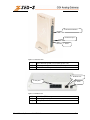
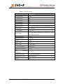
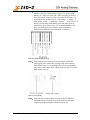
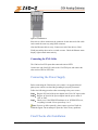
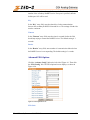
CO4 Analog Gateway User’s Manual Document 96-00510-01 June 2007 501 Valley Way Milpitas CA 95035 USA Voice: +1-408-587-9333 Fax: +1-408-586-9038 www.zed-3.com User’s Manual, document 96-00510-01 -1- Copyright and Trademarks The information contained in this document is subject to change at any time without prior notification. Specifications of the product are subject to change at any time without notice. Copyright © 2007 Zed-3; all rights are reserved. No part of this publication, including text, examples, diagrams, or icons, may be reproduced, transmitted, or translated in any form or by any means, electronic, mechanical, manual, optical or otherwise, for any purpose, without prior written permission of Zed-3. Zed-3 may have patents or pending patent applications, trademarks, copyrights, or other intellectual property rights covering subject matter in this publication. The furnishing of this document does not give you license to these patents, trademarks, copyrights, or other intellectual property. Zed-3, the Zed-3 logo, the Zed-3 mark, and CO4 are trademarks of Zed-3. All other trademarks used herein are the property of their respective owners. Copyright © 2007 Zed3; all rights are reserved. About Zed-3 Zed-3 is a premier provider of IP communications solutions for residences, businesses, enterprises, governments, and military organizations. The products are sold globally through a network of channel partners and also as OEM products to larger suppliers of communications or networking products and services. The products from Zed-3 provide innovative and reliable VoIP solutions. Each of the products has been engineered to provide a complete set of features required for a majority of applications. The products have been specifically designed to address markets where the cost of ownership is a factor in the purchasing decision. The products are sold and serviced through business partners worldwide with comprehensive service and support by Zed-3’s offices. Zed-3 is a corporation incorporated in California USA with its headquarters in Milpitas, California. Zed-3 has regional offices in Beijing (China), Bangalore (India), and Singapore. For more information on Zed-3 or its products, access http://www.zed-3.com. User’s Manual, document 96-00510-01 -2- TABLE OF CONTENTS CO4 Analog Gateway....................................................................................................................................... 1 User’s Manual................................................................................................................................................... 1 PRODUCT INTRODUCTION .......................................................................................................................... 5 Overview .................................................................................................................................................... 5 Features ...................................................................................................................................................... 5 Hardware Platform ..................................................................................................................................... 6 Physical............................................................................................................................................... 6 System Specifications......................................................................................................................... 8 PREPARATION FOR INSTALLATION.......................................................................................................... 9 Safety Check............................................................................................................................................... 9 Installation Environment ............................................................................................................................ 9 Temperature/Humidity ....................................................................................................................... 9 Dust Control and Air Flow ............................................................................................................... 10 Interference and Lightening Hazard ................................................................................................. 10 Installing the CO4............................................................................................................................. 10 Inspecting CO4 and Its Accessories ......................................................................................................... 10 INSTALLATION ............................................................................................................................................. 12 Installing the CO4..................................................................................................................................... 12 Connecting the Cables .............................................................................................................................. 12 Connecting the Ethernet Port............................................................................................................ 12 Connecting the FXO Cable............................................................................................................... 14 Connecting the Power Supply .................................................................................................................. 14 Final Checks after Installation .................................................................................................................. 14 FUNCTION DESCRIPTION ........................................................................................................................... 15 Registration............................................................................................................................................... 15 System Configurations ............................................................................................................................. 16 Software Version .............................................................................................................................. 17 Hardware Version............................................................................................................................. 17 DSP Version ..................................................................................................................................... 17 RTP Port Min ................................................................................................................................... 17 RTP Port Max................................................................................................................................... 18 First Digit Timeout ........................................................................................................................... 18 Inter Digit Timeout........................................................................................................................... 18 DTMF Mode..................................................................................................................................... 18 Default Codec ................................................................................................................................... 18 Echo cancellation.............................................................................................................................. 19 Set up the Phone Numbers........................................................................................................................ 19 Hardware .......................................................................................................................................... 19 Prefix ................................................................................................................................................ 19 SIP Setting ................................................................................................................................................ 20 SIP Port............................................................................................................................................. 20 SIP Proxy.......................................................................................................................................... 20 SIP Registrar..................................................................................................................................... 20 Registration Expires(s) ..................................................................................................................... 21 SIP Domain Name ............................................................................................................................ 21 Authentication Mode ........................................................................................................................ 21 User Name ........................................................................................................................................ 21 Password........................................................................................................................................... 21 User’s Manual, document 96-00510-01 -3- Network Configuration............................................................................................................................. 21 Hostname.......................................................................................................................................... 22 Gateway IP Address ......................................................................................................................... 22 DHCP ............................................................................................................................................... 22 Ethernet IP Address .......................................................................................................................... 23 Subnet Mask ..................................................................................................................................... 23 Hardware Address ............................................................................................................................ 23 DNS .................................................................................................................................................. 23 DNS Primary Server......................................................................................................................... 23 DNS Alternate Server....................................................................................................................... 23 PPPoE ............................................................................................................................................... 23 Time Primary Server ........................................................................................................................ 24 Time Alternate Server ...................................................................................................................... 24 Timeout............................................................................................................................................. 24 Interval.............................................................................................................................................. 24 Dialing Plan and Routing Table ............................................................................................................... 24 Setting up the Dialing Plan ............................................................................................................... 24 Set up the Routing Table .................................................................................................................. 26 Set up the FXO ......................................................................................................................................... 29 Phone Number .................................................................................................................................. 30 Registration....................................................................................................................................... 30 Display Name ................................................................................................................................... 30 Password........................................................................................................................................... 30 Originating Restriction ..................................................................................................................... 30 Hotline .............................................................................................................................................. 31 Dialtone ............................................................................................................................................ 31 Echo Cancellation............................................................................................................................. 31 Detect FSK ....................................................................................................................................... 31 Hotline Number ................................................................................................................................ 31 Advanced Options .................................................................................................................................... 31 System Advanced Options................................................................................................................ 31 Advanced FXO Options ................................................................................................................... 35 Advanced IP Options........................................................................................................................ 37 Advanced SIP Options...................................................................................................................... 39 Log Information........................................................................................................................................ 41 Call Status Information..................................................................................................................... 41 Resources Information...................................................................................................................... 42 Message Information ........................................................................................................................ 42 Error Information.............................................................................................................................. 43 Startup Information........................................................................................................................... 43 Clear Message Information............................................................................................................... 44 System Tools ............................................................................................................................................ 44 Restore Factory Setting .................................................................................................................... 44 Software Update ............................................................................................................................... 47 Change Password.............................................................................................................................. 47 Restarting the CO4 ........................................................................................................................... 48 Exit ........................................................................................................................................................... 48 User’s Manual, document 96-00510-01 -4- 1 PRODUCT INTRODUCTION Overview The CO4 Analog Gateway is an embedded device that is a standalone SIP to PSTN gateway. It converts the format of a phone call to allow it to pass between the IP network and the public telephone network. The CO4 connects to the PSTN using 4 FXO ports. It is a great complement to any SIP based IP PBX system that needs analog lines for failovers. Features The CO4 has the following features: • It supports SIP (RFC 3261). • It supports route selection (it can route a call or direct it to the internet according to the called number). • It supports RADIUS based CDR protocol. • It supports gain adjustment to FXO ports. • It supports the intrusion into NAT through a STUN server. • It supports traditional terminal devices, including phones, fax, and PBX. • It supports a variety of supplementary services such as All forward, Forward No Answer, Forward Busy Line, Call waiting, and Distinctive Ring, etc. User’s Manual, document 96-00510-01 -5- • It can obtain static IP address or capture mobile IP address through DHCP and PPPoE • It supports the traditional fax service using T.30 and T.38 formats • CO4 with FXO ports • It supports the following signaling protocols: • • SIP (Compliant to RFC 3261 and TISPAN) It supports the following codec: • • • • • • • G.711 G.723.1 G.729A GSM iLBC G.168 Echo Cancellation DTMF RFC2833 and T.38 Hardware Platform Physical User’s Manual, document 96-00510-01 -6- 3. FXO Status Indicator 2. Ethernet port 1. Power Figure 1-1 CO4 Front View ① ② ③ Power indicator (PWR). It is lit when power is on. Ethernet port indicator. It is lit when it is in operation. FXO indicators. The port number is lit when in use. 1. Ethernet Port 3. FXO ports 2. Power Figure 1-2 CO4 Rear View ① ② ③ 10/100 baseT Ethernet port Power plug-in FXO ports, a total of 4 User’s Manual, document 96-00510-01 -7- System Specifications Table 1-1 CO4 Specification Specification Internal Memory 32MB Flash Memory 4MB On-hook Battery -56V Off-hook Battery -24V Ringing Voltage 60V REN Equivalence 5 for short loop ( 1000 feet), 3 for long loop (5000 feet) Loop Current = or > 21 mA Loop Resistance Up to 188 Ω Level two surge protection. Can stand up to 1000V Surge Voltage (10/100uS) power surge Max Line Length 1500 m Off-hook Detection Loop Start Dialing DTMF Input Voltage 12V DC Input Current 1.5Amp (Max) Power Consumption 15Watt (Max) Operation Temperature 0 ~ 40°C Non Operation Temperature –25 ~ 70°C Operation Humidity 5 ~ 95% (Non Condensed) Dimension (H×L×W) 300x190x45 mm Weight 800g User’s Manual, document 96-00510-01 -8- 2 PREPARATION FOR INSTALLATION To avoid any human injury and physical damage on the device, please read this chapter carefully before the installation. Safety Check Please follow the safety guidelines when installing CO4. • Keep away from wet group and heat • Ensure safe use of electricity • Ensure to connect all the interface cables correctly Installation Environment Temperature/Humidity The CO4 installation room must maintain normal temperature and humidity. If the room temperature exceeds the specified maximum temperature, it will shorten the live of the electrical insulation material. If the room humidity exceeds the specified humidity, CO4 may experience electrical static shock and shrinkage of electric insulation material in the metal package. It may also cause metal corrosion. All these will drastically shorten the life span of the CO4. It is strongly recommended to control the environmental User’s Manual, document 96-00510-01 -9- temperature between 0 ~ 40ºC and humidity between 5% ~ 95% (none condensing). Dust Control and Air Flow Dust falls on the CO4 might cause intermittent failure in electrical connections. It may cause long term damage to the CO4, equipment failure, and shorten equipment life span. Therefore, the CO4 needs to have ample air flow in front of the CO4 air intake and outtake for proper heat exhaust. Interference and Lightening Hazard The CO4 may experience various types of EMI hazards in operation and its performance may be impacted. To reduce those hazards: • Do not install the CO4 close to high power wireless equipment, RADAR transmission site, and high frequency high electric current devices. • The CO4 comes with Level 2 lightening protection. Its operation site requires Level 1 lightening protection. • The CO4 must have its own power source and should be electrical interference free • Ensure proper grounding Installing the CO4 When installing the CO4 please make sure the CO4 is secured and has ample space for air flow. Inspecting CO4 and Its Accessories After the installation preparation is completed, the shipping package can be opened to examine all the items in the package. The list of items for the CO4 is shown in Table 2 - 1. Table 0-1 CO4 Basic Configuration and Accessories Model Number User’s Manual, document 96-00510-01 Qty Description - 10 - Model Number Qty Description CO4 1 Each CO4 has 4 FXO ports. 1 1 1 CO4 DC adaptor 12V 1.5A 5 meter Ethernet cable, 1.5m in length CO4 power cord User’s Manual, document 96-00510-01 - 11 - 3 INSTALLATION Installing the CO4 Since the CO4 is compact, you can put it to a clean and flat workspace. Make sure it is secured and has ample space for air flow. Connecting the Cables Connecting the Ethernet Port The CO4 has one 10/100 Base-T Ethernet port with a RJ45 connector. It is equipped with a LED status display. The Ethernet Cable needs to be carefully made to ensure IP data and voice quality. The following is the Ethernet cable making scheme: Step1: A user can use a proper cable peeling cutter to peel away 3cm skin of a CAT-5 cable. What is left is shown in Figure 3-1. Figure 0-1 User’s Manual, document 96-00510-01 - 12 - Step2: Twisted pairs. Currently, the most commonly used standard wiring scheme is EIA/TIA T568B shown in Figure 3-2. In the wiring scheme, pin 1 and 2 are a pair, pin 3 and 6 are a pair, pin 4 and 5 are a pair and pin 7 and 8 are a pair. According to the Figure 3-2, twisted pairs line up with colors (1: white orange,2: orange,3: white green,4:blue,5: white blue,6:green,7: white brown,8: brown). It is specially noted that the green and white green are separated by a pair of blue wires. It is a common mistake to put green and white green close together, which will result in interference and therefore lower transmission efficiency. Figure 0-2 T568B wire pairing scheme Step3: After lining up wires to the correct pin positions, trim all the twisted pairs with a cable cutter, leaving 15mm leads exposed. Then follow Figure 3-3 by inserting wires to their corresponding pin position in the plastic shell of RJ45 connector. Pin 1 will house white orange wire, etc. Figure 0-3 RJ 45 Wiring Step4: After wires have been properly inserted into RJ45 connector; a cramping tool can secure the wires to the connector and make connections to the metal pins as shown in Figure 3-4. User’s Manual, document 96-00510-01 - 13 - Figure 0-4 Finished RJ 45 Since this is a direct connection, the connector for the other end of the cable can be made the same way using RJ45 connector. After the Ethernet cable is ready, Connect one end of the cable to CO4’s WAN port and the other end to a switch or router. Check the Ethernet status display: light or flash means activity. Connecting the FXO Cable The CO4 has four FXO ports that connect the unit to PSTN. Connect one end of the RJ11 cable to the CO4 FXO port, and connect the other end to a PBX or PSTN line. Connecting the Power Supply Before connecting the CO4 into the power outlet, it is suggested that triphase power outlet be used and the grounding be properly connected. Follow the following procedure when connecting to the power source: Step1: Plug the DC head of the power adaptor into CO4’s DC input socket. Step2: Plug the AC head of the power adaptor into the power outlet of 110V or 220V. Step3: Check to see if the PWR LED indicator is on. If PWR LED is on, everything is normal. If not, repeat Steps 1 to 2. Note: If power up fails repeatedly, please contact your local VAR for technical support. Do not attempt to open the CO4 to fix any problems. Final Checks after Installation User’s Manual, document 96-00510-01 - 14 - After installing the CO4 and before it is powered on, please make sure of the following: • There is ample air space around the CO4 for heat exhaustion. • The power cord is the one that comes with the package. • Make sure the ports are connected to the right devices. 4 FUNCTION DESCRIPTION Registration Step1: Power up the CO4. The CO4 by default uses DHCP, and will automatically obtain an IP address; if the CO4 cannot get an IP address (when you connect to the computer directly), it uses default IP address “192.168.2.218”. You should statically assign an IP address to the CO4. After boot up (when customer’s line LCD stops flashing)﹐connect port one of the CO4 to a PSTN phone line and call the phone number for the phone line you just connected to the CO4. For example, if the number for that phone line is 1-408587-9333, call that number. Step2: Once the call is established, you will hear a continuous ring tone. Press the # key twice to listen to the IP address. Step3: Double click to open IE Explorer in the computer which is connected to the same network as CO4. Step4: Type in CO4 IP address(for example:192.168.2.218) ,and the web interface will display as shown in Figure 4-1. User’s Manual, document 96-00510-01 - 15 - Figure 0-1 CO4 Analog Gateway Configurations Interface CO4 has two levels of management:the administrator level (default password:“0000”) and the operator level (default password:“operator”). Administrator level has higher access privilege, and is allowed to change password for all users at all levels. Operator level has lower access privilege, and certain options are not available including network configurations, password management and factory default reset. The CO4 allows multiple users to log on at the same time. Only the first user logged on with highest privilege can change configurations. The rest can only monitor configurations. (See 4.12.2 for more details ). Note1:After a user logs on, he/she will be automatically logged off if there is no activities for 10 minutes.. Note2:After completing the configuration, a user must completely log out instead of just closing the browser. This will elevate the access level of the next logged on user so he/she will be able to change the configurations. System Configurations User’s Manual, document 96-00510-01 - 16 - Click the “System Configuration” link on the left of Figure 4-1, and you will see what is shown in Figure 4-2. Figure 0-2 System Configuration Interface Software Version The Software Version field displays CO4 software version. Software automatically updates this field whenever a new software version is loaded. You can not change this field. Hardware Version The Hardware Version field displays the CO4’s hardware version. Software automatically reads hardware version and fills this field. You can not change this field. DSP Version The DSP Version field displays the CO4’s DSP software version. Software automatically updates this field whenever new software version is loaded. You can not change this field. RTP Port Min User’s Manual, document 96-00510-01 - 17 - In the “RTP Port Min” entry field, enter the minimum value of the sending and receiving RTP port. RTP Port Max In the “RTP Port Max” entry field, enter the maximum value of the sending and receiving RTP port. Each SIP call uses two RTP ports: one for RTP and the other for RTCP. So it is highly recommended you set RTP to at least eight ports. Default is 10010 ~ 10030. You do not need to change it. First Digit Timeout In the “First Digit Timeout” entry field, enter the time (in second) allowed for the dialing of the first digit. When a line goes off-hook, if within the time specified here the first digit has not been dialled, the CO4 will treat this as an abandoned call and will indicate to the caller to place the phone on hook. The default value is 12 seconds. Inter Digit Timeout In the “Inter Digit Timeout” entry field, enter the time (in second) allowed between the dialing of each digit. Counting from the last digit dialled, if no digit has been dialed within the time specified, the system will send the dialled digits out. The default value is 12 second. DTMF Mode In the “DTMF Mode” entry field, select the transmission mode. This parameter is used to set the DTMF signal transmission mode. Options are Audio mode, 2833 mode, and INFO mode. The default setting is Audio mode. Audio mode is a transparent transmission mode; INFO mode is information transmit mode; 2833 mode is a RTP data packet transmission mode. Default Codec In the “Default codec” entry field, enter the codices you want the CO4 to support. The CO4 supports G729A/20, G723/30, PCMU/20, PCMA/20, GSM, iLBC. User’s Manual, document 96-00510-01 - 18 - Table 0-1 Codes supported by M8 Codec supported by CO4 G729A/20 G.729A Time interval of RTP packets transmission(unit: ms) 20 G723/30 G.723 30 PCMU/20 G.711 20 PCMA/20 G.711 20 iLBC/30 iLBC 30 GSM/20 GSM 20 Codec mode Echo cancellation In the Echo cancellation select on to enable echo cancellation and off to disable echo cancellation. Set up the Phone Numbers Click the “Phone Number” link on the left of Figure 4-1, and you will see what is shown in Figure 4-3: Figure 0-3 Phone Number setting screen Hardware Leave the Hardware Settings field as it is. This parameter is already predefined by the Zed-3. You do not need to change it. Prefix User’s Manual, document 96-00510-01 - 19 - In the “Prefix” entry field, enter the value of the prefix of the serial phone numbers assigned to the gateway. For example, if the phone numbers of the gateway are 2002007 to 2002010, then 200 should be entered in the Prefix field. SIP Setting Click the “SIP” link on the left of Figure 4-1,and the SIP Settings screen displays. Figure 0-4 SIP settings screen SIP Port In the “SIP Port” entry field, enter the number of SIP local port. The default value is 5060. Local port number could be set at will, as long as it doesn’t conflict with the other port numbers in the system. SIP Proxy In the “SIP Proxy” field, enter the address and port number of the SIP proxy. The address and port number are separated by a colon. The address can be either an IP address or an FQDN (Fully Qualified Domain Name). When using the FQDN, it is necessary to enable the DNS service in the “Network Setting” page and set the parameter of DNS server. SIP Registrar User’s Manual, document 96-00510-01 - 20 - In the “SIP Registrar” entry field, enter the address and port number of the SIP Registrar. The address and port number are separated by a colon. The address can be either an IP address or a FQDN. Registration Expires(s) In the “Registration Expires(s)” entry field, enter the valid time (in second) for SIP re-registration. The default value is 30 seconds. SIP Domain Name In the “SIP Domain Name” entry field, enter the SIP domain name. If the field is left empty, the CO4 will use the address of the SIP proxy as the domain name. Authentication Mode In the “Authentication Mode” field, use the drop down menu to make a selection. “Per Endpoint” means to register and authenticate according to each individual line; “Per Gateway Reg” means to register and authenticate according to the gateway; “Per Gateway Auth” means to register according to each individual line, and to authenticate according to the gateway. User Name Set the “User Name” entry field if you have selected “Per Gateway Reg” or “Per Gateway Auth” for the “Authentication Mode”; Password In the “Password” entry field, enter authentication password, which can be digits or characters. The password is case sensitive. If you have selected “Per Gateway Reg” or “Per Gateway Auth” for the “Authentication Mode,” you need to set this parameter. Network Configuration User’s Manual, document 96-00510-01 - 21 - Click the “Network Config” link on the left side of Figure 4-1. The Network Settings screen displays: Figure 0-4 Network Settings Screen Hostname In the “Hostname” entry field, enter the name for this CO4. You can use your own naming convention according to your network setup. Gateway IP Address In the “Gateway IP Address” entry field, enter the IP address of the default gateway if the CO4 does not have DHCP enabled. DHCP In the “DHCP” entry field, select “on” or “off” to indicate whether to use DHCP to obtain the IP address for the CO4. User’s Manual, document 96-00510-01 - 22 - Ethernet IP Address In the “Ethernet IP Address” entry field, enter the IP address for the CO4. If the CO4 is using DHCP to obtain its IP address, do not modify this field. Subnet Mask In the “Subnet Mask” entry field, enter the network address for the CO4. This field should not be modified if the CO4 has DHCP enabled. Hardware Address Leave the Hardware Address as it is. You are not allowed to change it. DNS In the DNS entry field, select “on” or “off” to enable or disable the DNS service. You need to turn on the DNS service when the CO4 uses a domain name as the proxy server address or registration server address. DNS Primary Server In the “DNS Primary Server” entry field, enter the CO4’s primary DNS server address if you have turned on the DNS service. DNS Alternate Server In the “DNS Alternate Server” entry field, enter the alternate DNS server address. PPPoE In the PPPoE field select “on” or “off” to indicate to enable or disable the PPPoE service. • If you have enabled PPPoE, you need to enter the user name in the “PPPoE Username” entry field. User’s Manual, document 96-00510-01 - 23 - • If you have enabled PPPoE, you need to enter the password in the “PPPoE Password” entry field. Time Primary Server In the “Time Primary Server” entry field, enter the IP address of the primary Time server. Time Alternate Server In the “Time Alternate Server” entry field, enter the IP address of the alternate Time server. Timeout In the “Timeout” entry field, enter the time (in minute) allowed to locate the Time server. If the server is not located within the time allowed, the CO4 will try to locate it again. Interval In the “Interval” entry field, enter the time interval (in minute) at which the CO4 will synchronize its time with the Time server. Dialing Plan and Routing Table Setting up the Dialing Plan Click the “Dialing Plan” link on the left side of Figure 4-1. Then click the “Digit Map” link. The Digit Map Rules screen displays, as shown in Figure 4-15: User’s Manual, document 96-00510-01 - 24 - Figure 0-5 Digit Map Rules Screen The CO4 has in its default digit map most of the domestic digit map rules. You do not have to re-configure them. You can add new rules when necessary. The following is an illustration of the common rules: Table 0-2 Common Digit Map Rules X . ## x.T x.# *xx #xx [2-8]xxxxxx 02xxxxxxxxx 013xxxxxxxxx 13xxxxxxxxx 11x Any single digit between numbers 0 to 9. any multiple digit between numbers 0 to 9. terminate dialing after receiving two digits. ## is CO4 gateway’s default function key for listening to the IP address. The gateway will check a number of any lengths that is composed of any number between 0 and 9. If no new digits are received within the “dialing finish” time, the gateway will send out the detected number. a number of any length that starts with any number between 0 and 9. If the end user dials # right after the number, CO4 will stop number reception and send out the number before #. terminate dialing after receiving * plus any two digits. *xx is mainly used to enable the supplementary services (such as Distinctive Ring, Do Not Disturb, and Call Forwarding). end dialing after receiving # plus any two digits. #xx is mainly used to disable the supplementary services. a seven-digit number that starts with any number between 2 and 8. This is used to terminate local call dialing. an 11-digit number that starts with 02. This is used to terminate long distance call dialing that starts with 02. a 12-digit number that starts with 013. This is used to terminate long distance cellular calls that start with 013. an 11-digit number that starts with 13. This is used to terminate local cellular calls that start with 13. a three-digit number that starts with 11. This is used to terminate emergency calls. User’s Manual, document 96-00510-01 - 25 - a five-digit number that starts with 9. This is used to terminate special service calls send out the number right after receiving 17911. This serves as an example of terminating a special number. 9xxxx 17911 Set up the Routing Table Click the Dialing Plan link on the left side of Figure 4-1. Then click Route Table. The Route Table screen displays, as shown in Figure 4-16: Figure 0-6 Routing Table Screen Routing table serves two main functions: number swapping and route exchange. The table is executed from top to bottom. Number swapping always has advantage over route exchange. A routing table can have a maximum of 50 entries. Note: The routing table is empty by default. All the calls go to the SIP Proxy server, 1. Number Swapping A number swap entry consists of three sections: Origination, Number, and Action. • Origination can be one of the following values: IP and FXO. IP can be any IP address: A specific IP address without a port number or a specific IP address with the port number. FXO can be a specific line number or a group of FXO lines. (For example FXO1, FXO2 or FXO 1 – 2, etc.) • Number can be the calling number, or the called number. Default is the called number. If it is the calling number, add CPN before the number as the identifier. The number consists of any digit User’s Manual, document 96-00510-01 - 26 - between 1 to 9, *, ., #, X etc, just like the digit map. The common rules are: • Numbers, such as 114, 61202700. The beginning digits of a number, such as 61xxxx, or 612x, or 61. Expressions such as 268[0-1, 3-9], which indicates a number that starts with 268 and followed by any number from 0 to 1 or 3 to 9. The search for a matching number follows the principle of “shortest and quickest”. For example, x equals all numbers; xx equals all two-digit numbers; 12x equals all three-digit numbers that start with 12. Action defines the processing method and the actual information that has been processed. It can be one of the following three values: KEEP: Keep means to keep the number. Another number goes after it. If that number is positive, it means to count the number from the left; if the number is negative, it means to count the number from the right. For example, IP 02161202700 KEEP -8. This means to keep the last eight digits of this called number from the IP, that is 61202700. REMOVE: Remove means to remove the number. Another number goes after it. If that number is positive, it means to count the number from the right; if the number is negative, it means to count the number from the left. For example, IP 021 REMOVE 3. This means to remove 021 if the called number from an IP starts with 021 ADD: Add means to add digits before or after the called number. Another number goes after it. If that number is positive, it means to add before the number; if the number is negative, it means to add after the number. For example, IP CPNX ADD 021 This means to add 021 to all the CNP from IP. REPLACE: means to replace the number, followed by the number to be replaced to. For example, “IP CPN88 User’s Manual, document 96-00510-01 - 27 - REPLACE 2682000,” means for a CPN from the IP trunk that starts with 88, replace it with 2682000 END: means to terminate certain number processing. When performing number swapping from top to bottom, if END or ROUTE is present, then end number swapping. For example, IP IP IP 12345 ADD -8001 12345 REMOVE 4 12345 END This means for the called number from an IP trunk that starts with 12345, first add 8001 to the right of the number; then remove the first four digits; and end the number swapping for CDN that starts with 12345.Another example, IP[222.34.55.1] IP[222.34.55.1] CPNX. REPLACE 2680000 CPNX. ROUTE FXO 2 This means for any CPN of any lengths that comes from IP address 222.34.55.1, replace it with 2680000, and then route it to the second PSTN line. 2. Route Exchange One routing entry consists of five sections: Origination, Number, Action, Destination, and Destination Information. Routing table routes the number from an origination to the destination. • Origination can have the following values: IP and FXO. IP can be any IP address, a specific IP address, or specific IP address with the port number. FXO can be a specific line number or a group of FXO lines. (For example FXO2 or FXO 1 – 2, etc.) • Number can be the calling number, or the called number. Default is the called number. If it is the calling number, add “CPN” before the number as the identifier. The number can use any digit between 1 to 9, *, ., #, X etc, just like the digit map. The common rules are: Numbers, such as 114, 61202700 The beginning digits of a number, such as 61xxxx, or 612x, or 61 Expressions such as 268[0-1, 3-9], which indicates a number that starts with 268 and followed by any number from 0 to 1 or 3 to 9 The search for a matching number follows the principle of “shortest and quickest”. For example, x equals all numbers; User’s Manual, document 96-00510-01 - 28 - xx equals all two-digit numbers; 12x equals all three-digit numbers that start with 12 • Action should only be ROUTE, meaning to route a call. • Destination can have the following values: NONE, IP, and FXO. Routes that have IP as the Origination usually have FXO, or NONE as Destination Routes that have FXO as the Origination usually have IP or NONE as Destination Routes that have IP as Destination: the Destination Information section must provide a specific gateway IP address and its port number for SIP (if no port number is defined, the CO4 uses the default port number 5060). For example: 192.168.2.10:5066 IP CPN[1, 3-5] ROUTE NONE This means a call from an IP address with calling number that start with 1, 3, 4, and 5 will not be routed. Set up the FXO The CO4 has FXO lines. Each line is configured the same way. You can customize the configuration. The following is a sample configuration. Click the “FXO Config” link on the left side of Figure 4-1. Then click the “FXO 1” link. The FXO Settings screen displays, as shown in Figure 4-18: User’s Manual, document 96-00510-01 - 29 - Figure 0-7 FXO Setting Screen Phone Number In the “Phone Number” entry field, enter the phone number that is set up in section 4.3. Registration In the “Registration” drop-down menu, select “on” (to register) or “off” (not to register). Display Name In the “Display Name” entry field, enter the content to display in the outgoing calls. You can enter up the 30 characters. FXO lines that have name display capability to display what is entered here. Password In the “Password” entry field, enter the registration password if you selected “on” in Step 3. Originating Restriction User’s Manual, document 96-00510-01 - 30 - In the “Originating Restriction” drop-down menu, select “on” (to indicate the line can only receive calls but not initiate calls) or “off” (no restriction). Hotline In the “Hotline”drop-down menu, select “on” (enable) or “off” (disable). Dialtone In the “Dialtone” drop-down menu, select “on” (enable) or “off” (disable). This function is disabled once the Hotline function is on. Echo Cancellation In the “Echo Cancellation” drop-down menu, select “on” (enable) or “off” (disable). Detect FSK In the “Detect FSK” drop-down menu, select “on” (enable) or “off” (disable). This indicates to check and forward the calling number from PSTN or not. Hotline Number In the “Hotline Number” entry field, the Hotline number set up will display. You can also enter a different number here to overwrite the previous number. Advanced Options System Advanced Options Click the “Advance Config” link on the left side of Figure 4-1. Then click the “System Config” link. The System Optional screen displays, as shown in Figure 4-19: User’s Manual, document 96-00510-01 - 31 - Figure 0-8 System Optional Screen Event Log Type In the “Event Log Type” entry field, enter “File”. Event log, created in the format of file, is convenient for the user to store and reference. Event Log Level In Event Log Level field enter any number from 1 to 5. The higher the level, the more detailed the log. In normal situation the level is set to 3. Higher level may slow down system performance. Country ID In the “Country ID” entry field, select the country in which the gateway is operated,and gateway will adopt different disposals according to different countries' standards. Forwarding Number Mode In the “Forwarding Number Mode” entry field, use the pull down menu to select “Calling Party Number” or “Forwarding Number.” This determines if User’s Manual, document 96-00510-01 - 32 - the calling party number or the forwarding number should be displayed in the last line. For example, if the PSTN line 3221680 has call forwarding function and the forwarded number is 7558888, when line 5552525 calls 3221680, line 7558888 will display 5552525 if Calling Party Number is selected here; if Forwarding Number is selected, then line 7558888 will display 3221680. Fashion Ring Max In the “Fashion Ring Max” entry field, enter the maximum Fashion Ring file size and the highest Fashion Ring ID number. SNMP Port In the “SNMP Port” entry field, enter the UDP port used by Simple Network Management Protocol. SNMP provides a way to collect network management information from network equipments as well as a way for the equipments to report problems and errors to the network. SNMP Trap Port In the “SNMP Trap Port” entry field, enter the UDP port used by SNMP Trap command. The default value is 162. TRAP is one command of SNMP, whose main function is to send alarm asynchronously to network management workstation, notifying it that some event that fulfills the proposition has occurred. NAT IP Address In the “NAT IP Address” field, enter the static NAT IP port address in the public network. If empty, SIP local port address will be used. Normally CO4 will try to reach NAT using STUN. If STUN requests cannot be successfully carried out or STUN is not configured, CO4 will use the value here. NAT Refresh Time In the “NAT Refresh Time” entry field, enter the time interval in seconds to refresh the NAT status. This request is sent to the STUN Server. This value is used when “NAT Alive” is enabled or when the CO4 is requesting STUN services. NAT Keep Alive Select “yes” (to keep it alive) or “no” (not to keep it alive). User’s Manual, document 96-00510-01 - 33 - STUN Select “on” to turn on STUN service or “off” to turn off STUN service. STUN Server In “STUN Server” entry field, enter the IP address of the STUN server. A STUN server can send requests as well as generate responses. The STUN server normally runs in public network and therefore is stateless. If this field is empty, the default STUN server will be used. RADIUS Client Select “on” (to enable) or “off” (to disable) to turn on or off the RADIUS client feature. RADIUS Server Select “on” (to enable) or “off” (to disable) to turn on or off the RADIUS server feature. RADIUS Start Select “on” or “off” to indicate whether or not to transmit the initial RADIUS record when the RADIUS client or server feature is enabled. RADIUS Unsuccess Stop Select “on” or “off” to indicate whether or not to transmit RADIUS record of the unsuccessful calls when the RADIUS client or server feautre is enabled. Primary Server In the “Primary Server” entry field, enter the IP address and the port number of the primary RADIUS server. If no port is specified, the default port 1813 would be used. Key In the “Key” entry field, enter the shared key for the communication between the primary RADIUS client and server. The settings of both sides must be consistent. Secondary Server User’s Manual, document 96-00510-01 - 34 - In the “Secondary Server” entry field, enter the IP address and the port number of the secondary RADIUS server. If no port is specified, then the default port 1813 will be used. Key In the “Key” entry field, enter the shared key for the communication between the secondary RADIUS client and server. The settings of both sides must be consistent. Timeout In the “Timeout” entry field, enter the time (in seconds) before the CO4 should stop trying to contact the RADIUS server. The default setting is 3 seconds. Retries In the “Retries” entry field, enter number of re-transmission allowed when the RADIUS server is not responding. The default setting is 3 seconds. Advanced FXO Options Click the “Advance Config” link on the left side of Figure 4-1. Then click the “FXO Config” link. The FXO Optional screen displays, as shown in Figure 4-20: Figure 0-9 FXO Optional Screen FXO Gain User’s Manual, document 96-00510-01 - 35 - In the “FXO Gain” entry field, enter the volume increase for the PSTN line. The default is -3.5dB. FXO Relay Time In the “FXO Relay Time” entry field, enter the delayed time (in milliseconds) before sending out the digits to the PSTN from the FXO side. The default is 400ms. Digit On Time In the “Digit On Time” entry field, enter any number from 80 to 150. This is the duration for each digit. The default is 100ms. Digit Off Time In the “Digit Off Time” entry field, enter any number from 80 to 150. This is the interval at which FXO sends out digits. The default is 100ms. Busy Tone Repetition In the “Busy Tone Repetition” entry field, enter a number from 2 to 5. This is the number of times the CO4 keeps checking busy tone before it takes further action. Busy Tone Parameter 1 In the “Busy Tone Parameter 1” entry field, enter one of the signal frequency parameters (IS is 61485). The formula is: frequency=[65536*cos(2*PI*f/8000)] where the value of frequency is an integer and f is the actual frequency value. Busy Tone Parameter 2 In the “Busy Tone Parameter 2” entry field, enter another signal frequency parameter (IS is 0). The formula is: frequency=[65536*cos(2*PI*f/8000)] where the value of frequency is an integer and f is the actually frequency value. Busy Tone On Time In the “Busy Tone On Time” entry field, enter the time (in milliseconds) each busy tone will last. This time should be determined by the equipment the FXO is connected to. International standard is 350ms. Busy Tone Off Time User’s Manual, document 96-00510-01 - 36 - In the “Busy Tone Off Time” entry field, enter the time interval between each busy tone. This time should be determined based on the equipment the FXO is connected to. International standard is 350ms. Advanced IP Options Click the “Advance Config” link on the left side of Figure 4-1. Then click the “IP Config” link. The IP Optional screen displays: Figure 0-10 IP Optional screen RTP Jitter Param 1 User’s Manual, document 96-00510-01 - 37 - Leave the RTP Jitter Param1 (frame number,De-Jitter Buffer Maximum) to its default setting of 50. It is recommended that you do not change this value. RTP Jitter Param 2 Leave the De-Jitter Buffer Minimum (frame number,De-Jitter Buffer Minimum) to its default setting of 3. It is recommended that you do not change this value. 2833 Packet Type In the “2833 Packet Type” entry field, enter a value from 97 to 127. This parameter is used for transmitting 2833 packet type. The default load type is 97. Sending Busy Tone for Network Breakdown Select “on” or “off” to configure the CO4 whether to send busy tones when IP network does not connect. Switch to FXO for Network Breakdown Select “on” or “off” to configure the CO4 whether to switch all calls to the FXO ports when the IP network doesn’t connect. It is recommended that you set this parameter to “on”. If the IP network doesn’t connect, in order to protect the router, all IP calls go to the PSTN through the FXO ports. VAD In the “VAD Activate:” drop-down menu, if you select yes, the speech packet will not be sent out during mute, and noise is added to the speech stream to replace the mute. G.723.1 Rate In the “G.723.1 Rate (BPS)” entry field, enter either 5300 or 6300 according to specific applications. IP Packet in Tos The “IP Packet in Tos” field is used to set the quality assurance for the different classes of service. T.38 User’s Manual, document 96-00510-01 - 38 - In the “T.38” drop-down menu, select “on” or “off” to indicate whether to use T.38 for fax over the IP. T.38 Packet Time (ms) In the “T.38 Packet Time(ms)” drop-down menu, set the packing interval for each T.38 data frame. The value can be set as the following: 10/20/30/40/50/60. T.38 Redundancy Frame Numbers In the “T.38 Redundancy Frame Numbers” drop-down menu, set the number of the T.38 data frame in each T.38 data packet (the effective range is 1 to 6). T.38 Change Port In the “T.38 Change Port” drop-down menu, select “yes” or “no” to indicate if the gateway will change the UDP port when it switches to T.38 mode. If it is set to “no,” it will use the RTP port established during the connection. Advanced SIP Options Click the “Advance Config” link on the left side of Figure 4-1. Then click the “SIP Config”. The SIP Optional screen displays: Figure 0-11 SIP Optional screen Response Using Received Port User’s Manual, document 96-00510-01 - 39 - In the “Response Using Received Port” drop-down menu, use “yes” or “no” to indicate whether to use the received port as the response port. Response Using Proxy Port In the “Response Using Proxy Port” drop-down menu, use “yes” or “no” to indicate whether to use the proxy port as the response port. If “no” is selected, port 5060 is used. RTP Port Mapping In the “RTP Port Mapping” drop-down menu, use “yes” or “no” to indicate whether to use the RTP port mapping function, and use local SIP port and RTP port; when “no” is selected, the CO4 will use the port requested by STUN. Always Send 180 In the “Always Send 180” drop-down menu, select “yes” or “no.” If “yes” is selected, the CO4 will send 180 in the ISDN mode with voice prompt so that user can hear the normal ring back tone instead of voice prompt tone. CPN From Request Line In the “CPN From Request Line” drop-down menu, select “yes” to get the called number from Request Line, and “no” to get the called number from To field. Response Do Not Check Via In the “Response Do Not Check Via” drop-down menu, select “yes” to ignore the Via field of the received SIP message, and “no” to ignore the Via field of the received message. SIP TO Using Domain Name The “SIP TO Using Domain Name” field is applicable only to gateways which use character type domain name. Select “yes” to use the FQDN information (for example:[email protected]) to register, and “no” to just use the domain name (for example:[email protected]) to register. SIP VIA using NAT Information The “SIP VIA using NAT Information” field is used to specify whether to use the public network address information obtained by NAT or the private network address information when setting up the SIP VIA field. Select User’s Manual, document 96-00510-01 - 40 - “yes” to use the public network address information obtained by NAT, and “no” to use the private network address information. SIP TO Adopt Domain Name Information The “SIP TO Adopt Domain Name Information” field is used to indicate whether to use the Proxy information or the domain name information in SIP Setting when setting up SIP TO field. Yes means the gateway will use domain name information inSIP Setting; No means to use the Proxy information. SIP PRACK The “SIP PRACK” parameter is used to specify whether use reliable provision messages for SIP. Log Information Call Status Information Click the “Log Information” link on the left of Figure 4-1. Then click Call Info. The Call Info page displays: Figure 4-12 Call Log Info screen status ts d c call remote off/on-hook and ringing status. timeslot. DSP. This field shows the DSP chip used. channel. This field indicates the channel of DSP. identify one call number,which is a random number. remote IP address followed by RTP port number. User’s Manual, document 96-00510-01 - 41 - the local RTP port number. encoding and decoding. CO4 support the following codec: G729A/20,iLBC/30,G723/30,GSM/20,PCMU/20,PCMA/20 call state, which indicates the current state. It can be SEND; state DELIVERED; PRESENT; RECEIVED, and ACTIVE. number phone number. (C):calling number;(D):called number. timestamp which has two types:one is setup time,whose duration is 0;another is connection time. In the information shown on screen, the former is setup time, while the latter is connection time, the unit is in seconds. this is a length of digit used to identify a call when SIP is caller id switching information; the length and value of the digit are randomly generated. local codec Resources Information Click the “Log Info” link on the left of Figure 4-1. Then click “Resource Info.” The Resource Info page displays. In this page, you can see the logon information (including the IP address and level of the logon user) of all WEB users, SIP registration information, telephone information and RTP information. Figure 0-13 Resource Info screen Message Information Click the “Log Info” link on the left of Figure 4-1. The click “Message Log.” The Log Info page displays. You can check all the call related information in this page. User’s Manual, document 96-00510-01 - 42 - Figure 0-14 Log Info screen Error Information Click the “Log Info” link on the left of Figure 4-1. Then click “Error Log.” The Log Info page displays. You can check all the errors, logons, exits and overtime web access information in this page. Figure 0-15 Error Info screen Startup Information User’s Manual, document 96-00510-01 - 43 - Click the “Log Info” link on the left of Figure 4-1. Then click “Startup Info.” The Log Info page displays. You can check all the startup information of the CO4 from this page. Figure 0-16 Startup Info screen Clear Message Information Click the “Log Info” link on the left of Figure 4-1. Then click “Clear Msg Log.” You can clear the information in the “Message Information” window. System Tools Restore Factory Setting Click the “System Tools” link on the left of Figure 4-1. Then click “Restore Factory Setting.” The following displays: Figure 0-17 Restore Factory setting screen Once you press the Confirm button, the gateway will restore to the default factory settings. User’s Manual, document 96-00510-01 - 44 - The CO4 has been set with default value for general applications so under general application you do not need to set anything. The following are the default settings of CO4 gateway. They are provided for your reference. Default System Parameter Settings RTP Port Min:10010 RTP Port Max:10030 1st Digit Timeout (Second) :12 Inter Digit Timeout (Second) :12 Critical Digit Timeout (Second) :5 DTMF Transmit Mode:AUDIO Default Codec:PCMU/20, G729A/20, iLBC/30, G723/30, GSM/20, PCMA/20 Echo Cancellation:on Default SIP Settings SIP Port:5060 Registration Expires (Second) :30 Authentication Mode:Per Endpoint Default Network Parameter Settings Gateway IP Address:192.168.2.1 DHCP:on Local IP Address:192.168.2.218 Subnet Mask:255.255.255.0 DNS:off PPPoE:off Preference TIME Server:192.43.244.18 Alternate TIME Server:198.60.22.240 Timeout (Minute) :10 Query Interval (Minute) :120 Default FXO Settings Forbid to Call:off Hotline:off Dial Ton:on Echo Cancellation:on Detect FSK:off System Advanced Default Settings Event Log Type:FILE Event Log Level:3 User’s Manual, document 96-00510-01 - 45 - Country ID:China Forwarding Number Mode:Forwarding Number Fashion Ring Max:20 SNMP Port:2700 SNMP Trap Port:162 NAT Keep Alive:no STUN:off RADIUS Client Side:off RADIUS Server Side:off RADIUS Start:off RADIUS Unsuccess Stop:off Timeout (Second) :3 Retries:3 FXO Advanced Default Settings FXO Gain:-3.5 FXO Relay Time (ms) :400 Digit on Time (ms) :100 Digit off Time (ms) :100 Buy Tone Repetition:2 Busy Tone Parameter1:61485 Busy Tone Parameter2:0 Busy Tone on Time (ms) :350 Busy Tone off Time (ms) :350 Default IP Advanced Settings RTP Jitter Max (Frame) :50 RTP Jitter Min (Frame) :3 2833 Packet Type:97 Send Busy Tone for Network Breakdown:off Switch to FXO for Network Breakdown:on Generation of the Mute Compress and Comfort Noise:yes G.723.1 Rate (BPS) :5300 IP Packet in Tos Field:0x0C T.38:on T.38 Data Frame Length (ms) :40 T.38 Redundancy Fram Number:4 T.38 Change UDP Port:no T.38 Error Detect Mode:off SIP Advanced Default Settings Response Default Port Using Received Port:no Response Default Port Using Proxy Port:no User’s Manual, document 96-00510-01 - 46 - RTP Port Mapping:no Replace 18x with 180:no CPN from Request Line:no Response Do Not Check Via:yes Use the Full Domain Name Information during Registering:yes Keep the Original Contact Information:no SIP VIA using NAT Information:yes SIP TO adopt Domain Name Information:yes Software Update Click the “System Tools” link on the left of Figure 4-1. Then click “Software Update.” The following displays: Figure 0-18 Software Update screen FTP Server Enter the IP address or domain name of the FTP server which is used to update the software. Filename This parameter specifies the name of the file which the CO4 would download and use for upgrade. Change Password Click the “System Tools” link on the left of Figure 4-1. Then click “Change Password.” The following displays: User’s Manual, document 96-00510-01 - 47 - Figure 0-19 Change Password screen Only an administrator has the authority to changes password. The first three fields are used to change administrator password. Input the old password in the “Old password” entry field, and input the new password in the “New password” entry field. Enter the new password again in the “Confirm new password” entry field; click the “Submit” button to finish. The current operator password is displayed in plain text mode. An administrator can change it at any time and does not need to input the current administrator password when he/she wants to change the operator password. Enter a new password in the “Operator Password” entry field, and click the “Submit” button to finish. Restarting the CO4 Click the “System Tools” link on the left of Figure 4-1. Click “Reboot.” After that, press the “Reboot” button to restart the gateway. Figure 0-20 Restart Gateway screen Exit Click the “Logout” link on the left of Figure 4-1. User’s Manual, document 96-00510-01 - 48 -