1
2354235 11/2008
Altivar 61/71
EtherNet/IP™ card
User manual
VW3A3320
HRB10065
02/2013
www.schneider-electric.com
efesotomasyon.com
The information provided in this documentation contains general descriptions and/or technical characteristics
of the performance of the products contained herein. This documentation is not intended as a substitute for
and is not to be used for determining suitability or reliability of these products for specific user applications. It
is the duty of any such user or integrator to perform the appropriate and complete risk analysis, evaluation and
testing of the products with respect to the relevant specific application or use thereof. Neither Schneider
Electric nor any of its affiliates or subsidiaries shall be responsible or liable for misuse of the information
contained herein. If you have any suggestions for improvements or amendments or have found errors in this
publication, please notify us.
No part of this document may be reproduced in any form or by any means, electronic or mechanical, including
photocopying, without express written permission of Schneider Electric.
All pertinent state, regional, and local safety regulations must be observed when installing and using this
product. For reasons of safety and to help ensure compliance with documented system data, only the
manufacturer should perform repairs to components.
When devices are used for applications with technical safety requirements, the relevant instructions must be
followed.
Failure to use Schneider Electric software or approved software with our hardware products may result in
injury, harm, or improper operating results.
Failure to observe this information can result in injury or equipment damage.
© 2012 Schneider Electric. All rights reserved.
efesotomasyon.com
7DEOHRIFRQWHQWV
Table of contents ____________________________________________________________________________________________ 3
Important Information _________________________________________________________________________________________ 4
About the book ______________________________________________________________________________________________ 5
Before you begin_____________________________________________________________________________________________ 6
Documentation structure_______________________________________________________________________________________ 7
Introduction _________________________________________________________________________________________________ 8
Presentation _____________________________________________________________________________________________ 8
Notation ________________________________________________________________________________________________ 8
Hardware setup _____________________________________________________________________________________________ 9
Receipt _________________________________________________________________________________________________ 9
Hardware description ______________________________________________________________________________________ 9
Installing the card in the drive. See the Installation Manual (1760643 or 1760655). _____________________________________ 10
Connecting to the EtherNet/IP network __________________________________________________________________________ 11
Card RJ45 connector pinout ________________________________________________________________________________ 11
Example of connection to an EtherNet/IP network _______________________________________________________________ 11
Ethernet menu _____________________________________________________________________________________________
Access to EtherNet menu via graphic display terminal____________________________________________________________
Access to EtherNet menu via the integrated display terminal ______________________________________________________
Ethernet/IP configuration with the HMI ________________________________________________________________________
Detail of the configured parameters __________________________________________________________________________
Assemblies and scanner configuration ________________________________________________________________________
13
13
13
14
16
16
Configuration of the assemblies ________________________________________________________________________________
Configuration of the assemblies: overview _____________________________________________________________________
Configuration of the assembly (100,101) Schneider-Electric native profile ____________________________________________
Configuration of the assembly (103,104) Allen Bradley® profile ____________________________________________________
Configuring the communication scanner ______________________________________________________________________
Configuring the control ____________________________________________________________________________________
17
17
18
19
20
21
Fault management __________________________________________________________________________________________ 26
Fault management _______________________________________________________________________________________ 26
Status of the LEDs _______________________________________________________________________________________ 27
Configuration of monitored parameters __________________________________________________________________________ 28
Standard Web server ________________________________________________________________________________________
Webserver function_______________________________________________________________________________________
Applets ________________________________________________________________________________________________
Access to the Web server__________________________________________________________________________________
Web server user interface__________________________________________________________________________________
“Home” menu ___________________________________________________________________________________________
"Monitoring" menu _______________________________________________________________________________________
Diagnostics _____________________________________________________________________________________________
“Setup” menu ___________________________________________________________________________________________
“Security” Submenu ______________________________________________________________________________________
“Documentation” menu ____________________________________________________________________________________
29
29
30
31
32
32
32
36
39
45
46
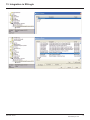
Integration in RSLogix _______________________________________________________________________________________
Principle _______________________________________________________________________________________________
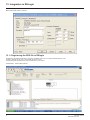
Procedure _____________________________________________________________________________________________
Registering the EDS file in RSlogix __________________________________________________________________________
47
47
47
54
CIP objects ________________________________________________________________________________________________
Supported object classes __________________________________________________________________________________
Identity object ___________________________________________________________________________________________
Message router object ____________________________________________________________________________________
Ethernet Link object ______________________________________________________________________________________
TCP/IP Interface object____________________________________________________________________________________
Connection object manager________________________________________________________________________________
Motor data object ________________________________________________________________________________________
Control supervisor object __________________________________________________________________________________
AC/DC Drive Object ______________________________________________________________________________________
Assembly object _________________________________________________________________________________________
Application objects _______________________________________________________________________________________
57
57
57
61
63
66
68
69
70
72
73
74
Explicit Messaging __________________________________________________________________________________________ 76
Device profiles _____________________________________________________________________________________________ 77
HRB10065 02/2013
3
efesotomasyon.com
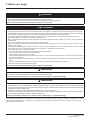
,PSRUWDQW,QIRUPDWLRQ
127,&(
Read these instructions carefully, and look at the equipment to become familiar with the device before trying to install, operate, or
maintain it. The following special messages may appear throughout this documentation or on the equipment to warn of potential
hazards or to call attention to information that clarifies or simplifies a procedure.
The addition of this symbol to a Danger or Warning safety label indicates that an electrical hazard exists, which will result
in personal injury if the instructions are not followed.
This is the safety alert symbol. It is used to alert you to potential personal injury hazards. Obey all safety messages that
follow this symbol to avoid possible injury or death.
'$1*(5
'$1*(5 indicates an imminently hazardous situation, which, if not avoided, ZLOOUHVXOW in death or serious injury.
:$51,1*
:$51,1* indicates a potentially hazardous situation, which, if not avoided, FDQUHVXOW in death, serious injury or equipment
damage.
&$87,21
&$87,21 indicates a potentially hazardous situation, which, if not avoided, FDQUHVXOW in injury or equipment damage.
NOTICE
NOTICEis used to address practices not related to physical injury.
3/($6(127(
The word "drive" as used in this manual refers to the controller portion of the adjustable speed drive as defined by NEC.
Electrical equipment should be installed, operated, serviced, and maintained only by qualified personnel. No responsibility is
assumed by Schneider Electric for any consequences arising out of the use of this product.
© 2012 Schneider Electric. All Rights Reserved.
4
HRB10065 02/2013
efesotomasyon.com
$ERXWWKHERRN
'RFXPHQW6FRSH
The purpose of this document is to:
• show you how to install the EtherNet/IP card module on your Altivar 61 / 71,
• show you how to configure the Altivar 61 / 71 to use EtherNet/IP fieldbus.
127( Read and understand this document and all related documents (see below) before installing, operating, or maintaining your
ATV61 / 71.
9DOLGLW\1RWH
This documentation is valid for the Altivar 61 / 71 EtherNet fieldbus.
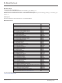
5HODWHG'RFXPHQWV
7LWOHRI'RFXPHQWDWLRQ
5HIHUHQFH1XPEHU
ATV61 Quick Start guide
S1B86974
ATV71 Quick Start guide
S1B86982
ATV61 > 75kW Installation manual
1760655
ATV71 > 75kW Installation manual
1755849
ATV61 0,37kW to 75 kW Installation manual
1760643
ATV71 0,37kW to 75 kW Installation manual
1755843
ATV61 Programming manual
1760649
ATV71 Programming manual
1755855
ATV71 S383 Programming manual
AAV49426
ATV71 Communication Parameters manual
1755861
ATV61 Communication parameters manual
1760661
ATV71 Integrated Modbus manual
1755863
ATV71 Modbus Plus manual
1755869
ATV71 Uni-Telway manual
1755867
ATV71 Modbus with Uni-Telway manual
1755875
ATV61/71 CC-Link manual
AAV49429
ATV61/71 Standard Fipio manual
1755883
ATV61 LonWorks card manual
1765273
ATV61 BACnet manual
1765274
ATV61/71 DeviceNet manual
1755877
ATV61 Metasys N2 manual
AAV33578
ATV61 APOGEE FLN P1 manual
BBV10543
ATV61/71 INTERBUS manual
1755871
ATV61/71 Profibus DP manual
1755873
ATV61/71 Profibus DPv1 manual
AAV52935
ATV61/71 Controller Inside manual
1757062
ATV61/71 CANopen manual
1755865
ATV61/71 EtherNet-IP manual
AAV68822
ATV61/71 Ethernet - Modbus TCP-IP manual
1755879
ATV61/71 Modbus TCP-IP manual - Daisy Chain Ethernet card manual
AAV69931
ATV61/71 ModbusTCP manual_VW3A3320
HRB10064
ATV61/71 EthernetIP manual VW3A3320
HRB10065
ATV61/71 LIFT Safety integrated function manual
S1A91443
ATV61/71 certificates, see www.schneider-electric.com
You can download the latest versions of these technical publications and other technical information from
www.schneider-electric.com.
HRB10065 02/2013
5
efesotomasyon.com
%HIRUH\RXEHJLQ
'$1*(5
81,17(1'('(48,30(1723(5$7,21
• Read and understand this manual before installing or operating the drive.
• Any changes made to the parameter settings must be performed by qualified personnel.
)DLOXUHWRIROORZWKHVHLQVWUXFWLRQVZLOOUHVXOWLQGHDWKRUVHULRXVLQMXU\
'$1*(5
+$=$5'2)(/(&75,&6+2&.(;3/26,2125$5&)/$6+
• Only appropriately trained persons who are familiar with and understand the contents of this manual and all other pertinent product
documentation and who have received safety training to recognize and avoid hazards involved are authorized to work on and with this
product system. Installation, adjustment, repair and maintenance must be performed by qualified personnel.
• The system integrator is responsible for compliance with all local and national electrical code requirements as well as all other
applicable regulations with respect to grounding of all equipment.
• Many components of the product, including the printed circuit boards, operate with mains voltage. Do not touch. Use only electrically
insulated tools.
• Do not touch unshielded components or terminals with voltage present.
• Motors can generate voltage when the shaft is rotated. Prior to performing any type of work on the product system, block the motor
shaft to prevent rotation.
• AC voltage can couple voltage to unused conductors in the motor cable. Insulate both ends of unused conductors of the motor cable.
• Do not short across the DC bus terminals or the DC bus capacitors or the braking resistor terminals.
• Before performing work on the product system:
- Disconnect all power, including external control power that may be present.
- Place a "Do Not Turn On" label on all power switches.
- Lock all power switches in the open position.
- Wait 15 minutes to allow the DC bus capacitors to discharge. The DC bus LED is not an indicator of the absence of DC bus voltage
that can exceed 800 Vdc.
Measure the voltage on the DC bus between the DC bus terminals using a properly rated voltmeter to verify that the voltage is <42
Vdc.
- If the DC bus capacitors do not discharge properly, contact your local Schneider Electric representative.
• Install and close all covers before applying voltage.
)DLOXUHWRIROORZWKHVHLQVWUXFWLRQVZLOOUHVXOWLQGHDWKRUVHULRXVLQMXU\
:$51,1*
'$0$*('5,9((48,30(17
Do not operate or install any drive or drive accessory that appears damaged.
)DLOXUHWRIROORZWKHVHLQVWUXFWLRQVFDQUHVXOWLQGHDWKVHULRXVLQMXU\RUHTXLSPHQWGDPDJH
:$51,1*
/2662)&21752/
• The designer of any wiring scheme must consider the potential failure modes of control channels and, for certain critical control
functions, provide a means to achieve a safe state during and after a channel failure. Examples of critical control functions are
emergency stop and overtravel stop.
• Separate or redundant control paths must be provided for critical control functions.
• System control channels may include links carried out by the communication. Consideration must be given to the implications
of unanticipated transmission delays or failures of the link.(1)
)DLOXUHWRIROORZWKHVHLQVWUXFWLRQVFDQUHVXOWLQGHDWKVHULRXVLQMXU\RUHTXLSPHQWGDPDJH
(1) For additional information, refer to NEMA ICS 1.1 (latest edition), “Safety Guidelines for the Application, Installation, and Maintenance of Solid
State Control” and to NEMA ICS 7.1 (latest edition), “Safety Standards for Construction and Guide for Selection, Installation and Operation of
Adjustable-Speed Drive Systems.”
6
HRB10065 02/2013
efesotomasyon.com
'RFXPHQWDWLRQVWUXFWXUH
The following Altivar 61/71 technical documents are available on the Web site www.schneider-electric.com.
b,QVWDOODWLRQ0DQXDO
This manual describes:
• How to assemble the drive.
• How to connect the drive.
b3URJUDPPLQJ0DQXDO
This manual describes:
• The functions.
• The parameters.
• How to use the drive display terminal (integrated display terminal and graphic display terminal).
b&RPPXQLFDWLRQ3DUDPHWHUV0DQXDO
This manual describes:
• The drive parameters with specific information (addresses, formats, etc.) for use via a bus or communication network.
• The operating modes specific to communication (state chart).
• The interaction between communication and local control.
b0RGEXV&$1RSHQ(WKHU1HW3URILEXV,17(5%868QL7HOZD\'HYLFH1HW
0RGEXV3OXV HWFPDQXDOV
These manuals describe:
• Connection to the bus or network.
• Configuration of the communication-specific parameters via the integrated display terminal or the graphic display terminal.
• Diagnostics.
• Software setup.
• The communication services specific to the protocol.
b$OWLYDU)0LJUDWLRQ0DQXDO
This manual describes the differences between the Altivar 71 and the Altivar 58/58F.
It explains how to replace an Altivar 58 or 58F, including how to replace drives communicating on a bus or network.
HRB10065 02/2013
7
efesotomasyon.com
,QWURGXFWLRQ
3UHVHQWDWLRQ
The EtherNet/IP card (catalog number VW3 A3320) is used to connect an Altivar 61/71 drive to an Ethernet network using the EtherNet/IP
protocol.
This communication option card is fully supported with the version V5.7 and above of the Altivar 61 firmware and with the version V5.8 and
above of Altivar 71 firmware.
The VW3 A3320 card is equipped with two shielded RJ45 EtherNet connectors.
The accessories for connection to the EtherNet/IP network must be ordered separately.
The data exchanges permit full drive functionality:
• Configuration
• Adjustment
• Control
• Monitoring
• Diagnostics
The standard Web server (English only) provides access to the following pages:
• Monitoring
• Diagniostics
• Setup
• RSTP management
The standard Web server can be adapted or replaced by a customized server depending on the requirements of the application.
The graphic display terminal or the integrated display terminal can be used to access numerous functions for communication diagnostics.
1RWDWLRQ
'ULYHWHUPLQDOGLVSOD\V
The graphic display terminal menus are shown in square brackets.
Example: [1.9 COMMUNICATION].
The integrated 7-segment display terminal menus are shown in round brackets.
Example: (COM-).
The parameter names displayed on the graphic display terminal are shown in square brackets.
Example: [Fallback speed].
The parameter codes displayed on the integrated 7-segment display terminal are shown in round brackets.
Example: (LFF).
)RUPDWV
Hexadecimal values are written as follows: 16#
Binary values are written as follows: 2#
PC-Software: Commissioning Software
8
HRB10065 02/2013
efesotomasyon.com
+DUGZDUHVHWXS
5HFHLSW
• Check that the card catalog number marked on the label is the same as that on the delivery note corresponding to the purchase order.
• Remove the option card from its packaging and check that it has not been damaged in transit.
&$87,21
67$7,&6(16,7,9(&20321(176
The EtherNet/IP card can be damaged by static electricity. Observe electrostatic precautions when handling and
installing the card.
)DLOXUHWRIROORZWKLVLQVWUXFWLRQFDQUHVXOWLQHTXLSPHQWGDPDJH
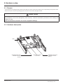
+DUGZDUHGHVFULSWLRQ
LEDs
Shielded female RJ45
EtherNet connector
(Port 2)
MAC address label
on the card
Shielded female RJ45
EtherNet connector
(Port 1)
HRB10065 02/2013
9
efesotomasyon.com
+DUGZDUHVHWXS
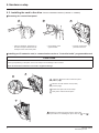
,QVWDOOLQJWKHFDUGLQWKHGULYHSee the Installation Manual (1760643 or 1760655).
b5HPRYLQJWKHFRQWUROIURQWSDQHO
• Using a screwdriver, press down on
the catch and pull to release the lefthand part of the control front panel
• Do the same on the
right-hand side
• Pivot the control front
panel and remove it
b,QVWDOOLQJDQ,2H[WHQVLRQFDUGDFRPPXQLFDWLRQFDUGRUD³&RQWUROOHU,QVLGH´SURJUDPPDEOHFDUG
&$87,21
5,6.2)'$0$*(727+(&211(&725
Ensure good positioning of the option card on the clasps to avoid damage to the connector.
)DLOXUHWRIROORZWKHVHLQVWUXFWLRQVFDQUHVXOWLQHTXLSPHQWGDPDJH
1 , 2 and 3 Remove the control front panel
(see previous page)
4 Install an encoder interface card (if used)
(see previous page)
5 Position the option card on the clasps
6 Then pivot it until it clicks into place
7 Replace the control front panel over the option card
(same procedure as for installing the option card, see 5 and
10
6 )
HRB10065 02/2013
efesotomasyon.com
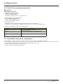
&RQQHFWLQJWRWKH(WKHU1HW,3QHWZRUN
&DUG5-FRQQHFWRUSLQRXW
The EtherNet/IP card is equipped with two shielded RJ45 connectors. The shielding is connected to the drive ground. The dielectric isolation
is 1500Vrms.
Use an STP (shielded twisted pair) EtherNet/IP cable.
3LQ
6LJQDO
1
TD+
2
TD-
3
RD+
4
5
6
RD-
7
8........................1
8........................1
8
The transmission speed is detected automatically by the card (10 Mbps or 100 Mbps).
The card can operate in half duplex or full duplex mode, whether connected to a hub or a switch and regardless of the transmission speed
(10 Mbps or 100 Mbps). Devices of the network shall be all set to the same baudrate manually or all set to automatic bauderate detection.
1RWHRSTP function is not compatible with half duplex configuration. All devices involved in the RSTP topology shall be RSTP capable and
configured.
([DPSOHRIFRQQHFWLRQWRDQ(WKHU1HW,3QHWZRUN
PLC
Daisy chain and/or star topology
ATV61/71 ATV61/71 ATV61/71 ATV61/71 ATV61/71
Ethernet switch
1RWH: When the topology is a daisy chain, if one drive is turned off, the drive(s) next the drive powered off trip in CNF. To keep the integrity
of the Ethernet daisy chain network even if one or several drives are powered off, it is mandatory to add an external permanent 24VDc
supply for the drives control bloc.
PLC
Redundant ring topology with RSTP
ATV61/71 ATV61/71 ATV61/71 ATV61/71 ATV61/71
Ethernet switch with RSTP managment
HRB10065 02/2013
11
efesotomasyon.com
&RQQHFWLQJWRWKH(WKHU1HW,3QHWZRUN
PLC with embedded
RSTP management
(M340 + NOC401)
Redundant ring topology with RSTP
ATV61/71 ATV61/71 ATV61/71 ATV61/71 ATV61/71
Redundant star topology with RSTP
PLC with embedded RSTP management
(M340 + NOC401)
ATV61/71
ATV61/71
ATV61/71
Ethernet switch
with RSTP managment
Ethernet switch
with RSTP managment
ATV61/71
12
HRB10065 02/2013
efesotomasyon.com
(WKHUQHWPHQX
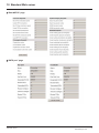
$FFHVVWR(WKHU1HWPHQXYLDJUDSKLFGLVSOD\WHUPLQDO
The [ETHERNET RSTP] (EtHrS) submenu is used to configure and display the EtherNet/IP card parameters and can be accessed via
the [1.9 COMMUNICATION] menu.
This menu is only accessible in standard, advanced and expert mode: In the [2 ACCESS LEVEL] (LAC-) menu, set the level to [expert]
(EPr).
Can be accessed by the other level.
RDY
RDY
NET +0.00 Hz
MAIN MENU
1 DRIVE MENU
2 ACCESS LEVEL
3 OPEN / SAVE AS
4 PASSWORD
5 LANGUAGE
Code
0A
ENT
Quick
NET +0.00 Hz
0A
1 DRIVE MENU
1.1 SIMPLY START
1.2 MONITORING
1.3 SETTINGS
1.4 MOTOR CONTROL
1.5 INPUTS/OUTPUTS CFG
Code
<<
>>
Quick
1.6 COMMAND
1.7 APPLICATION FUNCT.
1.8 FAULT MANAGEMENT
1.9 COMMUNICATION
1.10 DIAGNOSTICS
1.11 IDENTIFICATION
1.12 FACTORY SETTINGS
1.13 USER MENU
1.14 PROGRAMMABLE CARD
RUN
ENT
NET
+50.00 Hz 80A
1.9 COMMUNICATION
COM. SCANNER OUTPUT
MODBUS HMI
MODBUS NETWORK
CANopen
EtherNET RSTP
Code
<<
>>
Quick
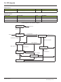
$FFHVVWR(WKHU1HWPHQXYLDWKHLQWHJUDWHGGLVSOD\WHUPLQDO
The (EtH-) submenu is used to configure and display the EtherNet/IP card parameters. It can be accessed via the (COM-) menu.
Power-up
XXX
Displays the drive state
ENT
ESC
SIM-
ESC
FLtENT
ESC
EtH-
CONESC
ESC
FCS-
ESC
LAC-
HRB10065 02/2013
13
efesotomasyon.com
(WKHUQHWPHQX
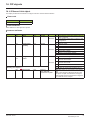
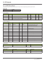
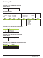
(WKHUQHW,3FRQILJXUDWLRQZLWKWKH+0,
Detail of the Ethernet/IP configuration menu: (All these settings can also be performed from the webserver or PC-Software). In the table,
parameters which are not followed by their parameter code (between parenthesis) are not displayed on the 7 segment display of the drive.
[1.9 - COMMUNICATION] (COM-) V menu [ETHERNET RSTP] (EthrS)
3DUDPHWHU
[Rate Setting Right] (rdSr)
3RVVLEOHYDOXH
0 : Autodetect (default)
1 : 10 Mbps Full
This field is used to set the transmission
2 : 10 Mbps Half
speed and the transmission mode of the
3 : 100 Mbps Full
card for the right port
4 : 100 Mbps Half (do not use)
[Rate Setting] (rdS)
0 : Autodetect (default)
1 : 10 Mbps Full
This field is used to set the transmission
speed and the transmission mode of the card 2 : 10 Mbps Half
3 : 100 Mbps Full
for the left port.
4 : 100 Mbps Half (do not use)
[Actual Rate Right] (Ardr)
0 : Autodetect
1 : 10 Mbps Full
This field displays the baud rate and the
2 : 10 Mbps Half
transmission mode currently used by the
3 : 100 Mbps Full
communication card for the right port.
(Display only)
4 : 100 Mbps Half
[Actual Rate] (Ard)
0 : Autodetect
1 : 10 Mbps Full
This field displays the baud rate and the
2 : 10 Mbps Half
transmission mode currently used by the
communication card for the left port. (Display 3 : 100 Mbps Full
only)
4 : 100 Mbps Half
[DEVICE NAME]
16 chars.
The device name is required if the card uses
DHCP to obtain its IP Address.
[Ethernet protocol] (EtHM)
0: ModbusTCP (default)
Use this parameter to select the protocol.
1: EthernetIP
[IP mode] (IpM )
0 : Manu
1 : BOOTP (default value is DHCP)
Use this parameter to select the IP address
2 : DHCP
assignment method.
[IP card] (IPC-)
(IPC1) (IPC2)
(IPC3) (IPC4)
IP address of the card
[IP Mask] (IPN-)
(IPM1) (IPM2)
(IPM3) (IPM4)
Subnet mask
[IP Gate] (IPG-)
(IPG1) (IPG2)
(IPG3) (IPG4)
Gateway IP address
[ModbusTCP] (MbtP)
[EthernetIP] (EtIP)
[Fixed] (MAnU)
[BOOTP] (bOOt)
[DHCP] (dHCP)
These fields are editable when IP mode is set to Fixed [139.160.069.241]
address
(139) (160) (069) (241)
These fields are editable when IP mode is set to Fixed [255.255.254.0]
address
(255) (255) (254) (0)
These fields are editable when IP mode is set to Fixed [0.0.0.0]
address
(0) (0) (0) (0)
It could be necessary to set a gateway address if Email
servicies are uses.
• If the address has been given by a BOOTP or a DHCP server, these fields are read only.
• After dynamic addressing by a BOOTP or DHCP server, the new address value is displayed.
[Services] (E E)
0 : Web Server and Email functions are disabled.
Enables web server and e-mail server
1: Web Server activated.
This parameter is significant at the bit level. 2: Email function activated
3: Web server and Email functions are activated
Bit 0 and bit 1, other bits are reserved
14
7HUPLQDOGLVSOD\
[Auto] (AUtO)
[10 Mbps full] (10 F)
[10 Mbps half] (10H)
[100 Mbps full] (100F)
[100 Mbps half] (100H)
[Auto] (AUtO)
[10 Mbps full] (10 F)
[10 Mbps half] (10H)
[100 Mbps full] (100F)
[100 Mbps half] (100H)
[Auto] (AUtO)
[10 Mbps full] (10 F)
[10 Mbps half] (10H)
[100 Mbps full] (100F)
[100 Mbps half] (100H)
[Auto] (AUtO)
[10 Mbps full] (10 F)
[10 Mbps half] (10H)
[100 Mbps full] (100F)
[100 Mbps half] (100H)
[ABC… ]
0
1
2
3
HRB10065 02/2013
efesotomasyon.com
(WKHUQHWPHQX
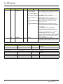
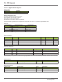
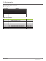
(WKHUQHW,3FRQILJXUDWLRQZLWKWKH+0,FRQWLQXHG
3DUDPHWHU
[Config. Assembly] (CIO3)
Configured Input/Output assembly
(Read only)
[MAC @]
MAC address display
3RVVLEOHYDOXH
0: 20/70
1: 21/71
2: 22/72
3: 23/73
4: 100/101
5: 103/104
6: UnCG (default)
[00-80-F4-XX-XX-XX]
7HUPLQDOGLVSOD\
[20/70] (20/70)
[21/71] (21/71)
[22/72] (22/72)
[23/73] (23/73)
[100/101] (100/101)
[103/104] (103/104)
[Unconfig.] (UnCG)
[00-80-F4-XX-XX-XX]
HRB10065 02/2013
15
efesotomasyon.com
(WKHUQHWPHQX
'HWDLORIWKHFRQILJXUHGSDUDPHWHUV
b,3DGGUHVV
$VVLJQLQJ,3DGGUHVVHV
3 IP parameters shall be configured:
• The drive IP address (Mandatory)
• The subnet mask (Mandatory)
• The gateway IP address (Optional - for E-Mail service).
These IP addresses can be entered directly:
• Using the integrated display terminal.
• Using the graphic display terminal.
• Or using the PC-Software workshop.
They can be provided by:
• A BOOTP server (correspondence between the MAC address and the IP addresses).
• Or a DHCP server (correspondence between Device Name [DEVICE NAME] and the IP addresses).
The address is assigned according to the IPmode parameter:
,30RGHYDOXH
IP mode = 0
IP mode = 1
&RPPHQWV
The card uses the address defined in
IPC1, IPC2, IPC3, IPC4
The card receives its address from a BOOTP server
IP mode = 2
The card receives its address from a DHCP server
And Device name contains a valid name.
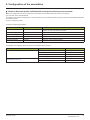
$VVHPEOLHVDQGVFDQQHUFRQILJXUDWLRQ
The assemblies are chosen at the master controller level (see for example chapter 16 Integration in RSlogix).
For the 4 ODVA set of assemblies (20,21,22,23,70,71,72,73) there are no more configuration to do at the communication scanner level.
For the Schneider-Electric assembly (100,101) and Allen Bradley® assembly (103,104):
• configure at the drive level the size of the assembly,
• define the mapping of the additional parameters.
16
HRB10065 02/2013
efesotomasyon.com
&RQILJXUDWLRQRIWKHDVVHPEOLHV
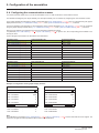
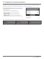
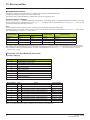
&RQILJXUDWLRQRIWKHDVVHPEOLHVRYHUYLHZ
9:$(WKHU1HW,3FRPPXQLFDWLRQFDUG
)HDWXUHVRYHUYLHZ
6WDQGDUG
:HE
EURZVHU
,(0R]LOOD
(WKHU1HW,3&\FOLFH[FKDQJHV
(WKHU1HW,3DF\FOLFPHVVDJHV
0DVWHU
&RQWUROOHU
,2
6FDQQHU
Assemblies
20 - 70
&,3EDVLFVSHHGFRQWURO
SURILOH
Assemblies
21 - 71
&,3H[WHQGHGVSHHGFRQWURO
SURILOH
Assemblies
22 - 72
&,3VSHHGDQGWRUTXH
&RQWUROSURILOH
Assemblies
23 - 73
&,3H[WHQGHGVSHHGDQGWRUTXH
&RQWUROSURILOH
Assemblies
100 - 101
6FKQHLGHU(OHFWULFQDWLYHGULYH
3URILOH
Assemblies
103 - 104
$OOHQ%UDGOH\GULYH
SURILOH
CIP
Explicit
messaging
3DUDPHWHUV
PDQDJHPHQW
Embedded
Web server
'ULYHVHWXS
HRB10065 02/2013
17
efesotomasyon.com
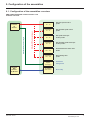
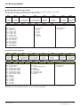
&RQILJXUDWLRQRIWKHDVVHPEOLHV
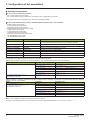
&RQILJXUDWLRQRIWKHDVVHPEO\6FKQHLGHU(OHFWULFQDWLYHSURILOH
The size of the assembly is fixed and is equal to 8.
The mapping of the other parameters is made with the communication scanner :
The configuration of the addresses defined with NCAx and NMAx can be made with the graphic keypad:
For assembly 100 : [1.9- COMMUNICATION] (COM-) menu, [COM.SCANNER OUTPUT] (OCS-) submenu.
For assembly 101 : [1.9- COMMUNICATION] (COM-) menu, [COM.SCANNER INPUT] (ICS-) submenu.
See menu [1.2 MONITORING] > COMMUNICATION MAP to monitor the communication scanner.
See also "Configuring the communication scanner" page 20.
EtherNet/IP
scanner
EtherNet/IP option
VW3 A3320
Altivar 71/61
The mapping of the 100-101
Assemblies is made with the ATV61/71
communication scanner
100-101
Native drive profile
CiA402
NCA1
NCA2
NCA3
NCA4
NCA5
NCA6
NCA7
NCA8
NMA1
NMA2
NMA3
NMA4
NMA5
NMA6
NMA7
NMA8
$VVHPEO\
$VVHPEO\
Up to 8 additional
parameters are
mapped.
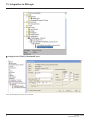
This configuration is made with:
• HMI
• PC-Software
• Keypad
Here is an example of the configuration of the assemblies 100, 101 from RSLogix software:
Fixed size
18
HRB10065 02/2013
efesotomasyon.com
&RQILJXUDWLRQRIWKHDVVHPEOLHV
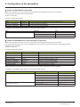
&RQILJXUDWLRQRIWKHDVVHPEO\$OOHQ%UDGOH\SURILOH
The size of the assembly is selectable from 2 to 10 words.
The 2 first words of the input assembly are fixed: Control word, Speed setpoint.
The 2 first words of the output assembly are fixed: Status word, Actual Speed.
1&$DQG1&$DUHDOUHDG\FRQILJXUHGGHIDXOWVHWWLQJVRIWKHGULYH:KHQFRQILJXULQJWKLVDVVHPEO\VHWWRKDQGO\UHPRYHWKH
GHIDXOWDVVLJQPHQWRI1&$DQG1&$%\VHWWLQJ1&$DQG1&$WRDQXOODGGUHVVRUE\FRQILJXULQJWKLVWZRDGGUHVVWRRWKHU
UHTXLUHGSDUDPHWHUVRIWKHGULYH
This will avoid a conflict between NCA1 and the control word of the profile (located in the first word of the assembly 103).
The configuration of the addresses defined with NCAx and NMAx can be made with the graphic keypad:
For assembly 103 : [1.9- COMMUNICATION] (COM-) menu, [COM.SCANNER OUTPUT] (OCS-) submenu.
For assembly 104 : [1.9- COMMUNICATION] (COM-) menu, [COM.SCANNER INPUT] (ICS-) submenu.
See menu [1.2 MONITORING] > COMMUNICATION MAP to monitor the communication scanner.
See also "Configuring the communication scanner" page 20
The mapping of the other parameters is made with the EtherNet/IP scanner:
EtherNet/IP
scanner
EtherNet/IP option
VW3 A3320
Altivar 71/61
The mapping of the 103-104
Assemblies is made with the
option card EtherNet/IP scanner
103-104
Native drive profile
CiA402
This configuration is
made with:
• Webserver
• PC-Software
Control Word Status Word
Set point
Actual speed
NCA1
NMA1
NCA2
NMA2
NCA3
NMA3
NCA4
NMA4
NCA5
NMA5
NCA6
NMA6
NCA7
NMA7
NCA8
NMA8
$VVHPEO\
$VVHPEO\
Up to 8 additional
parameters are mapped.
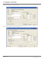
Here is an example of the configuration of the assemblies 103, 104 from RSLogix software
The sizes indicated must be
adjusted according to the
settings defined with the
EtherNet/IP scanner setup
(webserver or PC-Software).
1RWH
• The size of the assembly
cannot be modified
dynamically; such change
requires a power ON.
• Given that assemblies 103
and 104 uses NCAx and
NMAx, the configuration
edited with the webserver
or PC-Software are also
applied to the
communication scanner of
the drive (like assemblies
100 and 101).
HRB10065 02/2013
19
efesotomasyon.com
&RQILJXUDWLRQRIWKHDVVHPEOLHV
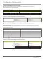
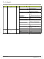
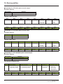
&RQILJXULQJWKHFRPPXQLFDWLRQVFDQQHU
You need to read this chapter only if you use the assemblies 100 or 101 that use the drive communication scanner.
The variables exchanged by the output assembly 100 and input assembly 101 are selected by configuring the communication scanner.
The 8 output variables are assigned by means of the 8 parameters [Scan. Outp address] (nCAp). They are configured using the graphic
display terminal via the [1.9 - COMMUNICATION] (COM-) menu, [COM. SCANNER OUTPUT] (OCS-) submenu.
The 8 input variables of the assembly 101 are assigned by means of the 8 parameters [Scan. Inp address] (nMAp). They are configured
using the graphic display terminal via the [1.9 - COMMUNICATION] (COM-) menu, [COM. SCANNER INPUT] (ICS-) submenu.
Enter the logic address of the parameter (see the Communication parameters manual).
If a parameter [Scan. Outp address] (nCAp) or [Scan. Inp address] (nMAp) is equal to zero, the corresponding period variable is not
used by the drive.
These 8 assignment parameters are described in the tables below:
3DUDPHWHUQDPH
2XWSXWDVVHPEO\
'HIDXOWDVVLJQPHQW
[Scan. Out1 address] (nCA1)
NCA1 = 8501
[Scan. Out2 address] (nCA2)
NCA2 = 8602
[Scan. Out3 address] (nCA3)
NCA3 = not used
[Scan. Out4 address] (nCA4)
NCA4 = not used
[Scan. Out5 address] (nCA5)
NCA5 = not used
[Scan. Out6 address] (nCA6)
NCA6 = not used
[Scan. Out7 address] (nCA7)
NCA7 = not used
[Scan. Out8 address] (nCA8)
NCA8 = not used
3DUDPHWHUQDPH
,QSXWDVVHPEO\
'HIDXOWDVVLJQPHQW
[Scan. In1 address] (nMA1)
NMA1=3201
[Scan. In2 address] (nMA2)
NMA2=8604
[Scan. In3 address] (nMA3)
NMA3=not used
[Scan. In4 address] (nMA4)
NMA4=not used
[Scan. In5 address] (nMA5)
NMA5=not used
[Scan. In6 address] (nMA6)
NMA6=not used
[Scan. In7 address] (nMA7)
NMA7=not used
[Scan. In8 address] (nMA8)
NMA8=not used
([DPSOHRIFRQILJXUDWLRQYLDWKHJUDSKLFGLVSOD\WHUPLQDO
RDY
NET
+0.00Hz
0A
RDY
COM. SCANNER INPUT
NET
+0.00Hz
0A
COM. SCANNER OUTPUT
Scan. In1 address
:
3204
Scan. Out1 address
:
9001
Scan. In2 address
:
3206
Scan. Out2 address
:
9002
Scan. In3 address
:
0
Scan. Out3 address
:
0
Scan. In4 address
:
0
Scan. Out4 address
:
0
Scan. In5 address
:
0
Scan. Out5 address
:
0
Code
Quick
Code
Quick
Scan. In6 address
:
0
Scan. Out6 address
:
0
Scan. In7 address
:
0
Scan. Out7 address
:
0
Scan. In8 address
:
0
Scan. Out8 address
:
0
1RWH
All modifications to parameters [Scan. Outp address] (nCAp) or [Scan. Inp address] (nMAp) must be made with the motor stopped. The
master PLC program should be updated to take account of this modification.
20
HRB10065 02/2013
efesotomasyon.com
&RQILJXUDWLRQRIWKHDVVHPEOLHV
&RQILJXULQJWKHFRQWURO
b 3ULQFLSOH
By the configuration of the control, it is possible to decide from what channel the drive receives its commands and setpoint, either
permanently or depending on a switching command.
Numerous configurations are possible. For more information, refer to the Programming manual and Communication parameters manual.
The following configurations are some of the possibilities available.
M &RQWUROZLWKFRPPXQLFDWLRQVFDQQHU
If the default assemblies (100, 101) are selected, all possibilities of Altivar 61/71 drive are available.
It is possible to use all profiles and modes of the drive:
- I/O profile,
- Drivecom profiles with separate or non separate mode.
By the configuration of the communication scanner, it is possible to assign any relevant parameter of the drive to the 8 input and 8 output
variables of the assemblies.
See the input / output interface with the PLC can be fully customised depending on the application.
The use of the communication scanner is also the best way to interface with a "Controller Inside" card.
M &RQWURODFFRUGLQJWR2'9$$&GULYHSURILOH
The ODVA AC drive profile is activated when one of the following assemblies is selected:
• 20: Basic speed control output
• 21: Extended speed control output
• 22: Speed and torque control output
• 23: Extended speed and torque control output
• 70: Basic speed control input
• 71: Extended speed control input
• 72: Speed and torque control input
• 73: Extended speed and torque control input
The advantage of using the ODVA drive profile standard is the interchangeability with other brands.
The drive must be configured in the Drivecom profile with separate mode.
The EtherNet/IP card translates the commands, behaviour and monitoring information from ODVA profile (on the network) to the Drivecom
profile (in the drive).
M &RQWURODFFRUGLQJWR$OOHQ%UDGOH\GULYHSURILOH
The Allen-Bradley® Drive profile is activated when one of the following assemblies is selected:
• 103: Allen-Bradley® drive output
• 104: Allen-Bradley® drive input
If you need to replace Allen-Bradley® drives, in an existing application, this profile is a good way to minimise the modifications.
The drive must be configured in the Drivecom profile with separate mode.
The EtherNet/IP card translates the commands, behaviour and monitoring information from Allen-Bradley® drive profile (on the network) to
the Drivecom profile (in the drive).
HRB10065 02/2013
21
efesotomasyon.com
&RQILJXUDWLRQRIWKHDVVHPEOLHV
b $YDLODEOHFRQILJXUDWLRQV
M ,I\RXXVHWKHFRPPXQLFDWLRQVFDQQHU
• 100: Communication scanner output
• 101: Communication scanner input there is no limitation in the configuration of the control.
The examples below are only possible if you use the communication scanner.
M ,I\RXXVHWKH2'9$$&GULYHSURILOHRU$OOHQ%UDGOH\'ULYHSURILOHWKDWLVWKHDVVHPEOLHV
•
•
•
•
•
•
•
•
•
•
20: Basic speed control output
21: Extended speed control output
22: Speed and torque control output
23: Extended speed and torque control output
70: Basic speed control input
71: Extended speed control input
72: Speed and torque control input
73: Extended speed and torque control input
103: Allen-Bradley® drive output
104: Allen-Bradley® drive input
3DUDPHWHU
Profile
3HUPLWWHGYDOXH
Drivecom profile separate
Setpoint 1 configuration
Setpoint 1B configuration
Setpoint 2 configuration
Command 1 configuration
Command 2 configuration
Command switching
Setpoint switching
Network card
Terminals
Terminals
Network card
Terminals
Network card bit 12
Network card bit 13
&RPPHQW
The run commands are in Drivecom profile,
the command and the reference can come from different channels.
Setpoint 1 comes from EtherNet/IP.
Setpoint 2 comes from terminals (AI1 or AI2).
Setpoint 2 comes from terminals (AI1 or AI2).
Command 1 comes from EtherNet/IP.
Command 2 comes from terminals.
Bit 12 of the control word switches the command.
Bit 13 of the control word switches the setpoint (1 <-> 1B or 1 <-> 2).
Configuration via the graphic display terminal or the integrated display terminal:
&DVH Setpoint 1B is connected to the functions (Summing, PID, etc) which remain active even after switching.
0HQX
3DUDPHWHU
3HUPLWWHGYDOXH
[1.6 - COMMAND] (CtL-)
[Profile] (CHCF)
[Separate] (SEP)
[Ref.1 channel] (Fr1)
[Com. card] (nEt)
[Ref.1B channel] (Fr1b)
[Ref. AI1] (AI1) or [Ref. AI2] (AI2)
[Cmd channel 1] (Cd1)
[Com. card] (nEt)
[Cmd channel 2] (Cd2)
[Terminals] (tEr)
[Cmd switching] (CCS)
[C312] (C312)
[1.7 APPLICATION FUNCT.] (FUn-)
[Ref 1B switching] (rCb)
[C313] (C313)
[REFERENCE SWITCH.]
&DVH Setpoint 2 is directly connected to the drive reference limit. If switching is performed, the functions that affect the reference
(summing, PID, etc.) are inhibited.
0HQX
3DUDPHWHU
3HUPLWWHGYDOXH
[1.6 - COMMAND] (CtL-)
[Profile] (CHCF)
[Separate] (SEP)
[1.7 APPLICATION FUNCT.] (FUn-)
[Ref.1 channel] (Fr1)
[Com. card] (nEt)
[REFERENCE SWITCH.]
[Ref.2 channel] (Fr2)
[Ref. AI1] (AI1) or [Ref. AI2] (AI2)
[Cmd channel 1] (Cd1)
[Com. card] (nEt)
[Cmd channel 2] (Cd2)
[Terminals] (tEr)
[Cmd switching] (CCS)
[C312] (C312)
[Ref. 2 switching] (rFC)
[C313] (C313)
1RWH It is not possible to configure the display terminal as a channel.
To switch to the display terminal, use the function force local and assign the parameter [Forced local Ref.] to [HMI] (LCC).
22
HRB10065 02/2013
efesotomasyon.com
&RQILJXUDWLRQRIWKHDVVHPEOLHV
b &RQWUROYLD(WKHU1HW,3LQ,2SURILOH
1RWH This configuration can only be used if the communication scanner assemblies (100 and 101) are selected.
The command and the setpoint come from EtherNet/IP.
Control is in I/O profile.
Configure the following parameters:
3DUDPHWHU
9DOXH
&RPPHQW
Profile
I/O profile
The run command is simply obtained by bit 0 of the command word.
Setpoint 1 configuration
Network card The setpoint comes from EtherNet/IP.
Command 1 configuration
Network card The command comes from EtherNet/IP.
Configuration via the graphic display terminal or the integrated display terminal:
0HQX
[1.6 - COMMAND] (CtL-)
3DUDPHWHU
9DOXH
[Profile] (CHCF)
[I/O profile] (IO)
[Ref.1 channel] (Fr1)
[Com. card] (nEt)
[Cmd channel 1] (Cd1)
[Com. opt card] (nEt)
b &RQWUROYLD(WKHU1HW,3RUYLDWKHWHUPLQDOVLQ,2SURILOH
1RWH This configuration can only be used if the communication scanner assemblies (100 and 101) are selected.
The command and the setpoint both come from EtherNet/IP or the terminals. Input LI5 at the terminals is used to switch between
EtherNet/IP and the terminals.
Control is in I/O profile.
Configure the following parameters:
3DUDPHWHU
9DOXH
Profile
I/O profile
&RPPHQW
The run command is simply obtained by bit 0 of the control word.
Setpoint 1 configuration
Network card
Setpoint 1 comes from EtherNet/IP.
Setpoint 1B configuration
Analog input 1 on the terminals Setpoint 1B comes from input AI1 on the terminals.
Setpoint switching
Input LI5
Input LI5 switches the setpoint (1l1B).
Command 1 configuration
Network card
Command 1 comes from EtherNet/IP.
Command 2 configuration
Terminals
Command 2 comes from the terminals.
Command switching
Input LI5
Input LI5 switches the command.
1RWH Setpoint 1B is connected to the functions (Summing, PID, etc) which remain active even after switching.
Configuration via the graphic display terminal or the integrated display terminal:
0HQX
3DUDPHWHU
[1.6 - COMMAND] (CtL-)
[Profile] (CHCF)
[I/O profile] (IO)
[Ref.1 chan] (Fr1)
[Com. card] (nEt)
[Cmd channel 1] (Cd1)
[Com. card] (nEt)
[Cmd channel 2] (Cd2)
[Terminals] (tEr)
[Cmd switching] (CCS)
[LI5] (LI5)
[Ref.1B chan] (Fr1b)
[AI1 ref.] (AI1)
[Ref 1B switching] (rCb)
[LI5] (LI5)
[1.7 APPLICATION FUNCT.] (FUn-)
[REFERENCE SWITCH.]
9DOXH
HRB10065 02/2013
23
efesotomasyon.com
&RQILJXUDWLRQRIWKHDVVHPEOLHV
b &RQWUROYLD(WKHU1HW,3LQ'ULYHFRPSURILOH
1RWHThis configuration can only be used if the communication scanner assemblies (100 and 101) are selected.
The command and the setpoint come from EtherNet/IP.
Configure the following parameters:
3DUDPHWHU
9DOXH
&RPPHQW
Profile
Separate Drivecom profile
The run commands are in Drivecom profile, the command and the setpoint can
come from different channels.
Setpoint 1 configuration
Network card
The setpoint comes from EtherNet/IP.
Command 1 configuration
Network card
Command 1 comes from EtherNet/IP.
Configuration via the graphic display terminal or the integrated display terminal:
0HQX
3DUDPHWHU
9DOXH
[1.6 - COMMAND] (CtL-)
[Profile] (CHCF)
[Separate] (SEP)
[Ref.1 chan] (Fr1)
[Com. card] (nEt)
[Cmd channel 1] (Cd1)
[Com. card] (nEt)
b &RQWUROYLD(WKHU1HW,3RUWKHWHUPLQDOVLQ'ULYHFRPSURILOH
1RWHThis configuration can only be used if the communication scanner assemblies (100 and 101) are selected.
The command and the setpoint both come from EtherNet/IP or the terminals. Input LI5 at the terminals is used to switch between
EtherNet/IP and the terminals.
Configure the following parameters:
3DUDPHWHU
9DOXH
&RPPHQW
Profile
Separate Drivecom profile
The run commands are in Drivecom profile, the command and the
setpoint can come from different channels.
Setpoint 1 configuration
Network card
Setpoint 1 comes from EtherNet/IP.
Setpoint 2 configuration
Analog input 1 on the terminals
Setpoint 2 comes from input AI1 on the terminals.
Setpoint switching
Input LI5
Input LI5 switches the setpoint (1l2) and the command.
Command 1 configuration
Network card
Command 1 comes from EtherNet/IP.
Command 2 configuration
Terminals
Command 2 comes from the terminals.
Command switching
Input LI5
Input LI5 switches the command.
1RWH Setpoint 2 is directly connected to the drive reference limit. If switching is performed, the functions that affect the reference (summing,
PID, etc) are inhibited.
Configuration via the graphic display terminal or the integrated display terminal:
0HQX
3DUDPHWHU
[1.6 - COMMAND] (CtL-)
[Profile] (CHCF)
[Separate] (SEP)
[Ref.1 chan] (Fr1)
[Com. card] (nEt)
[Ref.2 chan] (Fr2)
[AI1 ref.] (AI1)
24
9DOXH
[Ref. 2 switching] (rFC)
[LI5] (LI5)
[Cmd channel 1] (Cd1)
[Com. card] (nEt)
[Cmd channel 2] (Cd2)
[Terminals] (tEr)
[Cmd switching] (CCS)
[LI5] (LI5)
HRB10065 02/2013
efesotomasyon.com
&RQILJXUDWLRQRIWKHDVVHPEOLHV
b &RQWUROLQ'ULYHFRPSURILOHYLD(WKHU1HW,3DQGVHWSRLQWVZLWFKLQJDWWKHWHUPLQDOV
1RWHThis configuration can only be used if the communication scanner assemblies (100 and 101) are selected.
The command comes from EtherNet/IP.
The setpoint comes either from EtherNet/IP or from the terminals. Input LI5 at the terminals is used to switch the setpoint between EtherNet/
IP and the terminals.
Control is in Drivecom profile.
Configure the following parameters:
3DUDPHWHU
9DOXH
&RPPHQW
Profile
Separate Drivecom profile
The run commands are in Drivecom profile, the command and the
setpoint can come from different channels.
Setpoint 1 configuration
Network card
Setpoint 1 comes from EtherNet/IP.
Setpoint 1B configuration
Analog input 1 on the terminals
Setpoint 1B comes from input AI1 on the terminals.
Setpoint switching
Input LI5
Input LI5 switches the setpoint (1l1B).
Command 1 configuration
Network card
Command 1 comes from EtherNet/IP.
Command switching
Channel 1
Channel 1 is the command channel.
1RWH Setpoint 1B is connected to the functions (summing, PID, etc) that remain active, even after switching.
Configuration via the graphic display terminal or the integrated display terminal:
0HQX
3DUDPHWHU
9DOXH
[1.6 - COMMAND] (CtL-)
[Profile] (CHCF)
[Separate] (SEP)
[Ref.1 chan] (Fr1)
[Com. card] (nEt)
[Cmd channel 1] (Cd1)
[Com. card] (nEt)
[Cmd switching] (CCS)
[ch1 active] (Cd1)
[1.7 APPLICATION FUNCT.] (FUn-)
[REFERENCE SWITCH.]
[Ref.1B chan] (Fr1b)
[AI1 ref.] (AI1)
[Ref 1B switching] (rCb)
[LI5] (LI5)
HRB10065 02/2013
25
efesotomasyon.com
)DXOWPDQDJHPHQW
)DXOWPDQDJHPHQW
An EtherNet/IP time out is triggered if the card does not receive any cyclic messages (regardless within a predefined time period).
This period is managed by the EtherNet/IP controller (not by the drive) and is configured in its module properties box. The duration of the
time out is defined by the RPI (Request packet intervals). The RPI minimum value supported is 15 ms.
If the card is controlled by explicit messages(without periodic exchanges) There is no control of the communication time-out.
The UHVSRQVH of the drive in case of such event can be configured.
RDY
Configuration can be performed using the graphic display terminal or
integrated display terminal using the [Network fault mgt] (CLL)
parameter in the [1.8 FAULT MANAGEMENT] (FLt-) menu, [COM.
FAULT MANAGEMENT] (CLL-) submenu.
NET
+0.00Hz
0A
COM. FAULT MANAGEMENT
Network fault mgt
:
Freewheel
CANopen fault mgt
:
Freewheel
Modbus fault mgt
:
Freewheel
:
:
Code
Quick
The values of the [Network fault mgt] (CLL) parameter, trigger a [COM. network] (CnF) drive fault, are:
9DOXH
[Freewheel] (YES)
[Ramp stop] (rMP)
[Fast stop] (FSt)
[DC injection] (dCI)
0HDQLQJ
Freewheel stop (factory setting)
Stop on ramp
Fast stop
DC injection stop
The values of the [Network fault mgt] (CLL) parameter, which do not trigger a drive fault, are:
9DOXH
[Ignore] (nO)
[Per STT] (Stt)
[Fallback spd] (LFF)
[Spd maint.] (rLS)
0HDQLQJ
Fault ignored
Stop according to configuration of [Type of stop] (Stt)
Switch to fallback speed, maintained as long as the fault is present and the run command is
not disabled.
The drive maintains the speed at the time the fault occurred, as the fault persists and the
run command has not been removed.
The fallback speed can be configured via the [Fallback spd] (LFF) parameter in the [1.8 FAULT MANAGEMENT] (FLt-) menu.
26
HRB10065 02/2013
efesotomasyon.com
)DXOWPDQDJHPHQW
6WDWXVRIWKH/('V
The VW3 A3320 Ethernet/IP card features 5 LEDs, which are visible through the Altivar 61/71 cover.
Port 1 activity
Port 2 activity
Link status
NS "Network status"
MS "Module status"
The 2 first LEDS are respectively dedicated to each Ethernet port.
The third LED is relative to the IP level.
The 2 last LEDs are specific to EtherNet/IP and CIP communication protocol.
/('
2.1
&RORUVWDWH
Off
Flashing Green/yellow
Green ON
Yellow ON
Green BLINK
Yellow BLINK
'HVFULSWLRQ
No link
Power up testing.
Link at 100 Mbps.
Link at 10 Mbps.
Activity at 100 Mbps.
Activity at 10 Mbps.
2.2
Off
Flashing Green/yellow
Green ON
Yellow ON
Green BLINK
Yellow BLINK
No link
Power up testing.
Link at 100 Mbps.
Link at 10 Mbps.
Activity at 100 Mbps.
Activity at 10 Mbps.
2.3
Off
Flashing Green/red
Green ON
Green flashing 3 times
Green flashing 4 times
Green flashing 5 times
Physical connections unplugged - No IP address obtained
Power up testing.
At least one port is connected and an IP address has been obtained.
All ports are unplugged, but the card has an IP address.
Error: Duplicated IP address (1)
The card is performing a BOOTP or DHCP sequence
2.4
"NS"
Off
Flashing Green/red
Green ON
Green flashing
Red flashing
Red ON
The device does not have an IP address or powered off.
Power up testing.
The device has at least one established connection (even to the Message Router).
The device has not established connections, burt has obtained an IP address.
One or more of the connections in which this device is the target has timed out. This shall be left only if
all timed-out connections are reestablished or if the device is reset.
The device has detected that its IP address is already in use (1).
Off
Flashing Green/red
Green ON
Green flashing
Red flashing
Red ON
No power is supplied to the device
Power Up testing.
The device is operating correctly.
The device has not been configured.
The device has detected a recoverable minor fault.
The device has detected a non-recoverable major fault (1).
2.5
"MS"
(1) In case of duplicate IP Address, the led 2.3 is green flashing 4 times, led 2.4 and 2.5 are solid red.
HRB10065 02/2013
27
efesotomasyon.com
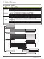
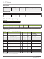
&RQILJXUDWLRQRIPRQLWRUHGSDUDPHWHUV
It is possible to select up to 4 parameters to display their values in the [1.2 - MONITORING] menu on the graphic display terminal.
The selection is made via the [6 - MONITORING CONFIG.] menu, [6.3 - COM. MAP CONFIG.] submenu.
Each parameter in the range [Address 1 select.] … [Address 4 select.]
is used to select the parameter logic address. Select an address of zero
to disable the function.
In the example given here, the monitored words are:
• Parameter 1 = Motor current (LCR): logic address 3204;
signed decimal format.
• Parameter 2 = Motor torque (OTR): logic address 3205;
signed decimal format.
• Parameter 3 = Last fault occurred (LFT): logic address 7121;
hexadecimal format.
• Disabled parameter: address 0; default format: hexadecimal format.
RDY
NET
+0.00Hz
0A
6.3 COM. MAP CONFIG.
Word 1 add. select.
:
3204
Format word 1
:
Signed
Word 2 add. select.
:
3205
Format word 2
:
Signed
Word 3 add. select.
:
7121
Code
Quick
Format word 33
:
Hex
Word 4 add. select.
Format word 4
:
:
0
Hex
One of the three display formats below can be assigned to each monitored word:
)RUPDW
Hexadecimal
Signed decimal
Unsigned decimal
28
5DQJH
0000 … FFFF
-32,767 … 32,767
0 … 65,535
7HUPLQDOGLVSOD\
[Hex]
[Signed]
[Unsigned]
HRB10065 02/2013
efesotomasyon.com
6WDQGDUG:HEVHUYHU
:HEVHUYHUIXQFWLRQ
0HQX
HOME
3DJH
English
Drive monitor
Drive parameters
)XQFWLRQ
Home page
Display of the main drive parameters (motor speed, state of drive logic and analog I/O, status)
Display and modification (password-protected) of the drive parameters, arranged by category
MONITORING
Display of two drive parameters (speed, voltage, etc.) in the form of an oscilloscope type
Drive chart
time chart
Ethernet
Display and resetting of the communication statistics
Modbus TCP
Display and resetting of the Modbus TCP communication statistics
DIAGNOSTICS
Ethernet/IP
Display and resetting of the etherNET/IP communication statistics
RSTP port
Display and resetting of the RSTP ports communication statistics
RSTP bridge
Display and resetting of the RSTP bridge communication statistics
Network & protocol Changing the protocol and the communication settings
RSTP
Changing the bridge and port settings for RSTP function
Modbus TCP
Changing the assignment of the Modbus TCP IO Scanning periodic variables
scanner
SETUP
EtherNET/IP
Changing the assignment of the EtherNET/IP IO Scanning periodic variables
scanner
FDR Agent
Managment of the FDR agent of th communication card
Email
Changing the Email alert function settings
Security
Changing the username and password for monitoring and write access
DOCUMENTATION
References
Link to the site http://www.schneider-electric.com
³+RPH´PHQXSDJH32
³0RQLWRULQJ´PHQXSDJH32
“Drive monitor” page 33
“Drive parameters” page 34
“Drive chart” page 35
³'LDJQRVWLFV´PHQXSDJH36
“Ethernet” page 36
“Modbus TCP” page 36
“EtherNET/IP” page 37
“RSTP port” page 37
“RSTP bridge” page 38
³6HWXS´PHQXSDJH39
“Network & protocol” page 39
“RSTP” page 40
“Modbus TCP scanner” page 43
“EtherNET/IP scanner” page 43
“FDR agent” page 43
“Email” page 44
³6HFXULW\´VXEPHQX45
“Monitor password” page 45
“Data write password” page 45
³'RFXPHQWDWLRQ´PHQX46
“Administrator password”
www.schneider-electric-com
HRB10065 02/2013
29
efesotomasyon.com
6WDQGDUG:HEVHUYHU
$SSOHWV
The Web server downloads Java programs called “applets” to your computer. These applets communicate with the drive using Modbus
services (on port 502), thus establishing one or more connections between the computer and the drive. Until an applet has been fully
transmitted from the drive to the browser, a gray rectangle appears in the place reserved for it in the page.
The applet connects when the page is opened and remains connected until the page is closed.
Display problems can appear with the internet Explore default JVM. Use the SUN Java virtual machine V1.6.
The applets associated with the Web pages monitor communication with the drive. When the drive no longer responds to requests to update
the data, the message “Link down” is displayed in one field and all the other field contents are emptied.
Subsequently, the description of each page indicates the data refresh period requested by the applet loaded on the computer. The refresh
period actually observed depends on:
• The performance of the computer on which the Web browser is running.
• The communication system response time.
• The amount of data to be refreshed on the page.
30
HRB10065 02/2013
efesotomasyon.com
6WDQGDUG:HEVHUYHU
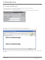
$FFHVVWRWKH:HEVHUYHU
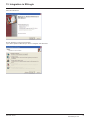
To connect to the Web server of a drive located, for example, at IP address 139.160.69.241 enter the URL
³KWWS´ in the address bar of a Web browser.
When the browser first connects to the drive Web server, it requests entry of a user name and a password (HTTP password).
By default, the user name and the password (HTTP password) are both “USER” (upper case).
If authentication is accepted, the home page is displayed. If not, after three failed attempts, access to this page is denied:
To attempt a new connection to the drive server home page, simply refresh the Web browser display (F5 key or “Refresh” button,
for example).
HRB10065 02/2013
31
efesotomasyon.com
6WDQGDUG:HEVHUYHU
:HEVHUYHUXVHULQWHUIDFH
All the drive Web server pages have the same appearance:
A bar at the top containing links to HTML pages for the main menus: “Home”, “Documentation”, “Monitoring, ”setup“, etc.
This bar is the same regardless of which HTML page is being viewed.
1RWH The “Control” and “Maintenance” menus are inoperative and grayed-out. They only appear because of the “Transparent Ready”
common interface.
A menu down the left-hand side which displays links to the HTML pages available in the selected menu.
The center part of the window displays the information for the selected page.
³+RPH´PHQX
The home page or “Home” menu contain the following items:
• A “Languages” submenu containing:
- A link to the “English”
The only link in the “Languages” submenu sends the user to the home page in English and configures the Web browser to open the HTML
pages located in the corresponding directory (e.g., the “http://139.160.69.241/html/english/” directory becomes the standard directory in the
case of English).
0RQLWRULQJPHQX
The “Monitoring” menu contains the following items:
• A link to the “Drive monitor” page.
• A link to the “Drive parameters” page.
• A link to the “Drive chart” page.
32
HRB10065 02/2013
efesotomasyon.com
6WDQGDUG:HEVHUYHU
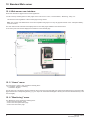
b'ULYHPRQLWRUSDJH
This page gives an overview of the drive state.
The state indicated in the “Altivar State” field corresponds to the display on the drive integrated display terminal. A delay may sometimes
be noticed between the displays on the Web server and the display terminal, depending on the performance of the computer used to display
the pages using a Web browser and the communication system performance.
The motor speed displayed on the “Motor Speed” gauge is calibrated according to the maximum frequency [Max frequency] (tFr)
and the number of pairs of poles [Pr] (PPn).
The LI… area gives the state of the drive terminals (logic inputs LI1 to LI14, logic outputs LO1 to LO4, relay outputs R1 to R4, analog inputs
AI1 to AI4 and analog outputs AO1 to AO3). When a logic input is active, the LED is green. When a logic output is active, the LED is red.
HRB10065 02/2013
33
efesotomasyon.com
6WDQGDUG:HEVHUYHU
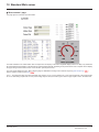
b³'ULYHSDUDPHWHUV´SDJH
This page is used to display the drive parameters and modify their values.
The parameters are arranged in groups, and consistent with the keypad and user manuals
The display mode for each value depends on the nature of the parameter.
• The unit for the physical values is displayed in the "Unit" column.
• The registers (bit fields) are displayed in hexadecimal format (16#xxxx).
• Signed values are displayed as such.
To begin the monitoring, click the "Start animation" button :
To modify the parameter value, click the "Write value of selected row" button then select the parameter to modify
It is only possible to modify the parameter values after entering the "Write password" (see "Monitor password" and "Data write password
pages" section on page 45). Click on the "Password" button to enter this password. An entry field then appears in the parameter table, and
also a "Cancel" button, for canceling the password entry. After entering the password, press the Enter key so that it is taken into account
by the Web browser.
When the value of a parameter cannot be modified, a warning appears : "This parameter can't be written !"
This is the case for all parameters until you have correctly entered the Password.
If IO Scanning has been enabled, modifying the value of a parameter assigned to periodic output variables will have no effect since this
value is updated cyclically by the PLC. The same applies if a parameter is written periodically by a Modbus service.
34
HRB10065 02/2013
efesotomasyon.com
6WDQGDUG:HEVHUYHU
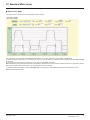
b³'ULYH&KDUW´SDJH
This page is used to see how two drive parameters evolve over time.
Two parameters can be selected and displayed simultaneously. To do this, select them in the 7UDFH and 7UDFH list.
To define the display range better, you can modify the curve min and max points by entering the values directly in the fields: 0LQ and 0D[
of each trace.
In order to speed up sampling, it is possible to put the value 0 in the ,QWYV entry field.
1RWH Entering the value 0 increases the traffic on the Ethernet network and can cause collision problems if there is too much traffic, thereby
reducing the overall network performance. The sampling period can be increased.
To start the oscilloscope function, press the 5XQ6WRS button. Pressing the button again halts sampling and updates the screen.
5HVHW clears the active traces.
HRB10065 02/2013
35
efesotomasyon.com
6WDQGDUG:HE6HUYHU
'LDJQRVWLFV
The “Diagnostics” menu contains the following item:
•
•
•
•
•
A link to the “Ethernet” page.
A link to the “Modbus TCP” page.
A link to the “EtherNET/IP” page.
A link to the “RSTP port” page.
A link to the “RSTP bridge” page.
b³(WKHUQHW´SDJH
This page provides the Ethernet statistics.
b³0RGEXV7&3´SDJH
Reserved for Modbus parameters. See ATV61/71 ModbusTCP manual HRB10064 to the website www.schneider-electric.com
36
HRB10065 02/2013
efesotomasyon.com
6WDQGDUG:HEVHUYHU
b³(WKHU1(7,3´SDJH
b³5673SRUW´SDJH
HRB10065 02/2013
37
efesotomasyon.com
6WDQGDUG:HEVHUYHU
b³5673EULGJH´SDJH
38
HRB10065 02/2013
efesotomasyon.com
6WDQGDUG:HEVHUYHU
³6HWXS´PHQX
The “Setup” menu contains the following items:
• A link to the "Network & protocol" page
• A link to the "RSTP" page.
• A link to the "Modbus TCP scanner" page.
• A link to the "EtherNET/IP scanner" page.
• A link to the "FDR Agent" page.
• A link to the "Email" page.
• A “Security” submenu containing:
- A link to the ”Monitor password” page.
- A link to the ”Data write password” page.
- A link to the ”Administrator Password” page.
b³1HWZRUNSURWRFRO´SDJH
HRB10065 02/2013
39
efesotomasyon.com
6WDQGDUG:HEVHUYHU
b³5673´SDJH
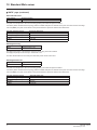
%ULGJHSDUDPHWHUV
6WDWXV
/RJLFDGGUHVV
60700
6XSSRUWHGYDOXHV
0 (disabled)
1 (Enabled)
Enable the use of Rapid Spanning-Tree Protocol
%ULGJHSULRULW\
/RJLFDGGUHVV
60701
6XSSRUWHGYDOXHV
0
4096
8192
12288
16384
20480
24576
28672
32768
36864
40960
45056
49152
53248
57344
61440
The bridge priority is used to control which bridge is elected as the root bridge.
Bridge with the smallest (lowest) bridge ID is elected as the root bridge. Bridge ID consists of the configurable priority and the MAC address
of the bridge. To compare two bridge IDs, the priority is compared first. If the bridge priorities are equal, then the MAC addresses are
compared.
The bridge priority can be set only in increments of 4096.
+HOORWLPH
/RJLFDGGUHVV
60702
6XSSRUWHGYDOXHV
1 to 10 seconds
The hello time parameter corresponds to the time interval at which the root bridge transmits configuration Bridge Protocol Data Units
(BPDU)s.
40
HRB10065 02/2013
efesotomasyon.com
6WDQGDUG:HEVHUYHU
b³5673´SDJHFRQWLQXHG
5673%ULGJH0D[$JH7LPH
/RJLFDGUHVV
60703
6XSSRUWHGYDOXHV
6 to 40 seconds
The maximum age time correspond to the maximum expected arrival time of hello BPDUs. If the timer expires, the bridge detects a
communication interruption to the root bridge and initiates a topology convergence.
The maximum age timer should be longer than the configured Hello Timer.
7UDQVPLW&RXQW
/RJLFDGUHVV
60704
6XSSRUWHGYDOXHV
3 to 100
It defines the maximum number of BPDUs the system can transmit on a port within the Hello Time interval.
)RUZDUGGHOD\
/RJLFDGUHVV
60705
6XSSRUWHGYDOXHV
4 to 30 seconds
The forward delay time corresponds to the amount of time an STP bridge port remains in the listening and learning states before
transitioning to the forwarding state.
In case of a too short interval, unnecessary spanning-tree convergences may occur.
3RUWVSDUDPHWHUV
3RUW/HIW3ULRULW\
/RJLFDGUHVV
60724
6XSSRUWHGYDOXHV
0 to 240 (in step of 16)
This defines the priority of the interface compare to other going to the same subnet.
The left port priority can be set only in increments of 16.
The value will be taken into account by the drive after power off and on the drive.
HRB10065 02/2013
41
efesotomasyon.com
6WDQGDUG:HEVHUYHU
b³5673´SDJHFRQWLQXHG
3RUW/HIW3DWK&RVW
/RJLFDGUHVV
60725
6XSSRUWHGYDOXHV
0 (Auto) to 200,000,000
The path cost corresponds to the cost of sending spanning tree traffic through the interface.
It is used by RSTP to determine the topology with the smallest total path cost between each point of the tree and the root bridge
If set to $XWR: the path cost is based on the port link maximum speed as defined in the table below
3RUWOLQNPD[LPXPVSHHG
10 Gb/s (Not supported by the card)
1 Gb/S (Not supported by the card)
100 Mb/s
10 Mb/s
$XWRPDWLF3DWK&RVW
2,000
20,000
200,000
2,000,000
3RUW5LJKW3ULRULW\
/RJLFDGUHVV
60738
6XSSRUWHGYDOXHV
0 to 240 (in step of 16)
This defines the priority of the interface compare to other going to the same subnet.
TheRight port priority can be set only in increments of 16.
The value will be taken into account by the drive after power off and on the drive.
3RUW5LJKW3DWK&RVW
/RJLFDGUHVV
60739
6XSSRUWHGYDOXHV
0 (Auto) to 200,000,000
The path cost corresponds to the cost of sending spanning tree traffic through the interface.
It is used by RSTP to determine the topology with the smallest total path cost between each point of the tree and the root bridge
If set to $XWR: the path cost is based on the port link maximum speed as defined in the table below
3RUWOLQNPD[LPXPVSHHG
10 Gb/s (Not supported by the card)
1 Gb/S (Not supported by the card)
100 Mb/s
10 Mb/s
42
$XWRPDWLF3DWK&RVW
2,000
20,000
200,000
2,000,000
HRB10065 02/2013
efesotomasyon.com
6WDQGDUG:HEVHUYHU
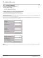
b³0RGEXV7&3VFDQQHU´SDJH
See ATV61/71 ModbusTCP manual HRB10064 to the website www.schneider-electric.com
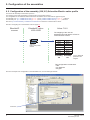
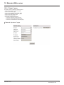
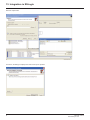
b³(WKHU1(7,3VFDQQHU´SDJH
EtherNet/IP scanner setup
All modifications are protected by the “Write password” modification password. Click on the “PassWord” button to enter the
“Write password”. After correctly entering the password, you can access “IoScanner”, ,“Setpoint unit”, “Output parameters”,
“Input parameters” and the “Save” and “Abort” buttons.
By default, the password is “USER”. It can be modified in the “Data write password” page.
b³)'5$JHQW´SDJH
Reserved for Modbus parameters. (See ATV61/71 ModbusTCP manual HRB10064)12.
HRB10065 02/2013
43
efesotomasyon.com
6WDQGDUG:HEVHUYHU
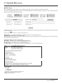
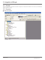
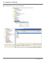
b(PDLOSDJH
The configuration page of the Email service is available in the setup menu V Email of the option board web page
This service is able to generate and send emails to a predefined address in case of alarm warning or drive fault. The controller inside option
board can also initiate the sending of an email.
It is possible to configure the Email service after entering the "Write password" (see "Monitoring password" and "Data write password pages"
section on page 45).
Enter the following information to configure the Email service :
(PDLO,36HUYHU IP address of the Email server that will process the message (SMTP server)
(PDLO'HVW# Email address of the Email recipient
(PDLO)URP# Email address of the Ethernet option board which will send the email (this is a virtual address since the option board does
not provide any incoming email box)
Configure the triggering mode for sending Email :
'ULYH)DXOW an Email is sent on a drive fault (triggered by ETA.3)
'ULYHDODUP an Email is sent on a drive warning (triggered by ETA.7)
(WK%RDUGIDXOW an Email is sent on an ethernet board fault
3/&%RDUGVWDWXV an Email is sent on demand from the application of the controller inside board
Email example sent on CNF fault of the Ethernet board :
)URP
$/7,9$5#VFKQHLGHUHOHFWULFIU
6XEMHFW
(UURU&1)RQ$OWLYDU'ULYH
'DWH
'HF
)DXOWRFFXUHGRQ(WKHUQHW%RDUG
V'ULYH
'HYLFH1DPH$79
,3$GGUHVV
5HIHUHQFH$79+0
'HVFULSWLRQ
/)55HJLVWHU ;;
7LPH2XW7&30RGEXV&1)
,03257$17127,&(
7KLV(PDLOKDVEHHQDXWRPDWLFDOO\JHQHUDWHG3OHDVHGRQRWUHSO\
&RS\ULJKW6FKQHLGHU(OHFWULF$OOULJKWVUHVHUYHG
Service diagnostic :
• Email Status
- 0 V Idle
- 1 V Operational
- 2 V Stopped
• SentCount : number of emails successfully sent
• ErrorCount : number of errors occurred
LastError : last error code
44
HRB10065 02/2013
efesotomasyon.com
6WDQGDUG:HEVHUYHU
³6HFXULW\´6XEPHQX
The “Security" submenu contains the following items:
• A “Security” submenu containing:
- A link to the ”Monitor password” page.
- A link to the ”Data write password” page.
- A link to the ”Administrator Password” page.
b³0RQLWRUSDVVZRUG´DQG³'DWDZULWHSDVVZRUGSDJHV´
These two pages are used to modify the two Web server passwords.
By default, the user name and both passwords are: “USER” (upper case).
The Monitor security password is the basic level access to the drive through the webserver: it allows the access to the different web pages
but don’t authorize write access.
New level username and password can be redefined here.
When the value of a parameter cannot be modified, the background of the corresponding cell appears grayed-out. This is the case for all
parameters until you have correctly entered the “Write password”.
1RWHDo not lose the user name or the passwords. If they are lost, the Web server can no longer be used, and the card has to be sent
for repair.
HRB10065 02/2013
45
efesotomasyon.com
6WDQGDUG:HEVHUYHU
³'RFXPHQWDWLRQ´PHQX
The “Documentation” menu contains a link to the “References” page.
This page displays a link to the site: http://www.schneider-electric.com/.
46
HRB10065 02/2013
efesotomasyon.com
,QWHJUDWLRQLQ56/RJL[
3ULQFLSOH
RSX drive equipped with an EtherNet/IP card shall be configured as a "Generic Ethernet Module" in the same way as the EtherNet/IP
adapter of PowerFlex 70 drives.
3URFHGXUH
b&UHDWHDQHZSURMHFW
HRB10065 02/2013
47
efesotomasyon.com
,QWHJUDWLRQLQ56/RJL[
b$GGD(WKHU1HW,3VFDQQHUWRWKH,2FRQILJXUDWLRQ
48
HRB10065 02/2013
efesotomasyon.com
,QWHJUDWLRQLQ56/RJL[
HRB10065 02/2013
49
efesotomasyon.com
,QWHJUDWLRQLQ56/RJL[
b&RQILJXUHWKH(WKHU1HW,3VFDQQHU
b$GGD(WKHU1HW,3$79GULYHWRWKH,2FRQILJXUDWLRQ
50
HRB10065 02/2013
efesotomasyon.com
,QWHJUDWLRQLQ56/RJL[
HRB10065 02/2013
51
efesotomasyon.com
,QWHJUDWLRQLQ56/RJL[
b&RQILJXUHWKH$79(WKHU1HW,3FDUG
Above the Allen-Bradley drive profile is selected.
52
HRB10065 02/2013
efesotomasyon.com
,QWHJUDWLRQLQ56/RJL[
Below the CIP extended speed control profile is selected.
Below the CIP extended speed and torque control profile is selected.
HRB10065 02/2013
53
efesotomasyon.com
,QWHJUDWLRQLQ56/RJL[
Below native RSX profile is selected.
5HJLVWHULQJWKH('6ILOHLQ56ORJL[
An EDS file is provided with the drive. (This file is available on the CD or on www.schneider-electric.com).
It exists 1 EDS file for the ATV71 and 1 EDS file for the ATV61.
The following lines describe how to import these files in your project:
In RSnetWorx , start the EDS wizards
54
HRB10065 02/2013
efesotomasyon.com
,QWHJUDWLRQLQ56/RJL[
Follow the instructions:
Choose "Register" to import a new EDS file.
If you want to update an EDS file you need to "unregister" this device first.
HRB10065 02/2013
55
efesotomasyon.com
,QWHJUDWLRQLQ56/RJL[
Select the required file:
Then finish, the dialog box displays the result of the import operation.
56
HRB10065 02/2013
efesotomasyon.com
&,3REMHFWV
6XSSRUWHGREMHFWFODVVHV
Three categories of object classes can be defined:
• 1: CIP device on EtherNet/IP.
• 2: AC/DC drive.
• 3: VSD specific.
These objects are detailed here:
16#01
16#02
16#F6
16#F5
16#05
1
1
1
1
1
1XPEHURI
LQVWDQFHV
1
1
1
1
1
16#28
16#29
2
2
1
1
Defines data for the motor connected to the device
Manages drive functions, operational states and control
16#2A
16#04
2
2
3
1
12
1
Provides drive configuration
Defines I/O data format
Vendor specific - drive's parameters
2EMHFWFODVV
&ODVV,'
Identity object (14. 2.) page 57
Message router object (14. 3.) page 61
Ethernet Link object (14. 4.) page 63
TCP/IP Interface object (14. 5.) page 66
Connection object manager (14. 6.)
page 68
Motor data object (14. 7.) page 69
Control supervisor object (14. 8.) page
70
AC/DC Drive Object (14. 9.) page 72
Assembly object (14. 10.) page 73
Application objects (14. 11.) page 74
&DW
(IIHFWRQEHKDYLRU,QWHUIDFH
Supports the reset service
Explicit message connection
Counter and status information
TCP/IP configuration
,GHQWLW\REMHFW
The Identity object provides identification and status information about the drive.
&ODVVFRGH
+H[DGHFLPDO
16#01
'HFLPDO
1
&ODVVDWWULEXWHV
$WWULEXWH,'
$FFHVV
1DPH
'DWDW\SH
9DOXH
'HWDLOV
1
Get
Revision
UINT
1
-
2
Get
Max Instances
UINT
1
1 defined instance
3
Get
Number of Instances
UINT
4
Get
Optional attribute list
UINT
1
-
6
Get
Max ID of class attributes
UINT
7
-
7
Get
Max ID of instance
attribute
UINT
17
-
-
HRB10065 02/2013
57
efesotomasyon.com
&,3REMHFWV
,QVWDQFHDWWULEXWHV
$WWULEXWH,'
$FFHVV 1DPH
1HHG 'DWDW\SH
9DOXH
'HWDLOV
1
Get
Vendor ID
Req.
UINT
243
Schneider Automation, Inc [243]
2
Get
Device type
Req.
UINT
16#02 AC/DC drive profile
3
Get
Product code
Req.
UINT
5 or 7
5: ATV71
7: ATV61
4
Get
Revision
Req.
Struct of:
USINT
USINT
—
Product revision of the drive (1)
5
Get
Status
Req.
WORD
—
See definition in the table below (Attribute 5-Status)
6
Get
Serial number
Req.
UDINT
—
Serial number of the drive
7
Get
Product name
Req.
Struct of:
USINT
STRING
—
11 (product name length)
“ATV71 Drive”
8
Get
State
Opt.
USINT
—
0: Non existent
1: Device self-testing
2: Standby
3: Operational
4: Major recoverable fault
5: Major unrecoverable fault
10
Get/Set
Heartbeat interval (2)
Opt.
USINT
0–255 Interval in seconds between two heartbeat messages.
0: No message.
(1) Mapped in a word: MSB minor revision (second USINT), LSB major revision (first USINT).
Example: 517 = 16#0205 means revision V5.2.
(2) The heartbeat message broadcasts the current state of the device.
$WWULEXWH6WDWXV
%LW
'HILQLWLRQ
+RZ
0
Owned by Master (predefined Master/Slave
Connection)
No interface
2
Configured
If any of the product (option + drive) NVS attributes has changed
from their default (out of box values)
127( Network comm attributes are not included here.
4-7
Extended device status: See table (Bit4-7
Defenition) page 59
-
8
Minor Recoverable Fault
No minor rec. fault
9
Minor Unrecoverable Fault
No minor unrec. fault
10
Major Recoverable Fault
CnF detected error or CIP connection timeout or Eth network
overload
11
Major Unrecoverable Fault
ILF detected fault, eeprom failed, OB hardware detected error
Others
Reserved 0
-
58
HRB10065 02/2013
efesotomasyon.com
&,3REMHFWV
%LW'HILQLWLRQ
%LW
'HILQLWLRQ
+RZ
0000
Self testing or unknown
Not used
0001
Firmware update in progress
Not used
0010
At least on faulted I/O connection
-
0011
No I/O connections established
-
0100
Non-volatile configuration bad
Non volatile memory detected error in OB
0101
Major fault - either bit 10 or 11 is true
Bit 10 or 11 is true
0110
At least one I/O connection in run mode
-
0111
At least one I/O connection established, all in idle mode -
1000
1001
Reserved, shall be 0
-
1 0 1 0 to
1111
Vendor specific
-
6XSSRUWHG&ODVV6HUYLFHV
6HUYLFHFRGH
6HUYLFH1DPH
'HVFULSWLRQ
01 hex
Get_Attribute_All
Read all attributes
0E hex
Get_Attribute_Single
Read one attributes
6XSSRUWHG,QVWDQFH6HUYLFHV
6HUYLFHFRGH
6HUYLFH1DPH
'HVFULSWLRQ
01 hex
Get_Attribute_All
Read all attributes
0E hex
Get_Attribute_Single
Read one attributes
10 hex
Set_Attribute_Single
Write one attribute
05 hex
Reset
Perform the reset of the drive
HRB10065 02/2013
59
efesotomasyon.com
&,3REMHFWV
6WDWH'LDJUDPIRUWKH,GHQWLW\2EMHFW
1RQH[LVWHQW
Power loss
(from any state)
Off
Power
Applied
Identity object reset service
'HYLFHVHOIWHVWLQJ
(from any state except Major
unrecoverable fault)
Failed
tests
Flashing red/green
Passed
tests
Fault corrected
6WDQGE\
Flashing green
Activated
Desactivated
Minor
fault
2SHUDWLRQDO
Solid green
Major
recoverable
fault
0DMRU
UHFRYHUDEOH
IDXOW
0DMRU
XQUHFRYHUDEOH
IDXOW
Flashing red
60
Major
unrecoverable
fault
Solid red
HRB10065 02/2013
efesotomasyon.com
&,3REMHFWV
0HVVDJHURXWHUREMHFW
The Message router object is the element through which all the "Explicit messages" objects pass in order to be directed towards the objects
they are truly destined to.
&ODVVFRGH
+H[DGHFLPDO
16#02
'HFLPDO
2
&ODVVDWWULEXWHV
$WWULEXWH,'
$FFHVV
1DPH
1HHG
'DWDW\SH
9DOXH
'HWDLOV
1
Get
Revision
Opt.
UINT
1
-
2
Get
Max instances
Opt.
UNT
1
1 Defined instance
HRB10065 02/2013
61
efesotomasyon.com
&,3REMHFWV
,QVWDQFHDWWULEXWHV
$WWULEXWH,'
$FFHVV 1DPH
1HHG 'DWDW\SH
9DOXH
'HWDLOV
1
Get
Object list:
Number classes
Opt.
Struct of:
UINT
UINT [ ]
20
(codes)
List of supported objects; the first UINT is the number of
supported classes; the remaining UINTs are the codes of
these classes.
2
Get
Number available
Opt.
UINT
1
Maximum number of simultaneous connections
3
Get
Number active
Opt.
UINT
1
Number of active connections
4
Get
Active connections Opt.
UINT [ ]
1
List of active connections (referred to with their respective
Connection instance ID)
&ODVVVHUYLFH
6HUYLFHFRGH
6HUYLFHQDPH
1HHG
'HVFULSWLRQ
16#0E
Get_Attribute_Single
Req.
Read an attribute
6HUYLFHFRGH
6HUYLFHQDPH
1HHG
'HVFULSWLRQ
16#0E
Get_Attribute_Single
Req.
Read an attribute
,QVWDQFHVHUYLFH
62
HRB10065 02/2013
efesotomasyon.com
&,3REMHFWV
(WKHUQHW/LQNREMHFW
This object provides the mechanism to configure a device's TCP/IP network interface.
b&ODVVFRGH
+H[DGHFLPDO
16#F5
GHFLPDO
245
b&ODVVDWWULEXWHV
Class attributes for this object are optional.
b,QVWDQFHDWWULEXWHV
$WWULEXWH,'
1
$FFHVV
Get
1DPH
6WDWXV
QHHG
Req.
'DWDW\SH
DWORD
9DOXH
Bit level
2
Get
&RQILJXUDWLRQ
FDSDELOLW\
Req.
DWORD
'HWDLOV
The interface configuration attribute has not
been configured.
1 The interface configuration contains a valid
configuration.
2-15 Reserved for future use.
BOOTP Client.
0
DNS Client.
DHCP Client.
Bit level
DHCP-DNS capable.
Interface configuration settable.
All other bits are reserved and shall be set to 0.
3
Get
&RQILJXUDWLRQ
Req.
DWORD
The interface configuration is valid.
Set
FRQWURO
The interface configuration must be
obtained with BOOTP.
The interface configuration must be
Bit level
obtained with DHCP..
Reserved.
127( : 7KLVDWWULEXWHLQWHUDFWVZLWKWKH$OWLYDUSDUDPHWHU
DNS Enable.
>,3PRGH@VHHFKDSWHU9. All other bits are reserved and shall be set to 0.
4
Get
3K\VLFDOOLQN
Req.
STRUCT {
3DWKVL]H: number of 16 bit words in the element
UINT SDWKVL]H
Path
Padded EPATH SDWK
3DWK: Logical segments identifying the physical
}
link object. The path is restricted to one logical
class segment and one logical instance segment.
The maximum size is 12 bytes.
HRB10065 02/2013
63
efesotomasyon.com
&,3REMHFWV
$WWULEXWH,'
5
$FFHVV
Get
Set
1DPH
,QWHUIDFH
FRQILJXUDWLRQ
QHHG
Req.
'DWDW\SH
STRUCT {
9DOXH
UDINT ,3$GGUHVV
'HWDLOV
,3$GGUHVV Value of 0 indicates noIP address has
been configured. Otherwise, the IP address shall be
set to a valid Class A, B, or C address and shall not
be set to the loopback address (127.0.0.1).
UDINT 1HWZRUN0DVN
1HWZRUN0DVNValue of 0 indicates no network
UDINT *DWHZD\DGGUHVV mask address has been configured.
UDINT 3ULPDU\1DPH
server
*DWHZD\$GGUHVV Value of 0 indicates no IP
address has been configured. Otherwise, the IP
address shall be set to a valid Class A, B, or C
UDINT 6HFRQGDU\QDPH address and shall not be set to the loopback
server
address (127.0.0.1).
STRING 'HIDXOW'RPDLQ 3ULPDU\QDPH Value of 0 indicates no name
QDPH
server address has been configured. Otherwise, the
name server address shall be set to a valid Class A,
}
B, or C address.
6HFRQGDU\1DPH Value of 0 indicates no
secondary name server address has been
configured. Otherwise, the name server address
shall be set to a valid Class A, B, or C address.
6
Get
Set
+RVW1DPH
Req.
'HIDXOWGRPDLQQDPH ASCII characters.
Maximum length is 48 characters. Shall be padded
to an even number of characters (pad not included
in length). A length of 0 shall indicate no Domain
Name is configured.
ASCII characters. Maximum length is
64 characters. Shall be padded to an even number
of characters (pad not included in length). A length
of 0 shall indicate no Host Name is configured.
STRING
b&ODVVVHUYLFH
6HUYLFH&RGH
16#01
6HUYLFH1DPH
Get_Attribute_All
1HHG
Optional
16#0E
Get_Attribute_Single
Optional
6HUYLFH&RGH
16#01
6HUYLFH1DPH
Get_Attribute_All
1HHG
Optional
16#0E
16#02
16#10
Get_Attribute_Single
Set_Attribute_All
Set_Attribute_Single
Required
optional
Required
'HVFULSWLRQ
Returns a predefined listing of this objects
attributes.
Returns the contents of the specified attribute.
b,QVWDQFHVHUYLFH
64
'HVFULSWLRQ
Returns a predefined listing of this objects
attributes.
Returns the contents of the specified attribute.
Modifies all settable attributes.
Modifies a single attribute.
HRB10065 02/2013
efesotomasyon.com
&,3REMHFWV
b%HKDYLRXU
The following state machine is used to configure the TCP/IP network interface.
Non-existent
Powerup/Reset
Status = 0x00000000
BOOTP/DHCP
Disabled AND Stored
Config is Valid
Obtaining initial
Configuration
BOOTP OR
DHCP Enabled
BOOTP/DHCP Disabled AND
Stored Config is Invalid
Waiting for Configuration
BOOTP/DHCP
Response Received
Set_Attributes
Request Received
Status = 0x00000000
Applying Configuration
Configuration Applied
Change Interface
Configuration
TCP/IP Network
Interface Configured
(Status = 0x00000001)
HRB10065 02/2013
65
efesotomasyon.com
&,3REMHFWV
7&3,3,QWHUIDFHREMHFW
This object maintains link specific counters and status information for an Ethernet 802.3 communications interface.
b&ODVVFRGH
+H[DGHFLPDO
16#F6
'HFLPDO
246
b&ODVVDWWULEXWHV
$WWULEXWH,'
1
2 through 7
$FFHVV
Get
1DPH
Revision
1HHG
Req.
optional
'DWDW\SH
UINT
9DOXH
2
b,QVWDQFHDWWULEXWHV
$WWULEXWH,'
1
$FFHVV
Get
1DPH
1HHG
,QWHUIDFH6SHHG Req.
'DWDW\SH
UDINT
9DOXH
'HWDLOV
0,10,100 Speed in Mbps.
1000, etc.
Link status
Half/full duplex
Negotiation status
Bit
level
Manual setting / requires reset
Local Hardware fault
All other bits are reserved and shall be set to 0.
This array contains the MAC address of the
card.Format: XX-XX-XX-XX-XX-XX
2
Get
,QWHUIDFHIODJV
Req.
DWORD
3
Get
3K\VLFDO
$GGUHVV
Req.
ARRAY OF
6 USINTs
4…
Get
Interface
counters
Cond.
STRUCT {
UDINT In Octets
UDINT In Ucast Packets
UDINT In NUcast
Packets
UDINT In Discards
UDINT In Errors
UDINT In Unknown
Protos
UDINT Out Octets
UDINT Out Ucast
packest
UDINT Out NUcast
Packets
UDINT Out discards
UDINT
}
66
Octets received on the interface
Unicast Packets received on the interface.
Non Unicast Packets received on the interface.
Inbound packets received on the interface but
discarded.
Inbound packets that contain errors. (does not
include in Discards)
Inbound packets with unknown protocol.
Octets sent on the interface.
Unicast Packets sent on the interface.
Non Unicast Packets sent on the interface.
Outbound packets discarded
Outbound packets that contain errors
HRB10065 02/2013
efesotomasyon.com
&,3REMHFWV
$WWULEXWH,'
5
$FFHVV
Get
1DPH
1HHG
Media Counters Cond.
6
Set
Interface control Optional
'DWDW\SH
9DOXH 'HWDLOV
STRUCT {
UDINT Alignment errors
Frames received that are not an integral
number of octets in length
UDINT FCS Errors
Frames received that do not pass the FCS
check
UDINT Single collisions
Successfully transmitted frames which
experienced exactly one collision
UDINT Multiple Collisions
Successfully transmitted frames which
experienced more than one collision
UDINT SQE Test Errors
Number of times SQE test error message is
generated
UDINT Deferred
Frames for which first transmission attempt
Transmissions
is delayed because the medium is busy
UDINT Late Collisions
Number of times a collision is detected later
than 512 bittimes into the transmission of a
packet
UDINT Excessive Collisions
Frames for which transmission fails due to
excessive collision
UDINT MAC Transmit errors
Frames for which transmission fails due to
an internal MAC sublayer transmit error
UDINT Carrier sense Errors
Times that the carrier sense condition was
lost or never asserted when attempting to
transmit a frame
UDINT Frame too long
Frames received that exceed the maximum
permitted frame size
UDINT MAC Receive Errors
Frames for which reception on an interface
fails due to an internal MAC sublayer
receive error
}
STRUCT {
WORD Control Bits
Interface control bits
UINT Force interface
Speed at which the interface shall be forced
Speed
to operate.
}
HRB10065 02/2013
67
efesotomasyon.com
&,3REMHFWV
b&ODVVVHUYLFH
6HUYLFH&RGH
16#01
16#0E
16#10
6HUYLFH1DPH
Get_Attribute_All
Get_Attribute_Single
Get_and_clear
1HHG
Optional
Optional
Cond.
'HVFULSWLRQ
Returns a predefined listing of this objects attributes.
Returns the contents of the specified attribute.
Modifies a single attribute
6HUYLFH1DPH
Get_Attribute_All
Get_Attribute_Single
Set_Attribute_Single
1HHG
Optional
Required
Required
'HVFULSWLRQ
Returns a predefined listing of this objects attributes.
Returns the contents of the specified attribute.
Modifies a single attribute.
b,QVWDQFHVHUYLFH
6HUYLFH&RGH
16#01
16#0E
16#10
&RQQHFWLRQREMHFWPDQDJHU
&ODVVFRGH
+H[DGHFLPDO
16#05
'HFLPDO
5
&ODVVDWWULEXWHV
$WWULEXWH,'
$FFHVV
1DPH
1HHG
'DWDW\SH
9DOXH
'HWDLOV
1
Get
Revision
Opt.
UINT
1
—
2
Get
Max instances
Opt.
UINT
4
3 defined instances (1)
(1) Only instances 1 (explicit message), 2 (polled I/O message), and 4 (change of state/cyclic message) are supported. Instance 3 (bit
strobe) is not supported.
$WWULEXWHVRILQVWDQFH²([SOLFLWPHVVDJHLQVWDQFH
$WWULEXWH,'
$FFHVV
1DPH
1HHG
'DWDW\SH
9DOXH
'HWDLOV
1
Get
State
Req.
USINT
—
0 : Non-existent
3 : Established
5 : Deferred Delete
2
Get
Instance_type
Req.
USINT
0
Explicit Message
3
Get
TransportClass_trigger
Req.
BYTE
16#83
Class 3 server
4
Get
Produced_connection_id
Req.
UINT
10xxxxxx011
xxxxxx = Node address
5
Get
Consumed_connection_id
Req.
UINT
10xxxxxx100
xxxxxx = Node address
6
Get
Initial_comm_characteristics
Req.
BYTE
16#21
Explicit messaging via Group 2
7
Get
Produced_connection_size
Req.
UINT
36
Produced data maximum size
(in bytes)
8
Get
Consumed_connection_size
Req.
UINT
36
Consumed data maximum size
(in bytes)
9
Get/Set
Expected_packet_rate
Req.
UINT
2500
2.5 sec. (TimeOut)
12
Get/Set
Watchdog_timeout_action
Req.
USINT
1 or 3
1 : Auto-Delete
3 : Deferred Delete (Default)
13
Get
Produced connection path length
Req.
UINT
0
Length of attribute 14 data
14
Get
Produced connection path
Req.
Array of UINT
Null
Empty
15
Get
Consumed connection path length
Req.
UINT
0
Length of attribute 16 data
16
Get
Consumed connection path
Req.
Array of UINT
Null
Empty
Refer to EtherNet/IP specification for more information.
68
HRB10065 02/2013
efesotomasyon.com
&,3REMHFWV
0RWRUGDWDREMHFW
The Motor data object acts as a motor parameter database.
&ODVVFRGH
+H[DGHFLPDO
16#28
'HFLPDO
40
2EMHFWKH[0RWRU'DWD
3DWK
16#28/01/06 = 40/1/6
16#28/01/07 = 40/1/7
16#28/01/09 = 40/1/9
16#28/01/0F = 40/1/15
&,3QDPH
RatedCurrent
RatedVoltage
RatedFreq
BaseSpeed
&,3FRQILJXUDWLRQSDUDPHWHUQDPH
Motor Rated Cur
Motor Rated Volt
Motor Rated Freq
Motor Base Speed
6FKQHLGHU(OHFWULFDGDSWDWLRQ
3DWK
16#28/01/06 = 40/1/6
16#28/01/07 = 40/1/7
16#28/01/09 = 40/1/9
16#28/01/0F = 40/1/15
&RGH
NCR
UNS
FRS
NSP
$OWLYDUQDPH
Rated mot. current
Rated motor volt.
Rated motor freq.
Rated motor speed
/RJLFDGGUHVV
16#2583 = 9603
16#2581 = 9601
16#2582 = 9602
16#2584 = 9604
&ODVVDWWULEXWHV
$WWULEXWH,'
$FFHVV
1DPH
1HHG
'DWDW\SH
9DOXH
'HWDLOV
1
Get
Revision
Opt.
UINT
2
—
2
Get
Max instance
Opt.
UINT
1
—
6
Get
Max ID number of class attribute
Opt.
UINT
7
—
7
Get
Max ID number of instance attribute
Opt.
UINT
15
—
,QVWDQFHDWWULEXWHV
$WWULEXWH,'
$FFHVV
1DPH
1HHG
'DWDW\SH
9DOXH
'HWDLOV
3
Get/Set
MotorType
Req.
USINT
7
6 = Wound rotor induction motor
7 = Squirrel cage induction motor
6
Get/Set
RatedCurrent
Req.
UINT
Depends on the
drive rating
[Rated mot. current] (nCr)
7
Get/Set
RatedVoltage
Req.
UINT
Depends on the
drive rating
[Rated mot. volt.] (UnS)
9
Get/Set
RatedFreq
Opt.
UINT
50/60
[Rated motor freq.] (FrS)
15
Get/Set
BaseSpeed
Opt.
UINT
Depends on the
drive rating
[Nom motor speed] (nSP)
&ODVVVHUYLFH
6HUYLFHFRGH
6HUYLFHQDPH
1HHG
'HVFULSWLRQ
16#0E
Get_Attribute_Single
Req.
Read an attribute
6HUYLFHFRGH
6HUYLFHQDPH
1HHG
'HVFULSWLRQ
16#0E
Get_Attribute_Single
Req.
Read an attribute
16#10
Set_Attribute_Single
Opt.
Write an attribute
,QVWDQFHVHUYLFH
HRB10065 02/2013
69
efesotomasyon.com
&,3REMHFWV
&RQWUROVXSHUYLVRUREMHFW
The Control supervisor object models the functions for managing all devices within the hierarchy of motor control devices.
2EMHFWKH[&RQWURO6XSHUYLVRU
3DWK
16#29/01/0D = 41/1/13
&,3QDPH
FaultCode
&,3FRQILJXUDWLRQSDUDPHWHUQDPH
Fault Code
6FKQHLGHU(OHFWULFDGDSWDWLRQ
3DWK
16#29/01/0D = 41/1/13
&RGH
ERRD
$OWLYDUQDPH
CiA402 fault code
/RJLFDGGUHVV
16#219E = 8606
&ODVVFRGH
+H[DGHFLPDO
16#29
'HFLPDO
41
&ODVVDWWULEXWHV
$WWULEXWH,'
$FFHVV
1DPH
1HHG
'DWDW\SH
9DOXH
'HWDLOV
1
Get
Revision
Opt.
UINT
2
—
2
Get
Max instance
Opt.
UINT
1
—
6
Get
Max ID number of class attribute
Opt.
UINT
7
—
7
Get
Max ID number of instance attribute
Opt.
UINT
17
—
,QVWDQFHDWWULEXWHV
$WWULEXWH,'
$FFHVV
1DPH
1HHG
'DWDW\SH
'HWDLOV
3
Get/Set
Run Fwd
Req.
BOOL
On an edge (0 V1)
4
Get/Set
Run Rev
Opt.
BOOL
On an edge (0 V1)
5
Get/Set
NetCtrl
Opt.
BOOL
0: Local Control (Channel 1)
1: Network Control (default)
6
Get
State
Opt.
USINT
0 = Vendor Specific,
1 = Startup, 2 = Not_Ready, 3 = Ready,
4 = Enabled, 5 = Stopping,
6 = Fault_Stop, 7 = Faulted
7
Get
Running Fwd
Req.
BOOL
8
Get
Running Rev
Opt.
BOOL
9
Get
Ready
Opt.
BOOL
10
Get
Faulted
Req.
BOOL
12
Get/Set
FaultRst
Req.
BOOL
Fault reset (0 V1)
13
Get
FaultCode
Opt.
UINT
Refer to the Communication parameters manual:
DSP402 fault code (Errd)
15
Get
CtrlFromNet
Opt.
BOOL
0 = Local Control; 1 = Network Control
70
HRB10065 02/2013
efesotomasyon.com
&,3REMHFWV
&ODVVVHUYLFH
6HUYLFH&RGH
6HUYLFHQDPH
1HHG
'HVFULSWLRQ
16#0E
Get_Attribute_Single
Req.
Read an attribute
6HUYLFH&RGH
6HUYLFHQDPH
1HHG
'HVFULSWLRQ
16#0E
Get_Attribute_Single
Req.
Read an attribute
16#10
Set_Attribute_Single
Req.
Write an attribute
16#05
Reset
Req.
Drive reset
,QVWDQFHVHUYLFH
&RQWUROVXSHUYLVRUVWDWHWUDQVLWLRQGLDJUDP
Non-Existent
Switch off
Switch on
Reset
Startup
Fault detected
Main power off
Faulted
Fault Reset
Initialization complete
Fault stop complete
Fault detected
Not_Ready
Main power on
Main power off
Fault_Stop
Fault detected
Ready
Stop complete
Run
Stopping
Stop
Enabled
HRB10065 02/2013
71
efesotomasyon.com
&,3REMHFWV
$&'&'ULYH2EMHFW
The AC/DC Drive object models the functions (such as torque control and speed ramp) that are specific to drives.
&ODVVFRGH
+H[DGHFLPDO
16#2A
'HFLPDO
42
&ODVVDWWULEXWHV
$WWULEXWH,'
$FFHVV
1DPH
1HHG
'DWD7\SH
9DOXH
'HWDLOV
1
Get
Revision
Opt.
UINT
1
—
2
Get
Max instance
Opt.
UINT
1
—
6
Get
Max ID number of class attribute
Opt.
UINT
7
—
7
Get
Max ID number of instance attribute
Opt.
UINT
21
—
,QVWDQFHDWWULEXWHV
$WWULEXWH,'
$FFHVV
1DPH
1HHG
'DWDW\SH
'HWDLOV
3
Get
AtReference
Opt.
BOOL
4
Get/Set
NetRef (1)
Req.
BOOL
0: Local speed setpoint (AI1 or AI2)
1: Speed setpoint via the network
5
Get/Set
NetProc
Opt.
BOOL
Not handled
6
Get/Set
Drive mode
Req.
USINT
1: Open loop
2: Closed loop (FVC)
7
Get
SpeedActual
Req.
INT
Output speed (rFrd)
8
Get/Set
SpeedRef
Req.
INT
Speed setpoint (LFrd)
9
Get
CurrentActual
Opt.
INT
Motor current (LCr)
10
Get/Set
CurrentLimit
Opt.
INT
[Mot. therm. current] (ItH)
11
Get
TorqueActual
Opt.
INT
Output torque (Otrn)
12
Get/Set
TorqueRef
Opt.
INT
Torque setpoint (LtCr)
18
Get/Set
AccelTime
Opt.
UINT
Acceleration time (ACCd)
19
Get/Set
DecelTime
Opt.
UINT
Deceleration time (dECd)
20
Get/Set
LowSpdLimit
Opt.
UINT
Parameter [Low speed] (LSP) converted in RPM
21
Get/Set
HighSpdLimit
Opt.
UINT
Parameter [High speed] (HSP) converted in RPM
&ODVVVHUYLFH
6HUYLFHFRGH
6HUYLFHQDPH
1HHG
'HVFULSWLRQ
16#0E
Get_Attribute_Single
Req.
Read an attribute
6HUYLFHFRGH
6HUYLFHQDPH
1HHG
'HVFULSWLRQ
16#0E
Get_Attribute_Single
Req.
Read an attribute
16#10
Set_Attribute_Single
Opt.
Write an attribute
,QVWDQFHVHUYLFH
72
HRB10065 02/2013
efesotomasyon.com
&,3REMHFWV
$VVHPEO\REMHFW
The Assembly object binds together the attributes of multiple objects so that information to or from each object can be communicated over
a single connection.
Assembly objects are static.
The assemblies in use can be modified through the parameter access of the network configuration tool (RSNetWorx).
The drive needs a power off to take into account a new assembly assignment.
&ODVVFRGH
+H[DGHFLPDO
16#04
'HFLPDO
4
&ODVVDWWULEXWH
$WWULEXWH,'
$FFHVV
1DPH
1HHG
'DWDW\SH
9DOXH
'HWDLOV
1
Get
Revision
Opt.
UINT
2
—
2
Get
Max instance
Opt.
UINT
105
13 defined instances
,QVWDQFHVVXSSRUWHG
,QVWDQFH
1DPH
'DWDVL]H
20
ODVA Basic speed control output
4 bytes
21
ODVA Extended speed control output
4 bytes
22
ODVA Speed and torque control output
6 bytes
23
ODVA Extended speed and torque control output
6 bytes
100
Native drive output
16 bytes
103
Allen-Bradley® drive output
20 bytes
70
ODVA Basic speed control input
4 bytes
71
ODVA Extended speed control input
4 bytes
72
ODVA Speed and torque control input
6 bytes
73
ODVA Extended speed and torque control input
6 bytes
101
Native drive input
16 bytes
104
Allen-Bradley® drive input
20 bytes
The description of each instance is detailed in chapter 16. Device profiles
,QVWDQFHDWWULEXWHV
$WWULEXWH,'
$FFHVV
1DPH
1HHG
3
Get/Set (1)
Data
Req.
'DWDW\SH
9DOXH
'HWDLOV
(1) Set access is restricted to output instances only (instances 20, 21, 22, 23, 100 and 103).
&ODVVVHUYLFH
6HUYLFHFRGH
6HUYLFHQDPH
1HHG
'HVFULSWLRQ
16#0E
Get_Attribute_Single
Req.
Read an attribute
,QVWDQFHVHUYLFH
6HUYLFHFRGH
6HUYLFHQDPH
1HHG
'HVFULSWLRQ
16#0E
Get_Attribute_Single
Req.
Read an attribute
16#10
Set_Attribute_Single
Opt.
Write an attribute
HRB10065 02/2013
73
efesotomasyon.com
&,3REMHFWV
$SSOLFDWLRQREMHFWV
&ODVVFRGH
+H[DGHFLPDO
16#70 to 16#A8
'HFLPDO
112 to 424
$OWLYDUSDUDPHWHUVSDWK
The Altivar parameters are grouped in classes.
Each application class has only 1 instance.
Each instance groups 200 parameters.
Each attribute in an instance relates to a parameter.
The first parameter registered in the first application class (class code: 16#70 = 112) has the logical address 3000.
Examples:
/RJLFDODGGUHVV
3 000
3 100
3 200
64 318
3DWK+H[DGHFLPDO
16# 70 / 01 / 01
16# 70 / 01 / 65
16# 71 / 01 / 01
16# A2 / 1 / 77
3DWKGHFLPDO
112 / 1 / 1
112 / 1 / 101
113 / 1 / 1
418 / 1 / 119
Refer to the Communication parameters manual.
&ODVVDWWULEXWHV
$WWULEXWH,'
$FFHVV
1DPH
1HHG
'DWDW\SH
9DOXH
1
Get
Revision
Opt.
UINT
1
2
Get
Max instance
Opt.
UINT
1
6
Get
Max ID number of class attribute
Opt.
UINT
7
7
Get
Max ID number of instance attribute
Opt.
UINT
X
,QVWDQFHDWWULEXWHV
$WWULEXWH,'
$FFHVV
1DPH
'DWDW\SH
9DOXH
1
Get/Set
First parameter of the class
UINT / USINT
Value returned by the drive
...
...
...
...
...
X
Get/Set
Last parameter of the class
UINT / USINT
Value returned by the drive
Note: Depending on the parameter, write access may be prohibited. Refer to the Communication parameters manual for more information.
&ODVVVHUYLFH
6HUYLFHFRGH
6HUYLFHQDPH
1HHG
'HVFULSWLRQ
16#0E
Get_Attribute_Single
Req.
Read an attribute
6HUYLFHFRGH
6HUYLFHQDPH
1HHG
'HVFULSWLRQ
16#0E
Get_Attribute_Single
Req.
Read an attribute
116#0
Set_Attribute_Single
Opt.
Write an attribute
,QVWDQFHVVHUYLFH
74
HRB10065 02/2013
efesotomasyon.com
&,3REMHFWV
b2EMHFW$KH[$&'&'ULYH
3DWK
16#2A/01/07 = 42/1/7
16#2A/01/08 = 42/1/8
16#2A/01/09 = 42/1/9
16#2A/01/0A = 42/1/10
16#2A/01/0B = 42/1/11
16#2A/01/0C = 42/1/12
16#2A/01/12 = 42/1/18
16#2A/01/13 = 42/1/19
16#2A/01/14 = 42/1/20
16#2A/01/15 = 42/1/21
&,3QDPH
SpeedActual
SpeedRef
CurrentActual
CurrentLimit
TorqueActual
TorqueRef
AccelTime
DecelTime
LowSpdLimit
HighSpdLimit
&,3FRQILJXUDWLRQSDUDPHWHUQDPH
Speed Actual
Speed Reference
Current Actual
Current Limit
Torque Actual
Torque Reference
Accel Time
Decel Time
Low Speed Limit
High Speed Limit
6FKQHLGHU(OHFWULFDGDSWDWLRQ
3DWK
16#2A/01/07 = 42/1/7
16#2A/01/08 = 42/1/8
16#2A/01/09 = 42/1/9
16#2A/01/0A = 42/1/10
16#2A/01/0B = 42/1/11
16#2A/01/0C = 42/1/12
16#2A/01/12 = 42/1/18
16#2A/01/13 = 42/1/19
16#2A/01/14 = 42/1/20
16#2A/01/15 = 42/1/21
&RGH
RFRD
LFRD
LCR
ITH
Otrn
n.a.
ACCD
DECD
LSPD
HSPD
$OWLYDUQDPH
Output velocity
Speed setpoint
Motor current
Mot. therm. current
Output torque (Nm)
Torque setpoint (Nm)
CIP acceleration time
CIP deceleration time
CIP Low speed limit
CIP High speed limit
/RJLFDGGUHVV
16#219C = 8604
16#219A = 8602
16#0C84 = 3204
16#2596 = 9622
16#2A0B = 10763
16#2A0C = 10764
16#2A12 = 10770
16#2A13 = 10771
16#2A14 = 10772
16#2A15 = 10773
8QLW,G
251
251
251
251
251
251
HRB10065 02/2013
75
efesotomasyon.com
([SOLFLW0HVVDJLQJ
The following example shows an example of explicit messaging: The value of the ACC parameter ( Modbus @ = 9001 / CIP address
16#2A:1:16#12 ) is modified when the variable "bit01" is toggled ON.
The detailed configuration of the message Box:
76
HRB10065 02/2013
efesotomasyon.com
'HYLFHSURILOHV
EtherNet/IP card provides several profiles:
• CIP AC drive profile (0x02) (default setting),
• Allen Bradley drive profile,
• Schneider-Electric: CiA 402 and I/O.
The profile is chosen by the selection of the right input assembly and output assembly.
In this manual, the chapter "Integration in RSLogix 5000" shows how the user may select the assemblies.
b/LVWRIDVVHPEOLHV
2XWSXWDVVHPEOLHV
$VVHPEO\QDPH
CIP basic speed control output
CIP extended speed control output
CIP speed and torque control output
CIP extended speed and torque control output
Native drive output
Allen-Bradley® drive output
1XPEHU
20
21
22
23
100
103
6L]H
2 words (4 bytes)
2 words (4 bytes)
3 words (6 bytes)
3 words (6 bytes)
2 to 10 words (4 to 20 bytes)
2 to 10 words (4 to 20 bytes)
1XPEHU
70
71
72
73
101
104
6L]H
2 words (4 bytes)
2 words (4 bytes)
3 words (6 bytes)
3 words (6 bytes)
2 to 10 words (4 to 20 bytes)
2 to 10 words (4 to 20 bytes)
,QSXWDVVHPEOLHV
$VVHPEO\QDPH
CIP basic speed control input
CIP extended speed control input
CIP speed and torque control input
CIP extended speed and torque control input
Native drive input
Allen-Bradley® drive input
5(0$5.
For the assemblies 20 and 22, the default settings defines that the speed setpoint is originated from the terminals. To fully control the drive
from the network the following operation is required:
The object 2A/1/4 (netref) must be changed from 0 to 1 (byte). Such assignment can be done:
• By program, with an MSG() instruction block.
• With the Class instance editor:
HRB10065 02/2013
77
efesotomasyon.com
'HYLFHSURILOHV
b$VVHPEO\&,3EDVLFVSHHGFRQWURORXWSXW
$VVHPEO\PDSSLQJ
:RUGQXPEHU
0
1
'HILQLWLRQ
CIP basic command word
Speed setpoint (rpm)
&,3EDVLFFRPPDQGZRUG
%LW
Not used
%LW
Not used
%LW
Not used
%LW
Not used
%LW
Not used
%LW
Fault reset (1)
%LW
Not used
0 = No command
1 = Fault reset
%LW
Run Forward (2)
0 = Stop
1 = Run
(1) Active on rising edge.
(2) Active on level.
%LW
Not used
%LW
Not used
%LW
Not used
%LW
Not used
%LW
Not used
%LW
Not used
%LW
Not used
%LW
Not used
%LW
Not used
%LW
Running
%LW
Not used
%LW
Faulted
b$VVHPEO\&,3EDVLFVSHHGFRQWUROLQSXW
$VVHPEO\PDSSLQJ
:RUGQXPEHU
0
1
'HILQLWLRQ
CIP basic status word
Actual speed (rpm)
&,3EDVLFVWDWXVZRUG
%LW
Not used
%LW
Not used
%LW
Not used
%LW
Not used
0 = Stopped
1 = Running
%LW
Not used
%LW
Not used
%LW
Not used
%LW
Not used
%LW
Not used
%LW
Not used
0 = No fault
1 = Fault
%LW
Not used
%LW
Not used
b$VVHPEO\&,3H[WHQGHGVSHHGFRQWURORXWSXW
$VVHPEO\PDSSLQJ
:RUGQXPEHU
0
1
'HILQLWLRQ
CIP extended command word
Speed setpoint (rpm)
&,3H[WHQGHGFRPPDQGZRUG
%LW
%LW
Not used Network setpoint
%LW
Network command
0 = Setpoint by terminals
1 = Setpoint by network
%LW
Not used
%LW
Not used
%LW
%LW
%LW
Not used Not used Fault reset (1)
0 = Command by terminals
1 = Command by network
%LW
Not used
%LW
Not used
%LW%LW
Run forward / reverse
0 = No command
1 = Fault reset
%LW
Not used
%LW
Not used
00 = Quick stop
01 = Run forward
10 = Run reverse
11 = Freewheel stop
%LW
Not used
%LW
Not used
(1) Active on rising edge.
78
HRB10065 02/2013
efesotomasyon.com
'HYLFHSURILOHV
b$VVHPEO\&,3H[WHQGHGVSHHGFRQWUROLQSXW
$VVHPEO\PDSSLQJ
:RUGQXPEHU
0
1
'HILQLWLRQ
CIP extended status word
Actual speed (rpm)
&,3H[WHQGHGVWDWXVZRUG
%LW
At reference
0 = Reference
not reached
1 = Reference
reached
%LW
Setpoint from
network
0 = Setpoint
from terminals
1 = Setpoint
from network
%LW
%LW
Command from Ready
network
0 = Not ready
0 = Command 1 = Ready
from terminals
1 = Command
from network
%LW
%LW
Running forward / reverse
%LW
Not used
%LW
Not used
%LW
Not used
%LW
Not used
%LW
Not used
00 = Stopped
01 = Running forward
10 = Running reverse
11 = Not used
%LW
Warning
%LW
Faulted
0 = No fault
0 = No warning 1 = Fault
1 = Warning
%LW
%LW
%LW
Bit 8 to bit 10 are used for the drive state
000 = Not used
001 = Startup
010 = Not Ready
011 = Ready
100 = Enabled
101 = Stopping
110 = Fault Stop
111 = Faulted
b$VVHPEO\&,3VSHHGDQGWRUTXHFRQWURORXWSXW
$VVHPEO\PDSSLQJ
:RUGQXPEHU
0
1
2
'HILQLWLRQ
CIP basic command word (1)
Speed setpoint (rpm)
Torque setpoint (Nm)
(1) Refer to assembly 20.
b$VVHPEO\&,3VSHHGDQGWRUTXHFRQWUROLQSXW
$VVHPEO\PDSSLQJ
:RUGQXPEHU
0
1
2
'HILQLWLRQ
CIP basic status word (1)
Actual speed (rpm)
Actual torque (Nm)
(1) Refer to assembly 70.
b$VVHPEO\&,3H[WHQGHGVSHHGDQGWRUTXHFRQWURORXWSXW
$VVHPEO\PDSSLQJ
:RUGQXPEHU
0
1
2
'HILQLWLRQ
CIP extended command word (1)
Speed setpoint (rpm)
Torque setpoint (Nm)
(1) Refer to assembly 21.
HRB10065 02/2013
79
efesotomasyon.com
'HYLFHSURILOHV
b$VVHPEO\&,3H[WHQGHGVSHHGDQGWRUTXHFRQWUROLQSXW
$VVHPEO\PDSSLQJ
:RUGQXPEHU
0
1
2
'HILQLWLRQ
CIP extended status word (1)
Actual speed (rpm)
Actual torque (Nm)
(1) Refer to assembly 71.
b$VVHPEO\1DWLYHGULYHRXWSXW
$VVHPEO\PDSSLQJ
:RUGQXPEHU
0
1
2
3
4
5
6
7
'HILQLWLRQ
Control word
Velocity setpoint
Scanner write word 1
Scanner write word 2
Scanner write word 3
Scanner write word 4
Scanner write word 5
Scanner write word 6
$OWLYDUDVVLJQPHQW
:RUGQXPEHU
0
1
2
3
4
5
6
7
&RGH
1DPH
NC1 Communication scanner, value of write word 1
(default value :CMD, Control word)
NC2 Communication scanner, value of write word 2
(default value: LFRD, velocity setpoint)
NC3 Communication scanner, value of write word 3
NC4 Communication scanner, value of write word 4
NC5 Communication scanner, value of write word 5
NC6 Communication scanner, value of write word 6
NC7 Communication scanner, value of write word 7
NC8 Communication scanner, value of write word 8
/RJLFDGGUHVV
16#31D9 = 12761
16#31DA = 12762
16#31DB = 12763
16#31DC = 12764
16#31DD = 12765
16#31DE = 12766
16#31DF = 12767
16#31E0 = 12768
1RWH The default assignment of NC1 and NC2 must be changed to "Not assigned".
80
HRB10065 02/2013
efesotomasyon.com
'HYLFHSURILOHV
b$VVHPEO\1DWLYHGULYHLQSXW
$VVHPEO\PDSSLQJ
:RUGQXPEHU
0
1
2
3
4
5
6
7
'HILQLWLRQ
Scanner read word 1
Scanner read word 2
Scanner read word 3
Scanner read word 4
Scanner read word 5
Scanner read word 6
Scanner read word 7
Scanner read word 8
$OWLYDUDVVLJQPHQW
:RUGQXPEHU
0
1
2
3
4
5
6
7
&RGH
1DPH
NM1 Communication scanner, value of read word 1
(default value: Status word, ETA)
NM2 Communication scanner, value of read word 2
(default value: Velocity actual value, RFRD)
NM3 Communication scanner, value of read word 3
NM4 Communication scanner, value of read word 4
NM5 Communication scanner, value of read word 5
NM6 Communication scanner, value of read word 6
NM7 Communication scanner, value of read word 7
NM8 Communication scanner, value of read word 8
/RJLFDGGUHVV
16#31C5 = 12741
16#31C6 = 12742
16#31C7 = 12743
16#31C8 = 12744
16#31C9 = 12745
16#31CA = 12746
16#31CB = 12747
16#31CC = 12748
HRB10065 02/2013
81
efesotomasyon.com
'HYLFHSURILOHV
b$VVHPEO\$OOHQ%UDGOH\GULYHRXWSXW
$VVHPEO\PDSSLQJ
:RUGQXPEHU
0
1
2
3
4
5
6
7
8
9
'HILQLWLRQ
Allen-Bradley® drive logic command
Standardized speed setpoint (reference)
Scanner write word 1
Scanner write word 2
Scanner write word 3
Scanner write word 4
Scanner write word 5
Scanner write word 6
Scanner write word 7
Scanner write word 8
$OWLYDUDVVLJQPHQW
:RUGQXPEHU
0
1
2
3
4
5
6
7
8
9
&RGH
n.a.
LFR
NC1
NC2
NC3
NC4
NC5
NC6
NC7
NC8
1DPH
Allen-Bradley® drive logic command
Frequency setpoint
Communication scanner, value of write word 1
Communication scanner, value of write word 2
Communication scanner, value of write word 3
Communication scanner, value of write word 4
Communication scanner, value of write word 5
Communication scanner, value of write word 6
Communication scanner, value of write word 7
Communication scanner, value of write word 8
/RJLFDGGUHVV
n.a.
16#2136 = 8502
16#31D9 = 12761
16#31DA = 12762
16#31DB = 12763
16#31DC = 12764
16#31DD = 12765
16#31DE = 12766
16#31DF = 12767
16#31E0 = 12768
1RWH The default assignment of NC1 and NC2 must be changed to another value or to not assigned..
82
HRB10065 02/2013
efesotomasyon.com
'HYLFHSURILOHV
b$OOHQ%UDGOH\GULYHORJLFFRPPDQG
The logic command is a 16-bit word of control produced by the scanner and consumed by the EtherNet/IP card.
If enabled, the Logic command word is always word 0 in the output image.
%LW
MOP Increment
%LW
Local control
%LW%LW
Direction
%LW
Clear faults (3)
Jog
%LW
Start (2)
%LW
Stop (1)
0 = Not Increment
1 = Increment
0 = No local
control
1 = Local control
00 = No command (4)
01 = Forward command
10 = Reverse command
11 = Hold direction
control
0 = Not clear faults
1 = Clear faults
0 = Not jog
1 = Jog
0 = Not start
1 = Start
0 = Not stop
1 = Stop
%LW
MOP Decrement
%LW
%LW
Reference select
%LW
0 = Not decrement
1 = Decrement
000 = No command (7)
001 = Setpoint 1 channel (Fr1)
010 = Setpoint 2 channel (Fr2)
011 = Ref. 3 (Preset 3)
100 = Ref. 4 (Preset 4)
101 = Ref. 5 (Preset 5)
110 = Ref. 6 (Preset 6)
111 = Ref. 7 (Preset 7)
%LW
%LW%LW
%LW%LW
Decel rate
Accel rate
00 = No command (6)
01 = Decel rate 1 command
10 = Decel rate 2 command
11 = Hold decel rate
00 = No command (5)
01 = Accel rate 1 command
10 = Accel rate 2 command
11 = Hold accel rate
(1) Stop: Active at level.
(2) Start: Active on rising edge. A Not stop condition (logic 0 = 0) must first be present before a Start condition (logic 1 = 1) will start the drive.
(3) Clear faults: Active on rising edge. To perform this command, the value must switch from "0" to "1."
(4) Direction \ No command: If a direction is selected acts like Hold direction control.
(5) Accel rate \ No command: If a rate is selected acts like Hold accel rate.
(6) Decel rate \ No command: If a rate is selected acts like Hold decel rate.
(7) Reference select \ No command: If a rate is selected acts like Hold command.
b$OWLYDUDVVLJQPHQW
%LW
Not used
%LW
Not used
%LW%LW
Direction
00 = No command (4)
01 = Forward command
10 = Reverse command
11 = Hold direction control
%LW
Not used
%LW
%LW
Setpoint select
%LW
%LW
Not used
%LW
Not used
%LW
Clear faults (3)
0 = Not clear faults
1 = Clear faults
%LW
Not used
%LW
Start (2)
%LW
Stop (1)
0 = Not start
1 = Start
0 = Not stop
1 = Stop
%LW
Not used
%LW
Not used
000 = No command
001 = Terminals
010 = Control by network
011 = Preset 3
100 = Preset 4
101 = Preset 5
110 = Preset 6
111 = Preset 7
HRB10065 02/2013
83
efesotomasyon.com
'HYLFHSURILOHV
b6WDQGDUGLVHGVHWSRLQW
The setpoint (16 bits only) is produced by the controller and consumed by the EtherNet/IP card.
If enabled, the setpoint is always word 1 in the output image.
The setpoint value is a standardised (e.g. scaled) value; it is not an engineering value.
6FKQHLGHU(OHFWULFDGDSWDWLRQ
[Frequency setpoint] (LFr) shall be configured in high resolution: standardised value on 16 signed bits at maximum frequency. The value
32767 corresponds to the parameter [Max frequency] (tFr). The default value of the parameter [Max frequency] (tFr) is 60 Hz, and
the resolution is then approximately 0.0018 Hz.
1RWH
The commanded maximum speed can never exceed the value of the parameter [High speed] (HSP).
The table below shows example setpoints and their results on an Altivar drive that has its parameter [Max frequency] (tFr) set to 130 Hz
and its parameter [High speed] (HSP) set to 60 Hz.
6FDOH
6HWSRLQWYDOXH
32767 (1)
16384
8192
0
3HUFHQW
100%
50%
25%
0%
9DOXH
130 Hz
65 Hz
32.5 Hz
0 Hz
2XWSXWVSHHG
60 Hz (2)
60 Hz (2)
32.5 Hz
0 Hz
)HHGEDFNYDOXH
15123 (3)
15123 (3)
8192
0
(1) A value of 32767 is equivalent to the parameter [Max frequency] (tFr) frequency value. Values greater than 32767 reverse speed.
(2) The drive runs at 60 Hz instead of 130 Hz or 65 Hz because the parameter [High speed] (HSP) sets 60 Hz as the maximum speed.
(3) The feedback value is also scaled based on the value of the parameter [Max frequency] (tFr), for example, 60/130 = 0.46 so
32767 x 0.46 = 15123.
b$VVHPEO\$OOHQ%UDGOH\GULYHLQSXW
$VVHPEO\PDSSLQJ
:RUGQXPEHU
0
1
2
3
4
5
6
7
8
9
'HILQLWLRQ
Allen-Bradley® drive logic status
Speed feedback (actual value)
Scanner read word 1
Scanner read word 2
Scanner read word 3
Scanner read word 4
Scanner read word 5
Scanner read word 6
Scanner read word 7
Scanner read word 8
:RUGQXPEHU
0
1
2
3
4
5
6
7
8
9
&RGH
n.a.
RFR
NM1
NM2
NM3
NM4
NM5
NM6
NM7
NM8
1DPH
Allen-Bradley® drive logic status
Output frequency
Communication scanner, value of read word 1
Communication scanner, value of read word 2
Communication scanner, value of read word 3
Communication scanner, value of read word 4
Communication scanner, value of read word 5
Communication scanner, value of read word 6
Communication scanner, value of read word 7
Communication scanner, value of read word 8
/RJLFDGGUHVV
n.a.
16#0C82 = 3202
16#31C5 = 12741
16#31C6 = 12742
16#31C7 = 12743
16#31C8 = 12744
16#31C9 = 12745
16#31CA = 12746
16#31CB = 12747
16#31CC = 12748
1RWH The default assignment of NM1 and NM2 must be changed to "Not assigned".
84
HRB10065 02/2013
efesotomasyon.com
'HYLFHSURILOHV
b$OOHQ%UDGOH\GULYHORJLFVWDWXV
The Logic Status is a 16-bit word of status produced by the EtherNet/IP card and consumed by the scanner.
If enabled, the Logic status word is always word 2 in the input image.
%LW
Fault
%LW
Alarm
%LW
Decelerating
%LW
Accelerating
%LW
%LW
%LW
Actual direction Command direction Active
0 = No fault 0 = No alarm 0 = Not decelerating 0 = Not accelerating 0 = Reverse
1 = Fault
1 = Alarm
1 = Decelerating
1 = Accelerating
1 = Forward
%LW
Reference
%LW
%LW
%LW
0000 = Ref A auto
0001 = Ref B auto
0010 = Preset 2 auto
0011 = Preset 3 auto
0100 = Preset 4 auto
0101 = Preset 5 auto
0110 = Preset 6 auto
0111 = Preset 7 auto
1000 = Term blk manual
1001 = DPI 1 manual
1010 = DPI 2 manual
1011 = DPI 3 manual
1100 = DPI 4 manual
1101 = DPI 5 manual
1110 = DPI 6 manual
1111 = Jog reference
%LW
Local control
%LW
0 = Reverse
1 = Forward
%LW
Ready
0 = Not active 0 = Not ready
1 = Active
1 = Ready
%LW
%LW
At speed
000 = Port 0 (TB)
001 = Port 1
010 = Port 2
011 = Port 3
100 = Port 4
101 = Port 5
110 = Port 6
111 = No local
0 = Not at reference
1 = At reference
6FKQHLGHU(OHFWULFDGDSWDWLRQ
%LW
Fault
%LW
Alarm
0 = No fault Not used
1 = Fault
%LW
%LW
Setpoint source
%LW
Decelerating
%LW
Accelerating
%LW
%LW
%LW
Actual direction Command direction Running
0 = Not decelerating 0 = Not accelerating 0 = Reverse
1 = Decelerating
1 = Accelerating
1 = Forward
%LW
0000 = Preset Speed 0
0001 = Perset SPeed 1
0010 = Preset Speed 2 (SP2)
0011 = Preset Speed 3 (SP3)
0100 = Preset Speed 4 (SP4)
0101 = Preset Speed 5 (SP5
0110 = Preset Speed 6 (SP6)
0111 = Preset Speed 7 (SP7)
1000 = TB3 ( AI1)
1001 = Network
1010 = not used
1011 = not used
1100 = not used
1101 = not used
1110 = not used
1111 = not used
%LW
%LW
Control source
%LW
000 = Local
001 = Graphic display terminal
010 = Modbus
011 = CANopen
100 = PC-Software
101 = EtherNet/IP card
110 = Controller inside
111 = Network
0 = Reverse
1 = Forward
%LW
Enabled
0 = Not active 0 = Not enabled
1 = Active
1 = Enabled
%LW
%LW
At speed
0 = Not at reference
1 = At reference
1RWH When the value of Setpoint source (bits 12, 13, 14 and 15) is Preset speed x, it means that the corresponding command is given by
the assembly 103 via Setpoint select (bits 12,13 and 14) (not by the terminals).
HRB10065 02/2013
85
efesotomasyon.com
86
HRB10065 02/2013
efesotomasyon.com
$79BB(WKHUQHW,3BPDQXDOB9:$B+5%B
+5%
efesotomasyon.com