1
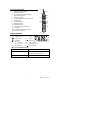
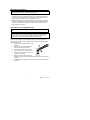
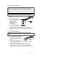
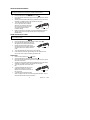
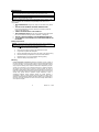
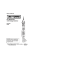
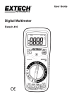
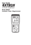
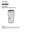
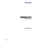
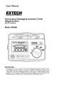
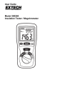
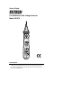
User's Guide
Pen Multimeter with Voltage Detector
Model 381676
Introduction
Congratulations on your purchase of the Extech Model 381676. This instrument
provides AC/DC Voltage, Resistance, Diode, & Continuity testing plus a built-in
non-contact Voltage Detector. Proper use and care of this meter will provide
many years of reliable service.
Safety
WARNING: Improper use of this device can result in electric shock or
damage to the meter. Follow all safety guidelines presented in this
manual and the usual safety precautions used when working with
electrical circuits. This meter has been designed according to IEC-1010
with respect to electronic measurement instrumentation with an
overvoltage category CAT III 600V and pollution 2.
Preliminary Safety
When using the meter, observe all normal safety rules concerning:
• Protection against the dangers of electrical current
• Protection of the meter against misuse
When the meter is delivered, check that it has not been damaged in transit.
When checking voltage, always test the meter on a known live circuit first. Test
leads must be in good condition. Before use, verify that the test lead insulation
is intact and free from lead wire exposure or other damage. Use only the
supplied test leads.
Safety During Use
•
•
•
•
•
•
•
•
•
•
•
•
•
•
Be sure to set the appropriate function and range before use
Never exceed the limits indicated in the specification table of this manual.
Never touch probes, test leads, or alligator clip when connected to live circuit.
Do not measure voltage on terminals that exceed 600V above earth ground.
Always use caution when working with voltages above 60VDC or 30VACrms.
Keep fingers behind probe barrier when taking measurements.
Never connect test leads across a voltage source while the rotary switch is in
the resistance, continuity, or diode mode of operation.
Never perform resistance, continuity, or diode tests on live circuits.
When taking non-contact voltage measurements ensure that the positive test
lead is NOT exposed and that the negative (common) test lead is not
connected to the bottom of the meter.
Before changing functions using the rotary function dial, be sure to
disconnect the meter’s test leads from any circuit under test.
Never use the meter in an explosive environment or where dust, dirt, or
steam exists.
Never use the meter if the housing or battery compartment is open.
Do not store meter in direct sunlight, high temp./humidity, or condensation.
If the equipment is used in a manner not specified by the manufacturer, the
protection provided by the equipment may be impaired.
ALWAYS discharge filter capacitors in power supplies and disconnect the
power when making resistance or diode tests.
Safety Symbols
This symbol adjacent to another symbol, terminal or operating device
indicates that the operator must refer to an explanation in the Operating
Instructions to avoid personal injury or damage to the meter.
This symbol indicates that a device is protected throughout by double
insulation or reinforced insulation.
This symbol advises the user that the terminal(s) so marked must not
be connected to a circuit point at which the voltage with respect to earth
ground exceeds 600V.
This symbol indicates compliance to the European Union directive
381676 V2.0 06/06
2
Controls and Jacks
1
4
5
6
7
9
8
10
12
381676
COM
11
Display Symbols
•)))
2
3
PEN MU LTIMETER+VO LTAGE DETECTO R
1. Retractable positive test lead
2. Test lead retracting nut
3. AC voltage detector and warning light
4. Finger protection barrier
5. Rotary function dial
6. Sensitivity adjustment for AC volt detector
7. RANGE button
8. FUNCTION button
9. MAX HOLD button
10. DATA HOLD button
11. Common (negative) test lead jack
12. LCD display
Note: The battery compartment is located
on the rear of the instrument
Audible Continuity
V
Volts
Diode function
Ω
Ohms
Data Hold
Low battery
D.H
m
milli (10-3) (volts)
DC
Direct current
k
kilo (103) ohms
AC
Alternating current
M
Meg (106) ohms
M.H
Maximum Hold
Max. Input Limit Specification
Measurement
Voltage DC or AC
Input Limit
200mV range: 250VDC or AC
All other ranges: 600VDC or VAC
Resistance, Continuity, and Diode
250VDC or VAC
3
381676 V2.0
06/06
Operating Instructions
WARNING: Risk of electrocution. High-voltage circuits, both AC and DC, are
very dangerous and should be measured with great care.
NOTE: On some low AC and DC voltage ranges, with the test leads not
connected to a device, the display may show a random, changing reading. This
is normal and is caused by the high-input sensitivity. The reading will stabilize
and give a proper measurement when connected to a circuit.
NOTE: The supplied black test leads (standard test lead and alligator clip probe)
have protective plugs that must be removed before being inserted in the bottom
of the meter. The protective apparatus must be removed from the end of the
lead that plugs into the meter.
NON-CONTACT AC VOLTAGE DETECTOR
WARNING: Test the AC voltage detector on a known live circuit before each
use.
WARNING: Before using the meter in the AC Voltage Detector mode, verify that
the batteries are fresh by confirming characters appear on the LCD when the
function dial is turned to the voltage (V) position. Do not attempt to use the
meter as an AC Voltage Detector if the batteries are weak or bad.
With the function switch set to the NCV position, this instrument can detect the
presence of AC voltage (from 50 to 600VAC) simply by being held very near to a
voltage source. The NCV function works when the meter’s function dial is placed in
the NCV position only.
1. Ensure that the retractable test lead is fully
retracted.
2. Disconnect the common (negative) test
lead from the bottom of the meter.
3. Put the function switch to NCV position.
4. Test the detector on a known live circuit.
5. Hold the top of the meter very close to the
voltage source as shown.
6. Adjust the sensitivity dial to the highest
sensitivity position (fully counter-clockwise) and then lower the sensitivity as
required.
7. If voltage is present, the light at the top of the meter will flash and the alarm
will sound.
4
381676 V2.0
06/06
AC VOLTAGE MEASUREMENTS
WARNING: Risk of Electrocution. The probe tips may not be long enough to
contact the live parts inside some 240V outlets for appliances because the
contacts are recessed deep in the outlets. As a result, the reading may show 0
volts when the outlet actually has voltage present. Make sure the probe tips are
touching the metal contacts inside the outlet before assuming that no voltage is
present.
CAUTION: Do not measure AC voltage if a motor on the circuit is being
switched ON or OFF. Large surges may occur that can damage the meter.
1.
Set the function dial to the V
position.
2.
Use the FUNC button to select
AC.
Insert the black test lead banana
plug into the negative jack at the
bottom of the meter.
Unscrew the retracting nut
(clockwise) to draw out the
positive test lead.
Touch the black test probe tip to
the neutral side of the circuit.
Touch the positive test probe tip to the “hot” side of circuit.
Read the voltage on the display. The meter automatically selects the
optimum range or the user may manually select a range using the RANGE
button.
3.
4.
5.
6.
7.
DC VOLTAGE MEASUREMENTS
CAUTION: Do not measure DC voltages if a motor on the circuit is being
switched ON or OFF. Large voltage surges may occur that can damage the
meter.
1.
2.
3.
4.
5.
6.
7.
Set the function dial to the V position.
Use the FUNC button to select DC.
Insert the black test lead banana plug
into the negative jack at the bottom of
the meter.
Carefully turn the positive test lead
retracting nut (located at the top of the meter) clockwise to completely
draw out the positive test lead probe.
Touch the black test probe tip to the negative side of the circuit.
Touch the positive test probe tip to the positive side of the circuit.
Read the voltage on the display. The meter automatically selects the
optimum range or the user may manually select a range using the RANGE
button.
5
381676 V2.0
06/06
RESISTANCE MEASUREMENTS
WARNING: To avoid electric shock, disconnect power to the unit under test and
discharge all capacitors before taking any resistance measurements.
1.
Set the function switch to the Ω
2.
3.
Use the FUNC button to select the resistance mode Ω.
Insert the black test lead banana plug into the negative jack at the bottom
of the meter.
Carefully turn the test lead retracting nut (located at the top of the meter)
clockwise to completely draw out the positive test lead probe.
Touch the test probe tips across the
circuit or part under test. It is best to
disconnect one side of the part under
test from the circuit so the rest of the
circuit will not interfere with the
resistance reading.
Read the resistance on the display. The meter automatically selects the
optimum range or the user may manually select a range using the
RANGE button.
4.
5.
6.
position.
AUDIBLE CONTINUITY CHECK
WARNING: To avoid electric shock, never measure continuity on circuits that
have a voltage potential.
1.
2.
3.
4.
5.
6.
Set the function switch to the Ω
position.
Use the FUNC button to select the audible continuity mode
Insert the black test lead banana plug into
the negative jack at the bottom of the meter.
Carefully turn the test lead retracting nut
(located at the top of the meter) clockwise to
completely draw out the positive test lead
probe.
Touch the test probe tips to the circuit or wire under test.
If the resistance is less than approximately 50Ω, the audible tone will
sound. If the circuit is open, the display will indicate “OL”.
DIODE TEST
1.
2.
3.
4.
5.
6.
7.
Set the function switch to the Ω
position.
Use the FUNC button to select the diode function
Insert the black test lead banana plug into the negative (common) jack at
the bottom of the meter.
Carefully turn the test lead retracting nut (located at the top of the meter)
clockwise to completely draw out the positive test lead probe.
Touch the test probes to the diode under
test.
A good diode will indicate approx. 0.3V
(germanium diodes) to 0.7V (silicon
diodes) for the forward test and “OL” for
the reverse test.
A shorted diode will indicate the same
value of voltage in both the reverse and forward test directions. An open
diode will indicate “OL” in both test directions.
6
381676 V2.0
06/06
DATA HOLD Button
To freeze a displayed reading, press the DATA H button. The reading will freeze
and the D.H display icon will be visible on the LCD. To release the display, press
the DATA H button again. The DH indicator will switch off and the display will
again show real time readings.
MAXIMUM HOLD Button
To display only the highest reading, press the MAX H button. The M.H display
icon will be visible on the display while in the Max Hold mode. Now, the display
will only change when a higher reading than the displayed reading is
encountered. To return to normal operation, press the MAX H button again (the
MH display icon will switch off).
FUNC (Function) BUTTON
The FUNC (function) button is used to select AC or DC while in the VOLTAGE
(V) mode. The FUNC button is also used to select diode , Continuity , or
Resistance Ω while in the Ω
mode.
RANGE Button
The meter automatically selects the optimum range; however, the meter’s
ranges can be selected manually. When using the RANGE button to manually
select a range, start with the highest range and then select successively lower
ranges until the desired range is reached. The decimal place will move with each
press of the RANGE button.
Automatic Power OFF
The meter is equipped with an automatic power off feature to preserve battery
energy. After 15 minutes of inactivity, the meter will automatically turn off. To
turn the meter on again, simply rotate the function switch to the desired function.
Support line (781) 890-7440
Technical support: Extension 200; E-mail: [email protected]
Repair & Returns: Extension 210; E-mail: [email protected]
For the latest version of this User’s Guide, Software updates, and other
up-to-the-minute product information, visit our website: www.extech.com
For up-to-the-minute product information, visit our website: www.extech.com
Extech Instruments Corporation, 285 Bear Hill Rd., Waltham, MA 02451
Copyright © 2006 Extech Instruments Corporation.
All rights reserved including the right of reproduction in whole or in part in any form.
7
381676 V2.0
06/06
Maintenance
WARNING: To avoid electrical shock, disconnect the test leads from any
source of voltage before removing the back cover or the battery cover.
WARNING: To avoid electrical shock, do not operate the meter until the battery
cover is in place and fastened securely.
This meter was designed to provide years of dependable service. However, if the
following guidelines are not followed, the dependability of the meter can be
compromised:
1.
2.
3.
4.
5.
6.
KEEP THE METER DRY. If it gets wet, wipe it off and allow it to dry before
use.
USE AND STORE THE METER IN NORMAL TEMPERATURES.
Environmental extremes can shorten the life of the electronic parts and
distort or melt plastic parts.
HANDLE THE METER GENTLY AND CAREFULLY.
KEEP THE METER CLEAN. Wipe the case occasionally with a damp cloth.
Do not use chemicals, cleaning solvents, abrasives, or detergents.
USE ONLY FRESH BATTERIES OF THE RECOMMENDED SIZE/TYPE.
IF THE METER IS TO BE STORED FOR A LONG PERIOD REMOVE THE
BATTERIES
Battery Replacement
WARNING: To avoid electrical shock, disconnect the test leads from any source of voltage before
removing the battery cover. Do not operate meter unless the batteries are in place.
1.
The
icon will appear when battery voltage is low.
2.
Turn the Function dial to the OFF position.
3.
Disconnect the negative (common) test lead from the meter.
4.
Fully retract the positive test lead probe.
5.
Remove the Phillips head screw at the rear center of the meter housing.
6.
Remove the battery compartment cover to access the batteries.
7.
Replace the two (2) 1.5V ‘AAA’ batteries observing polarity.
8.
Secure the battery compartment cover.
Warranty
EXTECH INSTRUMENTS CORPORATION warrants this instrument to be free of defects in
parts and workmanship for one year from date of shipment (a six month limited warranty applies
on sensors and cables). If it should become necessary to return the instrument for service
during or beyond the warranty period, contact the Customer Service Department at (781) 8907440 ext. 210 for authorization or visit our website at www.extech.com. A Return Authorization
(RA) number must be issued before any product is returned to Extech. The sender is
responsible for shipping charges, freight, insurance and proper packaging to prevent damage in
transit. This warranty does not apply to defects resulting from action of the user such as misuse,
improper wiring, operation outside of specification, improper maintenance or repair, or
unauthorized modification. Extech specifically disclaims any implied warranties or
merchantability or fitness for a specific purpose and will not be liable for any direct, indirect,
incidental or consequential damages. Extech's total liability is limited to repair or replacement of
the product. The warranty set forth above is inclusive and no other warranty, whether written or
oral, is expressed or implied.
8
381676 V2.0
06/06
Specifications
Function
Non-contact AC
Voltage detector
(NCV)
DC Voltage
(VDC)
Range
50 to 600V
Resolution
NA
200mV
2.000V
20V
200V
600V
AC Voltage (VAC) 200mV
(40 – 400Hz)
2.000V
20V
200V
600V
0.1mV
1mV
0.01V
0.1V
1V
0.1V
1mV
0.01V
0.1V
1V
Resistance
(open circuit
voltage: 0.25V)
0.1Ω
0.001kΩ
0.01kΩ
0.1kΩ
0.001MΩ
0.01MΩ
200Ω
2kΩ
20kΩ
200kΩ
2MΩ
20MΩ
Accuracy
±(0.7% reading + 2 digits)
±(0.8% reading + 3 digits)
±(1.0% reading + 3 digits
±(1.0% of reading + 3 digits)
±(1.0% of reading + 1 digit)
±(1.0% of reading + 5 digits)
Accuracy Notes: Accuracy specifications consist of two elements:
• (% reading) – This is the accuracy of the measurement circuit
• (+ digits) – This is the accuracy of the analog to digital converter
Accuracy is stated at 65oF to 83oF (18oC to 28oC) and less than 75% RH
General Specifications
Diode Test:
Continuity Check
Display
Input Impedance
Over-range indication
Auto Power Off
Polarity
Measurement Rate
Low Battery Indication
Batteries
Operating Temperature
Storage Temperature
Operating Humidity
Storage Humidity
Operating Altitude
Weight / Size
Safety
Forward DC bias Current: 1mA approx.;
Reverse DC bias voltage: 1.5V approx.
Overload protection: 250VDC or ACrms
Audible signal will sound if the resistance is less than 50Ω
Open circuit voltage: 0.5V; Overload protection: 250VDC or AC
2000 count (0 to 1999) LCD
10MΩ , AC & DC Voltage
‘OL’ is displayed
After 15 minutes (approx.) of inactivity
Automatic (no indication for positive readings)
Minus (-) sign for negative readings.
2 times per second, nominal
“ ” is displayed to alert battery replacement
Two (2) 1.5V ‘AAA’ batteries
41ºF to 104ºF (5ºC to 40ºC)
-4oF to 140oF (-20oC to 60oC)
Max 80% up to 87ºF (31ºC) decreasing linearly to 50% at
104ºF(40ºC)
<80%
6560ft. (2000meters) operating
3.9oz (110g) / 8.2 x 1.5 x 1.1“(208 x 38 x 29mm)
For indoor use and in accordance with the requirements for double
insulation to IEC1010-1 (1995): EN61010-1 (1995) Overvoltage
Category III, Pollution Degree 2.
9
381676 V2.0
06/06