1
PISO-813
User’s Manual
Warranty
All products manufactured by ICP DAS are warranted
against defective materials for a period of one year from the date
of delivery to the original purchaser.
Warning
ICP DAS assume no liability for damages consequent to the
use of this product. ICP DAS reserves the right to change this
manual at any time without notice. The information furnished by
ICP DAS is believed to be accurate and reliable. However, no
responsibility is assumed by ICP DAS for its use, nor for any
infringements of patents or other rights of third parties resulting
from its use.
Copyright
Copyright 1999 by ICP DAS. All rights are reserved.
Trademark
The names used for identification only may be registered
trademarks of their respective companies.
PISO-813 User’s Manual (Ver.1.2, Oct/2004, PPH-003-12)
-----
1
Tables of Contents
1.
INTRODUCTION ..................................................................................................................4
1.1
FEATURES .................................................................................................................................4
1.2
SPECIFICATIONS ........................................................................................................................5
1.3
ORDER DESCRIPTION ................................................................................................................5
1.3.1
Options ..................................................................................................................5
1.3.2
1.4
2.
PCI Data Acquisition Family.................................................................................6
PRODUCT CHECK LIST ..............................................................................................................6
HARDWARE CONFIGURATION ......................................................................................7
2.1
BOARD LAYOUT ........................................................................................................................7
2.2
A/D CONVERTER OPERATION ...................................................................................................8
2.2.1
A/D Conversion Block Diagram ...........................................................................8
2.3
2.2.2
JP1: Analog Input Range Selection .......................................................................8
2.2.3
JP2: Analog Input Polarity Selection.....................................................................8
2.2.4
Setting Reference ..................................................................................................9
2.2.5
A/D Operation Flow..............................................................................................9
PIN ASSIGNMENT ....................................................................................................................10
2.3.1
Analog Input Connector ......................................................................................10
2.3.2
2.4
DAUGHTER BOARDS................................................................................................................11
2.4.1
DB-8325 Screw Terminal Board ......................................................................... 11
2.4.2
3.
JP9 Reserved .......................................................................................................10
DB-37/ DN-37 general purpose screwing ........................................................... 11
I/O CONTROL REGISTER ...............................................................................................12
3.1
HOW TO FIND THE I/O ADDRESS .............................................................................................12
3.1.1
PIO_DriverInit ....................................................................................................13
3.1.2
PIO_GetConfigAddressSpace .............................................................................14
3.1.3
Show_PIO_PISO.................................................................................................15
3.2
THE ASSIGNMENT OF I/O ADDRESS ........................................................................................16
3.3
THE I/O ADDRESS MAP...........................................................................................................17
3.3.1
RESET\ Control Register ....................................................................................17
3.3.2
A/D Data Register ...............................................................................................18
3.3.3
Multiplexer Channel Select Register...................................................................18
3.3.4
PGA Gain Code Register.....................................................................................19
3.3.5
A/D Trigger Control Register..............................................................................19
PISO-813 User’s Manual (Ver.1.2, Oct/2004, PPH-003-12)
-----
2
4.
DEMO PROGRAM .............................................................................................................20
4.1
PIO_PISO...............................................................................................................................21
4.1.1
PIO_PISO.EXE for Windows .............................................................................22
4.2
DEMO1 ..................................................................................................................................23
PISO-813 User’s Manual (Ver.1.2, Oct/2004, PPH-003-12)
-----
3
1.
Introduction
The PISO-813 is a bus-type isolated 12-bit A/D board for the PCI bus for IBM or
compatible PC. It features a 10KHz data acquisition under DOS and Windows. The
PISO-813 provides 32 channels single-ended analog input. The isolation range of
PISO-813 is increased to 3000Vdc. It is the most cost-effective isolated A/D board for
the PCI bus in the world.
The PISO-813 has one 37-pin D-type connector. It can be installed in a 5V PCI slot
and can support truly “Plug & Play”.
1.1
Features
•
•
•
•
32 single-ended analog input channels
12 bit A/D convert
3000Vdc photo isolation protection
Analog input range
Bipolar: ±10V, ±5V, ±2.5V, ±1.25V, ±0.625V
Unipolar: 0~10V, 0~5V, 0~2.5V, 0~1.25V, 0~0.625V
•
•
•
•
•
•
•
•
Programmable gain control: 1, 2, 4, 8, 16
3000Vdc Isolation DC/DC converter build-in
A/D trigger mode: software trigger
A/D data transfer mode: polling
PCI Bus
One 37-pin D-type connector for isolated analog signal input
SMD, short card
Automatically detected by Windows 95/98/2000/XP
PISO-813 User’s Manual (Ver.1.2, Oct/2004, PPH-003-12)
-----
4
1.2
Specifications
Analog Input Specifications
•
•
•
•
•
•
•
•
•
No. of Channel: 32 single-ended
Resolution: 12 bits
Conversion rate: 10KS/s max.
Input impedance: 10MΩ
Overvoltage protection: ±35V
Accuracy: 0.01% of reading ±1 bit
Linearity: ±1bit
On chip sample & hold
Zero drift: ±25 PPM/ºC of FS max.
Power Requirements: 860mA/+5V max.
General Environmental
•
•
•
•
Operating temp.: 0~50ºC
Storage temp.: -20ºC ~ 70ºC
Humidity: 0~90% non-condensing
Dimensions: 180mm×105mm
1.3
•
PISO-813: 32 channels isolated analog input board with Window driver
1.3.1
•
•
•
Order Description
Options
DB-8325:Daughter board with signal conditioning circuitry
DN-37: I/O connector block with DIN-Rail mounting and 37-pin D-type
connector
DB-37: 37-pin D-type connector pin to pin screw terminal for any 37 pin
D-type connector of I/O board
PISO-813 User’s Manual (Ver.1.2, Oct/2004, PPH-003-12)
-----
5
1.3.2
PCI Data Acquisition Family
We provide a family of PCI-BUS data acquisition cards. These cards can be
divided into three groups as follows:
1. PCI-series: first generation, isolated or non-isolated cards
PCI-1002/1202/1800/1802/1602: multi-function family, non-isolated
PCI-P16R16/P16C16/P16POR16/P8R8: D/I/O family, isolated
PCI-TMC12: timer/counter card, non-isolated
2. PIO-series: cost-effective generation, non-isolated cards
PIO-823/821: multi-function family
PIO-D156/D144/D96/D64/D56/D48/D24: D/I/O family
PIO-DA16/DA8/DA4: D/A family
3. PISO-series: cost-effective generation, isolated cards
PISO-813: A/D card
PISO-P32C32/P32A32/P64/C64/A64: D/I/O family
PISO-P8R8/P8SSR8AC/P8SSR8DC: D/I/O family
PISO-730730A: D/I/O card
PISO-DA2: D/A card
1.4
Product Check List
In addition to this manual, the package includes the following items:
•
•
•
one piece of PISO-813 card
one piece of company floppy diskette or CD
one piece of release note
It is recommended to read the release note firstly. All importance
information will be given in release note as follows:
1. where you can find the software driver & utility
2. how to install software & utility
3. where is the diagnostic program
4. FAQ
Attention!
If any of these items is missing or damaged, contact the dealer from whom you
purchased the product. Save the shipping materials and carton in case you want to ship
or store the product in the future.
PISO-813 User’s Manual (Ver.1.2, Oct/2004, PPH-003-12)
-----
6
2.
Hardware configuration
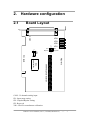
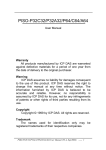
2.1
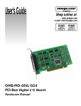
Board Layout
CON1
JP1
2
1
20V
Bipolar
VR4
VR3
VR2
VR1
10V
Unipolar
JP2
JP3
8
7
PISO-813
3000Vdc photo-isolation
PCI
controller
PCI BUS
CON1: 32 channels analog input
JP1: Input range setting
JP2: Unipolar/Bipolar setting
JP3: Reserved
VR1~VR4: For manufacture calibration
PISO-813 User’s Manual (Ver.1.2, Oct/2004, PPH-003-12)
-----
7
2.2
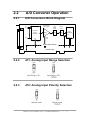
A/D Converter Operation
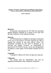
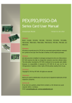
2.2.1
A/D Conversion Block Diagram
Analog Input
Programmable
Gain Amplifier
AI0
AI1
32-Channel
Analog
Multiplexer
PGA
Input
Range
Select
Polarity
Select
JP1
JP2
G2~G0
AI31
D4~D0
A/D
Converter
Trigger
Gain
Code
Status&D11~D0
Channel
select
Photocouple isolation
Control Logic
2.2.2
JP1: Analog Input Range Selection
2.2.3
JP2: Analog Input Polarity Selection
PISO-813 User’s Manual (Ver.1.2, Oct/2004, PPH-003-12)
-----
8
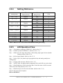
2.2.4
Setting Reference
Analog Input
JP2
Polarity Select
JP1
Range Select
Gain
-10V ~ +10V
Bipolar
20V
1
-5V ~ + 5V
Bipolar
20V
2
10V
1
-2.5V ~ +2.5V
Bipolar
20V
4
10V
2
-1.25V ~ +1.25V
Bipolar
20V
8
10V
4
-0.625 ~ +0.625V
Bipolar
20V
16
10V
8
0 ~10V
Unipolar
10V
1
0 ~ 5V
Unipolar
10V
2
0 ~ 2.5V
Unipolar
10V
4
0 ~ 1.25V
Unipolar
10V
8
0 ~ 0.625V
Unipolar
10V
16
NOTE: Refer to Sec.3.3.4 for more information about gain setting
2.2.5
A/D Operation Flow
Step 1. Find address-mapping of PISO-813. (Refer to Sec.3.1)
Step 2. Enable operation of PISO-813. (Refer to Sec.3.3.1)
Step 3. Make sure the range and polarity of the analog input signal. Select suitable
Setting as show in Sec.2.2.4.
Step 4. Select input channel. (Refer to Sec.3.3.3)
Step 5. delay 10µS. (for photocouple propagation delay and analog multiplexer
settling time)
Step 6. Trigger A/D converter. (Refer to Sec.3.3.5)
Step 7. Delay 70µS. (for photocouple propagation delay and A/D conversion time)
Step 8. Read high byte of A/D conversion data. Check the status of A/D converter
until conversion ready. (Refer to Sec.3.3.2)
Step 9. Read low byte of A/D conversion data. (Refer to Sec.3.3.2)
Step10. A/D conversion complete.
Refer to DEMO1.C
PISO-813 User’s Manual (Ver.1.2, Oct/2004, PPH-003-12)
-----
9
2.3
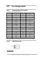
2.3.1
Pin Assignment
Analog Input Connector
CON1: 37-pin D-type female connector
Pin Number
Description
Pin Number
Description
1
AI0
20
AI1
2
AI2
21
AI3
3
AI4
22
AI5
4
AI6
23
AI7
5
AI8
24
AI9
6
AI10
25
AI11
7
AI12
26
AI13
8
AI14
27
AI15
9
AGND
28
AGND
10
AGND
29
AGND
11
AI16
30
AI17
12
AI18
31
AI19
13
AI20
32
AI21
14
AI22
33
AI23
15
AI24
34
AI25
16
AI26
35
AI27
17
AI28
36
AI29
18
AI30
37
AI31
19
AGND
2.3.2
×
JP9 Reserved
Note: Reserved
PISO-813 User’s Manual (Ver.1.2, Oct/2004, PPH-003-12)
-----
10
2.4
Daughter Boards
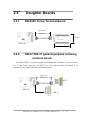
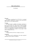
2.4.1
DB-8325 Screw Terminal Board
37pin cable
100/200mm
114mm
PISO-813
220mm
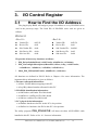
2.4.2
DB-37/ DN-37 general purpose screwing
terminal board
The DB-37/DN-37 is a general purpose terminal board. The DB-37 is direct connect
to a 37-pin D-sub connector, the DN-37 via 37-pin D-sub cable connection. It is
suitable for easy signal connection and measurement.
37pin cable
100/200mm
DN-37
PISO-813
DB-37
PISO-813 User’s Manual (Ver.1.2, Oct/2004, PPH-003-12)
-----
11
3.
I/O Control Register
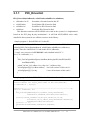
3.1
How to Find the I/O Address
The plug & play BIOS will assign a proper I/O address to every PIO/PISO series
card in the power-up stage. The fixed IDs of PIO/PISO series card are given as
follows:
PISO-813
<Rev1.0>
<Rev2.0>
Vendor ID=
0xE159
Device ID=
0x02
Sub-Vendor ID= 0x80
Vendor ID=
0xE159
Device ID=
0x01
Sub-Vendor ID= 0x4280
Sub-Device ID=
Sub-Aux ID=
Sub-Device ID=
Sub-Aux ID=
0x0A
0x00
0x02
0x00
We provide all necessary functions as follows:
1. PIO_DriverInit(&wBoard, wSubVendor, wSubDevice, wSubAux)
2. PIO_GetConfigAddressSpace(wBoardNo,*wBase,*wIrq, *wSubVendor,
*wSubDevice, *wSubAux, *wSlotBus, *wSlotDevice)
3. Show_PIO_PISO(wSubVendor, wSubDevice, wSubAux)
All functions are defined in PIO.H. Refer to Chapter 4 for more information. The
important driver information is given as follows:
1. Resource-allocated information:
• wBase : BASE address mapping in this PC
• wIrq: IRQ channel number allocated in this PC
2. PIO/PISO identification information:
• wSubVendor: subVendor ID of this board
• wSubDevice: subDevice ID of this board
• wSubAux: subAux ID of this board
3. PC’s physical slot information:
• wSlotBus: hardware slot ID1 in this PC’s slot position
• wSlotDevice: hardware slot ID2 in this PC’s slot position
The utility program,
PIO_PISO.EXE,
will detect & show all PIO/PISO cards
installed in this PC. Refer to Sec. 4.1 for more information.
PISO-813 User’s Manual (Ver.1.2, Oct/2004, PPH-003-12)
-----
12
3.1.1
PIO_DriverInit
PIO_DriverInit(&wBoards, wSubVendor,wSubDevice,wSubAux)
•
•
•
•
wBoards=0 to N
wSubVendor
wSubDevice
wSubAux
number of boards found in this PC
subVendor ID of board to find
subDevice ID of board to find
subAux ID of board to find
This function can detect all PIO/PISO series card in the system. It is implemented
based on the PCI plug & play mechanism-1. It will find all PIO/PISO series cards
installed in this system & save all their resource in the library.
Sample program 1: find all PISO-813 in this PC
wSubVendor=0x80; wSubDevice=0xa; wSubAux=0x00;/* for PISO-813 */
wRetVal=PIO_DriverInit(&wBoards, wSubVendor,wSubDevice,wSubAux);
printf("Threr are %d PISO-813 Cards in this PC\n",wBoards);
/* step2: save resource of all PISO-813 cards installed in this PC */
for (i=0; i<wBoards; i++)
{
PIO_GetConfigAddressSpace(i,&wBase,&wIrq,&wID1,&wID2,&wID3,
&wID4,&wID5);
printf("\nCard_%d: wBase=%x, wIrq=%x", i,wBase,wIrq);
wConfigSpace[i][0]=wBaseAddress; /*save all resource of this card */
wConfigSpace[i][1]=wIrq;
/* save all resource of this card */
}
Sample program 2: find all PIO/PISO in this PC(refer to Sec. 4.1 for more information)
wRetVal=PIO_DriverInit(&wBoards,0xff,0xff,0xff);
/*find all PIO_PISO*/
printf("\nThrer are %d PIO_PISO Cards in this PC",wBoards);
if (wBoards==0 ) exit(0);
printf("\n-----------------------------------------------------");
for(i=0; i<wBoards; i++)
{
PIO_GetConfigAddressSpace(i,&wBase,&wIrq,&wSubVendor,
&wSubDevice,&wSubAux,&wSlotBus,&wSlotDevice);
printf("\nCard_%d:wBase=%x,wIrq=%x,subID=[%x,%x,%x],
SlotID=[%x,%x]",i,wBase,wIrq,wSubVendor,wSubDevice,
wSubAux,wSlotBus,wSlotDevice);
printf(" --> ");
ShowPioPiso(wSubVendor,wSubDevice,wSubAux);
}
PISO-813 User’s Manual (Ver.1.2, Oct/2004, PPH-003-12)
-----
13
3.1.2
PIO_GetConfigAddressSpace
PIO_GetConfigAddressSpace(wBoardNo,*wBase,*wIrq, *wSubVendor,
*wSubDevice, *wSubAux, *wSlotBus, *wSlotDevice)
•
•
•
•
•
•
•
•
wBoardNo=0 to N
wBase
wIrq
wSubVendor
wSubDevice
wSubAux
wSlotBus
wSlotDevice
totally N+1 boards found by PIO_DriveInit(….)
base address of the board control word
allocated IRQ channel number of this board
subVendor ID of this board
subDevice ID of this board
subAux ID of this board
hardware slot ID1 of this board
hardware slot ID2 of this board
The user can use this function to save resource of all PIO/PISO cards installed in
this system. Then the application program can control all functions of PIO/PISO series
card directly.
The sample program source is given as follows:
/* step1: detect all PISO-813 cards first */
wSubVendor=0x80; wSubDevice=0xa; wSubAux=0x0; /* for PISO-813 */
wRetVal=PIO_DriverInit(&wBoards, wSubVendor,wSubDevice,wSubAux);
printf("Threr are %d PISO-813 Cards in this PC\n",wBoards);
/* step2: save resource of all PISO-813 cards installed in this PC */
for (i=0; i<wBoards; i++)
{
PIO_GetConfigAddressSpace(i,&wBase,&wIrq,&t1,&t2,&t3,&t4,&t5);
printf("\nCard_%d: wBase=%x, wIrq=%x", i,wBase,wIrq);
wConfigSpace[i][0]=wBaseAddress;
/* save all resource of this card */
wConfigSpace[i][1]=wIrq;
/* save all resource of this card */
}
/* step3: control the PISO-813 directly */
wBase=wConfigSpace[0][0];
/* get base address the card_0 */
outport(wBase,1);
/* enable all D/I/O operation of card_0 */
wBase=wConfigSpace[1][0];
outport(wBase,1);
/* get base address the card_1 */
/* enable all D/I/O operation of card_1*/
PISO-813 User’s Manual (Ver.1.2, Oct/2004, PPH-003-12)
-----
14
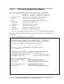
3.1.3
Show_PIO_PISO
Show_PIO_PISO(wSubVendor,wSubDevice,wSubAux)
• wSubVendor
subVendor ID of board to find
• wSubDevice
subDevice ID of board to find
• wSubAux
subAux ID of board to find
This function will show a text string for this special subIDs. This text string is the same
as that defined in PIO.H
The demo program is given as follows:
wRetVal=PIO_DriverInit(&wBoards,0xff,0xff,0xff);
/*find all PIO_PISO*/
printf("\nThrer are %d PIO_PISO Cards in this PC",wBoards);
if (wBoards==0 ) exit(0);
printf("\n-----------------------------------------------------");
for(i=0; i<wBoards; i++)
{
PIO_GetConfigAddressSpace(i,&wBase,&wIrq,&wSubVendor,
&wSubDevice,&wSubAux,&wSlotBus,&wSlotDevice);
printf("\nCard_%d:wBase=%x,wIrq=%x,subID=[%x,%x,%x],
SlotID=[%x,%x]",i,wBase,wIrq,wSubVendor,wSubDevice,
wSubAux,wSlotBus,wSlotDevice);
printf(" --> ");
ShowPioPiso(wSubVendor,wSubDevice,wSubAux);
}
PISO-813 User’s Manual (Ver.1.2, Oct/2004, PPH-003-12)
-----
15
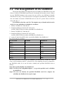
3.2 The Assignment of I/O Address
The plug & play BIOS will assign the proper I/O address to PIO/PISO series card.
If there is only one PIO/PISO board, the user can identify the board as card_0. If there
are two PIO/PISO boards in the system, the user will be very difficult to identify
which board is card_0 ? The software driver can support 16 boards max. Therefore the
user can install 16 boards of PIO/PSIO series in one PC system. How to find the
card_0 & card_1 ?
It is difficult to find the card NO. The simplest way to identify which card is
card_0 is to use wSlotBus & wSlotDevice as follows:
1. Remove all PISO-813 from this PC
2. Install one PISO-813 into the PC’s PCI_slot1,
run PIO_PISO.EXE & record the wSlotBus1 & wSlotDevice1
3. Remove all PISO-813 from this PC
4. Install one PISO-813 into the PC’s PCI_slot2,
run PIO_PISO.EXE & record the wSlotBus2 & wSlotDevice2
5. repeat (3) & (4) for all PCI_slot?, record all wSlotBus? & wSlotDevice?
The records may be as follows:
PC’s PCI slot
WslotBus
wSlotDevice
Slot_1
0
0x07
Slot_2
0
0x08
Slot_3
0
0x09
Slot_4
0
0x0A
Slot_5
1
0x0A
Slot_6
1
0x08
Slot_7
1
0x09
Slot_8
1
0x07
PCI-BRIDGE
The above procedure will record all wSlotBus? & wSlotDevice? in this PC. These
values will be mapped to this PC’s physical slot. This mapping will not be changed for
any PIO/PISO cards. So it can be used to identify the specified PIO/PISO card as
follows:
Step1: Record all wSlotBus? & wSlotDevice?
Step2: Use PIO_GetConfigAddressSpace(…) to get the specified card’s wSlotBus
& wSlotDevice
Step3: The user can identify the specified PIO/PISO card if he compare the
wSlotBus & wSlotDevice in step2 to step1.
PISO-813 User’s Manual (Ver.1.2, Oct/2004, PPH-003-12)
-----
16
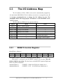
3.3
The I/O Address Map
The I/O address of PIO / PISO series card is automatically assigned by
the main board ROM BIOS. The I/O address can also be re-assigned by user. It
is strongly recommended not to change the I/O address by user. The
plug&play BIOS will assign proper I/O address to each PIO/PISO series
card very well.
The I/O address of PISO-813 are given as follows:
Address
Read
WBase+0
Write
RESET\ control register
Same
WBase+0xd0 Low byte of A/D Data
×
WBase+0xd4 High byte of A/D Data
×
WBase+0xe0
×
Multiplexer channel select register
WBase+0xe4
×
PGA gain code register
WBase+0xf0
×
A/D trigger control register
Note. Refer to Sec. 3.1 for more information about wBase.
3.3.1
RESET\ Control Register
(Read/Write): wBase+0
Bit 7
Bit 6
Bit 5
Bit 4
Bit 3
Bit 2
Bit 1
Bit 0
Reserved Reserved Reserved Reserved Reserved Reserved Reserved RESET\
Note. Refer to Sec. 3.1 for more information about wBase.
When the PC is first power-up, the RESET\ signal is in Low-state. This will
disable all D/I/O operations. The user has to set the RESET\ signal to High-state
before any D/I/O command.
outportb(wBase,1);
/* RESET\ = High all D/I/O are enable now */
outportb(wBase,0);
/* RESET\ = Low
all D/I/O are disable now */
PISO-813 User’s Manual (Ver.1.2, Oct/2004, PPH-003-12)
-----
17
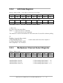
3.3.2
A/D Data Register
(Read): wBase+0xD0 → Low Byte of A/D Conversion Data
Bit 7
Bit 6
Bit 5
Bit 4
Bit 3
Bit 2
Bit 1
Bit 0
D7
D6
D5
D4
D3
D2
D1
D0
(Read): wBase+0xD4 → High Byte of A/D Conversion Data
Bit 7
Bit 6
Bit 5
Bit 4
Bit 3
Bit 2
Bit 1
Bit 0
×
×
×
Status
D11
D10
D9
D8
Note. Refer to Sec. 3.1 for more information about wBase.
×: don’t care
D11~D0: A/D Conversion Data
Status = 0 : A/D conversion is completed
1 : A/D conversion is not completed
The status bit is used as an indicator for A/D conversion. It is used for software polling.
do
{
HighByte=inportb(wBase+0xd4);
}while(HighByte&0x10);
LowByte=inportb(wBase+0xd0);
Data=(HighByte<<8)+LowByte;
3.3.3
/* check status until conversion complete */
Multiplexer Channel Select Register
(Write): wBase+0xe0
Bit 7
Bit 6
Bit 5
Bit 4
Bit 3
Bit 2
Bit 1
Bit 0
×
×
×
D4
D3
D2
D1
D0
Note. Refer to Sec. 3.1 for more information about wBase.
outportb(wBase+0xe0,0);
outportb(wBase+0xe0,1);
outportb(wBase+0xe0,31);
/* Select analog input channel
/* Select analog input channel
/* Select analog input channel
PISO-813 User’s Manual (Ver.1.2, Oct/2004, PPH-003-12)
-----
18
0 */
1 */
31 */
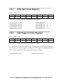
3.3.4
PGA Gain Code Register
(Write): wBase+0xe4
Bit 7
Bit 6
Bit 5
Bit 4
Bit 3
Bit 2
Bit 1
Bit 0
×
×
×
×
×
G2
G1
G0
Note. Refer to Sec. 3.1 for more information about wBase.
/* Select PGM Gain = × 1
*/
/* Select PGM Gain = × 2
*/
/* Select PGM Gain = × 4
*/
/* Select PGM Gain = × 8
*/
/* Select PGM Gain = × 16 */
outportb(wBase+0xe4,0);
outportb(wBase+0xe4,1);
outportb(wBase+0xe4,2);
outportb(wBase+0xe4,3);
outportb(wBase+0xe4,4);
3.3.5
A/D Trigger Control Register
(Write): wBase+0xf0
Bit 7
Bit 6
Bit 5
Bit 4
Bit 3
Bit 2
Bit 1
Bit 0
×
×
×
×
×
×
×
×
Note. Refer to Sec. 3.1 for more information about wBase.
The PISO-813 A/D data transfer mode is polling. Before read the conversion data,
the A/D converter must be trigger by dummy write A/D Trigger Control Register.(Refer
to Sec.2.2.5 for more information about A/D converter operation)
outportb(wBase+0xf0,0);
/* Trigger A/D converter */
PISO-813 User’s Manual (Ver.1.2, Oct/2004, PPH-003-12)
-----
19
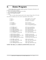
4.
Demo Program
It is recommended to read the release note first. All important information will
be given in release note as follows:
1. where you can find the software driver & utility
2. how to install software & utility
3. where is the diagnostic program
4. FAQ
There are many demo programs given in the company floppy disk or CD. After
the software installation, the driver will be installed into disk as follows:
• \TC\*.*
• \MSC\*.*
• \BC\*.*
for Turbo C 2.xx or above
for MSC 5.xx or above
for BC 3.xx or above
• \TC\LIB\*.*
• \TC\DEMO\*.*
• \TC\DIAG\*.*
for TC library
for TC demo program
for TC diagnostic program
•
•
•
•
•
•
\TC\LIB\Large\*.*
\TC\LIB\Huge\*.*
\TC\LIB\Large\PIO.H
\TC\\LIB\Large\TCPIO_L.LIB
\TC\LIB\Huge\PIO.H
\TC\\LIB\Huge\TCPIO_H.LIB
TC large model library
TC huge model library
TC declaration file
TC large model library file
TC declaration file
TC huge model library file
•
•
•
•
\MSC\LIB\Large\PIO.H
\MSC\LIB\Large\MSCPIO_L.LIB
\MSC\LIB\Huge\PIO.H
\MSC\\LIB\Huge\MSCPIO_H.LIB
MSC declaration file
MSC large model library file
MSC declaration file
MSC huge model library file
•
•
•
•
\BC\LIB\Large\PIO.H
\BC\LIB\Large\BCPIO_L.LIB
\BC\LIB\Huge\PIO.H
\BC\\LIB\Huge\BCPIO_H.LIB
BC declaration file
BC large model library file
BC declaration file
BC huge model library file
NOTE: The library is available for all PIO/PISO series cards.
PISO-813 User’s Manual (Ver.1.2, Oct/2004, PPH-003-12)
-----
20
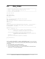
4.1
/*
/*
/*
/*
/*
PIO_PISO
-----------------------------------------------------------Find all PIO_PISO series cards in this PC system
step 1 : plug all PIO_PISO cards into PC
step 2 : run PIO_PISO.EXE
------------------------------------------------------------
*/
*/
*/
*/
*/
#include "PIO.H"
WORD wBase,wIrq;
WORD wBase2,wIrq2;
int main()
{
int i,j,j1,j2,j3,j4,k,jj,dd,j11,j22,j33,j44;
WORD wBoards,wRetVal;
WORD wSubVendor,wSubDevice,wSubAux,wSlotBus,wSlotDevice;
char c;
float ok,err;
clrscr();
wRetVal=PIO_DriverInit(&wBoards,0xff,0xff,0xff); /*for PIO-PISO */
printf("\nThrer are %d PIO_PISO Cards in this PC",wBoards);
if (wBoards==0 ) exit(0);
printf("\n-----------------------------------------------------");
for(i=0; i<wBoards; i++)
{
PIO_GetConfigAddressSpace(i,&wBase,&wIrq,&wSubVendor,
&wSubDevice,&wSubAux,&wSlotBus,&wSlotDevice);
printf("\nCard_%d:wBase=%x,wIrq=%x,subID=[%x,%x,%x],
SlotID=[%x,%x]",i,wBase,wIrq,wSubVendor,wSubDevice,
wSubAux,wSlotBus,wSlotDevice);
printf(" --> ");
ShowPioPiso(wSubVendor,wSubDevice,wSubAux);
}
PIO_DriverClose();
}
NOTE: the PIO_PISO.EXE is valid for all PIO/PISO cards. It can be find in the
\TC\DIAG\ directory. The user can execute the PIO_PISO.EXE to get the following
information:
• List all PIO/PISO cards installed in this PC
• List all resources allocated to every PIO/PISO cards
• List the wSlotBus & wSlotDevice for specified PIO/PISO card identification.
(refer to Sec. 3.2 for more information)
PISO-813 User’s Manual (Ver.1.2, Oct/2004, PPH-003-12)
-----
21
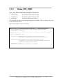
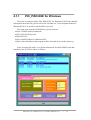
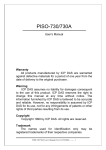
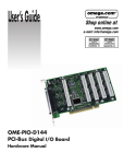
4.1.1
PIO_PISO.EXE for Windows
There has an software utility “PIO_PISO.EXE” for Windows95/98 for the detailed
information about this file, please refer to the “Readme.txt” of development toolkit for
Windows95/98. It is useful for all PIO/PIS series card.
The setup steps from the CD-ROM are given as follows:
• Step1: Toolkit( Software)/Manuals
• Step2: PCI Bus DAQ Card
• Step4: PIO-813
• Step5: Install Toolkits for Windows95/98
• Step6: After installation, this program will be extracted in user define directory.
After executing the utility, every detail information for all PIO/PISO cards that
installed in the PC will be shown as follows:
PISO-813 User’s Manual (Ver.1.2, Oct/2004, PPH-003-12)
-----
22
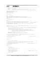
4.2
DEMO1
/* -----------------------------------------------------------/* DEMO1.C : PISO-813
/* Note
: Measure 32-channel A/I.Bipolar range: -10V - +10V
/* -----------------------------------------------------------#include "PIO.H"
WORD Read_AD_Data(void);
WORD wBase,wIrq;
*/
*/
*/
*/
int main()
{
int i,l,h,x,y;
WORD wBoards,wRetVal,AdResult,t1,t2,t3,t4,t5;
WORD wSubVendor,wSubDevice,wSubAux,wSlotBus,wSlotDevice;
char c;
float ok,err,v,k;
clrscr();
/* step 1: find address-mapping of PIO/PISO cards
*/
wRetVal=PIO_DriverInit(&wBoards,0x80,0x0a,0x00); /* for PISO-813 */
printf("\nThrer are %d PISO-813 Cards in this PC",wBoards);
if (wBoards==0) exit(0);
printf("\n--------------- The Configuration Space ---------------");
for(i=0; i<wBoards; i++)
{
PIO_GetConfigAddressSpace(i,&wBase,&wIrq,&wSubVendor,&wSubDevice,
&wSubAux,&wSlotBus,&wSlotDevice);
printf("\nCard_%d:wBase=%x,wIrq=%x,subID=[%x,%x,%x],
SlotID=[%x,%x]",i,wBase,wIrq,wSubVendor,wSubDevice,
wSubAux,wSlotBus,wSlotDevice);
printf(" --> ");
ShowPioPiso(wSubVendor,wSubDevice,wSubAux);
}
PIO_GetConfigAddressSpace(0,&wBase,&wIrq,&t1,&t2,&t3,&t4,&t5);
/* step 2: enable all D/I/O port
*/
outportb(wBase+0,1);
/* enable D/I/O */
i=0;x=1;y=1;
clrscr();
/* Step 3: gain setting
/* Delay more than 5.6us for PGA gain change and optocouple
/* propagation delay 6.0us. (5.6+6.0)us
outportb(wBase+0xe4,0x00);
/* Gain control,G=1
delay(1000);
*/
*/
*/
*/
for(;;)
{
gotoxy(x,y);
printf("Channel %2d ",i);
/* step 4: channel select
outportb(wBase+0xe0,i);
/* step 5: delay 10us
delay(200);
*/
/* channel select = i*/
*/
PISO-813 User’s Manual (Ver.1.2, Oct/2004, PPH-003-12)
-----
23
/* step 6: software trigger
outportb(wBase+0xf0,0x00);
/* step 7: delay 70us
delay(200);
/* software trigger
*/
*/
*/
AdResult=Read_AD_Data();
k=((float)AdResult-2047.0)*10.0/2048.0;
printf(",value = %2.4f",k);
i++;
if (i==0x20) i=0;
y=i+1;
x=1;
if (i>=16)
{
x=40;
y=i-15;
}
if (kbhit()!=0)
{
c=getch(); if ((c=='q') || (c=='Q')) break;
}
}
gotoxy(1,20);
PIO_DriverClose();
}
/* -------------------------------------------------------------WORD Read_AD_Data(void)
{
int LowByte;
WORD HighByte,Data;
char c;
/* step 8: read high byte of A/D result
do
{
HighByte=inportb(wBase+0xd4);
/* Read high byte of A/D data
if (kbhit()!=0) break;
}
while(HighByte&0x10);/* Chech status until convertion complete
/* step 9: read low byte of A/D result
LowByte=inportb(wBase+0xd0);
Data=((HighByte<<8)+LowByte)&0xfff;
return(Data);
/* step 10: A/D conversion complete
}
PISO-813 User’s Manual (Ver.1.2, Oct/2004, PPH-003-12)
-----
24
*/
*/
*/
*/
*/
*/