1
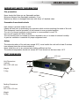
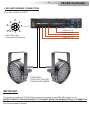
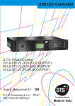
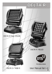
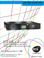
Z8 LED Controller
Datasheet
D.T.S. Code
03.LA.074.V2 (RJ45 OUTPUT)
03.LA.075.V2 (M12 OUTPUT)
03.LA.080.V2 (PLUG-IN OUTPUT)
User’s Manual Rel 2.3 GB
D.T.S. Illuminazione srl - ITALY
http://www.dts-lighting.it
Made in Italy
2
Z8 LED Controller
Le informazioni contenute in questo documento sono state attentamente redatte e controllate. Tuttavia
non è assunta alcuna responsabilità per eventuali inesattezze. Tutti i diritti sono riservati e questo
documento non può essere copiato, fotocopiato, riprodotto per intero o in parte senza previo consenso
scritto della D.T.S .
DTS si riserva il diritto di apportare senza preavviso cambiamenti e modifiche estetiche , funzionali o di
design a ciascun proprio prodotto. D.T.S non assume alcuna responsabilità sull’uso o sull’applicazione
dei prodotti o dei circuiti descritti.
The information contained in this publication has been carefully prepared and checked. However, no
responsibility will be taken for any errors. All rights are reserved and this document cannot be copied,
photocopied or reproduced, in part or completely, without prior written consent from D.T.S.
D.T.S. reserves the right to make any aesthetic, functional or design modifications to any of its products
without prior notice. D.T.S. assumes no responsibility for the use or application of the products or circuits
described herein.
Les informations contenues dans le présent manuel ont été rédigées et contrôlées avec le plus grand
soin. Nous déclinons toutefois toute responsabilité en cas d'éventuelles inexactitudes. Tous droits
réservés. Ce document ne peut être copié, photocopié ou reproduit, dans sa totalité ou partiellement,
sans le consentement préalable de D.T.S.
D.T.S. se réserve le droit d'apporter toutes modifications et améliorations esthétiques, fonctionnelles ou
de design, sans préavis, à chacun de ses produits. D.T.S. décline toute responsabilité sur l'utilisation ou
sur l'application des produits ou des circuits décrits.
Las informaciones contenidas en este documento han sido cuidadosamenteredactadas y
controladas. Con todo, no se asume ninguna responsabilidad por eventuales inexactitudes.
Todos los derechos han sido reservados y este documento no puede ser copiado, fotocopiado
o reproducido, total o parcialmente, sin previa autorizaciónescrita de D.T.S.
D.T.S. se reserva el derecho a aportar sin previo aviso cambios y modificaciones de carácter
estético, funcional o de diseño a cada producto suyo. D.T.S. no se asume responsabilidad de
ningún tipo sobre la utilización o sobre la aplicació
n de los productos o de los circuitos descritos.
3
Z8 LED Controller
DESCRIPTION
Overview
Z8 is a power supply / DMX LED controllers designed to control the following D.T.S. LED products:
FOS 100, FOS 33, TITAN, HELIOS, FOCUS, MINIFOCUS, MR16 LED Range
System
Z8 is fitted with 8 groups of 4 output channels each; max power of each channel is 24W.
Each group can supply and control an independent set-up of D.T.S. LED products at the same
time, like one of the following:
* max 12 x MR16 RGB LED lamps
* max 4 x MR16 Full Color LED lamps
* max 12 x FOCUS RGB LED projectors
* max 4 x FOCUS Full Color LED projectors
* max 3 x FOS 33 LED bars
* max 1 x HELIOS Full Colour LED projector
* max 1 x FOS 100 led bar
* max 1 x TITAN LED projector
Interface
Z8 is fitted with a DISPLAY interface that lets you enter all functions of the internal menu.
DMX
Z8 LED CONTROLLER can be used in 8 DMX modes: 112 ch, 80 ch, 64 ch, 32 ch,14 ch, 10 ch,
1ch or CUSTOM channels mode.
Operating system update
Z8 internal operating system can be updated via computer, through the dedicated D.T.S. RED BOX
interface
Control
Z8 can be controlled by any DMX console.
Construction
Z8 is housed in a sturdy metal case, that offers high resistance to knocks and mechanical stress.
Z8 is rack mountable.
The protection rating against external agents is Ip20.
Connections
DMX IN / OUT connectors: 2 XLR 5-pole by Neutrik and 2 XLR 3-pole by Neutrik
LEDs connector output:
Three models available; RJ45 female connector (03.LA.074.V2) /
8 poles plug-in screw connector (03.LA.080.V2) /
M12 connector (03.LA.075.V2).
The Maximum distance between the Z8 and the last LED unit in the line should not exceed 100
meters for: FOS 100 RGBA / WHITE, FOS 33 RGBA / WHITE (3pcs on the same line).
The Maximum distance between the Z8 and the last LED unit in the line should not exceed 50
meters for: TITAN all models, FOS 100 FULL COLOUR, FOS 33 FULL COLOUR (3pcs on the
same line).
4
Z8 LED Controller
MAIN ELECTRICAL CHARACTERISTICS
Input Voltage Range
Vin 90 - 260 Vac
Frequency
50 - 60 HZ
Power Consumption Range
48 - 800 W
Power Factor ( Pf)
0.95 electronic PFC controller
Efficiency
90% typical
Output
Power Output Range : 8 outputs of 4 channels each.
Max power of each output is 96W (24W per channel).
Max power of each channel is 24W (24W Red, 24W Green, 24W Blue, 24W Amber).
Output Current : 350 mA @ 100% per channel (1,5 - 15W per channel)
500 mA @ 100% per channel in BOOST Mode (1,5 - 24W per channel)
Output Voltage : Vout 48V (Constant Current PWM)
Max Load each output: 15 x MR16 RGB LED lamps or 5 x MR16 Full Color LED lamps or 15 x
FOCUS RGB LED projectors or 5 x FOCUS Full Color LED projectors or 3 x FOS 33 LED bars
or 1 x HELIOS Full Color LED projector or 1 x FOS 100 LED bar or 1 x TITAN LED projector.
Min Load each group: 1 x MR16 RGB LED lamp
Control Input
Control Signal : DMX 512
Dimming System :Constant Current PWM
Address Range : DMX 512 channels addressable by display
5
Z8 LED Controller
IMPORTANT SAFETY INFORMATION
Fire prevention:
Never locate the fixture on any flammable surface.
Minimum distance from flammable materials: 10 cm
Replace any blown or damaged fuses only with those of identical value
Prevention from electric shock:
High voltage is present inside the unit.
Unplug the unit prior to performing any operation which involves touching the inside of the unit.
This equipment must be grounded, do not connect to non-grounded supplies.
The use of a thermal magnetic circuit breaker is recommended for each Z8.
Use only AC supplies 90-260V, 50-60Hz
The unit should never be located in position exposed to rain or in areas of extreme humidity.
A good air ventilation is essential for proper equipment work.
Safety:
The external surface of the unit may exceed 50°C; never handle the unit until at least 5 minutes
have elapsed since the unit was turned off.
Never install the unit in an enclosed area lacking sufficient air flow.
The ambient temperature should not exceed 40°C and should not be lower than -10°C
UNIT DIMENSION
432 mm
Unit Dimensions
(LxDxH)
480 x 385 x 88 mm
88
mm
Weight
7,5 Kg
385 mm
480 mm
Packing Dimensions
(LxDxH)
490 x 390 x 90 mm
Weight
8,5 Kg
6
Z8 LED Controller
INPUT/OUTPUT CONNECTIONS
03.LA.074.V2 (RJ45 OUTPUT)
Mains Switch
Mains 90-260 Vac
50-60 Hz
Powercon female panel
connector
Displays
DMX IN-OUT connectors
8 x LEDs output
RJ45 Female panel connector
Pin 1 = RED +
Pin 2 = RED Pin 3 = GREEN +
Pin 4 = GREEN Pin 5 = BLUE +
Pin 6 = BLUE Pin 7 = AMBER +
Pin 8 = AMBER -
5
1
4
2
1=GND
2=DATA3=DATA+
3
8 1
1
8-pin Female (RJ45)
1
8
8
8-pin Male (RJ45)
Modular Plug
RJ45 : 8P8C
8P8C indicates 8 positions 8 cables
For application where IP65 rating is not necessary, Z8 LEDs cabling connection can be done with a
standard UTP TIA/EIA 568-B2 category 5E cable.
For IP65 rating application, D.T.S. reccomed the use of a IP65/68 cable as the 4X2XAWG24
multipolar black outdoor cable (D.T.S. Code: 0509C062).
The Maximum distance between the Z8 and the last LED unit in the line should not exceed 100
meters for: FOS 100 RGBA / WHITE, FOS 33 RGBA / WHITE (3pcs on the same line).
The Maximum distance between the Z8 and the last LED unit in the line should not exceed 50 meters
for: TITAN all models, FOS 100 FULL COLOUR, FOS 33 FULL COLOUR (3pcs on the same line)
7
Z8 LED Controller
INPUT/OUTPUT CONNECTIONS
03.LA.080.V2 (PLUG-IN OUTPUT)
Mains Switch
Displays
Mains 90-260 Vac
50-60 Hz
Powercon female panel
connector
DMX IN-OUT connectors
5
8 x LEDs output
8 poles plug-in screw connector
Pin 1 = RED +
Pin 2 = RED Pin 3 = GREEN +
Pin 4 = GREEN Pin 5 = BLUE +
Pin 6 = BLUE Pin 7 = AMBER +
Pin 8 = AMBER -
1
4
2
1=GND
2=DATA3=DATA+
3
1---------PIN---------8
8 poles plug-in screw connector
For application where IP65 rating is not necessary, Z8 LEDs cabling connection can be done with a
standard UTP TIA/EIA 568-B2 category 5E cable.
For IP65 rating application, D.T.S. reccomed the use of a IP65/68 cable as the 4X2XAWG24
multipolar black outdoor cable (D.T.S. Code: 0509C062).
The Maximum distance between the Z8 and the last LED unit in the line should not exceed 100
meters for: FOS 100 RGBA / WHITE, FOS 33 RGBA / WHITE (3pcs on the same line).
The Maximum distance between the Z8 and the last LED unit in the line should not exceed 50 meters
for: TITAN all models, FOS 100 FULL COLOUR, FOS 33 FULL COLOUR (3pcs on the same line)
8
Z8 LED Controller
INPUT/OUTPUT CONNECTIONS
03.LA.075.V2 (M12 OUTPUT)
Mains Switch
Mains 90-260 Vac
50-60 Hz
Powercon female panel
connector
Displays
DMX IN-OUT connectors
5
8 x LEDs output
M12 Female panel connector
1
4
2
1=GND
2=DATA3=DATA+
3
Pin 1 = RED +
Pin 2 = RED Pin 3 = GREEN +
Pin 4 = GREEN Pin 5 = BLUE +
Pin 6 = BLUE Pin 7 = AMBER Pin 8 = AMBER +
M12 LED output
Female panel connector
2
3
4
4
8
Pin1 7 6
M12 LED input
Male cable connector
5
5
6
3
2
8
7 Pin1
For application where IP65 rating is not necessary, Z8 LEDs cabling connection can be done with a
standard UTP TIA/EIA 568-B2 category 5E cable.
For IP65 rating application, D.T.S. reccomed the use of a IP65/68 cable as the 4X2XAWG24
multipolar black outdoor cable (D.T.S. Code: 0509C062).
The Maximum distance between the Z8 and the last LED unit in the line should not exceed 100
meters for: FOS 100 RGBA / WHITE, FOS 33 RGBA / WHITE (3pcs on the same line).
The Maximum distance between the Z8 and the last LED unit in the line should not exceed 50 meters
for: TITAN all models, FOS 100 FULL COLOUR, FOS 33 FULL COLOUR (3pcs on the same line)
9
Z8 LED Controller
DMX SIGNAL CONNECTION:
The unit operates using a digital DMX 512 signal. Connection between the controller and the unit or
between units must be carried out using a two pair screened ø 0.5 mm cable and a CANNON XLR 5 pins
connector.
Ensure that the conductors do not touch each other. Do not connect the cable ground to the XLR
chassis. The plug housing must be isolated. Connect the mixer signal to the DMX IN of the Z8 plug and
connect it to the next unit by connecting the DMX OUT plug on the first Z8 to the DMX IN plug of the
second one.
This way, all the projectors are cascade connected.
Standard
DMX 512
controller
5
Standard
DMX 512
controller
5
Standard
DMX 512
controller
5
1
4
2
1=GND
2=DATA3=DATA+
3
1
4
2
1=GND
2=DATA3=DATA+
3
1
4
2
1=GND
2=DATA3=DATA+
3
P.S:If the display showing the DMX address flashes, then one of the following errors has occurred:
- DMX signal not present
- DMX reception problem
For Installations where long distance DMX cable connections are needed, we suggest to use a DMX
terminator.
The DMX terminator is a male XLR 3-5 pins connector with a 120 ohm resistor Between pin 2 and 3.
The DMX terminator must be plugged into the last unit (DMX out panel connector) of the DMX line.
5
1
4
2
3
OUT
PLACE A 120 OHM RESISTOR BETWEEN PIN 2
AND 3 OF A MALE XRL CONNECTOR AND PLUG IT
INTO THE DMX OUT PANEL CONNECTOR OF THE
LAST UNIT CONNECTED TO THE DMX LINE
PIN 3
120 ohm
PIN 2
10
Z8 LED Controller
DMX ADDRESS
Z8 LED CONTROLLER can be used in 8 DMX modes: 112 ch, 80 ch, 64 ch, 32 ch,14 ch, 10 ch,
1ch or CUSTOM channels mode.
If you want to use the Z8 in 32 channels mode, select the “ Full type - 8 bit ” mode from the
DMX MODE menu under MODE SETTINGS and set the following addresses on the mixer:
Projector
Projector
Projector
…..
projector
1
2
3
6
A001
A033
A065
A….
A161
If you want to select the next projector, just add “32”
If you want to use the Z8 in 10 channels mode, select the “ Z1 type - 8 bit ” mode from the
DMX MODE menu under MODE SETTINGS and set the following addresses on the mixer:
Projector 1
A001
Projector 2
A011
Projector 3
A021
…..
A….
projector 6
A051
If you want to select the next projector, just add “10”
Selelcting the DMX address
1) Press the UP-DOWN key until you reach the required DMX address. The numbers on the
display will start flashing (but the new DMX address hasn't yet been set).
2) Press ENTER to confirm your selection. The numbers on the display will stop flashing and the
projector is now controlled by the new DMX address.
TIPS: if you keep pushed the UP or DOWN keys, the channels are calculated more quickly and
you get a faster selection.
11
Z8 LED Controller
DISPLAY FUNCTIONS
Z8 LED DRIVER
Z8 LED CONTROLLER
A001
03.LA.074.V2 (RJ45 OUTPUT)
03.LA.075.V2 (M12 OUTPUT)
03.LA.080.V2 (PLUG-IN OUTPUT)
- FULL TYPE 8 BIT -
MENU
Z8 Software version 2.90
v2.90
UP
ENTER
DOWN
DISPLAY FUNCTIONS
The Z8 display panel shows all the available functions . Using these functions, it is possible to
change some of the parameters and add some functions. Changing the D.T.S. setting can vary the
functions of the unit so that it does not respond to the DMX 512 signal used to control it. Carefully
follow the instructions below before carrying out any variations or selections.
NOTE: the symbol
shows which key has to be pushed to obtain the desired function.
TEST CABLE IN PROGRESS
At the first Start-Up, Z8 is forced in TEST
CABLE MODE (20 % Max LEDs power
output)
This special function let you test all the
LEDs output lines in order to check for
possible problems on LEDs cabling
connections.
Press Enter to confirm and Exit from TEST
Menu
Up-Down
Global setting
ENTER
TEST CABLE
IN PROGRESS
UPLOAD FIRMWARE
Upload the firmware by DMX. This menu allow
to upgrade the unit’s software by computer
DOWNLOAD FIRMWARE
This menu allow to save unit’s programs into
computer
FORCE CABLE TEST
This special function let you test all the LEDs
output lines in order to check for possible
problems on LEDs cabling connections (once
selected, the Z8 should be tuned OFF and ON
again to launch the TEST).
ABOUT
Master pcb code, pcb revision, SW version
ENTER
PRESS ENTER
AFTER TEST OK
DEFAULT SETTING
To restore Factory settings
Up-Down
DEFAULT SETTING
To restore Factory settings
TEST CABLE MODE
Press ENTER to confirm and EXIT from
TEST
GLOBAL
SETTINGS
1. GLOBAL SETTINGS
1. Default settings
2. Upload firmware
3. Download firmware
4. Force cable test
5. About...
UPLOAD FIRMWARE
Upload the firmware via DMX
This menu allow to upgrade the unit’s
software by computer
DOWNLOAD FIRMWARE
This menu allow to save unit’s programs
into computer
FORCE CABLE TEST
This special function let you test all the
LEDs output lines in order to check for
possible problems on LEDs cabling
connections (once selected, the Z8
should be tuned OFF and ON again to
run the TEST).
ABOUT
Master pcb code, pcb revision,
SW version
ENTER
ENTER
ENTER
ENTER
ENTER
12
Menu
Up-Down
Display Setting
ENTER
Up-Down
Flip Visual / Background colour / contrast
level / Screen saver
FLIP VISUAL
Reverses display's reading depending on
the mounting position
(on the ground or suspended).
BACKGROUND COLOUR
To select the colour of the display
background
CONTRAST LEVEL
Display contrast
SCREEN SAVER
This menu allow to activate the screen saver.
Menu
Up-Down
Mode setting
ENTER
DISPLAY
SETTINGS
2. DISPLAY SETTINGS
1. Flip visual
2. Background colour
3. Contrast level
4. Screen saver
Up-Down
DMX MODE
To select DMX mode :
Full Type 8 bit 32 DMX ch.
Full Type 16 bit 64 DMX ch.
Z1 Type 8 bit 10 DMX ch.
Z1 Type 16 bit 14 DMX ch (for Chase and
Cue recording).
Z1 Full 8 bit 10x8=80 DMX ch.
Z1 Full 16 bit 14x8=112 DMX ch.
Custom map control.
1CH Full mode.
MODE
SETTINGS
3. MODE SETTINGS
1. DMX mode
2. Custom mode setup
3. Master mode setup
4. Chase recorder
5. Cue recorder
6. InfraRed mode
7. Emergency setup
Z8 LED Controller
FLIP VISUAL
Flip visual OFF (Default)
Flip visual ON
BACKGROUND COLOR
Background NORMAL (Default)
Background REVERSE
CONTRAST LEVEL
0-100% (default 100%)
SCREEN SAVER
Screen saver TYPE (default disabled)
Screen saver TIME (default 10 sec.)
ENTER
ENTER
ENTER
ENTER
DMX MODE MAP
ENTER
Full type - 8 bit = 32 DMX ch (default)
= RGBA 4ch each output: 1-Red, 2-Green, 3Blue, 4-Amber.
Full type - 16 bit = 64 DMX ch mode
= RGBA 2ch each colour; 8ch each output:
1-Red 8 bit, 2-Red 16 bit, 3-Green 8 bit,
4-Green 16 bit, 5-Blue 8 bit, 6-Blue 16 bit,
7-Amber 8 bit, 8-Amber 16 bit
Z1 type - 8 bit = 10 DMX ch mode with all the
outputs automatically set on DMX starting
channel 1:
1=Shutter, 2=Dimmer, 3=Red, 4=Green,
5=Blue, 6=Amber, 7=White control, 8=CTC,
9=Macro, 10=Function
Z1 type - 16 bit = 14 DMX ch mode with
Dimmer and RGB channels with 16 bit control
and all outputs automatically set on DMX
starting address 1:
1=Shutter, 2=Dimmer, 3=Red 8 bit, 4=Red 16
bit,5=Green 8 bit, 6=Green 16 bit, 7=Blue 8 bit,
8=Blue 16 bit, 9=Amber 8 bit, 10=Amber 16 bit,
11=White control, 12=CTC, 13=Macros,
14=Special Function
Z1 full - 8 bit = (10x8) 80 DMX ch mode same
as Z1 type 8 bit 10ch but each output with
independent DMX control:
Output 1=DMX 1, Output 2= DMX 11, Output
3= DMX 21 ...
Z1 full - 16 bit = (14x8) 112 DMX ch mode
same as Z1 type 16 bit 14ch but each output
with independent DMX control: Output 1 = DMX
1, Output 2 = DMX 15,
Output 3 = DMX 29...
Custom map = DMX mode channels
configuration selectable by user under Custom
mode setup menu
1CH Full = 1 DMX ch mode
13
CUSTOM MODE SETUP
DMX mode channels configuration
selectable by user.
This menu let you set Shutter, Dimmer,
Red, Green, Blue, Amber, Ctc, Macro and
Function to the desired DMX channels.
(Custom map control)
MASTER MODE SETUP
Automatic LEDs output settings without
needing of an external DMX controller.
3 different selectable options with
Dimmer level (Master level output 0-255)
selectable by user:
Master Chase: (Rainbow game or Chase
with 15 programmable scenes), with
Speed time and Wait time selectable by
user.
Master Cue: (7 selectable Cues with
fixed colours)
Master White RGB: (4 selectable Whites
with different colour temperature).
MODE
SETTINGS
3. MODE SETTINGS
1. DMX mode
2. Custom mode setup
3. Master mode setup
4. Chase recorder
5. Cue recorder
6. InfraRed mode
7. Emergency setup
Z8 LED DRIVER
v2.90
TRANSMISSION
ON AIR
- MASTER MODE -
CHASE RECORDER
Chase with 15 user programmable scenes.
(External DMX controller needed)
Z8 is automatically forced to 15 DMX receiving
channels when entering inside the CHASE
RECORDER.
For the programming of Chase by using a
DMX controller, besides the 10 channels
necessary to control the unit (Z1 type - 8 bit
mode) a further 5 DMX channels are needed.
So that in CHASE RECORDER mode the unit
will need 15 channels to be correctly
programmed.
The five new DMX channels are:
DMX CH 11 = Scene number select
Let you select the Scene to be programmed /
viewed (1-15)
DMX ch 12 = Scene status (Edit, Show, Last)
Let you Edit the scenes, View the previously
programmed scenes or Set the last scene of
the chase.
DMX ch 13 = Scene speed (0-240 seconds)
Let you set the Scene speed time
(independend speed time for each scene of
the Chase)
DMX ch 14 = Scene wait (0-240 seconds)
Let you set the Scene Wait time (independend
Wait time for each scene of the Chase)
DMX ch 15 = Store
Let you store the programmed scenes
(Channel 12 “Scene status” should be set to
Edit mode or to Set Last mode)
CUE RECORDER
Single step Cue with Red, Greed, Blue
and Amber output levels selectable by
user
Z8 LED Controller
CUSTOM MODE SETUP
SET dmx order = DMX mode channels
configuration selectable by user.
Block set wizard = let you select the
DMX starting address on every single
output block,
8 output blocks in total.
(Example: block 1 DMX 001, block 2 DMX
006, Block 3 DMX 011....)
Clear block setup = DMX starting
address reset.
ENTER
MASTER MODE SETUP
ENTER
Master selection = Master disable, Master
Chase, Master Cue, Master White RGB.
Chase selection = Chase Rainbow, Chase
Recorded.
Cue Selection = Cue Red, Cue Green , Cue
Blue, Cue RED + Green, Cue Red + Blue,
Cue Green + Blue, Cue Recorded
(configuration selectable by user.)
White selection = White Cold, White
Natural, White Warm, White Full.
Speed Time = Chase speed time (1-240
seconds) default 10 sec.
Wait time = Chase wait time (1-240
seconds) default 10 sec.
Dimmer level = Master level output (0-255)
default 255.
CHASE RECORDER
Scene setup = Scene number, Scene
status, Scene speed, Scene wait.
Restore default = Restore Factory
settings
CUE RECORDER
Cue level Red = Red intensity
(0-255) default 255
Cue level Green = Green intensity
(0-255) default 255
Cue level Blue = Blue intensity (0-255)
default 255
Cue level Amber = Amber intensity
(0-255) Default 255
ENTER
ENTER
14
INFRARED MODE
Infrared remote control.
By activating INFRARED MODE, it will be
possible to navigate trought the unit
functions by using the D.T.S. infrared
remote control. D.T.S. Code :0514L008.
(Internal hardware interface not yet
implemented)
MODE
SETTINGS
3. MODE SETTINGS
EMERGENCY SETUP
Emergency operating mode.
By setting Emergency mode, it will be
possible to select one of the 5
preprogrammed WHITE cues that will
then ran if DMX signal is missing or not
available (Dimmer level also selectable by
user). Usefull for Emergency EXIT
ilumination on public areas.
Menu
Up-Down
LED Setup
ENTER
6. InfraRed mode
7. Emergency setup
Up-Down
Hardware test\ LED min setup\ LED
max setup\ MR16 full colour\ Output
filter\ output delay\ Led BOOST.
LED SETUP
HARDWARE TEST
Complete hardware test
LED MIN SETUP
This menu allow to select the minimum
levels for Red, Green, Blue and Amber
(external DMX controller needed)
LED MAX SETUP
This menu allow to select the maximum
levels for Red, Green, Blue and
Amber(external DMX controller needed)
4.
1.
2.
3.
4.
5.
LED SETUP
Hardware test
Led MIN setup
Led MAX setup
MR16 full colour
Output filter
OUTPUT DELAY
This menu allow to select the value of
the delay ( in millisecons) for RGBA and
Dimmer channels reaction to DMX or
Program variation.
No output delay = 25 ms delay
Short output delay = 80 ms delay
Long output delay = 250 ms delay
LED BOOST
Led BOOST (350mA)
Led BOOST Min (420 mA),
Led BOOST Max (500 mA)
INFRARED MODE
Infrared disabled (default)
Infrared enabled
NOTE:
Internal hardware interface not yet
implemented
External infrared remote sensor needed.
D.T.S. Code :03.LA.016
EMERGENCY SETUP
Mode selection = ON/OFF (default =
OFF)
Macro selection = White COLD,
NATURAL, WARM, FULL, DMX.
Macro DMX Program= Save regolation.
Dimmer level = 0-255 (default = 255)
HARDWARE TEST
Hardware test OFF (default)
Hardware test ON
LED MIN SETUP
(external DMX controller needed)
MIN level RED (default = 0)
MIN level GREEN (default = 0)
MIn level BLUE (default = 0)
MIN level AMBER (default = 0)
LED MAX SETUP
(External DMX controller needed)
MAX level RED (default = 255)
MAX level GREEN (default = 255)
MAX level BLUE (default = 255)
MAX level AMBER (default = 255)
MR16 FULL COLOUR
MR16 limit OFF (Default)
MR16 limit ON
MR16 FULL COLOUR
Preprogrammed RGB values for MR16
full colour led lamp
OUTPUT FILTER
Output filter OFF
Output fileter ON (default)
Z8 LED Controller
4. LED SETUP
6. Output delay
7. Led BOOST
OUTPUT FILTER
Output filter OFF
Output filter ON (Default)
OUTPUT DELAY
No output delay
Short delay (default)
Long delay
LED BOOST
Led BOOST disabled (350mA) Default
Led BOOST MIN (420 mA)
Led BOOST MAX (500 mA)
ENTER
ENTER
ENTER
ENTER
ENTER
ENTER
ENTER
15
Menu
Up-Down
Measure
ENTER
Z8 LED Controller
LIFETIME
Unit lifetime
LED Lifetime
Up-Down
Lifetime\ voltage level \
temperature
ENTER
MEASURE
LIFETIME
This menu show the total
UNIT LIFE TIME (reset not
possible) and the RGB life
TIME (reset possible)
5.
1.
2.
3.
VOLTAGE LEVEL
Internal voltage measure
MEASURE
Lifetime
Voltage level
Temperature
VOLTAGE LEVEL
Internal voltage measure
ENTER
TEMPERATURE
External temperature measure
ENTER
TEMPERATURE
Internnal / External
temperature measure
AUTOMATIC OPERATION (MASTER MODE):
Z8 can work in automatic mode without a DMX controller. First of all connect the projectors with a DMX
cable (picture below). A maximum quantity of 32 slave units can be connected to the same Master unit.
MASTER
SLAVE1
OUT
SLAVE2
IN
OUT
IN
OUT
To activate Automatic mode on the first unit, use the menu to run through the different menus until
MODE SETTING appear, press ENTER, select Master mode Setup, press ENTER, than select Master
selection.
Now it is possible to choose between the different pre-programmed games (Master Chase, Master CUE,
Master White RGB). To confirm game activation press ENTER on the selected GAME.
The first unit that will work as a Master should be set in MASTER mode, the other units have to be set
in 10 channels DMX mode (MODE 10 CH) and the DMX address should be set at A001.
On the master unit it is possible to vary the Speed time for the colour changhing and the Wait time
between the steps ( Master Chase).
16
Z8 LED Controller
DMX PROTOCOL
Z8 RGBA “FULL TYPE - 8 BIT” MAP (32 DMX CHANNELS)
32 CHANNELS MODE
(Default)
1
2
3
4
5
6
7
8
9
10
11
12
13
14
15
16
RED
GREEN
BLUE
AMBER
RED
GREEN
BLUE
AMBER
RED
GREEN
BLUE
AMBER
RED
GREEN
BLUE
AMBER
DMX CHANNEL
DMX range
Value
1
1
1
1
2
2
2
2
3
3
3
3
4
4
4
4
17
18
19
20
21
22
23
24
25
26
27
28
29
30
31
32
1
RED
GREEN
BLUE
AMBER
RED
GREEN
BLUE
AMBER
RED
GREEN
BLUE
AMBER
RED
GREEN
BLUE
AMBER
5
5
5
5
6
6
6
6
7
7
7
7
8
8
8
8
Parameter: RED 1
Mid point
DMX value
Move
range
(degrees)
Mode
Option
000-255
DMX CHANNEL
DMX range
Value
Proportional colour
2
Parameter: GREEN1
Mid point
DMX value
Move
range
(degrees)
Mode
Option
000-255
DMX CHANNEL
DMX range
Value
DMX range
Value
000-255
Function
Proportional colour
3
Parameter: BLUE 1
Mid point
DMX value
Move
range
(degrees)
Mode
Option
Function
Proportional colour
000-255
DMX CHANNEL
Function
4
Parameter: AMBER 1
Mid point
DMX value
Move
range
(degrees)
Mode
Option
Function
Proportional colour
17
DMX CHANNEL
DMX range
Value
5
Parameter: RED 2
Mid point
DMX value
Move
range
(degrees)
Mode
Option
000-255
DMX CHANNEL
DMX range
Value
DMX range
Value
6
Parameter: GREEN 2
Mid point
DMX value
Move
range
(degrees)
Mode
Option
DMX range
Value
7
Parameter: BLUE 2
Mid point
DMX value
Move
range
(degrees)
Mode
Option
DMX range
Value
8
Parameter: AMBER 2
Mid point
DMX value
Move
range
(degrees)
Mode
Option
DMX range
Value
9
Parameter: RED 3
Mid point
DMX value
Move
range
(degrees)
Mode
Option
DMX range
Value
10
Parameter: GREEN 3
Mid point
DMX value
Move
range
(degrees)
Mode
Option
DMX range
Value
000-255
Function
Proportional colour
11
Parameter: BLUE 3
Mid point
DMX value
Move
range
(degrees)
Mode
Option
Function
Proportional colour
000-255
DMX CHANNEL
Function
Proportional colour
000-255
DMX CHANNEL
Function
Proportional colour
000-255
DMX CHANNEL
Function
Proportional colour
000-255
DMX CHANNEL
Function
Proportional colour
000-255
DMX CHANNEL
Function
Proportional colour
000-255
DMX CHANNEL
Z8 LED Controller
12
Parameter: AMBER 3
Mid point
DMX value
Move
range
(degrees)
Mode
Option
Function
Proportional colour
18
DMX CHANNEL
DMX range
Value
13
Parameter: RED 4
Mid point
DMX value
Move
range
(degrees)
Mode
Option
000-255
DMX CHANNEL
DMX range
Value
DMX range
Value
14
Parameter: GREEN 4
Mid point
DMX value
Move
range
(degrees)
Mode
Option
DMX range
Value
15
Parameter: BLUE 4
Mid point
DMX value
Move
range
(degrees)
Mode
Option
DMX range
Value
16
Parameter: AMBER 4
Mid point
DMX value
Move
range
(degrees)
Mode
Option
DMX range
Value
17
Parameter: RED 5
Mid point
DMX value
Move
range
(degrees)
Mode
Option
DMX range
Value
18
Parameter: GREEN 5
Mid point
DMX value
Move
range
(degrees)
Mode
Option
DMX range
Value
000-255
Function
Proportional colour
19
Parameter: BLUE 5
Mid point
DMX value
Move
range
(degrees)
Mode
Option
Function
Proportional colour
000-255
DMX CHANNEL
Function
Proportional colour
000-255
DMX CHANNEL
Function
Proportional colour
000-255
DMX CHANNEL
Function
Proportional colour
000-255
DMX CHANNEL
Function
Proportional colour
000-255
DMX CHANNEL
Function
Proportional colour
000-255
DMX CHANNEL
Z8 LED Controller
20
Parameter: AMBER 5
Mid point
DMX value
Move
range
(degrees)
Mode
Option
Function
Proportional colour
19
DMX CHANNEL
DMX range
Value
21
Parameter: RED 6
Mid point
DMX value
Move
range
(degrees)
Mode
Option
000-255
DMX CHANNEL
DMX range
Value
DMX range
Value
22
Parameter: GREEN 6
Mid point
DMX value
Move
range
(degrees)
Mode
Option
DMX range
Value
23
Parameter: BLUE 6
Mid point
DMX value
Move
range
(degrees)
Mode
Option
DMX range
Value
24
Parameter: AMBER 6
Mid point
DMX value
Move
range
(degrees)
Mode
Option
DMX range
Value
25
Parameter: RED 7
Mid point
DMX value
Move
range
(degrees)
Mode
Option
DMX range
Value
26
Parameter: GREEN 7
Mid point
DMX value
Move
range
(degrees)
Mode
Option
DMX range
Value
000-255
Function
Proportional colour
27
Parameter: BLUE 7
Mid point
DMX value
Move
range
(degrees)
Mode
Option
Function
Proportional colour
000-255
DMX CHANNEL
Function
Proportional colour
000-255
DMX CHANNEL
Function
Proportional colour
000-255
DMX CHANNEL
Function
Proportional colour
000-255
DMX CHANNEL
Function
Proportional colour
000-255
DMX CHANNEL
Function
Proportional colour
000-255
DMX CHANNEL
Z8 LED Controller
28
Parameter: AMBER 7
Mid point
DMX value
Move
range
(degrees)
Mode
Option
Function
Proportional colour
20
DMX CHANNEL
DMX range
Value
29
Parameter: RED 8
Mid point
DMX value
Move
range
(degrees)
Mode
Option
000-255
DMX CHANNEL
DMX range
Value
DMX range
Value
30
Parameter: GREEN 8
Mid point
DMX value
Move
range
(degrees)
Mode
Option
DMX range
Value
000-255
Function
Proportional colour
31
Parameter: BLUE 8
Mid point
DMX value
Move
range
(degrees)
Mode
Option
Function
Proportional colour
000-255
DMX CHANNEL
Function
Proportional colour
000-255
DMX CHANNEL
Z8 LED Controller
32
Parameter: AMBER 8
Mid point
DMX value
Move
range
(degrees)
Mode
Option
Function
Proportional colour
21
Z8 LED Controller
DMX PROTOCOL
Z8 RGBA “Z1 TYPE - 8 BIT” MAP (10 DMX CHANNELS)
10 CHANNELS MODE
1
2
3
4
5
6
7
8
9
10
SHUTTER
DIMMER
RED
GREEN
BLUE
AMBER
WHITE (Pre-programmed whites at different colour temperatures)
CTC
COLOURS MACRO
FUNCTIONS
DMX CHANNEL
1
DMX range
Value
Mid point
DMX value
0-9
10-19
20-29
30-119
120-149
150-179
180-204
205-229
230-255
5
14
24
Parameter: SHUTTER
Move
range
(degrees)
Mode
Option
Black-out
Open
Black-out
Strobe at variable speed from slow to fast (3400ms-20ms)
Pulse open at variable speed from slow to fast (43s-100ms)
Pulse close at variable speed from slow to fast (43s-100ms)
Random Strobe (Master and RGBA active)
Random Strobe (Full)
Open
192
218
240
DMX CHANNEL
2
DMX range
Value
Mid point
DMX value
Parameter: DIMMER
Move
range
(degrees)
Mode
Option
0-255
DMX CHANNEL
DMX range
Value
0-255
Function
Function
Proportional dimmer
3
Parameter: RED
Mid point
DMX value
Move
range
(degrees)
Mode
Option
Function
Proportional colour
22
DMX CHANNEL
DMX range
Value
4
Z8 LED Controller
Parameter: GREEN
Mid point
DMX value
Move
range
(degrees)
Mode
Option
0-255
DMX CHANNEL
DMX range
Value
Proportional colour
5
Parameter: BLUE
Mid point
DMX value
Move
range
(degrees)
Mode
Option
0-255
DMX CHANNEL
DMX range
Value
Function
Proportional colour
6
Parameter: AMBER
Mid point
DMX value
Move
range
(degrees)
Mode
Option
0-255
DMX CHANNEL
Function
Function
Proportional colour
7
Parameter: WHITE (Pre-programmed White at diff. color temperature)
DMX range
Value
Mid point
DMX value
0-55
56-105
106-155
23
80
130
Move
range
(degrees)
Mode
Option
Function
No Function
Full (Red-Green-Blue at Full)
White DTS
IF CHANNEL 10 (FUNCTIONS) = CUSTOM WHITE RECALL (Dmx range value 0 - 79)
156-205
180
Custom White Recall
White CTC (Channel 8 CTC enabled
225
206-255
43 color temp. Correction Macros: 2000°K-7200°K)
IF CHANNEL 10 (FUNCTIONS) = CUSTOM WHITE CREATE (Dmx range value 80 - 160)
156-205
180
Custom White Create (RGB levels selectable by DMX)
206-255
225
White CTC (Channel 8 CTC enabled
43 color temp. Correction Macros: 2000°K-7200°K)
23
DMX CHANNEL
DMX range
Value
8
Z8 LED Controller
Parameter: CTC (Color temperature correction)
Mid point
DMX value
Move
range
(degrees)
Mode
Option
Function
IF CHANNEL 7 (White) = WHITE CTC (Dmx range value 206 - 255)
43 color temp. Correction Macros: 0 = 2000°K / 128 = 5500°K / 255 = 7200°K
0-255
IF CHANNEL 7 (White) = NO FUNCTION (Dmx range value 0 - 43)
Smooth RGB linear Hue correction
0-255
DMX CHANNEL
DMX range
Value
9
Parameter: COLOUR MACROS
Mid point
DMX value
Mode
Option
Function
No Function
Macro 1
Macro 2
Macro 3
Macro 4
Macro 5
Macro 6
Macro 7
Macro 8
Macro 9
Macro 10
Macro 11
Macro 12
Macro 13
Macro 14
Macro 15
Macro 16
0-14
15-29
30-44
45-59
60-74
75-89
90-104
105-119
120-134
135-149
150-164
165-179
180-194
195-209
210-225
226-239
240-255
DMX CHANNEL
10
DMX range
Value
Mid point
DMX value
0-79
80-160
161-255
Move
range
(degrees)
Parameter: FUNCTIONS (Recall,Create and Store the Custom white)
Move
Mode
Option
Function
range
(degrees)
Custom White Recall (Enable CH 7 for Custom white Recall)
Custom White Create (Enable CH 7 for Custom white Creation)
Custom White Store (Store the Custom White created )
24
Z8 LED Controller
WIRING DIAGRAMS
Z8 is available in three versions with different LED output connectors:
RJ45 female connector (03.LA.074.V2), 8 poles plug-in screw connector (03.LA.080.V2)
and M12 connector (03.LA.075.V2).
RJ45 Female
panel connector
on board :
Z8 LED
CONTROLLER
(03.LA.074.V2)
RJ45 LED input
male cable connector
on board:
HELIOS R / RA7 HEAD
8 1
1
8
1
8
8-pin Female (RJ45)
8 poles plug-in
screw connector
on board :
Z8 LED
CONTROLLER
(03.LA.080.V2)
LEDS
CONNECTOR PINOUT (Rj45)
Pin 1 = RED +
Pin 2 = RED Pin 3 = GREEN +
Pin 4 = GREEN Pin 5 = BLUE +
Pin 6 = BLUE Pin 7 = AMBER +
Pin 8 = AMBER -
LEDS
CONNECTOR PINOUT
8 poles plug-in
screw connector
Pin 1 = RED +
Pin 2 = RED Pin 3 = GREEN +
Pin 4 = GREEN Pin 5 = BLUE +
Pin 6 = BLUE Pin 7 = AMBER +
Pin 8 = AMBER -
1---------PIN---------8
8 poles plug-in screw connector
M12 LED output
Female panel connector
on board :
Z8 LED
CONTROLLER
(03.LA.075.V2)
2
3
4
4
8
Pin1 7 6
M12 LED input
Male cable connector
on board:
FOS 100 - FOS 33
TITAN
5
5
6
3
2
8
7 Pin1
LEDS
CONNECTOR PINOUT (M12)
Pin 1 = RED +
Pin 2 = RED Pin 3 = GREEN +
Pin 4 = GREEN Pin 5 = BLUE +
Pin 6 = BLUE Pin 7 = AMBER Pin 8 = AMBER +
25
Z8 LED Controller
LED UNITS WIRING CONNECTION
03.LA.074.V2 (RJ45 OUTPUT)
8 1
8-pin Female (RJ45)
LEDs OUT 5
LEDs OUT 4
LEDs OUT 3
6 1
D.T.S. T-BOX
B
R
1
CODE 03.LA.001
T BOX
INPUT OUT 2
OUT 1
G
6-pin Female (RJ12)
INPUT
OUT 2
OUT 1
B
R
2
IMPORTANT:
T BOX
INPUT OUT 2
OUT 1
G
MR16 RGB
Never plug the cable coming from the Power supply
into OUT 1 or OUT 2 of the T-BOX when other MR16
lamps are connected, because a wrong connection
can seriously damage the lamps.
B
R
T BOX
INPUT OUT 2
OUT 1
G
MR16 RGB
3
The maximum number of MR16 / FOCUS RGB LED
lamps connectable to each Z8 LEDs output is 12 pcs.
NEVER CONNECT NOR DISCONNECT A MR16
UNIT WHEN THE POWER SUPPLY IS TURNED ON.
The Maximum distance between the Z8 and the last
MR16 unit in the line should not exceed 100 meters
MR16 RGB
B
R
12
Pin 1
G
6 1
6-pin Female (RJ12)
MR16 RGB
26
Z8 LED Controller
LED UNITS WIRING CONNECTION
03.LA.074.V2 (RJ45 OUTPUT)
8 1
8-pin Female (RJ45)
LEDs OUT 5
LEDs OUT 4
LEDs OUT 3
6 1
6-pin Female (RJ12)
D.T.S. T-BOX
T BOX
INPUT OUT 2
OUT 1
1
CODE 03.LA.001
INPUT
OUT 2
FOCUS FULL COLOUR
OUT 1
6-pin Male (RJ12)
Modular Plug
T BOX
INPUT OUT 2
OUT 1
2
IMPORTANT:
FOCUS FULL COLOUR
T BOX
INPUT OUT 2
OUT 1
3
The maximum number of MR16 / FOCUS FULL
COLOUR LED projectors connectable to each Z8
LEDs output is 4 pcs.
Never plug the cable coming from the Power supply
into OUT 1 or OUT 2 of the T-BOX when other MR16
/ FOCUS FULL COLOUR units are connected,
because a wrong connection can seriously damage
the lamps.
NEVER CONNECT NOR DISCONNECT A MR16
UNIT WHEN THE POWER SUPPLY IS TURNED ON.
The Maximum distance between the Z8 and the last
MR16 unit in the line should not exceed 100 meters
FOCUS FULL COLOUR
4
6 1
6-pin Female (RJ12)
FOCUS FULL COLOUR
27
Z8 LED Controller
LED UNITS WIRING CONNECTION
03.LA.080.V2 (8 POLES PLUG-IN OUTPUT)
LEDs OUT 5
LEDs OUT 4
LEDs OUT 3
LEDs OUT 2
1---------PIN---------8
8 poles plug-in screw connector
LEDS OUTPUT
1 2
3 4
5 6 7
LEDS OUTPUT
8
R+ R- G+ G- B+ B- A+ A-
1 2
3 4
5 6 7
8
R+ R- G+ G- B+ B- A+ A-
FOS 33 FULL COLOUR
FOS 33 RGBA
FOS 33 WHITE+AMBER
FOS 100 FULL COLOUR
FOS 100 RGBA
FOS 100 WHITE+AMBER
IMPORTANT:
The maximum number of FOS 100 LED bar connectable to each Z8 LEDs output is 1 pc.
The maximum number of FOS 33 LED bars connectable to each Z8 LEDs output is 3 pc.
NEVER CONNECT NOR DISCONNECT A FOS UNIT WHEN THE POWER SUPPLY IS TURNED ON.
The Maximum distance between the Z8 and the FOS 100 FULL COLOUR unit should not exceed 50
meters.
The Maximum distance between the Z8 and the last FOS 33 FULL COLOUR unit in the line (3 pcs) should
not exceed 50 meters
The Maximum distance between the Z8 and the FOS 100 RGBA / WHITE unit should not exceed 100
meters.
The Maximum distance between the Z8 and the last FOS 33 RGBA / WHITE unit in the line (3 pcs) should
not exceed 100 meters
28
Z8 LED Controller
LED UNITS WIRING CONNECTION
03.LA.075.V2 (M12 OUTPUT)
2
3
4
8
5
Pin1 7 6
LEDs OUT 8
LEDs OUT 5
LEDs OUT 4
M12 LED output
Female panel connector
LEDs OUT 3
TITAN RGBA
TITAN FULL COLOUR
TITAN WHITE+AMBER
IMPORTANT:
The maximum number of TITAN LED projector connectable to each Z8 LEDs output is 1 pc.
NEVER CONNECT NOR DISCONNECT A TITAN UNIT WHEN THE POWER SUPPLY IS TURNED ON.
The Maximum distance between the Z8 and the TITAN FULL COLOUR / RGBA / WHITE+AMBER unit
should not exceed 50 meters.
29
NOTES
Z8 LED Controller
30
NOTES
Z8 LED Controller
31
NOTES
Z8 LED Controller
The information contained in this publication has been carefully prepared and checked.
However, no responsibility will be taken for any errors. All rights are reserved and this document
cannot be copied, photocopied or reproduced, in part or completely, without prior written consent
from D.T.S.
D.T.S. reserves the right to make any aesthetic, functional or design modifications to any of its
products without prior notice. D.T.S. assumes no responsibility for the use or application of the
products or circuits described herein.
MADE IN ITALY
ISO 9001:2008
D.T.S. quality system
is certified to the
ISO 9001:2008 standard
D.T.S. products are designed
and manufactured at the D.T.S.
plants in italy
*0517I155*
0517I155
D.T.S. Illuminazione s.r.l - Via Fagnano Selve 10-12-14 47843 - Misano Adriatico (RN) Italy
Tel. +39 0541 611131 Fax +39 0541 611111
[email protected] www.dts-lighting.it