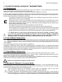
1
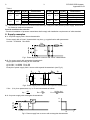
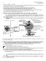
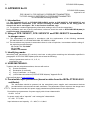
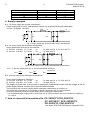
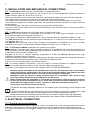
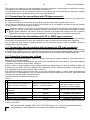
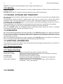
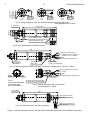
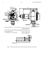
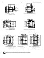
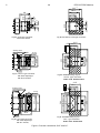
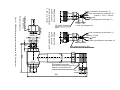
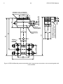
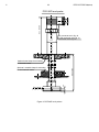
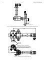
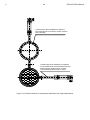
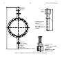
DTR.PCE.PRE-28(ENG)
APLISENS
MANUFACTURE OF PRESSURE TRANSMITTERS
AND CONTROL INSTRUMENTS
USER’S MANUAL
PRESSURE TRANSMITTERS
PCE-28
DIFFERENTIAL PRESSURE TRANSMITTERS
PRE-28
HYDROSTATIC LEVEL PROBES
PCE-28P
Edition C
WARSAW JUNE 2010
APLISENS JSC 03-192 Warszawa, ul. Morelowa 7
tel. +48 22 814 07 77; fax +48 22 814 07 78
www.aplisens.pl, e-mail: [email protected]
Symbols used
Symbol
i
Description
Warning to proceed strictly in accordance with the information contained in the
documentation in order to ensure the safety and full functionality of the device.
Information particularly useful during installation and operation of the device.
Information particularly useful during installation and operation of a type Ex device.
Information on disposal of used equipment
BASIC REQUIREMENTS AND SAFE USE
- The manufacturer will not be liable for damage resulting from incorrect installation,
failure to maintain the device in a suitable technical condition, or use of the device
other than for its intended purpose.
- Installation should be carried out by qualified staff having the required authorizations to
install electrical and pressure-measuring devices. The installer is responsible for performing
the installation in accordance with these instructions and with the electromagnetic
compatibility and safety regulations and standards applicable to the type of installation.
- Installation should be carried out by qualified staff having the required authorizations to
install electrical and pressure-measuring devices. The installer is responsible for performing
the installation in accordance with these instructions and with the electromagnetic
compatibility and safety regulations and standards applicable to the type of installation..
- If a device is not functioning correctly, disconnect it and send it for repair to the manufacturer
or to a firm authorized by the manufacturer.
In order to minimize the risk of malfunction and associated risks to staff, the device is not to be
installed or used in particularly unfavourable conditions, where the following dangers occur:
- possibility of mechanical impacts, excessive shocks and vibration;
- excessive temperature fluctuation, exposure to direct sunlight;
- condensation of water vapour, dust, icing.
Installation of intrinsic safety versions should be performed with particular care, in accordance
with the regulations and standards applicable to that type of installation.
The manufacturer reserves the right to make changes (not having a negative impact on the
operational and metrological parameters of the products) without updating the contents of the
technical manual.
C
1
DTR.PCE.PRE-28(ENG)
CONTENTS
I. APPENDIX EX.02......................................................................................................................................... 2
II. APPENDIX EX.03........................................................................................................................................ 5
1. INTRODUCTION ......................................................................................................................................... 7
2. USER MATERIALS ..................................................................................................................................... 7
3. APPLICATIONS AND MAIN FEATURES .................................................................................................... 7
4. IDENTIFYING MARKS. ORDERING PROCEDURE .................................................................................... 8
5. TECHNICAL DATA ..................................................................................................................................... 8
5.1. PCE–28. TECHNICAL DATA ..................................................................................................................... 8
5.1.1. PCE–28. MEASUREMENT RANGES ....................................................................................................................... 8
5.1.2. PCE–28. METROLOGICAL PARAMETERS .............................................................................................................. 8
5.1.3. METROLOGICAL PARAMETERS PCE-28 FOR PED VERSION. .................................................................................. 8
5.2. PRE–28. TECHNICAL DATA ..................................................................................................................... 8
5.2.1. PRE–28. MEASUREMENT RANGES ....................................................................................................................... 8
5.2.2. PRE–28. METROLOGICAL PARAMETERS .............................................................................................................. 9
5.3. PCE-28, PRE-28.- COMMON PARAMETERS............................................................................................... 9
5.3.1. PCE–28, PRE–28 . ELECTRICAL PARAMETERS ................................................................................................... 9
5.3.2. PCE–28, PRE–28. PERMITTED ENVIRONMENTAL CONDITIONS ............................................................................. 9
5.3.2. PCE–28, PRE–28. CONSTRUCTION MATERIALS .................................................................................................. 9
5.4. PRESSURE CONNECTORS ........................................................................................................................10
5.4.1. PCE–28. PRESSURE CONNECTORS.................................................................................................................... 10
5.4.2. PRE–28. PRESSURE CONNECTORS.................................................................................................................... 10
5.5. PCE–28, PRE–28. ELECTRICAL CONNECTORS AND INGRESS PROTECTION RATING OF CASE .................................10
6. CONSTRUCTION.......................................................................................................................................10
6.1. MEASUREMENT PRINCIPLES ....................................................................................................................10
6.2. CONSTRUCTION......................................................................................................................................10
6.3. CASING, ELECTRICAL CONNECTIONS........................................................................................................10
7. PLACE OF INSTALLATION OF TRANSMITTERS.....................................................................................11
7.1. GENERAL NOTE ......................................................................................................................................11
7.2. LOW AMBIENT TEMPERATURE .................................................................................................................11
7.3. HIGH MEDIUM TEMPERATURE. .................................................................................................................11
7.4. MECHANICAL VIBRATION, CORROSIVE MEDIA. ..........................................................................................11
8. INSTALLATION AND MECHANICAL CONNECTIONS ..............................................................................12
9. ELECTRICAL CONNECTION ....................................................................................................................12
9.1. GENERAL RECOMMENDATIONS .................................................................................................................12
9.2. CONNECTIONS FOR TRANSMITTERS WITH PD-TYPE CONNECTOR..................................................................13
9.3. CONNECTIONS FOR TRANSMITTERS WITH PK OR PM12-TYPE CONNECTOR...................................................13
9.4. CONNECTIONS FOR TRANSMITTERS WITH TERMINAL BOX (PZ-TYPE CONNECTOR). .........................................13
9.5. PROTECTION FROM EXCESS VOLTAGE .......................................................................................................13
9.6. EARTHING..............................................................................................................................................14
10. SETTING OF ZERO POSITION AND MEASUREMENT RANGE..............................................................14
11. SERVICES AND SPARE PARTS. ............................................................................................................14
11.1. PERIODIC SERVICE ................................................................................................................................14
11.2. UNSCHEDULED SERVICES ......................................................................................................................14
11.3. CLEANING THE DIAPHRAGM SEAL, OVERLOADING DAMAGE......................................................................14
11.4. SPARE PARTS. .....................................................................................................................................14
12. PCE-28P LEVEL PROBES.......................................................................................................................15
12.1. APPLICATIONS .....................................................................................................................................15
12.2. PCE–28P. TECHNICAL DATA ................................................................................................................15
12.3. PRINCIPLES OF OPERATION, CONSTRUCTION ..........................................................................................15
12.4. PLACE AND METHOD OF INSTALLATION. FITTING ......................................................................................15
12.5. ELECTRICAL CONNECTION. SETTINGS .....................................................................................................15
12.6. EARTHING............................................................................................................................................16
13. PACKING, STORAGE AND TRANSPORT...............................................................................................16
14. GUARANTEE...........................................................................................................................................16
15. ADDITIONAL INFORMATION ..................................................................................................................16
16. FIGURES .................................................................................................................................................16
C
2
DTR.PCE.PRE-28(ENG)
I. APPENDIX Ex.02
1453
DTR.PCE.PRE-28(ENG)
Appendix Ex.02
PCE–28/XX/YY, PCE–28P/XX/YY PRESSURE TRANSMITTERS,
TYP PRE–28/XX/YY DIFFERENTIAL PRESSURE TRANSMITTER
Ex VERSIONS according to ATEX
1. Introduction
1.1. The “Appendix Ex.02” to DTR.PCE.PRE-28(ENG) applies to PCE-28/XX/YY, PCE-28P/XX/YY and
and PRE-28/XX/YY transmitters in Ex version according to ATEX, marked on the rating plate as shown
in 2.2 and 3. and signed “Ex” in the Product Certificate, only.
1.2. The appendix contains supplementary information relating to the Ex version transmitters.
During installation and use of the Ex transmitters, reference should be made to DTR.PCE.PRE-28(ENG) in
conjunction with “Appendix Ex.02”.
2. Using of PCE–28/XX/YY, PCE–28P/XX/YY and PRE–28/XX/YY transmitters
in danger zones.
2.1. The PCE–28, PCE–28P and PRE–28 transmitters are produced in accordance with the requirements
of the following standards: EN 60079-0:2004, EN 50303:2000, EN 60079-26:2007, EN 60079-11:2007,
EN 61241-0:2006, EN 61241-11:2006
2.2. The transmitters may operate in areas where there is a risk of explosion, in accordance with the rating of
the explosion protection design:
II 1/2G, Ga/Gb Ex ia IIC T4/T5/T6
I M1 Ex ia I
II 1D Ex ia D20 T105°°C
KDB 08ATEX002X
3. Identifying marks
Intrinsically safe transmitters (Ex version) must have a rating plate containing the information specified in
paragraph 4 of DTR.PCE.PRE-28(ENG) and also at least the following:
-
CE mark and the notified unit number: 1453, mark
-
designation of explosion protection design, certificate number
values of parameters such as: Ui, Ii, Ci, Li
type of electrical and process connectors
manufacture year and serial number
4. User information.
Together with the transmitters, user will receive: User’s Manual signed DTR.PCE.PRE-28 (ENG) with the
Appendix Ex.02, and the Product Certificate.
5. Permissible input parameters (based on data from the KDB 08ATEX002X
certificates and certification documentation).
The transmitters should be powered via the associated power supplier and measurement devices
provided with the relevant intrinsic-safe certificates. The parameters of their outputs to the danger zone
should not exceed the limit power supply parameters specified below for the transmitters:
The pressure transmitter is an intrinsic safety apparatus with level of protection “ia”, when supply
circuit have level of protection “ia”.
- for power supply with a linear characteristic
Ui = 28V Ii = 0,1A
- for power supply with a “trapezial” and “rectangular” characteristic
Ui = 24V Ii = 0,08A
Input inductance and capacity:
Ci = 40nF, Li = 0,9mH
Pi for all type of power supply - see Table 1
C
3
DTR.PCE.PRE-28(ENG)
Appendix Ex.02
Table 1
Temperature
Temperature
∆t
Pi [W]
Tp [°C]
classification
[°C]
classification
55
T6
65
T6
1.5
24.7
70
T5
0.9
14.8 80
T5
80
T4 and Group I
80
T4 and Group I
60
T6
70
T6
0.6
9.9
1.2
19.7
75
T5
80
T5, T4 and Group I
80
T4 and Group I
1.5
24.7 80
for D
Tp – temperature of enclosure of mounted transmitter (for example at tank) without power supply, determined
for maximum ambient temperature
Pi [W]
∆t [°C]
Tp [°C]
Special conditions for safe use:
- electrical installation of pressure transmitters shall comply with installation requirements of valid standard.
6. Supply examples.
6.1.- for power supply with a linear characteristic
Power supply with a “linear” characteristic may be e.g. a typical barrier with parameters
Uo=28V Io=0.093A Rw=300Ω.
transmitter
Rw
Ui
ID
Uo
Fig.1. Power supply from a source with “linear” characteristic
6.2. –for power supply with a trapezial characteristic
Supply parameters according to the certificate:
a) Uo=24V Io=0,08A Po=1,2W
b) Uo=24V Io=0.05A Po=0,6W
Example of power supply from a source with trapezial characteristic (see Fig.2).
transmitter
Ii
Io
Ui
Rw
ID
Uo
Uq
Fig.2. Power supply from a source with trapezial characteristic”
If Uo ≤ ½ Uq then parameters Uq, Io, Po are interrelated as follows:
Uq =
4Pi
Io
,
Uq
Rw = Io ,
Po =
Uo(Uq–Uo)
Rw
6.3. -for power supply with rectangular characteristic
U
transmitter
Io
Uo
Ui
Uo
Io
Fig.3. Power supply from a source with rectangular characteristic
I
C
4
Uo=24V Io=0,05A
DTR.PCE.PRE-28(ENG)
Appendix Ex.02
Po=1.2W
The supply of power from a source with a rectangular characteristic means that the voltage of the Ex power
supply remains constant until current limitation activates.
The protection level of power supplies with a rectangular characteristic is normally “ib”.
The transmitter powered from a such supply is also the Ex device with “ib” level protection.
Example of practical provision of power supply with a rectangular characteristic:
– use a stabilized power supply with Uo=24V, with the “ib” level protection and current limited to Io=50mA.
Such current limit ensures that the power Pi not be exceeded (0,05A x 24V = 1,2W)
and the powering of two transmitters simultaneously.
7. How to connect Ex transmitters: PCE–28, PCE–28P and PRE–28
The transmitter and other devices in the measuring loop should be connected in accordance
with the intrinsic-safety and explosion-safety regulations and the conditions for use in
dangerous areas.
Failure to observe the intrinsic-safety regulations can cause explosion and the resulting hazard
to people.
Hazardous area
Safe area
Protective earthing
terminal
Control
terminal
Earthing terminal
internal
Earthing terminal
_
2
_
1
+
PD electrical connector
DIN 43650
PG-11 packing gland
∅ 6÷10
+
a Ex power supply
see p.5.
In hazardous areas,
connections to the control
terminals must be made using
only instruments which
max.
28V DC
3
To measure the current
in the transmitter without
the signalling circuit disconnecting,
connect a milliammeter
to control sockets 1 and 3.
Terminal 1: "+" (plus)
Terminal 2: "-" (minus)
are permitted to be used
in such areas.
M20x1,5
packing gland
∅ 5÷∅10
PZ connector (terminal box), terminals 1, 2
of the box correspond to terminals 1, 2 of the PD connector.
PD and PZ connectors are connected as above; the PK connector is connected as shown in Fig.1
in DTR.PCE.PRE-28 (ENG).
8. Basic requirements according to EN 50039 for type A and B leads used to
connect the transmitter to the power supply and measurement circuit.
8.1. Thickness of insulation according to type of material, but not less than 0.2mm.
8.2. Insulation strength:
- 2UN but not less than 500V AC for the wire;
- 500V AC between the cable screen and the connected wires;
- 1000V AC between two groups of wires, each of which contains half the connected wires of the cable.
8.3. Multiwire cable must not carry any circuit which is not a intrinsically safe circuit.
8.4. The cable must not carry circuits with a maximum voltage exceeding 60V.
8.5. The cables should be protected from damage, for example using channels, shielding pipes, cable racks,
durable fastenings etc.
i
It is not allowed to repair or otherwise interfere with the transmitter’s electrical circuits in any
way.
Damage and possible repair can be assessed and done by the manufactures or another
authorized party only.
C
5
DTR.PCE.PRE-28(ENG)
II. APPENDIX Ex.03
DTR.PCE.PRE-28(ENG)
Appendix Ex.03
PCE–28/XX/YY, PCE–28P/XX/YY PRESSURE TRANSMITTERS,
TYP PRE–28/XX/YY DIFFERENTIAL PRESSURE TRANSMITTER
Ex VERSIONS according to IECEx
1. Introduction
1.1. The “Appendix Ex.03” to DTR.PCE.PRE-28(ENG) applies to PCE-28/XX/YY, PCE-28P/XX/YY and
and PRE-28/XX/YY transmitters in Ex version according to IECEx, marked on the rating plate as
shown in 2.2 and 3. and signed “Ex” in the Product Certificate, only.
1.2. The appendix contains supplementary information relating to the Ex version transmitters.
During installation and use of the Ex transmitters, reference should be made to DTR.PCE.PRE-28(ENG) in
conjunction with “Appendix Ex.03”.
2. Using of PCE–28/XX/YY, PCE–28P/XX/YY and PRE–28/XX/YY transmitters
in danger zones.
2.1. The transmitters are produced in accordance with the requirements of the following standards:
IEC 60079-0:2007-10, IEC 60079-26:2006, IEC 60079-11:2006.
2.2. The transmitters may operate in areas where there is a risk of explosion, in accordance with the rating of
the explosion protection design:
Ex ia IIC T4...T6, Ga/Gb
Ex ia I Ma
IECEx FTZÚ 09.0001
3. Identifying marks
Intrinsically safe transmitters (Ex version) must have a rating plate containing the information specified in
paragraph 4 of DTR.PCE.PRE-28(ENG) and also at least the following:
− values of parameters such as: Ui, Ii, Ci, Li,
− manufacture year.
4. USER MATERIALS.
Together with the ordered transmitters, the user will receive:
a) Product Certificate
b) Declaration of conformity,
c)
Copy of certificate – on request,
d) „User’s Manual numbered „DTR.PCE.PRE-28(ENG)” Appendix Ex.03.
User can find them at www.aplisens.pl
5. Permissible input parameters (based on data from the IECEx FTZÚ 09.0001
certificate).
The transmitters should be powered via the associated power supplier and measurement devices
provided with the relevant intrinsic-safe certificates. The parameters of their outputs to the danger zone
should not exceed the limit power supply parameters specified below for the transmitters.
Permissible input parameters for power supply with a linear characteristic
Ui=28V Ii=0,1A
for power supply with a “trapezial” and “rectangular” characteristic
Ui = 28V Ii = 0, 08A
Input inductance and capacity: Ci = 40nF, Li = 0,9mH
C
6
Temperature classification
T4 and Group I
T6
T5
T5
DTR.PCE.PRE-28(ENG)
Appendix Ex.03
Ta [oC]
80
60
70
80
Pi [W]
1.2
1.2
1.5
0.9
6. Supply examples
6.1. - for power supply with a linear characteristic
Power supply with a “linear” characteristic may be e.g. a typical barrier with parameters
transmitter
Uo=28V Io=0.093A Rw=300Ω.
Rw
Ui
Io
ID
Uo
Fig.1. Power supply from a source with “linear” characteristic
transmitter
6.2. –for power supply with a trapezial characteristic
Supply parameters according to the certificate:
a). Uo=24V Io=0,08A Po = 1,2W
for
Ta≤60°C and T6 or Ta≤70°C and T5
b). Uo=24V Io=0,05A Po = 0,6W
for
Ta≤80°C and T5
Io
Rw
Ui
Uo
UQ
Fig.2. Power supply from a source with trapezial characteristic”
If Uo ≤ ½ UQ then parameters UQ, Io, Po are interrelated as follows
Uo(UQ-Uo)
4Po
UQ =
,
Rw = UQ ,
Po =
Rw`
Io
Io
6.3. -for power supply with rectangular characteristic
Power supply parameters, examples:
a). Uo=24V Io=0,05A Po = 1,2W
b). Uo=24V Io=0,25A Po = 0,6W
for
for
Ta≤60°C and T6 or Ta≤70°C and T5,
Ta≤80°C and T5,
The supply of power from a source with a rectangular characteristic means that the voltage of the Ex
power supply remains constant until current limitation activates
The protection level of power supplies with a rectangular characteristic is normally “ib”.
The transmitter powered from a such supply is also the Ex device with “ib” level protection
Example of practical provision of power supply with a rectangular characteristic:
– use a stabilized power supply with Uo=24V, with the “ib” level protection and current limited to Io=50mA or
Io = 25mA.
7. How to connect Ex transmitters Ex: PC–28/XX/YY,PCE–28/XX/YY,
PC–28P/XX/YY, PCE–28P/XX/YY,
PR–28/XX/YY, PRE–28/XX/YY
- acc. to p.7 DTR.PCE.PRE-28(ENG). Appendix Ex.02
C
7
DTR.PCE.PRE-28(ENG)
1. INTRODUCTION
1.1. This user’s manual is intended for PCE–28 electronic pressure transmitters, PRE–28 differential pressure
transmitters and PCE–28P level probes users. Containing the data and guidelines necessary to understand the
functioning of the transmitters and how to operate them. It includes essential recommendations concerning
installation and use, as well as emergency procedures.
1.2. Complementary technical data for the PCE–28 and PRE–28 transmitters with diaphragm seal connectors
and technical data for seals are contained in the catalogue cards “DIAPHRAGM SEALS”.
1.3. The transmitters comply with the requirements of EU directives as shown on the plate and with
the relevant Declaration of Conformity.
1.4. Additional data on PCE-28, PRE-28 transmitters and PCE-28P probes in Ex versions covered by
the common EC-type test certificate KDB 04ATE002X are contained in the appendix designated
DTR.PCE.PRE-28(ENG). Appendix Ex.02.
During installation and use of PCE-28, PRE-28 transmitters and PCE-28P probes in Ex version,
reference should be made to DTR.PCE.PRE-28(ENG) in conjunction with Appendix Ex.02
1.5. The pressure transmitters: PCE-28, PCE-28P, PRE-28 in realization for sea uses are complied with Det
Norske Veritas (DNV) Rules for Classification of Ships, High Speed & Light Craft and Det Norske Veritas'
Offshore Standards. Certificate No. A -11308 for application in following Location Classes: Temperature C,
Humidity: B, Vibrations: B, EMC: B, Enclosure: C. The pressure transmitters: PCE-28, PCE-28P, PRE-28 in
realization for sea uses are complied with Det Norske Veritas (DNV) Rules for Classification of Ships, High
Speed & Light Craft and Det Norske Veritas' Offshore Standards. Certificate No. A -11308 for application in
following Location Classes: Temperature C, Humidity: B, Vibrations: B, EMC: B, Enclosure: C.
1.6. The PCE-28, PRE-28 transmitters are also made in a complies with the PED pressure version , meet the
requirements for category IV, and then carry markings as in 4.3.
The agreement of transmitters with the PED directive confirm the certificates::
CE-PED- H1D-APL 001-04-POL revA, CE-PED- H1-APL 001-08-POL (module H1D+H1)
CE-PED-B-APL 001-09-POL, CE-PED-D-APL 001-09-POL
(module B+D)
2. USER MATERIALS
Transmitters are delivered in single and/or multiple packs.
A transmitter is delivered together with a “Product Certificate” which is as a guarantee card also.
A batch of transmitters is supplied together with the User’s Manual.
At the customer’s request, a “Declaration of Compliance” and/or Certificate will be supplied.
(These documents are also published at the www.aplisens.pl )
3. APPLICATIONS AND MAIN FEATURES
3.1. The PCE-28 pressure transmitters are designed to measure gauge pressure, vacuum pressure and
absolute pressure of gases, vapours and liquids (including corrosive).
3.2. PRE–28 differential pressure transmitters are used to measure liquid levels in closed tanks, and to
measure differential pressure at filters, orifices and others.
PRE–28 differential pressure transmitters with P-type connectors are designed to work with static pressure of
up to 4MPa only (see fig.7).
PRE–28 differential pressure transmitters with C-type vented connectors to mount together with a valve
manifold are designed to work with static pressure of up to 16MPa (see fig.8).
i
3.3. The PCE-28 can be fitted with a range of additional process connectors, enabling them to be used
in a conditions variety, such as dense media, reactive media, high and low temperature etc.
Data on these connectors can be found in the catalogue cards “DIAPHRAGM SEALS”.
To measure a medium which contains suspensions or impurities, or is viscous, hot, corrosive etc., use
the PRE–28 transmitter with a single diaphragm seal, or an APRE–2000 smart differential pressure
transmitter with a single diaphragm seal or an APRE-2200 with a two diaphragm seals.
3.4. For depth measurements in open tanks, the transmitters are fitted with sensing modules with an extension
tube, and are referred to as the PCE-28P level probes (for details see Section 12).
3.5. The PCE-28 or PRE-28 transmitters and the PCE-28P probes generate a 4...20mA signal using two-wire
transmission, other PCE-28 and PRE-28solution can be produced with 0…20mA or 0...10V signal using threewire transmission.
C
8
DTR.PCE.PRE-28(ENG)
4. IDENTIFYING MARKS. ORDERING PROCEDURE
4.1. Every transmitter and probe carries a rating plate containing at least the following information: CE mark,
notified institutions numbers and certificates obtained designations, manufacturer name, type, serial number,
measurement range, output signal, power supply voltage.
4.2. PCE-28, PRE-28 and PCE-28P transmitters in Ex version, in accordance with the ATEX directive,
have additional marks as described in DTR.PCE.PRE-28(ENG) Appendix Ex.02 paragraph 3.
i
4.3. PCE-28, PRE-28 and PCE-28P transmitters in Ex version, in accordance with the IECEx directive,
have additional marks as described in DTR.PCE.PRE-28(ENG) Appendix Ex.03 paragraph 3
4.4. The rating plates of transmitters of type PCE-28, in versions compliant with the PED pressure
directive contain the notified unit number 0062 next to the CE mark.
On the rating plate can be given a sign of PED certificate.
4.4. The designations to be used when ordering can be found in the Catalogue Cards.
5. TECHNICAL DATA
5.1. PCE–28. Technical Data
5.1.1. PCE–28. Measurement Ranges
The PCE-28 transmitter can be produced with any desired range in the interval:
0...10mbar÷0...1000bar (over pressure, under pressure)
400mbar ÷ 80bar (absolute pressure).
Recommended standard ranges:
over, under pressure (0÷ -1; -0,4; -0,1; 0,1; 0,4; 1; 2,5; 6; 10; 16; 25; 60; 160; 250; 400, 600, 1000) bar
absolute pressure (0 ÷ 0,4; 1; 2,5 6; 10; 16; 25; 60)bar
5.1.2. PCE–28. Metrological Parameters
Measurement Range
Table 1
100mbar (10kPa)
Overpressure limit
(repeatable, no hysteresis)
1bar (100kPa)
Damaging overpressure
2bar (200kPa)
0,3%
Accuracy
400mbar (40kPa) 0...1 ÷ 1000bar (0...100kPa ÷ 100MPa)
4 x range
2,5bar (250kPa)
max 1200bar (120MPa)
typically 0,3% / 10º C;
Thermal error
Long term stability
Hysteresis and repeatability
5bar (500kPa)
8 x range, max 2000bar (200MPa)
0,2% (0,16 %- special version)
max 0,4% /10º C
typically 0,2% /10º C; max 0,3% /10º C
0,2 % / year
0,1 % / year
0,05%
5.1.3. Metrological Parameters PCE-28 for PED version.
PCE-28 transmitters, in the PED pressure directive versions, are produced with a measurement range in the
interval from –1 bar to 400bar gage, or from 0 to 400 bar absolute, with the overpressure up to 440bar.
Ambient temperature limit -40 ÷ 100°C (modules H1 D+H1)
-40 ÷ 150ºC (modules H1D+H1) for transmitters with diaphragm seal S-Mazut
-25 ÷ 70ºC (modules B+D)
i
PCE-28 transmitters with the S-Mazut seal pressure connection, assembled with the PED version can be
produced within the range –1bar to 100 bar gage, or within the 0 - 100bar absolute, and the overpressure
up to 110bar. Other parameters are as given in Tables 1, except that the ambient temperature error is
7mbar/10ºC. The value of the pressure measurement range and related overpressure are given on rating
plate and at Product Certificate.
5.2. PRE–28. Technical Data
5.2.1. PRE–28. Measurement Ranges
The PRE–28 differential pressure transmitters are manufactured with any desired range in the interval
1,6mbar to 25 bar.
Recommended ranges:
0,4; 1; 2,5; 6; 10; 16; 25bar
(-0,1...0,1); (-1...1) bar
C
9
DTR.PCE.PRE-28(ENG)
5.2.2. PRE–28. Metrological Parameters
Measurement Ranges
Table 2
Overpressure limit
Static pressure limit
Accuracy
Thermal error / 10°C
100mbar
(10kPa)
1bar
(100kPa)
2bar
(200kPa)
25bar
(2500kPa)
250bar (25MPa) [40bar (4MPa) for P-type connector]
0,4%
typical 0,3%,
max 0,4%
0,25%
typical 0,2%,
max 0,3%
Zero shift error for static pressure *
0,1% / 1MPa
0,05%
Hysteresis and repeatability
*- This error can be eliminated by zeroing the transmitter in static pressure conditions with zero differential pressure.
5.3. PCE-28, PRE-28.- Common parameters
5.3.1. PCE–28, PRE–28 . Electrical Parameters
Power supply for non-intrinsic-safe versions
Power supply for intrinsic-safe versions
Output signal
Error due to supply voltage changes
Load resistance
(for output signal 4÷20mA)
Load resistance
(for output signal 0 ÷ 10V)
Error due to supply voltage changes
Voltage for insulation strength testing
Excess voltage protection
10,5 ÷ 36V DC, rated 24V DC (for output signal 4 ÷ 20mA)
15 ÷ 30V DC- (for output signal 0÷10V, 0÷20mA)
in accordance with Appendix Ex.02.
4 ÷ 20mA two-wire transmission
0 ÷ 10 V three-wire transmission
0 ÷ 20 mA three-wire transmission
0,005 % /V
R[Ω] = Usup.[V] – 10,5V
0,02A
R ≥ 5kΩ
0,005 %/V
500 VAC or 750 VDC, see p.9.5.
see p.9.5.
5.3.2. PCE–28, PRE–28. Permitted Environmental Conditions
Ambient temperature limit
Ambient temperature limit
-40 ÷ 80°C (for PCE-28)
-25°C ÷ 80°C (for PRE-28)
(Operating temperature range for intrinsic-safe versions in accordance with Appendix Ex.02
Process temperature limit
-40 ÷ 120°C – direct measu rement,
over 120ºC, only with the use of a diaphragm seal,
radiator, looped siphon tube or impulse line.
Thermal compensation range
-10 ÷ 80ºC (for PCE-28) or by arrangement
Thermal compensation range
0 ÷ 70ºC (for PRE-28) or by arrangement
Relative humidity
0 ÷ 98%
Vibration during operation
max 4g
Exposure to direct sunlight
not recommended causing strong transmitter warming
5.3.2. PCE–28, PRE–28. Construction Materials
Diaphragm
Sensing module
Casing for electronic parts
PZ-type terminal box
Angular connector, DIN 43650, PD type
Liquid filling the interior of the sensing module
Cable shield in PK connector
Stainless steel 316L (00H17N14M2)
Stainless steel 316L (00H17N14M2)
Steel pipe, 304 (0H18N9)
Thick steel pipe, 304 (0H18N9)
Itamide
Silicone oil, chemically inactive liquid for measurement of
oxygen.
Polyurethane, special version – teflon
C
10
DTR.PCE.PRE-28(ENG)
5.4. Pressure Connectors
5.4.1. PCE–28. Pressure Connectors
M-type connector with M20x1.5 thread – see figure 3a
P-type connector with M20x1.5 thread – see figure 4a.
CM30x2 or CM20x1.5-type connector with flush diaphragm – see figure 5a.
RM-type connector with M20x1.5 thread and radiator.
G1/2 -type connector with G1/2” thread – see figure 6a
GP -type connector with G1/2” thread
CG1/2 -type connector with G1/2” thread and flush diaphragm – see figure 6c
CG1-type connector with G1” thread and flush diaphragm – see figure 6e
1/2"NPT-type connector with 1/2"NPT tread (male) and with internal G1/4” tread (female), available for PED version.
other connection types by arrangement
5.4.2. PRE–28. Pressure Connectors
P-type connectors with M20x1.5 thread – see fig. 7.
C-type connector to mount together with a valve manifold see fig. 8.
Diaphragm seal connectors: see the “Information Cards” for the diaphragm seals
5.5. PCE–28, PRE–28. Electrical Connectors and Ingress Protection Rating of Case
PCE-28, PRE-28 with PD-type connector, DIN 43650, PG-11 packing gland. IP67 rated (PN-EN 60529:2003)
PCE-28, PRE-28 with PZ-type terminal box, M20x1,5 packing gland. IP65 rated (PN-EN 60529:2003)
PCE-28, PRE-28, PCE-28P with PK-type cable connector. IP67 rated (PN-EN 60529:2003)
PCE-28 with PM12-type connector. IP67 rated (PN-EN 60529:2003)
6. CONSTRUCTION
6.1. Measurement Principles
The PCE-28, pressure transmitters, PRE-28 differential pressure transmitters and the PCE-28P level probes
operate by converting changes in the piezoresistive bridge, which are proportional to the measured pressure,
into a standard current or voltage output signal.
The active sensing device is a silicon diaphragm with diffused piezoresistors, separated from the medium by an
isolating diaphragm and manometric oil.
6.2. Construction
The basic component of the transmitter and probe is the sensing module, in which the input pressure is
converted into a electrical signal. The sensing modules are fitted with pressure-transmitting connectors (see p.
5.4). The second element of the transmitter is an electronic unit which amplifies and standardizes the output
signal. This is fitted with potentiometers which can be used to set the zero and the range positions.
For the measurement of dense, chemically reactive, or high-temperature media, the transmitters are fitted
additionally with various types of diaphragm seal connectors, depending on the type of medium and
environmental conditions (details can be found in the catalogue cards “DIAPHRAGM SEALS”).
6.3. Casing, Electrical Connections
6.3.1. The casing of the PCE-28 and PRE-28 transmitters, made from ø27 pipe, is permanently mounted on
the sensing module as shown in figure 1b and 7. On the other side is a PD type electrical connector with PG-11
packing gland. By unscrewing and removing the connector, can be gained access to the potentiometers used
to the zero and range setting.
6.3.2. The PCE-28, PRE-28 transmitters may be fitted with a PK cable connector (see figure 1c) or PM12
(PCE-28 only) (see figure 1f), mounted similarly to the PD connector. The body of the connector contains a
permanently fixed and sealed cable of standard length 3m (other lengths can be produced to order). The cable
contains a capillary which connects one side of the measuring diaphragm to the atmosphere.
6.3.3. The PCE-28, PRE-28 transmitters with a PZ type connector has a terminal box permanently mounted on
the upper part of the casing (figure 2). The box is closed with a lid. Mounted, on the inside, a terminal block
equipped is with additional control terminals, connected to 1, 2 and 3 terminals.
PZ type connector has an internal, and in Ex version also external earthing terminal.
C
11
DTR.PCE.PRE-28(ENG)
7. PLACE OF INSTALLATION OF TRANSMITTERS
7.1. General note
7.1.1. The PCE-28 transmitters can be installed both indoors and outdoors. It is recommended that transmitters
intended for outdoor use be placed in a box or under cover.
There is no need for a cover in the case of transmitters with PZ and PK type connectors.
7.1.2. The place of installation should be chosen in such a way as to allow access to the device and to protect it
from mechanical damage. In planning the installation of the transmitter and configuration of the impulse lines,
attention should be paid to the following requirements:
- The impulse lines should be as short as possible, with a sufficiently large cross-section, and free of
sharp bends, in order to prevent blockages;
- Where the medium is a gas, the transmitters should be installed above the measuring point, so that
condensation flows down towards the site of the pressure measurement; where the medium is a
liquid or where a protective liquid is used, the transmitters should be installed below the place where
the pressure measurement is taken;
- The impulse lines should be inclined at a gradient of at least 10cm/m;
- The levels of filling liquid in the impulse lines should be equal or kept constant difference,
- The configuration of the impulse lines and the valve connection system should be chosen with regard
to the measurement conditions and to requirements such as the need to reset the transmitters in
position and the need for access to the impulse lines during water or gas removal and flushing.
i
7.1.3. Where there is a risk of heavy objects hitting the instrument (resulting, in extreme cases,
in a part of the system with transducers being torn off and medium leakage), appropriate
means of protection should be applied for safety reasons and to avoid the possibility of
sparkling or other, more appropriate location should be selected for the transmitter.
7.2. Low Ambient Temperature
When the solidification point of the liquid whose pressure is being measured is greater than the
ambient temperature, steps should be taken to protect the measurement apparatus from freezing
effects.
This is particularly important in the case open-air installations.
Protection by filling the impulse lines with a ethylene glycol and water mixture, or another liquid whose
solidification point does not exceed the ambient temperature is obtained. The transmitter case and lines
thermal insulation protects from short exposure to low temperatures only. Where the temperature is very
low, the transmitter and impulse lines should be heated.
7.3. High Medium Temperature.
The PCE-28 and PRE-28 transmitters may be used to measure media with temperatures of up to 120°C.
To protect the sensing module from temperatures in excess of 120ºC, suitably long impulse lines are used to
disperse the heat and to lower the temperature of the module.
Where it is not possible to use impulse lines of the required length, PCE-28 transmitters with remote diaphragm
seals should be used (see catalogue cards “DIAPHRAGM SEALS”).
Data as per Appendix Ex.02 apply for the Ex version.
7.4. Mechanical Vibration, Corrosive Media.
7.4.1. Transmitters should correctly work with vibrations with amplitudes to 1,6 mm and accelerations to 4g.
If strong vibrations are carried via the pressure line and disturb of measuring, use should be made of elastic
pulse lines or transmitters with a remote diaphragm seal.
7.4.2. Transmitters should not be installed in places where the diaphragm, made of 316L steel
(00H17N14M2), would be subject to corrosion by the medium being measured
If possible, transmitters with diaphragms made of Hastelloy C276 should be used, or other means of
protection applied (e.g. in the form of a separating liquid) or transmitters with diaphragm seals adapted
for measuring aggressive mediums according to catalogue cards “DIAPHRAGM SEALS”) should be used.
C
12
DTR.PCE.PRE-28(ENG)
8. INSTALLATION AND MECHANICAL CONNECTIONS
8.1. The PCE-28 transmitters can be mounted directly on rigid impulse lines.
Where connectors are used as in figures 3a, 4a, 5a, 6a, 6c, 6e it is recommended that connection sockets be
used as shown in figure.3b, 4b, 5b, 6b or 5c, 6d, 6f.
Where the connectors are as in figures 4a, 5a and 6c, 6e rectangular gaskets are used with each transmitter.
The socket shown as in figure 5c, 6d and 6f can be obtained from the manufacturer.
The material of the seal is selected based on the pressure value and the type and temperature of the medium.
If the pressure is applied via a flexible plastic tube, the transmitter should be mounted on a support with Red
Ø6-M reduction.
In case of metal pipes, the used connections should comply with PN-82/M-42306.
The types of the impulse tubes are to be selected depending on the measured value of the pressure and the
medium temperature.
8.2. The PRE–28 transmitters can be mounted directly on rigid impulse lines.
To connect the basic versions of transmitters, with two M20 x 1.5 stubs (P-type connector), one can use
(for example) straight connecting elements with nuts.
If the pressure is carried via a flexible plastic tube, use an reduction elements “Red Ø6-M” (M20x1,5 / Ø6).
The PRE–28 transmitters can be installed using the Assembly Kit, on a ø25 pipe or on a flat surface using an
angle bracket (figure 11).
The PRE–28 with connecting cover (C-type connector) are designed for installation on 3-valve or 5-valve
manifolds, to a 2” pipe or to a flat surface using an fastener C2 (figure 12) or “U” (figure 13). .
8.3. The PCE-28 and PRE-28 transmitters can operate in any position.
When installed on an object with a high-temperature medium, it is advantageous to mount the transmitter in a
horizontal position with the packing gland pointing downwards or to the side, in such a way that the transmitter
is kept away from the stream of rising hot air.
Examples of the use of Aplisens assembly components to isolate the PCE-28 transmitters from high
temperature media are shown in figure 14.
When the measurement range is small, the reading can be affected by the position of the transmitter and by the
configuration of the impulse lines and the way in which they are filled with liquid.
This error can be corrected using the zero-setting function.
8.4. In selecting assembly components, it may be helpful to consult information on Aplisens connection
elements, reduction elements, sockets, valves, reduction clamps and signal tubes.
Information on this subject can be found in the catalogue cards “FITTING ACCESSORIES”.
Pressure may be transmitted to the installed device only after checking that it has a measurement
range which properly corresponds to the value of the measured pressure, that gaskets have been
properly selected and fitted, and the connector has been properly screwed tight.
Attempts to undo the screws or fixing connector pipes on a transmitter under pressure may
cause the medium to leak and create hazards for the personnel.
When disassembling the transmitter, it is necessary to disconnect it from the process pressure
or bring the pressure to atmospheric level, and to take particular care and precautions in case of
media which are highly reactive, caustic, explosive or otherwise hazardous to personnel.
If necessary, rinse out this part of the system.
Transmitters with flange diaphragm seals are to be installed on the corresponding counter flanges on the
facility.
It is recommended that the user matches the screw joints material to the pressure, temperature, flange
material and seal to ensure tightness of the flange joint in the expected operating conditions.
Coarse-threaded screws complying with ISO 261 are to be used for flanges used in the transmitters.
Additional data concerning the diaphragm seals are specified in the catalogue cards “DIAPHRAGM SEALS”.
i
9. ELECTRICAL CONNECTION
9.1. General recommendations
It is recommended that twisted pair cabling be used for the signal lines. If the transmitter and signal line are
subject to a large amount of electromagnetic interference, then screened twisted pair cable should be used.
The signal wires should not run alongside network power supply cables or near to large electrically-powered
devices.
C
13
DTR.PCE.PRE-28(ENG)
The devices used together with the transmitters should be resistant to electromagnetic interference from the
transmission line in accordance with compatibility requirements.
It is also beneficial to use anti-interference filters on the primary side of the transformers, the power supplies
used for the transmitters and apparatus used in conjunction with them.
9.2. Connections for transmitters with PD-type connector.
The PCE-28 and PRE-28 transmitter and PCE-28P probe fitted with PD type connectors are to be connected
as shown in diag.1a.
To make the connections, remove the terminal block from the contact pins together with its cover.
Then remove the block from its cover, levering it off with the end of a screwdriver inserted into the slot provided
for this purpose. Connect the wires to the block.
i
Where the isolation of the wires in the packing gland is ineffective (for example, when single wires are
used) the opening of the gland should be carefully sealed with an elastic sealing compound to obtain
IP65 ingress protection. It is useful to form the segment of the signal wire leading to the PG-11 packing
gland into a protective loop to prevent condensation from running down in the direction of the gland.
9.3. Connections for transmitters with PK or PM12-type connector.
The PCE-28 and PRE-28 transmitter with PK connector or PCE-28 transmitter with PM12 connector should be
connected via a terminal box, in which the transmitter’s cable is joined to the remainder of the signal line.
The terminal box must not be completely airtight, as the transmitter must be able to “breathe” through a
capillary in the connector cable.
9.4. Connections for transmitters with terminal box (PZ-type connector).
The PCE-28 and PRE-28 transmitters with PZ-type connectors should be connected by linking the signal wires to
a terminal block, as shown in figure 2. Carefully screw in the cover and cork of the packing gland, making sure that
the wire is tightly packed. Where necessary, the packing gland should be further sealed as described in 9.2.
9.5. Protection from excess voltage
9.5.1. The transmitters and probes may be in danger from excess voltage caused by connection faults or
atmospheric electrical discharge.
Protection from excess voltage between the wires of the transmission line is provided by TVS diodes installed
in all types of transmitter (see the table, column 2).
9.5.2. In order to protect against excess voltage between the transmission line and the casing or earth (not
prevented by the diodes connected between the transmission wires), additional protection is provided in the
form of plasma surge arresters (see the table, column 3).
Also external protective devices may be used, e.g. the UZ-2 Aplisens system, or others. When the transmission
lines are long, it is advantageous to use one protective device near the transmitter (or inside it), and another near
entry points to devices used in conjunction with it.
Internal protection of transmitters and probes:
Table 3
1
2
3
Protection between wires and
Type of transmitter (probe) and
Protection between wires (TVS
earth and/or casing – type of
type of electrical connector
diodes) – permitted voltage
protection, permitted voltage
PCE-28, PRE-28 with PZ
1
39V DC
Plasma surge arresters - 100VDC
connector
PCE-28 with PD, PK or PM12
2
39V DC
Installed by arrangement
connector
3 PCE-28P with PD, PK connector
39V DC
Installed by arrangement
4 PRE-28 with PD connector
39V DC
Installed by arrangement
9.5.3. The voltage in the protective elements must not exceed the maximum permitted values given in columns
2 and 3 of the table.
i
The insulation test voltages (500V AC or 750V DC) given in 5.1.1 refer to transmitters plasma
surge arresters - such protection is not used in Ex versions of transmitters.
C
14
DTR.PCE.PRE-28(ENG)
9.6. Earthing
The methods of earthing the transmitters are shown in figures 1a, 2.
If the transmitter has, via a connector, a reliable galvanic connection with a properly earthed metal pipe or tank,
additional earthing is not necessary.
10. SETTING OF ZERO POSITION AND MEASUREMENT RANGE
The transmitter is factory regulated for the measurement range stated in the order.
After it has been installed, it may become necessary for the zero position to be changed
The way of gaining access to the control knob is described in 6.3.
To perform the regulation, connect and power the transmitter in accordance with its technical parameters.
Supply a pressure equal to the lower limit of the measurement range, and make the output signal equal to 4mA
(0mA, 0V) by turning the “zero” potentiometer. Turn the knob to the right to increase the output signal.
After the zero position has been set, supply a pressure equal to the upper limit of the range, and use the
“range” potentiometer to make the output current (voltage) equal to 20mA (10V).
Recheck the zero position, and repeat the procedure if necessary.
i
Potentiometers can be used to shift the zero position and the range by up to 10%, without altering the setting.
i
The PCE-28 and PRE-28 transmitters with output signal 0 ÷ 10V not attain precisely 0V position.
11. SERVICES AND SPARE PARTS.
11.1. Periodic service
Periodic service should be made in accordance with the regulations to which the user is subject
During inspection, the pressure connectors should be checked for loose connections and leaks, the electrical
connectors should be checked with regard to tightness and the state of the gaskets, and the diaphragm seals
should be checked for tarnishing and corrosion. The conversion curve should also be verified.
11.2. Unscheduled services
i
If the transmitters or probes are installed in a location where they may be exposed to mechanical
damage, excess pressure, hydraulic impulses or excess voltage, or the diaphragm may be in danger
from sedimentation, crystallization or erosion, inspections should be carried out as required.
The diaphragm should be inspected and cleaned, the protective diodes should be checked for shorting,
and the conversion curve should be verified.
Where it is found that the signal in the transmission line is absent or its value is incorrect, a check
should be made on the line and its terminal connections. Check whether the values of the supply
voltage and load resistance are correct. If the line is in order, check the operation of the transmitter.
After checks have been made, take steps to eliminate the faults detected.
11.3. Cleaning the Diaphragm Seal, Overloading Damage
11.3.1. Sediment and dirt which have formed on the diaphragm in the course of operation must not be removed
by mechanical means, as this may damage both the diaphragm and the transmitter itself.
The only permitted method is the dissolving of sediment.
11.3.2. Sometimes transmitters malfunction due to damage caused by overloading, e.g. in case of:
- application of excessive pressure;
- freezing or solidification of the medium;
- action of a hard object, such as a screwdriver, on the diaphragm.
Usually in such cases the symptoms are such that the output current falls below 4mA or rises above 20mA, and
the transmitter fails to respond to input pressure.
11.4. Spare parts.
The following transmitter parts may need replacing due to damage or normal wear:
PD connector – terminal block with angular cover and seal, connector base with seal, rating plate, case.
PK connector – the entire connector.
PZ connector – cover seal and packing gland.
C
15
DTR.PCE.PRE-28(ENG)
In the Ex version, the user may replace only the terminal block with angular shield and the seal in the PD
connector, or the seal and packing gland in the PZ connector.
i
Other parts, due to their special characteristics and anti-explosive requirements, may be
replaced only by the manufacturer or an authorized firm
12. PCE-28P LEVEL PROBES
12.1. Applications
The PCE-28P level probes are designed to measure the depth of medium in a tank which is accessible from
the top. They can also be used to measure levels in open tanks, watercourses, canals, measurement pipes of
open channels, to measure levels of liquid waste etc.
The PCE-28P probes have PZH certificates and can be used with food products.
12.2. PCE–28P. Technical Data
12.2.1. The PCE-28P probes are manufactured with measurement ranges in the interval 200÷3000mm H2O.
12.2.2. PCE–28P. Metrological Parameters
Accuracy
Thermal error of zero
Thermal error of span
Hysteresis, repeatability
Measurement range
0...200÷500mm H2O
0...700÷3000mm H2O
0,25%
0,16%
typically0,3%/10°C, max 0,5%/10°C typically 0,2%/1 0°C, max 0,3%/10°C
typically 0,2%/10°C
typically 0,2%/10°C
max 0,3%/10°C
max 0,3%/10°C
0,05%
12.2.3. PCE-28P electrical parameters see p. 5.5.
12.2.4. PCE-28P permitted environmental and operating conditions:
Thermal compensation range
Medium temperature
Other parameters
0÷25°C – standard
-10÷70 - special version
-25÷80°C
as given in 5.3. and 5.4.
12.3. Principles of Operation, Construction
The PCE-28P level probes work by converting the pressure of a column of liquid into a standard electrical
signal. The PCE-28P generate 4÷20mA output signals with two-wire transmission, although a special version
can produce 0÷20mA or 0÷10V signals with three-wire transmission.
The probe consists of a sensing module and an electronic assembly, connected with an extension tube whose
length depends on the depth being measured. The tube can be fitted with a flange for mounting on the cover of
the tank (figure 8). The PCE-28P probe can be fitted with PD and PK type connectors, (the connectors are
shown on figures 1b, 1c, 9).
12.4. Place and method of installation. Fitting
The level probes are installed in places where liquid levels are to be measured, as described in 12.1.
The probe is immersed in the medium being measured, but the electronic assembly and connector should
remain above the maximum level of the medium. When installing the probe, the zero position should be
precisely determined. When the tube is particularly long, it should be fastened at two points. When the probe is
installed in the open air, a roof or box should be used to cover the electronic parts. If there is a current or
turbulence in the place where the probe will operate, a protective tube should be fitted.
The medium around the sensing module should not be allowed to freeze. The applies particularly to
water when the probe is used in the open air. The sealing diaphragms should be checked regularly, and
sediment deposits, blockages etc. should not be allowed to occur.
Dirt should be removed only by dissolving or washing off.
12.5. Electrical connection. Settings
12.5.1. The PCE-28P probe should be connected as shown in figure 1a.
The probes are factory set to the range specified in the order.
The user may adjust the setting within the range 10% using the zero and range potentiometers.
C
16
DTR.PCE.PRE-28(ENG)
12.5.2. The probes are protected against excess voltage as described in 9.5.
12.6. Earthing.
PCE-28P probes with PD and PK connectors, if excess voltage protection is fitted, the probe’s extension tube
should be earthed.
PCE-28P probes with PZ connectors should be earthed via the external earth terminal.
13. PACKING, STORAGE AND TRANSPORT
13.1. The transmitters should be packed singly or in sets, in such a way as to protect them from damage during
transportation.
The transmitters should be stored in multiple packs under cover, in a place free of vapours and reactive
substances, with an air temperature between +5°C an d +40°C, and relative humidity of not more than 85% .
Transmitters with uncovered diaphragm or seal connectors, stored without packaging, should have covers to
prevent damage to the diaphragm.
During transportation, the transmitters should be packed and secured so as to prevent them from shifting.
Any means of transport may be used, provided direct atmospheric effects are eliminated.
13.2. The PCE-28P probes are individually packed. Individually packed probes are bound in packages
containing several probes. Storage and transport as above.
14. GUARANTEE
14.1 The manufacturer guarantees the proper operation of the PCE-28 transmitters for a period of 24 months
from the date of purchase and servicing provided under the guarantee and following the guarantee period. In
the case of special versions, the guarantee period shall be agreed by the manufacturer and the user, but shall
not be less than 12 months.
14.2. The manufacturer guarantees the proper operation of the PCE-28P probes for a period of 12 months, as
well as servicing provided under the guarantee and following the guarantee period.
15. ADDITIONAL INFORMATION
The manufacturer reserves the right to make constructional and technological changes which do not lower the
quality of the transmitters and probes.
15.1. Related documents
Catalogue Cards “Diaphragm seals”
15.2. Related standards
PN-EN 60529:2003
PN-EN 61010-1:2004
PN-82/M-42306
PN-81/M-42009
PN-EN 1092-1:2004 (U)
16. FIGURES
Degrees of protection provided by enclosures (IP Code)
Safety requirements for electrical equipment for measurement, control and
laboratory use. General requirements
Screwed connectors of pressure gauges
Automatics and industrial measurements. The packing, the storage and
transport of devices. General requirements
Flanges and their joints – Circular flanges for pipes, valves, fittings and
accessories. – Part 1: Steel flanges.
C
17
DTR.PCE.PRE-28(ENG)
Output signal 0...10V
Functional earth
terminal.
Not to be used
as a protective
terminal.
2
+
2
3
+
2
3
4...20mA
3
R
0...20mA
R
1
1
+
_
1
_
+
10,5...36V DC
+
15...30V DC
SUPPLY
SUPPLY
4...20mA
2-wire
0...10V
3-wire
_
15...30V DC
SUPPLY
0...20mA
3-wire
Fig.1a. Wiring diagram for PCE-28, PRE-28 transmitters and PCE-28P probe
(Not applicable to Ex version)
∅27
116 (131-Ex)
∅4
∅6
M20x1,5
or connector
as in 5.4.1.
5
8
PD electrical connector
DIN 43650 connector with PG-11
packing gland IP67 rated
25
∅6...∅9
Fig.1b. PCE-28 transmitter with PD connector
142
∅27
+ red (correspond to terminals "1")
L
or connector
as in 5.4.1.
PK cable connector
IP67 rated
blue (correspond to terminals "2")
(output 0...10V, 0...20mA)
green
_ black (correspond to terminals "3")
L nom. - 3m
L max. by arrangement
Fig.1c. PCE-28 transmitter with PK connector - (three-wire transmission 0...10V or 0...20mA).
+ red (correspond to terminals "1")
capillary ∅2 x0,5
green
setting
of span
setting
of zero
Fig.1e.
View of potentiometers
of zero and span
(PD, PK lub PM12)
L
_ black (correspond to terminals "2")
PK cable connector, IP67 rated
In version Ex: use lead-sealant
Fig.1d. PCE-28 transmitter with PK connector
for output signal 4...20mA
or connector
as in 5.4.1.
∅27
128
Fig.1f. PCE-28 transmitter with PM12 connector
PM12 cable connector
IP67 rated
cable as in connector PK
diag. 1c or 1d
Figure 1. PCE-28 transmitter with PD, PK and PM12 connectors: dimensions and methods of connection.
C
18
DTR.PCE.PRE-28(ENG)
Protective
earthing terminal
135
110
48
Terminal 2
∅4
Terminal 3
∅63
Control
terminal
∅42
Terminal 1
Earthing terminal
internal
cable sheld
Zero
Span
Or connectors
as in 5.4.1.
M20x1,5
packing gland
PZ connector
IP66 rated
∅5...∅10
Terminals designation to 4 ... 20mA output signal:
Terminal 1 - Supply "+" (plus)
Terminal 2 - Supply "-" (minus)
Terminal 3 - TEST_SIGNAL
To output current measure in the transmitter without the signalling circuit disconnecting,
connect a multimeter to control terminals 2 and 3 (max. voltage fall on the milliammeter: 200mV).
Terminals designation to:
0 ... 20mA and 0 ... 10V output signals:
Terminal 1 - Supply "+" (plus)
Terminal 2 - Supply "-" (minus)
Terminal 3 - Output signal
4
∅3,9
42
Tool used to screw down the lid of the PZ terminal box
(for Ex version ).
Figure 2. PCE-28 transmitter with PZ connector: dimensions and connection method.
C
19
DTR.PCE.PRE-28(ENG)
19
M20x1,5
1,25
25
3
∅6,5
M20x1,5
∅6
∅4
5
Fig.3a. M-type connector
with M20x1.5 thread
2
Fig.3b. Socket for M-type connector.
min.15
M20x1.5
∅25,1 +0,1
∅25
M20x1.5
∅12
1,25
15
2
diaphragm seal
Fig.4a. P-type connector
with M20x1.5 thread
Fig.4b. Socket for P-type connector
TOP
16
min.15
30°
∅50
2
∅25,3
M30x2
∅35,1
2
M30x2
∅35,1 +0,1
∅35
1,25
15
M30x2
2
diaphragm seal
Fig.5a. CM30x2-type connector
with flush diaphragm
with M30x2 thread,
i
Fig.5b. Socket for
CM30x2-type
connector
Fig.5c. Weldable fitting ring for
CM30x2-type connector
Sealing: teflon
Order code Socket CM30x2
The ring in Fig.5c must be welded in place with the word TOP upwards
C
20
DTR.PCE.PRE-28(ENG)
24,5 +1
19 -0.5
20
min. 14,5
Fig.6a. G1/2-type connector
with G1/2" thread
Fig.6b. Socket for G1/2-type connector.
0,1 A
0.5
21,5
15 -0,2
min.10,5
A
90°
2,5
2,5
∅18,2+0,1
∅50
2,5
G1/2
∅32
∅21,3 -0,2
G1/2A
O-ring
15x2
10
∅18−0,05
Sealing: teflon
21,2 x 24,4 x 1,7
∅7
G1/2
1,25
∅6
∅4
G1/2
3
20,5-0,1
27-6kt.
Fig.6c. CG1/2 -type connector
with flush diaphragm
with G1/2" thread,
0,1 A
Fig.6d. Weldable fitting ring for
CG1/2 - type connector
Order code Socket CG1/2
Sealing: teflon
33,2 x 36,4 x 1,8
21.5
15-0,2
0.5
min .10,5
2,5
A
2,5
20.5
41-6kt.
Fig.6e. CG1-type connector
with flush diaphragm
with G1" thread,
Fig.6f. Weldable fitting ring for
CG1 - type connector
Order code Socket CG1
Figure 6. Process connections G1/2” and G1”.
∅30,1+0,1
∅50
∅30,5 +0,1
90°
G1
2,5
∅40
O33.5-0,2
∅30 -0,05
G1"
O-ring
26x2
10
C
PRE-28 transmitter
with PK connector
(three-wire transmission
0...10V or 0...20mA).
L
PK cable connector
IP67
_ black (correspond to terminals "3")
L nom. - 3m
L max. by arrangement
+ red (correspond to terminals "1")
capillary ∅2 x0,5
green
L
_ black (correspond to terminals "2")
21
∅9
blue (correspond to terminals "2")
(output 0...10V, 0...20mA)
green
15
PRE-28 transmitter
with PK connector
for output signal 4...20mA
Flat seal
Connector to weld
with C type nut
Example connection
PK cable connector, IP67
In version Ex: use lead-sealant
∅27
94,5
∅38
PD electrical connector
DIN 43650 connector with PG-11
degree of protection IP65
∅6...∅9
180
DTR.PCE.PRE-28(ENG)
Figure 7. PRE-28 differential pressure transmitter with PD, PK connectors.
M20x1,5
+ red (correspond to terminals "1")
C
22
DTR.PCE.PRE-28(ENG)
Standard version: serrated lid
Ex version: smooth rounded lid
46
∅63
M20x1,5
packing gland
∅27
∅27
185
191
155
PZ connector
IP66
∅6...∅9
∅5...∅10
∅4
PD electrical connector
DIN 43650 connector with PG-11
degree of protection IP65
∅42
M10 or
7/16" UNF
4 holes
H
41,3
L
54
106
Figure 8. PRE-28 differential pressure transmitter with C-type process connection to be mounted together with
valve manifold.
C
23
DTR.PCE.PRE-28(ENG)
max. 120mm
PCE-28P level probe
∅27
PD connector as in fig. 1b
or PK connector as in fig. 1c,
connection as in fig. 1a.
Optional steel clasp for mounting
in hermetic tanks.
Figure 9. PCE-28P level probes
7.5
Zero level
H=250-3000
Optional movable clasp for mounting
in non-hermetic tanks.
C
24
DTR.PCE.PRE-28(ENG)
∅27
L
L= 50, 100, 150, 200
Figure 10. PRE-28 differential pressure transmitter with a single direct diaphragm seal
34.5
L
H
∅27
220
34.5
Pipe ∅25
58
Assembly Kit (made by APLISENS)
for fitting differential pressure transmitters.
with P-type connector on a Ø25 pipe.
Figure 11. Example: how to install the PRE-28.
C
25
DTR.PCE.PRE-28(ENG)
155
97
72
O2
"
∅63
∅27
46
Fastener C2 for fitting differential pressure
transmitters with C-type connection
to a 2” pipe or to a wall.
see catalogue cards „Fitting accessories””
∅63
∅27
Figure 12. Example: how to install the PRE-28 transmitter on a vertical or horizontal pipe.
18
„U”-type handle
made from 3 mm metal sheet,
for mounting the valve manifold.
59
∅14
4
x∅
∅12
9
59
Figure 13. Example: how to install the PRE-28 transmitter with a valve manifold to a wall
C
26
DTR.PCE.PRE-28(ENG)
Looped siphon tube (available from Aplisens).
Recommended when measuring vapour pressure.
Fitted vertically.
Threaded pipe stub (available from Aplisens)
recommended when measuring liquid pressure.
Fitted vertically (medium temp. to 140°C)
or horizontally (medium temp. to 180°C).
Figure 14. Possible methods of isolating the transmitter from high temperatures
27
DTR.PCE.PRE-28(ENG)
M20x1,5
or G1/2"
socket
M20x1,5
or G1/2"
socket
360
Weldable pipe stube
Pmaks. 10 MPa
Marerials:
ST3S galvanized
Order code:
Pipe stube M20x1,5
or G1/2"
Siphon tube
Pmaks. 10 MPa
Temp.maks. 300°C
Marerials:
R-35
Order code:
Siphon tube M20x1,5 or G1/2"
∅8
∅14
M20x1,5 (G1/2")
150
C
Connector to weld
Marerials:
15HM - galvanized (SO)
316Lss (S)
Order code.:
RedSpaw - S (or SO)
M20x1,5 or G1/2"
Figure 15. Additional equipment for fitting of pressure transmitters.