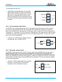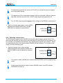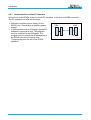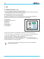
1
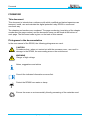
DIGITAL PROTECTION RELAY
User manual
DEBA N.V. - Moorstraat 24 - B-9850 Nevele - Belgium
+32 (0)9/371 75 51 - Fax +32 (0)9/371 59 25 - e-mail: [email protected]
- website: www.deba.biz
©2003 DEBA N.V.
All rights reserved.
The information provided may not be reproduced and/or published in any way or by any means (electronic or
mechanical), without the prior, explicit written authorisation of DEBA N.V.
The information provided is based on general data concerning the construction, material qualities and working methods
known at the time of publication, so that the right to make changes is reserved.
The information given is applicable to the standard version of the RP600. Therefore, DEBA N.V. cannot be held liable for
any damage resulting from specifications that differ from the standard version of the RP600.
The available information has been assembled with the greatest possible care but DEBA N.V. cannot be held liable for
any mistakes in the information or the consequences thereof.
In accordance with the legislation concerning the protection of trademarks, the user names, trade names, trade marks,
etc, used by DEBA N.V. cannot be considered to be free.
ii
RP600 Digital protection relay
Contents
CONTENTS
Contents.........................................................................................................iii
Foreword.........................................................................................................v
This document ............................................................................................................................v
Pictograms in the documentation ...............................................................................................v
Related documentation.............................................................................................................. vi
Service and technical support................................................................................................... vii
Identification of the RP600........................................................................................................ vii
General safety directions and instructions ............................................................................... viii
Intended use .............................................................................................................................. ix
1 General description.............................................................................. 1-1
1.1
1.1.1
1.1.2
1.1.3
1.1.3.1
1.1.3.2
1.1.4
1.1.5
1.1.6
1.1.7
1.1.8
1.1.9
1.1.10
1.1.10.1
1.1.10.2
1.1.10.3
1.1.10.4
1.1.11
Principle of operation .............................................................................................. 1-2
General ................................................................................................................... 1-2
Auxiliary power supply ............................................................................................ 1-3
Breaking characteristics.......................................................................................... 1-4
DTOC (absolute time overcurrent protection) ......................................................... 1-4
IDMT (inverse time overcurrent protection) ............................................................ 1-4
Phase currents of L1, L2, L3 and residual current of N .......................................... 1-6
Fault registration ..................................................................................................... 1-7
Incident registration................................................................................................. 1-7
Operational data registration................................................................................... 1-8
General break command ........................................................................................ 1-8
Self-diagnosis ......................................................................................................... 1-8
Signalling ................................................................................................................ 1-9
Detection of external faults ..................................................................................... 1-9
Detection of internal faults ...................................................................................... 1-9
Digital input ............................................................................................................. 1-9
Fault relays R1 and R2 ......................................................................................... 1-10
Operation of the RP600 ........................................................................................ 1-10
2 Technical specifications .....................................................................2-11
2.1
2.2
2.3
2.4
2.5
2.6
2.7
2.8
EMC tests ............................................................................................................. 2-11
Ambient conditions................................................................................................ 2-11
Inputs .................................................................................................................... 2-11
Outputs ................................................................................................................. 2-12
Parameter settings................................................................................................ 2-12
Measurement deviations....................................................................................... 2-12
Power supply ........................................................................................................ 2-12
Dimensions and weights ....................................................................................... 2-13
3 Transport and storage.......................................................................... 3-1
3.1
3.2
Safety instructions – transport ................................................................................ 3-1
Safety instructions – storage................................................................................... 3-1
4 Installation............................................................................................. 4-1
4.1
4.1.1
4.2
4.3
4.4
4.4.1
4.4.2
Safety instructions – installation.............................................................................. 4-1
General ................................................................................................................... 4-1
Unpacking ............................................................................................................... 4-2
Assembly ................................................................................................................ 4-2
Electrical connections ............................................................................................. 4-3
Connecting L1, L2, L3, N and N50.......................................................................... 4-3
Connecting an auxiliary power supply .................................................................... 4-4
Digital protection relay RP600
iii
Contents
4.4.3
4.4.4
4.4.5
4.4.6
4.4.7
Connecting fault relays R1 and R2 ......................................................................... 4-4
Connecting the digital input..................................................................................... 4-5
Detecting external faults ......................................................................................... 4-5
Detecting internal faults .......................................................................................... 4-6
Communication via the PC interface....................................................................... 4-7
5 Use ......................................................................................................... 5-1
5.1
5.2
5.2.1
5.3
5.3.1
5.3.1.1
5.3.1.2
5.3.1.3
5.3.1.4
5.3.1.5
5.3.2
5.3.2.1
5.3.2.2
5.3.2.3
5.3.2.4
5.3.2.5
5.4
5.5
5.5.1
5.5.2
5.5.2.1
Safety instructions – use......................................................................................... 5-1
Operating the local operating panel ........................................................................ 5-1
Menu structure ........................................................................................................ 5-3
Programming the RP600 ........................................................................................ 5-4
Programming via the local control panel................................................................. 5-4
Configuring fault relays R1 and R2 ......................................................................... 5-5
Configuring input IN1 .............................................................................................. 5-6
Selecting the language of the operating panel........................................................ 5-6
Setting the current ratio........................................................................................... 5-6
Setting the parameters............................................................................................ 5-7
Programming with the aid of the RP600 software................................................... 5-8
Data ........................................................................................................................ 5-9
General ................................................................................................................. 5-10
Line ....................................................................................................................... 5-10
Ground .................................................................................................................. 5-10
Breaking characteristics........................................................................................ 5-10
Reading current values ......................................................................................... 5-11
Reading fault information ...................................................................................... 5-12
Fault information from the LED indicators............................................................. 5-12
Fault information from the display......................................................................... 5-13
Reading the fault memory..................................................................................... 5-13
6 Maintenance.......................................................................................... 6-1
6.1
6.2
6.2.1
Safety instructions - maintenance........................................................................... 6-1
Maintenance - general ............................................................................................ 6-1
Cleaning the RP600................................................................................................ 6-1
7 Wiring diagram ..................................................................................... 7-1
8 The RP600 and the environment ......................................................... 8-1
8.1
8.2
Packing material ..................................................................................................... 8-1
Disposal of the RP600 ............................................................................................ 8-1
9 Fault finding .......................................................................................... 9-1
iv
Digital protection relay RP600
Foreword
FOREWORD
This document
This document is intended as a reference with which qualified and trained operators can
transport, install, use and maintain the digital protection relay RP600 in a safe and
economic way.
The chapters and sections are numbered. The page numbering (consisting of the chapter
number and the page number) and the document name can be found at the bottom of
each page. The document code is given on the back of this manual.
Pictograms in the documentation
In the user manual of the RP600, the following pictograms are used:
CAUTION
Procedures that - when not carried out with the necessary care - can result in
damage to the RP600, the surrounding area or the environment.
WARNING
Danger of high voltage
Notes, suggestions and advice
Consult the indicated information sources first.
Protect the RP600 from water or damp.
Ensure the reuse or environmentally friendly processing of the materials used.
Digital protection relay RP600
v
Foreword
Related documentation
The following related technical documentation is available for the RP600:
−
−
−
−
vi
Circuit breaker brochure. Ordering number: AG606302 (EN).
Digital protection relay RP600 folder. Ordering numbers: AG605102 (NL),
AG605202 (FR), AG605302 (EN).
User’s Manual for Circuit breaker VA-2 / VA-2RP. Ordering numbers: AG615102 (NL),
AG615202 (FR), AG615302 (EN), AG615402 (DE).
User Manual for Digital protection relay RP600. Ordering numbers: AG614102 (NL),
AG614202 (FR), AG614302 (EN), AG614402 (DE).
Digital protection relay RP600
Foreword
Service and technical support
For information concerning specific settings, maintenance or repair work that is not
mentioned here, please contact DEBA N.V.
• In this case, always mention the following data of the RP600:
−
serial number of the RP600
• Also, always mention the following data of the circuit breaker used:
−
type of circuit breaker
−
nominal voltage (see name plate on circuit breaker)
−
nominal current (see name plate on circuit breaker)
−
breaking capacity (see name plate on circuit breaker)
−
serial number of the circuit breaker
• See "Identification of the RP600".
Identification of the RP600
Each RP600 has a name plate with the serial number and the other technical data on the
back (fig. 0.01).
Name plate
• See fig. 0.01:
Digital protection relay RP600
vii
Foreword
General safety directions and instructions
DEBA N.V. does not accept any liability for damage or injury caused by not (strictly)
following the safety directions and instructions, or by negligence during the installation, the
use, the maintenance or the repair of the RP600 and any accompanying options.
Depending on the specific user circumstances or options fitted, extra safety instructions
may be necessary. Please contact DEBA N.V. immediately if you encounter a potential
danger when using the RP600.
The owner/manager of the RP600 is fully responsible at all times for following the
locally applicable safety regulations and guidelines.
User manual
• Everyone who uses or operates the RP600 must know the contents of the user manual
and follow the directions contained in it very closely. The owner/operator must teach the
users in accordance with the user manual and obey all directions and instructions.
• Never change the order of the actions to be taken.
• Always keep the user manual in the vicinity of the RP600.
Pictograms and safety symbols
Pictograms, symbols and instructions on the RP600 are part of the safety provisions.
Therefore, they may not be covered or removed and must be present and clearly readable
throughout the entire lifetime of the RP600.
• Replace or repair unreadable or damaged pictograms, symbols and instructions
immediately. For this purpose, contact DEBA N.V.
Operators
The performance of the work described (transport, installation, use and maintenance) is
strictly reserved for trained and qualified operators who are familiar with the dangers that
can occur when using the RP600. Temporary staff and personnel in training may not
operate the RP600 in any way.
Technical specifications
• The technical specifications may not be changed.
• Modification of (parts of) the RP600 is not permitted.
viii
Digital protection relay RP600
Foreword
Transport, storage, installation, use and maintenance
• See:
−
“Safety instructions – transport”
−
“Safety instructions – storage”
−
“Safety instructions – installation”
−
“Safety instructions – use”
−
“Safety instructions – maintenance”
Intended use
The RP600 is strictly designed to be used in combination with a circuit breaker, type VA–
2(RP) developed and produced by DEBA N.V. (or with a suitable circuit breaker from
another manufacturer) as an intelligent, automatic protection against thermal overloads
and short circuits in distribution and dispersion switchgears, transformers, generators and
electrical motors, in accordance with the specifications and conditions issued by DEBA
N.V. Any other or further use is not considered to conform to the intended use.
DEBA N.V. accepts no liability for any damage or injury resulting from such unauthorised
use.
The RP600 complies with the applicable standards and Guidelines.
• Only use the RP600 in technically perfect condition, in accordance with the intended
use described above.
Always keep sealed connections intact at all times. Breaking the sealed
connections irrevocably voids any claims under guarantee.
1
“Intended use” as laid down in EN 292-1 is the use for which the technical product is suited as specified by
the manufacturer-including his directions in the sales brochure. In case of doubt it is the use that can be
deduced from the construction, the model and the function of the technical product that is considered normal
use. Operating the product within the limits of its intended use also involves observing the instructions in the
user manual.
Digital protection relay RP600
ix
Foreword
x
Digital protection relay RP600
General description
1 GENERAL DESCRIPTION
The digital “self-powered” protection relay RP600 from DEBA N.V. has been designed as
an intelligent, automatic protection against thermal overloads and short circuits in
distribution and dispersion switchgears, transformers, generators and electrical motors.
The RP600 is used in combination with a circuit breaker, type VA–2(RP) from DEBA N.V.
(or with a suitable circuit breaker from another manufacturer).
By integrating the RP600 in your circuit breaker, the performance of your electrical
(protection) installation will be increased and the operating conditions will be safer. For this
purpose, the RP600 is fitted with high-quality communication and measurement functions.
All digital protection relays of the type RP600 fit in the DF-2 modular concept from DEBA
N.V.
A complete protection set consisting of a circuit breaker with an (integrated) RP600 is
characterised by the following main components:
A
B
C
D
E
F
Drive
Poles of L1, L2 and L3
Frame
Wheels
Digital protection relay RP600
Current transformers L1, L2 and L3
E
A
B
B
B
F
1
2
3
4
5
6
7
8
1
2
3
4
5
6
7
8
F
1
2
3
4
5
6
7
8
9
x
F
0
/
00
00
C
D
D
1.01
The current transformers can be placed both left and right of the poles of the
circuit breaker.
The RP600 is used to be able to switch the circuit breaker off automatically, on the basis of
the phase currents measured by the current transformers. The energy that is required to
switch the circuit breaker off comes from the tightened compression spring that is in the
mechanical drive of the circuit breaker. To be able to release the compression spring
automatically, the RP600 sends a signal to an electrical coil. When the electrical coil is
activated, the compression spring is indirectly released, via a mechanical link, and the
circuit breaker is switched off. For more information concerning the principle of operation
of the mechanical drive of the circuit breaker, see “Related documentation”.
Digital protection relay RP600
1-1
General description
1.1 Principle of operation
1.1.1 General
The digital protection relay RP600 serves for automatic protection with phase errors and
earth faults. On the RP600, the settings for both types of faults can be made separately. A
3-phase measurement can be made for each type of fault. The RP600 offers many
measurement and registration functions.
For the protection function of the RP600, a selection can be made from two different types
of breaking characteristics, see “Breaking characteristics”:
• Absolute-time breaking characteristic, one type:
• Constant
• Inverse-time breaking characteristic, subdivided into five different types:
• Inverse
• Very inverse
• Extremely inverse
• RXIDG (Long-lasting earth fault)
• RI inverse
Finally, the RP600 is fitted with the following supplementary functions:
•
•
•
•
Operational data registration, see “Operational data registration”
Fault registration, see “Fault registration”
Incident registration, see “Incident registration”
Self-diagnosis, see “Self-diagnosis”
The RP600 has connections for:
• Three measurement inputs to measure the current, see “Phase currents”
• One signal input that can be used to deactivate the measurement of the residual current
of N or that can be used to make a selection in the active parameter set, see
“Configuring input IN1”.
• Two switched outputs (fault relays), of which the function is freely configurable, see
“Configurable fault relays R1 and R2”.
• One signal output that, together with an extra output contact, can be used to detect
external faults, see “Detecting external faults”.
• One output contact that can be used to detect internal faults, see “Detecting internal
faults”.
• Auxiliary power supply of 110 or 230 VAC, to be able to use all programming functions
via the local operating panel, see “Auxiliary power supply”.
The following provisions are present for the operation of the RP600 and the indication of
(measurement) data:
• Local operating panel, provided with user-friendly user interface with clear display. The
RP600 is very easy and fast to program, as a result of its menu-oriented design, see
“Programming via local operating panel”.
1-2
Digital protection relay RP600
General description
• Serial PC interface to make all settings of the RP600 even more easily via a PC/laptop,
see “Programming with the aid of the RP600 software”. For this purpose, the software
(order number: RP601010) must first be installed on the PC/laptop.
• Eight LED indicators from which the status of the RP600 can be read, see “LED
indicators”.
1.1.2 Auxiliary power supply
The RP600 is “self-powered”. This means that the RP600 can function without an external
auxiliary power supply. The energy required for this is supplied by the three current
transformers. To make this possible, the (short circuit) current must satisfy the following
minimum conditions:
• For phase errors: = 0.4 Inominal
• For earth faults: = 0.2 Inominal
Under these circumstances, one can also:
• Read data from the memory and display it.
However, an auxiliary power supply is required for the following functionality:
• Setting the parameters via the local operating panel.
• Reading the status from the LED indicators.
The following possibilities can be used for the auxiliary power supply:
• 110 VAC
• 230 VAC
• PC connection cable with built-in battery
You can order a PC connection cable with built-in battery and a 110/230VAC auxiliary
power supply module from DEBA N.V.
See “Connecting an auxiliary power supply” for information about connecting an auxiliary
power supply to the RP600.
It is, however, recommended to always use an auxiliary power supply (even after the
installation has been put into operation). This “dual-powered operation” offers the following
advantages:
• The RP600 is also active with (short circuit) currents < 0.4 Inominal
• Shorter reaction time if the RP600 is active (30 ms instead of 40 ms)
• Detailed fault registration (of the last fault, including duration)
Without an auxiliary power supply, a minimum fault registration is performed:
• Storage in the memory of the cause of breaking
• Minimum fault registration
Digital protection relay RP600
1-3
General description
1.1.3 Breaking characteristics
For the assignment of the type of breaking characteristic to the RP600, a selection can be
made from two different types of breaking characteristics:
• DTOC (absolute time overcurrent protection)
• IDMT (inverse time overcurrent protection)
1.1.3.1 DTOC (absolute time overcurrent protection)
A protection via a DTOC characteristic (type: constant) is characterised by the following
(adjustable) parameters:
The following can be set for phases L1, L2 and L3:
• Current I> linked to time tI>
• Current I>> linked to time tI>>
The following can be set for the residual current of N:
• Current IN> linked to time tIN>
• Current IN>> linked to time tIN>>
1.1.3.2 IDMT (inverse time overcurrent protection)
A protection via an IDMT characteristic (types: inverse, very inverse, extremely inverse, RI
curve and RXIDG curve) is characterised by the following (adjustable) parameters:
The following can be set for phases L1, L2 and L3:
• Current Iref linked to inverse time characteristic
• Current I>> linked to time tI>>
The following can be set for the residual current of N:
• Current INref linked to inverse time characteristic or absolute time characteristic
• Current IN>> linked to time tIN>>
All inverse time characteristics that can be linked to Iref and INref satisfy the international
standards BS 142 and IEC 255-4. There now follows a summary of all breaking
characteristics.
1-4
Digital protection relay RP600
General description
• Constant
• Iref = 200A
• t = 1s
• Inverse
t =k∗
0.14
s
( I / Iref ) 0.02 − 1
• Iref = 200A
• k = 1 / 0.5 / 0.1
• Very inverse
t =k∗
13.5
s
( I / Iref ) − 1
• Iref = 200A
• k = 1 / 0.5 / 0.1
• Extremely inverse
t =k∗
80
s
( I / Iref ) 2 − 1
• Iref = 200A
• k = 1 / 0.5 / 0.1
Digital protection relay RP600
1-5
General description
• RI curve
t =k∗
1
0.236
0.339 −
( I / Iref )
s
• Iref = 100A
• k = 1 / 0.5 / 0.05
• RXIDG curve
t = 5.8 − 1.35 ∗ ln
I
s
(k * Iref )
• Iref = 100A
• k = 1 / 0.5 / 0.1
1.1.4 Phase currents of L1, L2, L3 and residual current of N
The standard version of the RP600 has four inputs for measuring the three phase currents
of L1, L2 and L3 and the residual current of N through the neutral conductor. The residual
current of N is continuously measured, but can be deactivated by using the signal input
“deactivate residual current measurement N”, see “Breaking residual current measurement
N”.
The integrated measurement circuit of the RP600, with which the size of each phase
current is measured, has an adjustable threshold value and an adjustable time delay for
each phase current. The deviation of the current is evaluated for each phase by using the
following formula:
Iasy =
IP , max − IP , min
∗ Inom
IP , max
The integrated measurement circuit for the phase currents can be configured in the
following ways:
• Evaluation of phases L1, L2 and L3
• No evaluation
1-6
Digital protection relay RP600
General description
1.1.5 Fault registration
When an external fault occurs, data concerning the character of the fault will be saved in
the “external fault memory”, see “Reading the external fault memory”. At the same time,
the LED indicators will indicate the character of the fault.
Detailed fault registration and reading the saved faults is only possible if an auxiliary power
supply (110 or 230 VAC) is used, see “Connecting an auxiliary power supply”.
If an auxiliary power supply is not used and the RP600 is no longer active, because the
phase currents < 0.4 Inominal, then, in case of a fault, only the following data is saved in the
(non-volatile) memory:
• LED indicator data
• Size of the fault current (with a maximum of 5 faults)
Besides information about external faults that have occurred, information is also saved on
internal faults of the RP600 that have occurred, see “Reading the internal fault memory”.
1.1.6 Incident registration
When an auxiliary power supply is used (see “Connecting an auxiliary power supply”), the
RP600 will separately count and register the following incidents:
• Size of the last fault current that occurred (also with more than 5 faults)
• Total duration of the last fault that occurred (for each phase)
The counters can be separately or collectively manually reset to zero. See “Reading
registered incidents” for user information.
Digital protection relay RP600
1-7
General description
1.1.7 Operational data registration
The RP600 measures, calculates and registers the following operational data:
• Maximum current values of the three phase currents of L1, L2 and L3
• Nominal current values of the three phase currents of L1, L2 and L3
• Nominal current value of the residual current of N
The operational data is determined every second. The current values are calculated as
r.m.s.-effective values, related to the nominal current of the RP600 (1A).
The operational data is always visible on the display, providing an auxiliary
power supply is used. If an auxiliary power supply is not used, the condition that
the RP600 is active (phase currents each ≥ 0.4 Inominal) must be satisfied.
1.1.8 General break command
If one or more of the following triggers become active, the RP600 will give a general break
command:
• tI>
• tI>>
• tIN>
• tIN>>
It is possible to switch specific triggers off by setting the time constant of the relevant curve
to infinity (99.99 s), see “Setting the parameters”.
To set the general break command, an auxiliary power supply must be used, see
“Connecting an auxiliary power supply”.
1.1.9 Self-diagnosis
The RP600 has extensive self-diagnostic tests that prevent hardware and software faults
from hindering the correct functioning of the RP600. The self-diagnostic tests are
continuously performed during the time that the RP600 is in operation. If one of the tests
faces a problem, the character of the fault that has occurred is displayed on the local
operating panel. Depending on the type of fault, the following actions are taken:
• The protection function of the RP600 is deactivated.
• A warning is given and the relay is de-energised.
All faults that have occurred are saved in a non-volatile memory, the “internal fault
memory”, see “Reading the internal fault memory”
1-8
Digital protection relay RP600
General description
1.1.10 Signalling
The RP600 makes it possible to signal external and internal faults. Furthermore, by using
the integrated fault relays R1 and R2, more specific external faults can be detected.
Moreover, it is possible to switch the residual current measurement of N off.
1.1.10.1 Detection of external faults
The RP600 has a signal output (OUT) and an output contact (ERR) that can be used to
detect external faults:
• Overcurrent on one of the phases L1, L2, L3 or N.
• Short circuit on one of the phases L1, L2, L3 or N.
When an external fault occurs, the signal output (OUT) and the output contact (ERR) will
be activated, see “Detecting external faults”.
1.1.10.2 Detection of internal faults
The RP600 has a signal output (WARN) that can be used to detect internal faults in the
hardware and software of the RP600:
• Memory fault
• Start-up fault
When an internal fault occurs, the output contact (WARN) will be activated, see “Detecting
internal faults”.
1.1.10.3 Digital input
The RP600 has a signal input (IN1), with which the measurement of the residual current of
N can be switched off, see “Configuring input IN1”. In the option menu, this input can be
configured as:
•
•
•
•
Normally on
Normally off
Not used (always on)
Not used (always off)
Alternatively, this input can also be used to select the active parameter set. Here also,
there are four possible options:
•
•
•
•
Normally on (set B if IN active, otherwise set A)
Normally on (set A if IN active, otherwise set B)
Always set A
Always set B
Digital protection relay RP600
1-9
General description
1.1.10.4 Fault relays R1 and R2
The RP600 is fitted with two fault relays (R1, R2) that are freely configurable. A choice can
be made between a normally open and a normally closed contact, see “Configuring fault
relays R1 and R2”. One of the following functions can be assigned:
Function
Niet gebruiktNot
used
Every fault
Overcurrent
Short circuit
Fault on L
Overcurrent on L
Short circuit on L
Fault on N
Overcurrent on N
Short circuit on N
Warning
Warning L
Warning N
Energisation of relay with
Relay is not energised
Every external fault
Overcurrent on the L and/or the N phases
Short circuit on the L and/or the N phases
Overcurrent/short circuit on the L phases
Overcurrent on the L phases
Short circuit on the L phases
Overcurrent/short circuit on the N phase
Overcurrent on the N phase
Short circuit on the N phase
Activation of L and/or N warning levels
Activation of L warning level
Activation of N warning level
1.1.11 Operation of the RP600
The operation of the RP600 is completely menu controlled and is performed through the
12 function keys of the local operating panel. The LCD display, consisting of two lines of
16 characters, gives instructions with which the menu can be run step by step.
The RP600 has eight LED indicators that provide visual information about the status of the
RP600. The function of all LEDs is indicated on the relevant label strip on the left side of
the LEDs.
By being built in, the RP600 can offer protection against unauthorised changes
of the settings by locking with a key or padlock.
For detailed information about the operation of the local operating panel, see “Use”.
All settings of the RP600 can also be configured with the aid of the RP600 software. This
software must be installed on a PC/laptop. For a complete description, see “Programming
with the aid of the RP600 software”.
1-10
Digital protection relay RP600
Technical specifications
2 TECHNICAL SPECIFICATIONS
2.1 EMC tests
• See the following table.
Specified item
Interference suppression
Value
According to:
IEC – EN 61000-4-2/3 (level 3)
IEC – EN 61000-4-4/5/6/12IEC – EN 61000-44/5/6/12
• Casing 30 MHz – 230 MHz,
40 dB(µV/m) quasi peak at 10 m.
• Casing 230 MHz – 1000 MHz,
47 dB(µV/m) quasi peak at 10 m.
• Power supply voltage 0.15 MHz – 0.50 MHz,
79 dB(µV) quasi peak, 66 dB(µV) average.
• Power supply voltage 0.50 MHz -30 MHz,
73 dB(µV) quasi peak, 60 dB(µV) average.
Emission
2.2 Ambient conditions
• See the following table.
Specified item
Ambient temperature
Storage temperature
Relative air humidity
Value
-10 °C – +55 °C
-20 °C – +60 °C
According to: CEI 68-2-30
2.3 Inputs
• See the following table.
Specified item
Measurement inputs
(L1/L2/L3)
Value
INom = 1A, IMax = 3 x INom INom = 1.00A
IMax = 1.25A (continuous)
IMax = 2.00A (for 1 minute)
IMax = 20.00A (for 1 second)
Signal input (IN1)
12 VDC ± 10%
Digital protection relay RP600
2-11
Technical specifications
2.4 Outputs
• See the following table.
Specified item
Output contacts
Output contact ERR
Other output contacts
Value
• Maximum load = 30 W
• 8A / 230V
• 8A / 230V
2.5 Parameter settings
• See “Setting the parameters”.
2.6 Measurement deviations
• See the following table.
Specified item
Measurement accuracy
current (I) and time (t) with 50 Hz
Value
5%
(7.5% for RI curve)
2.7 Power supply
• See the following table.
Specified item
Auxiliary power supply (A1/A2)
Auxiliary power supply (DB9)
2-12
Value
115/230 VAC (50/60 Hz)
12 – 36 VDC (max. 100 mA)
Digital protection relay RP600
Technical specifications
2.8 Dimensions and weights
9,4 cm
2,5
8,5 cm
22 cm
8 cm
Warning 1
Shutdown 2
3
4
5
Line 3
6
Neutral
Magnetic 7
Thermic 8
Line 1
Line 2
1
2
3
4
5
6
7
8
9
17 cm
0
RP 600
2.01
Digital protection relay RP600
2-13
Technical specifications
2-14
Digital protection relay RP600
Transport and storage
3 TRANSPORT AND STORAGE
3.1 Safety instructions – transport
Protect the RP600 against water and other liquids.
An RP600 that is seriously damaged during transport must at all times be
returned to DEBA N.V. for inspection before the RP600 is put into operation.
3.2 Safety instructions – storage
• See also “General safety directions and instructions”.
• Respect the ambient conditions. See "Ambient conditions".
• Keep the RP600 in a dry, dust free area.
Digital protection relay RP600
3-1
Transport and storage
3-2
Digital protection relay RP600
Installation
4 INSTALLATION
4.1 Safety instructions – installation
4.1.1 General
Installation of the RP600 is restricted to qualified and trained operators with
observance of the locally applicable safety instructions and guidelines.
This is a product of class A. If this equipment is used in a domestic environment,
radio disturbance can occur. When this problem occurs, it can be necessary that
it is solved by the user.
• See also “General safety directions and instructions”.
• Never leave tools or fastening material in or on top of the RP600.
• Use the RP600 exclusively with a suitable circuit breaker, type VA–2(RP) developed
and produced by DEBA N.V. (or with a suitable circuit breaker from another
manufacturer).
• Install the RP600 only in areas that fully meet the recommendations (according to IEC
60694), such as those that also apply to the appropriate circuit breaker, see the manual
of the relevant circuit breaker.
Digital protection relay RP600
4-1
Installation
4.2 Unpacking
The most suitable place for unpacking the RP600 is the definitive installation area.
If parts are missing or damaged, contact the forwarder or DEBA N.V. A seriously
damaged RP600 must always be returned to DEBA N.V.
After the packaging material used has been removed in accordance with
prevailing legislation, the assembly of the RP600 can be started.
4.3 Assembly
The RP600 consists of an aluminium housing. The RP600 can be used for wall assembly
and building in. In both cases, the unit is fastened with the aid of suitable fastening
material. In the sides of the RP600, there are four threaded holes left and right. In each of
the sides, two screws are fitted diagonally as standard. They keep the sides in place. The
two free holes per side are used to mount the RP600 with screws (A) on support plates (B)
if the RP600 is built into the VA-2 circuit breaker.
order number
Description
quantity item no.
GR043809
Cheese head sheet metal screw with cross
recess
4
fig. 4.00 A
3
2
6
1
5
4
9
8
7
0
X
B
A
4.00
4-2
Digital protection relay RP600
Installation
4.4 Electrical connections
The RP600 is fitted with two terminal blocks A and B. These are used to make connections
for the currents to be measured, the signal inputs, the signal outputs, the output contacts,
fault relays R1 and R2 and the external auxiliary power of the RP600.
Reserved for later
extension.
See “Connecting L1,
L2, L3, N and N50”.
See "Detecting
external faults"
Reserved for later
extension.
See "Connecting an
auxiliary power
supply".
[VAC meas+]
[N50/VAC meas-]
N
L3
L2
L1
OUT-(0 V)
OUT+(12 V)
[110 VDC-]
[110 VDC+]
110/230 VAC
110/230 VAC
A
12
11
10
9
8
7
6
5
4
3
2
1
B
12
R2 (com)
11
R2 (NO)
10
R2 (NC)
See “Connecting fault
relays R1 and R2”.
9
R1 (com)
8
R1 (NO)
7
R1 (NC)
6
ERR (com) See "Detecting
5
ERR (NO) external faults"
4 WARN (com) See "Detecting internal
3 WARN (NO) faults"
2
IN1+
See "Configuring input
IN1".
1
IN1-
4.4.1 Connecting L1, L2, L3, N and N50
Five terminals are reserved on terminal block A for the connection of phase currents L1,
L2 and L3, and residual currents N and N50 (A7, A8, A9, A10 and A11, respectively). With
a current ratio of 1:50 in the current transformers used:
•
Connect phase currents L1, L2 and L3 and
residual currents N and N50 as follows:
A
N50
11
N50
N
10
N
L3
9
L3
L2
8
L2
L1
7
L1
4.01
Digital protection relay RP600
4-3
Installation
4.4.2 Connecting an auxiliary power supply
Two terminals (A1 and A2) are reserved on terminal block A for the connection of an
auxiliary power supply, see also “Auxiliary power supply”. It is possible to use both 230
VAC and 110 VAC on terminals A1/A2.
•
Connect 110 VAC or 230 VAC between
terminals A1 and A2.
A
2
110/230 Vac
1
110/230 Vac
110/230Vac
4.02
•
If there is no local 110 VAC or 230 VAC
present, you can use a serial PC connection
cable with built-in battery. There is a DB9
connector at the front of the RP600 for this
purpose. Connect the cable between the
serial COM port of your PC/laptop and the
DB9 connector on the RP600.
DB9
DB9
PC
RP-600
4.03
4.4.3 Connecting fault relays R1 and R2
The RP600 has two fault relays R1 and R2. The function of these relays can be
configured, see "Configuring fault relays R1 and R2". Five terminals are reserved on
terminal block B of the RP600 for both relays (B7, B8, B9 and B10, B11, B12,
respectively). A normally open (NO) and a normally closed (NC) contact are available for
both R1 and R2. When the assigned function becomes active, the relevant output contact
(R1, R2) will be activated. For the use of this output, see the following figures.
Connecting fault relay R1:
•
Depending on requirements, the normally
open output contact (R1 (NO)) on terminal
(B8) or the normally closed output contact
(R1 (NC)) on terminal (B7) can be used.
When the assigned function becomes active,
the NO contact will close and the NC contact
will open.
B
R1(COM)
9
R1(NO)
8
R1(NC)
7
4.04
4-4
Digital protection relay RP600
Installation
Connecting fault relay R2:
•
Depending on requirements, the normally
open output contact (R2 (NO)) on terminal
(B11) or the normally closed output contact
(R2 (NC)) on terminal (B10) can be used.
When the assigned function becomes active,
the NO contact will close and the NC contact
will open.
B
R2(COM)
12
R2(NO)
11
R2(NC)
10
4.05
4.4.4 Connecting the digital input
The RP600 has a digital signal input (IN1), with which the measurement of the residual
current of N can be switched off. Two terminals (B1 and B2) are reserved on terminal
block B of the RP600 for this purpose. In the option menu, input IN1 can be configured as
“Normally on”, “Normally off” or as “Not used”. Alternatively, this input can be used to make
a selection from the active parameter set, see "Configuring input IN1". For the use of this
input, see the following figure.
•
Connect a 12 VDC signal voltage between
terminals B1 (IN1-) and B2 (IN1+).
B
IN1(+)
2
+
12 Vdc
IN1(-)
1
4.06
4.4.5 Detecting external faults
The RP600 has a signal output (OUT) and an output contact (ERR) that can be used to
detect external faults. Four terminals are reserved on terminal blocks A and B of the
RP600 for this purpose (resp. A5, A6 en B5, B6). For an overview of all possible external
faults, see "Reading the external fault memory". When an external fault occurs, the signal
output (OUT) and the output contact (ERR) will be activated. For the use of these outputs,
see the following figure.
•
Use the 12 VDC output signal on terminals
A5 (OUT+) and A6 (OUT-) for the drive
(release) of the compression spring.
A
0V 12V
+
6
OUT-(0V)
5
OUT+(12V)
4.07
Digital protection relay RP600
4-5
Installation
The switching signal will be active for 30 to 35 ms, so that the drive can tighten
the compression spring.
The tightening of the compression spring in the circuit breaker, after an external
fault has occurred, results in the 12 VDC output signal being switched off.
The 12 VDC output signal disappears if the voltage of the RP600 is switched off.
•
Use the normally open output contact (ERR)
between terminals B6 (ERR com) and B5
(ERR NO) to indicate an external fault.
B
ERR(COM)
6
ERR(NO)
5
4.08
4.4.6 Detecting internal faults
The RP600 has a signal output (WARN) that can be used to detect internal faults. Two
terminals (B3 and B4) are reserved on terminal block B of the RP600 for this purpose. For
an overview of all possible internal faults, see "Reading the internal fault memory". When
an internal fault occurs, the output contact (WARN) will be activated. For the use of this
output, see the following figure.
•
Use the normally open output contact
(WARN) between terminals B3 (WARN NO)
and B4 (WARN com) to indicate an external
fault.
B
WARN(COM)
4
WARN(NO)
3
4.09
The output contact (WARN) also closes when the RP600 is set to programming
mode.
At the same time that the output contact (WARN) closes, the LED indicator
WARNING will light up.
4-6
Digital protection relay RP600
Installation
4.4.7 Communication via the PC interface
On the front of the RP600, there is a serial PC interface, in the form of a DB9 connector.
The PC interface can fulfil two functions:
• Alternative auxiliary power supply for the
RP600, see "Connecting an auxiliary power
supply".
• Communication with a PC/laptop. Special PC
software is required for this. The program
must be installed on the PC/laptop. The
program can be used to set all parameters in
the RP600 from the PC/laptop, see
"Programming with the aid of the RP600
software".
DB9
DB9
PC
RP-600
Digital protection relay RP600
4.10
4-7
Installation
4-8
Digital protection relay RP600
Use
5 USE
5.1 Safety instructions – use
• See also “General safety directions and instructions”.
• Use of the RP600 is restricted to qualified and trained operators, while observing the
locally applicable safety instructions and guidelines.
5.2 Operating the local operating panel
The RP600 is operated with the local operating panel on the front of the RP600. The
following controls, function keys and indicators can be distinguished:
A
B
C
D
LCD display
Numeric function keys 0 - 9
Escape key
Enter key ↙
F
A
Warning 1
Shutdown 2
3
4
5
6
Neutral
Magnetic 7
Thermic 8
Line 1
Line 2
E Arrow keys ←,↑,→,↓
F LED indicators
G PC interface
Line 3
1
2
3
4
5
6
7
8
9
0
RP 600
E, B
D
C
G
5.01
The menu-driven operation of the RP600 is easy and is performed step by step:
1. Use the arrow keys to run through all menus. A menu can be run through with arrow
keys ↑ and ↓. With arrow keys ← and →, you can jump between menus.
2. Use the arrow keys to select the desired menu item.
3. Press the Enter key ↙ to be able to change the value of the selected menu item.
4. Press the numeric keys 0 – 9 or the arrow keys ← , ↑,→,↓ to enter the desired value.
5. Press the Enter key ↙ to save the value.
As long as the value has not been saved, the action can be cancelled by
pressing the Escape key ×.
Digital protection relay RP600
5-1
Use
Menus marked by “
“ cannot be run through without an auxiliary power
supply. Menus marked by “
“ can be run through without an auxiliary power
supply.
To actually be able to change and save a value, this must first be made possible.
Select “Programming” in the “Options” menu and change the value to “active”.
As a result, the RP600 will be made inactive and the “warning” LED will light up.
By pressing the Escape key ×, you can jump from any menu to a menu at a
higher level.
If the operating panel is not used for 20 seconds, the program automatically
jumps back to the main screen, in which the size of the four currents (L1, L2, L3
and N) is displayed, see “Reading current values”.
For some menu items, the Enter key ↙ must be pressed twice to save the
change. This concerns the following menu items: “Delete faults” and “Default
values”. By pressing the Escape key ×, the action can be cancelled.
When the RP600 leaves the factory, all parameters are set to default values. It is
always possible to return to these default values. Select “Default values” in the
“Options” menu and change the value to “set”.
5-2
Digital protection relay RP600
Use
5.2.1 Menu structure
Look at currents
Current of L1
Current of L2
Current of L3
Current of N
L Current (Th)
L Time (Th)
Parameters A / B
L Curve
L Current Factor
L Time Factor
N Current (Th)
N Time (Th)
N Curve
N Current Factor
N Time Factor
L Current (Magn)
L Time (Magn)
Magnetic
N Current (Magn)
N Current (Magn)
Warning level
L Current
N Current
Fault currents
Internal fault
Fault current of L1
Fault current of L2
Fault current of L3
Fault current of N
Options
Delete Faults
Delete maximums
Program
Curves:
Language
Error relay 1
constant
Error relay 2
inverse
Ignore N errors
very inverse
Parameter set A/B
extremely inverse
Ratio
RI curve
Default values
RXIDG curve
With aux. power supply
Without aux. power supply
Digital protection relay RP600
5-3
Use
5.3 Programming the RP600
5.3.1 Programming via the local control panel
When the RP600 leaves the factory, all parameters are set to default values. It is
always possible to return to these default values. Select “Default values” in the
“Options” menu and change the value to “set”.
With the menu-driven operation, the RP600 is easy to program, see “Menu structure”.
Follow the following recommended sequence when programming:
1. Connect an external auxiliary power supply to be able to program the RP600 fully, see
“Connecting an auxiliary power supply”.
2. Prepare the RP600 so that it can be programmed. Select “Programming” in the
“Options” menu. Press the Enter key ↙ so that the value is changed to “active”.
A parameter can be changed if the text “Ep” (Edit parameter) is shown at the
bottom left in the display. At the same time, the parameter value will flash.
Change the value with the numeric function keys and/or the arrow keys. Press
the Enter key ↙ to save the parameter value or press the Escape key × to
interrupt the action, see “Operating the local operating panel”.
As long as “Programming” has the value “not active”, no changes in value will be
accepted.
The protection function and the measurement functions of the RP600 are made
inactive when the programming function becomes active. As an indication, the
LED “WARNING” will light up and the output contact (WARN) will be activated.
3. Select the desired language. Select “Language” in the “Options” menu. Go to the
desired language (“English”, “Nederlands”, “Français”) and press the Enter key ↙ ,see
also “Selecting the language”.
4. Set the current ratio of the current transformers used. Select “Ratio” in the “Options”
menu. Press the Enter key ↙ to change the value. Enter the correct value (“1:50”,
“1:150”, “1:200”, “1:400”, “1:600”). Press the Enter key ↙ again to save the value, see
also “Setting the current ratio”.
5. Set the desired parameters for the L Curve, N Curve and Magnetic. Select the desired
characteristic (“constant”, “inverse”, “very inverse”, “extremely inverse”, “RI curve”,
“RXIDG curve”) for the L and N Curves. Set the graph. Four variables (“Current (Th)”,
“Time (Th)”, “Current Factor”, “Time Factor”) must be set for each graph. Set the correct
value for each variable, see also “Setting the parameters”.
5-4
Digital protection relay RP600
Use
6. Exit the programming. Select “Programming” in the “Options” menu. Press the Enter key
↙ so that the value is changed to “not active”. The protection function and the
measurement functions of the RP600 are reactived. As an indication, the LED
“WARNING” will go out.
5.3.1.1 Configuring fault relays R1 and R2
Configure the functions of fault relays R1 and R2 as follows:
Select “Fault relay 1” or “Fault relay 2” in the “Options” menu and select the desired value.
Press the Enter key ↙ to be able to change the value and press the Enter key ↙ again to
save the configuration.
Parameter to be set
Fault relays 1 and 2
Content of LCD
display
Fault relays 1 / 2
Value
Possible Values
Not used
Default Value
Not used
Every fault
Overcurrent
Short circuit current
Fault on L
Overcurrent on L
Short circuit on L
Fault on N
Overcurrent on N
Short circuit on N
Warning
Warning L
Warning N
Digital protection relay RP600
5-5
Use
5.3.1.2 Configuring input IN1
Configure the function of digital input IN1 as follows:
Select “Ignore N faults” or “Parameter set A/B” in the “Options” menu and select the
desired value. Press the Enter key ↙ to be able to change the value and press the Enter
key ↙ again to save the configuration.
Parameter to be set
Ignore N faults
Content of LCD
display
Ignore N faults
Value
Possible Values
Default Value
Do not ignore
Do not ignore
If IN1 is on
If IN1 is off
Always ignore
Parameter set A/B
Parameter set A/B
Value
Only set A
Only set A
Only set B
B if IN1 is on*
B if IN1 is off*
(*) If IN1 is active, parameter set B is selected, otherwise parameter set A.
(**) If IN1 is inactive, parameter set B is selected, otherwise parameter set A.
5.3.1.3 Selecting the language of the operating panel
Select the language of the operating panel as follows:
Select “Language” in the “Options” menu and select the desired value. Press the Enter key
↙ to change the value.
Parameter to be set
Language
Content of LCD
display
Language
Value
Possible Values
English
Default Value
English
Nederlands
Français
5.3.1.4 Setting the current ratio
Set the current ratio to suit the current transformers used. Select “Ratio” in the “Options”
menu. Press the Enter key ↙ to change the value. Enter the correct value. Press the Enter
key ↙ again to save the value.
5-6
Digital protection relay RP600
Use
Parameter to be set
Current ratio
Content of LCD
display
Ratio
Value
Possible Values
Default Value
1 : 50
1 : 50
1 : 150
1 : 200
1 : 400
1 : 600
5.3.1.5 Setting the parameters
The parameters of the RP600 with regard to the L curve, N curve and magnetic can be set
as follows. Set parameters of L curve:
Select “L curve”, “N curve” or “Magnetic” in the “Parameters” menu. Select the relevant
parameter of which the value must be set. Press the Enter key ↙ to be able to change the
value and press the Enter key ↙ again to save the changed value. Do this for all
parameters that need setting.
When the RP600 leaves the factory, all parameters are set to default values. It is
always possible to return to these default values. Select “Default values” in the
“Options” menu and change the value to “set”.
Parameter to be set
Content of LCD
display
Minimum
Value
Maximum
Value
Default
Value
Value
see “Menu
structure”
see “Menu
structure”
Constant
Value
0.40 In
2.50 In
1.00 In
Value
0.00 s
99.98 s / ∞
1.00 s
L Current Factor
Value
0.40 In
2.50 In
1.00 In
L-K Factor
L Time Factor
Value
0.05
1.00
1.00
N Curve
N Curve
Value
see “Menu
structure”
see “Menu
structure”
Constant
N Thermal Current
N Current (Th)
Value
0.20 In
2.50 In
0.80 In
N Thermal Time
N Time (Th)
Value
0.00 s
99.98 s / ∞
1.00 s
0.20 In
2.50 In
0.80 In
L Curve
L Curve
L Thermal Current
L Current (Th)
L Thermal Time
L Time (Th)
L Factor
L warning
Critical current L
Value
Digital protection relay RP600
5-7
Use
Parameter to be set
Content of LCD
display
Minimum
Value
Maximum
Value
Default
Value
N warning
Critical current N
Value
0.10 In
2.50 In
0.60 In
N Factor
N Current Factor
Value
0.02 A
0.80 A
0.02 A
N-K Factor
N Time Factor
0.05
1.00
1.00
L Current Magnetic
L Current (Magn)
Value
0.40 In
12.00 In
4.00 In
L Time Magnetic
L Time (Magn)
0.00 s
99.98 s / ∞
0.50 s
N Current Magnetic
N Current (Magn)
Value
0.40 In
7.50 In / ∞
∞ In
N Time Magnetic
N Current (Magn)
Value
0.00 s
99.98 s / ∞
0.50 s
Value
Value
5.3.2 Programming with the aid of the RP600 software
The RP600 can also be programmed with the aid of the RP600 software supplied. The
RP600 software must be installed on a PC/laptop and communicates with the RP600 via a
serial PC interface, see “Communication via PC interface”. The following settings can be
made:
• Language
• Current ratio
• Functions of fault relays R1 and R2
• L curve parameters for set A (and possibly for set B)
• N curve parameters for set A (and possibly for set B)
5-8
Digital protection relay RP600
Use
The screen is divided into five parts:
• Data
• General
• Line
• Ground
• Breaking characteristics
With the help of eight available parameter sets (tab sheets), just as many different RP600
configurations can be set and compared with each other.
5.3.2.1 Data
Button
Save file
Read file
Save all data
Delete all data
Write to RP600
Read the RP600
RP600 Faults
Function
Saves the selected parameter set in a file.
Loads the data from a file. If this file contains one parameter set,
this data is included in the selected parameter set. If this file
contains several parameter sets, all existing parameter sets are
overwritten.
Saves all eight parameter sets in a file.
Deletes the data of all eight parameter sets.
Opens the COM port and writes the data from the selected
parameter set to the RP600.
Opens the COM port, reads the data of the RP600 and overwrites
the selected parameter set.
Opens the COM port and reads the last fault values. Faults can
also be deleted.
Digital protection relay RP600
5-9
Use
5.3.2.2 General
Button
Language
Transfo
Relay 1
Relay 2
Measure N
Param-set
Function
Selecting the desired language.
Sets the current ratio.
Sets the function of fault relay 1.
Sets the current ratio.
When the checking of earth fault is active (instead of IN1).
Determines which parameter set is active (A or B).
5.3.2.3 Line
Button
Type
Current
Time
Current (Magn)
Time (Magn)
Warning
Function
Sets the type of breaking characteristics for L phase currents.
Sets the thermal current for the L phase currents.
Sets the breaking time for the L phase currents.
Sets the current for the L phase currents (magnetic).
Sets the breaking time for the L phase currents (magnetic).
Level at which a warning fault can be given on R1 or R2.
5.3.2.4 Ground
Button
Type
Current
Time
Current (Magn)
Time (Magn)
Warning
Function
Sets the type of breaking characteristics for N residual current.
Sets the thermal current for the N residual current.
Sets the breaking time for the N residual current.
Sets the current for the N residual current (magnetic).
Sets the breaking time for the N residual current (magnetic).
Level at which a warning fault can be given on R1 or R2.
5.3.2.5 Breaking characteristics
The top characteristic shows all settings for the L phase currents graphically. The bottom
characteristic shows all settings for the N residual current graphically. Each parameter set
is identified by means of a unique colour:
Parameter set
1
2
3
4
Colour
Brown
Red
Orange
Yellow
Parameter set
5
6
7
8
Colour
Green
Blue
Purple
Grey
On the basis of the different colours, it is possible to compare different parameter sets with
each other. Each line is a combination of the thermal and the magnetic settings.
5-10
Digital protection relay RP600
Use
5.4 Reading current values
The size of the current values of the three phase currents of L1, L2 and L3 and the
residual current of N can be read from the display. Select “Look at currents” in the main
menu. Select the desired current and press the Enter key ↙ to look at the current value.
The display could look as follows for the respective currents (the maximum measured
current value is given between brackets):
Current of L1
125 A
( 160 A
)
Current of L2
130 A
( 158 A
)
Current of L3
128 A
( 155 A
)
Current of N
1A
(3A )
The maximum measured current value that is given between brackets can be
reset to zero at all times. Select “Delete maxima” in the “Options” menu. Press
the Enter key ↙ to reset all maximum measured current values to zero.
If the operating panel is not used for 20 seconds, the program automatically jumps back to
the main screen, in which the size of the four currents (L1, L2, L3 and N) is displayed in
amps. The display could look as follows:
1= 125
3= 128
2= 130
N=
1
Digital protection relay RP600
5-11
Use
5.5 Reading fault information
Information about the status of the RP600 can be read in two ways:
• From the LED indicators, see “Fault information from the LED indicators”
• From the display, see “Fault information from the display”
Fault information from the LED indicators is combined with supplementary information that
is visible on the display.
5.5.1 Fault information from the LED indicators
The function of all LED indicators is fixed. If the assigned function of a certain LED
indicator becomes active, because a fault occurs in the field, the corresponding indicator
will light red continuously, under the condition that an auxiliary power supply is used, see
“Connecting an auxiliary power supply”. Supplementary information about the size of the
fault current can be read on the display.
LED
indicator
WARNING
ERROR
L1
L2
L3
N
MAGNETIC
THERMIC
Meaning
Warning. The RP600 is not operational, because the programming
function is active or because there is an internal fault. The corresponding
output contact (WARN) is closed, see “Detecting internal faults”.
The RP600 has detected a fault current. More information can be read on
the remaining LED indicators. The corresponding output contact (ERR)
was short circuit, see “Detecting external faults”.
Fault on L1
Fault on L2
Fault on L3
Fault on N
Short circuit current
Overcurrent
Each new external fault will re-initialise the fault information of the LED
indicators.
5-12
Digital protection relay RP600
Use
5.5.2 Fault information from the display
Information about the fault can be read on the display. There can be an external or an
internal fault. Information about the faults is saved in:
•
•
The external fault memory, see "Reading the external fault memory"
The internal fault memory, see "Reading the internal fault memory"
Besides information about faults, information is also saved on incidents that have
occurred. Incidents can also be read on the display, see "Reading registered incidents”.
5.5.2.1 Reading the fault memory
When an external fault occurs, the LED indicators will display the character of the external
fault. The latest (most recent) external fault is saved in the “external fault memory”.
Specific information about the external fault (size and duration of the fault current) can be
read on the LCD display. Examples of possible reports that can occur with the various
external faults are:
External fault
Content of LCD
display
Internal fault
Internal fault
Overcurrent/short circuit L1
Fault current of L1
150 A
(99.99s)
Overcurrent/short circuit L2
Fault current of L2
0A
(0.00s)
Overcurrent/short circuit L3
Fault current of L3
0A
(0.00s)
Overcurrent/short circuit N
Fault current of N
0A
(0.00s)
(*)
The “external fault memory” can be reset as follows. Select “Delete faults” in the
“Options” menu and press the Enter key ↙ twice.
Information about the fault currents is deleted from the external fault memory if
there is no external auxiliary power supply present or if it is interrupted.
(*) With an internal fault, the following reports are possible:
• “No fault”, the RP600 is OK.
• “Memory fault”, the memory of the RP600 has become corrupted. Return the RP600
to DEBA N.V. for reprogramming.
• “Parameters invalid”, one or more parameters are invalid. Check all
parameters and
restore invalid parameters. Use the operating panel or the PC (with RP600 software) for
this. You can also use the option menu to return to the default values. If the fault
persists, return the RP600 to DEBA N.V. for reprogramming.
Digital protection relay RP600
5-13
Use
5-14
Digital protection relay RP600
Maintenance
6 MAINTENANCE
6.1 Safety instructions - maintenance
• See also “General safety directions and instructions”.
• The maintenance actions described are restricted to qualified and trained operators only
while observing the locally applicable safety instructions and guidelines.
• All other maintenance actions not described are restricted to trained and authorised
service personnel.
• Ensure that the RP600 is voltage free before you carry out the maintenance actions
described.
• Only put the RP600 back into operation after the maintenance actions have been
accurately verified.
• Never leave tools or fastening material in or on top of the RP600.
6.2 Maintenance - general
The RP600 has been designed to operate problem free with a minimum of maintenance.
6.2.1 Cleaning the RP600
Contamination of the RP600 can initially be limited by following the IEC
recommendations concerning the installation area. See “Recommendations installation area”.
Adhere to the following steps when cleaning the RP600:
• Read the safety instructions first. See “Safety instructions – maintenance”
• Clean the outside with a non-fluffy cloth and a non-corrosive cleaning agent.
• Rub the cleaned surfaces thoroughly dry.
Digital protection relay RP600
6-1
Maintenance
6-2
Digital protection relay RP600
Wiring diagram
7 WIRING DIAGRAM
A
B
12
R2
11
N
10
L3
9
L2
8
L1
7
VA
230V
R1
5
0V
2
1
9
8
7
12V
3
11
10
6
4
12
ERR
WARN
IN1
6
5
4
3
2
IN1+ (12V)
1
IN1- (0V)
7.01
Digital protection relay RP600
7-1
Wiring diagram
7-2
Digital protection relay RP600
The RP600 and the environment
8 THE RP600 AND THE ENVIRONMENT
8.1 Packing material
The packing material mainly consists of:
−
cardboard
−
plastic film
• Contact the local public cleansing department for the details of recycling or an
environmentally friendly way of processing the packing materials.
• Tender the packing material as instructed (separated).
8.2 Disposal of the RP600
In the framework of the reuse of electrical components, the RP600 can be returned to
DEBA N.V. at the end of its lifetime (or earlier in the case of damage).
On consultation, the complete RP600 can also be returned. If this is not possible, the
RP600 must be processed in an environmentally friendly way.
Contact the local public cleansing department and tender the material in the
prescribed manner (separated).
Digital protection relay RP600
8-1
The RP600 and the environment
8-2
Digital protection relay RP600
Fault finding
9 FAULT FINDING
When the RP600 is not functioning (correctly), do not try to fix the problem yourself.
• Contact DEBA N.V. or call in the help of trained and authorised service personnel.
Digital protection relay RP600
9-1
Fault finding
9-2
Digital protection relay RP600
AG614102
©2003 DEBA N.V.