1
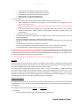
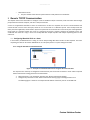
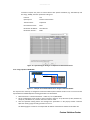
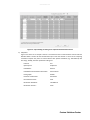
www.infoPLC.net Custom Solutions Center Quick Start Guide Ethernet Communication With Mitsubishi Q PLCs Version 1.0 www.infoPLC.net Content 1 Introduction ......................................................................................................................................................................... 1 2 Mitsubishi Ethernet Communication Configuration ............................................................................................................ 1 2.1 2.1.1. Ethernet Front Port ................................................................................................................................................ 1 2.1.2. QJ71E71-100 Module ............................................................................................................................................. 2 2.2 3 Ethernet Front Port ................................................................................................................................................ 5 2.2.2. QJ71E71-100 Module ............................................................................................................................................. 8 Generic TCP/IP Communication......................................................................................................................................... 12 Configuring Mitsubishi PLC as a Sever...................................................................................................................... 12 3.1.1. Using the PLC Built-In Front Ethernet Port .......................................................................................................... 12 3.1.2. Using a QJ71E71-100 Module .............................................................................................................................. 14 3.2 Configuring Mitsubishi PLC as a Client ..................................................................................................................... 17 3.2.1. Using the PLC Built-In Front Ethernet Port .......................................................................................................... 17 3.2.2. Using a QJ71E71-100 Module .............................................................................................................................. 19 MC Protocol Communication ............................................................................................................................................. 20 4.1 Configuring Mitsubishi PLC as a MC Protocol Sever ................................................................................................. 21 4.1.1. Using the PLC Built-In Front Ethernet Port .......................................................................................................... 21 4.1.2. Using a QJ71E71-100 Module .............................................................................................................................. 22 4.2 5 Open Setting ............................................................................................................................................................... 5 2.2.1. 3.1 4 Operation Setting ....................................................................................................................................................... 1 Configuring Mitsubishi PLC as a Client ..................................................................................................................... 24 4.2.1. Using the PLC Built-In Front Ethernet Port .......................................................................................................... 24 4.2.2. Using a QJ71E71-100 Module .............................................................................................................................. 26 Appendix: Example ............................................................................................................................................................ 29 Custom Solutions Center www.infoPLC.net FURTHER READING REFERENCE LIST ( Mitsubishi Q Corresponding MELSEC Communication Protocol Reference Manual SH(NA)-080008-K QnUCPU User’s Manual Communication via Built-in Ethernet Port SH(NA)-080811ENG-D Q Corresponding Ethernet Interface Module User’s Manual (Basic) SH (NA)-080009-O (1008)MEE MEAU Custom Solutions Center – Ethernet TCP Communication FBs Quick Start Guide V1.0 MEAU Custom Solutions Center – Ethernet MC Protocol Communication FBs Quick Start Guide V0.2 Custom Solutions Center www.infoPLC.net Document Management Information Date November 2, 2011 Version No. 1.0 Document Name Q_ENET_Comm Revision Initial Release Revised By MEAU Custom Solutions Center Custom Solutions Center www.infoPLC.net 1 Introduction The purpose of this document is to describe the basic steps that are required to configure a Mitsubishi PLC for the following four Ethernet communication scenarios: • configuring the Mitsubishi PLC to be a server in order to respond to TCP/IP socket communication commands from Ethernet clients for connection handling and data transfer; • configuring the Mitsubishi PLC to be a client to initiate TCP/IP socket communication commands to a server for connection handling and data transfer; • configuring the Mitsubishi PLC to be a server in order to respond to MC Protocol communication commands from clients for connection handling and data transfer; • configuring the Mitsubishi PLC to be a client to initiate MC Protocol communication commands to a MC Protocol server for connection handling and data transfer. The Ethernet communication can be accomplished through the built-in Ethernet front port on a PLC (QnUDEH or L) or a QJ71E71-100 communication module. This Quick Start Guide is mainly focusing on the configurations and steps required to accomplish the communication tasks. It is not intended to be a programming guide on how to write actual PLC code using Mitsubishi instructions. However, it does refer to the use of Communication Function Blocks that have been developed by and released through the Custom Solutions Center that can be used to make the PLC code development much easier. 2 Mitsubishi Ethernet Communication Configuration There are several configuration options that need to be configured properly in order to achieve the desired results. However, the descriptions of these configuration options in the corresponding Mitsubishi manuals do not convey information related to the server/client terminology common in the industry. The purpose of this section is to describe these terms so that the key concepts can be interpreted correctly. Important Notes: When PLC and networking parameters are changed, they will need to be downloaded to the PLC. The PLC will also have to be reset (i.e. holding the Run/Stop/Reset switch on the front of the PLC to the left for 2 seconds, and then returning the switch to the Run state or resetting the power to the PLC) before the new parameters will take effect! 2.1 Operation Setting For the Ethernet front port of a PLC or an Ethernet Communication module, the first configuration step is usually the configuration of the “Operation Settings”. 2.1.1. Ethernet Front Port For the Ethernet front port, selecting “Parameter -> PLC Parameter” from the Project Navigation Pane and then selecting the “Built-in Ethernet Port Setting” will bring up the configuration screen as shown in Figure 1 below. Custom Solutions Center www.infoPLC.net Figure 1 – Operation Setting of an Ethernet Front Port • • • • • The IP Address setting area o Setting the IP address of the front port is very straightforward. This area allows a user to configure the front port IP Address properly with the corresponding subnet mask and Default Router IP if it is used. Communication Data Code o The Communication Data Code should be configured to use Binary instead of ASCII in most cases since most third party devices are communicating using binary instead of ASCII. Enable Online Change (FTP, MC Protocol) o Checking this checkbox will enable the selected data in the CPU module to be changed online by an external device when it communicates the proper commands to the PLC through the use of FTP or MC protocol. When using TCP/IP socket communication, this box should be “un-checked.” Disable Direct Connect to MELSOFT o The Ethernet port can be configured to communicate to MELSOFT components or devices such as GX Works2 or GOT. A Direct Connection is connecting the built-in Ethernet Port directly to the PC running GX Developer or GX Works2 using one Ethernet cable (No Ethernet hubs or switches involved). The direct connection enables communication without pre-setting the IP Address of the front port. Checking this checkbox will disable this Direct Connect capability. This checkbox should remain “unchecked” for most applications. Do Not Respond to search for CPU (Built-in Ethernet Port) on Network o The CPU will not respond to a search of the Built-in Ethernet port when this checkbox is checked. The user should determine whether his application is best to “hide” the availability of the built-in Ethernet port from being known to other devices on the network. For most application, this checkbox should remain “unchecked” to allow the most flexibility. The “FTP Setting” and “Time Setting” are not relevant to the purpose of this discussion so they are not described. However, details on the “Open Setting” are provided in Section 2.2 2.1.2. QJ71E71-100 Module For the Ethernet module, QJ71E71, selecting “Parameter -> Network Parameter-> Ethernet/CC IE/MELSECNET” will bring up the configuration screen in Figure 2 below: Custom Solutions Center www.infoPLC.net Figure 2 – Network Parameter Configuration It is assumed that the reader of this Quick Start Guide has certain knowledge and understanding of Mitsubishi network fundamentals and that he or she can configure the Start I/O Number, Network Number, Group Number, and Station Number properly. Brief descriptions of these parameters are explained below. Readers should refer to the QJ71E71 Basic Manual for additional information regarding these parameters. • Start I/O Number: The Starting I/O number is the head I/O address of the Ethernet module. It is determined by the slot where the module is located in the PLC rack and the location and types of the modules in the rack. The Starting I/O Addresses can be located in the “I/O” assignment area of the PLC Parameter Setting screen by selecting “Parameter -> PLC Parameter” from the Project Navigation Pane. An example is shown in the figure below. Figure 3 – I/O Assignment Screen • Network Number A Mitsubishi PLC system can support multiple networks with different types. A network number is assigned to each network as its designation and to distinguish it from other networks in the system. The Network Number range is from 1 to 239. • Group Number Group number is used to classify a number of QCPU stations into a specific group. By designating a group number, data can be communicated with multiple QCPU stations using the same group number. Custom Solutions Center www.infoPLC.net • Station Number A unique station number is assigned to each communication device on a particular network as defined by the Network Number. Station Number range is from 1 to 64. Selecting the “Operation Setting” will display the configuration screen as shown in Figure 4. Figure 4 – QJ71E71 Operating Setting Screen • • • • Communication Data Code o The Communication Data Code should be configured to use Binary instead of ASCII in most cases since most third party devices are communicating using binary instead of ASCII. Initial Timing o Do Not Wait For OPEN (Communications impossible at STOP Time) When this bullet is selected, a TCP/IP connection must be established and closed using PLC sequence logic code to handle the opening and closing of the connection. Thus the TCP/IP communication cannot be performed when the PLC is in the STOP mode since the sequence program required to handle the communication connection is not executing. This also means that the PLC communication module will most likely be taking a more “active” role in communication, i.e. it will be the initiator to establish the connection and close the connection. o Always Wait for OPEN (Communication possible at STOP Time) When this bullet is selected, the PLC communication module is more passive and waiting for an external device to imitate the TCP connection or UDP communication based on the parameter setting in “Open Setting” as described later. A sequence program to manage the open and close of connection is not required, and even if the PLC is in STOP mode, the communication module can respond to the communication commands from the external device. When status control (such as remote RUN/STOP) from an external device is used for the PLC, the user should check this checkbox. If the “Do Not Wait for Open” is selected, the communication line will be closed during remote STOP, and it cannot be reopened again from the PLC side and the remote run command from the external device will not work either. o Proper selection of these checkboxes will be detailed in the following sessions according to the desired communication functions. The IP Address setting area o Setting the IP address for the front port is very straightforward. This area allows a user to configure the front port IP Address properly with the corresponding subnet mask and Default Router IP if it is used. Send Frame Setting o The Ethernet V2.0 frame is the most commonly used today since it is often used directly by the Internet Protocol. This is the default setting. The differences between the two frames are subtle: Custom Solutions Center www.infoPLC.net • • o In most cases, select the Ethernet (V2.0) frame type. Enable Online Change o Checking this checkbox will enable the selected data in the CPU module to be changed online by an external device when it communicates the proper commands to the PLC through the use of MC Protocol. When using TCP/IP socket communication, this box does not affect the operation but it is better to be “un-checked.” TCP Existence Confirmation Setting o KeepAlive enables a “heartbeat” frame to be sent and acknowledged between the two systems that are connected and have an active TCP connection established. The Ethernet module performs an existence check by sending an ACK message to a remote device with which communication has not been performed for a certain period of time and waiting to see whether or not a response is received. When the heartbeat signals are active, the connection is alive and well. This method is used for a connection opened via the TCP/IP protocol. This setting is ignored if the Ethernet module that the QJ71E71 is communicating to does not support the KeepAlive check function. Ping will be used to check the confirmation of the connection. o When “Use the Ping” is selected, the Ethernet module performs an existence check by sending a PING command (using the ICMP echo request/response function) to a remote device with which communication has not been performed for a certain period of time and waiting to see whether or not a response is received. The Ethernet module automatically returns an echo response packet when it receives a PING echo request command. The module will send a response when it receives a PING command even if the connection used in the data communication with the remote device is closed. o In most applications, KeepAlive is a better method to identify communication issues. 2.2 Open Setting The purpose of the open processing is to establish a connection with an external device in order to perform the following forms of data communication. A sequence program can perform open processing (establishing connection) with up to a maximum of 16 external devices using the 16 channels that are available per Ethernet module or the Ethernet front port. It is important to know that the Open Settings for the Ethernet front port are different from those of the QJ71E71 module. The Ethernet front port can communicate using MC Protocol, TCP/IP Socket Communication and MELSOFT Connections. The Ethernet module has additional communication capability for using fixed buffer communication, and random access buffer communication. 2.2.1. Ethernet Front Port The Open Setting parameters for the Ethernet Front Port are shown in the Figure 5 below. The key parameter is the “Protocol” selection and it is recommended that the “Protocol” setting for each of the communication channels is configured first. Custom Solutions Center www.infoPLC.net Figure 5 – Ethernet Front Port Open Setting Screen Protocol The values that can be selected for the “Protocol” are TCP and UDP, and selection of each one will require further configuration of other parameters. Open System When either “TCP” or “UDP” is selected, the next parameter to be configured is the Open System. The three options are “MELSOFT Connection”, “MC Protocol”, and “Socket Communication” for either TCP or UDP Protocol. • • • MELSOFT Connection o Selecting the MELSOFT Connection allows the PLC to communicate to MELSOFT components or devices such as GX Works2 or GOT. o When MELSOFT Connection is selected, no further parameter configuration is required. MC Protocol o Selecting the MC Protocol enables a personal computer, display device, or other third party system using Mitsubishi’s framework for communication to read and write data to the PLC for monitoring, analyses, and for managing production. Socket Communication o Selecting the Socket Communication enables an external device to communicate with the PLC using dedicated instructions. TCP Connection “TCP Connection” parameter is used for socket communication only and it is mainly used to define what kind of open operation (i.e. establishing a TCP connection) is needed. Two types of open operation, Active open and Passive open, are used for connecting to TCP: • • Passive Open: the device waits for a TCP Connection Request from external devices with a specified port number. Active Open: the device establishes a TCP connection with an external device by sending a connection request to the device with a specific TCP port number. Once the TCP connection is established, communication between the devices becomes possible through the established connection. • When “TCP / MC Protocol Connection” or “UDP / MC Protocol Connection” is selected, the TCP Connection parameter does not need to be configured. Custom Solutions Center www.infoPLC.net • • TCP / Socket Communication o Active The PLC is the device initiating the TCP Connection open operation to the external device; It is considered to be a “client” in the communication. o Unpassive The PLC is the device waiting for a TCP Connection request from external devices. Selecting “Unpassive” allows the PLC to accept connection requests from any external device regardless of the IP address of and port number used by the external device. The PLC is behaving as a “server” in the communication. o Fullpassive The PLC is the device waiting for a TCP Connection request from external devices. Selecting “Fullpassive” allows the PLC to accept connection requests only from the external device with specific IP address of and port number as configured by additional parameters are described in following sections. The PLC is behaving as a “server” in the communication. UDP / Socket Communication o No “TCP Connection” is required. Host Station Port No., Destination IP Address, Destination Port No. • • • TCP / Socket Communication / Active o Host Station Port No. : The Host Station is referring to the PLC that one is currently configuring, and the Port Number that will be used for the TCP connection is specified here. When the PLC receives an Open Request through this Port, then it will respond properly to establish the connection. • It is recommended to use a port number between 0400H and 1387H or 1392H and FFFEH. • The port numbers on 0001H to 03FFH are generally used by other major protocols. • Port numbers 0014H and 0015H should not be used for the Socket communication function since they are designated for FTP function. • Port number 007BH should not be used with the Socket communication function since it is used for time setting function. o Destination IP Address The IP Address of the external destination system should be specified here. o Destination Port No. The port number of the external system that should be used to establish the connection. TCP / Socket Communication / Unpassive o Host Station Port No. Since the PLC is configured to be Unpassive, it does not matter which external system is requesting the connection. Only the Host Station Port Number needs to be specified. As long as the connection request is designated to communicate with this specified Host Station Port Number, the PLC will respond properly. No additional parameters need to be configured. TCP / Socket Communication / Fullpassive Since the PLC is configured to be Fullpassive, it is important for the PLC to respond to the Open Request from a specific external system. o o o Host Station Port No. The Port No. of the PLC is specified here that will be used for the connection establishment and subsequent data transfers. Destination IP Address The IP Address of the external destination system should be specified here. Destination Port No. Custom Solutions Center www.infoPLC.net The port number of the external system that should be used to establish the connection and data transfers. UDP / Socket Communication • Since the PLC is configured to use UDP and Socket Communication, it does not require any specific connection to be established first with the target system. It sends the data out and relies on the devices in between the sending system and the receiving system to get the data where it is supposed to go properly. This method of transmission does not provide any guarantee that the data will ever reach its destination. On the other hand, this method of transmission has a very low overhead and is therefore very popular to use for services that are not that important to work on the first try. o o o Host Station Port No. The Port No. of the PLC is specified here that will be used for receiving the UDP data. Destination IP Address The IP Address of the external system where the UDP packets are intended for. Destination Port No. The port number of the external system where the UDP packets are intended for. 2.2.2. QJ71E71-100 Module The QJ71E71-100 module has different configuration parameters compared to those for the Ethernet front port. Figure 6 – QJ71E71 Open Setting Screen Protocol The values that can be selected for the “Protocol” are TCP and UDP, and selection of each one will require further configuration of other parameters. Open System When “TCP” is selected, the next parameter to be configured is the Open System. The options are “MELSOFT Connection”, “Active”, “Unpassive”, and “Fullpassive” for either TCP or UDP Protocol. When “UDP” is selected, no “TCP Connection” is required. • TCP / MELSOFT Connection o Selecting the MELSOFT Connection allows the PLC to communicate to MELSOFT components or devices such as GX Works2 or GOT. o When MELSOFT Connection is selected, no further parameter configuration is required. Custom Solutions Center www.infoPLC.net • • • TCP / Active o The PLC is the device initiating the TCP Connection open operation to the external device. It is considered to be a “client” in the communication. TCP / Unpassive o The PLC is the device waiting for a TCP Connection request from external devices. Selecting “Unpassive” allows the PLC to accept connection requests from any external device regardless of the IP address of and port number used by the external device. o The PLC is behaving as a “server” in the communication. TCP / Fullpassive o The PLC is the device waiting for a TCP Connection request from external devices. Selecting “Fullpassive” allows the PLC to accept connection requests only from the external device with specific IP address of and port number as configured by additional parameters are described in following sections. o The PLC is behaving as a “server” in the communication. Fixed Buffer Data communication between a PLC and external devices uses either fixed buffer or the random access buffer areas on an Ethernet module. In the "communication using fixed buffers," a maximum of 1 k words of data can be sent or received between a PLC and an external system per fixed buffer area. An Ethernet module has 16 fixed buffer data areas of 1 k word each, and each area can be assigned as either a sending or receiving buffer for an external device. Notes: The random access buffer can be written to and read from freely by any external device (excluding another QJ71E71-100 Ethernet module) without giving access to a specific external device so it can be used as a common buffer area for all of the external devices connected to the PLC. A PLC uses “From” and “To” instructions to read and write data to an external device through the Random Access Buffer. No configuration parameters need to be set for Random Buffer communication. • For each communication channel o TCP / Active Send: The Fixed Buffer of this channel is designated to be a “Send” buffer. Receive: The Fixed Buffer of this channel is designated to be a “Receive” buffer. o TCP / Unpassive Send: The Fixed Buffer of this channel is designated to be a “Send” buffer. Receive: The Fixed Buffer of this channel is designated to be a “Receive” buffer. o TCP / Fullpassive Send: The Fixed Buffer of this channel is designated to be a “Send” buffer. Receive: The Fixed Buffer of this channel is designated to be a “Receive” buffer. o UCP Send: The Fixed Buffer of this channel is designated to be a “Send” buffer. Receive: The Fixed Buffer of this channel is designated to be a “Receive” buffer. Fixed Buffer Communication Procedure There are two options for the parameter “Fixed Buffer Communication Procedure”: • Procedure Exist o Communication using the MC Protocol and the random access buffers can be performed as well. o Data is communicated in 1:1 by handshaking with an external device. o The Ethernet module uses the message data format as specified in Chapter 7 of the QJ71E71 Ethernet Module User Manual Basic which includes a Header, Subheader, Data Length, and the data to be sent. The response messages will send the Subheader and an End Code. Subheader 60H – Fixed Buffer Communication, Command Custom Solutions Center www.infoPLC.net • Subheader E0H – Fixed Buffer Communication, Response Subheader 50H – MC Protocol Communication, Command Subheader D0H – MC Protocol Communication, Response Subheader 61H – Random Access Buffer Read Subheader 62H – Random Access Buffer Write No Procedure o It allows a more generic communication without additional message protocol controls. When sending data, the subheader, data length, etc. are not included in the message and only the data in the fixed buffer is sent. When receiving data, all the data in the message excluding the Ethernet header is stored in the fixed buffer. If the external device is a third party device using simple socket communication, “No Procedure” should be selected since it allows sending and receiving data matching the message format of the external device. o A response to data receiving is not sent. o Communication is performed using binary code regardless of the communication data that is set in the “Operational Settings." o The maximum application data area is 2046 bytes per communication. o Random access buffer communication and communication using the MC protocol cannot be used at the same time. o The fixed buffer communication uses dedicated connections. o The PLC and external devices can communicate one-to-one or one-to-n using UDP multicasting. o The handshaking with an external device must be performed using a sequence program. When using the TCP and MC Protocol communication function blocks published by the Custom Solutions Center, the channels should be configured to be “No Procedure.” The MC Protocol FBs from the Custom Solution Center actually packages the MC Protocol command and response frames within the fixed buffer for use. Please refer to the MC Protocol FB Quick Start Guide for more information. For most other applications, “No Procedure” is the most common configuration. Pair Open The two options for this parameter are “Enable” and “Disable.” When “Enable” is selected, the Ethernet module will automatically allocate the next channel to be the “Paired Channel” with the channel that is being configured. One will be configured as the “Send” buffer and the other “Receive” buffer. For example, if one is configuring Channel 4 to be TCP-> Active -> Receive -> No Procedure -> Enable, the Channel 5 will automatically be assigned as the pair with Channel 4 and it will be configured to TCP-> Active -> Send -> No Procedure -> Enable. The remaining parameters: “Existence Confirmation”, “Host Station Port No.”, “Destination IP Address, and “Destination Port No.” will be configured to be the same for both channels automatically, i.e. changes of these parameters for Channel 4 will be reflected to Channel 5 automatically. Existence Confirmation This setting selects whether or not the Ethernet module should confirm that an external device still operates normally when there is no communication for a fixed period of time. The connection with the external device must be opened first. The two options for this parameter are “Confirm” and “No Confirm.” • No Confirm o The confirmation of the existence of an external device is not required. Custom Solutions Center www.infoPLC.net • Confirm o The confirmation of the existence of an external device is required. For most cases, this parameter should be set to “No Confirm” Host Station Port No, Destination IP Address, Destination Port No. • • • TCP / Active o Host Station Port No. : The Host Station is referring to the PLC that one is currently configuring, and the Port Number that will be used for the TCP connection is specified here. When the PLC receives an Open Request through this Port, it will respond properly to establish the connection. • It is recommended to use a port number between 0400H and 1387H or 1392H and FFFEH. • The port numbers on 0001H to 03FFH are generally used by other major protocols. • Port numbers 0014H and 0015H should not be used for the Socket communication function since they are designated for FTP function. • Port number 007BH should not be used with the Socket communication function since it is used for time setting function. o Destination IP Address The IP Address of the external destination system should be specified here. o Destination Port No. The port number of the external system that should be used to establish the connection. TCP / Unpassive o Host Station Port No. Since the PLC is configured to be Unpassive, it does not matter which external system is requesting the connection. Only the Host Station Port Number needs to be specified. As long as the connection request is designated to communicate with this specified Host Station Port Number, the PLC will respond properly. No additional parameters need to be configured. TCP / Fullpassive Since the PLC is configured to be Fullpassive, it is important for the PLC to respond to the Open Request from a specific external system. o o o • Host Station Port No. The Port No. of the PLC is specified here. It will be used for establishing the connection and subsequent data transfers. Destination IP Address The IP Address of the external destination system should be specified here. Destination Port No. The port number of the external system that should be used to establish the connection and data transfers. UDP Since the PLC is configured to use UDP and Socket Communication, it does not require any specific connection to be established first with the target system. It sends the data out and relies on the devices in between the sending system and the receiving system to get the data where it is supposed to go properly. This method of transmission does not provide any guarantee that the data will ever reach its destination. On the other hand, this method of transmission has a very low overhead and is therefore very popular to use for services that are not that important to work on the first try. o o Host Station Port No. The Port No. of the PLC is specified here that will be used for receiving the UDP data. Destination IP Address The IP Address of the external system where the UDP packets are intended for. Custom Solutions Center www.infoPLC.net o Destination Port No. The port number of the external system where the UDP packets are intended for. 3 Generic TCP/IP Communication This chapter contains the information to configure a PLC to establish a TCP/IP connection, send and receive data through proper Ethernet channels and ports, and close a TCP/IP connection. A server is an application that offers a service to network users. A client is a requester of a service. A communication task consists of both a server and a client part, which can run on the same or on different systems. Users usually invoke the client part of the application, which builds a request for a particular service and sends it to the server part of the application using TCP/IP as a transport vehicle. The server is a program that receives a request, performs the required service, and sends back the results in a reply. A server can usually deal with multiple requests and multiple requesting clients at the same time. 3.1 Configuring Mitsubishi PLC as a Sever In this section, the Mitsubishi PLC is acting as a server and providing data within the PLC to client requests. The client requesting the data can be another Mitsubishi PLC or a third party device or system asking for the data. 3.1.1. Using the PLC Built-In Front Ethernet Port Figure 7 – Example of a Communication Server Using the Ethernet Front Port The steps that are necessary to configure the Ethernet front port for the PLC to become a server and the required built-in Ethernet Port setting parameters are listed below: 1. 2. Select Parameter -> PLC Parameter and select the “Built-In Ethernet Port Setting” Configure the parameters on this “Built-in Ethernet Port Setting” page according to Section 2.1.1 The following figure is shown as an example with IP address of the front port set at 192.168.3.39. Custom Solutions Center www.infoPLC.net Figure 8 – Built-in Ethernet Port Setting for Acting as a Communication Server 3. Select a communication channel to be used to receive the connection requests and data requests. a) Unpassive Figure 9 is shown as an example. Channel 1 is selected to be the communication channel and Port Number 8197H is used to be the communication port. Since the channel is a server and is accepting connection requests from any external device using Port # 8197H, the other parameter settings are: Protocol: TCP Open System: Socket Communication TCP Connection: Unpassive Figure 9 – Open Setting for Acting as a Unpassive Communication Server b) Fullpassive Figure 10 is shown as an example. Channel 1 is selected to be the communication channel and Port Number 8197H is used to be the communication port. Since the channel is a server and is accepting Custom Solutions Center www.infoPLC.net connection requests only from an external device with specific IP Address (e.g. 192.168.3.10) and Port # (e.g. 8190H), the other parameter settings are: Protocol: TCP Open System: Socket Communication TCP Connection: Fullpassive Host Station Port No.: 8197 Destination IP Address: 192.168.3.10 Destination Port No.: 8190 Figure 10 – Open Setting for Acting as a Fullpassive Communication Server 3.1.2. Using a QJ71E71-100 Module Ethernet TCP/IP TCP Packets 3rd Party TCP/IP Client Mitsubishi PLC as a Server • QJ71E71-100 – IP 192.168.3.117 Figure 11 – Example of a Communication Server Using the Ethernet Module The steps that are necessary to configure the Ethernet module QJ71E71-100 for the PLC to act as a server and the required Ethernet Module Operation Setting parameters are listed below: 1. 2. 3. Select Parameter -> Network Parameter -> Ethernet / CC IE / MELSECNET On the configuration screen similar to the one shown in Figure 2, set up the Start I/O No., Network No., Group No., and Station No., and then select the “Online” mode. Click the Operation Setting button and configure the parameters on the pop-up window “Ethernet Operation Setting” page according to Section 2.1.2 2.1.1 The following figure is shown as an example with IP address of the Ethernet module at 192.168.3.117. Custom Solutions Center www.infoPLC.net Figure 12 –Ethernet Module Operation Setting for Acting as a Communication Server 4. 5. 6. Select “End” to complete the Operation Setting and return to the Ethernet / CC IE / MELSECNET configuration page. Click the “Open Setting” button and launch the configuration screen. Select a communication channel to be used to receive the connection requests and data requests. a) Unpassive Figure 13 is shown as an example. Channel 1 is selected to be the communication channel and Port Number 4571H is used to be the communication port. Since the channel is a server and is accepting connection requests from any external device using Port # 4571H, the other parameter settings are: Protocol: TCP Open System: Unpassive Fixed Buffer: Receive Fixed Buffer Communication Procedure: No Procedure Pairing Open: Disable Existence Confirmation: No Confirm Host Station Port No.: 4571 Custom Solutions Center www.infoPLC.net Figure 13 – Open Setting for Acting as an Unpassive Communication Server b) Fullpassive Figure 14 is shown as an example. Channel 1 is selected to be the communication channel and Port Number 4571H is used to be the communication port. Since the channel is a server and is accepting connection requests only from an external device with specific IP Address (e.g. 192.168.3.10) and Port # (e.g. 4570H), the other parameter settings are: Protocol: TCP Open System: Fullpassive Fixed Buffer: Receive Fixed Buffer Communication Procedure: No Procedure Pairing Open: Disable Existence Confirmation: No Confirm Host Station Port No.: 4571 Destination IP Address: 192.168.3.10 Destination Port No.: 4570 Custom Solutions Center www.infoPLC.net Figure 14 – Open Setting for Acting as a Fullpassive Communication Server 3.2 Configuring Mitsubishi PLC as a Client In this section, the Mitsubishi PLC is acting as a client and is actively requesting data from a remote data server. The server providing the data can be another Mitsubishi PLC or a third party device or system. 3.2.1. Using the PLC Built-In Front Ethernet Port Ethernet TCP/IP TCP Packets 3rd Party TCP/IP Server Mitsubishi QnUDEH PLC Client • IP 192.168.3.39 Figure 15 – Example of a Communication Client Using the Ethernet Front Port The steps that are necessary to configure the Ethernet front port for the PLC to act as a client and the required built-in Ethernet Port setting parameters are listed below: 1. 2. Select Parameter -> PLC Parameter and select the “Built-In Ethernet Port Setting” Configure the parameters on this “Built-in Ethernet Port Setting” page according to Section 2.1.1 The following figure is shown as an example with IP address of the front port set at 192.168.3.39. Custom Solutions Center www.infoPLC.net Figure 16 – Built-in Ethernet Port Setting for Acting as a Communication Client 3. Select a communication channel to be used to send the connection requests and data transfer requests. Figure 17 is shown as an example. Channel 1 is selected to be the communication channel and Port Number 8198H is used to be the communication port to communicate with an external device with IP Address 192.168.3.117 Port 4571. Since the channel is intended to be used as a client and is the one responsible for establishing the connection and initiate data transfer requests, the parameter settings should be: Protocol: TCP Open System: Socket Communication TCP Connection: Active Host Station Port No.: 8198 Destination IP Address: 192.168.3.117 Destination Port No.: 4571 Figure 17 – Open Setting for Acting as a Communication Client Custom Solutions Center www.infoPLC.net 3.2.2. Using a QJ71E71-100 Module Ethernet TCP/IP TCP Packets 3rd Party TCP/IP Server Mitsubishi PLC as a Client • QJ71E71-100 – IP 192.168.3.117 Figure 18 – Example of a Communication Client Using the Ethernet Module The steps that are necessary to configure the Ethernet module QJ71E71-100 for the PLC to act as a client and the required Ethernet Module Operation Setting parameters are listed below: 1. 2. 3. Select Parameter -> Network Parameter -> Ethernet / CC IE / MELSECNET On the configuration screen similar to the one shown in Figure 2, set up the Start I/O No., Network No., Group No., and Station No., and then select the “Online” mode. Click the Operation Setting button and configure the parameters on the pop-up window “Ethernet Operation Setting” page according to Section 2.1.2. The following figure is shown as an example with IP address of the Ethernet module at 192.168.3.117. Figure 19 –Ethernet Module Operation Setting for Acting as a Communication Client 4. 5. 6. Select “End” to complete the Operation Setting and return to Ethernet / CC IE / MELSECNET configuration page. Click the “Open Setting” button and launch the configuration screen. Configure communication channels to be used to send and receive connection requests and data transfers. Figure 20 is shown as an example. Channels 2 and 3 are used as a pair of communication channels, one for receiving and one for sending. Port Number 4570H is used to be the communication port. Since the channel pair is intended to be used as a client and is the one responsible for establishing the connection and initiate data transfer requests, the parameter settings should be: Protocol: TCP Open System: Active Custom Solutions Center www.infoPLC.net Fixed Buffer: Receive for Channel 2 and Send for Channel 3 Fixed Buffer Communication Procedure: No Procedure Pairing Open: Enable Existence Confirmation: No Confirm Host Station Port No.: 4570 Destination IP Address: 192.168.3.39 Destination Port No.: 8197 Figure 20 – Open Setting for Acting as a Communication Client 4 MC Protocol Communication This chapter contains information to configure a PLC to establish a TCP/IP connection, send and receive data using MC Protocol through proper Ethernet channels and ports, and then close a TCP/IP connection. The MC Protocol Communication Function Blocks released by the MEAU Custom Solution Center are built upon the TCP/IP Socket Communication Function Blocks. MC Protocol frames are constructed and sent as application data in typical TCP/IP packets according to the specific MC Protocol commands. For the PLC to act as a MC Protocol server, only a communication channel needs to be configured to receive the MC Protocol commands. The firmware of the Ethernet Front Port or the Ethernet Module will respond to the MC Protocol commands correctly and responds appropriately. For the PLC to act as a MC Protocol client, it will utilize the CSC MC Protocol function blocks to send the MC Protocol commands. Currently, six MC Protocol commands are supported through these function blocks: Batch Read, Batch Write, Random Read, Random Write, Multiple Block Batch Read, and Multiple Block Batch Write. One should refer to the “Ethernet MC Protocol Communication FBs Quick Start Guide” and the function block library to obtain more information 1 and the actual software . 1 The Quick Start Guide and the Library software can be obtained by downloading from the MEAU website. Custom Solutions Center www.infoPLC.net 4.1 Configuring Mitsubishi PLC as a MC Protocol Sever In this section, the Mitsubishi PLC is acting as a MC Protocol server and providing data within the PLC to MC Protocol client requests. The client requesting the data can be another Mitsubishi PLC or a third party device or system. 4.1.1. Using the PLC Built-In Front Ethernet Port Figure 21 – Example of a MC Protocol Server Using the Ethernet Front Port The steps that are necessary to configure the Ethernet front port for the PLC to become a MC Protocol server and the required built-in Ethernet Port setting parameters are listed below: 1. 2. Select Parameter -> PLC Parameter and select the “Built-In Ethernet Port Setting” Configure the parameters on this “Built-in Ethernet Port Setting” page according to Section 2.1.1 The following figure is shown as an example with IP address of the front port set at 192.168.3.39. It is critical to note that the “Enable Online Change (FTP, MC Protocol)” checkbox is CHECKED! Figure 22 – Built-in Ethernet Port Setting for Acting as a Communication Server 3. Select a communication channel to be used to receive the connection requests and data requests. Custom Solutions Center www.infoPLC.net Figure 23 is shown as an example. Channel 1 is selected to be the communication channel and Port Number 8197H is used to be the communication port. Since the channel is a server and will accept MC Protocol commands from any external device communicating to Port 8197H, the parameters are: Protocol: TCP Open System: MC Protocol Host Station Port No.: 8197 Figure 23 – Open Setting for Acting as a MC Protocol Server 4.1.2. Using a QJ71E71-100 Module Ethernet TCP/IP TCP Packets 3rd Party TCP/IP Client Mitsubishi PLC as a Server • QJ71E71-100 – IP 192.168.3.117 Figure 24 – Example of a Communication Server Using the Ethernet Module The steps that are necessary to configure the Ethernet module QJ71E71-100 for the PLC to act as a MC Protocol server and the required Ethernet Module Operation Setting parameters are listed below: 1. Select Parameter -> Network Parameter -> Ethernet / CC IE / MELSECNET Custom Solutions Center www.infoPLC.net 2. 3. On the configuration screen similar to the one shown in Figure 2, set up the Start I/O No., Network No., Group No., and Station No., and then select the “Online” mode. Click the Operation Setting button and configure the parameters on the pop-up window “Ethernet Operation Setting” page according to Section 2.1.2. The following figure is shown as an example with IP address of the Ethernet module at 192.168.3.117. It is critical to note that the “Enable Online Change” checkbox is CHECKED! Figure 25 –Ethernet Module Operation Setting for Acting as a MC Protocol Server 4. 5. 6. Select “End” to complete the Operation Setting and return to Ethernet / CC IE / MELSECNET configuration page. Click the “Open Setting” button and launch the configuration screen. Select a communication channel to be used to receive the connection requests and data requests. Figure 26 is shown as an example. Channel 1 is selected to be the communication channel and Port Number 4571H is used to be the communication port. Since the channel is a server and is accepting connection requests from any external device using Port # 4571H. It is important to note that the “Fixed Buffer Communication Procedure” should be set as “Procedure Exist” as discussed in 2.2.2. The parameter settings are: Protocol: TCP Open System: Unpassive Fixed Buffer: Receive Fixed Buffer Communication Procedure: Procedure Exist Pairing Open: Disable Existence Confirmation: No Confirm Host Station Port No.: 4571 Custom Solutions Center www.infoPLC.net Figure 26 – Open Setting for Acting as a MC Protocol Server 4.2 Configuring Mitsubishi PLC as a Client In this section, the Mitsubishi PLC is acting as a MC Protocol client and is actively requesting data from a remote MC Protocol server. The server providing the data can be another Mitsubishi PLC or a third party device or system. 4.2.1. Using the PLC Built-In Front Ethernet Port Ethernet TCP/IP TCP Packets 3rd Party TCP/IP Server Mitsubishi QnUDEH PLC Client • IP 192.168.3.39 Figure 27 – Example of a Communication Client Using the Ethernet Front Port The steps that are necessary to configure the Ethernet front port for the PLC to act as a MC Protocol client and the required built-in Ethernet Port setting parameters are identical to those of the generic TCP/IP Socket Communication since the MC Protocol commands are packaged as application data in the TCP/IP frames. The steps and parameters are: 1. 2. Select Parameter -> PLC Parameter and select the “Built-In Ethernet Port Setting” Configure the parameters on this “Built-in Ethernet Port Setting” page according to Section 2.1.1 Custom Solutions Center www.infoPLC.net The following figure is shown as an example with IP address of the front port set at 192.168.3.39 and the checkbox for “Enable Online Change (FTP, MC Protocol) is checked. Figure 28 – Built-in Ethernet Port Setting for Acting as a Communication Client 3. Select a communication channel to be used to send the connection requests and data transfer requests. Figure 29 is shown as an example. Channel 1 is selected to be the communication channel and Port Number 8198H is used to be the communication port to communicate with an external device with IP Address 192.168.3.117 Port 4571. Thus, the MC Protocol commands will be sent to the device at 192.168.3.117 Port 4571. The external device should send the requested data back to the PLC using TCP/IP Port number 8198 so that the data can be received properly. Since the channel is intended to be used as a client and is the one responsible for establishing the connection and initiate data transfer requests, the parameter settings should be: Protocol: TCP Open System: Socket Communication TCP Connection: Active Host Station Port No.: 8198 Destination IP Address: 192.168.3.117 Destination Port No.: 4571 Custom Solutions Center www.infoPLC.net Figure 29 – Open Setting for Acting as a MC Protocol Client 4.2.2. Using a QJ71E71-100 Module Ethernet TCP/IP TCP Packets 3rd Party TCP/IP Server Mitsubishi PLC as a Client • QJ71E71-100 – IP 192.168.3.117 Figure 30 – Example of a Communication Client Using the Ethernet Module The steps that are necessary to configure the Ethernet module QJ71E71-100 for the PLC to act as a client and the required Ethernet Module Operation Setting parameters are listed below: 1. 2. 3. Select Parameter -> Network Parameter -> Ethernet / CC IE / MELSECNET On the configuration screen similar to the one shown in Figure 2, set up the Start I/O No., Network No., Group No., and Station No., and then select the “Online” mode. Click the Operation Setting button and configure the parameters on the pop-up window “Ethernet Operation Setting” page according to Section 2.1.2. The following figure is shown as an example with IP address of the Ethernet module at 192.168.3.117. It is important to note that the “Enable Online Change” checkbox is checked. Custom Solutions Center www.infoPLC.net Figure 31 – Ethernet Module Operation Setting for Acting as a MC Protocol Client 4. 5. 6. Select “End” to complete the Operation Setting and return to Ethernet / CC IE / MELSECNET configuration page. Click the “Open Setting” button and launch the configuration screen. Configure communication channels to be used to send and receive connection requests and MC Protocol data transfers. Figure 32 is shown as an example. Channels 2 and 3 are used as a pair of communication channels, one for receiving and one for sending. Port Number 4570H is used to be the communication port. Since the channel pair is intended to be used as a client and is the one responsible for establishing the connection and initiate data transfer requests. Even though these communication settings are intended to be used for MC Protocol client operations, they are the same as the generic TCP/IP Socket Communication settings since the MC Protocol commands and data are sent and received as generic TCP/IP data packets and handled within the MEAU CSC MC Protocol Communication Function Blocks. The parameter settings should be: Protocol: TCP Open System: Active Fixed Buffer: Receive for Channel 2 and Send for Channel 3 Fixed Buffer Communication Procedure: No Procedure Pairing Open: Enable Existence Confirmation: No Confirm Host Station Port No.: 4570 Destination IP Address: 192.168.3.40 Destination Port No.: 8197 Custom Solutions Center www.infoPLC.net Figure 32 – Open Setting for Acting as a Communication Client Custom Solutions Center www.infoPLC.net 5 Appendix: Example This example utilizes the TCP/IP function blocks to send three words of data. The details of the TCP/IP Communication Function Blocks can be obtained from the MEAU website: Industry Solutions -> Custom Solutions Center -> TCP Communication FB Libraries The first Ethernet module is used and is located in the slot right next to the PLC (i.e. Starting I/O Address using Label SIO is set to 0), and the Channels 2 and 3 are used for receiving and sending data respectively. The Ethernet Module 1 is the “Client” with IP Address 192.168.3.117 and Port 4570 and is sending data to the “Server” at 192.168.3.39 on Port 8197. The parameter settings are shown in the following figures: Custom Solutions Center www.infoPLC.net Custom Solutions Center