1
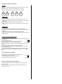
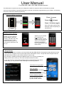
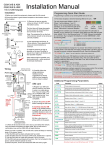
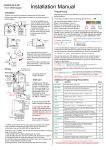
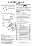
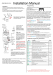
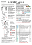
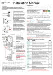
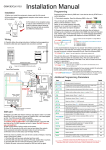
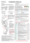
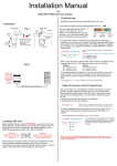
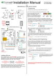
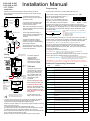
GSM-3AB & ABP
GSM-3HB & HBP
V3.5 PROX
Installation
Installation Manual
Programming
1) Before you install this equipment, please read this full manual.
Programming is carried out by sending SMS texts to the unit.
2) Ensure that there is good network reception at the location where it
will be installed.
1) First check reception. Send the following SMS to the unit... *20#
3) Remove the top two security
screws as shown. Do NOT remove
the bottom screws.
Call Button
The front door will hinge downwards
to allow access for mounting holes
and connection terminals.
Optional prox
module
ARCHITECTURAL
MODEL
HOODED
MODEL
Note: The protective film on the front
of the intercom should not be removed
until fully installed.
4) Use appropriate wall fixings. 810mm anchors, 75mm deep with M5
screw are recommended as a
minimum.
Hinge front door
Side View
5) Install the antenna as high as
possible on the top of the pillar to
ensure line of sight in all directions for
best possible reception.
Speech
Unit
200mm
min
4-5 feet
minimum
Keep antenna high as possible, and
above electronics + audio equipment
to eliminate interference
Entrance
Pillar
Wiring
Antenna connector.
Finger tighten only!
Power LED
GSM LED
GSM
modem
Searching
CPU LED
close
open
VCC
AC
AC
Busy
DETECT
GND
PB
GND
Standby
SIM card
holder
N/O
COM
N/C
-
12v dc
Output
+
Exit button
Status LED
Green when in
Add tag mode.
Green when relay
active.
RED when in SET
mode, & delete
tag mode.
Double flash
when error.
Optional
input limit
switch
from gate
5sec
1sec
set
run
Proximity
reader
- +
12v dc
Output
Note: Prox output must also be
connected to lock or gate system as
well as the GSM module output.
6) Carefully follow the
wiring instructions.
Additional wiring
suggestions for electric
strike lock and magnetic
lock are shown overleaf.
SIM card
7) Register your SIM card
with the network, and check
it works in a mobile phone
first. If you are using a Prepay or Pay&Go SIM, it will
need topped up first. Your
SIM should be GSM
compatible.
8) Ensure the power is OFF
before inserting the SIM card.
9) Carefully slide the SIM
holder in the OPEN direction,
insert the SIM, and slide in the
CLOSED direction to lock it in
place. Do NOT Force or use a
screwdriver!
10) After a final check of
wiring, switch on the power.
11) Allow 20-30 seconds for the unit to boot up and detect the network.
Once successful connection has been made, the unit will sound a
confirmation tone and the GSM LED will begin flashing.
If there is a fault or problem, the unit will emit a series of bleeps or warning
tones. If this occurs, check...
1) That the SIM card has been activated and has credit.
2) That the SIM card does not require a PIN code, disable this in a phone.
3) That the SIM card can make and received a call on a phone.
4) If the SIM card was purchased with a phone, that it is not locked to that
phone. Call the network operator to check.
5) Switch off power, remove and reseat the SIM card and try again.
1-12
Poor
13-20
Medium
21-31
Good
2) Program the numbers you wish the unit to dial when the call button is
pressed, up to a maximum of 3 numbers. Each SMS must start with the pass
code, default 1234, in the following format *12*1234#, followed immediately
by a command. E.g to program the telephone number 0987654321, enter
the following SMS..
Up to 3 numbers can be sent together in a single SMS as
follows..
*12*1234#110987654321#
*12*1234#11tel.number1#12tel.number2#13tel.number3#
11 = Telephone number 1
12 = Telephone number 2
13 = Telephone number 3
Pass code
Data
Function code
3) It is recommended to change the “no answer” time if there is more than 1
number stored. This stops the unit ringing a number after a set time, and can
be used to prevent voicemail answering the call. Send the following SMS..
*12*1234#52??# Where ?? can be 2 digits from 10-99 seconds, default is 20.
The unit can allow up to 100 telephone numbers to be stored, for users to
be able to ring the system for automatic entry. This uses caller ID like a
phone to determine the identity of the caller. First, the unit must know what
country it is operating in.
4) Program the country code as follows..
*12*1234#71??#
Side View
Network found
The unit should reply SIGNAL LEVEL = ?
Where ? will be between 1 and 31
Below 14 can cause problems with relay
operation, or no voice from the gate to the
house. Take action to improve reception.
Where ?? can be 1-3 digits. For uk, insert 44, for Ireland 353, for
USA insert 1. Do not use any leading zeros.
5) Enter the telephone numbers required to have access control. Do not enter
country code, just the complete number as you would dial it..
*12*1234#720987654321#
Up to 3 numbers can be sent together in the same SMS. Just
add 72 then the number, then # each time. The pass code only
needs to be put at the beginning of each new messge.
USA customers – For some networks, you may need to enter the numbers with the long distance 1
before area code, then the number. E.g. 1-702-555-1234. Try it with and without to see method works.
Additional Programming Parameters
Code
Description
Default
01????#
Change programming password.
1234
02????#
Change access control password (allows users not in caller ID list
to call intercom and use pass code to activate relay).
5678
03????#
Change monitoring mode password (dial to listen in mode)
1212
1n*#
Delete a button calling number, where n = number 1,2 or 3.
N/A
3?#
Speaker volume. Where ? = level 0 - 3
3
4?#
Microphone volume. Where ? = level 0 - 3
3
51?#
Relay time. Where ? = 1-9999 seconds.
1 sec
53??#
Max call time. Where ??? = 005-999 seconds (3 digit code)
60 sec
55??#
Max monitoring time (for listen in mode when calling the intercom)
00-60 mins. 00 = no limit.
10 min
57??#
Unit can call or SMS service number by set duration to prevent
SIM card deactivation if seldom used. 00-60 days. 00 = no inform.
00
58?#
Choose between scheduled call to service number or send SMS to
service number. ?=1 for SMS, 2 for call.
1
77number#
Store service number to receive scheduled SMS or call from
intercom.
N/A
77*#
Delete service number.
N/A
65?#
Dial in mode for withheld numbers or non stored numbers. 1 =
answer the call & wait for pass code. 2 = answer the call &
automatically activate 2 way speech.
73??#
Delete phone number for caller ID access.
N/A
73*#
Delete all phone numbers for caller ID access.
N/A
999#
Restore defaults
N/A
*21#
Check stored numbers. Note: no pass code needed for this
command. O = dial out number. I = Dial in number.
N/A
Remember to begin each new SMS with pass code *12*1234#
1
Proximity Module Features
Overview
The prox unit is a simple standalone device which can store up to 1000
tags.
The unit normally comes with 2 master tags and 3 user tags.
One of the master tags is an add tag, and one is a delete tag.
Add
Tag
Delete
Tag
User
Tag 1
User
Tag 2
User
Tag 3
Adding a Tag
To add a new tag…
1) Swipe the Add tag on the reader. The green LED should come on.
2) Swipe each new tag on the reader. The unit should give a single bleep
for each tag.
Swipe the Add tag again. The green LED should go off.
3) Wait 5 seconds, and swipe the new tags again to check they activate
the relay.
Deleting a Tag
To delete a tag…
1) Swipe the Delete tag on the reader. The LED should be RED.
2) Swipe the tags to be deleted on the reader. A bleep should be heard for
each Tag.
3) Swipe the Delete tag again. The RED LED should go off.
3) Wait 5 seconds, and swipe the deleted tags again to ensure they do not
operate the relay.
Setting up a new Add and Delete Tag
To create a new add and delete tag from the beginning the entire memory
will be deleted...
SET
1) Power off the prox unit.
2) Move the jumper on the prox PCB from RUN to SET.
RUN
3) Switch on the power. The RED LED should be on.
4) Swipe the tag which you wish to be the new Add tag (the unit should
bleep).
5) Swipe the tag which you wish to be the new Delete tag.
The unit should give a long bleep to indicate programming is complete.
6) Power off the prox unit.
7) Move the jumper back to the RUN position and switch on power again.
8) You may now swipe the ADD tag followed by tags you wish to add to
the unit.
Prox Relay time settings
The relay on the Prox unit is a volt free momentary relay.
Power capacity – up to 2A at 24v ac.
The relay time can be set for either 1 second or 5
seconds with the jumper link as shown,,,
5 sec
1 sec
Proximity Module Specifications
-125KHz, compatible with 4001 / 4100, EM / TEMIC / TK and other low
frequency cards.
-1 second & 5 second selectable output relay, N/C and N/O volt free.
-Scan range of 50mm.
User Manual
For GSM-3AB / ABK / HB / HBK Wireless Intercom
This GSM intercom system will call up to 3 telephone numbers in sequence when the call button is pressed.
There are several modes of operation depending on how the unit has been programmed by your installer. The following
instructions will assume default programming.
Intercom calling your phone
Press * to open
OR
1
4
7
*
2
5
8
0
3
6
9
#
END
Call button
pressed
Answer call.
Press # to hold open
and
Press 1 to release again
(Only some gate systems allow
hold open control, depending on
manufacturer)
Access Control Options
Option 1) If your number is
saved inside the intercom
memory, just dial it and it will
activate the door or gate
without answering your call.
The intercom will end the call
for you.
Dialling…
MY GATE
END
Option 2) If your number
is not saved in the
intercom memory, it will
answer the call. Enter the
code on your telephone
keypad to activate the
door or gate (default code
5678 shown).
*33*5678#
1
4
7
*
2
5
8
0
3
6
9
#
END
Using the App
If you are using iphone or Android, you can purchase the app (GSM-GATE). The app allows easy advanced control
of the intercom and gates or door by the simple press of the buttons shown. The app will need configured with the
SIM card phone number of your intercom before it can be used.
Once the app is installed, pressing the MENU button on your phone will display the
setting screen below, where you can enter the SIM card phone number.
If your gate system is set for timed operation where it automatically closes after a
preset delay, you may be able to take advantage of the latching features.
Press button to trigger gates
(speed dials your intercom)
Hold open gates
(sends latch SMS command)
Release / un-hold gates
(sends unlatch SMS command)
Press for additional features
1) Check gate open or closed
2) Check reception level
3) Check stored numbers
Sending SMS Commands
All of the features shown on the Android app are also available for non Android users, or non smart phone
users. You can simply send the same SMS commands manually to the intercom as detailed below...
*33*5678#
Momentary trigger output relay (default user pass code 5678)
*34*5678#
Latch output relay (default user pass code 5678)
*35*5678#
Un-latch output relay (default user pass code 5678)
*20#
Check reception level of intercom.
*21#
Check stored numbers. Unit will reply with list of stored numbers. I = dial in number. O = dial out number.
*22#
Check gate / door status. Unit will reply Relay = On/Off, Detect = On/Off
SIM cards & Credit
Please note that if you are using a Pay&Go or Pre-pay SIM card, which requires topped up occasionally, most network
providers provide a feature called Auto Top Up. This allows you to register the SIM card on their web site, and create a
payment method. When the credit runs low, the network will automatically top up your SIM card, so that you don’t have to
worry about running out. Contact your network provider in your country for more information or register with them online.
Fault finding & FAQs
Q. The unit will not power up. No LEDs on.
A. Check power supply voltage at intercom is within 11.5V-12.5V DC. Cable length from PSU to intercom should be less than 3 meters.
Q. The unit powers up but there is a bleeping from the door station.
A. This means the unit is not able to detect the network for some reason.
-Check the SIM card is activated and has calling credit.
-Power off the unit, remove the SIM and check it in a mobile phone to verify it can make a call.
-Check the SIM does not ask for a PIN code when put in a phone. If it does, then disable the PIN code request.
-Check the SIM is a standard GSM SIM, not 3G or 4G only SIM. If you are unsure, contact your SIM card provider to verify. Frequency of operation should
be any one of the international quad band standards, 850 / 900 / 1800 / 1900 MHz.
-Check the reception is good. Poor reception is not sufficient.
-Check the antenna has been mounted as high as possible, not near large metal objects, or wet green shrubs etc.
-Check the antenna connection. Visually inspect that the centre pin inside the antenna is intact, and has not been pushed back inside the fitting.
-Check voltage at the intercom is minimum 11.5V and that the cable from power supply to intercom is less than 3 meters.
Q. The unit calls the first number, but there is not enough time to answer before it diverts to the next number.
A. Increase the no answer time as per programming instructions.
Q. The unit calls the first number but voicemail comes on before it can ring the second number.
A. Decrease the no answer time as per programming instructions.
Q. The caller ID part does not work.
A. Be sure to program the caller ID part under 72 feature. If your number is a private or number withheld, then it will not work.
Even if you have already programmed a number to receive a call from the intercom, if you also want that number to have caller ID access, it must be
programmed under the 72 feature also.
Ensure the number is entered as you would normally dial it from another phone.
Do not put the country code in front of the number.
Enter the country code in which the unit is operating in separate under the 71 feature.
International callers ringing the intercom may not work.
Q. There is no audio from the gate, but the person at the gate can hear ok.
A. This can be due to low reception.
-Check reception level by *20#.
-Change SIM card if necessary to another network which may have better coverage.
-Purchase a high gain antenna.
This may also be caused by either a defective microphone. If reception is optimum and the problem persists, contact your supplier or dealer.
Q. The audio quality that can be heard on the remote telephone is poor or humming (buzzing).
A. A small amount of GSM buzz can be considered normal on GSM intercoms, but not so much that causes inability to hear the person speaking. This can
be caused by the GSM antenna being mounted too close to the speech panel or not mounted high enough.
-Try earthling the speech panel chassis to 0V of the power supply.
-This is also a symptom of poor reception. Try above steps on checking and improving reception.
Q. The * or # key does not work when the intercom calls a phone.
A. Check if you can hear the relay clicking at the gate when the * or # key is pressed during a call. If it can be heard, then the system is working, check
wiring between the relay and the lock or gate panel. If the relays do not make a clicking sound, then check this feature on a different mobile cell phone or
landline. If it works on a different phone, check the settings on the phone in question under DTMF tones.
Failure of DTMF tones to operate correctly is also a symptom of low reception. Check steps above on improving reception. Try pressing the buttons longer
when attempting to activate the gates or door.