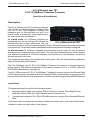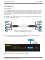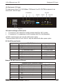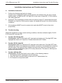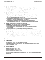
1
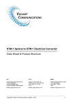
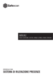
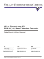
VALIANT COMMUNICATIONS LIMITED
VCL-4 Ethernet over 1E1
E1/4*10/(100) Base-T Interface Converter
Data Sheet & User Manual
U.K.
U.S.A.
INDIA
Valiant Communications (UK) Ltd
1, Acton Hill Mews,
310-328 Uxbridge Road,
London W3 9QN, United Kingdom
Valcomm Technologies Inc.
4000 Ponce de Leon, Suite 470
Coral Gables, FL 33146
U.S.A.
Valiant Communications Limited
71/1, Shivaji Marg,
New Delhi - 110015,
India
Valiant Communications Limited - 2006-10
1
Notice
Warranty
This Valiant product is warranted against defects in material and workmanship for a period of one
year from the date of shipment. During the warranty period, Valiant will, at its descretion, either
repair or replace products which prove to be defective. For warranty service or repair, this product
must be returned to a service facility designated by Valiant. The buyer shall prepay shipping
charges to Valiant and the company shall pay shipping charges to return the product to the buyer.
However, the buyer shall pay all shipping charges, duties and taxes for products returned to
Valiant from another country.
Limitation of Warranty
The foregoing warranty shall not apply to defects resulting from improper or inadequate
maintenance by the buyer, buyer-supplied firmware or interfacing, unauthorized modification or
misuse, operation outside of the environmental specifications for the product or improper site
preparation or maintenance.
Exclusive Remedies
The remedies provided herein are the buyer’s sole and exclusive remedies. Valiant shall not be
liable for any direct, indirect, special, incidental or consequential damages, whether based on
contract or any legal theory.
Notice
This manual contains information that is proprietary to Valiant Communications Limited. No part of
this publication may be reproduced in any form whatsoever without prior written approval by
Valiant Communications Limited.
Safety Warnings
!
The exclamation point within a triangle is intended to warn the operator or service
personnel of operation and maintenance factors relating to the product and its
operating environment which could pose a safety hazard.
Always observe standard safety precautions during installation, operation and maintenance of
this product. Only a qualified and authorized service personnel should carry out adjustment,
maintenance or repairs to this instrument. No adjustment, maintenance or repairs should be
performed by either the operator or the user.
UALITY ASSURANCE PROGRAM
Valiant’s products are designed and manufactured under a strict Quality
Assurance Program based on the ISO 9001:2008 philosophy and principles.
Valiant pays very special attention to its vendor development program which
ensures an “end-product” of the highest quality at the most cost effective prices.
Valiant Communications Limited - 2006-10
2
VCL-4 Ethernet over 1E1
Index
INDEX
Particulars
S. No.
P. No.
1.
General Description
4
2.
Typical Application
5
3.
Technical Features
7
4.
Installation, Open up and Commissioning
8
i
Qualifying the Networ
8
ii
Grounding
8
iii
Installation
8
Function Description
9
i
Front Panel
9
ii
Back Panel
11
iii
Bottom Panel
13
5.
6.
Installation Instruction and Trouble-shooting
14
7.
General Parameters
15
i
Power Supply
15
ii
Service conditions
15
iii
Dimensions
16
8.
Support
16
CAUTION
ELECTROSTATIC
SENSITIVE
DEVICES
DO NOT OPEN OR HANDLE
EXCEPT AT A
STATIC-FREE WORKSTATION
Valiant Communications Limited - 2006-10
3
VCL-4 Ethernet over 1E1
Descriptions and Applications
VCL-4 Ethernet over 1E1
E1/4*10(100)Base-T Interface Converter
(Data Sheet & User Manual)
Description
The VCL-4 Ethernet over E1 Converter provides the
user a facility to transport Ethernet (multiple LANs)
over an E1 link. The equipment converts and
transports upto 4 x Ethernet links over an E1 in a
shared* mode, or a discrete** mode, depending on
the user's preference and selection.
*In shared mode: All 4 Ethernet channels are
transported over the same shared E1 link and are
VCL-4 Ethernet over 1E1
allowed full access to each other's path. The user
may select this mode if the user desires that all of the 4 x Ethernet links that are being transported
over the same E1 to optimally share its bandwidth resources and where discretion is essential.
*In discrete mode: All 4 Ethernet channels are transported over the same E1 link, but without
allowing intrusion or access to each other's path. The user may select the discrete* mode when the
user desires to transport all 4 Ethernet channels over the same E1 line discretely, and without
allowing access to each other.
The equipment shall always be installed and used in pairs, with one terminal being installed at
either end (each side) of the network.
The VCL-4 Ethernet over E1, E1/4*10(100)Base-T Interface Converter is an ethernet extension
device utilizing TDM telecom infrastructure (the telecom network of E1s, or of PDH, SDH and
E1/E3/SDH microwave etc. carrying E1s).
The VCL-4 Ethernet over E1, E1/4*10(100)Base-T Interface Converter converts the Ethernet Data
into E1 frame format for transmission over the existing TDM (E1) links and then re-converts the E1s
back into Ethernet Data at the far-end terminal. It function is to primarily provide a BRIDGE between
Applications
This equipment may be used for the following purposes:
1.
2.
Bridging Ethernet LANs over existing TDM (E1) telecom network. Extending Ethernet
Networks utilizing TDM (E1) landline based telecom infrastructure.
Using telecom network of E1s / PDH / SDH Microwave etc. carrying E1s to transport Ethernet
Data.
In all these cases the equipment be always installed and used in pairs, with one terminal being
installed at either end (each side) of the network.
Valiant Communications Limited - 2006-10
4
VCL-4 Ethernet over 1E1
Typical Application
Typical Application
Shared link mode
In the "shared link mode", each LAN can view and talk to other LANs. Example: each LAN
can view and talk to all other LANs at same site or the corresponding remote side. This mode
may be selected for use if bandwidth optimization and usage is of prime importance and the
user is not averse to sharing the E1 link resources with the other LANs being transported on
the same E1 link.
For example all four Ethernet Ports at local site are in LAN Mode and will also communicate to
all four Ethernet Ports at far end site.
LAN 1
LAN 1
PC
PC
LAN 2
LAN 2
E1
E1
PC
LAN 3
E1Network
E1/4*10(100)Base-T
Interface Converter
PC
PC
E1/4*10(100)Base-T
Interface Converter
LAN 4
LAN 3
PC
LAN 4
Application Diagram of VCL-4 Ethernet over 1E1
Converter in V LAN Mode “shared link mode”
PC
PC
Note: In the "shared link mode", the VLAN switch must be OFF (The ethernet ports are not
isolated to each other on both sides of the E1 link).
VLAN
Switch OFF
VCL-4 Ethernet over 1E1
Valiant Communication
1
PWR
2
3
4
POWER
LINK
10/100M
1 2 3 4 5 6 7 8
Dup/Col
E1LOS E1SYL AIS
Note: Each DIP Switch is ON in downside and OFF in Upside.
Valiant Communications Limited - 2006-10
5
VCL-4 Ethernet over 1E1
Discrete Link Mode
Discrete link mode
In the "discrete link mode" each LAN is bridged to, and can only talk to its corresponding
LAN on the remote side. It can not talk to any other LAN either at same side or the remote
side. This mode may be selected for use if the users do not wish to share the E1 link resources
with the other LANs being transported on the same E1 link.
For example the Ethernet Port 1 (at local site) will communicate to Ethernet Port 1 at far end
site and so on for Port 2 etc.
LAN 1
LAN 1
PC
PC
LAN 2
LAN 2
E1
E1
PC
LAN 3
PC
PC
E1Network
E1/4*10(100)Base-T
Interface Converter
E1/4*10(100)Base-T
Interface Converter
LAN 4
LAN 3
PC
LAN 4
PC
PC
Application Diagram of VCL-4 Ethernet over 1E1
Converter in “discreet link mode”
Example: In the discrete link mode, the LAN 1 (Ethernet Port 1 of the equipment) only can talk to
the corresponding LAN 1 (Ethernet Port 1 of the equipment) at remote side and can not talk to any
other LAN, either on remote side or same side.
Note: In the discrete link mode, the VLAN switch must be ON (Ethernet Ports isolated) in Both
the units.
Valiant Communication
VCL-4 Ethernet over 1E1
1
2
3
CLK
RLOP
AUTO
SPD
D PX
SPDL1
SPDL2
VLAN
VLAN
Switch ON
4
PWR LINK
10/100M
Dup/Col
Dup/Col
1
2PWR
3
4
POWER
10/100M
LINK
E1SYL
AISover
E1LOS
VCL-4 Ethernet
1E1
1 2 3 4 5 6 7 8
POWER
POWER
1 2 3 4 5 6 7 8
E1LOS E1SYL AIS
Note: Each DIP Switch is ON in downside and OFF in Upside.
Valiant Communications Limited - 2006-10
6
VCL-4 Ethernet over 1E1
Technical Features
Technical Features
1.
The maximum transmission rate of 4 Ethernet data over E1 links is 2.048 Mbit/s
2.
Supporting 1600 long frames, accordance with Interior Switching Link (ISL) Protocol
3
Supporting local E1 port loop-back
4.
The Ethernet Port is self-adaptive to crossover or shoot-through (Straight/Parallel) cable
to avoid the trouble of re-wiring
5.
Supports up to four Ethernet Ports. Supports port mask
6.
Ethernet negotiation function. Supports 10M/100M and working modes of both
full-duplex and semi-duplex
7.
Transparently transmits ultra-long frames stipulated in IEEE 802.1Q, and supports
Ethernet switches with VLAN function
8.
Imbedded, dynamic Ethernet MAC address list (1024 addresses), and filter function for
local data frames
9.
Can support multiple LANs of different network addresses
10. Optional powers 220V AC and -48V DC. May be ordered with either power option.
E1 Port specifications
Number of E1 Ports
Line Rate E1
Framing
Electrical
Jitter
Impedance
Impedance
One
(2.048 Mbps ± 50 bps)
Un-Framed
As per ITU-T G.703
As per ITU-T G.823
120 Ohm (RJ-45)
75 Ohm (BNC)
Ethernet Port specifications
Number of Ports
Port Types
Standards Compliance
Data Rate
limited
Connectors
Valiant Communications Limited - 2006-10
Four
10/100BaseT (Auto-negotiating)
IEEE 802.3
10/100BaseT transmission rate
to 2.048Mbps (maximum)
RJ-45 (10/100 BaseT Electrical)
7
VCL-4 Ethernet over 1E1
Installation and Commissioning
Installation and Commissioning
1.
Qualifying the network
!
The time-slots should be configured according to the planning of E1 link. If the accessed
E1 link is being exclusively and only by this equipment (i.e. VCL-4 Ethernet over E1,
E1/4*10(100)Base-T Interface Converter), it should be configured as transparent
transmission to increase Ethernet service bandwidth
*** Note: Due care must be taken to ensure that the settings meet the user requirements
of “shared line" or "discrete line" service
!
The remote time-slots shall be configured in accordance with the local time-slots. The
configuration of the equipment on both sides should be the same
!
The length of the Ethernet cable shall not exceed 100m
2.
Grounding
!
When the equipment is used with the AC~220V power supply, the 3-core socket must be
grounded for protection
!
The other equipment (e.g. optical terminal) connected with this equipment must also be
grounded to earth for protection
3.
Installation
Step 1 Power up the Ethernet over E1 (IPoTDM) equipment.
Important: Please ensure that Ethernet over E1 (IPoTDM) equipment is powered-up prior to
connecting the ethernet and the E1 links.
Step 2 Connect E1 line after ensuring that transmission device, port converter and ethernet
switch have been grounded.
A Bit Error Rate (BER) test may be conducted on E1 link using a BERT tester to ensure that the E1
errors are within the permitted limits / threshold.
Step 3 Please configure the Ethernet Mode of the Ethernet over E1 (IPoTDM) equipment at both
sides as well as the Ethernet Ports of the devices that are connected to the Ethernet over E1
(IPoTDM) equipment. Connect the ethernet links.
The equipment is used to bridge Multiple LANs. Please ensure that the connecting LANs on both
sides of the link are operating in the same IP domain.
Step 4 Ping over the ethernet connection from one side to the other (near-end to the far-end)
to verify the link.
Important Note:
Please power-up the equipment prior to connecting the ethernet and the E1 links.
Valiant Communications Limited - 2006-10
8
VCL-4 Ethernet over 1E1
Front Panel
Description of the Front Panel
1.
Front Panel
Outline of the front panel of E1/4*10(100)Base-T Interface converter is as follows.
CLK
RLOP
AUTO
SPD
DPX
SPDL1
SPDL2
VLAN
E1SYL
Valiant Communication
VCL-4 Ethernet over 1E1
1
2
3
AIS
CL K
RLOP
AUTO
SPD
DPX
SPDL1
SPDL2
VLAN
E1LOS
4
PWR LINK
10/100M
Dup/Col
Dup/Col
1
2PWR
3
4
POWER
LINK
10/100M
E1SYL
AISover
E1LOS
VCL-4 Ethernet
1E1
1 2 3 4 5 6 7 8
POWER
POWER
1 2 3 4 5 6 7 8
E1LOS E1SYL AIS
Power LED: The GREEN LED indicator lights of power supply is lit under normal working
condition when the power supply is connected.
Valiant Communications Limited - 2006-10
9
VCL-4 Ethernet over 1E1
Definition of Indications
Definition of Indicators
Status of
Indicator light
Link LED GREEN
"ON" (Solid)
Link LED GREEN
"ON" (Flashing)
10/100M "Green"
10/100M "OFF”
Dup/Col "ON"
(Solid)
Dup/Col "OFF"
(Solid)
Dup/Col "OFF"
(Flashing)
Status of
Indicator light
E1 LOS RED "ON"
E1 LOS RED "OFF"
AIS YELLOW "ON"
AIS YELLOW "OFF"
Ethernet Port LEDs
Port 1
Port 2
Input Signal
Input Signal
Detected
Detected
Receiving/
Receiving/
Sending Data
Sending Data
Port under
Port under
100M service
100M service
mode
mode
Port under
Port under
10M service
10M service
mode
mode
Port under
Port under
full-duplex
full-duplex
mode
mode
Port under
Port under
semi-duplex
semi-duplex
mode
mode
Ethernet Port
Ethernet Port
has detected
has detected
any conflict
any conflict
error
error
Port 3
Input Signal
Detected
Receiving/
Sending Data
Port under
100M service
mode
Port under
10M service
mode
Port under
full-duplex
mode
Port under
semi-duplex
mode
Ethernet Port
has detected
any conflict
error
Port 4
Input Signal
Detected
Receiving/
Sending Data
Port under
100M service
mode
Port under
10M service
mode
Port under
full-duplex
mode
Port under
semi-duplex
mode
Ethernet Port
has detected
any conflict
error
E1 Circuit LED Alarm and status
E1 port is unconnected or bad connected
E1 port is connected properly
1's code alarm of E1 line
OK
Valiant Communications Limited - 2006-10
10
DIP Switch and Backpanel AC input
VCL-4 Ethernet over 1E1
DIP switch settings on front panel are as follows
Switch
1 (CLK)
Description
Default
ON
Internal clock: The system is running on its internal clock
ON
OFF
Line clock: The system is drawing clock from E1 line.
2 (RLOOP) ON
No loop-back on E1 interface.
ON
OFF
E1 Interface is loop-back.
3 (AUTO)
ON
Ethernet Port is running in self-adaptive mode.
ON
OFF
Ethernet Port rate is depend on SPD
4 (SPD)
ON
Ethernet Port rate is 100M if "AUTO" is off
ON
OFF
Ethernet Port rate is 10M if "AUTO" is off
5 (DPX)
ON
Ethernet Port is running in full-duplex mode
ON
OFF
Ethernet Port is running in semi-duplex mode
6 and 7
Speed Limit configuration of Ethernet Interface
(SPLD 1
SPLD 1 SPLD 2 Port Speed limit
ON
and SPLD 2) ON
ON
None port is speed limit
ON
OFF
1 and 2 port speed, limit 512 K; 3 and 4 port, no
Speed limit
OFF
ON
1 port speed limit, 1M; 2,3 and 4, no speed limit.
OFF
OFF
Speed limit, 512 K for all ports
8 (VLAN)
ON
Ethernet Port isolated (discrete link mode)
Off
OFF
Ethernet Port is not isolated (Share link mode)
Note: Each DIP Switch is ON in downside and OFF in Upside.
Power supply switch: To switch the power OFF/ON.
2.
(A) Back Panel: AC Input
The back panel of the E1/4*10(100)Base-T 4Ethernet Over E1 (IPoTDM) equipment is as
follows with AC Input
I/O/120W
ETHERNET
1
2
3
4
IN/75W
OUT/75W
G.703
ETHERNET
AC 220V
120/75W
120W
1 2 3 4
1
2
Y
Valiant Communications Limited - 2006-10
3
4
75W
IN/75W
I/O 120W OUT/75W
11
VCL-4 Ethernet over 1E1
Backpanel DC Input
(B) Backpanel: DC Input
The back panel of the E1/4*10(100)Base-T 4Ethernet Over E1 (IPoTDM) equipment is as
follows with -48V DC Input.
I/O/120W
ETHERNET
1
DC 48V
DC -48V
2
3
4
120/75W
IN/75W
OUT/75W
G.703
ETHERNET
120W
1 2 3 4
++ +
- +
Y
Y
Ground
1
2
3
4
75W
IN/75W
I/O 120W OUT/75W
Positive
Negative
DIP switch settings on Back panel
!
!
E1 socket for 120 W balanced: All DIP switches MUST be OFF (upside)
E1 socket for 75 W unbalanced: All DIP switches MUST be ON (downside)
AC220V: represents the unit uses AC~220V power supply.
*Optional powers 220V AC and -48V DC. May be ordered with either power option.
E1 RJ-45 Pinouts Details
PIN No.
1
2
3
4
5
6
7
8
120W RJ45 pin-out
Definition of function
NC
TX+ (transmitted data +)
TX- (transmitted data -)
NC
NC
RX+ (received data +)
RX- (received data -)
NC
Signal Direction
E1 Data Output
E1 Data Output
E1 Data Input
E1 Data Input
Ethernet RJ-45 Crossover Pinouts
PIN No.
1
2
3
4
5
6
7
8
Ethernet RJ-45 Crossover Pinouts
Definition of function
TX+ (transmitted data +)
TX- (transmitted data -)
RX+ (received data +)
NC
NC
RX- (received data -)
NC
NC
Valiant Communications Limited - 2006-10
Signal Direction
Data Output
Data Output
Data Input
Data Input
12
VCL-4 Ethernet over 1E1
3.
Bottom Panel
Bottom Panel:
The Bottom panel of the E1/4*10(100)Base-T 4Ethernet over E1 (IPoTDM) equipment is as
follows.
Time-slot configuration of E1 port: For E1 time-slot configuration, the DIP Switch settings on
the bottom panel are as follows:
Working Mode
Unframed
Framed (CCS/PCM-31)
Multi-Framed (CAS/PCM-30 )
Switch Setting
All switches are set to OFF
S0 set to OFF, and the occupied time slots to ON
All switches S0~S31 set to ON but S16 is set to OFF
The time-slot DIP switches located at the bottom of the equipment marked with TS0~TS31 bits
corresponding to 0~31 time-slots of E1 channel.
Note: It is recommended to set the TS0 DIP switch OFF.
Example 1: If you wish to use only first 5 time-slots then you need to set the S0 time-slots to OFF
and switch S1 to S5 to ON and time-slot S16 will be set to ON.
Example 2: If you wish to carry first 8 time-slots on 512Kbps, then you need to set the S0 time-slot
OFF and switch S1 to S8 to ON (i.e. since each time-slot consumes 64Kbps, so 8 time-slots will
consume 8 x 64Kbps = 512Kbps) and time-slot S16 will be set to ON.
Example 3: If you wish to carry 20 time-slots on 1.28Mbps (64Kbps x 20) then you need to set time
slot S0 OFF and S1 to S21 time-slots to ON. Please remember that the time-slot S16 will be used
as signaling time-slot.
Valiant Communications Limited - 2006-10
13
VCL-4 Ethernet over 1E1
Installation Instructions and Trouble-Shooting
Installation Instructions and Trouble-shooting
A
Installation Instruction
1.
Perform the following tests prior to usage:
Inspect every configuration switch on the panels to see whether they are set in normal
working state, i.e. PWR and E1 LOS light ON; in the case of framed E1, E1SYL shall be
ON, other lights OFF.
2.
Arrange E1 line impedance and time-slots as required, plug in E1 input/output lines and
Ethernet line, then turn ON the power supply, the equipment comes into normal working
conditions.
3.
One equipment MUST be set to master clock and other MUST be set to line clock
(loop-timed).
B
Trouble-shooting
When the equipment is under normal working conditions, the three indication lights, E1LOS
E1SYL and AIS, shall be OFF.
1.
Trouble: E1LOS light ON
Check point: make E1 loop-back at E1 input port and output port, if the light OFF, then
highlight the check on E1 input line. Please check with the E1 Cable.
2
Trouble: E1SYL light ON
Check point: Make E1 loop-back at E1 input port and output port, if the light OFF, then
highlight the check on the opposite-end interface converter to see whether set to framing
service mode. If the opposite side interface converter has been set to framing service
mode, check the transmission path of E1 for any disconnect. The alarm is valid if port is
working on framing mode.
3.
Trouble: AIS light ON
Check point: normally this fault is due to either of the following reasons:
1. The opposite-end E1 equipment cuts off receiving.
2. There are other devices working under test on E1 transmission line.
3. E1 Channel is in loop-back state.
Valiant Communications Limited - 2006-10
14
VCL-4 Ethernet over 1E1
General Parameters
4.
Trouble: LINK light OFF
Check point: This fault is basically due to the error in making network (crossover or
straight-through) cable. Please check if the equipment I require crossover cable or
straight-through cable you are connecting to. VCL-4 Ethernet over E1 is
self-adaptive to crossover or straight-through cable.
5.
Trouble: LINK light in normal state, but data PING fails
Check point:
1. Check whether the state of the equipment Ethernet is in accordance with that
of the opposite-end Ethernet; If not then, cancel the self-adaptive state of
Ethernet Interface and change compulsorily to configure speed and duplex
so as to be in accordance with the other end.
2. Check whether the equipment E1 port or E1 transmission channel is under
loop-back or other test conditions, if any, then cancel it.
3. Check whether the time slot configuration of the local equipment is in
accordance with the remote one. If not then, configure it to be in accordance.
6.
Trouble: Data succeed in PING, but with frame loss
Check point: This fault may be due to the following reasons:
1. Incompatible configuration of E1 port impedance.
2. Incomplete physical connection of E1 port, e.g. only one pole connected at
receiving end.
3. Wrong configuration of clock, change the clock to master clock.
7.
Trouble: The communication is normal prior to configure port mask, but blocked after port
mask configuration.
Check point: Ensure whether the remote equipment also configured port mask, whether
the port mask configuration at two ends is in accordance; after port mask configuration,
only Ethernet of same port number can perform communications. Check whether VLAN
switch set to OFF (shared link mode is ON) the equipment connected to Ethernet
interface, if any, Toggle the VLAN switch to ON (set the equipment for discrete link mode).
General
1.
Power Supply
AC Mains Input : 220V 20% (AC Mains input model).
*Optional powers 220V AC and -48V DC. May be ordered with either power option.
Power Consumption: 10W
2.
Service Conditions
Working temperature: -50C ~ +500C
0
0
Storage temperature: -20 C ~ +70 C
Relative humidity: 5 % ~ 95% (at 350C)
Do not subject the equipment to corrosive solvents, gas, dust or intense magnetic-field
interference.
Valiant Communications Limited - 2006-10
15
VCL-4 Ethernet over 1E1
Support
3.
Dimensions : 48cm x 4.3cm x 16cm
4.
Weight :
2 Kgs.
Note: Operation and maintenance of network equipment require professional knowledge and
experience. We recommend the equipment to be managed only by qualified technicians.
Should you require technical assistance please consult the provider, or contact our SUPPORT
DESK at [email protected], [email protected] :
Technical specifications are subject to changes without notice.
Windows is the registered Trademark of Microsoft Corporation, USA.
Revision 06 - January 30, 2010.
U.K.
U.S.A.
INDIA
Valiant Communications (UK) Ltd
1, Acton Hill Mews,
310-328 Uxbridge Road,
London W3 9QN, United Kingdom
Valcomm Technologies Inc.
4000 Ponce de Leon, Suite 470
Coral Gables, FL 33146
U.S.A.
Valiant Communications Limited
71/1, Shivaji Marg,
New Delhi - 110015,
India
Valiant Communications Limited - 2006-10
16