1
User's Manual
ServoCenter 3.1
USB
User's Manual
&
Programming Guide
Yost Engineering, Inc.
630 Second Street
Portsmouth, Ohio 45662
www.YostEngineering.com
©2002-2005 Yost Engineering, Inc.
Printed in USA
1
User's Manual
Table of Contents
1. Package Checklist........................................................................................................3
2. Function Overview...................................................................................................... 3
2.1 Introduction.................................................................................................................................. 3
2.2 Board Overview............................................................................................................................4
2.3 Features and Specifications......................................................................................................... 6
2.3.1 Features......................................................................................................................... 6
2.3.2 Specifications................................................................................................................ 6
Physical..............................................................................................................................6
Interface............................................................................................................................. 6
Electrical............................................................................................................................6
3 Installation.................................................................................................................... 7
3.1 General Installation Precautions................................................................................................ 7
3.2 Installing the ServoCenter 3.1 USB Drivers.............................................................................. 7
3.2.1 Before Installing Drivers............................................................................................... 7
3.2.2 Installing the Virtual Com Port Driver..........................................................................8
3.2.3 Installing the ServoCenter 3.1 Driver..........................................................................10
3.3 Connecting a Single ServoCenter 3.1 USB Board................................................................... 10
3.4 Connecting Multiple ServoCenter 3.1 Boards......................................................................... 11
3.4.1 “Daisy-Chaining” Multiple ServoCenter 3.1 USB Boards......................................... 11
3.4.2 Using Multiple ServoCenter 3.1 USB Boards on a USB Hub.................................... 13
3.5 Jumper Settings.......................................................................................................................... 13
3.5.1 Jumper JP1.................................................................................................................. 13
3.5.2 Jumper JP2.................................................................................................................. 14
3.5.3 Jumper JP3.................................................................................................................. 14
3.6 Board Identification Settings.....................................................................................................15
4 Programming the ServoCenter 3.1........................................................................... 16
4.1 Using the Virtual Com Port.......................................................................................................16
4.2 ServoCenter 3.1 Protocol........................................................................................................... 16
4.2.1 Protocol Overview...................................................................................................... 16
4.2.2 Packet Overview......................................................................................................... 17
4.2.3 Start of Packet Byte.....................................................................................................17
4.2.4 Command Set ............................................................................................................. 18
Command Summary........................................................................................................ 18
Command Details............................................................................................................ 19
4.2.5 The Checksum Value.................................................................................................. 24
4.3 Programming with Raw Serial I/O...........................................................................................25
4.3.1 QBASIC Example Program........................................................................................ 25
4.3.2 C++: Microsoft Visual C++ 6 Example Program....................................................... 26
4.3.3 C : Linux gcc Example Program................................................................................. 28
4.3.4 C : Borland Turbo C Sample Program........................................................................ 30
4.3.5 Visual Basic 6 Sample Program..................................................................................31
4.4 Programming With the ServoCenter 3.1 ActiveX Control.....................................................32
4.4.1 Operation with ServoCenter ActiveX Control............................................................ 32
4.4.2 Installing the ServoCenter ActiveX Control............................................................... 32
4.4.3 Using the ServoControl in Visual Basic 6.0............................................................... 33
4.4.4 ServoCenter 3.1 OCX Control Methods..................................................................... 34
4.4.5 Programming in Visual Basic 6.0 with the YEIServoControl.................................... 38
4.5 Programming With the ServoCenter 3.1 DLL........................................................................ 39
4.5.1 ServoCenter 3.1 DLL Functional Overview............................................................... 39
4.5.2 Installing the yeisrvo.dll Runtime Library.................................................................. 43
4.5.3 Programming with yeisrvo.dll in Visual Basic 6.0..................................................... 43
4.5.4 Programming with yeisrvo.dll in Visual C++ 6.0....................................................... 44
4.5.5 Programming with yeisrvo.dll in Visual C++ .NET................................................... 45
4.5.6 Programming with yeisrvo.dll in the Microsoft .NET Framework............................. 45
Visual Basic .NET........................................................................................................... 46
C#.................................................................................................................................... 46
5. Appendix.................................................................................................................... 47
5.1 Hexadecimal/Decimal/Binary Conversion Chart.................................................................... 47
5.2 Serial Cable Diagram.................................................................................................................47
5.3 ServoCenter 3.1 Circuit Schematic...........................................................................................48
2
User's Manual
1. Package Checklist
When you purchase this product you receive the following items:
•
ServoCenter 3.1 USB Controller Board
•
USB Device Cable (Type A to Type B)
•
AC Adaptor ( 9VDC@1500ma, Positive Center)
•
ServoCenter 3.1 USB User’s Manual & Programming Guide
•
ServoCenter 3.1 Software/Examples CD
Attention: The ServoCenter 3.1 USB Controller Board contains static sensitive devices.
Avoid touching the circuitry on the board and always handle the board by the edges
only.
Caution: Fully read this instruction manual before operating the ServoCenter 3.1 USB.
Misuse of the ServoCenter 3.1 USB board could result in equipment damage or injury.
2. Function Overview
2.1 Introduction
The ServoCenter 3.1 USB is an embedded controller that allows any device with a USB
port or serial port to control standard hobby servo motors. The board provides both a
USB and a serial interface to allow for easy control of the seek position and seek speed
of each of up to sixteen connected servos independently and simultaneously. This
independent control scheme allows one servo to be moving to a position slowly, while
another is moving to a different position quickly, while yet another is moving to
another position at a medium speed.
The ServoCenter USB controller also offers features such as absolute & relative control
command sets, raw & scaled positional modes, a simple yet reliable command protocol,
and on-board settings storage.
The ability to independently control both position and speed, combined with the
controller's flexible and extensible feature set make ServoCenter 3.1 USB especially
useful for servo control applications such as robotics, animatronics, motion control,
automation, retail displays, and other areas where independent or coordinated fluid
servo motion is necessary or desirable.
Up to 16 motors can be connected to each ServoCenter 3.1 USB board and up to 16
ServoCenter 3.1 boards can be “daisy-chained” together, thus allowing for a total of
256 RC servos to be controlled independently and simultaneously from one RS-232
serial port.
The ServoCenter 3.1 USB controller can be programmed using a simple raw command
protocol or can be programmed using the included ActiveX control and DLL.
ServoCenter 3.1 USB can be programmed via either the USB or serial port, and USB
communication is made simple through the use of the virtual COM port feature of the
USB drivers. Example programs illustrating various programming methods are
discussed in this user's guide and are provided on the included CD, along with the USB
drivers for the ServoCenter 3.1 USB.
3
User's Manual
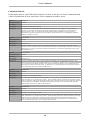
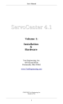
2.2 Board Overview
15. Jumper JP1
14. Power LED
1. Power Switch
13. Reset Button
12. Voltage Regulator
2. Power Supply Input
3. USB Connector Port
11. Board ID Switch
4. Serial IN Connector
10. Jumper JP2
5. Serial THRU connector
9. Jumper JP3
6. External Power Pads
8. Servo Connector 0-7
7. Servo Connector 8-15
1. Power Switch – The power switch is used to switch the controller board and the
attached servos off. The board will also not pass information from the serial IN port
to the serial THRU port when turned off.
2. Power Supply Input – Attach a 7-15VDC power source that can supply at least
1000ma supply current. The supply connector should be a 2.1mm x 5.5mm female
connector with a positive center.
3. USB Connector Port – The controller can receive control messages from this port.
This port should be connected to a standard USB port on the host computer system.
4. Serial IN Connector – The controller can receive its control messages from this
port. This port is wired as a DCE port and should be connected with a straightthrough serial cable to a PC serial port or the serial THRU port of another
ServoCenter controller. Serial port behavior is partially determined by jumper
settings.
5. Serial THRU Connector – Messages received on the serial IN port are sent to the
serial THRU port. This port is wired as a DTE port and should be connected to with
a straight-through serial cable to the serial IN port of another ServoCenter controller.
Serial port behavior is partially determined by jumper settings.
6. External Power Pads – If a jumper is installed on position 3 of JP3 then these pads
act as a source of external power which may be used to power additional servos or
circuitry at either 4.8Vdc or 6.0Vdc. If the jumper at position 3 of JP3 is not installed
then these pads may be used to connect an external servo power source such as a
battery or higher current supply.
7. Servo Connector 8-15 – Servos 8 through 15 are connected here. The servos should
always be connected so that the black ( ground ) wire of the servo is toward the
outside edge of the board.
4
User's Manual
8. Servo Connector 0-7 – Servos 0 through 7 are connected here. The servos should
always be connected so that the black ( ground ) wire of the servo is toward the
outside edge of the board.
9. Jumper JP3 – Position 1 of this jumper write protects the internal settings when
installed. Position 2 selects the voltage level provided to the servos as follows: 4.8
volts when installed, 6.0 volts when removed. Position 3 removes the on-board
regulator's voltage from the servo connector when removed. It is necessary to
remove this jumper when powering the servos from an external power source via the
external power pads.
10.Jumper JP2 – This jumper selects the serial data transfer rate as follows: both
positions removed = 9600bps, position 1 removed and 2 installed = 14400bps,
position 1 installed and position 2 removed = 19200bps, both positions installed =
38400bps. When USB connectivity is used the data rate setting for the “Virtual Com
Port” must match this jumper setting.
11.Board ID Switch – This switch determines the board ID of the ServoCenter
controller board. When multiple boards are “daisy-chained” they each require a
unique board ID setting to be controlled independently.
12.Voltage Regulator – This component supplies the power for all sixteen servos.
During normal operation the regulator will get HOT. To avoid injury be careful not
to touch the regulator during operation. To avoid fire do not allow combustible
materials to contact the regulator during operation. The regulator circuit is equipped
with both over-current and over-temperature shutdown circuitry.
13.Reset Button – This button allows the Servo Controller system to be reset without
cycling the power.
14.Power LED – When the power is on the power LED will be lit.
15.Jumper JP1 – This jumper controls the configuration of the serial communications.
When a jumper is installed in position 1, the module will receive command messages
from either the serial IN port or the USB port. This allows a board to be temporarily
disabled by removing this jumper. When a jumper is installed in position 2, the
module will be able to transmit messages to the PC. A jumper installed in position 3
allows this board to pass information to subsequently connected ServoCenter boards.
A jumper installed in position 4 allows subsequently connected ServoCenter boards
to pass information back to the serial IN and USB ports.
5
User's Manual
2.3 Features and Specifications
2.3.1 Features
•
Supports both USB and RS232 serial control.
•
USB connectivity allows complete servo control via the PC's USB port.
•
Standard RS-232 serial control at 9600,14400,19200, or 38400 bps.
•
Virtual COM Port feature makes USB communication just as easy as standard
RS-232 communication.
•
Control position and speed of all connected servos simultaneously.
•
Scaled motion commands allow maximum, minimum, and startup positionsetting, making complex motion programming easier.
•
Absolute and relative position commands allow for greater programming
flexibility.
•
Configuration information saved even when the power is off.
•
Control up to 16 RC servos per board. Daisy-chain up to 16 boards to control
up to 256 servos from one serial or USB port.
•
On-board voltage regulator supports both 4.8v and 6.0v servo supply voltages.
•
Over-current / over-temperature protection.
•
Includes USB device cable and 1500ma AC power supply.
•
Simple yet robust serial protocol makes programming simple.
•
Included ServoCenter ActiveX control and Win32 DLL makes creating
complex control applications fast and easy.
•
Included example programs get you started quickly.
•
Example programs included for VC6, VB6, QBASIC, Turbo C, VB.NET,
C#.NET, and GCC/LINUX.
•
Jumper settings allow for flexible configuration and control options.
2.3.2 Specifications
Physical
Size: 4.25"L x 3.5"W x 1.0"H (10.7cm L x 8.8cm W x 2.5cm H)
Weight: 2.7 oz
Interface
Input Interface: USB Type B port or 9-pin RS232 DCE interface.
Through Interface: 9-pin IBM style RS232 DTE interface.
Data Format (RS232 only): 8 data bits, no parity, 1 stop bit at 9600,
14400, 19200, or 38400 bps.
Servo Interface: 3-pin standard RC servo connector.
Electrical
Power Supply: 7.5VDC – 15VDC at no less than 1000ma.
Power Jack: 2.1mm x 5.5mm Male Jack, Center Positive.
Servo Power Output: Regulated 4.8VDC or 6.0VDC (selectable)
6
User's Manual
3 Installation
3.1 General Installation Precautions
The ServoCenter 3.1 board allows for several configuration options so that the user can
select the option that best suits the particular need required. In each configuration,
however, the installation procedure is basically the same. When installing or
configuring any ServoCenter 3.1 board, observe the following:
1. Some of the electronic components are sensitive and can be damaged by
electro-static discharge. Avoid touching the circuitry on the board itself and
handle the board only by the edges. Place the board in a static shielding bag
when storing the board for extended periods.
2. Use only the AC adaptor that was provided with the ServoCenter board. If an
alternate power supply is used ensure that it is of appropriate voltage,
amperage and polarity for the board.
3. When making changes in wiring, configuration, and jumper settings, be
careful not to touch the voltage regulator/heat-sink. These components get
hot and may cause injury if contacted.
4. The regulator and heat-sink of the ServoCenter controller get HOT during
periods of heavy utilization. Avoid placing the ServoCenter board in enclosed
spaces or in close proximity to combustible materials.
5. When connecting servo motors be careful to observe the polarity of the servo
connectors. The black wire should be connected toward the outside edge of
the board. Failure to observe the proper connector polarity could result in
damage to the ServoCenter board and/or the incorrectly connected servos.
6. If an external power source such as an alternate power supply or battery is
connected to the PWR connector, then ensure that the jumper on position 3 of
JP3 is removed.
3.2 Installing the ServoCenter 3.1 USB Drivers
Before the USB capabilities of the ServoCenter 3.1 USB may be used, two drivers must
be installed to the PC that will communicate with the controller board. The first driver
is the Virtual Com Port driver, which will allow your programs to access the
ServoCenter's USB port in the same way that RS232 serial ports are accessed (for more
information, see Section 4.1). The second driver is the ServoCenter 3.1 USB driver,
which is what allows the PC to communicate with the ServoCenter 3.1 USB.
3.2.1 Before Installing Drivers
Windows will automatically prompt you to install these drivers the first time you
connect the ServoCenter 3.1 USB to your PC. If you have the ServoCenter 3.1 CD,
insert it now. If not, you will need to download the ServoCenter 3.1 USB drivers from
http://www.YostEngineering.com/ServoCenter.
7
User's Manual
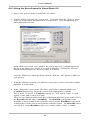
3.2.2 Installing the Virtual Com Port Driver
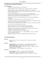
1. When the Found New Hardware Wizard starts, Windows may ask you if you
want to connect to Windows Update to search for drivers. If you see this
prompt, select “No, not this time.”
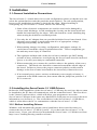
2. Next, the Wizard will tell you what device a driver is needed for and ask you if
you want to install the software automatically or install it from a specific
location. Choose “Install from a list or specific location (Advanced).”
8
User's Manual
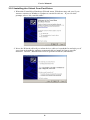
3. Next, you must tell the Wizard where to find the driver you need. Select the
box next to the “Include this location in the search:” option. If you have the
ServoCenter 3.1 CD, provide [CD]:\USB\Drivers as the location. If you
downloaded the drivers from the internet, you will need to specify the folder to
which you saved them.
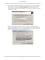
4. The Found New Hardware Wizard will now install the Virtual Com Port
Driver. Depending on your PC's security settings, you may see the following
message warning that the driver you're installing is not certified by Microsoft.
Click “Continue Anyway” to finish installing the driver.
9
User's Manual
5. Upon completion, the Wizard should inform you that the driver was
successfully installed.
3.2.3 Installing the ServoCenter 3.1 Driver
Follow the instructions outlined in Section 3.2.2 to install the ServoCenter 3.1 USB
Driver.
3.3 Connecting a Single ServoCenter 3.1 USB Board
Follow these steps to connect a single ServoCenter 3.1 USBboard.
1. Connect the USB port on the ServoCenter 3.1 USB controller board to a free
USB port on your PC using the provided USB cable.
-ORConnect the serial IN connector of the ServoCenter 3.1 USB to the serial port
of your PC (or other serial device) using a 9-Pin Serial Cable (DB9F to
DB9M).
2. Connect from 1 to 16 servos to the ServoCenter board’s servo ports.
3. Ensure that jumper settings are correct. ( See Section 3.5 )
4. Ensure that the board ID setting is correct. Generally board ID 0 is used in
single board applications, but any board ID can be used. ( See Section 3.6 )
10
User's Manual
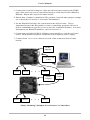
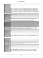
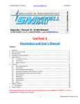
5. Connect the provided 9VDC@1500ma power supply to the ServoCenter
board.
9VDC
Adaptor
}
Serial or USB
Cable
Servo
Servo
. . .
Servo
Connecting a Single ServoCenter 3.1 Controller
3.4 Connecting Multiple ServoCenter 3.1 Boards
ServoCenter 3.1 has the capability to have up to 16 boards with unique servo
configurations connected together in a “daisy-chain” arrangement, or connected
independently from a USB “hub” device. This expandability allows for distinct and
precise control of up to 256 servo motors with one USB or serial port.
The ServoCenter boards can be identified from one another programmatically by
assigning each board an Identification Number. This can be achieved via the use of the
block of four switches located on the ServoCenter board. Please refer to Section 3.5
for more information on Identification Numbers.
3.4.1 “Daisy-Chaining” Multiple ServoCenter 3.1 USB Boards
Complete the following steps to “daisy-chain” multiple ServoCenter 3.1 USB Boards:
1. Connect the USB port on the ServoCenter 3.1 USB controller board to a free
USB port on your PC using the provided USB cable.
-OR2. Connect the serial IN connector of the ServoCenter 3.1 USB to the serial port
of your PC (or other serial device) using a 9-Pin Serial Cable (DB9F to
DB9M).
11
User's Manual
3. Connect the serial IN connector of the next ServoCenter board to the THRU
port of the previous ServoCenter Board using a 9-Pin Serial Cable (DB9F to
DB9M). Repeat this step for all other boards.
4. Ensure that a jumper is installed in JP1 position 3 and all other jumper settings
are as desired (see Section 3.4 for more information).
5. Set the Board ID switches for each board to the desired value. This is
important because this ID number is what a controlling program will use to
deliver commands to specific servos on specific controller modules. For more
information on Board ID numbers, refer to Section 3.6.
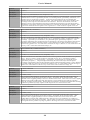
6. Connect the provided 9VDC@1500ma power supplies to each ServoCenter
board. Each module should be connected with a separate power supply.
7. Connect from 1 to 16 servo motors to each of the connected ServoCenter
boards.
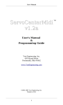
9VDC
Adaptor
}
Serial or USB
Cable
Servo
Servo
. . .
Servo
9VDC
Adaptor
Servo
Servo
. . .
Serial
Cable
Servo
“Daisy-Chaining” Multiple ServoCenter 3.1 Controllers
12
User's Manual
3.4.2 Using Multiple ServoCenter 3.1 USB Boards on a USB Hub
Complete the following steps to control multiple ServoCenter 3.1 USB Boards from a
USB Hub:
1. Connect a USB Hub to a USB port on your PC.
2. Connect a ServoCenter 3.1 USB Module to an open USB port on the hub
using a USB device cable. Repeat this step for all other boards.
3. Set the Board ID switches for each board to the desired value. This is
important because this ID number is what a controlling program will use to
deliver commands to specific servos on specific controller modules. For more
information on Board ID numbers, refer to Section 3.6.
4. Connect the provided 9VDC@1500ma power supplies to each ServoCenter
board. Each module should be connected with a separate power supply.
5. Connect from 1 to 16 servo motors to each of the connected ServoCenter
boards.
Note: While ServoCenter 3.1 will support up to 16 unique Identification Numbers at
one time, any number of ServoCenter boards may be assigned the same ID Number.
The result of this will be that all boards with the same ID number in a chain will
simultaneously move their respective servos to the same positions. This can be done to
obtain synchronized multiple servo movements or to divide high current servos across
multiple boards without consuming additional board IDs.
3.5 Jumper Settings
The ServoCenter 3.1 USB board has three sets of jumpers to allow various flexible
software and hardware control configurations. The functionality exhibited by these
jumper banks (Section 2.2 Items 9, 10, 14) when a jumper is installed is described in
each of the sections below.
3.5.1 Jumper JP1
Jumper JP1 controls the configuration of the serial communications mode. The
specific functionality of jumper JP1 is as follows:
Jumper JP1
Position Effect of Jumper When Installed
1
ServoCenter 3.1 USB board can receive messages from PC.
2
ServoCenter 3.1 USB board can send messages to PC.
3
Pass messages from PC to later boards in daisy-chain.
4
Pass messages from later boards in daisy-chain to PC.
13
User's Manual
When a jumper is installed in position 1, this ServoCenter board will be able to receive
messages from the PC. It is sometimes useful to remove the position 1 jumper to
temporarily disable a board without physically disconnecting it.
When a jumper is installed in position 2, this ServoCenter board will be able to transmit
messages to the PC.
When a jumper is installed in position 3, this ServoCenter board passes information to
subsequently connected ServoCenter boards.
When a jumper is installed in position 4, this ServoCenter board passes information
from subsequently connected ServoCenter boards to the PC or previous.
3.5.2 Jumper JP2
Jumper JP2 controls the configuration of the serial communications data rate, used if
you connect the ServoCenter 3.1 USB using a 9-pin Serial Cable. The specific
functionality of jumper JP2 is as follows:
Jumper JP2
Position 1
Position 2
Baud Rate Selected
Off
Off
9600bps
Off
On
14400bps
On
Off
19200bps
On
On
38400bps
3.5.3 Jumper JP3
Jumper JP3 controls the servo power options and the system settings write protection.
The specific functionality of jumper JP3 is as follows:
Jumper JP3
Position Effect of Jumper When Installed
1
System settings are write protected.
2
Servo voltage select. Regulated servo power is set to 4.8VDC when installed
and 6.0VDC when removed.
3
Internal regulated servo power is connected to the servo connectors.
When a jumper is installed in position 1, updates to the internal stored controller
settings are prohibited. This is useful for preventing accidental modification of stored
settings once they are entered. The controller will still allow changes to the settings,
but will not allow those changes to be committed to the persistent storage. Thus when
the power is cycled or the system is reset, then the stored settings will be restored.
When a jumper is installed in position 2, the on-board regulator provides 4.8VDC.
When the jumper is removed from this position then the regulator provides 6.0VDC.
14
User's Manual
When a jumper is installed in position 3, the on-board regulator supplies power to the
servo connectors. When the jumper is removed from this position the regulated power
is disconnected from the servo connectors. This jumper should be removed if an
external power source such as a battery is used to provide the servo power via the
“external power connection”. Removal of this jumper can also act as a quick method of
removing power from the servos without disconnecting their wires. To avoid damage,
never connect an external power source to the “external power connection” while this
jumper is installed.
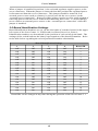
3.6 Board Identification Settings
Board Identification Numbers are set via the blue bank of switches located in the upper
left corner of the ServoCenter 3.1 USB board (see Board Overview, Item 6).
Identification numbers are determined by the position of each switch in the bank. The
settings of the switch indicate the binary representation of the board ID number. Refer
to the table below regarding the switch position/ID number relationship.
Board Identification Settings
1
2
3
4
Board ID
Off
Off
Off
Off
0
Off
Off
Off
On
1
Off
Off
On
Off
2
Off
Off
On
On
3
Off
On
Off
Off
4
Off
On
Off
On
5
Off
On
On
Off
6
Off
On
On
On
7
On
Off
Off
Off
8
On
Off
Off
On
9
On
Off
On
Off
10
On
Off
On
On
11
On
On
Off
Off
12
On
On
Off
On
13
On
On
On
Off
14
On
On
On
On
15
Board IDs can be changed at any time during the operation of the ServoCenter 3.1.
15
User's Manual
4 Programming the ServoCenter 3.1
4.1 Using the Virtual Com Port
The ServoCenter 3.1 USB controller board can be easily programmed via a RS232
serial port or a USB interface using the same codebase. This is made possible by
ServoCenter 3.1 USB's Virtual Com Port feature, which allows the USB port to be
opened, read from and written to just like a normal RS232 Com Port. No API or library
calls are necessary.
When users install the ServoCenter 3.1 USB drivers (see Section 3.2), the PC will
assign the device a unique Com number (e.g. Com1, Com2, etc.). Users can view what
Com number was assigned to the ServoCenter 3.1 USB board by using the Windows
Device Manager and selecting Ports.
The Com number assigned to the ServoCenter when the drivers are installed will only
be visible when the controller board is connected to the PC and powered on. Whenever
the controller is powered off, Windows will release the virtual Com port. When the
ServoCenter is reconnected to the PC, it will be assigned the same virtual Com number
that it was given when the drivers were installed.
4.2 ServoCenter 3.1 Protocol
4.2.1 Protocol Overview
The ServoCenter 3.1 controller receives messages from the controlling system in the
form of sequences of serial communication bytes called packets. Each byte is serial
encoded using 8N1 serial encoding ( 8 data bits, no parity, and 1 stop bit). The packet
size can range from three to six bytes in length, depending upon the nature of the
command being sent to the controller. Each packet consists of an initial “start of
packet” byte (which includes a board ID specifier), followed by a “command value”
specifier byte, followed by zero to three “command data” bytes, and terminated by a
packet “checksum value” byte.
The ServoCenter 3.1 controller buffers the incoming command stream and will only
take an action once the entire packet has been received and the checksum has been
verified as correct. Incomplete packets, packets with inappropriate board IDs, and
packets with incorrect checksums will be ignored. This allows the controlling system
to send command data at leisure without loss of function. The command buffer will,
however, be cleared whenever the ServoCenter controller is either reset or powered
off/on.
Most ServoCenter commands return no result data. Certain commands, however, are
designed to return status information about the current settings and positions of
connected servos. It is important to note that although many ServoCenter 3.1 boards
can be connected and controlled simultaneously by a single PC, only one of the
connected boards may be configured to send data back to the controlling system. The
transmit/receive functionality is controlled by the various jumper settings of jumper
block JP1.
16
User's Manual
4.2.2 Packet Overview
Each packet is from 3 to 6 bytes in length and is formatted as follows:
240(0xF0) + Board ID
Command ID
Command Data
Command Data
Command Data
First Byte – Start of Packet. Calculated by adding
240 to the desired board ID.
Second Byte – Command Value. Selected from
one of the possible control commands.
}
Checksum Value
Command Data/ Command Parameters.
Varies from zero to three bytes depending upon the
command specified in the second byte position. See
the table below for specific command data format
and specification.
Last Byte – Packet Checksum. See the checksum
description below for specific calculation information.
Typical ServoCenter 3.1 Command Packet
4.2.3 Start of Packet Byte
Each command packet starts with a specific type of byte called the “Start of Packet”
byte. The “Start of Packet” byte serves two purposes: to signify the start of a
command packet and to identify the board ID of the intended recipient. This byte's
value is calculated by adding 240 ( 0xf0 hex ) to the board ID of the board to which
you are sending the command message. Thus a byte value of 240(0xf0 hex) would be
used to send a message to the board with ID 0, 241(0xf1) for board ID 1, 242(0xf2) for
board ID 2, etc.
17
User's Manual
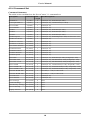
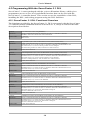
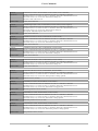
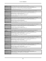
4.2.4 Command Set
Command Summary
The table below summarizes the ServoCenter 3.1 command set.
Description
Command Data
Data Descriptions
Length
QuickMove
0 (x00)
2
SvNum(0~15), SvPosition(0~200)
Scaled QuickMove
1 (0x01)
2
SvNum(0~15), %SvPosition(0~100%)
Servo Enable
2 (0x02)
1
SvNum(0~15)
Servo Disable
3 (0x03)
1
SvNum(0~15)
Set Min
4 (0x04)
2
SvNum(0~15), SvPosition(0~200)
Set Max
5 (0x05)
2
SvNum(0~15), SvPosition(0~200)
Set Start
6 (0x06)
2
SvNum(0~15), SvPosition(0~200)
Set Max Speed
7 (0x07)
2
SvNum(0~15), SvMaxSpeed(1~200) in centi-secs / 60°
Set Min to Current
8 (0x08)
1
SvNum(0~15)
Set Max to Current
9 (0x09)
1
SvNum(0~15)
Set Start To Current
10 (0x0a)
1
SvNum(0~15)
Get Current Position
11 (0x0b)
1
SvNum(0~15)
Get Min Position
12 (0x0c)
1
SvNum(0~15)
Get Max Position
13 (0x0d)
1
SvNum(0~15)
Get Start Position
14 (0x0e)
1
SvNum(0~15)
Get Max Speed
15 (0x0f)
1
SvNum(0~15)
Move Raw
16 (0x10)
3
SvNum(0~15), SvPosition(0~200), SvSpeed(1~100)
Move Raw CW
17 (0x11)
3
SvNum(0~15), ∆SvPosition(0~200), SvSpeed(1~100)
Move Raw CCW
18 (0x12)
3
SvNum(0~15), ∆SvPosition(0~200), SvSpeed(1~100)
Move Scaled
19 (0x13)
3
SvNum(0~15), %SvPosition(0~100), SvSpeed(1~100)
Move Scaled CW
20 (0x14)
3
SvNum(0~15), ∆%SvPosition(0~100), SvSpeed(1~100)
Move Scaled CCW
21 (0x15)
3
SvNum(0~15), ∆%SvPosition(0~100), SvSpeed(1~100)
Set Pulse Width Min
22 (0x16)
1
PwValue(1 – 239) in 10us units.
Set Pulse Width Max
23 (0x17)
1
PwValue(1 – 239) in 10us units.
Servo Reverse
24 (0x18)
1
SvNum(0~15)
Servo Normal
25 (0x19)
1
SvNum(0~15)
Show Settings
235 (0xeb)
0
None.
Commit Settings
236 (0xec)
0
None.
Load Factory Settings 237 (0xed)
0
None.
Reset as Startup
238 (0xee)
0
None.
Display Version
239 (0xef)
0
None.
18
User's Manual
Command Details
In the tables below you'll find a description of each of the ServoCenter commands and
a brief explanation of how and where each command would be used.
Function:
QuickMove
Command Value:
0 (0x00)
Data Bytes:
2
Data Format:
SvNum(0~15), SvPosition(0~200)
Description:
The QuickMove command provides a method of instantly moving a single servo (specified by
SvNum) to a specified raw position (specified by SvPosition). This function is useful when it is
desired to move a servo to a position as fast as possible. With QuickMove no servo position
interpolation is performed and the control signal for that specified servo is immediately modified
when the command is issued.
Function:
Servo Enable
Command Value:
2 (0x02)
Data Bytes:
1
Data Format:
SvNum(0~15)
Description:
The Servo Enable command provides a method of enabling a servo(specified by SvNum). This
function is used to enabled a servo channel that has been previously disabled. With the control signal
enabled the servo will actively hold its position. Enabled servos will draw significantly more power
than disabled servos.
Function:
Servo Disable
Command Value:
3 (0x03)
Data Bytes:
1
Data Format:
SvNum(0~15)
Description:
The Servo Disable command provides a method of disabling a servo(specified by SvNum). This
function is used to remove the control signal for a servo channel. With the control signal disabled the
servo will not actively hold its position. This can be useful for disabling a servo without having to
physically disconnect it from the board. A disabled servo can generally be moved by hand and will
draw significantly less power than an enabled servo.
Function:
Set Minimum
Command Value:
4 (0x04)
Data Bytes:
2
Data Format:
SvNum(0~15), SvPosition(0~200)
Description:
The Set Minimum command sets the minimum raw servo position set-point(specified by SvPosition)
of the specified servo (specified by SvNum). This minimum position is used in all scaled movement
modes of operation. Setting the minimum position above the start position will cause the start position
to be set equal to the minimum. Setting the minimum position above the maximum will cause the
maximum position to be set equal to the minimum.
Function:
Set Maximum
Command Value:
5 (0x05)
Data Bytes:
2
Data Format:
SvNum(0~15), SvPosition(0~200)
Description:
The Set Maximum command sets the maximum raw servo position set-point(specified by SvPosition)
of the specified servo (specified by SvNum). This maximum position is used in all scaled movement
modes of operation. Setting the maximum position below the start position will cause the start
position to be set equal to the maximum. Setting the maximum position below the minimum will
cause the minimum position to be set equal to the maximum.
19
User's Manual
Function:
Set Maximum Speed
Command Value:
7 (0x07)
Data Bytes:
2
Data Format:
SvNum(0~15), SvMaxSpeed(1~200)
Description:
The Set Maximum Speed command sets the maximum speed ( as specified by SvMaxSpeed and
measured in centi-seconds per 60° of travel) that is allowed for a particular servo channel (specified
by SvNum). This maximum speed is used to calculate all speed related seek commands. Different
servos have different rated travel speeds depending upon the manufacturer, model, and power supply
voltage. These speeds are generally rated in seconds per 60° of travel so the programmer will have
to convert the rated speed ( in seconds) to centi-seconds by multiplying by 100. The ServoCenter 3.1
controller allows the maximum allowable travel speed to be set independently for each of the 16 servo
channels.
Function:
Set Minimum to Current
Command Value:
8 (0x08)
Data Bytes:
1
Data Format:
SvNum(0~15)
Description:
The Set Minimum to Current command sets the minimum raw servo position set-point to the current
raw position of the servo of the specified servo (specified by SvNum). This minimum position is
used in all scaled movement modes of operation. Setting the minimum position above the start
position will cause the start position to be set equal to the minimum. Setting the minimum position
above the maximum will cause the maximum position to be set equal to the minimum.
Function:
Set Maximum to Current
Command Value:
9 (0x09)
Data Bytes:
1
Data Format:
SvNum(0~15)
Description:
The Set Maximum to Current command sets the maximum raw servo position set-point to the current
raw position of the specified servo (specified by SvNum). This maximum position is used in all
scaled movement modes of operation. Setting the maximum position below the start position will
cause the start position to be set equal to the maximum. Setting the maximum position below the
minimum will cause the minimum position to be set equal to the maximum.
Function:
Set Start to Current
Command Value:
10 (0x0a)
Data Bytes:
1
Data Format:
SvNum(0~15)
Description:
The Set Start to Current command sets the startup raw servo position set-point to the current raw
position of the specified servo (specified by SvNum). The start position is the position that the servo
will assume when the system is powered-up or reset. The start position is capped and cannot be set
greater than the maximum or less than the minimum.
Function:
Get Current Position
Command Value:
11 (0x0b)
Data Bytes:
1
Data Format:
SvNum(0~15)
Description:
The Get Current Position command causes the ServoCenter board to transmit a one byte message
corresponding to the raw servo position of a particular servo (specified by SvNum). The ability of
the board to send these responses is partially dependent upon the jumper settings of jumper block JP1
( see section 3.4.1 of the user's manual for details ).
Function:
Get Min Position
Command Value:
12 (0x0c)
Data Bytes:
1
Data Format:
SvNum(0~15)
Description:
The Get Min Position command causes the ServoCenter board to transmit a one byte message
corresponding to the currently set minimum servo position of a particular servo (specified by
SvNum). The ability of the board to send these responses is partially dependent upon the jumper
settings of jumper block JP1 ( see section 3.4.1 of the user's manual for details ).
20
User's Manual
Function:
Get Max Position
Command Value:
13 (0x0d)
Data Bytes:
1
Data Format:
SvNum(0~15)
Description:
The Get Max Position command causes the ServoCenter board to transmit a one byte message
corresponding to the currently set maximum servo position of a particular servo (specified by
SvNum). The ability of the board to send these responses is partially dependent upon the jumper
settings of jumper block JP1 ( see section 3.4.1 of the user's manual for details ).
Function:
Get Start Position
Command Value:
14 (0x0e)
Data Bytes:
1
Data Format:
SvNum(0~15)
Description:
The Get Start Position command causes the ServoCenter board to transmit a one byte message
corresponding to the currently set starting servo position of a particular servo (specified by SvNum).
The ability of the board to send these responses is partially dependent upon the jumper settings of
jumper block JP1 ( see section 3.4.1 of the user's manual for details ).
Function:
Get Max Speed
Command Value:
15 (0x0f)
Data Bytes:
1
Data Format:
SvNum(0~15)
Description:
The Get Max Speed command causes the ServoCenter board to transmit a one byte message
corresponding to the currently set maximum speed setting of a particular servo channel (specified by
SvNum). The ability of the board to send these responses is partially dependent upon the jumper
settings of jumper block JP1 ( see section 3.4.1 of the user's manual for details ).
Function:
Move Raw
Command Value:
16 (0x10)
Data Bytes:
3
Data Format:
SvNum(0~15), SvPosition(0~200), SvSpeed(1~100)
Description:
The Move Raw command is used to move a servo's position at a specified speed. The move raw
command moves a servo ( specified by SvNum ) to a raw position ( specified by SvPosition ) at a
particular speed ( specified by SvSpeed ). Raw movement modes do not use the set minimum and
maximum points to determine the servo's position. The specified speed is calculated as a percentage
of the preset maximum servo speed for the specified servo channel. Thus, a speed of 50 is half as fast
as a speed of 100, a speed of 1 is 1/100th as fast as a speed of 100, etc.
Function:
Move Raw CW ( Clockwise )
Command Value:
17 (0x11)
Data Bytes:
3
Data Format:
SvNum(0~15), ΔSvPosition(0~200), SvSpeed(1~100)
Description:
The Move Raw CW command is used to move a servo's position clockwise by a certain amount at a
specified speed. The move raw clockwise command moves a servo ( specified by SvNum ) clockwise
by a certain number of units ( specified by ΔSvPosition ) at a particular speed ( specified by
SvSpeed ).
Function:
Move Raw CCW ( Counter-Clockwise )
Command Value:
18 (0x12)
Data Bytes:
3
Data Format:
SvNum(0~15), ΔSvPosition(0~200), SvSpeed(1~100)
Description:
The Move Raw CCW command is used to move a servo's position counter-clockwise by a certain
amount at a specified speed. The move raw counter-clockwise command moves a servo ( specified by
SvNum ) clockwise by a certain number of units ( specified by ΔSvPosition ) at a particular speed
( specified by SvSpeed ).
21
User's Manual
Function:
Move Scaled
Command Value:
19 (0x13)
Data Bytes:
3
Data Format:
SvNum(0~15), %SvPosition(0~100), SvSpeed(1~100)
Description:
The Move Scaled command is used to move a servo's position at a specified speed. The move scaled
command moves a servo ( specified by SvNum ) to a scaled position ( specified by SvPosition ) at a
particular speed ( specified by SvSpeed ). Scaled movement modes use the set minimum and
maximum points to determine the servo's position. The scaled position value can be thought of as a
percentage of the range from the minimum to the maximum. Thus 0 is the minimum, 100 is the
maximum, and 50 is the midpoint between the set minimum and maximum. The specified speed is
calculated as a percentage of the preset maximum servo speed for the specified servo channel. Thus,
a speed of 50 is half as fast as a speed of 100, a speed of 1 is 1/100th as fast as a speed of 100, etc.
Function:
Move Scaled CW ( Clockwise )
Command Value:
20 (0x14)
Data Bytes:
3
Data Format:
SvNum(0~15), Δ%SvPosition(0~100), SvSpeed(1~100)
Description:
The Move Scaled CW command is used to move a servo's position clockwise at a specified speed.
The move scaled clockwise command moves a servo ( specified by SvNum ) clockwise by a certain
percentage ( specified by Δ%SvPosition ) at a particular speed ( specified by SvSpeed ). The
percentage indicated by the %SvPosition byte is based upon a percentage of the distance between the
minimum position and the maximum position. Thus a distance of 10 units would move the servo
clockwise by a distance of 1/10th of the entire scaled travel range, a distance of 1 unit would move the
servo by 1/100th of the entire scaled travel range, etc.
Function:
Move Scaled CCW ( Counter-Clockwise )
Command Value:
21 (0x15)
Data Bytes:
3
Data Format:
SvNum(0~15), Δ%SvPosition(0~100), SvSpeed(1~100)
Description:
The Move Scaled CCW command is used to move a servo's position counter-clockwise at a specified
speed. The move scaled counter-clockwise command moves a servo ( specified by SvNum )
counter-clockwise by a certain percentage ( specified by Δ%SvPosition ) at a particular speed
( specified by SvSpeed ). The percentage indicated by the %SvPosition byte is based upon a
percentage of the distance between the minimum position and the maximum position. Thus a distance
of 10 units would move the servo clockwise by a distance of 1/10th of the entire scaled travel range, a
distance of 1 unit would move the servo by 1/100th of the entire scaled travel range, etc.
Function:
Set Pulse Width Min
Command Value:
22 (0x16)
Data Bytes:
1
Data Format:
PwValue (1-239)
Description:
The Set Pulse Width Minimum command lets the user specify the minimum value of the range of
control pulses that are produced by the ServoCenter 3.1 board for all raw position modes. This
minimum value is applied globally to all servo channels of the board. Since some servos have slightly
different control pulse width ranges this value may have to be tweaked to get a full servo motion
range out of all raw position modes. The PwValue is measured in 10 microsecond units thus allowing
the board to produce any range of pulses in the range from 10 to 2390 microseconds.
Function:
Set Pulse Width Max
Command Value:
23 (0x17)
Data Bytes:
1
Data Format:
PwValue (1-239)
Description:
The Set Pulse Width Maximum command lets the user specify the maximum value of the range of
control pulses that are produced by the ServoCenter 3.1 board for all raw position modes. This
maximum value is applied globally to all servo channels of the board. Since some servos have
slightly different control pulse width ranges this value may have to be tweaked to get a full servo
motion range out of all raw position modes. The PwValue is measured in 10 microsecond units thus
allowing the board to produce any range of pulses in the range from 10 to 2390 microseconds.
22
User's Manual
Function:
Servo Invert
Command Value:
24 (0x18)
Data Bytes:
1
Data Format:
SvNum(0~15)
Description:
The Servo Invert command causes the servo channel specified by the first data byte (SvNum) to have
its positions seek in an inverted manner. This means that a raw position value of zero is the servo's
extreme counter-clockwise rotational position and 200 is the extreme clockwise position. This
function can be useful for dealing with paired servos or with servos that are mounted in such a way
that an inverted positional system is more natural.
Function:
Servo Normal ( UnInvert )
Command Value:
25 (0x19)
Data Bytes:
1
Data Format:
SvNum(0~15)
Description:
The Servo Normal command causes the servo channel specified by the first data byte (SvNum) to
have its positions seek in the normal, non-inverted, manner. This means that a raw position value of
zero is the servo's extreme clockwise rotational position and 200 is the extreme counter-clockwise
position.
Function:
Show Settings
Command Value:
235 (0xeb)
Data Bytes:
0
Data Format:
None.
Description:
The Show Settings command causes the board to transmit a table of the current settings for all
channels of the ServoCenter 3.1 board. The format of the returned data is a human-readable table
composed of ASCII characters. This fuction is useful when troubleshooting a board's settings or
simply verifying current board settings. The ability of the board to transmit data is dependent upon
the jumper settings of jumper block JP1 ( see section of the user's manual 3.4.1 for details ).
Function:
Commit Settings
Command Value:
236 (0xec)
Data Bytes:
0
Data Format:
None.
Description:
The Commit Settings command causes the board to save the current settings into the EEPROM
storage. Once the board's settings are stored in the EEPROM settings of the ServoCenter 3.1 they will
be restored every time the board is either reset or powered up. This allows the configuration to be
saved thus avoiding a configuration process every time the board is reset. Note: the EEPROM storage
of the ServoCenter 3.1 board has a limited lifetime of rewritability (about 100,000 rewrites) so avoid
writing a programmatic loop that continuously commits the settings of the board. The current rewrite
count can be viewed by using the “Show Settings” command. A user can prevent board settings from
being written by using jumper JP3 position 1 (see user's manual section 3.4.3 for info )
Function:
Load Factory Settings
Command Value:
237 (0xed)
Data Bytes:
0
Data Format:
None.
Description:
The Load Factory Settings command causes all of the board's settings to revert to the state that they
were in when shipped as new. This command only loads the settings and doesn't commit the settings
to the EEPROM of the board. To restore the settings and save these settings, the user should perform
a “Commit Settings” command following the “Load Factory Settings” command.
Function:
Reset as Startup
Command Value:
238 (0xee)
Data Bytes:
0
Data Format:
None.
Description:
The Reset as Startup command causes the board to perform a software reset of the control software.
This command is functionally equivalent to resetting or cycling the power of the board. All
EEPROM settings are loaded and all servo channels are modified according to these stored settings.
23
User's Manual
Function:
Display Version
Command Value:
239 (0xef)
Data Bytes:
0
Data Format:
None.
Description:
The Display Version command simply displays the version of the firmware embedded within your
ServoCenter 3.1 board. This can be useful for allowing software to query the board's version to
ensure interoperability between this and other/future YEI products.
4.2.5 The Checksum Value
The checksum is computed as an arithmetic summation of all of the characters in the
packet ( except the checksum value itself) modulus 239 plus one. This gives a
resulting checksum in the range 1 to 239. The checksum will be ignored if a 0 byte
value is passed in the checksum position of the packet.
The purpose of the checksum is to minimize the chances of the ServoCenter 3.1 board
receiving and acting upon corrupted or erroneous control messages. In most instances
the checksum should be used to enhance the reliability and robustness of the control
system, but, as noted above, a zero value can be placed in the checksum byte position
to ignore the checksum calculation.
This placing a 0 value in the checksum position can free the sender from having to
worry about calculating the actual checksum. This is useful in situations where
simplicity of implementation is necessary and reliable communication is not a
requirement.
24
User's Manual
4.3 Programming with Raw Serial I/O
The following section provides simple example programs in a variety of programming
languages and environments. Each example program illustrates how to access the
serial port and directly communicate with the ServoCenter 3.1 controller board to
control a servo. Note that the programs are provided to illustrate simple raw serial
communication using the ServoCenter 3.1 protocol and do not demonstrate the full
feature set of the ServoCenter 3.1 controller. Refer to section 4.1 for a description of
the entire ServoCenter 3.1 protocol and feature set.
4.3.1 QBASIC Example Program
DECLARE SUB initCOMPort (port AS INTEGER,baud as INTEGER)
DECLARE SUB MoveServoRaw (BoardNum AS INTEGER, ServoNum AS INTEGER,_
Position AS INTEGER, Speed AS INTEGER)
'*************************************************************
'* This demo program illustrates how to move servo motors
*
'* using raw serial communication access to the
*
'* Yost Engineering, Inc. ServoCenter 3.1 controller board. *
'*
*
'*
(c) 2001-2004
Yost Engineering, Inc.
*
'*
www.YostEngineering.com
*
'*
*
'*************************************************************
DIM
DIM
DIM
DIM
svBoardnum
svServonum
svPosition
svSpeed AS
CLS
COLOR
PRINT
PRINT
PRINT
PRINT
PRINT
15, 1
"
"
"
"
"
AS INTEGER
AS INTEGER
AS INTEGER
INTEGER
"
ServoCenter 3.1 Demonstration Program
(c)2000-2004 Yost Engineering, Inc.
www.YostEngineering.com
"
"
"
"
COLOR 7, 0
PRINT ""
'initialize the serial port com1 to 9600
CALL initCOMPort(1,9600)
DO WHILE
INPUT
INPUT
INPUT
INPUT
COLOR
PRINT
1 = 1
"
Enter a board number (0-15): ", svBoardnum
"
Enter a servo number (0-15): ", svServonum
"
Enter a position value (0-200): ", svPosition
"
Enter a seek speed value (1-100): ", svSpeed
4, 0
"
Sending Servo Command now...
"
CALL MoveServoRaw(svBoardnum, svServonum, svPosition, _
svSpeed)
COLOR 2, 0
PRINT "
Done!": PRINT
COLOR 7, 0
LOOP
SUB initCOMPort (port AS INTEGER, baud as INTEGER)
settings$ = "COM"+LTRIM$(STR$(port))+":"+LTRIM$(STR$(baud))+_
",N,8,1,CD0,CS0,DS0"
OPEN settings$ FOR RANDOM AS #1
END SUB
25
User's Manual
SUB MoveServoRaw (BoardNum AS INTEGER, ServoNum AS INTEGER, _
Position AS INTEGER, Speed AS INTEGER)
PRINT #1, CHR$(&HF0 + BoardNum MOD 16); CHR$(16);
PRINT #1, CHR$(ServoNum MOD 16);
PRINT #1, CHR$(Position MOD 201); CHR$(Speed MOD 101);
PRINT #1, CHR$(0);
END SUB
4.3.2 C++: Microsoft Visual C++ 6 Example Program
/***********************************************************\
* This demo program illustrates how to move servo motors
*
* using raw serial communication access to the
*
* Yost Engineering, Inc. ServoCenter 3.1 controller board *
* using Visual C++ 6.0.
*
*
*
*
(c) 2001-2004
Yost Engineering, Inc.
*
*
www.YostEngineering.com
*
*
*
\***********************************************************/
#include <windows.h>
#include <stdio.h>
#define PORTNUM 1
#define BAUDRATE 9600
void moveservo(HANDLE *,int,int,int,int);
int InitPort(unsigned int, unsigned int, HANDLE *, DCB *);
int main(int argc, char *argv[])
{
DCB dcb;
HANDLE hCom;
int i=0, BoardNum, ServoNum, Position, Speed;
printf("
printf("
printf("
printf("
printf("
ServoCenter 3.1 Demonstration Program
(c)2000-2004 Yost Engineering, Inc.
www.YostEngineering.com
\n");
\n");
\n");
\n");
\n");
if((InitPort(PORTNUM,BAUDRATE,&hCom,&dcb))!=0)//open serial port
{
printf("\tCould not initialize Comm Port!\n");
return (1);
}
else
{
while(1)
{
printf("\n Enter Board Number (0-15):");
scanf("%d",&BoardNum);
printf("\n Enter Servo Number (0-15):");
scanf("%d",&ServoNum);
printf("\n Enter Position (0-200):");
scanf("%d",&Position);
printf("\n Enter Speed (1-100):");
scanf("%d",&Speed);
printf("\n\tSending Command to Servo...\n");
moveservo(&hCom,BoardNum,ServoNum,Position,Speed);
printf("\n\tDone!\n");
}
}
return (0);
}
void moveservo(HANDLE *hCom,int board,int servo,int position,int
speed)
{
unsigned char buffer[6];
//create empty command packet
26
User's Manual
unsigned long BytesWritted;
//records # of bytes sent
buffer[0]=board%16 + 0xf0;
//board id #
buffer[1]=16;
//move raw command
buffer[2]=servo%16; //servo #--used to identify which servo
buffer[3]=position%201;//position to which the servo will move
buffer[4]=speed%101;
//speed at which servo will move
buffer[5]='\0';
//NULL character added to disable checksum
WriteFile(*hCom,buffer,5,&BytesWritted,NULL); //send packet
}
int InitPort(unsigned int PortNum, unsigned int BaudRate, HANDLE *hCom,
DCB *dcb)
{
BOOL fSuccess;
char pcCommPort[4]={'\0'};
if(PortNum==1)
sprintf(pcCommPort,"COM1");
else if(PortNum==2)
sprintf(pcCommPort,"COM2");
else if(PortNum==3)
sprintf(pcCommPort,"COM3");
else if(PortNum==4)
sprintf(pcCommPort,"COM4");
else
printf("\tPort Number not recognized\n");
*hCom = CreateFile( pcCommPort,
GENERIC_READ | GENERIC_WRITE,
0,
// must be opened with exclusive-access
NULL, // no security attributes
OPEN_EXISTING, // must use OPEN_EXISTING
0,
// not overlapped I/O
NULL // hTemplate must be NULL for comm
);
if (*hCom == INVALID_HANDLE_VALUE)
{
// Handle the error.
printf("\tCreateFile failed with error%d.\n",
GetLastError());
return (2);
}
// Build on the current configuration, and skip setting the size
// of the input and output buffers with SetupComm.
fSuccess = GetCommState(*hCom, dcb);
if (!fSuccess)
{
// Handle the error.
printf ("\tGetCommState failed with error %d.\n",
GetLastError());
return (3);
}
// Fill in DCB: Baudrate,8 data bits,no parity, 1 stop bit.
switch(BaudRate)
{
case 9600: dcb->BaudRate = CBR_9600; break;
case 14400: dcb->BaudRate = CBR_14400; break;
case 19200: dcb->BaudRate = CBR_19200; break;
case 38400: dcb->BaudRate = CBR_38400; break;
default:
printf("\tBaud Rate not recognized\n");
printf("\tUsing default rate of 9600bps.\n");
dcb->BaudRate = CBR_9600; break;
}
27
User's Manual
dcb->ByteSize = 8;
dcb->Parity = NOPARITY;
dcb->StopBits = ONESTOPBIT;
// data size, xmit, and rcv
// no parity bit
// one stop bit
fSuccess = SetCommState(*hCom, dcb);
if (!fSuccess)
{
// Handle the error.
printf("\tSetCommState failed with error %d.\n",
GetLastError());
return (4);
}
printf ("\tSerial port successfully reconfigured.\n");
return (0);
}
4.3.3 C : Linux gcc Example Program
/***********************************************************\
* This demo program illustrates how to move servo motors
*
* using raw serial communication access to the
*
* Yost Engineering, Inc. ServoCenter 3.1 controller board. *
* in Linux. This code was compiled using gcc.
*
*
(c) 2001-2004
Yost Engineering, Inc.
*
*
www.YostEngineering.com
*
*
*
\***********************************************************/
#include
#include
#include
#include
#include
#include
<stdio.h>
<string.h>
<unistd.h>
<fcntl.h>
<errno.h>
<termios.h>
int open_port(int portnum)
{
int fd;
char portfile[100]={'\0'};
if(portnum==1)
sprintf(portfile,"/dev/ttyS0");
else if(portnum==2)
sprintf(portfile,"/dev/ttyS1");
else if(portnum==3)
sprintf(portfile,"/dev/ttyS2");
else if(portnum==4)
sprintf(portfile,"/dev/ttyS3");
else
{
printf("open_port: unrecognized port number\n");
return (-1);
}
if((fd=open(portfile, O_RDWR | O_NOCTTY | O_NDELAY))==-1)
perror("open_port: unable to open /dev/ttyS0 - ");
return (fd);
}
void init_port(int *fd, unsigned int baud)
{
struct termios options;
//note: the termios structure does not support a baud rate of 14400
tcgetattr(*fd,&options);
28
User's Manual
switch(baud)
{
case 9600:
cfsetispeed(&options,B9600);
cfsetospeed(&options,B9600);
break;
case 19200:
cfsetispeed(&options,B19200);
cfsetospeed(&options,B19200);
break;
case 38400:
cfsetispeed(&options,B38400);
cfsetospeed(&options,B38400);
break;
default: cfsetispeed(&options,B9600);
cfsetospeed(&options,B9600);
break;
}
options.c_cflag |= (CLOCAL | CREAD);
options.c_cflag &= ~PARENB;
options.c_cflag &= ~CSTOPB;
options.c_cflag &= ~CSIZE;
options.c_cflag |= CS8;
tcsetattr(*fd,TCSANOW,&options);
}
void moveservo(int *fd, int boardnum, int servonum, int position, int
speed)
{
char buffer[6];
int num;
buffer[0]=boardnum%16 + 0xf0;
buffer[1]=0x10;
buffer[2]=servonum%16;
buffer[3]=position%201;
buffer[4]=speed%101;
//create packet
buffer[5]='\0';
num=write(*fd,buffer,5);
//send packet
}
int main()
{
int fd,board,servo,position,speed,portnum;
printf("
\n");
printf("
ServoCenter 3.1 Demonstration Program
\n");
printf("
(c)2000-2004 Yost Engineering, Inc.
\n");
printf("
www.YostEngineering.com
\n");
printf("
\n");
printf("Enter Port Number (1-4)\n");
scanf("%d",&portnum);
if((fd=open_port(portnum))==-1)
//open serial port
return (1);
init_port(&fd,9600);
//set serial port to 9600,8,n,1
while(1)
{
printf("Enter Board Number (0-15)\n");
scanf("%d",&board);
printf("Enter Servo Number (0-15)\n");
scanf("%d",&servo);
printf("Enter Position (0-200)\n");
scanf("%d",&position);
printf("Enter Speed (1-100)\n");
scanf("%d",&speed);
printf(“Sending Command...”);
moveservo(&fd,board,servo,position,speed);
printf(“done!\n”);
}
return (0);
}
29
User's Manual
4.3.4 C : Borland Turbo C Sample Program
/***********************************************************\
* This demo program illustrates how to move servo motors
*
* using raw serial communication access to the
*
* Yost Engineering, Inc. ServoCenter 3.1 controller board. *
* This program was written and compiled in the Borland
*
* Turbo C environment.
*
*
*
*
(c) 2001-2004
Yost Engineering, Inc.
*
*
www.YostEngineering.com
*
*
*
\***********************************************************/
#include<stdio.h>
#include<dos.h>
#include<conio.h>
#define COM1 0x3f8
#define COM2 0x2f8
#define COM3 0x3e8
#define COM4 0x2e8
/* Set following line to desired port*/
#define COMPORT COM1
#define BAUDRATE 9600
void initcom(unsigned int);
void moveservo(int,int,int,int);
main()
{
int board,servo,pos,speed;
clrscr();
printf("
printf("
ServoCenter 3.1 Demonstration Program
printf("
(c)2000-2004 Yost Engineering, Inc.
printf("
www.YostEngineering.com
printf("
initcom(BAUDRATE);
while (1)
{
printf("Enter Board ID (0-15)\n");
scanf("%d",&board);
printf("Enter ServoID (0-15)\n");
scanf("%d",&servo);
printf("Enter Position (0-200)\n");
scanf("%d",&pos);
printf("Enter Speed (1-100)\n");
scanf("%d",&speed);
printf("Moving servo...\n");
moveservo(board,servo,pos,speed);
printf("Done!");
}
}
\n");
\n");
\n");
\n");
\n");
void moveservo(int BoardId,int ServoNum,int Position,int Speed)
{
outportb(COMPORT,0xf0 + BoardId % 16);
while((inportb(COMPORT+5)&0x20)==0){;}
outportb(COMPORT,0x10);
while((inportb(COMPORT+5)&0x20)==0){;}
outportb(COMPORT,ServoNum % 16);
while((inportb(COMPORT+5)&0x20)==0){;}
outportb(COMPORT,Position % 201);
while((inportb(COMPORT+5)&0x20)==0){;}
outportb(COMPORT,Speed % 101);
while((inportb(COMPORT+5)&0x20)==0){;}
outportb(COMPORT,0);
while((inportb(COMPORT+5)&0x20)==0){;}
}
30
User's Manual
void initcom( unsigned int BaudRate )
{
outportb(COMPORT+3,0x83); //DLAB high, set format 8N1
switch(BaudRate)
{
case 9600: outportb(COMPORT,0x0c);
// set rate LSB
outportb(COMPORT+1,0x00); // set rate MSB
break;
case 14400:outportb(COMPORT,0x08);
// set rate LSB
outportb(COMPORT+1,0x00); // set rate MSB
break;
case 19200:outportb(COMPORT,0x06);
// set rate LSB
outportb(COMPORT+1,0x00); // set rate MSB
break;
case 38400:outportb(COMPORT,0x03);
// set rate LSB
outportb(COMPORT+1,0x00); // set rate MSB
break;
default:
//use 9600 as default baud rate
outportb(COMPORT,0x0c);
// set rate LSB
outportb(COMPORT+1,0x00); // set rate MSB
break;
}
outportb(COMPORT+3,0x03); // DLAB now low
outportb(COMPORT+1,0x00); // Interrupts off
}
4.3.5 Visual Basic 6 Sample Program
For the purpose of this sample, a simple VB form consisting of four Text Boxes, a
Command Button, and the MSComm Control was used. Please refer to the project file
on the CDROM for further details.
This example makes use of two program events: the Form_Load event and the
cmdMove_Click event. The code attached to these events can be seen below.
'
'
'
'
'
'
'
This program communicates with the ServoCenter 3.1 board
by using the raw packet format in Visual Basic 6. The serial
port is accessed
in this example via the Microsoft Comm Control
(c) 2000-2004 Yost Engineering
www.YostEngineering.com
Private Sub cmdMove_Click()
txtBoardNum.Text = Trim$(txtBoardNum.Text)
txtServoNum.Text = Trim$(txtServoNum.Text)
txtPosition.Text = Trim$(txtPosition.Text)
txtSpeed.Text = Trim$(txtSpeed.Text)
MSComm1.Output = Chr$(&HF0 + Val(txtBoardNum.Text)) & Chr$(16)_
& Chr$(Val(txtServoNum.Text)) & Chr$(Val(txtPosition.Text)) _
Chr$(Val(txtSpeed.Text)) & Chr$(0)
' output the packet
End Sub
Private Sub Form_Load()
MSComm1.CommPort = 1
'use comm1
MSComm1.Settings = “9600,8,N,1”
'set up comm port.
MSComm1.PortOpen = True
'open the port
End Sub
31
&
User's Manual
4.4 Programming With the ServoCenter 3.1 ActiveX Control
To avoid the raw serial method of programming the ServoCenter 3.1 board, the
YEIServoCenter ActiveX Control can be used (in a Visual Basic 6.0 project). This
Control is designed to allow the programmer to concentrate on controlling the servos
without having to worry about the ServoCenter 3.1 communications protocol. Below is
an explanation of how to program the ServoCenter 3.1 using the YEIServoCenter
ActiveX Control.
4.4.1 Operation with ServoCenter ActiveX Control
The ServoCenter 3.1 CD contains a custom ActiveX Control. The ServoCenter Control
was designed to be extremely easy to install and program with.
4.4.2 Installing the ServoCenter ActiveX Control
1. Copy YEIServoControl.ocx from the CD to the ActiveX control directory. In
Windows 95/98/ME, ActiveX controls are stored in C:\WINDOWS\SYSTEM\.
In Windows 2000/XP, they are stored in C:\WINDOWS\SYSTEM32\.
2. Register YEIServoControl.ocx. To do this, click the Start button, and then select
Run. Into the Run dialog box, type “Regsvr32.exe” followed by a space and then
the path and filename of the ServoControl.
If the control is successfully registered, you will see a dialog box like this…
The Control is now installed and ready for use!
32
User's Manual
4.4.3 Using the ServoControl in Visual Basic 6.0
1. Open a new project in the Visual Basic 6.0 editor.
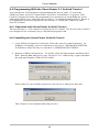
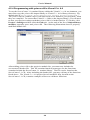
2. Add the YEIServoControl to your project. To do this, click the “Project” menu
at the top of the editor and then select “Components”. This should bring up a
menu that looks like this:
If the YEIServoControl was copied to the correct directory, it should appear in
the list in the dialog box. If not, it can still be added by clicking the “Browse”
button and browsing to the directory where it is stored.
Once the YEIServoControl has been selected, click the “OK” button to add it to
your project.
3. With the YEIServoControl now added to your project, select it from the toolbox
and draw it on the form.
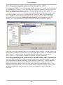
4. In the “Properties” pane of the VB editor, specify the communications port
(ComPort property) by which the control will communicate with the
ServoCenter 3.1 board. A ComPort property of 1 will signify Com1, a 2 will
signify Com2, and so on up to Com4.
There are two more properties that deal with communication to the board. One is
the BoardID and the other is BaudRate. The BoardID corresponds to the
BoardID switches found on the controller board, and the BaudRate is the speed
at which data will be sent to and from the controller board. The BoardID can be
set from 0 to 15 and BaudRate can be set to 9600,14400,19200, or 38400.
33
User's Manual
Make sure that the board has the correct jumper settings on JP2 and that your
board's ID switches are in the correct positions to ensure successful
communication.
5. There are several other entries in the “Properties” pane. One is the
ServoConfigFile property. This property can be used to specify a file which
will store servo min, max, and start information for up to 16 ServoCenter 3.1
boards. A related property is the AutoCreateConfigFile property. Setting this
property to True will cause a file to be created to store settings, even if a name is
not specified in the ServoConfigFile property.
The boolean property SynchronizeBoard determines where the values that are
displayed on the ServoConfig screen are pulled from. If SynchronizeBoard is
True, the values displayed on the ServoConfig screen are polled from the board
with the current BoardID. If SynchronizeBoard is False, the control will not
poll the current board, but will show the data for the current BoardID that is in
the file that was specified by ServoConfigFile.
This completes the process of preparing the project for ServoCenter 3.1 use. You
may now begin writing code to control the servos attached to your ServoCenter 3.1.
To ensure the proper functionality of the YEIServoControl, please note that the
InitBoard method must be invoked before attempting to access the ServoCenter 3.1
board. Once the InitBoard method has been executed, the servos attached to the
ServoCenter 3.1 board can be manipulated, and information about these servos can
be displayed, with the methods described in Section 4.3.4.
4.4.4 ServoCenter 3.1 OCX Control Methods
All of YEIServoControl's movement and set methods take integer arguments, and all of
the get methods return integers, unless otherwise specified. All methods below which
are followed by an asterisk (*) have a counterpart that will perform the same function,
but to all servos [0-15]. For example: the QuickMove method will move a single servo
to a specified position and the QuickMoveAll method will move all 16 servos to the
specified position. The methods below which are followed by 2 asterisks (**) also
have an All counterpart, which returns an array of integers [0-15]. Only the single servo
version of each method will be fully described.
Value ranges for arguments:
ServoNum – 0 to 15
ServoPosition, ChangeInServoPosition – 0 to 200
ScaledServoPosition, PercentOfSpeed – 0 to 100
ServoMaxSpeed, PulseWidth10usUnits – 1 to 239
QuickMove Method*
The QuickMove method moves the specified servo to the specified position. This method is of
the form:
YEIServoCtrl1.QuickMove(ServoNum, ServoPosition)
34
User's Manual
QuickScaledMove Method*
The QuickScaledMove method moves the specified servo to the specified scaled position. The
scaled position is really a percentage of the distance between the specified servo's min and max.
This method is of the form:
YEIServoCtrl1.QuickScaledMove(ServoNum, ScaledServoPosition)
ServoEnable Method*
The ServoEnable method will enable the specified servo. This method is of the form:
YEIServoCtrl1.ServoEnable(ServoNum)
ServoDisable Method*
The ServoDisable method will disable the specified servo. This method is of the form:
YEIServoCtrl1.ServoDisable(ServoNum)
SetMin Method*
The SetMin method sets the min position for the specified servo to a specified position. This
method is of the form:
YEIServoCtrl1.SetMin(ServoNum, ServoPosition)
SetMax Method*
The SetMax method sets the max position for the specified servo to the specified position. This
method is of the form:
YEIServoCtrl1.SetMax(ServoNum, ServoPosition)
SetStart Method*
The SetStart method sets the start position for the specified servo to the specified position. This
method is of the form:
YEIServoCtrl1.SetStart(ServoNum, ServoPosition)
SetMaxSpeed Method*
The SetMaxSpeed method sets the maximum speed rating for the specified servo. This rating
is normally in µs units. Multiplying ServoMaxSpeed by 10µs yields the maximum speed. This
method is of the form:
YEIServoCtrl1.SetMaxSpeed(ServoNum, ServoMaxSpeed)
SetMaxCurrent Method*
The SetMaxCurrent method takes the current raw position of the specified servo and sets its
max position equal to it. This method is of the form:
YEIServoCtrl1.SetMaxCurrent(ServoNum, ServoPosition)
SetMinCurrent Method*
The SetMinCurrent method takes the current raw position of the specified servo and sets its
min position equal to it. This method is of the form:
YEIServoCtrl1.SetMinCurrent(ServoNum)
SetStartCurrent Method*
The SetStartCurrent method takes the current raw position of the specified servo and sets its
start position equal to it. This method is of the following form:
YEIServoCtrl1. SetStartCurrent (ServoNum)
35
User's Manual
GetCurrentPos Method**
The GetCurrentPos method gets the current position of the specified servo and returns it. This
method is of the form:
YEIServoCtrl1.GetCurrentPos(ServoNum)
GetMin Method**
The GetMin method gets the min position of the specified servo and returns it. This method is
of the form:
YEIServoCtrl1.GetMin(ServoNum, ServoPosition)
GetMax Method**
The GetMax method gets the max position of the specified servo and returns it. This method is
of the form:
YEIServoCtrl1.GetMax(ServoNum, ServoPosition)
GetStart Method**
The GetStart method gets the start position of the specified servo and returns it. This method is
of the form:
YEIServoCtrl1.GetStart(ServoNum, ServoPosition)
GetMaxSpeed Method**
The GetMaxSpeed method gets the max speed of the specified servo and returns it. This
method is of the form:
YEIServoCtrl1.GetMaxSpeed(ServoNum, ServoPosition)
MoveRaw Method*
The MoveRaw method moves the specified servo to the specified position at the specified
percent of the max speed for that servo. This method is of the form:
YEIServoCtrl1.MoveRaw(ServoNum, ServoPosition, PercentOfSpeed)
MoveRawCW Method*
The MoveRawCW method moves the specified servo in the Clockwise direction in the amount
specified by ChangeInServoPosition at the specified percent of the max speed for that servo.
This method is of the form:
YEIServoCtrl1.MoveRawCW(ServoNum, ChangeInServoPosition,
PercentOfSpeed)
MoveRawCCW Method*
The MoveRawCCW method moves the specified servo in the Counter-Clockwise direction in
the amount specified by ChangeInServoPosition at the specified percent of the max speed for
that servo. This method is of the form:
YEIServoCtrl1.MoveRawCCW(ServoNum, ChangeInServoPosition,
PercentOfSpeed)
MoveScaled Method*
The MoveScaled method moves the specified servo to the specified scaled position at the
specified PercentOfSpeed. The scaled position is really a percentage of the distance between
the specified servo's min and max. This method is of the form:
YEIServoCtrl1.MoveScaled(ServoNum, ScaledServoPosition,
PercentOfSpeed)
36
User's Manual
MoveScaledCW Method*
The MoveScaledCW method moves the specified servo to the specified scaled position in a
Clockwise direction at the specified PercentOfSpeed. The scaled position is really a percentage
of the distance between the specified servo's min and max. This method is of the form:
YEIServoCtrl1.MoveScaledCW(ServoNum, ScaledServoPosition,
PercentOfSpeed)
MoveScaledCCW Method*
The MoveScaledCCW method moves the specified servo to the specified scaled position at the
specified PercentOfSpeed. The scaled position is really a percentage of the distance between
the specified servo's min and max.This method is of the form:
YEIServoCtrl1.MoveScaledCCW(ServoNum, ScaledServoPosition,
PercentOfSpeed)
SetPulseWidthMin Method
Servos require a pulse to move the servo to a specified location. The pulse width min is set to
(PulseWidth10usUnits * 10µs), so passing 1 sets the PulseWidthMin to 10 µs. This method is
of the form:
YEIServoCtrl1.SetPulseWidthMin(PulseWidth10usUnits)
SetPulseWidthMax Method
Servos require a pulse to move the servo to a specified location. The pulse width max is set to
(PulseWidth10usUnits * 10µs), so passing 100 sets the PulseWidthMax to 1000 µs. This
method is of the form:
YEIServoCtrl1.SetPulseWidthMax(PulseWidth10usUnits)
GetSettings Method
The GetSettings method returns a string containing information about the status of all of the
servos. This information can be corrupted if you're sending data at the same time that you are
trying to get data. This method is of the form:
YEIServoCtrl1.GetSettings()
CommitSettings Method
The CommitSettings method takes the current min values, max values, and other settings and
stores them in the EEPROM on the ServoCenter 3.1 board . These settings will then be loaded
the next time the board is restarted. This method is of the form:
YEIServoCtrl1.CommitSettings()
RestoreFactory Method
The RestoreFactory method restores the settings to the Factory Settings. This method is of the
form:
YEIServoCtrl1.RestoreFactory()
ResetAsStartup Method
The ResetAsStartup method does a software restart of the system. It takes the stored settings
and sets the current settings to them. This method is of the form:
YEIServoCtrl1.ResetAsStartup()
GetVersion Method
The GetVersion method returns a string that contains the copyright information and version of
the board. This method is of the form:
YEIServoCtrl1.GetVersion()
37
User's Manual
ShowServoConfig Method
The ShowServoConfig method displays the configuration dialog box for the board. This
method is of the form:
YEIServoCtrl1.ShowServoConfig()
InitBoard Method
The InitBoard method initializes the COM port and loads settings for the servos. This method
is of the form:
YEIServoCtrl1.InitBoard()
4.4.5 Programming in Visual Basic 6.0 with the YEIServoControl
The following code examples illustrate the use of the YEIServoControl in Visual Basic
6.0.
Here is an example of how to initialize your ServoCenter 3.1 Board:
Private Sub Form_Load()
YEIServoCtrl1.InitBoard
YEIServoCtrl1.BoardID = 0
End Sub
'initialize the control
' set board id to 0
Here is an example of how to move a servo by clicking on a button:
Private Sub cmdMoveServo_Click()
Call YEIServoCtrl1.QuickMove(0, 100)
'Move servo 0 to raw position 100
End Sub
Here is an example of how to show the servo configuration dialog box:
Private Sub cmdShowConfig_Click()
YEIServoCtrl1.ShowServoConfig
End Sub
'show config dialog
The DirectSerial.vbp project, located on the ServoCenter 3.1 CD, is a sample Visual
Basic project that demonstrates usage of the YEIServoControl in the Visual Basic 6.0
environment.
38
User's Manual
4.5 Programming With the ServoCenter 3.1 DLL
ServoCenter 3.1 comes packaged with the yeisrvo.dll runtime library, which gives
programmers access to low-level predefined functions that can be used with the
ServoCenter 3.1 controller board. This section covers the capabilities of the DLL,
installing the DLL, and writing programs using the DLL functions.
4.5.1 ServoCenter 3.1 DLL Functional Overview
The functions provided by the ServoCenter 3.1 DLL correspond with the ServoCenter
3.1 controller board commands detailed in Section 4.1.4, except as noted in the table
descriptions listed below.
Function:
void InitPort(int Comm, long BaudRate)
Parameters:
Comm: Communications Port to which ServoCenter 3.1 controller is attached.
BaudRate: Data rate at which Port will communicate.
Return Value:
0 – Success
Other - Error
Function:
int QuickMove(int Comm, int BoardNum, int ServoNum, int ServoPos)
Parameters:
Comm: Communications Port to which ServoCenter 3.1 controller is attached.
BoardNum: ID (0~15) of ServoCenter 3.1 Board to which the command will be sent.
ServoNum: ID (0~15) of servo whose position is to be changed.
ServoPos: Raw position (0~200) to which servo will be moved.
Return Value:
0=Fail, Non-0=Success
Function:
int ScaledQuickMove(int Comm, int BoardNum, int ServoNum, int ServoPos)
Parameters:
Comm: Communications Port to which ServoCenter 3.1 controller is attached.
BoardNum: ID (0~15) of ServoCenter 3.1 Board to which the command will be sent.
ServoNum: ID (0~15) of servo whose position is to be changed.
ServoPos: Scaled position (0~100) to which servo will be moved.
Return Value:
0=Fail, Non-0=Success
Function:
int ServoEnable(int Comm, int BoardNum, int ServoNum)
Parameters:
Comm: Communications Port to which ServoCenter 3.1 controller is attached.
BoardNum: ID (0~15) of ServoCenter 3.1 Board to which the command will be sent.
ServoNum: ID (0~15) of servo to be enabled.
Return Value:
0=Fail, Non-0=Success
Function:
int ServoDisable(int Comm, int BoardNum, int ServoNum)
Parameters:
Comm: Communications Port to which ServoCenter 3.1 controller is attached.
BoardNum: ID (0~15) of ServoCenter 3.1 Board to which the command will be sent.
ServoNum: ID (0~15) of servo to be disabled.
Return Value:
0=Fail, Non-0=Success
Function:
int SetMin(int Comm, int BoardNum, int ServoNum, int ServoMinPos)
Parameters:
Comm: Communications Port to which ServoCenter 3.1 controller is attached.
BoardNum: ID (0~15) of ServoCenter 3.1 Board to which the command will be sent.
ServoNum: ID (0~15) of servo for which Min is being set.
ServoPos: Minimum value to be set.
Return Value:
0=Fail, Non-0=Success
Function:
int SetMax(int Comm, int BoardNum, int ServoNum, int ServoMaxPos)
Parameters:
Comm: Communications Port to which ServoCenter 3.1 controller is attached.
BoardNum: ID (0~15) of ServoCenter 3.1 Board to which the command will be sent.
ServoNum: ID (0~15) of servo for which Max is being set.
ServoPos: Maximum value to be set.
Return Value:
0=Fail, Non-0=Success
39
User's Manual
Function:
int SetStart(int Comm, int BoardNum, int ServoNum, int ServoStartPos)
Parameters:
Comm: Communications Port to which ServoCenter 3.1 controller is attached.
BoardNum: ID (0~15) of ServoCenter 3.1 Board to which the command will be sent.
ServoNum: ID (0~15) of servo for which Start is being set.
ServoPos: Start value to be set.
Return Value:
0=Fail, Non-0=Success
Function:
int SetMaxSpeed(int Comm, int BoardNum, int ServoNum, int ServoSpeed)
Parameters:
Comm: Communications Port to which ServoCenter 3.1 controller is attached.
BoardNum: ID (0~15) of ServoCenter 3.1 Board to which the command will be sent.
ServoNum: ID (0~15) of servo for which Speed is being set.
ServoSpeed: Maximum Speed value to be set.
Return Value:
0=Fail, Non-0=Success
Function:
int SetMinCurrent(int Comm, int BoardNum, int ServoNum)
Parameters:
Comm: Communications Port to which ServoCenter 3.1 controller is attached.
BoardNum: ID (0~15) of ServoCenter 3.1 Board to which the command will be sent.
ServoNum: ID (0~15) of servo for which Min is being set.
Return Value:
0=Fail, Non-0=Success
Function:
int SetMaxCurrent(int Comm, int BoardNum, int ServoNum)
Parameters:
Comm: Communications Port to which ServoCenter 3.1 controller is attached.
BoardNum: ID (0~15) of ServoCenter 3.1 Board to which the command will be sent.
ServoNum: ID (0~15) of servo for which Max is being set.
Return Value:
0=Fail, Non-0=Success
Function:
int SetStartCurrent(int Comm, int BoardNum, int ServoNum)
Parameters:
Comm: Communications Port to which ServoCenter 3.1 controller is attached.
BoardNum: ID (0~15) of ServoCenter 3.1 Board to which the command will be sent.
ServoNum: ID (0~15) of servo for which Start is being set.
Return Value:
0=Fail, Non-0=Success
Function:
int GetCurrentPos(int Comm, int BoardNum, int ServoNum)
Parameters:
Comm: Communications Port to which ServoCenter 3.1 controller is attached.
BoardNum: ID (0~15) of ServoCenter 3.1 Board to which the command will be sent.
ServoNum: ID (0~15) of servo for which position is being queried.
Return Value:
Position of servo (0~200)
Function:
int GetMin(int Comm, int BoardNum, int ServoNum)
Parameters:
Comm: Communications Port to which ServoCenter 3.1 controller is attached.
BoardNum: ID (0~15) of ServoCenter 3.1 Board to which the command will be sent.
ServoNum: ID (0~15) of servo for which Min is being queried.
Return Value:
Minimum position of servo (0~200)
Function:
Int GetMax(int Comm, int BoardNum, int ServoNum)
Parameters:
Comm: Communications Port to which ServoCenter 3.1 controller is attached.
BoardNum: ID (0~15) of ServoCenter 3.1 Board to which the command will be sent.
ServoNum: ID (0~15) of servo for which Max is being queried.
Return Value:
Maximum position of servo (0~200)
Function:
int GetStart(int Comm, int BoardNum, int ServoNum)
Parameters:
Comm: Communications Port to which ServoCenter 3.1 controller is attached.
BoardNum: ID (0~15) of ServoCenter 3.1 Board to which the command will be sent.
ServoNum: ID (0~15) of servo for which start position is being queried.
Return Value:
Start position of servo (0~200)
40
User's Manual
Function:
int GetMaxSpeed(int Comm, int BoardNum, int ServoNum)
Parameters:
Comm: Communications Port to which ServoCenter 3.1 controller is attached.
BoardNum: ID (0~15) of ServoCenter 3.1 Board to which the command will be sent.
ServoNum: ID (0~15) of servo for which max speed is being queried.
Return Value:
Maximum speed of servo(0~100)
Function:
int MoveRaw(int Comm, int BoardNum, int ServoNum, int ServoPos, int ServoSpeed)
Parameters:
Comm: Communications Port to which ServoCenter 3.1 controller is attached.
BoardNum: ID (0~15) of ServoCenter 3.1 Board to which the command will be sent.
ServoNum: ID (0~15) of servo to be moved.
ServoPos: Position (0~200) to which servo will be moved.
ServoSpeed: Speed (0~100) at which servo will move.
Return Value:
0=Fail, Non-0=Success
Function:
int MoveRawCW(int Comm, int BoardNum, int ServoNum, int ServoPos, int ServoSpeed)
Parameters:
Comm: Communications Port to which ServoCenter 3.1 controller is attached.
BoardNum: ID (0~15) of ServoCenter 3.1 Board to which the command will be sent.
ServoNum: ID (0~15) of servo to be moved.
ServoPos: Units (0~200) servo will be moved.
ServoSpeed: Speed (0~100) at which servo will move.
Return Value:
0=Fail, Non-0=Success
Function:
int MoveRawCCW(int Comm, int BoardNum, int ServoNum, int ServoPos, int ServoSpeed)
Parameters:
Comm: Communications Port to which ServoCenter 3.1 controller is attached.
BoardNum: ID (0~15) of ServoCenter 3.1 Board to which the command will be sent.
ServoNum: ID (0~15) of servo to be moved.
ServoPos: Units (0~200) servo will be moved.
ServoSpeed: Speed (0~100) at which servo will move.
Return Value:
0=Fail, Non-0=Success
Function:
int MoveScaled(int Comm, int BoardNum, int ServoNum, int ServoPos, int ServoSpeed)
Parameters:
Comm: Communications Port to which ServoCenter 3.1 controller is attached.
BoardNum: ID (0~15) of ServoCenter 3.1 Board to which the command will be sent.
ServoNum: ID (0~15) of servo to be moved.
ServoPos: Scaled position (0~100) to which servo will be moved.
ServoSpeed: Speed (0~100) at which servo will move.
Return Value:
0=Fail, Non-0=Success
Function:
int MoveScaledCW(int Comm, int BoardNum, int ServoNum, int ServoPos, int ServoSpeed)
Parameters:
Comm: Communications Port to which ServoCenter 3.1 controller is attached.
BoardNum: ID (0~15) of ServoCenter 3.1 Board to which the command will be sent.
ServoNum: ID (0~15) of servo to be moved.
ServoPos: Scaled position (0~100) to which servo will be moved.
ServoSpeed: Speed (0~100) at which servo will move.
Return Value:
0=Fail, Non-0=Success
Function:
int MoveScaledCCW(int Comm, int BoardNum, int ServoNum, int ServoPos, int ServoSpeed)
Parameters:
Comm: Communications Port to which ServoCenter 3.1 controller is attached.
BoardNum: ID (0~15) of ServoCenter 3.1 Board to which the command will be sent.
ServoNum: ID (0~15) of servo to be moved.
ServoPos: Scaled position (0~100) to which servo will be moved.
ServoSpeed: Speed (0~100) at which servo will move.
Return Value:
0=Fail, Non-0=Success
Function:
int SetPulseWidthMin(int Comm, int BoardNum, int WidthVal)
Parameters:
Comm: Communications Port to which ServoCenter 3.1 controller is attached.
BoardNum: ID (0~15) of ServoCenter 3.1 Board to which the command will be sent.
WidthVal: Minimum (1~239) width of servo control pulses.
Return Value:
0=Fail, Non-0=Success
41
User's Manual
Function:
int SetPulseWidthMax(int Comm, int BoardNum, int WidthVal)
Parameters:
Comm: Communications Port to which ServoCenter 3.1 controller is attached.
BoardNum: ID (0~15) of ServoCenter 3.1 Board to which the command will be sent.
WidthVal: Maximum (1~239) width of servo control pulses.
Return Value:
0=Fail, Non-0=Success
Function:
int InvertServo(int Comm, int BoardNum, int ServoNum)
Parameters:
Comm: Communications Port to which ServoCenter 3.1 controller is attached.
BoardNum: ID (0~15) of ServoCenter 3.1 Board to which the command will be sent.
ServoNum: ID (0~15) of servo to be inverted.
Return Value:
0=Fail, Non-0=Success
Function:
int NormalServo(int Comm, int BoardNum, int ServoNum)
Parameters:
Comm: Communications Port to which ServoCenter 3.1 controller is attached.
BoardNum: ID (0~15) of ServoCenter 3.1 Board to which the command will be sent.
ServoNum: ID (0~15) of servo to be normalized.
Return Value:
0=Fail, Non-0=Success
Function:
int GetMaxSettingsLen()
Parameters:
None
Return Value:
Maximum length of settings string obtained with GetSettings()
Function:
int GetSettings (int Comm, int BoardNum, char * SettingsInfo)
Parameters:
Comm: Communications Port to which ServoCenter 3.1 controller is attached.
BoardNum: ID (0~15) of ServoCenter 3.1 Board to which the command will be sent.
SettingsInfo: Buffer to hold settings information.
Return Value:
Length of SettingsInfo string
Function:
void CommitSettings(int Comm, int BoardNum)
Parameters:
Comm: Communications Port to which ServoCenter 3.1 controller is attached.
BoardNum: ID (0~15) of ServoCenter 3.1 Board to which the command will be sent.
Return Value:
None
Function:
void RestoreFactorySettings(int Comm, int BoardNum)
Parameters:
Comm: Communications Port to which ServoCenter 3.1 controller is attached.
BoardNum: ID (0~15) of ServoCenter 3.1 Board to which the command will be sent.
Return Value:
None
Function:
void ResetAsStartup(int Comm, int BoardNum)
Parameters:
Comm: Communications Port to which ServoCenter 3.1 controller is attached.
BoardNum: ID (0~15) of ServoCenter 3.1 Board to which the command will be sent.
Return Value:
None
Function:
int GetMaxVersionLen()
Parameters:
None
Return Value:
Maximum length of version string obtained with GetSCVersion()
Function:
int GetSCVersion(int Comm, int BoardNum, char * VerInfo)
Parameters:
Comm: Communications Port to which ServoCenter 3.1 controller is attached.
BoardNum: ID (0~15) of ServoCenter 3.1 Board to which the command will be sent.
VerInfo: Buffer to hold version information.
Return Value:
Length of VerInfo string
Function:
void CloseCom(int Comm)
Parameters:
Comm: Communications Port to be closed.
Return Value:
None
42
User's Manual
Function:
void CloseAllComs()
Parameters:
None
Return Value:
None
4.5.2 Installing the yeisrvo.dll Runtime Library
For your programs to be able to use the ServoCenter 3.1 DLL, the DLL must first be
placed somewhere that your running program will be able to find it. The best location
for your DLL is in the same directory as your running program. For example, if your
program is found in 'C:\ServoCenter\program\', copy the ServoCenter 3.1
DLL to that directory.
Another location where you can store the ServoCenter 3.1 DLL is the folder where
Windows stores the system-wide runtime libraries. In Windows 95 and 98, this folder
is 'C:\WINDOWS\system\.' In Windows ME, 2000, and XP, the folder is
'C:\WINDOWS\system32\.'
Once the ServoCenter 3.1 DLL has been copied to one of these directories, you are
ready to begin writing programs that use it.
4.5.3 Programming with yeisrvo.dll in Visual Basic 6.0
To use the functions provided by yeisrvo.dll from a Visual Basic program, you must
first provide the Visual Basic environment with a way to know where to find these
functions and how to treat them. To do this, the following form is used:
Public Declare Function InitPort Lib "yeisrvo.dll" ( _
ByVal PortNum As Long, _
ByVal Baud As Long _
) As Integer
This code snippet declares a public function named InitPort that is located in the
yeisrvo.dll runtime library. The InitPort function receives two long integers as
arguments and returns an integer.
To use any of the ServoCenter 3.1 DLL functions, a declaration like the one above
must be written and stored in a code module. The ServoCenter.bas file, located on the
ServoCenter 3.1 CD, contains declarations for all of the ServoCenter 3.1 runtime
library's functions.
After making declarations for the DLL functions, they can be called in the same fashion
as any other Visual Basic routine. The code snippet below illustrates calling a DLL
function in Visual Basic.
Private Sub Form_Load()
If InitPort(1, 38400) <> 0 Then
MsgBox "Port could not be opened!"
Else
MsgBox "Port opened successfully!"
End If
End Sub
This code snippet calls the InitPort() function declared previously. The
ServoCenterDLLExample.vbp project, located on the ServoCenter 3.1 CD, is a sample
Visual Basic project that demonstrates usage of the ServoCenter 3.1 DLL from the
Visual Basic 6.0 environment.
43
User's Manual
4.5.4 Programming with yeisrvo.dll in Visual C++ 6.0
To use the ServoCenter 3.1 runtime library within the Visual C++ 6.0 environment, you
must first copy the yeisrvo.lib import library to Visual C++ 6.0's library directory. By
default, this is 'C:\Program Files\Microsoft Visual Studio\VC98\LIB.'
The yeisrvo.lib file contains object code that needs to be linked to your programs when
they are compiled. To ensure that Visual C++ links to the import library, you will need
to alter your project settings such that yeisrvo.lib is is in the link list. To do this, click
Project->Settings and then click the Link tab. At the end of the list of Object/library
modules, append a space and yeisrvo.lib. The following illustration shows a properly
modified module list:
After adding yeisrvo.lib to the project's module list, you must now include the
servocenter.h header file. This file contains function prototypes for the functions
contained within the ServoCenter 3.1 runtime library. The file can be found on the
ServoCenter 3.1 CD. After including the header file, you may call any of the functions
listed above. The Visual C++ 6.0 project ServoCenterDLL.dsp, located on the
ServoCenter 3.1 CD, contains examples of how to call these functions.
44
User's Manual
4.5.5 Programming with yeisrvo.dll in Visual C++ .NET
Programming with the yeisrvo.dll runtime library in Visual C++ .NET is very similar to
programming in Visual C++ 6.0. The only real difference is the process by which the
project settings are modified to use the yeisrvo.lib import library. For Visual C++
.NET, the default library directory is 'C:\Program Files\Microsoft Visual
Studio .NET\Vc7\lib.' To add yeisrvo.lib to the list of libraries to link, rightclick on the name of the project in the Solutions Explorer, then select Properties.
Select Linker from the Property Pages dialog that appears, and then click Input.
Next add yeisrvo.lib to the Additional Dependencies and click OK to apply the
settings. The illustration below shows a properly modified Properties Dialog:
Once the yeisrvo.lib import library has been added to your project, you may follow the
instructions provided in Section 4.4.4 to program the ServoCenter 3.1 controller board.
The Visual C++ .NET project, ServoCenterCppNETDll.vcproj, located on the
ServoCenter 3.1 CD, contains examples of how to call these functions.
4.5.6 Programming with yeisrvo.dll in the Microsoft .NET Framework
The process for accessing the runtime library functions of the ServoCenter 3.1 DLL is
very similar on both the Visual Basic .NET and the C# platforms. In both instances,
the programs must import System.Runtime.InteropServices, which provides the
DllImport function, and System.Text, which provides the StringBuilder class. The
DllImport function allows you to call runtime library functions directly in your code,
and the StringBuilder class provides a way to pass mutable strings to the DLL
functions.
45
User's Manual
Visual Basic .NET
The following code snippets demonstrate importing classes and calling DLL functions
in Visual Basic .NET.
Imports System.Runtime.InteropServices
Imports System.Text
<DllImport("yeisrvo.dll")> Function InitPort(ByVal PortNum As
Integer,
ByVal Baud As Long) As Integer
End Function
Private Sub Form1_Load(ByVal sender As System.Object, ByVal e As
System.EventArgs) Handles MyBase.Load
Call InitPort(1, 38400)
End Sub
The Visual Basic .NET project, ServoCenterVBNETDLL.vbproj, located on the
ServoCenter 3.1 CD, demonstrates using the yeisrvo.dll functions from a VB.NET
program.
C#
The following code snippets demonstrate importing classes and calling DLL functions
in C#.
using System.Text;
using System.Runtime.InteropServices;
public class ServoCenter
{
[DllImport("yeisrvo.dll",EntryPoint="InitPort")]
public extern static int InitPort(int PortNum,long
BaudRate);
}
private void Form1_Load(object sender, System.EventArgs e)
{
int i;
if(ServoCenter.InitPort(1,38400)!=0)
{
Console.WriteLine("Could not open serial port!");
return;
}
}
The C# project, ServoCenterExampleC.csproj, located on the ServoCenter 3.1 CD,
demonstrates using the yeisrvo.dll functions from a C# program.
46
User's Manual
5. Appendix
5.1 Hexadecimal/Decimal/Binary Conversion Chart
Decimal Hex Binary
0
0
0000
1
1
0001
2
2
0010
3
3
0011
4
4
0100
5
5
0101
6
6
0110
7
7
0111
8
8
1000
9
9
1001
10
A
1010
11
B
1011
12
C
1100
13
D
1101
14
E
1110
15
F
1111
5.2 Serial Cable Diagram
The diagrams below illustrate the wire connections necessary for ServoCenter 3.1 compatible serial cables.
9-Pin to 9-Pin Serial Connection
9-Pin
Connector
2
Receive Data
9-Pin
Connector
2
Transmit Data
3
3
Signal Ground
5
5
9-Pin to 25-Pin Serial Connection
9-Pin
Connector
2
25-Pin
Connector
Receive Data
Transmit Data
3
5
2
3
Signal Ground
7
47
User's Manual
5.3 ServoCenter 3.1 Circuit Schematic
48