1
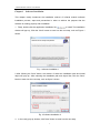
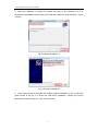
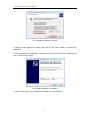
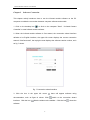
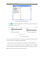
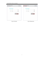
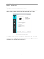
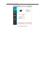
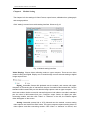
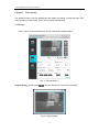
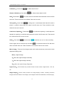
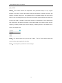
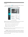
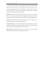
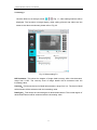
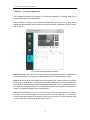
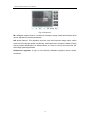
Thermal Module
Software
User Manual
Thermal Module Software User Manual
Copyright
© Wuhan Guide Infrared Co., Ltd, 2013. All rights reserved worldwide.
The trademark and model name mentioned in this manual belong to the legally
registered company.
Responsibility statement
© Wuhan Guide Infrared Co., Ltd, 2013. All rights reserved worldwide.
No parts of the manual may be copied, transmitted, transcribed, archived or
translated into any language or computer language in any form or by any
means (electronic, magnetic, optical, manual or otherwise), without the prior
written permission of Wuhan Guide Infrared Co., Ltd.
This manual is edited to help the product user to use and learn the product. We
will try our best to ensure the content precise, but still can’t ensure the content
completeness, because of the product upgrade. Thus, we reserve the right to
make any change without prior notice.
Version record:
Thermal module software user manual V1.0. Nov, 2013.
Thermal Module Software User Manual
Introduction ...................................................................................................... 0
Chapter 1 Software Installation ........................................................................ 1
Chapter 2 Software connection ........................................................................ 4
Chapter 3 Module Status ................................................................................. 7
Chapter 4 Module setting ................................................................................. 9
Chapter 5 Video Setting ................................................................................. 12
Chapter 6 Advanced Application .................................................................... 18
Chapter 7 Troubleshooting ............................................................................. 20
Introduction
This manual mainly introduce the software operation, from which you can know more
detail information of the function of thermal module.
Chapter 1: Describing the procedures of software install.
Chapter 2: Introducing the software connection chose the langue and then connects the
module.
Chapter 3: After successfully connecting the module, you can see the performance
parameters.
Chapter 4: Set up the video output parameters.
Chapter 5: Video operation.
Chapter 6: Introducing the relative algorithm inside the module.
Chapter 7: Troubleshooting.
Thermal Module Software User Manual
Chapter 1
Software Installation
This chapter mainly introduces the installation method of infrared module software
installation process, steps and precautions in order to achieve the purpose that the
software is working properly after installation.
1.Firstly, double-click the application installation file
to install. The installation
window will pop up, Click the "Next" button to enter into the next step, such as Figure 1
shows.
Fig. 1 software installation 1
2 After Clicking the "Next" button, the window of select the installation path and install
object will pop up t After selecting the installation path and object files, click the "Next"
button to enter into the next step, such as figure 2 shows.
Fig. 2 Software installation 2
3.
In the newly pop-up window, click "Next" button to enter into the next step.
1
Thermal Module Software User Manual
4.
After the installation is finished, the system will bring up two windows, one is to
complete the installation, and the other is to install the USB driver, Such as figure 3, figure
4 shows.
Fig. 3 Software installation 3
Fig. 4 Software installation 4
5.
Click "Close" button to complete the module software installation in fig. 3, then click
"Next" button in the fig. 4 to enter into USB driver installation. Hereby, the license
agreement window will pop up, such as Fig 5 shows.
2
Thermal Module Software User Manual
Fig. 5 Agreement selection window
6. Select "Accept Agreement" button, then click on the "Next" button to continue the
installation.
7. After the USB driver installation is complete, the prompt window of finish installation will
pop up such as Fig 6 shows.
Fig. 6 USB installation is completed
8. Click "Finish" button, the installation is finished, exit the installation
3
Thermal Module Software User Manual
Chapter 2
Software Connection
This chapter mainly introduces how to use the infrared module software on the PC
computer to realize the connection between computer software and module
1. Click on the desktop icon
or click on the computer "Start" --"Infrared Camera
Controller" to start infrared module software.
2. When the infrared module software is first started, the connection wizard interface
defaults to be English interface, the upper left corner displays the current connection
status is "NotConnected", the top right corner displays the software version number, such
as fig. 7 shows.
Fig. 7 Connection wizard interface
3. Click the icon in the upper left corner
documentation, such as figure 8 shows. Click
interface,Click the icon
there will appear software using
switch to the connection wizard
hide the window to the taskbar,Click the icon
software.
4
to close the
Thermal Module Software User Manual
Fig. 8 Software using documentation
4. Click
to choose ComNum and Baud rate,Click
can choose auto-connnect for
next time. Show as Fig. 9, 10, 11.
Fig. 9 Choose Com Num
Fig. 10 Choose Baud rate
Fig. 11 Set auto-connect
If choose auto-connect, the software won’t enter into the interface of connection wizard
but the next interface, but still keep the same language.
5. Click “Chinese” to choose Chinese edition, click “English” to choose English edition
6. Click “Connect” to connect module, show as fig 12. Click
to switch to connection
wizard if the module is connected. And then click “Disconnect” to disconnect module, it
appears “Disconnect” on the top left corner. Show as fig 13.
5
Thermal Module Software User Manual
Fig.12 Connect
Fig.13 Disconnect
6
Thermal Module Software User Manual
Chapter 3
Module Status
The chapter is for parameters and performance of module
1. Click “Connect” to connect module, the software will enter into the interface of module
status if succeed. It appears connection status and module model. Show as Fig 14.
Fig. 14 Interface of module status
2. It appears module information including name, shape, detector type, wave length,
resolution, function, voltage range, communication protocol etc. It also appears W-version,
IPA Temp and baud rate on the bottom. Show as fig.15.
7
Thermal Module Software User Manual
Fig. 15 Module Information
8
Thermal Module Software User Manual
Chapter 4
Module Setting
The chapter is for the settings of Video Format, output format, calibration time, photograph
and storage position.
Click “setting” to enter into module setting interface. Show as fig 16.
Fig. 16 Module setting interface
Video Display:Choose video collecting mode on upper compute. There are two video
modes: Analog and Digital. Display one of model through connect relevant analog or digital
image capture card.
Digital:Assemble Camera link pinboard onto the module, and connect with upper
computer via connecting line of camera link, the port of module is Mini-camera link. Choose
standard or Mini-camera link port via relevant image capture card on upper computer. You
also have another choice to use mini-camera link port on both sides or one side is standard
port the other is Mini-camera link port. Configure output format via digital port after
connecting module, and then click “Video” or “Advance” on the left, the real-time digital
video will appear on the screen.
Analog: Assemble camera link or VPC pinboard onto the module, connect analog
video capture card via MCX-to-BNC cable. The upper computer captures analog video via
video capture card after connecting module. Click “Video” or “Advance” on the left, and
9
Thermal Module Software User Manual
then you can watch real-time analog video.
Analog Video format: Two optional video formats: NTSC and PAL. Different format has
different flame range of digital and analog video. The module needs to be power off and
restart.
Digital Video Format: Select the proper digital video format. This setting can change
data type of digital video.
Y8: Data after AGC process, offer video channel of digital and analog video.
X16: Raw AD data before NUC
Y16: Data before AGC process, distortion on brightness and contrast
Auto Calibration Time: Set interval of shutter frequency, in minute. Interval can be short
in the start-up of core when FAP temperature is not stable; interval can be longer after
FAP temperature is stable.
External-Syn Signal: External synchronization mode. The core can receive or output
synchronization signal, as master device or slave-device.
Master: Core will send synchronized signal via external interface.
Slave: Core will receive synchronized signal via external interface. Output will be
frozen if receive no synchronized signal.
Storage File at: Image or video will be saved in this path after operation.
Timing Shoot Setting: Set interval of timing image shot on the captured video, in minute.
Continuous Shoot Setting: Set burst shooting number on the captured video.
Lens type: The core can match with five kinds of lenses.
10
Thermal Module Software User Manual
Save Setting: After changing mode and settings of core by Infrared Camera Controller
ICC, click button save setting to save the configurations as new default. If not saved, the
setting will be invalid after power off.
F-Default: Bring all settings to factory default.
Restart: Soft reboot the core.
11
Thermal Module Software User Manual
Chapter 5
Video Setting
It is described how to set the parameters and image processing, including shutter, shot,
video recording, mirror image, zoom, focus, polarity and dimming.
5.1 Setting 1 Press “video” on the left side menu and you will see the setting option:
Fig. 17 Video setting P1
Original Image:Press button
and you will see the new window as bellow
Fig.18 Original Image
12
Thermal Module Software User Manual
Calibration:Press button
to collect data for NUC.
Shutter Calibration:Press button
Shot:Press button
to collect shutter data for NUC.
for screen short and would be saved with time name in the file
save rout. There would be a new window if the rout is not exit.
Timing Shot:Press button
to timing shot. It could adjust time interval for take a
picture. It would be saved with time name in the file save rout. There would be a new
window if the rout is not exit.
Continuous Capturing:Press button
for continuous capturing. It could adjust the
quantity for capturing. It would be saved with time name in the file save rout. There would
be a new window if the rout is not exit.
Video:Press button
and the button
would be turn on for video recording;
Press it again and it would be stop recording
. It would be saved AVI file with time
name in the file save rout. There would be a new window if the rout is not exit.
Mirror image:There are four image modes and it could choose any one mode for both
digital and analog video.
None:Original image.
X:Mirror the original image horizontally.
Y:Mirror the original image vertically.
XY:Mirror the original image Diagonally.
Digital Zoom:UA330 series can provide 4 kinds of zoom modes. Original size, 1.5X, 2X,
4X.
Image Display:UA330 series provide four image display modes, including real-time
images and three kinds of test images, test images include checkerboard, horizontal gray,
13
Thermal Module Software User Manual
gray vertical.
Palette:The module detects the temperature and generates image of it by a figure
between 0 and 255. In black and white mode gray=0 displays as black, gray level 255
displays as white. Range 0 to 255 gradation can be mapped through the color lookup
table. There are usually black hot (hotter Show more black representatives) and white hot
(show more white on behalf of more heat) modes, the temperature of this simple black
and white maps, also known as polarity. Color lookup table can be also be used as color
mapping, module provides eight colors mapping, including white-hot and black hot for
analog and digital video.
Focus:For electric zoom lens, you can click " Near" ," Far" or "Auto" button to drive the
motor running, carrying electric focusing.
Zoom:Lens adjusts by continuous zoom change.
14
Thermal Module Software User Manual
5.2 Setting 2 Click the second page icon
,The image display ,calibration, shooting and
recording of video functions are the same as previous description.
Fig.19 Video setting P2
AGC:Automatic Gain Control Dimmer using online algorithm in different ways, brightness
and contrast adjustment, thereby presenting the optimal image results
Auto:Auto adjustment on the image brightness and contrast
Manual:Manually set the image brightness and contrast
Semi Auto:Manually set the image contrast
DRT:Dynamic Range Transform. In order to get optimized image performance, module
will provide linear dimming and dimming histogram.
Histogram: In histogram mode, the dynamic range compression of image date is
realized by nonlinear mapping of the image pixel gray-scale, then achieve dimming effect.
In this mode, except the Plateau Value, the values of brightness, contrast and discarded
proportion cannot be changed.
15
Thermal Module Software User Manual
Linear:In linear mode, the automatic optimization is processed according to the
brightness and contrast based on scene statistics, then adjust the pixel gray value by
using linear transformation function. Linear algorithm can update the gain and offset by
using scene statistics. In this mode, except the Plateau Value, the values of brightness,
contrast and discarded proportion can be changed.
Brightness:This reflects the whole image gray value, shown in the form of percentage.
There is a positive correlation between the brightness parameter and the overall
brightness of the image. The brightness is enhanced with the increasing brightness value.
Contrast:This reflects the whole image contrast, shown in the form of percentage. The
contrast is enhanced with the increasing parameter value.
Discarded Proportion:In this mode, discarded proportion limit the mapping range of the
original data. The greater the discarded proportion, the bigger the contrast of dimming
result, the more loss if image detail due to the image saturation.
Plateau Value:It is effective in histogram mode, range from 0~100. The contrast of
dimming result is enhanced with the increasing parameter value.
16
Thermal Module Software User Manual
5.3 Setting 3 Click the third icon at the right corner
of Fig. 17, video setting interface will be
displayed. The functions of image display, offset, taking pictures and videos are the
same as the above-mentioned, please refer to Fig. 20.
Fig. 20 Video setting P3
NR Parameter: This shows the degree of image detail recovery after noise decrease,
range from 0~255. The recovery level of image details will be enhanced with the
increasing value.
Unsharp:This shows the level of detail enhancement, range from 0~4. The level of detail
enhancement will be enhanced with the increasing value.
Detail gain:This shows the control degree of detail enhancement. The control degree of
detail enhancement will be enhanced with the increasing value.
17
Thermal Module Software User Manual
Chapter 6
Advanced Application
This chapter introduces the operation of advanced application, including adding and
saving bad pixels and other algorithms.
Click “Advance” to bring out the advanced application interface. The original image
display and the calibration are the same as before introduced. It displays AD value, please
refer to fig. 21.
Fig. 21 Advanced application interface
Add B: Add bad pixel. Move the cursor to the bad pixel position and click “Add B” button
or use button “Enter” on keyboard to add the bad pixel and improve image quality.
Save B: Save bad pixel. After adding all the bad pixels, click “Save B” button on software
interface or “Ctrl+S” button on keyboard to save the added bad pixel. When switching on
the module, it will remember the bad pixel position and replace them. If the bad pixels are
not saved, the change through ICC is only valid during one time use. When you switch on
it again, the pixels will appear at the same position.
Cursor: Cursor switching on or off. If cursor is on, the cursor will appear in the image. If
the cursor is off, it will not display. You can move the cursor by adjusting X, Y coordinates
or use the direction button on keyboard to make the cursor move. The AD sampling value
of cursor point will be indicated, please refer to fig. 22.
18
Thermal Module Software User Manual
Fig. 22 Cursor on
IIE: Intelligent Image Enhance. It enhances the edge of image. Detail enhancement level
can be adjusted by relevant parameters.
NR: Noise Remove. This algorithm removes noise and improves image quality. Noise
remove is done through double-size filtering. At the same time, it keeps the details of edge
area by weight differentiation on different areas. In a word, it not only removes noise, but
also keeps good image details.
Shutter-less algorithm: A type of non-uniformity calibration algorithm without shutter
movement.
19
Thermal Module Software User Manual
Chapter 7
Troubleshooting
Question 1: How to choose the correct COM to connect?
Answer: Open computer's device manager after the software is installed successfully.
Double click “Port” and you can see the COM that module connects through
. Choose the right COM in connection
interface to connect module.
Question 2: Click the “Video” menu, no infrared image appears.
Answer: possible reasons:
A: The video capturing card is not installed correctly or the connection with module is not
correct.
B: You don’t choose the video mode in menu “Setting”.
Please check the video capturing card is installed properly, and then, choose the video
mode in “Setting” menu.
Question 3: Photo shot and video recording file saving directory can’t be found.
Answer: Please check the file saving directory in “Setting” menu.
20