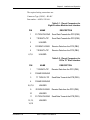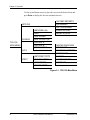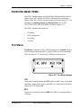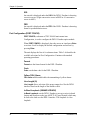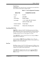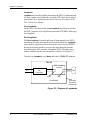
1
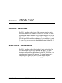
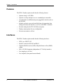
DSX-1 Passthru Option Module
User Manual
61200055L1-1D
January 2005
Table of Contents
Table of Contents
Chapter 1. Introduction
Product Overview ......................................................................................................................1
Functional description ................................................................................................................1
Features ...............................................................................................................................2
Interfaces .............................................................................................................................2
DSX-1 Passthru Option Module Specifications .................................................................3
Physical Description ..................................................................................................................4
Chapter 2. Installation
Unpack and Inspect ....................................................................................................................5
ADTRAN Shipments Include .............................................................................................5
Provided by Customer ....................................................................................................... 5
Installing the Option Module ..................................................................................................... 6
Placement of the Option Module ........................................................................................6
Power Connection................................................................................................................6
Wiring .................................................................................................................................7
Power-Up Testing and Initialization ..........................................................................................8
Successful Self-Test.............................................................................................................8
Failed Self-Test....................................................................................................................9
Operation Alarms ................................................................................................................9
Warranty and Customer Service ................................................................................................9
Chapter 3. Operation
Overview ..................................................................................................................................11
Menu Structure ..................................................................................................................11
Menu Operation ................................................................................................................11
Passthru Menu Items ................................................................................................................13
Port Status .........................................................................................................................13
CRC ....................................................................................................................13
BPV ....................................................................................................................13
XS0 .....................................................................................................................14
FER .....................................................................................................................14
Port Configuration (PORT CONFIG) .......................................................................14
Format................................................................................................................. 14
Code ....................................................................................................................14
Yellow (YEL) Alarm ..........................................................................................14
Line Length (ft) ..................................................................................................14
61200055L1-1D
DSX-1 Passthru User Manual
i
Table of Contents
In-Band Loopback (INBAND LPBACK) ......................................................... 14
Clock Source ...................................................................................................... 15
Port Utility (PORT UTIL) ........................................................................................ 15
Port Test .................................................................................................................... 15
Loopback ........................................................................................................... 16
TSU Features Used with Passthru Options ............................................................................. 17
Factory Restore ................................................................................................................ 17
Run Self-Test ................................................................................................................... 17
Appendix A. Passthru Failure Messages
Failure Messages at Power-Up ................................................................................................ 19
Passthru Alarm Messages........................................................................................................ 19
List of Figures
Figure 1-1
Figure 2-1
Figure 3-1
Figure 3-2
Figure 3-3
DSX-1 Passthru Option Module ............................................................................. 4
Installing Option Module ....................................................................................... 6
TSU 100/600 Main Menu .................................................................................... 12
Port Status Display ............................................................................................... 13
Diagram of Loopbacks ......................................................................................... 16
List of Tables
Table 2-1 Pinout Connectors for Eight-Position Modular Jack Interface .............................. 7
Table 2-2 Pinout Connectors for 15-Pin “D” Shell Interface ................................................. 8
Table 3-1 Port Configuration Parameters ............................................................................. 15
ii
DSX-1 Passthru User Manual
61200055L1-1D
Chapter 1
Introduction
PRODUCT OVERVIEW
The DSX-1 Passthru module is one of the secondary interface option
modules available for use with the ADTRAN TSU 100/600. The DSX-1
Passthru option module should be selected to provide DSX-1 access for
PBXs, or other equipment that use a DSX-1 interface. When used with a
PBX, this interface permits the combination of voice and data in a single
T1 stream. The user can select the bandwidth allocation for the DSX-1
Passthru module.
FUNCTIONAL DESCRIPTION
The DSX-1 Passthru module is designed to fit in the option slot of the
TSU 100/600 and is subject to its operation and control. The DSX-1
Passthru is configured from the front panel of the TSU 100/600 or by an
external personal computer (PC) program. The internal menus for its
configuration are a part of the DSX-1 Passthru module and are
automatically installed when the module is plugged into the unit.
61200055L1-1D
DSX-1 Passthru User Manual
1
Chapter 1. Introduction
Features
The DSX-1 Passthru option module has the following features:
•
Operates using 1 to 24 DS0s
•
Operates as a drop and pass-on or as a standard pass-on module
•
Accommodates an additional plug-on (piggyback) interface such as
the Nx56/64
•
Includes an elastic store and controlled frame slip permitting loop
timing on the network interface, as well as on the DSX-1 interface
•
Provides timing for the TSU 100/600 as an option
•
Displays menu options for easy configuration
•
Executes an extensive self-test
Interfaces
The DSX-1 Passthru option module has the following interfaces:
2
•
DSX-1 per ANSI T1.102
•
Interface connectors RJ-48C and DB-15
•
Alternate Mark Inversion (AMI) or Bipolar Return to Zero (B8ZS)
coding
•
ESF or SF (D4) formatting (independent of T1 facility interface)
•
Line length up to 655 feet
•
Line loopback (front panel/remote/inband)
DSX-1 Passthru User Manual
61200055L1-1D
Chapter 1. Introduction
DSX-1 Passthru Option Module Specifications
The DSX-1 Passthru option module conforms to the following
specifications:
61200055L1-1D
DSX-1 Interface
Per ANSI T1.102
Line Rate
1.544 Mbps
Capacity
1 to 24 DS0s (can be user configured, contiguous
or non-contiguous)
Line Codes
AMI
B8ZS
Framing Options
ESF per ANSI T1.403 and AT&T
Publication TR 54016
D4 per AT&T Publication 62411
Line Length
Up to 655 ft in 110 ft steps
Clock Source
Allows PBX to be master timing source
Tests
Power-on circuit self-test line loopback
Port loopback (internal toward MUX)
Connectors
DB-15 (female), RJ-45C
DSX-1 Passthru User Manual
3
Chapter 1. Introduction
PHYSICAL DESCRIPTION
The DSX-1 Passthru is an option module which plugs into the option slot
in the rear of the TSU 100/600. See Figure 1-1.
PASS THRU
PORT X.1
NX 56/64
PORT X.2
V.35
DSX-1
Figure 1-1. DSX-1 Passthru Option Module
The DSX-1 Passthru rear panel includes a plastic plug over a cutout for a
V.35 connector. This allows a V.35 Nx56/64 interface plug-on card, part
number 1200053L1, to be added to the DSX-1 Passthru module. The
PORT X.1 identification on the rear panel is linked to the port numbering
philosophy of the TSU 100/600 product family. The X represents the slot
number, and the .1 indicates the port number. For the TSU 100/600
application, there is only one option slot. Therefore, the port designation
for the DSX-1 Passthru port is 1.1. If added, the Nx56/64 port designation
would be 1.2. These port numbers appear in the front panel LCD menu
displays.
4
DSX-1 Passthru User Manual
61200055L1-1D
Chapter 2
Installation and Operation
UNPACK AND INSPECT
Carefully inspect the DSX-1 Passthru module for any shipping damage. If
damage is suspected, file a claim immediately with the carrier and then
contact ADTRAN Customer Service. If possible, keep the original
shipping container to ship the DSX-1 Passthru module for repair or for
verification of damage during shipment.
ADTRAN Shipments Include
The following items are included in the ADTRAN shipment:
•
DSX-1 Passthru Option Module
•
User Manual
Provided by Customer
The customer must provide the following:
•
61200055L1-1D
Cable for connection to PBX (either DB-15 or RJ type)
DSX-1 Passthru User Manual
5
Chapter 2. Installation and Operation
INSTALLING THE OPTION MODULE
Power to the TSU 100/600 should be off when installing the
DSX-1 Passthru module.
Placement of the Option Module
Figure 2-1 represents the action required for proper placement of the
option module.
1.
Remove cover plate from the TSU 100/600 rear panel.
2.
Slide the option module into the rear panel until it is positioned firmly
against the front of the TSU 100/600.
3.
Tighten the screws at both edges of option module.
TSU 100/600
Cover Plate
Option Module
Figure 2-1. Installing Option Module
Power Connection
Each DSX-1 Passthru module derives power from the base TSU 100/600
unit. Power to the TSU 100/600 is supplied by a captive 8-foot power
cord.
Wiring
The DSX-1 Passthru module offers two connectors for interfaces. Only
one is used in an installation and each is connected to the same interface.
6
DSX-1 Passthru User Manual
61200055L1-1D
Chapter 2. Installation and Operation
The required wiring connections are:
Connector Type (USOC) = RJ-48C
Part number = AMP # 555164-1
Table 2-1. Pinout Connectors for
Eight-Position Modular Jack Interface
PIN
NAME
DESCRIPTION
1
R1 TXDATA-RING
Send Data Towards the DTE (PBX)
2
T RXDATA-TIP
Send Data Towards the DTE (PBX)
3
UNUSED
4
R RXDATA-RING
Receive Data from the DTE (PBX)
5
T RXDATA-TIP
Receive Data from the DTE (PBX)
6,7,8
UNUSED
Table 2-2. Pinout Connectors for
15 Pin “D” Shell Interface
PIN
NAME
DESCRIPTION
1
T RXDATA-TIP
Receive Data from the DTE (PBX)
2
FRAME GROUND
3
T1 TXDATA-TIP
4
FRAME GROUND
5,6,7,8
UNUSED
9
R RXDATA-RING
10
UNUSED
11
12,13,
14,15
61200055L1-1D
Send Data Towards the DTE (PBX)
Receive Data from the DTE (PBX)
R1 TXDATA-RING Send Data Towards the DTE (PBX)
UNUSED
DSX-1 Passthru User Manual
7
Chapter 2. Installation and Operation
POWER-UP TESTING AND INITIALIZATION
The DSX-1 Passthru option module executes a self-test during the powerup sequence, as described in the TSU 100/600 User Manual. No
initialization input is required. Any previously configured setting for the
DSX-1 Passthru module is restored automatically upon power-up.
Successful Self-Test
The green OK LED, located with the module LEDs on the front panel,
illuminates when a successful self-test is completed and the configuration
is successfully restored. Refer to Front Panel Operation in the
TSU 100/600 User Manual.
Failed Self-Test
If the DSX-1 Passthru module fails one or more of the self-tests a message
is displayed in the LCD during power-up. Refer to TSU 100/600 User
Manual for more information. Specific failures of the DSX-1 Passthru
module are identified in the alarm listings in the Appendix A. Passthru
Failure Messages.
Operation Alarms
The red ALARM LED with the module LEDs on the front panel
illuminates when an alarm condition is detected.
8
DSX-1 Passthru User Manual
61200055L1-1D
Chapter 2. Installation and Operation
WARRANTY AND CUSTOMER SERVICE
ADTRAN will replace or repair this product within five years from the
date of shipment if the product does not meet its published specifications
or if it fails while in service. For detailed warranty, repair, and return
information refer to ADTRAN's Equipment Warranty, Repair and Return
Policy Procedure.
A Return Material Authorization (RMA) is required prior to returning
equipment to ADTRAN.
For service, RMA requests, or more information, contact one of the
numbers on the last page of this manual.
61200055L1-1D
DSX-1 Passthru User Manual
9
Chapter 2. Installation and Operation
10
DSX-1 Passthru User Manual
61200055L1-1D
Chapter 3
Operation
OVERVIEW
The DSX-1 Passthru module is controlled as part of the TSU 100/600
using the same methods as described in the user manual.
Refer to the TSU 100/600 User Manual for descriptions of the front panel
indicators and buttons.
Menu Structure
When an option card is installed in the TSU 100/600, the unit adds it to the
list of selectable options under the Port menu items. These menu items are
shaded in the limited overview of the TSU 100 menu shown in Figure 3-1.
The appendix, TSU 100 Complete Menu, of the TSU 100/600 User
Manual shows a complete menu diagram.
Menu Operation
An option module must be selected from the listing in one of the Port
menu options before its menus are applicable. With the cursor on one of
the Port menu items, press Enter to display a list of the currently installed
option modules. To activate menus for the DSX-1 Passthru option module
scroll through the list to display 1.1 DSX PT and press Enter.
Once the option module is selected, the DSX-1 Passthru menus appear as
a subset of, and operate the same as, menus for the TSU 100/600. With the
cursor on one of the TSU 100/600 four main menu choices press Enter or
a menu number to display the first two submenu items.
61200055L1-1D
DSX-1 Passthru User Manual
11
Chapter 3. Operation
Use the up and down arrows to place the cursor on the desired item and
press Enter to display the first two submenu choices.
1)NI PERF REPORTS
1)STATUS
2)NI ERRORS
3)ACTIVE ALARMS
1)NETWORK (NI)
4)VIEW HISTORY
2)UNIT
5)PORT STATUS
3)MAP XCHNG
2)CONFIG
4)MAP IN USE A (B)
TSU 100
5)DS0 MAP A
MAIN MENU
6)DS0 MAP B
1)ENTER PASSCODE
7)PORT CONFIG
2)TIME/DATE
3)UTIL
3)FACTORY RESTORE
4)REINIT UNIT
4)TEST
1)NETWORK TESTS
5)UNIT ID
2)RUN SELF TEST
6)SOFTWARE REV
3)PORT TESTS
7)PORT UTIL
4)CANCEL TEST
Figure 3-1. TSU 100 Main Menu
12
DSX-1 Passthru User Manual
61200055L1-1D
Chapter 3. Operation
PASSTHRU MENU ITEMS
The DSX-1 Passthru menus are accessed from and operated the same as
menus for the TSU 100/600. The DSX-1 Passthru items are submenu
choices of the TSU 100/600 four main menus, as shown in Figure 3-1. For
information on Factory Restore and Run Self-Test, refer to TSU
FEATURES USED WITH PASSTHRU OPTIONS on page 3-17.
The DSX-1 Passthru menu items are:
•
Port Status
•
Port Configuration
•
Port Utility
•
Port Test
Port Status
Port Status, a submenu of TSU 100/600 main menu item Status, displays
error information about the DSX-1 interface. There are four information
fields. See Figure 3-2. An asterisk (*) indicates an item is active.
Figure 3-2. Port Status Display
CRC
An asterisk is displayed under the CRC if there are CRC errors in extended
superframe format (ESF) mode. If the DSX-1 is configured for D4 Frame
format, the LCD displays n/a.
BPV
An asterisk is displayed under the BPV if the DSX-1 is detecting bipolar
violations.
61200055L1-1D
DSX-1 Passthru User Manual
13
Chapter 3. Operation
XS0
An asterisk is displayed under the XS0 if the DSX-1 Passthru is detecting
excessive zeroes. (Eight consecutive zeroes in B8ZS or 16 consecutive
zeroes in AMI.)
FER
An asterisk is displayed under the FER if the DSX-1 Passthru is detecting
frame bit synchronization errors.
Port Configuration (PORT CONFIG)
PORT CONFIG, a submenu of TSU 100/600 main menu item
Configuration, is used to configure the DSX-1 Passthru option module.
When PORT CONFIG is displayed, place the cursor on it and press Enter
to activate. Scroll to display the desired configuration and activate by
pressing Enter.
The unit displays the first of six submenu items. Table 3-A identifies the
available selections for Port Configuration. Continue with standard
operating procedures.
Format
Format sets the frame format for the DSX-1 Passthru.
Code
Code sets the data code for the DSX-1 Passthru.
Yellow (YEL) Alarm
YEL Alarm enables and disables the transmitting of yellow alarms.
Line Length (ft)
Line Length allows selection of the proper output level for the DSX-1
interface based on the length of the interface cable.
In-Band Loopback (INBAND LPBACK)
In-Band Loopback sets the DSX-1 Passthru to accept or reject in-band
loopup and loopdown codes (per ANSI T1.403 specification) which may
be sent to the card over the DSX-1 interface. This loopback is a line
loopback.
14
DSX-1 Passthru User Manual
61200055L1-1D
Chapter 3. Operation
Clock Source
Clock Source selects the clock source for transmission toward the PBX or
device connected to the DSX-1 Passthru module.
Table 3-1. Port Configuration Parameters
MENU ITEM
PARAMETER CHOICES
Format
D4, ESF
Code
AMI, B8ZS
Yellow Alarm
Enable, Disable
Line Length
1-110, 110-220, 220-330, 330-440,
440-550, 550-655, >655
In-band Loopback
Accept, Reject
Clock Source
Network (NI), Secondary (SI)
Port Utility (PORT UTIL)
PORT UTIL, a submenu of the TSU 100/600 main menu item Utilities
(UTIL) displays the current software information for each port installed in
the unit. This information is required when requesting assistance from
ADTRAN Customer Service or when updates are needed.
When PORT UTIL is displayed, place the cursor on it and press Enter to
display the first available port.
Scroll to display 1.1 DSX1 PT, and press Enter to activate. The unit
displays the option module name and the software version installed. Press
Cancel to exit or select another port.
Port Test
Port Test, a submenu of the TSU 100/600 main menu item Test, activates
tests of the selected data ports. Selecting the DSX-1 Passthru displays two
loopback tests available for this option module.
When Port Test is displayed, place the cursor on it and press Enter to
display the first available port. Scroll to select 1.1 DSX1 PT and press
Enter to activate.
61200055L1-1D
DSX-1 Passthru User Manual
15
Chapter 3. Operation
Loopback
Loopback activates the loopback function on the DSX-1 Passthru module.
All ports contain a local loopback (toward the DTE) and a port loopback
(toward the NI) as explained in the section Function Description of the
TSU 100/600 User Manual.
Line Loopback
On the DSX-1 Passthru module, Line Loopback causes data received at
the DSX-1 interface to be looped back toward the DTE (PBX) achieving a
local loopback.
Port Loopback
The Port Loopback is internal and loops all data mapped to the DSX-1
Passthru back toward the network interface on the controller. Loopback
(when used in conjunction with an external bit error rate tester (BERT)
driving the network interface) exercises the entire data path from the
network interface (NI) controller, through the DSX-1 Passthru option
module, and back out the network interface controller. See Figure 3-3.
To deactivate Loopback, select None under the 1.1 DSX1 PT submenu.
TSU 100
T1
DSX-1 Passthru
Interface
Network Interface
(NI)
(Controller)
DSX-1 PBX
PORT
LINE
LOOPBACKS
Also called
Secondary
Interface (SI)
Figure 3-3. Diagram of Loopbacks
16
DSX-1 Passthru User Manual
61200055L1-1D
Chapter 3. Operation
TSU FEATURES USED WITH PASSTHRU OPTIONS
In addition to the DSX-1 Passthru module menu items, two additional
menu items of the TSU 100/600 may be operated in conjunction with the
DSX-1 Passthru option module. These are Factory Restore and
Run Self-Test.
Factory Restore
Factory Restore, a submenu of the TSU 100/600 main menu item
Utilities (UTIL) restores the factory installed default setting for all DSX-1
Passthru option module parameters.
When Factory Restore is displayed, place the cursor on it and press Enter
to restore preset factory defaults and return to the main TSU 100/600
menu.
Run Self-Test
Run Self-Test, a submenu of the TSU 100/600 main menu item Test,
executes both the DSX-1 Passthru internal test and the TSU 100/600
internal test. The TSU 100/600 internal test is the same self-test executed
upon power-up. The results of the self-test are displayed in the LCD. For
additional information on Self-Test, refer to the TSU 100/600 User
Manual.
When Run Self-Test is displayed, place the cursor on it and press Enter to
execute the test. The unit continuously changes the display in the LCD
window until all test results are shown.
61200055L1-1D
DSX-1 Passthru User Manual
17
Chapter 3. Operation
18
DSX-1 Passthru User Manual
61200055L1-1D
Appendix A
Passthru Failure Messages
FAILURE MESSAGES AT POWER-UP
The following messages indicate a probable component failure on the
DSX-1 Passthru module:
EPROM CS
EPROM checksum error
RAM ERR
Static RAM error
PASSTHRU ALARM MESSAGES
The following messages indicate an alarm condition on the DSX-1
Passthru module:
61200055L1-1D
Red Alarm
Not able to frame data coming from the
DSX-1 interface; sometimes referred to as out
of frame (OOF)
Yellow Alarm
Remote alarm indicator (RAI) being received
from the DSX-1 interface
Blue Alarm
Receiving unframed all 1s from the DSX-1
interface, alarm indicator signal (AIS)
Loss of Signal
No signal detected from the DSX-1 interface
DSX-1 Passthru User Manual
19
Appendix A. Passthru Failure Messages
20
DSX-1 Passthru User Manual
61200055L1-1D
Product Support Information
Pre-Sales Inquiries and Applications Support
Please contact your local distributor, ADTRAN Applications Engineering, or
ADTRAN Sales:
Applications Engineering (800) 615-1176
Sales (800) 827-0807
Post-Sale Support
Please contact your local distributor first. If your local distributor cannot help, please
contact ADTRAN Technical Support and have the unit serial number available.
Technical Support
(888) 4ADTRAN
Repair and Return
If ADTRAN Technical Support determines that a repair is needed, Technical Support
will coordinate with the Customer and Product Service (CAPS) department to issue a
Return Material Authorization (RMA) number. For information regarding equipment
currently in house or possible fees associated with repair, contact CAPS directly at the
following number:
CAPS Department
(256) 963-8722
Identify the RMA number clearly on the package (below address), and return to the
following address:
ADTRAN Customer and Product Service
901 Explorer Boulevard
Huntsville, AL 35806-2807
RMA # _____________