1
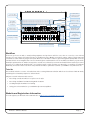
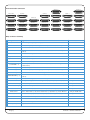
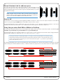
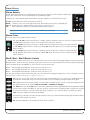
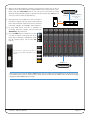
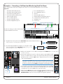
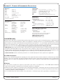
www.solidstatelogic.com
XL-Desk
The smart dumb analogue console
Owner’s Manual
XL-Desk This is SSL.
Document History
82BMLM01A
Page B
Initial Release
September 2014
XL-Desk – Owner’s Manual
Table of Contents
1. Introduction
About This User Guide
Manual Conventions
Overview
1
1
1
2
Key Features:
2
Workflow
3
Subjects covered in the Tutorials section:
3
Website and Registration Information
3
2. Installation
5
What’s in The Wooden Crate?
5
Installation Notes
5
Power Connection
5
Thermal Considerations
5
Rear Panel Connections
5
Connector Summary
5
D-sub to XLR Breakout Leads
5
3. Studio Integration
7
Connectivity Example
7
Using XL-Desk Without a Patchbay
7
Using XL-Desk With a Patchbay
8
Patchbay Guidelines
8
Line Level Input/Outputs
8
Mic Inputs
8
4. Tutorials
The VHD preamplifier
Using the preamplifier
Mono Channels
9
9
9
9
Input
9
Trim
10
Stereo Cue and Mono Auxes
11
Using the ALT input button when mixing
11
Pan Pot, Mix Bus Assignments, CUT, SOLO and Faders
11
Stereo Channels
12
500-series Rack
13
Slots 1–16
13
Slots 9–16
13
Stereo Sidechain Link for odd/even pairs
14
Slots 17-18
14
Using the 500-series Rack With or Without a Patchbay
14
Bus Compressor
15
XL-Desk – Owner’s Manual
Page C
Centre Section
16
Stereo Returns
16
Master Trims
16
Mix B, Mix C, Mix D Master Controls
16
Mix A Master Controls
17
Solo Master Section
17
Monitoring Section
18
Mon Select
18
Mon Source
18
Foldback
19
Bargraph Metering
19
How to track with XL-Desk
20
Example 1 - Recording a small ensemble in a ‘split’ console style.
20
Example 2 - Recording a Full Band and Monitoring Back Via Stems
22
Creating Headphone Mixes for Tracking
24
Using 500-series Rack Slots 9-16 with Microphone Preamplifiers
25
5 - Configuration
27
Adjusting the Level of MINI 1 and MINI 2 Monitor Outputs
27
Option DIP Switches
28
6. Appendices
29
Appendix A – Signal Flow Block Diagram
29
Appendix B – Console dimensions
30
Appendix C – Connector Pinouts
31
Appendix D – 500-series Rack Specifications
32
Appendix E – Technical & Environmental Specifications
33
Appendix F – Hardware
34
Notes
35
Page D
XL-Desk – Owner’s Manual
1. Introduction
About This User Guide
Congratulations on purchasing your Solid State Logic XL-Desk. This User Guide aims to provide you with all the necessary
information to operate the console. The Guide is arranged into the following sections:
Introduction
Installation
Studio Integration
Tutorials
Configuration
Appendices
An overview of XL-Desk’s features.
Useful information for installing XL-Desk in your studio. What’s in the box, connector summary
plus other information.
How XL-Desk connects to your existing studio equipment. How to use XL-Desk with or without
a patchbay.
How to operate XL-Desk. A rundown of all front panel operations and suggested best practices.
Information on settable options like meter scaling and latching/momentary switches.
Additional technical information for reference.
Manual Conventions
• Labelling relating to the control surface appears in Bold.
• Labelling from the rear panel appears in Bold Italic.
Notes, tips and other useful information is indicated like this.
XL-Desk – Owner’s Manual
Page 1
Overview
XL-Desk is a modern twist on the classic analogue studio console. It’s designed for tracking or mixing engineers who
require an analogue console within a DAW-centric studio, but don’t want or need the integrated DAW control and analogue
level automation other SSL console products have.
XL-Desk is in many ways a traditional 24 into 8 analogue console but it packs in an incredible collection of features. It has
20 channel strips: 16 dual input mono (switchable between main input or DAW return) and 4 stereo channels. The first
eight channels have VHD mic pre’s. There is an 18-slot 500-series rack built in that can be used for processing or mic
pre’s. XL-Desk ships with a legendary SSL Stereo Bus Compressor module in slots 17 & 18 (hard wired to Mix A). The rack
has its own dedicated high spec’ power supply.
There are four main Mix Buses (A, B, C, D) with buses B, C and D able to be summed into Mix A. The Buses and channels
can access the 500 rack and each have a separate insert point for processing. There are two mono aux sends and two
stereo return inputs. Direct outputs on every channel, stereo return and mix bus enable convenient stem printing. Each
channel has a Cue Stereo Bus section (with Pan and Level) used to provide one of the headphone mixes while tracking.
At mixdown the mono channel DAW return signals can be routed to the CUE ST bus and then summed into Mix A, so there
are 16 main faders + 16 Cue ST inputs + 4 Stereo channels providing 40 summing inputs (using the stereo returns and
insert Sum functions you can squeeze in over 50 summing inputs).
There is also a fully-featured monitoring section with bass management (3 sets of speakers + subwoofer), Foldback A and
B with individual talkbacks for headphone mixes and a built in Listen Mic input + classic compressor circuit, with its own
direct output.
Key Features:
•
20 + 1 fader, over 40 input SuperAnalogue™ SSL console
•
8-built in Variable Harmonic Drive (VHD) preamps
•
16 dual input mono channels (switchable between main input or DAW return)
•
4 stereo channels (switchable to mono for tracking)
•
The legendary Stereo Bus Compressor, with new high-pass filter sidechain
•
18-slot 500-series rack built-in, accessible from channels or mix busses
•
In addition to a 500-series rack insert each mono channel also has a standard insert point
•
4 stereo Mix Buses with their own insert points and access to the 500 rack
•
One stereo and 2 mono aux sends. Two dedicated stereo return inputs
•
Direct outputs on every channel, stereo return and mix bus for stem printing
•
Fully-featured monitoring section with bass management
•
Foldback A and B with individual talkbacks for headphone mixes
•
Built in Listen Mic input + classic compressor circuit, with its own direct output
•
AFL and Solo-In-Place solo modes, with Solo Clear and Solo Safe (Protect) modes
•
Balanced D-Sub rear panel inputs/outputs & Front panel headphones & iJack sockets
•
High quality internal PSU
Page 2
XL-Desk – Owner’s Manual
G-Series Bus
Compressor with
HPF selection
16 + 2 slot
500-series Rack
iDevice Ledge
8 x VHD
Microphone
Preamps
Dedicated Stereo
Returns
Stereo Cue,
2 Mono Auxes
Mix Bus B C D
Master Section
Monitoring Section
with Bass
Management
16 Mono channels
(2 Inputs per strip)
Communications
(Foldback/Listen)
4 Stereo/Mono Channels
Mix A Master Fader
Workflow
There are good reasons why so many leading engineers and producers still choose to mix on a console, some of them
because of sonic aspects and others because of workflow choices. Mixing out-of-the-box gives a wider sound-stage and
a distinct colouration that no plug-in can equal. We’re also told that it is easier to get a mix together quickly with a console
and that it feels more intuitive than a mouse. XL-Desk gives a full-featured console workflow, but with a project-studio
friendly footprint under 1m2. With 2 insert points on each mono channel you can mix and match rackmount and 500-series
processors to make the XL-Desk the hub of your hybrid studio world! Connect your XL-Desk to a patchbay for ultimate
flexibility, and use the direct outs from every channel and Bus to print files back into your DAW for easy mix revisions.
Tutorials
This manual includes a series of detailed tutorials covering different workflow which can be achieved with XL-Desk,
including the connectivity required to achieve them.
Subjects covered in the Tutorials section:
•
Recording a small ensemble in a ‘split’ console style
•
Recording a full Band and Monitoring Back via Stems
•
Creating Headphone Mixes for Tracking
•
Using 500-series Rack Slots 9-16 with Microphone Preamplifiers
Website and Registration Information
You can register your XL-Desk on the SSL website: at http://store.solidstatelogic.com/user
XL-Desk – Owner’s Manual
Page 3
Rear Panel Audio Connectors
MIX A B C D SEND
MISC INPUTS
MIX A B C D RETURN
MISC OUTS 1
MIX A B C D OUT
AJ
LINE INPUT 9 - 16
MIC INPUT 1 - 8
500 SEND 9 - 16
DAW INPUT 9 - 16
500 SEND 1 - 8
DAW INPUT 1 - 8
MONITOR OUTS
500 SLOT IN 9 - 16
INSERT SEND 9 - 16
500 SLOT IN 1 - 8
INSERT SEND 1 - 8
MISC OUTS 2
STEREO INPUT 1 - 4
500 SLOT OUT 9 - 16
INSERT RETURN 9 - 16
500 SLOT OUT 1 - 8
INSERT RETURN 1 - 8
CJ
STEREO OUT 1 - 4
500 RETURN 9 - 16
CHANNEL OUT 9 - 16
500 RETURN 1 - 8
CHANNEL OUT 1 - 8
DB25 Connector Summary
DB25 Connector
Signals
MIC INPUT 1 - 8
VHD microphone preamplifier inputs
DAW INPUT 1 - 8
Line-level inputs (connect outputs 1-8 from your audio interface here)
INSERT SEND 1 - 8
Notes
Main Insert Sends for mono channels 1-8
INSERT RETURN 1 - 8
Main Insert Returns for mono channels 1-8 (associated with INS front panel
button)
CHANNEL OUT 1 - 8
Direct Channel Outputs for mono channels 1-8
500 SEND 1 - 8
Secondary Insert Sends for mono channels 1-8
500 SLOT IN 1 - 8
500-series rack inputs 1-8
500 SLOT OUT 1 - 8
500-series rack outputs 1-8
500 RETURN 1 - 8
Secondary Insert Returns for mono channels 1-8 (associated with 500 front
panel button)
LINE INPUT 9 - 16
Line-level inputs
DAW INPUT 9 - 16
Line-level inputs (connect outputs 9-16 from your audio interface here)
INSERT SEND 9 - 16
Main Insert Sends for mono channels 9-16
INSERT RETURN 9 - 16
Main Insert Returns for mono channels 9-16 (associated with INS front panel
button)
CHANNEL OUT 9 - 16
Direct Channel Outputs for mono channels 9-16
MONITOR OUTS
Loudspeaker outputs for monitoring: Main L, R; Mini 1L, 1R; Mini 2L, 2R; Sub
DB25 to XLR-M loom
Line-level inputs for the stereo channels
DB25 to XLR-F loom
Direct channel outputs for the stereo channels
DB25 to XLR-M loom
MISC INPUTS
Stereo Return In 1L, 1R; Stereo Return In 2L, 2R; External Input L, R
DB25 to XLR-F loom
MISC OUTS 1
Stereo Return Out 1L, 1R; Stereo Return Out 2L, 2R; Meter L, R; Listen Mic Out
DB25 to XLR-M loom
MISC OUTS 2
Foldback Out AL, AR; Foldback Out BL, BR; Cue Stereo L, R; Aux Out 1, 2
DB25 to XLR-M loom
STEREO INPUT 1 - 4
STEREO OUT 1 - 4
MIX A B C D SEND
Mix Insert send for the 4 stereo mix busses
MIX A B C D RETURN
Mix Insert return for the 4 stereo mix busses
MIX A B C D OUT
AJ and CJ
Page 4
Stereo mix bus outputs
Top secret!
XL-Desk – Owner’s Manual
2. Installation
WHAT’S IN THe WOODeN CRATe?
•
•
•
•
Not to scale!
The console
Mains lead
D-Sub – D-Sub cables (x4)
Installation Guide
5A
INSTALLATION NOTeS
Power Connection
The console is fitted with auto-sensing power supplies which will function at any voltage from 100 to 230 volts ±10%
without adjustment.
Three IEC mains power-leads may be supplied: one with a UK 3-pin fused plug fitted, one with US-style 3-pin mains plug
fitted and one with a european 3-pin plug. Please select the appropriate lead for the local power outlets.
Thermal Considerations
The console is cooled by fan-assisted convection from the front inlet (below the front buffer) to the exit in the rear panel.
It is VERY important that these ventilation grills are not obstructed in any way – particularly if the console is going to be
mounted into additional furniture.
CAUTION. The heatsink fins on the console rear panels can reach temperatures of approximately 30 degrees
Celsius above the ambient room temperature.
Rear Panel Connections
All connections to the console – apart from the headphone and iJack sockets – are located on the rear panel.
•
•
•
•
D-Sub connectors are all high-quality 25-way female
The screw pillars utilise the standard UNC-440 thread
All connections are balanced and are wired to the AES59 Analogue Standard (also known as the Tascam standard)
XLR connectors are wired with pin 2 ‘hot’
Connector Summary
Analogue I/O
Monitor L
Monitor R
Listen In
USB
Power Supply
25-way D-Type sockets
3-pin XLR-Male
3-pin XLR-Male
3-pin XLR-Female
Type-B chassis socket
IEC320 3-pin connector
Refer to table on page 4
Main LS Left*
Main LS Right*
Listen Mic Input
Diagnostics (SSL Service use)
* These signals also appear on the MONITOR OUTS DB25 connector
MONITOR L
MONITOR R
USB
1
LISTEN IN
2
3
1
Refer to Appendix C, page 31 for connector pinout information.
D-sub to XLR Breakout Leads
When connecting directly to external equipment – amplifiers, effects units, meters etc. – adapter leads that convert the
console’s DB25 female connectors into 8 x XLRs are likely to be useful. Refer to the table on page 4 for notes on where
these adapter leads might be required.
XL-Desk – Owner’s Manual
Page 5
Studio Integration Diagram
3 sets of Speakers plus Subwoofer
DAW
Outboard Mic Preamps
8x
MADI
AlphaLink MX
MX
POWER
MADI
RATE
CLOCK
LEVEL
OUTPUTS
INPUTS
MADI
RATE
CLOCK
LEVEL
INPUTS
OUTPUTS
16 - 4
MX
POWER
4 - 16
MX
MADI
POWER
VHD Mic In
1–8
Line In
9–16
Monitor
Outputs
DAW Line
Inputs
Stereo Channel
Inputs
RATE
CLOCK
LEVEL
INPUTS
OUTPUTS
4 - 16
Channel
Direct Outs
Mix Bus
Outputs
Stereo return
Outputs
Headphones
MP3 Player
Foldback
Outputs A & B
Insert
Sends
Insert
Returns
Cue/Aux
Stereo
Sends Return Input
Listen Mic
Live Room
2x
Outboard Rack Gear
Page 6
Outboard FX
(Reverb/Delays)
XL-Desk – Owner’s Manual
3. Studio Integration
CONNeCTIvITy eXAMPLe
See diagram on page 6 for an example of how other studio equipment can be connected to XL-Desk.
USING XL-DeSK WITHOUT A PATCHBAy
If using XL-Desk without an external patchbay, it is necessary to use the 4 included short D-Sub cables (shipped with XLDesk) to link the following connections on the rear:
1
500 SEND 1-8
to
500 SLOT IN 1-8
2
500 SLOT OUT 1-8
to
500 RETURN 1-8
3
500 SEND 9-16
to
500 SLOT IN 9-16
4
500 SLOT OUT 9-16
to
500 RETURN 9-16
500 SEND 9 - 16
MONITOR OUTS
STEREO INPUT 1 - 4
STEREO OUT 1 - 4
Link 3
500 SLOT OUT 9 - 16
Link 4
Send from channel goes to 500 rack slot input
500 rack slot output goes to channel return
Send from channel goes to 500 rack slot input
500 rack slot output goes to channel return
DAW INPUT 9 - 16
INSERT SEND 9 - 16
INSERT RETURN 9 - 16
CHANNEL OUT 9 - 16
500 SEND 1 - 8
Link 1
500 SLOT OUT 1 - 8
Link 2
DAW INPUT 1 - 8
INSERT SEND 1 - 8
INSERT RETURN 1 - 8
CHANNEL OUT 1 - 8
Adding these connectors will link the insert points associated with the 500 button, to and from the 500-series rack.
XL-Desk – Owner’s Manual
Page 7
USING XL-DeSK WITH A PATCHBAy
For ultimate flexibility, XL-Desk can connect to a standard 25-way D-Sub patchbay. One of the advantages of using a
patchbay is that it will allow patching between 500 rack modules.
The image below is a suggested layout for console connection using 4 patchrows.
1
2
B
1
CHANNEL VHD MIC INPUTS
2
3
4
5
6
7
2
3
4
5
6
C
1
2
3
4
5
6
D
1
2
3
4
5
6
E
1
2
3
4
5
6
F
1
2
3
4
5
CHANNEL INSERT RETURNS
6
7
8
9
10
11
12
13
14
15
16
16
17
18
23
24
25
G
1
2
3
4
5
CHANNEL DIRECT OUTPUTS
6
7
8
9
10
11
12
13
14
15
16
1L
STEREO CHANNEL OUTPUTS
1R 2L 2R 3L 3R 4L
4R
STEREO RET OUT
1L
1R 2L 2R
H
1
5
DAW INPUTS
7
8
9
10
17
DAW INPUT
19
20
21
22
1
1
1
1
1
1
1
1
2
2
2
2
2
2
2
2
3
3
3
3
3
3
3
3
3
4
4
4
4
4
4
4
4
4
5
5
5
5
5
5
5
5
6
6
6
6
6
6
6
6
6
7
INPUT LINES
9
8
10
A
7
7
8
9
8
9
8
9
10
11
11
12
12
13
13
14
14
15
15
CHANNEL LINE INPUTS
10
11
12
13
14
15
10
16
16
16
11
12
13
14
15
CHANNEL INSERT SENDS
7
8
9
10
11
12
13
14
15
16
11
12
13
14
15
16
OUTBOARD OUTPUTS
7
8
9
10
11
12
13
14
15
16
7
8
9
10
7
8
9
10
OUTBOARD INPUTS
7
8
9
10
7
7
8
8
9
9
10
10
7
8
9
10
7
8
9
10
11
11
11
11
11
11
11
12
12
12
12
12
12
12
13
13
13
13
13
13
13
14
14
14
14
14
14
14
15
15
15
15
15
15
15
16
16
16
16
16
16
16
1
17
1
17
1
17
1
17
1
17
1
17
17
2
18
2
18
2
18
2
18
2
18
2
18
18
18
3
19
3
19
3
19
3
19
3
19
3
19
4
20
4
20
4
20
4
20
4
20
4
20
5
21
5
21
5
21
5
21
5
6
7
8
9
22
23
24
25
22
23
24
25
10
26
11
27
28
13
29
14
30
DAW OUTPUTS
15
16
17
18
31
32
33
34
19
20
35
36
21
37
22
38
23
24
4R
39
40
CHANNEL DAW INPUTS
6
7
8
9
10
11
12
13
14
15
16
1L
STEREO CHANNEL INPUTS
1R 2L 2R 3L 3R 4L
34
35
38
39
6
500 SLOT SEND 1 – 16
7
8
9
10
11
12
13
14
15
16
1L
1R
MIX INSERT SEND
2L 2R 3L 3R
4L
4R
6
500 SLOT INPUT 1 – 16
7
8
9
10
11
12
13
14
15
16
17
18
19
OUTBOARD IN
20
21
22
23
24
12
13
14
15
16
17
18
OUTBOARD OUTPUTS
19
20
21
22
23
22
22
6
26
27
23
24
25
26
27
23
24
25
26
27
500 SLOT OUT 1 – 16
7
8
9
10
22
5
500 SLOT RETURNS 1 – 16
6
7
8
9
10
11
22
19
20
21
22
19
20
21
22
23
23
23
23
24
24
24
24
25
25
1
25
26
11
21
21
12
26
26
2
26
27
27
28
28
28
28
12
28
29
29
29
29
13
29
30
30
30
30
14
30
METER
L
R
27
28
29
30
27
28
29
30
USER INPUT
3
4
5
6
31
31
31
31
15
31
LSN
OUT
31
7
31
32
32
32
32
16
32
32
8
32
33
33
41
42
43
44
45
46
47
48
F/B A OUT F/B B OUT
L
R
L
R
L
43
44
45
24
1L
FX OUT
1R 2L
2R
AL
MIX INSERT RETURN
AR BL BR CL CR DL
DR
ST RETURN IN
1L
1R 2L 2R
AL
DR
MAIN LS
L
R
32
AMP IN
L
R
33
39
35
36
37
38
39
34
35
36
37
38
39
AR
BL
MIX OUT
BR CL
CR
DL
26
DAW INPUT
27
28
29
30
34
34
35
35
36
37
36
37
38
38
39
31
39
40
40
40
40
AMP IN
L
R
41
41
AMP IN
L
R
42
43
42
43
44
46
CUE
R
42
25
38
32
41
33
37
40
31
40
33
36
39
30
45
45
34
38
29
44
44
33
37
28
43
43
35
36
40
27
42
42
34
35
37
26
41
41
33
34
36
25
L
MINI A
L
R
1
48
AUX
2
46
47
48
46
47
48
FX IN
R
1
EXT SRC
1
2
44
47
2
45
46
47
48
45
46
47
48
EXT IN
L
R
MINI B
L
R
SUB
M
M
41
42
43
44
45
46
47
48
41
42
43
44
45
46
47
48
AMP IN
L
R
AMP IN
L
R
AMP IN
L
R
Notes
1. Row AB 1–8 should be fully normalled (or could be left un-normalled – requiring the use of patchcords)
2. All other rows should be half-normalled apart form the parallels at B 41–48
3. The parallels at B 41–48 can be created by using a DB25 Mult plug
Patchbay Guidelines
Line Level Input/Outputs
All analogue inputs and outputs can be connected via a patchbay. It is recommended that the cable shield is connected
at the console end and disconnected at the patchrow to avoid ground loops. Wiring to the installation should normally
have the shield connected to the patch row. The shield connection of all jacks should be linked together (note that patch
rows with solid metal front panels will automatically do this) and then linked to a common star point on the patchbay.
This starpoint can then be returned – via a thick grounding cable (6mm sq. or greater) – to the chassis stud on the rear of
the console. This will reduce the risk of earth loops within the installation.
The screen pins of all analogue inputs and outputs – with the exception of the microphone inputs – are connected directly
to the chassis of the XL-Desk.
Mic Inputs
If Microphone inputs are to be connected via a patchbay, the type of patchrow used should be of the insulated variety
where the jack screens are not connected to the main body of the patchrow – there are commercially available patchrows that meet this requirement. The ground connection from each microphone must be linked through the patch jacks
to the MIC INPUT 1-8 connector on the back of the console without interruption.
Page 8
XL-Desk – Owner’s Manual
4. Tutorials
THe vHD PReAMPLIFIeR
XL-Desk has 8 Variable Harmonic Drive preamplifiers built-in.
The red pot provides up to +75 dBs of gain, whilst the black pot provides a variable mix of 2nd to 3rd harmonics (once the
vHD button is engaged).
The outputs of these 8 preamplifiers feed the main inputs of mono channels 1-8.
vHD
HI-Z
+48v
PAD
Engages the Variable Harmonic Drive circuit within the preamplifier
Switches the preamplifier impedance from 1.2K Ω to 10K Ω
Applies phantom power
Applies 20 dBs attenuation before the signal enters the preamplifier
Using the preamplifier
When the vHD button is not engaged, the preamplifier has been designed to give a transparent
sound, great for sources such as acoustic guitars, vocals and strings.
When the vHD button is pressed, the preamplifier can be driven to give a wide-range of overdriven
sounds, ranging from subtle to... well, not so subtle! Drums and electronic instruments can often
benefit from VHD colouration.
The best way to drive the VHD preamplifier is to increase the input gain (red pot) whilst using the
Line Trim pot to reduce the overall level and not clip the channel output. Remember, it’s the input
to the preamplifier that likes being driven. From this point, adjust the harmonics to fine-tune the
desired sound.
If sending pre-recorded audio back through the preamplifiers, you will find it useful to engage the
input PAD. This will lower the level at which the signal hits the preamplifier.
MONO CHANNeLS
Input
Each channel of XL-Desk has two inputs, switchable by pressing the DAW button.
The primary input on channels 1-8 is the VHD microphone preamplifier. This is labelled as MIC INPUT
1-8 on the rear panel. Pressing the DAW button will instead source the line-level input labelled DAW
INPUT 1-8 on the rear panel.
The primary input on channels 9-16 is the line-level input labelled LINE INPUT 9-16 on the rear panel.
Pressing the DAW button will instead source the line-level input labelled DAW INPUT 9-16 on the
rear panel.
Typically, the outputs from your DAW’s audio interface/converter would be connected to DAW INPUT
1-8 and DAW INPUT 9-16. Some people may like to think of these as ‘monitor returns’. LINE INPUT
9-16 may be connected to outboard microphone preamplifiers (to extend the number of
preamplifiers already available) or perhaps a line-level instrument.
Mono
Channels
1–8
XL-Desk – Owner’s Manual
Mono
Channels
9 – 16
Page 9
Trim
The black pot provides +/- 20dBs of trim. Use this to control the output when driving the VHD preamplifier
circuit. Alternatively use Trim to drive into inserted outboard compressors. Trim will function on the
currently selected input to the channel.
Below the trim pot is a tri-colour signal present LED. The
three audio levels are indicated are:
LED
Green:
+24dB Scale
+18dB Scale
–24 dBu
–24dBu
Yellow:
+4 dBu
0dBu
Red:
+21 dBu
+ 16 dBu
Remember it is possible to rescale the X-Desk’s metering to a +18dBu (as opposed to the standard +24 dBu)
with the option DIP switches on the rear panel. See DIP Switch Selection on page 28.
When pressed, the input labelled DAW INPUT 1-8 or DAW INPUT 9-16 on the rear-panel is sourced.
DAW
The following buttons function on the currently selected input to the channel:
Ø
500
INS
CHOP
POST
Polarity inversion for the channel
Engages the insert point normally associated with the in-line 500-series rack slot*
Engages the insert point normally associated with an external piece of outboard equipment. The rear panel
connectors are labelled INSERT SEND/RETURN.
Makes the direct channel output post-fader, instead of pre-fader
* Please refer to the 500-series Rack section of this chapter for more information regarding signal flow to
and from the rack.
Page 10
XL-Desk – Owner’s Manual
Stereo Cue and Mono Auxes
XL-Desk has a STeReO CUe bus which can be sent to using the green level pot and panned with the blue pot. The Stereo
Cue is switchable between pre or post-fader, on a per-channel basis using the POST button. During tracking, the Stereo
Cue could be used for an artist’s headphone mix. For mixing, the Stereo Cue could be used to send to an FX unit for
reverb/delay.
Aux 1 and Aux 2 are mono sends, which would normally be connected to outboard FX processing like reverbs and delays.
Aux 1 is also suitable for the creation of a second headphone mix. Aux 1 and Aux 2 are globally switchable between pre
or post-fader, in the MASTeR TRIMS section.
Using the ALT input button when mixing
When mixing, the STeReO CUe can source the input that is currently not selected as the main input to
the channel. This is done by pressing the ALT (alternate input) button. For example, if DAW is selected
as the main input to channel 9, then pressing ALT would bring LINE INPUT 9 into the Stereo Cue for that
channel. The green pot is used to control level whilst the blue pot positions the source within the Stereo Cue
field. Finally, the TO A button underneath the STeReO CUe MASTeR TRIM can be used to inject the all signals
on the Stereo Cue bus into Mix Bus A. Using this method will provide an extra 16 inputs to the mix.
Pan Pot, Mix Bus Assignments, CUT, SOLO and Faders
At the base of XL-Desk you will find traditional analogue desk functions.
The blue PAN pot controls the channel’s left/right positioning in the stereo field when assigned to one
or more stereo mix bus.
A B C D buttons will route the channel to the relevant stereo mix bus: Mix A, Mix B, Mix C, Mix D.
CUT mutes the channel’s output.
SOLO - The exact action of the solo is dependant on the desk’s current solo mode: Solo-in-place
(SIP) or AFL (After-Fader-Listen). See page 17 for additional information.
The space below the SOLO button provides enough room to stick the traditional strip of electrical tape
to write track names on.
The 100mm analogue fader provides a gain control for feeding the selected stereo busses and/or direct
channel output if CHOP POST is selected.
XL-Desk – Owner’s Manual
Page 11
STeReO CHANNeLS
XL-Desk provides 4 stereo input channels located immediately to the left
of the Mix A master bus fader.
The stereo channels on XL-Desk differ from the mono in the following ways:
• Stereo channels have one stereo input per strip
• Two signal present LEDs are provided for monitoring incoming left
and right signals
• No insert points
• The pan pot becomes a balance pot when operating in stereo.
Each stereo channel can operate in mono by pressing the MONO button
next to the pan pot. This is useful for heavy tracking sessions, where you
need extra mono inputs to feed these channels – the outputs from extra
preamplifiers, for example.
Page 12
XL-Desk – Owner’s Manual
500-SeRIeS RACK
Slots 1–16
Built into the penthouse of XL-Desk is a 500-series rack. This rack is a 16 + 2 slot design. The image shows the
rack filled with SSL modules – but of course, this could be a selection of 500-series modules from other
manufacturers. The first 16 slots are lined up with the 16 mono channels, and pressing the button labelled 500
will activate the insert return, bringing the 500-series processing into that channel...
Slots 9–16
...However, the 4 stereo mix busses (A B C D) are able to steal rack slots 9-16 to use as extra processing:
Mix A can steal 500 slots 9–10
Mix B can steal 500 slots 11–12
Mix C can steal 500 slots 13–14
Mix D can steal 500 slots 15–16
The slots are stolen by pressing the 500 button in the master controls section for each mix bus. See the following section
for more information.
500 Slots 1 – 8
500 Slots 9 – 16
500 Button
(Busses B C D)
500 Button
(Bus A)
XL-Desk – Owner’s Manual
Page 13
Stereo Sidechain Link for odd/even pairs
For 500-series modules that support the ability to link sidechains across
odd/even module slots, every odd numbered rack slot has a jumper on the
rack’s backplane that can be moved from position ‘A’ (Not Linked), to position
‘B’ (Linked Sidechain).
B A
B A
Position
A
Position
B
NOTE. To gain access to these links, you will need to remove the
module (and any adjacent ones that make changing this awkward).
Please ensure that the POWER TO THE CONSOLE IS OFF.
Slots 17-18
The final two slots are reserved for the legendary SSL Bus Compressor. These slots can only be inserted over the Mix A
stereo bus by pressing the COMP button in the Mix A master controls section.
Don’t forget that this is just a standard two-slot 500 rack space, so you can remove the Bus Compressor and use it
anywhere else in the rack if desired or use a different 500-module in place of the Bus Compressor!
Using the 500-series Rack With or Without a Patchbay
The rear panel of XL-Desk allows access to the inputs and outputs of the 500-series rack. These D-Subs are labelled: 500
SLOT IN 1-8, 500 SLOT IN 9-16, 500 SLOT OUT 1-8 and 500 SLOT OUT 9-16.
If using XL-Desk without an external patchbay, it is necessary to use the 4 included short D-Sub cables (shipped with XLDesk) to link connections on the rear. Refer to the additional information on page 7.
The thing to remember is that the 500 button is, in reality, a second insert point which can route the signal
out of and back into the channel. By connecting the short D-Sub patch cables, as described on page 7, the
signal is routed into the associated 500-series rack slot and back again – e.g. Channel 1’s 500 button
inserts Slot 1 from the 500 rack.
For ultimate flexibility, remove the short D-Sub patch cables and link those connectors discretely to a patchbay. This will
allow routing to be made between modules, so that more than one 500 processor slot can be used on a single channel.
LINE INPUT 9 - 16
500 SEND 9 - 16
DAW INPUT 9 - 16
MIC INPUT 1 - 8
500 SEND 1 - 8
DAW INPUT 1 - 8
16
500 SLOT IN 9 - 16
500 SLOT OUT 9 - 16
500 SEND 9 - 16
500 RETURN 9 - 16
500 SLOT IN 9 - 16
INSERT SEND 9 - 16
LINE INPUT 9 - 16
INSERT RETURN 9 - 16
DAW INPUT 9 - 16
CHANNEL OUT 9 - 16
INSERT SEND 9 - 16
500 SLOT IN 1 - 8
500 SLOT OUT 1 - 8
500 SEND 1 - 8
500 RETURN 1 - 8
500 SLOT IN 1 - 8
INSERT SEND 1 - 8
MIC INPUT 1 - 8
INSERT RETURN 1 - 8
DAW INPUT 1 - 8
CHANNEL OUT 1 - 8
INSERT SEND 1 - 8
16
16
16
16
INSERT RETURN 9 - 16
500 SLOT OUT 1 - 8
INSERT RETURN 1 - 8
CHANNEL OUT 9 - 16
500 RETURN 1 - 8
CHANNEL OUT 1 - 8
1
2
18
2
3
19
3
19
3
4
20
4
20
4
5
21
5
21
5
17
18
19
20
21
16
17
18
19
20
21
16
16
16
16
16
16
500 RETURN 9 - 16
1
17
2
18
16
16
500 SLOT OUT 9 - 16
1
17
16
16
1
1
2
2
3
3
4
4
5
5
17
18
19
20
21
17
18
19
20
21
1
2
3
4
5
F/B A OUT F/B B OUT LSN
1
17
1
17
2
18
2
18
3
19
3
19
4
20
4
20
5
21
5
21
F/B A OUT F/B B OUT LSN
Page 14
6
500 SLOT SEND 1 – 16
7
8
9
10
11
6
500 SLOT INPUT 1 – 16
7
8
9
10
11
22
22
6
24
25
26
27
28
23
24
25
26
27
28
500 SLOT OUT 1 – 16
7
8
9
10
11
22 500
23 SLOT
24 SEND
25 1 26
– 16 27
6
6
7
8
9
10
11
500 SLOT RETURNS 1 – 16
23 24 25 26 27
7
8
9
10
11
22
22 500
23 SLOT
24 INPUT
25 1 26
– 16 27
6
22
6
22
6
7
23
8
24
METER
9
25
10
26
MAIN LS
500 SLOT OUT 1 – 16
7
8
9
10
11
27
12
12
28
12
28
12
11
13
29
13
29
13
14
30
14
30
14
30
14
15
31
15
31
15
31
15
31
15
16
32
16
32
16
32
16
32
16
STEREO CHANNEL DIRECT OUTP
1L
33
17
33
1L
33 STEREO CHANNEL DIRECT OUTP
1L
ST RETURN IN
33
1L
30
31
32
33
28
29
30
31
32
33
12
12
24
25
26
27
28
23
24
25
26
27
28
MAIN LS
13
29
14
30
29
23
METER
13
29
28
MINI A
500 SLOT RETURNS 1 – 16
7
8
9
10
11
22
12
23
12
MINI A
13
14
MINI B
13
29
13
29
14
30
14
30
MINI B
15
16
SUB
15
31
15
31
16
32
16
32
SUB
XL-Desk – Owner’s Manual
17
ST RETURN OUT
1L
33
1L
ST RETURN IN
33
ST RETURN OUT
Bus Compressor
Included with every XL-Desk is the legendary SSL Bus Compressor for 500-series. It is a simple
unit with a simple purpose; it makes complete mixes sound bigger, with more power, punch
and drive. It brings cohesion and strength to your mix without compromising clarity. The
updated design now includes a notched high-pass filter in the sidechain.
The compressor sidechain controls are straight-forward and hopefully require little
explanation. The ATTACK, RATIO and ReLeASe and HPF (High Pass Filter) controls are multiposition switches; the THReSHOLD and MAKe-UP controls are continuously variable
potentiometers. The illuminated compression meter above the unit displays gain reduction
for the compressor.
XL-Desk – Owner’s Manual
Page 15
CeNTRe SeCTION
Stereo Returns
Traditionally, Stereo Returns are usually fed from the outputs of FX units such as Reverbs and Delays.
They could, however be used as extra inputs for any line-level signal.
XL-Desk has 2 Stereo Return inputs each with its own blue balance pot and black level control.
ST CUe
MONO
ABCD
AFL
Routes the stereo return to the Stereo Cue bus.
Creates a mono sum of any signals present. The balance pot becomes a left-right pan.
Routes the Stereo Return signal to any selection of stereo busses.
Allows the stereo return to be auditioned in the studio monitors.
Remember to turn the AFL master pot up in the monitoring section first!
Master Trims
This section provides useful level trim controls.
The green ST CUe level pot provides up to +10dBs of gain for the Stereo Cue bus. This pot is centre-indented at
0dB. AFL allows the Stereo Cue bus to be auditioned in the studio monitors.
The green AUX 1 level pot provides up to +10dBs of gain for the Aux 1 bus. This pot is centre-indented
at 0dB. PRe globally sets Aux 1 sends be pre-fader. AFL allows the Aux 1 bus to be auditioned in the
studio monitors.
The green AUX 2 level pot provides up to +10dBs of gain for the Aux 2 bus. This pot is centre-indented
at 0dB. PRE globally sets Aux 2 sends be pre-fader. AFL allows the Aux 2 bus to be auditioned in the
studio monitors.
Mix B, Mix C, Mix D Master Controls
3 of the XL-Desk’s 4 stereo mix busses are controlled in this section. The controls that apply to Mix B, C and D are identical.
Mix Busses B, C and D do not have dedicated 500-series rack slots associated with them. However, by pressing the 500
button, XL-Desk allows each Mix Bus to ‘steal’ a pair of slots from the rack:
Mix B – Pressing 500 allows Mix B to steal 500-series rack slots 11-12
Mix C – Pressing 500 allows Mix C to steal 500-series rack slots 13-14
Mix D – Pressing 500 allows Mix D to steal 500-series rack slots 15-16
This way, processing modules inserted into the 500-series rack can be swapped between use on mono channels or stereo
mix busses. (For additional information see diagram on page 13.)
When a pair of 500-series rack slots are stolen, they are unavailable for use on the mono channels they are
normally associated with. They can be released back to these by simply pressing the 500 button again.
INS engages the insert point normally associated with an external piece of stereo outboard equipment. The
rear panel connectors are labelled MIX A B C D SEND and MIX A B C D RETURN.
The SUM button, below the INS button, sums the Insert Return and the original Mix Bus feed together providing
a direct stereo input to the Mix bus. This also provides a clever way of ‘instant parallel compression’ if using
an outboard compressor. Use the output gain of the compressor to control the level of compressed signal.
TO A routes the output of the mix bus into Mix A.
The black pot controls the overall level of the mix bus. This pot is centre indented at unity gain. At full clockwise
rotation +10dBs of gain is provided.
AFL allows the Mix Bus to be auditioned in the studio monitors.
Page 16
XL-Desk – Owner’s Manual
Mix A Master Controls
Typically, the output of Mix A would be used as the final stereo output from which the final mix would be
printed back into the DAW.
Mix A has its own dedicated 100mm heavy-duty fader, with 0dB gain at the very top of the fader travel. In
addition, the following buttons can be found above the MIX A fader:
The 500 button allows Mix A to steal processing slots 9 -10 of the 500-series rack.
INS engages the insert point normally associated with an external piece of stereo outboard equipment.
The rear panel connectors are labelled MIX A B C D SEND and MIX A B C D RETURN.
The SUM button below the INS button, sums the Insert Return and the original Mix Bus feed together
providing a direct stereo input to the Mix bus. This also provides a clever way of ‘instant parallel
compression’ if using an outboard compressor. Use the output gain of the compressor to control the level
of compressed signal.
The button labelled COMP engages the in-built SSL Bus Compressor. In true SSL tradition, the send is always
active, so be sure that both the COMP button and the IN button on the compressor itself are active, as the
compression needle will be moving regardless of whether it is in circuit or not.
Solo Master Section
CLeAR - Cancels any solos
SAFe - Enters/exits Solo Safe setup mode. This is useful when you want
to protect channels from being cut when a solo is made.
A prime example would be a vocal reverb return.
This presumes you are in Solo-In-Place mode.
Imagine a dry vocal is routed into channel 8 of the
desk. From this, Aux 1 is being used to send
signal into an outboard reverb unit. The output of
this reverb unit is being sent into channel 2324(stereo fader). The desired effect is that when
channel 8 is solo’d, channel 23-24 is not cut and
the listener ‘automatically’ hears the reverb
return without needing to pressing the solo
button on channels 23-24.
AFL - When this button is lit, the desk operates in
After-Fader-Listen (AFL) solo mode.
To Solo Safe channels do the following:
1. Press the SAFe button to enter the setup mode
2. Press the SOLO button on desired channels (they flash)
3. Press the SAFe button to exit this setup mode.
Now, these channels are not cut when a solo is made.
To remove channels from Solo Safe mode do the following:
1. Press the SAFe button to enter setup mode.
2. Any channels that are Solo Safe’d will flash their SOLO
buttons
3. Press any flashing SOLO buttons to remove them from
Solo Safe mode
4. Press the SAFe button to exit.
The difference between Solo-In-Place (SIP) and After-Fader-Listen (AFL) solo modes:
SIP – XL-Desk’s default soloing mode. When a solo is made, all other channels are CUT.
AFL – Press the AFL button to switch XL-Desk into AFL solo mode. When a solo is made, the signal(s) is sent to the AFL bus. The
monitoring section will automatically source the AFL bus if a solo is made in this mode. Ensure the AFL bus master level
control is turned up. AFL may be useful when recording/printing stems because soloing a channel does not cause other
channels to CUT.
XL-Desk – Owner’s Manual
Page 17
Monitoring Section
XL-Desk features a comprehensive professional monitoring section.
MONITOR LeveL - Controls the monitoring volume.
DIM button - Attenuates the monitoring volume.
CUT button - Mutes the monitoring path.
DIM control - Sets the level of attenuation applied by the DIM button.
AFL control - Sets the level of the AFL bus.
Mon Select
XL-Desk allows up to three pairs of stereo monitor speakers to be connected, as well as a dedicated sub
speaker.
MONO sends the summed Left and Right Stereo signal to both monitor speakers.
MINI 2 selects the speaker set connected to the MINI 2 monitor outputs.
This speaker set can be setup to work in mono – for use with a single “grotbox” for instance.
(See OPTION DIP SWITCHES section on page 28.)
MINI 1 selects the speaker set connected to the MINI 1 monitor outputs.
SUB engages bass management for the selected monitor speaker set. When SUB is lit, the bass management
sums left and right signals through a 3rd order low-pass (high cut) filter at 80Hz and sends the sum out of
the Sub monitor output. Also, 2nd order high-pass (low cut) filters are inserted into the selected left and right
monitor outputs.
Did you know… The bass management on XL-Desk is intelligent. It will remember if the SUB
button is on or off for each speaker set!
Mon Source
MIX A selects Mix A as the source for the monitoring.
eXT selects the rear panel External Input as the source for monitoring.
iJack selects the front panel mini-jack (⅛ inch) socket as the source for monitoring.
SUM allows any selection of monitor sources to be selected at once and sums them into the monitoring path.
H/P
The black level pot controls volume for headphones connected to the front panel ¼ inch jack socket.
With neither F/B A or F/B B selected, the headphones source whatever is currently selected in the MON SOURCe
section (MIX A, EXT, iJACK).
Pressing F/B A (or F/B B) allows the front panel headphones to audition Foldback A (or B) – useful for checking
the performer’s headphone mixes.
Please be aware that when sourcing F/B A or F/B B in the front-panel headphones, the talkback signal will
not be heard.
Page 18
XL-Desk – Owner’s Manual
Foldback
XL-Desk has 2 in-built Foldback circuits. In a recording situation, foldback circuits are used to provide performers with
individual headphone mixes with talkback. Typically, the foldback outputs on the rear ox XL-Desk are plugged into
headphone amplifiers in the studio live room.
FOLDBACK A (ST CUe) - The black level pot controls the overall level of foldback. This
foldback circuit picks up the Stereo Cue bus. TALK A activates the front panel talkback
mic and sends it to Foldback A.
FOLDBACK B (AUX 1) - The black level pot controls the overall level of foldback. This
foldback circuit picks up the Aux1 bus. TALK B activates the front panel talkback mic
and sends it to Foldback B.
The MON buttons below each foldback’s black level control override the default foldback source (Stereo Cue or Aux 1)
and replace it with whatever is selected in the MON SOURCe selection. This is really useful for quickly playing back the
studio control room mix to the performer(s) in the live room.
IMPORTANT – Please be aware that pressing the MON buttons may cause a significant increase in the level sent to the
foldback headphone amps. This is because control room sources are likely to be significantly louder than CUE/AUX 1
levels. You may need to reduce the overall foldback level before pressing MON. Alternatively, increase the CUE/AUX 1
master trim level beforehand to match levels, with and without the MON buttons pressed.
The OPTION DIP SWITCHES on the rear panel allow the TALK buttons to be configured as latching or
momentary. Also, talkback can be set to either SUM with or REPLACE the existing signal. (See page 28 for DIP
switch settings.)
LISTeN allows the engineer to monitor the incoming Listen microphone signal. The listen microphone is typically
set up somewhere near the middle of the live room. (The LISTEN INPUT to XL-Desk is found on the rear panel as a
female XLR connection.)
The black TALK control sets the gain of the in-built front panel talkback
microphone.
The black LISTeN control sets the gain of the Listen microphone input preamplifier.
Bargraph Metering
The top-right of the penthouse hosts 20-segment peak metering for
XL-Desks 4 stereo mix busses. The metering of XL-Desk can be globally
switched between +24dBu and +18dBu scales via the rear panel
OPTION DIP SWITCHES.
XL-Desk – Owner’s Manual
Page 19
HOW TO TRACK WITH XL-DeSK
There are many different ways in which XL-Desk can be used to record music. If you’re looking for some “tried and tested”
industry techniques from the pro’s on how best to operate this desk, then please read on.
example 1 - Recording a small ensemble in a ‘split’ console style.
Let’s assume we are recording a small group, that requires no more than 8 microphones to be setup in the live room. For
example, a Jazz Trio may involve the following setup:
Input List
1
2
3
4
5
6
7
8
Kick Drum Microphone
Snare Drum Microphone
Overhead Left Microphone
Double Bass Microphone
Guitar Microphone
Vocal Microphone
Room Left Microphone
Room Right Microphone
Live Room
Drum
Kit
Double
Bass
Guitar
& Vox
Inputs
DAW Returns
Channels 1 – 8
Channels 9 – 16
Split Recording
We’re going to treat XL-Desk like a ‘split’
console. This means that the first 8
channels will be our inputs and channels
9-16 will be our DAW returns. We will be
treating Mix B as a “record bus” (a bus
which the input recording channels are
routed to) and Mix A as the “mixing bus”
(a bus to which the DAW returns are
monitored and mixed).
MIC INPUT 1 - 8
1) Plug 8 microphones into MIC INPUT 1-8 of XL-Desk. (Using the DB25 to 8
XLR female interface lead, where necessary.)
DAW INPUT 1 - 8
2) Set channels 1 to 8 of XL-Desk to source from the microphone inputs
(DAW button is not pressed)
3) Increase the gain (red control) on the microphone preamplifiers until
the tri-colour LED starts to show some signal. If the microphone needs
phantom power, use the +48v button.
4) It’s probably a good idea to listen to how the microphones are
sounding. To do this route the first 8 channels to Mix Bus B by pressing
the B routing button above the CUT buttons. Raise the faders.
5) Make sure the MIX B master level control is at 0dB in the centre section
(centre-indented position). Press the MIX B AFL button and raise the
MONITOR LeveL control to hear your inputs through the speakers.
tri-colour
LED
Page 20
XL-Desk – Owner’s Manual
CHANNEL OUT 1 - 8
6) At this point as the engineer you have some decisions to make as to how you
want to record. The direct channel output (CHOP) can be set post-fader or prefader using the CHOP POST button. You can process the input recording
channels using external rack gear connected to the insert points (INS button)
or the 500-series rack slots (500 button).
7) Set up 8 tracks in your DAW session to record the 8
microphone signals. This tutorial assumes that the
first 8 direct channel outputs have been connected
to the first 8 inputs of your DAW’s audio interface.
Channel outputs to
DAW interface
inputs
Analogue
MADI
MX
POWER
MADI
RATE
CLOCK
LEVEL
OUTPUTS
INPUTS
MADI
RATE
CLOCK
LEVEL
INPUTS
OUTPUTS
MADI
RATE
CLOCK
LEVEL
INPUTS
OUTPUTS
16 - 4
MX
POWER
4 - 16
MX
POWER
4 - 16
8) In your DAW record arm the 8 channels for
recording. Route the outputs of these tracks into
DAW INPUT 9-16 on XL-Desk.
9) Press the DAW button for channels 9-16 and
you will see signal coming into the desk.
Route these channels to Mix Bus A using
the A routing button (above the CUT
button).
Ensure that the MIX A master fader is
raised and that MON SOURCE is set to
MIX A.
DAW INPUT 9 - 16
INSERT SEND 9 - 16
Don’t forget to un-select the Mix Bus B AFL button when you want to hear the DAW returns. At any point, you
can choose whether you’re listening to the input signals on Mix B or the DAW returns on Mix A by simply
toggling the Mix B AFL button on or off.
XL-Desk – Owner’s Manual
Page 21
example 2 - Recording a Full Band and Monitoring Back via Stems
Let’s assume that a band are coming into the studio to record and the input list looks as follows:
Input List
1
2
3
4
5
6
7
8
Kick Drum Inside Microphone
Kick Drum Outside Microphone
Snare Drum Top Microphone
Snare Drum Bottom Microphone
Rack Tom Microphone
Floor Tom Microphone
Overhead Left Microphone
Overhead Right Microphone
9
10
11
12
13
14
15
16
Room Left Microphone
Room Right Microphone
Bass DI
Bass Amp Microphone
Rhythm Electric Guitar Microphone
Lead Electric Guitar Microphone
Backing Vocal
Lead Vocal
Inputs
For this recording, you have decided that
a click track will be necessary.
Stemmed DAW Returns
Mono Channels 1–16
1) Plug the first 8 microphones into MIC INPUT 1-8 of XL-Desk (all the drums).
(Using the DB25 to 8 XLR female interface lead.)
2) Use external preamplifiers for inputs 9 -16. Plug the outputs
of the preamplifiers into LINE INPUT 9-16. (If using your own
500-series amps, see notes on page 25.)
Stereo
ch. 1–3
Click
Stereo
ch. 4
MIC INPUT 1 - 8
LINE
DAWINPUT
INPUT91--16
8
Mic Preamps
3) Make sure channels 1-16 are NOT sourcing from the DAW input. (The DAW button
should be released.)
4) Increase the gain (red control) on the microphone preamplifiers until
the tri-colour LED starts to show some signal. If the microphone needs
phantom power, use the +48v button. Repeat this process for your
outboard preamplifiers.
Tip: Engage the VHD button on the drum preamplifiers to add crunchy
harmonics and liven up the drum sound. Use the gain (red control)
to drive the signal and the TRIM to back off the overall output level.
5) It’s probably a good idea to listen to how the microphones are sounding.
To do this route the first 16 channels to Mix Bus B by pressing the B
routing button above the CUT button. Raise the faders.
tri-colour
LED
Page 22
6) Make sure the MIX B master level control is at 0dB in the centre section
(centre-indented position). Press the MIX B AFL button and raise the
MONITOR LeveL control to hear your inputs through the speakers.
XL-Desk – Owner’s Manual
7) At this point as the engineer you have some decisions to make
as to how you want to record. The direct channel output (CHOP)
can be set post-fader or pre-fader using the CHOP POST button.
You can process the input recording channels using external
rack gear connected to the insert points (INS button) or the 500series rack slots (500 button).
8) Set up 16 tracks in your DAW session to record the 16
microphone signals. This tutorial assumes that the first 16
direct channel outputs have been connected to the first 16
inputs of your DAW’s audio interface.
CHANNEL OUT 9 - 16
CHANNEL OUT 1 - 8
Channel outputs to
DAW interface inputs
Analogue
MADI
POWER
POWER
POWER
MX
MADI
RATE
CLOCK
LEVEL
OUTPUTS
INPUTS
MADI
RATE
CLOCK
LEVEL
INPUTS
OUTPUTS
MADI
RATE
CLOCK
LEVEL
INPUTS
OUTPUTS
16 - 4
MX
4 - 16
MX
4 - 16
9) In your DAW record-arm 16 tracks for recording. Next, create 3 sub-groups – Drums, Guitars and Vocals. Finally, insert
a click track.
10) Route the sub-groups out of the DAW into the stereo channels of XL-Desk. Route the click track into
the final stereo input on XL-Desk and press the MONO button. Route these channels to Mix Bus A using
the A routing button above the CUT button.
Ensure that the MIX A master fader is raised and that MON SOURCE is set to MIX A.
Don’t forget to un-select the Mix Bus B AFL button when you want to hear the DAW returns.
At any point, you can choose whether you’re listening to the input signals on Mix B or the
DAW returns on Mix A by simply toggling the Mix B AFL button on or off.
With a session such as this you are likely to want to create some headphone mixes for the performers. Please read the
next tutorial for more information...
XL-Desk – Owner’s Manual
Page 23
Creating Headphone Mixes for Tracking
Here is a useful example of how to create headphone mixes during tracking. XL-Desk provides two foldback circuits.
Foldback A is fed by the STEREO CUE bus and talkback can be injected using the TALK A button. Foldback B is fed by the
AUX 1 bus and talkback can be injected using the TALK B button.
This example presumes that you have the Foldback A
and Foldback B outputs from XL-Desk feeding
independent headphones amps in the live room.
MISC
MISC OUTS
OUTS 2
1
Foldback A
Headphone
Amps
Foldback B
1. Set the Stereo Cue on each channel to be pre-fader. Use the Stereo Cue level and pan pots across
the channels to create a mix for the first performer.
2. Turn up the Foldback A level master in the centre section until the performer can hear the mix at a
desirable level (insert drummer joke here…)
TIP: The front panel headphones socket can be sourced from Foldback A (FB A) or Foldback B
(FB B) by pressing the appropriate front panel button. This is a useful way of auditioning the
mix that has been created for the performer in the live room.
3. Turn the TALK pot up to an appropriate level. Pressing TALK A activates the built-in talkback
microphone so you can communicate with the first performer.
To set up the second headphone mix, repeat the process but this time using Aux 1
(globally set to pre-fader), to create a mono mix for the second performer. Turn up
Foldback B level master to the desired level and use TALK B to activate talkback.
Aux 2 can be used to create a headphone mix without talkback, or perhaps as a mono send to a reverb
unit.
Page 24
XL-Desk – Owner’s Manual
Using 500-series Rack Slots 9-16 with Microphone Preamplifiers
You may already own 500-series microphone preamplifier modules and
wish to use these with XL-Desk. You can fill 500-series rack slots 9-16
with microphone preamplifier modules and use them by doing the
following:
‘500’ Preamplifiers
1) Plug the microphone(s) into the microphone preamplifier
module(s). If it does not have a front panel XLR then connect via
XL-Desk’s rear panel connector labelled 500 SLOT IN 9-16.
2) Press the channel’s 500 button. This will bring the signal into the
channel (presuming that the rear connector labelled 500 SLOT OUT
9-16 is connected to 500 RETURN 9-16).
500 SLOT IN 9 - 16
3) Use the channel direct outputs to record signal into the DAW.
500 SLOT OUT 9 - 16
XL-Desk – Owner’s Manual
Page 25
This page is intentionally bank.
(It’s a tradition)
Page 26
XL-Desk – Owner’s Manual
5 - Configuration
Adjusting the Level of MINI 1 and MINI 2 Monitor Outputs
Speaker sets often require level trimming to allow a consistent listening level when switching between different sets. XLDesk allows the MINI 1 and MINI 2 monitor outputs to be adjusted in 0.5dB steps.
To adjust a MINI speaker set:
1) Press and hold the MINI 1 button for three seconds. Upon entering this mode the MIX A bargraph meter
will change to make clear you have entered the setup mode correctly.
2) Press DIM to attenuate in 0.5 dB steps, press CUT to increase gain in 0.5 dB steps.
Adjust until the desired result is achieved.
3) Press the MINI 1 button again to exit the setup mode and return to normal operation.
To adjust MINI 2, repeat the process but replace MINI 1 button presses with MINI 2 button presses.
XL-Desk – Owner’s Manual
Page 27
Option DIP Switches
The rear panel of XL-Desk has 12 DIP switches that can be used to set various functions of the desk. As you face the rear
panel of XL-Desk, the left-hand block of 6 DIP switches are options 1-6, the second block of 1-6 are options 7-12.
DIP SWITCH 1 - 12
ON
ON
1 2 3 4 5 6
1 2 3 4 5 6
Sw.1
Sw.12
Switches are shown
in the UP position
↑
↓
Switch No
Function
1
Meter Scaling
+24dBu
2
Talkback A
Sum
Replace
3
Talkback A
Momentary
Latching
4
Talkback B
Sum
Replace
5
Talkback B
Momentary
Latching
6
Unused
-
-
7
MINI 2 Speaker Set
Stereo
Mono
8
Unused
-
-
9
Unused
-
-
10
Unused
-
-
11
Bargraph Test Mode
Normal
Enabled
12
Programming Mode
Normal
Enabled
Up
Down
+18dBu
NOTE: Do not switch to Programming Mode unless under instruction from an SSL engineer;
THE DESK WILL NOT FUNCTION AS EXPECTED IN THIS MODE.
Page 28
XL-Desk – Owner’s Manual
XL-Desk – Owner’s Manual
+V
20dB
PAD
IN 2
IN 2
-1
-
+
-
+
DAW
-1
IN R
IN L
ø
ø
Return
Signal Level
+24dB
-
+
Send
Send
-
+
-
+
-1
-1
±20dB
±20dB
GAIN
IN
IN
-
+
IN R
-
+
Stereo Returns (2)
IN L
øR
øL
-
+
-
+
500 RACK SLOT
Signal Level
+24dB
-
+
Return
500 RACK SLOT
Stereo Channels (4)
±20dB
GAIN
±20dB
GAIN
-
+
-
+
Send
-
+
LEVEL
-
+
Send
L-MONO
Signal Level
+24dB
Return
MONO
EXTERNAL INSERT
Return
EXTERNAL INSERT
BALANCE
CUT
IN
IN
+
+
POST
-
L
R
+
-
+
CHOP
LEVEL
PAN
BALANCE
POST
POST
POST
POST
EXPANSION LINKS 1 & 2
MIX BUSES & SOLO LOGIC
-
+
-
+
CHOP
POST
CUT
CUT
-
-
R
L
A
BALANCE
A
B
D
C
LEVEL
LEVEL
LEVEL
D
D
LEVEL
LEVEL
C
D
SOLO
PAN
SOLO
PAN
SOLO
ST
AFL
FX SEND 2
FX SEND 1
CUE SEND
C
LEVEL
LEVEL
LEVEL
SOLO LINK
AFL ENABLE
B
B
CHOP
FX SEND 2
+
C
CUE SEND
FX SEND 1
ALT
PAN
A
CHOP
FX SEND 2
+
B
CUE SEND
FX SEND 1
ALT
PAN
A
.......
AFL
MIX DR
MIX CR
MIX DL
MIX CL
PRE
A
!
!
EXT R
EXT L
FX 2 PRE
-
+
iJack
AFL
!
FX 1 2
AFL
FX 2 POST
!
Send Return
500 RACK SLOT
Send Return
Send Return
500 RACK SLOT
-
+
MIX AR
-
+
MIX AL
Listen Mic (RTB)
-
+
-
+
-
+
R Send
L Send
R Send
L Send
dB
dB
GAIN
iJack
GAIN
EXT
R Return
L Return
R Return
L Return
MIX A
INT TB
LEVEL
AFL
LEVEL
Send Return
MIX B (C D)
-
+
-
+
MIX A
-
+
STEREO CUE
!
A
!
!
!
!
SUM
FX 2
FX 1
CUE R
CUE L
!
!
!
!
-
+
!
!
AFL
!
EXTERNAL INSERT
!
EXTERNAL INSERT
-
+
-
+
Send
Send
Return
Return
COMPRESSOR
500 RACK SLOT
Listen Mic Out
IN
IN
MON
MON
LEVEL
IN
AFL
AFL
LISTEN
LEVEL
LEVEL
-
+
MIX BL
-
+
MIX BL
MIX DL
MIX CL
MIX BL
-
+
-
+
Follow Monitor
+
R
L
MINI2
MONO
-
+
MIX AR
MIX DL
MIX CL
MIX BL
-
+
MIX AL
Monitor Section
FB B
FB A
-
+
-
+
DIM
LEVEL
FB B
FB A
+
+
+
+
MIX AR
MIX AL
CUT
LEVEL
MONITOR
LEVEL
SUM
SUM
AFL
TALK
TALK
Rack Slot Connections Ch 1-8,17-18
+
pin 6
Stereo
Link
OUT
pin 6
IN
-
+
-
+
-
+
-
+
80hz
3rd
2nd
2nd
BM
Headphone Jack
FB BR
FB BL
FB AR
FB AL
-
+
-
+
-
+
To Channel, MIX AL To Channel, MIX AR
OUT
IN
From Channel, MIX AL From Channel, MIX AR
MINI2
MINI1
MAIN
MIX
MIX
Relay
D-Sub
Electronic Switch
Mechanical Switch
Mechanical Switch
SUB
Stereo
Link
Rev 1.11
MINI 2R
MINI 2L
MINI 1R
MINI 1L
MAIN R
MAIN L
pin 6
OUT
Monitor Outputs
To Channel
MIX
IN
Rack Slot Connections Ch 9-16
From Channel
Cj, Sept 24, 2014
pin 6
APPeNDIX A – SIGNAL FLOW BLOCK DIAGRAM
Page 29
Analogue Overview
DAW
Mono Channels (1-8)
Mono Channels (9-16)
-
+
-
-
VHD
+
HI-Z
DRIVE
+
IN 1
XL DESK
IN 1
+48
GAIN
VHD Pre
6. Appendices
APPeNDIX B – CONSOLe DIMeNSIONS
7<3
7<3
Page 30
XL-Desk – Owner’s Manual
APPeNDIX C – CONNeCTOR PINOUTS
MONITOR OUTS / MISC INPUTS / MISC OUTS 1 / MISC OUTS 2
Connector Type: 25-way D-type Female
1
D25 Pin
D-XLR Loom
(if used)
Hot Cold scn
24 12
25
XLR 1
2
10
23
11
XLR 2
Main LS Right*
Stereo Return 1 Right
Stereo Return 1R Out
F/B A Right Out
3
21
9
22
XLR 3
Mini 1 Left
Stereo Return 2 Left
Stereo Return 2L Out
F/B B Left Out
4
7
20
8
XLR 4
Mini 1 Right
Stereo Return 2 Right
Stereo Return 2R Out
F/B B Right Out
5
18
6
19
XLR 5
Mini 2 Left
External Input-Left
Meter Send Left
Stereo Cue Out Left
6
4
17
5
XLR 6
Mini 2 Right
External Input-Right
Meter Send Right
Stereo Cue Out Right
7
15
3
16
XLR 7
Sub Output
Unused
Listen Mic Out
Aux 1 Output
8
1
14
2
XLR 8
Sub Output copy
Unused
Unused
Aux 2 Output
Cct
MONITOR OUTS
MISC INPUTS
MISC OUTS 1
MISC OUTS 2
Main LS Left*
Stereo Return 1 Left
Stereo Return 1L Out
F/B A Left Out
* These signal are duplicated on the XLR connectors MONITOR L and MONITOR R.
MIX A B C D SeND / MIX A B C D ReTURN / MIX A B C D OUT / STeReO IN(OUT) 1 - 4
Connector Type: 25-way D-type Female
1
D25 Pin
D-XLR Loom
(if used)
Hot Cold scn
24 12
25
XLR 1
2
10
Cct
23
11
XLR 2
MIX A B C D SeND
MIX A B C D ReTURN
MIX A B C D OUT
STeReO IN(OUT) 1-4
Mix Bus A Left Send
Mix Bus A Left Rtn
Mix Bus A Left Out
Stereo Ch 1 Left
Mix Bus A Right Send
Mix Bus A Right Rtn
Mix Bus A Right Out
Stereo Ch 1 Right
3
21
9
22
XLR 3
Mix Bus B Left Send
Mix Bus B Left Rtn
Mix Bus B Left Out
Stereo Ch 2 Left
4
7
20
8
XLR 4
Mix Bus B Right Send
Mix Bus B Right Rtn
Mix Bus B Right Out
Stereo Ch 2 Right
5
18
6
19
XLR 5
Mix Bus C Left Send
Mix Bus C Left Rtn
Mix Bus C Left Out
Stereo Ch 3 Left
6
4
17
5
XLR 6
Mix Bus C Right Send
Mix Bus C Right Rtn
Mix Bus C Right Out
Stereo Ch 3 Right
7
15
3
16
XLR 7
Mix Bus D Left Send
Mix Bus D Left Rtn
Mix Bus D Left Out
Stereo Ch 4 Left
8
1
14
2
XLR 8
Mix Bus D Right Send
Mix Bus D Right Rtn
Mix Bus D Right Out
Stereo Ch 4 Right
MONITOR L (R)
Connector Type:
Pin
1
2
3
LISTeN IN
XLR 3-pin Male
Description
0V (Chassis)
Signal +ve
Signal –ve
Headphones
Connector Type:
Pin
Tip
Ring
Sleeve
Connector Type:
Pin
1
2
3
XLR 3-pin Female
Description
0V (Chassis)
Signal +ve
Signal –ve
iJack Input
0.25” Jack Socket
Description
Signal Left
Signal Right
0V (Chassis)
XL-Desk – Owner’s Manual
Connector Type:
Pin
Tip
Ring
Sleeve
3.5mm Stereo Skt
Description
Signal Left
Signal Right
0V (Chassis)
8-circuit representation for 25-pin
D-type connectors
1
2
13 12 11 10
3
9
4
8
5
7
6
6
5
7
4
3
8
2
1
25 24 23 22 21 20 19 18 17 16 15 14
Image shows a male connector
viewed from the wiring side
Page 31
APPeNDIX D – 500-SeRIeS RACK SPeCIFICATIONS
Page 32
Pins
Old API Specification
Current Use In Market
1
Chassis Ground
Chassis Ground
2
Output +4dB Hot
Output +4dB Hot
3
Output -2 Hot
---
4
Output Cold
Output Cold
5
A- Ground
A- Ground
6
Stereo Link
Stereo Link
7
Input -2 Cold
---
8
Input +4dB Cold
Input +4dB Cold
9
Input -2 Hot
---
10
Input +4dB Hot
Input +4dB Hot
11
Gain Adjustment
---
12
+16VDC Supply
+16VDC Supply
13
Power Ground – 0V ref
Power Ground – 0V ref
14
-16VDC Supply
-16VDC Supply
15
+48VDC Phantom
+48VDC Phantom
XL-Desk – Owner’s Manual
APPeNDIX e – TeCHNICAL & eNvIRONMeNTAL SPeCIFICATIONS
Physical *
Connections
Depth
812mm / 32"
Height
251mm / 9.9"
Power Supply
Analogue I/O
Width
1015mm / 40"
Weight
40.6 kg / 89.5 pounds
Power
< 300 Watts
Boxed size
1220mm x 1090mm x 560mm
48" x 42.9" x 22"
Boxed weight
82.5 kg / 182 pounds
Headphones
iJack
USB
Performance
* All values are approximate
environmental
Temperature
Relative
Humidity
Vibration
Shock
Altitude
(above sea level)
Operating:
Non-operating:
Max. gradient:
Operating:
Non-operating:
Max. wet bulb:
(non-condensing)
Operating:
Non-operating:
Operating:
Non-operating:
Operating:
Non-operating:
IEC320 3-pin connector, 100 – 240 Vac, 50 – 60 Hz
25-pin D-type socket, balanced, Zin > 10kΩ, Zo ≈ 100Ω
3-pin XLR-M, balanced, Zo ≈ 100Ω
Stereo 1/4" jack socket, Zo ≈ 75Ω
Stereo 3.5mm jack socket, Zi ≈ 10k
1 x type-B chassis socket (SSL diagnostic use only)
+5 to 30 deg. C
–20 to 50 deg. C
15 deg. C/hour
20 to 80%
5 to 90%
29 deg. C
< 0.2 G (3 – 100Hz)
< 0.4 G (3 – 100Hz)
< 2 G (10ms max.)
< 10 G (10ms max.)
0 to 3000m
0 to 12000m
Maximum I/O Level
Frequency Response
Line/Alt in to Channel Out (post)
Line/Alt in to Mix bus (single fader)
THD + N
Noise
Line/Alt in to Channel Out (post)
Line/Alt in to Mix bus (single fader)
THD + N
+18dBu or 24dBu
20Hz – 40kHz ±0.2dB
20Hz – 40kHz ±0.5dB
< 0.05% (20Hz – 20kHz)
< –86dBu (20Hz – 20kHz)
< –83dBu (20Hz – 20kHz)
> +24dBu (into 10kΩ)
electro Magnetic Compatibility
EN55103-1:2009, EN55103-2:2009
Environment E4
3.2A
Initial in-rush current
5 sec in-rush current
3.2A
Braid-screened cables should be used where applicable
Star Quad cables should be used where applicable
eMC Performance Criteria
Line level inputs and outputs
Measure at mid-gain, noise <–56dBu
Limited Warranty
Warranty claims will only be accepted if the purchased product has been used for its intended purpose. Any purchased
product used for an unintended purpose will not be eligible for warranty protection. For all warranty inquiries or claims
please address your claim to the dealer that you purchased the product from – or to Solid State Logic if the purchase was
directly from Solid State Logic – within a period of two months from the date on which you detected its lack of conformity
with the terms of the warranty. Please include your original proof of purchase when initiating the claim.
• Within the eU: Pursuant to the Solid State Logic Terms and Conditions under European consumer law the purchaser has
full statutory warranty rights for two years from the date of delivery of the product. The warranty is valid only in those
Member States of the European Union (EU) who have adopted the applicable EU law into their national legislation. The
applicable national legislation governing the sale of consumer goods is not affected by this warranty.
• Outside of the eU: Outside of the European Union a 12 month warranty from date of purchase is applicable.
Out of Warranty Repairs
In the event of a fault arising after the warranty period has expired the unit should be returned to Solid State Logic either
directly or via your local dealer. You will be charged for the time spent on the repair (at Solid State Logic's current repair
rate) plus the cost of parts and shipping. Note that no units can be accepted for repair without prior arrangement (see
below).
All Returns
• No unit will be accepted for repair by Solid State Logic unless accompanied by a valid RMA (Return Material
Authorisation) number, obtainable from Solid State Logic prior to shipping.
• All units should be shipped to Solid State Logic in suitable rigid packaging – Solid State Logic cannot be held responsible
for any damage caused by shipping units in other packaging. In such cases Solid State Logic will return the unit in a
suitable box, which you will be charged for.
• Do not include the power cable, manual or any other items – Solid State Logic can not guarantee to return them to you.
XL-Desk – Owner’s Manual
Page 33
NOTeS
Page 34
XL-Desk – Owner’s Manual
NOTeS
XL-Desk – Owner’s Manual
Page 35
www.solid-state-logic.com
Visit SSL at: www.solidstatelogic.com
1st Release – August 2014
© Solid State Logic
All Rights reserved under International and Pan-American Copyright Conventions
Duality SE, AWS 924 AWS 948, Matrix, Nucleus, XLogic, X-Rack, X-Desk,
Alpha-Link, Delta-Link, Duende, SuperAnalogue,
Solid State Logic and SSL are trademarks of Solid State Logic
All other product names and trademarks are the property of their respective owners and are hereby
acknowledged
No part of this publication may be reproduced in any form or by any means, whether mechanical or
electronic, without the written permission of Solid State Logic, Oxford, OX5 1RU, England
As research and development is a continual process, Solid State Logic reserves the right to change
the features and specifications described herein without notice or obligation.
Solid State Logic cannot be held responsible for any loss or damage arising directly or indirectly
from any error or omission in this manual.
E&OE