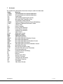
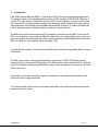
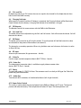
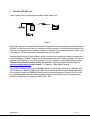
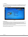
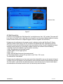
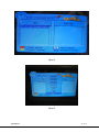
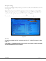
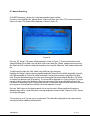
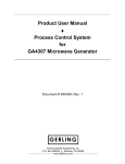
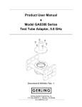
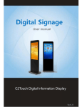
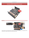
1
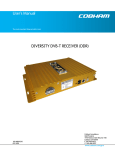
User’s Manual The most important thing we build is trust. DVB-T MONITOR RECEIVER (DMR) 100-M0064X6 05/18/09 Cobham Surveillance GMS Products 1916 Palomar Oaks Way Ste 100 Carlsbad, CA 92008 T: 760-496-0055 F: 760-496-0057 www.cobham.com/gms TABLE OF CONTENTS 1 2 3 4 5 6 7 8 ACRONYMS .................................................................................................................................................................. 3 INTRODUCTION ....................................................................................................................................................... 4 REMOTE CONTROL.................................................................................................................................................. 5 HARDWARE OVERVIEW ...................................................................................................................................... 7 4.1 Speaker......................................................................................................................................................................... 9 4.2 Menu/Select .............................................................................................................................................................. 9 4.3 CH+ and CH- ........................................................................................................................................................... 10 4.4 Charging Indicator............................................................................................................................................... 10 4.5 IR Detector .............................................................................................................................................................. 10 4.6 Vol+ and Vol-.......................................................................................................................................................... 10 4.7 OK/Power ................................................................................................................................................................. 10 4.8 RF input ..................................................................................................................................................................... 10 4.9 Video In .................................................................................................................................................................... 10 4.10 Video Out ................................................................................................................................................................. 10 4.11 Power ......................................................................................................................................................................... 10 4.12 Audio Out .................................................................................................................................................................... 10 4.13 Power Select Switch ........................................................................................................................................... 10 USE WITH GMS MDL LINK ............................................................................................................................ 11 OPERATION .............................................................................................................................................................. 12 6.1 Channel List ..................................................................................................................................................................... 12 6.2 Edit Channel List ............................................................................................................................................................ 13 6.3 Program Guide................................................................................................................................................................ 15 6.4 System Setting ............................................................................................................................................................... 16 6.5 Utility .................................................................................................................................................................................. 16 6.6 Automatic Searching................................................................................................................................................... 17 6.7 Manual Searching ......................................................................................................................................................... 19 M.MENU....................................................................................................................................................................... 20 SPECIFICATIONS ................................................................................................................................................. 22 100-M0064X6 2 of 23 www.cobham.com/gms 1 Acronyms This section lists and describes the various acronyms used in this document. Name Meaning 16 QAM 16-state Quadrature Amplitude Modulation 64 QAM 64-state Quadrature Amplitude Modulation A/V Audio/Video AES Advanced Encryption System (32 bit) ABS Messenger Basic Scrambling (8 bit) ASI Asynchronous Serial Interface COFDM Coded Orthogonal Frequency Division Multiplexing CVBS/Y Composite video/Luminance with S-video C Chroma video D/C Down-Converter DDR Diversity DVB-T Receiver FEC Forward Error Correction GUI Graphical User Interface I/O Input/ Output Kbaud Kilobaud per second Kbps Kilobits per second Mbps Megabits per second MDL Messenger Digital Link MDL-B Messenger Digital Link, Broadcast Version MDR Messenger Digital Receiver MDR-B Messenger Digital Receiver, Broadcast Version MDT Messenger Digital Transmitter MDT-B Messenger Digital Transmitter, Broadcast Version MER Modulation Error Rate MPEG Moving Picture Experts Group NTSC National Television System Committee PAL Phase Alternation Line QPSK Quadrature Phase Shift Keying RF Radio Frequency RX Receiver S/N Signal-to-Noise Ratio TFT Thin Film Transistor THD Total Harmonic Distortion SDI Serial Digital Interface TX Transmitter VDC Volts (Direct Current) 100-M0064X6 3 of 23 www.cobham.com/gms 2 Introduction GMS’ DVB-T Monitor Receiver (DMR) is a state-of-the-art DTV receiver for mobile/portable applications. This compact, battery or DC operated product contains a DVB-T compliant VHF/UHF DVB-T Receiver, 7inch flat TFT screen monitor, a block down converter (BDC) and dual speakers. An analog audio & video jack is provided for viewing on another monitor or for recording purposes. Additionally, external audio & video information can be brought into the DMR and presented on its display. This allows the DMR to be used for monitoring external recorder playback or output of navigation devices. The DMR can be used for direct commercial DTV reception in countries that use DVB-T transmission if a BDC is not installed or it can be used with GMS’ Messenger Series transmitters and for point to point and point to multi-point terrestrial applications. When used in conjunction with GMS’ Block Down Converters (BDCs), the DMR can cover frequency bands exceeding 7 GHz. A typical MDL link includes a Transmitter and the DMR (which includes one integral Block Down Converter and antenna). This MDL system utilizes a robust digital modulation system known as DVB-T COFDM that provides frequency diversity and powerful FEC algorithms. This MDL provides a robust wireless link that is effective against the multipath interference experienced by analog systems and provides a clear picture in the most difficult of terrains. Channel data such as channel number, frequency, bandwidth, and other pertinent information can be stored and saved in a program data file. This manual provides information on how to operate the DMR as well as pertinent technical information related to the overall system. 100-M0064X6 4 of 23 www.cobham.com/gms 3 Remote Control The remote control allows the user to remotely setup and program the DMR (see Figure 1). Table 1 defines the buttons and function. Figure 1 100-M0064X6 5 of 23 www.cobham.com/gms KEYS Power Mute TV/R LAST TV/AV/DVB SYS AUDIO EPG INFO DVB.MENU TEXT EXIT PAUSE LANG M.MENU LCD CCFL 4:3/16:9 OK <0>-<9> REMOTE CONTROL KEYS FUNCTION Switch Off Turn On/Off volume Select TV or Radio mode Return to previous channel Select TV,Audio Video, or DVB mode Select NTSC,PAL or Auto (Auto detect PAL or NTSC) Select Stereo or Mono Display current program information Show channel information Enter DVB-T Menu View Teletext Exit DVB-T Menu N/A Enter program language menu Enter Picture, System Menu Disables the LCD display (Toggle on/off) Backlight brightness select Display aspect ratio of LCD display (4:3 or 16:9) Confirm (Enter) Numeric keys used to input desired frequency or to choose channels Table 1 100-M0064X6 6 of 23 www.cobham.com/gms 4 Hardware Overview 1 2 3 4 5 6 7 8 9 1 Figure 2 Front View (Ref. Table 2) 1 2 3 4 5 6 7 8 9 Speaker Menu/Select CHCH+ Charging Indicator IR Detector for Remote Control VolVol+ OK/Power Hold key depressed for 1 second to turn off power Table 2 100-M0064X6 7 of 23 www.cobham.com/gms 1 2 Figure 3 Rear View (Ref. Table 3 100-M0064X6 8 of 23 www.cobham.com/gms 3 5 4 6 7 Figure 4 Left Side Rear View (Ref. Table 3) 1 Battery support – (Option IDX or Anton Bauer) 2 RF Input (Antenna input) – ‘N’ - Female 3 Video Input (Composite) - BNC - Female Power select switch – (Battery or DC input) Forward position for battery 4 operation, Center position is off, Back position for DC input 5 Video Out (Composite) – BNC - Female 6 DC input, 4 pin XLR, External power – Pin 1 Ground, Pin 4 (9-15 VDC) 7 Audio out (Left/Right) – RCA - Female Table 3 4.1 Speaker The DMR is equipped with two built in audio speakers. 4.2 Menu/Select When the Menu key is depressed, the main Menu will be displayed on the screen. The cursor stops at the first item waiting for user input (selection). 100-M0064X6 9 of 23 www.cobham.com/gms 4.3 CH+ and CHBy depressing the CH+ or CH- buttons the user can step thru the channel list if multiple channels have been saved in the DMR’s memory. 4.4 Charging Indicator When power is turned off and the AC Adaptor is connected, the Charging Indicator will be illuminated. Green indicates that the battery is charging, Red indicates that the battery is charged. 4.5 IR Detector The Remote Control Unit communicates with the DMR via the IR detector. 4.6 Vol+ and VolThe Audio volume can be adjusted using the Vol+ and Vol- buttons. Vol+ will increase the volume. Vol- will decrease the volume. 4.7 OK/Power The power can be turned on or off using this button. To turn the power off, hold the button for at least one second then the power will be removed (see section 6). This button has a secondary operation. When using the Main menu and sub-menus this button is used as an Enter (OK) key. 4.8 RF input Antenna input connection (N type connector – female). 4.9 Video In Used to accept standard composite video in (BNC 75 Ohms - female) 4.10 Video Out The video output (composite video) is available to supply video to remote video devices (BNC 75 Ohms – female). 4.11 Power The input will accept 9 –15VDC 18 Watts. The connector used is a male 4 pin XLR type. See Table 3 for power and ground connections. 4.12 Audio Out Two channels (RCA connector) of unbalanced audio out (Left & right channels). 4.13 Power Select Switch This switch is used to select the source of power for the DMR unit (Battery or DC input). The forward position will select the battery. The back position will select DC Input. The center position is off. 100-M0064X6 10 of 23 www.cobham.com/gms 5 Use With GMS MDL Link Figure 5 shows a basic configuration to establish a MDL wireless link. M DT P o w e r S u p p ly DM R V id e o S o u r c e Figure 5 Most DVB-T receivers are capable of receiving direct frequencies in the range of approximately 49 MHz to 862 MHz. If the transmitter is not in this range then a down-converter is used to convert the frequency to this range. The frequency out of the down-converter is called the IF (intermediate frequency) which is fed to the receiver. The down converter is mounted on the rear of the DMR. Down-converters have a LO (local oscillator) which is mixed with the transmitter frequency and converts it to the IF frequency. The DVB-T receiver must be programmed with the IF frequency directly. The user can calculate the IF frequency (“Transmitter frequency - LO = IF frequency”) to be entered into the receiver. The down-converter LO must be known. (For GMS BDCs, refer to the table on the GMS web site http://www.cobham.com/gms under “Products”, “RF Modules”, “Block Down Converter”). For example, if the transmitter is set for 5800MHz and the LO of the down-converter is 5100 MHz, then the IF frequency is 700 MHz (5800-5100 = 700). The receiver will need to be set to 700 MHz to receive the transmitter frequency of 5800 MHz. Each time the transmitter frequency is changed, the IF must be re-calculated and entered into the receiver. Note that negative or positive numbers are possible when calculating the frequency. For example, 5000-5100 = -100. 100-M0064X6 11 of 23 www.cobham.com/gms 6 Operation Press the “OK/POWER” key on the panel to switch on the power. Press the MENU key. The first item on the screen, Channel List, is highlighted, as shown in Figure 6. By using the Up/Down arrow keys, the user can scroll thru the menu items. To select an item from the menu, press “OK”. The “Exit” key on the remote control will turn off the Menu screen. Figure 6 6.1 Channel List Use the cursor to highlight the “Channel List” on the Main menu. Press “OK” to select. The screen will show a list of stored programs as shown in Figure 7. In this example, only one program is stored. If the transmitter were powered on and operating, there would be a video/picture on the screen area. Press the Menu or Exit (on remote control) button to exit this screen. Depress the red button on the remote control to toggle between all files or favorites files to be displayed. Depress the yellow button on the remote control to select the file sorting method and allows selected files to be locked (cannot be modified or renamed). 100-M0064X6 12 of 23 www.cobham.com/gms Screen Area Figure 7 6.2 Edit Channel List Use the cursor to highlight the “Edit Channel List” on the Main menu. Press “OK” to select. The screen will be as shown in Figure 8. In this mode, files in the channel list can be renamed ,deleted, added as favorites, locked, moved to channel list or skipped (Flagged as file to be skipped in the channel list). By depressing the red button on the remote control, a selection can be made (See Figure 9). Once a selection has been made, depress the “OK” to perform the selected operation. Upon exiting the “Edit Channel List” menu the user will be asked to save or exit (without saving). If saved is selected the chosen operation will be executed. As an example, to delete a file from the channel list do the following: 1.) Highlight the file to be deleted using the up/down arrow keys. 2.) Press the red button on the remote control 3.) Select “delete” from the pop up menu 4.) Press “OK” 5.) Press the DVB. Menu button on the remote control 6.) The monitor display a message “Do you want to save?” Press “OK” to save. The selected file is now deleted. By depressing the yellow button on the remote control the selected file name can be renamed. A keypad as shown in Figure 10 will appear. Use the arrow keys on the remote control to choose desired characters. The “OK” button is used to enter the selected characters. Once the new name has been entered, depress the red button on the remote control to save. Use the exit key to exit the menu. 100-M0064X6 13 of 23 www.cobham.com/gms Figure 8 Figure 9 100-M0064X6 14 of 23 www.cobham.com/gms Figure 10 6.3 Program Guide The program guide will display the selected channel video and contents as shown in Figure 11.Press the “OK” button to show program information. Press the red button to change the channel list. Press the blue button to change the current or next program information. The weekly program guide applies only to commercial DTV applications. Figure 11 100-M0064X6 15 of 23 www.cobham.com/gms 6.4 System Setting Use the cursor to highlight the “System Setting” on the Main menu. Press “OK” to select. The screen will as shown Figure 12. System setting allows the user to select key operating parameters such as language, screen type (4:3, 16:9), time settings, factory default reset, and display system information. Select from the “Setup List” using the up/down arrow keys then press the “OK” button. The available settings are selected from the screen shown on the right. After a selection has been made, press the “OK” button. Parental lock, receiver lock, and banner time are used in the DTV commercial application. Figure 12 6.5 Utility Use the cursor to highlight the “Utility” on the Main menu. Press “OK” to select. The screen will as shown Figure 13. Utility provides an animated demonstration on how to use the system, a means of changing the calendar, and games are provided for the user’s amusement. 100-M0064X6 16 of 23 www.cobham.com/gms Figure 13 6.6 Automatic Searching Use the cursor to highlight the “Automatic Search” field on the Main menu. Press “OK” button. The screen will be displayed as shown in Figure 14. Select desired region (China for 8 MHz bandwidth, Australia for 7 MHz bandwidth or Taiwan for 6 MHz bandwidth).Select “Fast” or “Slow” search speed. Press the “OK” button. The screen as shown in Figure 15 will be displayed. If a channel is detected during this operation, it will be stored in the “Channel list” memory. Up to 1000 programs can be stored. Press the Menu or Exit button (on remote control) to exit this screen. 100-M0064X6 17 of 23 www.cobham.com/gms Figure 14 Figure 15 100-M0064X6 18 of 23 www.cobham.com/gms 6.7 Manual Searching If the RF/IF frequency is known this is the recommended search method. Use the cursor to highlight the “Manual Search” field on the Main menu. Press “OK” to enter the Manual Search sub-menu. The screen will be displayed as shown in Figure 16. Figure 16 Press the “OK” button. The screen will be displayed as shown in Figure 17. One of three modes can be selected (Delete, Edit, or Add) using the left or right arrow. Select the “Delete” mode to erase an existing file. Select the “Edit” mode to change the frequency an existing file. Select the “Add” mode to add a new file. To add a new file, select the “Add” mode using the left or right arrow keys. Highlight the “Region” field to select the desired bandwidth. Select China for 8 MHz bandwidth, Australia for 7 MHz bandwidth or Taiwan for 6 MHz bandwidth. Use the down arrow key to highlight the “MHz” field. Enter the desired frequency using the numeric keypad of the remote control then press “OK”(Refer to section 5 to determine the IF frequency). The screen will be displayed as in Figure 16 again. The signal strength (red bar) and quality (blue bar) indicator at the bottom of the screen should be present if the transmitter is outputting a signal. If the quality indicator is not present then the signal from the transmitter may require an inverted spectrum (See the transmitter operators’ manual). Press the “Red” button on the remote control unit to start the search. When the desired frequency is detected, there will be a short delay with a message displayed “search finished”. Depress the “Exit” button. A message will appear “Do you want to save?” Answer yes to save the data. The video will be displayed on the screen and the new channel will be added to the channel list. 100-M0064X6 19 of 23 www.cobham.com/gms Figure 17 7 M.Menu Pressing the “M.Menu” key on the remote control enters the “Pictures/System” menu. This mode allows the user to adjust settings such as brightness, contrast, color, sharpness, and hue (Picture menu). Use the left/right arrows to change the settings. By pressing the M.Menu key a second time, other settings such as language type, input type (DVB or Video), Pic Mod (Screen orientation), and Color Sys (Auto,NTSC,PAL,or SECAM) can be programmed. If Video is selected as the “input type”, composite video from another source will be displayed on the monitors screen. Figure 18 shows the picture screen. Figure 19 shows the system screen. 100-M0064X6 20 of 23 www.cobham.com/gms Figure 18 Figure 19 Note: When the DMR is used as a receiver, the “Input” field must be set to “DVB”. If “Video” is selected, the DMR will accept audio/video from another source at the AV Inputs. 100-M0064X6 21 of 23 www.cobham.com/gms 8 Specifications RF & DVB-T COFDM CHARACTERISTICS: Nordig II and ETS 300 744 DVB-T full compliance 174 MHz to 862 MHz frequency range for VHF and UHF. Optional BDCs provide reception to 6 GHz inbands. Manual Tuning Resolution: 1 MHz Auto-Search for Commercial Channels OFDM demodulation 2 K and 8K FFT for SFN and MFN Symbol rates up to 60MBPs Automatic adjacent-channel interference cancellation Supports QPSK and 16/64 QAM constellations Supports ¼, 1/8, 1/16, 1/32 guard interval Supports FEC decoding: ½, 2/3, ¾ 5/6 and 7/8 Supports reed-solomon (204,188) ETS 300 477 DVB/MPEG2 transport and de-multiplexing: ISO/IEC 13818-1 MPEG-2 transport stream compliance Video decoding and OSD: ISO/IEC 13818-2 MPEG-2 video MP at ML compliance ISO/IEC 11172-2 MPEG-1 video compliance Resolution: 720 x 480 for NTSC and 720 x 576 for PAL 16:9/4:3, letterbox and pan/scan Audio decoding: ISO/IEC 13818-3 MPEG-2 audio compliance Single/stereo Sampling rate up to 48kHz Supports linear PCM sample rates up to 96kHz Front Panel: Power-on LED Menu select Channel select (CH-, CH+) Charge indicator IR detector for remote control Audio volume control (Vol-,Vol+) Power on switch Left Side Panel: Video in, BNC female connector Video out, BNC female connector Audio output, RCA male connectors (Two channels – Unbalanced output) DC power in, 7-15 VDC, XLR connector 100-M0064X6 22 of 23 www.cobham.com/gms Mechanical properties: Dimensions (WxDxH) w/o battery: 12.3in X 6.5in X 3.58in/ 314mm x 165.7mm x 91.3mm Weight: 4.6 lbs/2.086 Kg Operation temperature: +1 to +40 degrees Celsius Storage temperature: -0 to +80 degrees Celsius 100-M0064X6 23 of 23 www.cobham.com/gms