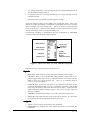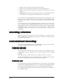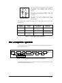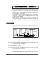
1
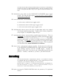
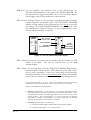
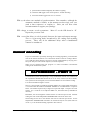
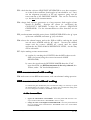
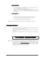
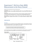
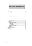
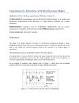
CONVOLUTIONAL CODING
PREPARATION................................................................................. 78
convolutional encoding ............................................................. 78
encoding schemes...................................................................... 80
convolutional decoding ............................................................. 80
TIMS320 DSP-DB...................................................................................80
TIMS320 AIB ..........................................................................................80
the complete system .................................................................. 81
EXPERIMENT - PART A.................................................................. 82
encoding .................................................................................... 82
decoding .................................................................................... 83
manual encoding ....................................................................... 85
EXPERIMENT - PART B.................................................................. 85
BER measurement with coding ................................................................87
BER measurement without coding ...........................................................87
interpretation ............................................................................. 88
TUTORIAL QUESTIONS ................................................................. 88
Convolutional coding
Vol D2, ch 9, rev 1.0
- 77
CONVOLUTIONAL CODING
ACHIEVEMENTS: setting up and testing of a convolutional encoder and decoder
pair. Inclusion into a noisy, bandlimited communication system;
observation and measurement of changes to BER.
PREREQUISITES: completion of the experiment entitled BER measurement in
the noisy channel in this Volume.
ADVANCED MODULES: CONVOLUT`L ENCODER, TIMS320 DSP-DB (with
decoding EPROMS), and TIMS320 AIB; plus all those modules
required for the pre-requisite experiment, namely LINE-CODE
ENCODER, LINE-CODE DECODER, DECISION MAKER, ERROR
COUNTING UTILITIES, WIDEBAND TRUE RMS METER, an extra
SEQUENCE GENERATOR, BASEBAND CHANNEL FILTERS,
NOISE GENERATOR. TRUNKS are optional
PREPARATION
The experiment is divided into two parts - A and B.
Part A introduces the CONVOLUT`L ENCODER module, and a pair of modules
which together perform the decoding. These modules are examined in relative
isolation.
Part B places them into a communications system, where their contribution is to
reduce the errors introduced by the noisy, bandlimited channel.
convolutional encoding
It is assumed you have had some introduction to the concept of coding in general,
and of convolutional coding in particular. Suffice to say that for this experiment
there is no need to know any of the theory which gave rise to this coding scheme,
although it would, of course, add to your appreciation of the experiment.
The aim of the experiment is to show that:
• the form of convolutional encoding implemented is such that extra bits are added
to a serial input message (data) stream
• after encoding the output bit rate is twice that of the input bit rate
78 - D2
Convolutional coding
• it is not easy (impossible?), by observing the input and output simultaneously, to
describe what the coding scheme is
• an algorithm exists for recovering (deciphering) the original message from the
encoded bit stream
• there are benefits to be gained by performing this encoding !
As in other forms of coding, bits are added to the original data stream. Thus, if the
channel over which the message is transmitted is band limited, then the bit rate must
remain as before, and so the message rate - the rate at which the wanted message
arrives at the far end - will be slowed. But the error rate will be reduced. Overall
there is an advantage in this. See Tutorial Question Q1.
Convolutional encoding is implemented with the CONVOLUT`L ENCODER
module, the front panel of which is depicted below.
MODE SELECT
4-LEVEL OUT
CODE SELECT
PARALLEL
TTL OUT
ext BIT CLK SYNC
SERIAL IN
MASTER CLK
2-LEVEL
SERIAL OUT
BIT CLK
SAMPLING CLOCK
Figure 1: the CONVOLUT`L ENCODER front panel
Descriptions of the various front panel connections are:
inputs
• mode select: three modes (see panel) selected by the three-position toggle
• code select: there are two convolutional coding schemes, selected with a twoposition toggle switch. Each is rate ½, which means there are as many code bits
added as there are original message bits. CODE 1 is of constraint length 3;
CODE 2 is of constraint length 4.
• ext bit clk sync: for the case that there are two modules being driven by the
8.333 kHz MASTER CLOCK (as in this experiment), and where each divides
this by four, the resulting 2.083 kHz need to be kept in phase. A patch from the
LINE-CODE ENCODER 2.083 kHz output to this ‘ext bit clk sync’ input will
force this condition.
• serial data: the input data (message) to be coded - from the message source.
• master clk: from which all other clocks are derived by division. It is four times
the output bit rate (and so eight times the message bit rate).
outputs
• 4-level: a 4-level output; not involved in this experiment
• parallel TTL: two adjacent bits of the output bit stream; not involved in this
experiment.
Convolutional coding
D2
- 79
• 2-level: a bi-level (‘analog’) version of the serial output
• serial: TTL level encoded version of the serial data (message) input.
• bit clk: in phase with the serial output. Becomes the ‘stolen bit clock’ for the
receiver.
• sampling clock: half the rate of the output bit clock; correctly phased to drive
the message source (a SEQUENCE GENERATOR in this experiment).
The CONVOLUT`L ENCODER module accepts serial data (the message) as input.
Its output may be in serial form, but is also available in parallel format (which
includes a 4-level signal). Only the serial format will be considered in this
experiment.
The common bit rate for most of TIMS experiments is 2.083 kHz, and a clock at this
rate is available from the MASTER SIGNALS module. But if this is to be the
transmitted bit rate, then a clock at half this rate is required to run the SEQUENCE
GENERATOR which will be used to represent the message. Such a clock
(1.042 kHz), called the sampling clock, is provided by the CONVOLUT`L
ENCODER.
encoding schemes
Reference should now be made to the Advanced Modules User Manual for more
detail regarding the coding schemes, test patterns, bit formats, and other technical
details (including references).
convolutional decoding
The decoder is implemented with a pair of TIMS digital signal processing modules,
namely the TIMS320 DSP-DB and the TIMS320 AIB.
TIMS320 DSP-DB
This development board (‘DB’) module must be fitted with two EPROMS (erasable
programmable read only memory) which contain software for the decoding
algorithm.
Check that the four on-board MEMORY SELECT jumpers are in the ‘A’ position.
The decoding algorithm can also be obtained from a PC connected to the front panel
but this option will not be invoked for this experiment.
SERIAL LINK,
TIMS320 AIB
This analog interface board (‘AIB’) module serves as the interface to the decoding
software of the TIMS320 DSP-DB. For this it is essential that the TIMS320 AIB be
inserted into the TIMS frame immediately to the right of the TIMS320 DSP-DB.
It is a general purpose module, and the front panel connections are re-defined for
each EPROM installed.
80 - D2
Convolutional coding
Only four of the front panel connections are required
for operation of the TIMS320 AIB module in
convolutional code decoding mode, as shown
opposite.
CLK
CODE
The input CLK is that associated with the
convolutionally encoded CODE input. This is at
2.083 kHz.
CLK
DATA
The output CLK is at the message (DATA) rate of
1.042 kHz.
It will be used for the BER
instrumentation.
AIB front panel
The function of the three-position toggle switch is described in Table 1 below, and
explained later.
toggle
POSITION
Decoder
mode
AUTOMATIC
operation
MANUAL
operation
UPPER
automatic
not used
MIDDLE
manual
requires test code
as input
decodes as ‘normal’
LOWER
manual (reverse
of middle)
decodes as ‘reverse’
initially branch bit
randomly selected
branch bits reversed
Table 1: AIB Toggle Switch function
the complete system
A block diagram of the system to be studied, but without BER instrumentation, is
shown in Figure 2 below.
PRBS
(message
source)
CONV'L
ENCODE
LINE
CODE
NOISY
BANDLIMITED
CHANNEL
DETECTOR
LINE
DECODE
CONV'L
DECODE
DATA OUT
DATA CLOCK
2.083 kHz sync
1.042 kHz
stolen clock
MASTER 8.333 kHz CLOCK
Figure 2: block diagram of the system to be modelled
In particular this shows the sources of each of the clocks, all derived from the TIMS
8.333 kHz MASTER SIGNALS clock.
Convolutional coding
D2
- 81
EXPERIMENT - PART A
In Part B of this experiment the encoder and decoder of Part A will become part of a
transmission system operating from the 8.333 kHz clock of the MASTER SIGNALS
module.
Part of this system is a LINE-CODE ENCODER module, which produces a clock at
one quarter of this rate, namely 2.083 kHz.
The convolutional encoding scheme to be implemented requires input data at half
this rate again; so it in turn produces a 1.042 kHz clock for the message, provided
by a SEQUENCE GENERATOR.
Detailed information about the three new modules to be examined - the
CONVOLUT`L ENCODER, the TIMS320 AIB, and the TIMS320 DSP-DB - may
be found in the Advanced Modules User Manual. However, it is not necessary to
refer to this for the purposes of the experiment. There are several on-board settings
to be made, but it is assumed this will have been done by your Laboratory Manager.
encoding
A model of the encoding part of the block diagram of Figure 2 is shown in Figure 3
below.
serial data OUT
line coding not
implemented
8333 1042
2083
bit clock
2083
Figure 3: model of the encoding section of Figure 1
To set this model up the following steps are recommended.
T1 set the SEQUENCE GENERATOR for a short sequence (both toggles of the
on-board switch SW2 should be UP).
T2 patch up as shown in Figure 3.
T3 check that the clock and synchronization signals are present, and on the
frequencies indicated in Figure 3.
The LINE-CODE ENCODER is being used although for the present no line coding
is being implemented. There is no need, then, to press its RESET button.
82 - D2
Convolutional coding
Note that both the LINE-CODE ENCODER and the CONVOLUT`L ENCODER are
clocked by the same 8.333 kHz MASTER SIGNAL, which they immediately divideby-four. To keep their dividers in step, a sync. signal is sent from the former to the
latter.
T4 momentarily press RESET on the CONVOLUT`L ENCODER (upper toggle
switch). This must be done again, if ever the clock or synch. signal is
broken, then reconnected.
T5 on the CONVOLUT`L ENCODER:
a) select CODE 1 with the lower toggle switch
b) momentarily RESET with the upper toggle switch.
c) select TEST CODE with the upper toggle switch.
T6 simultaneously observe B.CLK (bit clock of coded data) and S.CLK (sample
clock of un-coded message data). Confirm their relative frequencies
(as per Figure 3), and phases (edges line up).
T7 simultaneously observe B.CLK and the encoded output from DATA. This is a
test pattern. It results from sending the encoder (with the upper toggle
switch on TEST CODE) a stream of ones (1, 1, 1, 1, 1....). Depending
upon the code (CODE 1 or CODE 2) so a different pattern emerges from
the encoder. The decoder uses these patterns to recognise the coding
scheme and so obtain bit synchronization (see later). The test patterns
are described in the Advanced Modules User Manual.
T8 select CODE 1, and switch to NORMAL encoding. Synchronize the oscilloscope
to the SEQUENCE GENERATOR SYNC signal, and observe both the
input message sequence and the encoded output. Confirm the
difference in bit rate. Can you see any relationship between the two
patterns ? Unlikely ! But there is, of course; just ask the decoder !
decoding
The convolutional decoder is implemented in software. Two modules are required,
the TIMS320 AIB and the TIMS320 DSP-DB. These should already have been
configured, by your Laboratory Manager, for correct operation.
However there is a jumper, J1, on the DB board (located near the EPROM U5).
This has two positions, ‘L’ and ‘H’. In the ‘L’ position the decoder is set up to
decode CODE 1 of the encoder module (use ‘H’ for CODE 2).
T9 before inserting the TIMS320 DSP-DB check the position of J1 (explained
above).
Convolutional coding
D2
- 83
T10 insert the two modules into adjacent slots of the TIMS frame, the
TIMS320 AIB immediately to the right of the TIMS320 DSP-DB. Set
the PROGRAM/RUN toggle on the DB to RUN. Press the RESET button.
Set the toggle switch on the AIB to the central position.
T11 patch according to Figure 4. The incoming serial data goes direct from the
encoder output to the decoder input. The LINE-CODE ENCODER
module is being used for clock generation, but will not yet be used for
line coding. So a LINE-CODE DECODER is not yet required. Note
also that the noisy channel of Figure 1 is not yet implemented. So no
detector (decision maker) is required.
interconnection
via back plane
bit CLK (2.083)
serial IN
(encoded data)
(1.042)
data CLK
serial OUT
(decoded data)
Figure 4: the convolutional decoder model.
T12 confirm the presence of a data clock (1.042 kHz) from the decoder (#1 TTL
output of the AIB). This will be required later for the BER
instrumentation.
T13 compare the message data, from the SEQUENCE GENERATOR, and the
decoded output from the decoder (TTL output #2 of the AIB). There
may or not be agreement. In any case, when using the oscilloscope,
remember that there will be a considerable delay (many clock periods)
between the two sequences, due to the coding and decoding processes.
If the decoded output is in error, then it (the decoder) must be incorrectly
synchronized. Due to the code in use, it can only be one bit out in its timing.
There are two methods of synchronization.
1. manual synchronization: if the decoder is not correctly synchronized to the
clock, this can be corrected by synchronizing to an adjacent clock period. This is
accomplished by moving the AIB toggle switch from CENTRE to LOW (or the
reverse) position. On a real message (or a very long sequence) it would be
impossible to confirm synchronization by merely observing the decoded
message; so this could be a ‘hit and miss’ procedure.
2. automatic synchronization. To initiate this:
a) switch the encoder toggle to TEST mode (sends a known pattern)
b) switch the AIB toggle UP to AUTOMATIC mode
84 - D2
Convolutional coding
c) synchronization acknowledged by the AIB LED lighting
d) switch the AIB toggle to the central position - normal decoding
e) return the encoder toggle from TEST to NORMAL
T14 try the above two methods of synchronization. But remember, although the
automatic method is reliable, at the moment you have only your eyes
(and a short sequence) to confirm it. Soon you will have some
instrumentation to support your findings.
T15 change to CODE 2 at the transmitter. Move J1 on the DB board to ‘H’.
Repeat the previous Task.
T16 record the delay (in clock periods) between the input and output message.
This is a processing delay introduced by the coding and encoding
process. There will be an additional delay when a bandlimited
channel is introduced.
manual encoding
If you are interested in personally checking the encoding algorithm, you should first
refer to the Advanced Modules User Manual for details of the two coding schemes.
You could then check that they have been correctly implemented by carrying out a
bit-by-bit analysis of the encoder outputs (on a short sequence).
When you are satisfied with your progress it is time to introduce convolutional
coding to the transmission system.
EXPERIMENT - PART B
A transmission system incorporating a noisy, bandlimited channel was examined in
the experiment entitled BER measurement in the noisy channel (in this Volume).
This system will be used again, but now with the addition of convolutional coding.
It is shown modelled in Figure 5 below.
Since it is not possible to include all required modules in a single TIMS 301 frame it
is convenient that the NOISY CHANNEL MODEL be accommodated in a separate
frame. The channel requires only a single wire input and output. It requires no clock
signals. So it could be in an adjacent TIMS 301, interconnected by TRUNKS if
necessary.
Remember, the rate through the channel will be at 2.083 bits-per-second. Without
coding the clock of the SEQUENCE GENERATOR will also be at this rate.
With coding the bit rate in the channel will still be 2.083 bits-per-second. So the
SEQUENCE GENERATOR will need to be clocked at half this rate (both codes are
of rate ½), as in the model already prepared in Part A above.
Convolutional coding
D2
- 85
ext trig
Z-MOD
1.042 kHz
re-timed
(2.084 kHz)
TIMS320 DSP-DB not shown !
stolen bit clock
TRANSMITTER
NOISY CHANNEL
RECEIVER
Figure 5: the system with convolutional coding.
For details of the noisy channel model refer to the experiment entitled The noisy
channel model (Volume D1). For details of the BER instrumentation see the
Chapter entitled BER instrumentation macro model (this Volume).
patching
A systematic patching procedure is recommended. At each stage always check that,
after achieving synchronization, the input sequence has been successfully recovered
at the output.
When you are already experienced in patching up these larger systems you may feel
such small steps are unnecessary.
T17 insert just the LINE-CODE ENCODER and LINE-CODE DECODER
modules between the transmitter and receiver. Clock each with the
B.CLK of the CONVOLUT`L ENCODER. Use NRZ-L code.
T18 insert the DECISION MAKER between the LINE-CODE ENCODER and the
LINE-CODE DECODER. Clock the DECISION MAKER with the
B.CLK of the CONVOLUT`L ENCODER.
Clock the LINE-CODE
DECODER with the B.CLK from the DECISION MAKER. Since there is
no bandlimiting the decision point can be set almost anywhere (except
on a transition).
T19 insert channel #3 of a BANDPASS CHANNEL FILTERS module between the
LINE-CODE ENCODER and the DECISION MAKER. Now that
bandlimiting is included, it will be necessary to examine the eye
pattern at the output of the channel, and adjust for the best decision
instant.
T20 place an ADDER at both the input and the output of the channel filter. Use
the ‘G’ inputs, setting both gains near unity.
T21 confirm the message is still being decoded successfully.
T22 add the instrumentation
86 - D2
Convolutional coding
T23 check that the reference SEQUENCE GENERATOR is on a short sequence,
as is that at the transmitter (both toggles of SW2 should be UP). Carry
out the alignment procedure of the two sequences going into the
EXCLUSIVE-OR of the DECISION MAKER. This can be checked by
eye, but also by the instrumentation.
T24 change both sequence generators to a long sequence (both toggles of SW2
should be DOWN). Re-align the system (ie, synchronize the
CONVOLUT`L DECODER, re-align the reference SEQUENCE
GENERATOR). Use the instrumentation to show that there are no
errors.
T25 patch maximum available noise from a NOISE GENERATOR to the ‘g’ input
of the INPUT ADDER, and rotate ‘g’ fully clockwise.
T26 observe the channel output, and set the SNR to 0 dB by reducing the signal
into the INPUT ADDER with the ‘G’ control. Increase the channel
output with the OUTPUT ADDER ‘G’ control until the signal
approaches the TIMS ANALOG REFERENCE LEVEL; but this may
not be achievable.
T27 before making serious measurements:
a) confirm, by watching the COUNTER, that the BER reduces as the
SNR is increased (using the ATTENUATOR on the NOISE
GENERATOR).
b) centre the signal into the DECISION MAKER about the 25 mV
input threshold (see BER measurement in the noisy channel, this
Volume, under ‘DC threshold adjustment’).
BER measurement with coding
T28 make some serious BER measurements, with convolutional coding operative.
BER measurement without coding
To estimate the gain introduced by the convolutional coding it is necessary to repeat
the measurements, but without coding. To remove the convolutional coding there
are seven changes to be made (in Task T29). These will be:
to the transmitter:
1. bypass the CONVOLUT`L ENCODER: move the patch lead from the DATA
output of the CONVOLUT`L ENCODER to the DATA input.
2. change the clock to the SEQUENCE GENERATOR: move the patch lead from
the S.CLK output of the CONVOLUT`L ENCODER to the B.CLK of the LINECODE ENCODER.
Convolutional coding
D2
- 87
to the receiver
3. bypass the CONVOLUT`L DECODER: move the patch lead from the TTL
OUTPUT #2 of the AIB module to the TTL INPUT #1.
4. change the clock to the reference SEQUENCE GENERATOR: move the patch
lead from the TTL OUTPUT #1 of the AIB to the STROBE output of the LINE-CODE
DECODER.
to the system
5. press all re-set buttons (not strictly necessary, but a matter of principle).
6. re-align the reference SEQUENCE GENERATOR (with no noise).
7. re-set the decision instant of the DECISION MAKER.
T29 remove the convolutional coding, and repeat the BER measurements.
interpretation
The procedures outlined above have enabled you to make serious measurements of
BER, with and without convolutional coding.
The two cases had different message rates, although the same bit rate through the
same channel.
Make sure you have enough information to enable an answer to Tutorial Question
Q1.
TUTORIAL QUESTIONS
Q1 convolutional (and other) encoding used over a bandlimited channel results
in a reduced message bit rate, but offers the benefit of less errors.
Taking account of the different message rates, discuss how you might
attempt to estimate the gain obtained with the two convolutional codes
provided by the CONVOLUT`L ENCODER.
88 - D2
Convolutional coding