1
Configuration and User
Guide
victor unified client
victor site manager
Version 4.2
8200-0960-01 A0
Notice
The information in this manual was current when published. The manufacturer reserves the right to revise and improve its
products. All specifications are therefore subject to change without notice.
Copyright
Under copyright laws, the contents of this manual may not be copied, photocopied, reproduced, translated or reduced to
any electronic medium or machine-readable form, in whole or in part, without prior written consent of Tyco International Ltd.
© 2012 and its Respective Companies. All Rights Reserved.
American Dynamics
6600 Congress Avenue
Boca Raton, FL 33487 U.S.A.
Customer Service
Thank you for using American Dynamics products. We support our products through an extensive worldwide network of
dealers. The dealer through whom you originally purchased this product is your point of contact if you need service or
support. Our dealers are empowered to provide the very best in customer service and support. Dealers should contact
American Dynamics at (800) 507-6268 or (561) 912-6259 or on the Web at www.americandynamics.net.
Trademarks
Windows® is a registered trademark of Microsoft Corporation. PS/2® is a registered trademark of International Business
Machines Corporation.
The trademarks, logos, and service marks displayed on this document are registered in the United States [or other
countries]. Any misuse of the trademarks is strictly prohibited and Tyco International Ltd. will aggressively enforce its
intellectual property rights to the fullest extent of the law, including pursuit of criminal prosecution wherever necessary. All
trademarks not owned by Tyco International Ltd. are the property of their respective owners, and are used with permission
or allowed under applicable laws.
Product offerings and specifications are subject to change without notice. Actual products may vary from photos. Not all
products include all features. Availability varies by region; contact your sales representative.
License Information
Your use of this product is governed by certain terms and conditions. Please see the detailed license information at the end
of this manual.
Disclaimers
MPEG-4 Disclaimer:
THIS PRODUCT IS LICENSED UNDER THE MPEG-4 VISUAL PATENT PORTFOLIO LICENSE FOR THE PERSONAL
AND NON-COMMERCIAL USE OF A CONSUMER TO (i) ENCODING VIDEO IN COMPLIANCE WITH THE MPEG-4
VISUAL STANDARD ("MPEG-4 VIDEO") AND/OR (ii) DECODING MPEG-4 VIDEO THAT WAS ENCODED BY A
CONSUMER ENGAGED IN A PERSONAL AND NON-COMMERCIAL ACTIVITY AND/OR WAS OBTAINED FROM A
VIDEO PROVIDER LICENSED BY MPEG LA TO PROVIDE MPEG-4 VIDEO. NO LICENSE IS GRANTED OR SHALL BE
IMPLIED FOR ANY OTHER USE. ADDITIONAL INFORMATION INCLUDING THAT RELATING TO PROMOTIONAL,
INTERNAL AND COMMERCIAL USES AND LICENSING MAY BE OBTAINED FROM MPEG LA, LLC. SEE
HTTP://WWW.MPEGLA.COM
H.264 Disclaimer:
THIS PRODUCT IS LICENSED UNDER THE AVC PATENT PORTFOLIO LICENSE FOR THE PERSONAL AND NONCOMMERCIAL USE OF A CONSUMER TO (i) ENCODE VIDEO IN COMPLIANCE WITH THE AVC STANDARD ("AVC
VIDEO") AND/OR (ii) DECODE AVC VIDEO THAT WAS ENCODED BY A CONSUMER ENGAGED IN A PERSONAL AND
NON-COMMERCIAL ACTIVITY AND/OR WAS OBTAINED FROM A VIDEO PROVIDER LICENSED TO PROVIDE AVC
VIDEO. NO LICENSE IS GRANTED OR SHALL BE IMPLIED FOR ANY OTHER USE. ADDITIONAL INFORMATION MAY
BE OBTAINED FROM MPEG LA, L.L.C. SEE HTTP://WWW.MPEGLA.COM
ii
Configuration and User Guide
Table of Contents
Overview of victor Unified Video Management Solution
1
Introduction . . . . . . . . . . . . . . . . . . . . . . . . . . . . . . . . . . . . . . . . . . . . . . . . . . . . . . . 1-1
victor unified client . . . . . . . . . . . . . . . . . . . . . . . . . . . . . . . . . . . . . . . . . . . . . . . . . . 1-1
victor site manager. . . . . . . . . . . . . . . . . . . . . . . . . . . . . . . . . . . . . . . . . . . . . . . . . . 1-2
victor player . . . . . . . . . . . . . . . . . . . . . . . . . . . . . . . . . . . . . . . . . . . . . . . . . . . . . . . 1-3
victor Command Center . . . . . . . . . . . . . . . . . . . . . . . . . . . . . . . . . . . . . . . . . . . . . . 1-3
victor/C·Cure Integration . . . . . . . . . . . . . . . . . . . . . . . . . . . . . . . . . . . . . . . . . . . . . 1-4
C·Cure 9000. . . . . . . . . . . . . . . . . . . . . . . . . . . . . . . . . . . . . . . . . . . . . . . . . . . . . . . 1-4
Installation
2
Introduction . . . . . . . . . . . . . . . . . . . . . . . . . . . . . . . . . . . . . . . . . . . . . . . . . . . . . . . 2-1
General . . . . . . . . . . . . . . . . . . . . . . . . . . . . . . . . . . . . . . . . . . . . . . . . . . . . . . . . . . 2-1
Change Windows Local Security Policy (Win 7) . . . . . . . . . . . . . . . . . . . . . . . . . . . 2-3
Installing .NET . . . . . . . . . . . . . . . . . . . . . . . . . . . . . . . . . . . . . . . . . . . . . . . . . . . . . 2-3
Installation disc. . . . . . . . . . . . . . . . . . . . . . . . . . . . . . . . . . . . . . . . . . . . . . . . . . . . . 2-4
Installing victor site manager . . . . . . . . . . . . . . . . . . . . . . . . . . . . . . . . . . . . . . . . . . 2-5
victor site manager prerequisites. . . . . . . . . . . . . . . . . . . . . . . . . . . . . . . . . . . . . 2-6
Installing victor unified client Software . . . . . . . . . . . . . . . . . . . . . . . . . . . . . . . . . . 2-10
victor client Prerequisites: . . . . . . . . . . . . . . . . . . . . . . . . . . . . . . . . . . . . . . . . . 2-10
Adding CCure Integration to standalone victor Installation (Win7). . . . . . . . . . . . . 2-14
Adding a new Windows user account (Win 7) . . . . . . . . . . . . . . . . . . . . . . . . . . . . 2-16
Apply for victor License . . . . . . . . . . . . . . . . . . . . . . . . . . . . . . . . . . . . . . . . . . . . . 2-17
Activate victor License . . . . . . . . . . . . . . . . . . . . . . . . . . . . . . . . . . . . . . . . . . . . . . 2-19
Getting Started
3
Introduction . . . . . . . . . . . . . . . . . . . . . . . . . . . . . . . . . . . . . . . . . . . . . . . . . . . . . . . 3-1
Starting site manager Services . . . . . . . . . . . . . . . . . . . . . . . . . . . . . . . . . . . . . . . . 3-1
Services. . . . . . . . . . . . . . . . . . . . . . . . . . . . . . . . . . . . . . . . . . . . . . . . . . . . . . . . 3-1
Server Components . . . . . . . . . . . . . . . . . . . . . . . . . . . . . . . . . . . . . . . . . . . . . . 3-3
Starting the client . . . . . . . . . . . . . . . . . . . . . . . . . . . . . . . . . . . . . . . . . . . . . . . . . . . 3-3
Exploring the Default Workspace. . . . . . . . . . . . . . . . . . . . . . . . . . . . . . . . . . . . . . .
Home Tab - User control buttons including: . . . . . . . . . . . . . . . . . . . . . . . . . . . .
Build Tab - Tools Include: . . . . . . . . . . . . . . . . . . . . . . . . . . . . . . . . . . . . . . . . . .
Setup Tab - System Configuration tools including: . . . . . . . . . . . . . . . . . . . . . . .
3-5
3-5
3-6
3-7
iii
Table of Contents
Status Bar - Displays system information including: . . . . . . . . . . . . . . . . . . . . . . 3-8
Device List - Configure devices including:. . . . . . . . . . . . . . . . . . . . . . . . . . . . . . 3-8
Save and Close options . . . . . . . . . . . . . . . . . . . . . . . . . . . . . . . . . . . . . . . . . . . 3-9
Switch Language/Culture . . . . . . . . . . . . . . . . . . . . . . . . . . . . . . . . . . . . . . . . . . . . . 3-9
Reposition the Quick Access Toolbar . . . . . . . . . . . . . . . . . . . . . . . . . . . . . . . . . . 3-10
Log Out/Switch Operator . . . . . . . . . . . . . . . . . . . . . . . . . . . . . . . . . . . . . . . . . . . . 3-10
Recorders
4
Introduction . . . . . . . . . . . . . . . . . . . . . . . . . . . . . . . . . . . . . . . . . . . . . . . . . . . . . . . 4-1
Add a New Recorder to a LAN. . . . . . . . . . . . . . . . . . . . . . . . . . . . . . . . . . . . . . . . . 4-2
Add a New Recorder to a WAN . . . . . . . . . . . . . . . . . . . . . . . . . . . . . . . . . . . . . . . . 4-3
Add Multiple Recorders . . . . . . . . . . . . . . . . . . . . . . . . . . . . . . . . . . . . . . . . . . . . . . 4-4
Edit a Recorder . . . . . . . . . . . . . . . . . . . . . . . . . . . . . . . . . . . . . . . . . . . . . . . . . . . . 4-5
Configure VideoEdge NVR (4.2+) . . . . . . . . . . . . . . . . . . . . . . . . . . . . . . . . . . . . . . 4-7
Change Bandwidth Configuration settings . . . . . . . . . . . . . . . . . . . . . . . . . . . . . . . . 4-8
Virtual Private Network (VPN) . . . . . . . . . . . . . . . . . . . . . . . . . . . . . . . . . . . . . . . . . 4-9
Displaying Recorders . . . . . . . . . . . . . . . . . . . . . . . . . . . . . . . . . . . . . . . . . . . . . . . . 4-9
Delete a Recorder . . . . . . . . . . . . . . . . . . . . . . . . . . . . . . . . . . . . . . . . . . . . . . . . . 4-10
View all Cameras on a Recorder . . . . . . . . . . . . . . . . . . . . . . . . . . . . . . . . . . . . . . 4-10
Refresh all Recorders . . . . . . . . . . . . . . . . . . . . . . . . . . . . . . . . . . . . . . . . . . . . . . 4-11
Refresh Individual Recorders. . . . . . . . . . . . . . . . . . . . . . . . . . . . . . . . . . . . . . . . . 4-11
Cameras
5
Introduction . . . . . . . . . . . . . . . . . . . . . . . . . . . . . . . . . . . . . . . . . . . . . . . . . . . . . . . 5-1
Show all Cameras . . . . . . . . . . . . . . . . . . . . . . . . . . . . . . . . . . . . . . . . . . . . . . . . . . 5-1
Show all Online Cameras. . . . . . . . . . . . . . . . . . . . . . . . . . . . . . . . . . . . . . . . . . . . . 5-1
Show all Offline Cameras. . . . . . . . . . . . . . . . . . . . . . . . . . . . . . . . . . . . . . . . . . . . . 5-2
Edit a Camera . . . . . . . . . . . . . . . . . . . . . . . . . . . . . . . . . . . . . . . . . . . . . . . . . . . . . 5-2
Reset Camera Name . . . . . . . . . . . . . . . . . . . . . . . . . . . . . . . . . . . . . . . . . . . . . . . . 5-4
Device List
6
Introduction . . . . . . . . . . . . . . . . . . . . . . . . . . . . . . . . . . . . . . . . . . . . . . . . . . . . . . . 6-1
Object Status. . . . . . . . . . . . . . . . . . . . . . . . . . . . . . . . . . . . . . . . . . . . . . . . . . . . 6-1
Alarm Persistence . . . . . . . . . . . . . . . . . . . . . . . . . . . . . . . . . . . . . . . . . . . . . . . . 6-2
Display Device List. . . . . . . . . . . . . . . . . . . . . . . . . . . . . . . . . . . . . . . . . . . . . . . . . . 6-3
View Devices by Device type . . . . . . . . . . . . . . . . . . . . . . . . . . . . . . . . . . . . . . . . . . 6-4
iv
Configuration and User Guide
Table of Contents
Surveillance
7
Introduction . . . . . . . . . . . . . . . . . . . . . . . . . . . . . . . . . . . . . . . . . . . . . . . . . . . . . . .
PTZ Control via the Surveillance Window . . . . . . . . . . . . . . . . . . . . . . . . . . . . . .
Real PTZ . . . . . . . . . . . . . . . . . . . . . . . . . . . . . . . . . . . . . . . . . . . . . . . . . . . . .
Virtual PTZ . . . . . . . . . . . . . . . . . . . . . . . . . . . . . . . . . . . . . . . . . . . . . . . . . . . .
Bandwidth Configuration . . . . . . . . . . . . . . . . . . . . . . . . . . . . . . . . . . . . . . . . . . .
7-1
7-2
7-2
7-2
7-2
View Live Video from all Cameras on a Recorder . . . . . . . . . . . . . . . . . . . . . . . . . . 7-2
Display Live Video from Selected Cameras. . . . . . . . . . . . . . . . . . . . . . . . . . . . . . . 7-3
Change Surveillance Overlay Settings. . . . . . . . . . . . . . . . . . . . . . . . . . . . . . . . . . . 7-4
Virtual Camera Controls. . . . . . . . . . . . . . . . . . . . . . . . . . . . . . . . . . . . . . . . . . . . . . 7-5
Dome Camera Controls (PTZ) . . . . . . . . . . . . . . . . . . . . . . . . . . . . . . . . . . . . . . . . . 7-6
Clear Video from a Surveillance Pane . . . . . . . . . . . . . . . . . . . . . . . . . . . . . . . . . . . 7-7
Clear all video from a Surveillance Window. . . . . . . . . . . . . . . . . . . . . . . . . . . . . . . 7-7
Change Live Video Pane Layout . . . . . . . . . . . . . . . . . . . . . . . . . . . . . . . . . . . . . . . 7-8
Close Surveillance Window . . . . . . . . . . . . . . . . . . . . . . . . . . . . . . . . . . . . . . . . . . 7-10
View Individual Camera Footage . . . . . . . . . . . . . . . . . . . . . . . . . . . . . . . . . . . . . . 7-10
View Individual Camera Footage (Full Screen) . . . . . . . . . . . . . . . . . . . . . . . . . . . 7-11
Video Preferences . . . . . . . . . . . . . . . . . . . . . . . . . . . . . . . . . . . . . . . . . . . . . . . . .
Surveillance Preferences . . . . . . . . . . . . . . . . . . . . . . . . . . . . . . . . . . . . . . . . .
Edit Surveillance Preferences . . . . . . . . . . . . . . . . . . . . . . . . . . . . . . . . . . . . . .
Configure Image Editor (Third Party Application) . . . . . . . . . . . . . . . . . . . . . . .
7-11
7-12
7-12
7-13
Change Video Overlay Preferences (Text) . . . . . . . . . . . . . . . . . . . . . . . . . . . . . . 7-13
Enable/Disable Still Image Capture . . . . . . . . . . . . . . . . . . . . . . . . . . . . . . . . . . . . 7-14
Still Image Capture. . . . . . . . . . . . . . . . . . . . . . . . . . . . . . . . . . . . . . . . . . . . . . . . . 7-14
Partial Still Image Capture . . . . . . . . . . . . . . . . . . . . . . . . . . . . . . . . . . . . . . . . . . . 7-15
Save Still Image . . . . . . . . . . . . . . . . . . . . . . . . . . . . . . . . . . . . . . . . . . . . . . . . . . . 7-16
Configure Printer . . . . . . . . . . . . . . . . . . . . . . . . . . . . . . . . . . . . . . . . . . . . . . . . . . 7-16
Print Still Image . . . . . . . . . . . . . . . . . . . . . . . . . . . . . . . . . . . . . . . . . . . . . . . . . . . 7-17
Configure E-mail Preferences . . . . . . . . . . . . . . . . . . . . . . . . . . . . . . . . . . . . . . . . 7-17
E-mail Still Image from victor client . . . . . . . . . . . . . . . . . . . . . . . . . . . . . . . . . . . . 7-17
Edit Still Image . . . . . . . . . . . . . . . . . . . . . . . . . . . . . . . . . . . . . . . . . . . . . . . . . . . . 7-18
Copy Still Image to Clipboard. . . . . . . . . . . . . . . . . . . . . . . . . . . . . . . . . . . . . . . . . 7-19
Playback Controls
8
Introduction . . . . . . . . . . . . . . . . . . . . . . . . . . . . . . . . . . . . . . . . . . . . . . . . . . . . . . . 8-1
Instant Playback Controls - Live Video . . . . . . . . . . . . . . . . . . . . . . . . . . . . . . . . . . 8-2
Instant Playback Controls . . . . . . . . . . . . . . . . . . . . . . . . . . . . . . . . . . . . . . . . . . 8-2
v
Table of Contents
Playback Controls - Recorded Video . . . . . . . . . . . . . . . . . . . . . . . . . . . . . . . . . . . . 8-3
Recorded Video Playback Controls. . . . . . . . . . . . . . . . . . . . . . . . . . . . . . . . . . . 8-3
Switch Between Live Video and Instant Playback . . . . . . . . . . . . . . . . . . . . . . . . . . 8-4
Select Multiple Video Panes . . . . . . . . . . . . . . . . . . . . . . . . . . . . . . . . . . . . . . . . . . 8-4
Clear all pane selections . . . . . . . . . . . . . . . . . . . . . . . . . . . . . . . . . . . . . . . . . . . . . 8-5
Jump in Reverse . . . . . . . . . . . . . . . . . . . . . . . . . . . . . . . . . . . . . . . . . . . . . . . . . . . 8-5
Jump Forward . . . . . . . . . . . . . . . . . . . . . . . . . . . . . . . . . . . . . . . . . . . . . . . . . . . . . 8-6
Use mouse scroll wheel to toggle forward 1x and reverse1x. . . . . . . . . . . . . . . . . . 8-6
Use mouse scroll wheel to step forward/back frames . . . . . . . . . . . . . . . . . . . . . . . 8-7
Tours
9
Introduction . . . . . . . . . . . . . . . . . . . . . . . . . . . . . . . . . . . . . . . . . . . . . . . . . . . . . . . 9-1
Create a Tour . . . . . . . . . . . . . . . . . . . . . . . . . . . . . . . . . . . . . . . . . . . . . . . . . . . . . . 9-2
Edit an existing Tour . . . . . . . . . . . . . . . . . . . . . . . . . . . . . . . . . . . . . . . . . . . . . . . . 9-3
Display all Tours. . . . . . . . . . . . . . . . . . . . . . . . . . . . . . . . . . . . . . . . . . . . . . . . . . . . 9-4
Display Details of Specific Tours . . . . . . . . . . . . . . . . . . . . . . . . . . . . . . . . . . . . . . . 9-4
Run an Existing Tour . . . . . . . . . . . . . . . . . . . . . . . . . . . . . . . . . . . . . . . . . . . . . . . . 9-5
Delete a Tour . . . . . . . . . . . . . . . . . . . . . . . . . . . . . . . . . . . . . . . . . . . . . . . . . . . . . . 9-5
Salvos
10
Introduction . . . . . . . . . . . . . . . . . . . . . . . . . . . . . . . . . . . . . . . . . . . . . . . . . . . . . . 10-1
Create a Salvo . . . . . . . . . . . . . . . . . . . . . . . . . . . . . . . . . . . . . . . . . . . . . . . . . . . . 10-1
Create Saved View . . . . . . . . . . . . . . . . . . . . . . . . . . . . . . . . . . . . . . . . . . . . . . . . 10-2
Create a Saved View from the current Surveillance View . . . . . . . . . . . . . . . . . . . 10-3
Edit a Salvo (standard or saved view) . . . . . . . . . . . . . . . . . . . . . . . . . . . . . . . . . . 10-3
Display All Salvos. . . . . . . . . . . . . . . . . . . . . . . . . . . . . . . . . . . . . . . . . . . . . . . . . . 10-5
Display Individual Salvo Details . . . . . . . . . . . . . . . . . . . . . . . . . . . . . . . . . . . . . . . 10-5
Delete a Salvo . . . . . . . . . . . . . . . . . . . . . . . . . . . . . . . . . . . . . . . . . . . . . . . . . . . . 10-6
Run a Salvo . . . . . . . . . . . . . . . . . . . . . . . . . . . . . . . . . . . . . . . . . . . . . . . . . . . . . . 10-6
Run a Saved View . . . . . . . . . . . . . . . . . . . . . . . . . . . . . . . . . . . . . . . . . . . . . . . . . 10-7
Search and Retrieve
11
Introduction . . . . . . . . . . . . . . . . . . . . . . . . . . . . . . . . . . . . . . . . . . . . . . . . . . . . . .
Type of Search . . . . . . . . . . . . . . . . . . . . . . . . . . . . . . . . . . . . . . . . . . . . . . . . .
Date and Time . . . . . . . . . . . . . . . . . . . . . . . . . . . . . . . . . . . . . . . . . . . . . . . .
Advanced . . . . . . . . . . . . . . . . . . . . . . . . . . . . . . . . . . . . . . . . . . . . . . . . . . . .
vi
11-1
11-1
11-1
11-1
Configuration and User Guide
Table of Contents
Load Alarm Rules . . . . . . . . . . . . . . . . . . . . . . . . . . . . . . . . . . . . . . . . . . . . . 11-3
Clips . . . . . . . . . . . . . . . . . . . . . . . . . . . . . . . . . . . . . . . . . . . . . . . . . . . . . . . . . 11-3
Perform a Date and Time Based Search . . . . . . . . . . . . . . . . . . . . . . . . . . . . . . . . 11-4
Perform a Motion Based Search . . . . . . . . . . . . . . . . . . . . . . . . . . . . . . . . . . . . . . 11-6
Investigate a Motion Search Result . . . . . . . . . . . . . . . . . . . . . . . . . . . . . . . . . . . 11-10
Perform an Advanced Search . . . . . . . . . . . . . . . . . . . . . . . . . . . . . . . . . . . . . . . 11-11
Add Search as Alarm Rule. . . . . . . . . . . . . . . . . . . . . . . . . . . . . . . . . . . . . . . . . . 11-14
Launch Investigator from Instant Playback . . . . . . . . . . . . . . . . . . . . . . . . . . . . . 11-15
Export Search Results . . . . . . . . . . . . . . . . . . . . . . . . . . . . . . . . . . . . . . . . . . . . . 11-15
Save a clip found using Search and Retrieve . . . . . . . . . . . . . . . . . . . . . . . . . . . 11-16
Retrieve Recent Footage from a Specific Camera. . . . . . . . . . . . . . . . . . . . . . . . 11-17
Jump To Next/Previous Alerts or Results . . . . . . . . . . . . . . . . . . . . . . . . . . . . . . 11-17
Clips
Introduction . . . . . . . . . . . . . . . . . . . . . . . . . . . . . . . . . . . . . . . . . . . . . . . . . . . . . .
Clip Creation . . . . . . . . . . . . . . . . . . . . . . . . . . . . . . . . . . . . . . . . . . . . . . . . . . .
Clip Saving . . . . . . . . . . . . . . . . . . . . . . . . . . . . . . . . . . . . . . . . . . . . . . . . . . . .
Clip Export. . . . . . . . . . . . . . . . . . . . . . . . . . . . . . . . . . . . . . . . . . . . . . . . . . . . .
12
12-1
12-1
12-1
12-2
Create and Save a Clip . . . . . . . . . . . . . . . . . . . . . . . . . . . . . . . . . . . . . . . . . . . . . 12-2
Create and Export a Clip . . . . . . . . . . . . . . . . . . . . . . . . . . . . . . . . . . . . . . . . . . . . 12-3
Export a Saved Clip . . . . . . . . . . . . . . . . . . . . . . . . . . . . . . . . . . . . . . . . . . . . . . . . 12-4
Organize Clips Folder . . . . . . . . . . . . . . . . . . . . . . . . . . . . . . . . . . . . . . . . . . . . . . 12-6
Verify Clip Authenticity . . . . . . . . . . . . . . . . . . . . . . . . . . . . . . . . . . . . . . . . . . . . . . 12-6
Verify Clip Authenticity . . . . . . . . . . . . . . . . . . . . . . . . . . . . . . . . . . . . . . . . . . . 12-6
View a previously saved Video Clip . . . . . . . . . . . . . . . . . . . . . . . . . . . . . . . . . . . . 12-7
Delete a saved Video Clip . . . . . . . . . . . . . . . . . . . . . . . . . . . . . . . . . . . . . . . . . . . 12-8
Events
Introduction . . . . . . . . . . . . . . . . . . . . . . . . . . . . . . . . . . . . . . . . . . . . . . . . . . . . . .
Type of Events . . . . . . . . . . . . . . . . . . . . . . . . . . . . . . . . . . . . . . . . . . . . . . . . .
Sensor Events . . . . . . . . . . . . . . . . . . . . . . . . . . . . . . . . . . . . . . . . . . . . . . . .
Health Event . . . . . . . . . . . . . . . . . . . . . . . . . . . . . . . . . . . . . . . . . . . . . . . . .
Events with General Purpose Interface Actions. . . . . . . . . . . . . . . . . . . . . . .
Event Templates . . . . . . . . . . . . . . . . . . . . . . . . . . . . . . . . . . . . . . . . . . . . . . . .
Predefined Log Messages. . . . . . . . . . . . . . . . . . . . . . . . . . . . . . . . . . . . . . . . .
13
13-1
13-2
13-2
13-2
13-2
13-2
13-2
Event Priority Window . . . . . . . . . . . . . . . . . . . . . . . . . . . . . . . . . . . . . . . . . . . . . . 13-3
Acknowledge and Clear Options . . . . . . . . . . . . . . . . . . . . . . . . . . . . . . . . . . . . . . 13-3
Log Message Prompt . . . . . . . . . . . . . . . . . . . . . . . . . . . . . . . . . . . . . . . . . . . . 13-4
vii
Table of Contents
Create a Salvo Video Action . . . . . . . . . . . . . . . . . . . . . . . . . . . . . . . . . . . . . . . . . 13-4
Show all Salvo Video Actions. . . . . . . . . . . . . . . . . . . . . . . . . . . . . . . . . . . . . . . . . 13-5
Edit Salvo Video Actions . . . . . . . . . . . . . . . . . . . . . . . . . . . . . . . . . . . . . . . . . . . . 13-5
Delete Salvo Video Actions . . . . . . . . . . . . . . . . . . . . . . . . . . . . . . . . . . . . . . . . . . 13-6
Create a Preset Video Action. . . . . . . . . . . . . . . . . . . . . . . . . . . . . . . . . . . . . . . . . 13-6
Show all Preset Video Actions . . . . . . . . . . . . . . . . . . . . . . . . . . . . . . . . . . . . . . . . 13-7
Edit Preset Video Actions. . . . . . . . . . . . . . . . . . . . . . . . . . . . . . . . . . . . . . . . . . . . 13-8
Delete Preset Video Actions . . . . . . . . . . . . . . . . . . . . . . . . . . . . . . . . . . . . . . . . . 13-8
Create a Display Map Action . . . . . . . . . . . . . . . . . . . . . . . . . . . . . . . . . . . . . . . . . 13-9
Create a Camera Call up Video Action . . . . . . . . . . . . . . . . . . . . . . . . . . . . . . . . 13-10
Create an External Camera Alarm Video Action . . . . . . . . . . . . . . . . . . . . . . . . . 13-10
Create an Event . . . . . . . . . . . . . . . . . . . . . . . . . . . . . . . . . . . . . . . . . . . . . . . . . . 13-11
Show all Configured Events . . . . . . . . . . . . . . . . . . . . . . . . . . . . . . . . . . . . . . . . . 13-13
Edit an Event . . . . . . . . . . . . . . . . . . . . . . . . . . . . . . . . . . . . . . . . . . . . . . . . . . . . 13-13
Delete an Event . . . . . . . . . . . . . . . . . . . . . . . . . . . . . . . . . . . . . . . . . . . . . . . . . . 13-14
Associate a Video Action with an Event. . . . . . . . . . . . . . . . . . . . . . . . . . . . . . . . 13-14
Associate an Event action with a Trigger . . . . . . . . . . . . . . . . . . . . . . . . . . . . . . . 13-15
Associate an Event Action with a Device . . . . . . . . . . . . . . . . . . . . . . . . . . . . . . . 13-16
Event Viewer . . . . . . . . . . . . . . . . . . . . . . . . . . . . . . . . . . . . . . . . . . . . . . . . . . . . 13-17
Event Viewer - Sorting and Grouping. . . . . . . . . . . . . . . . . . . . . . . . . . . . . . . . . . 13-18
Event Viewer - View Associations . . . . . . . . . . . . . . . . . . . . . . . . . . . . . . . . . . . . 13-18
Manually Activate an Event . . . . . . . . . . . . . . . . . . . . . . . . . . . . . . . . . . . . . . . . . 13-19
Acknowledge/Clear Events . . . . . . . . . . . . . . . . . . . . . . . . . . . . . . . . . . . . . . . . . 13-19
Acknowledge all Events . . . . . . . . . . . . . . . . . . . . . . . . . . . . . . . . . . . . . . . . . . . . 13-21
Create Predefined Log Message . . . . . . . . . . . . . . . . . . . . . . . . . . . . . . . . . . . . . 13-21
Edit Log Messages. . . . . . . . . . . . . . . . . . . . . . . . . . . . . . . . . . . . . . . . . . . . . . . . 13-22
Delete Log Messages . . . . . . . . . . . . . . . . . . . . . . . . . . . . . . . . . . . . . . . . . . . . . 13-23
Maps
14
Introduction . . . . . . . . . . . . . . . . . . . . . . . . . . . . . . . . . . . . . . . . . . . . . . . . . . . . . . 14-1
File Types/Layers . . . . . . . . . . . . . . . . . . . . . . . . . . . . . . . . . . . . . . . . . . . . . . . 14-2
Map Icons (Icons) . . . . . . . . . . . . . . . . . . . . . . . . . . . . . . . . . . . . . . . . . . . . . . . 14-2
Import a Map Image . . . . . . . . . . . . . . . . . . . . . . . . . . . . . . . . . . . . . . . . . . . . . . . . 14-2
View a Map . . . . . . . . . . . . . . . . . . . . . . . . . . . . . . . . . . . . . . . . . . . . . . . . . . . . . . 14-4
Edit a Map - General . . . . . . . . . . . . . . . . . . . . . . . . . . . . . . . . . . . . . . . . . . . . . . . 14-4
Add a Layer to a Map. . . . . . . . . . . . . . . . . . . . . . . . . . . . . . . . . . . . . . . . . . . . . . . 14-5
viii
Configuration and User Guide
Table of Contents
Remove a Layer from a Map . . . . . . . . . . . . . . . . . . . . . . . . . . . . . . . . . . . . . . . . . 14-6
Setting the Active Map Layer . . . . . . . . . . . . . . . . . . . . . . . . . . . . . . . . . . . . . . . . . 14-7
Enable/Disable Hover Mode . . . . . . . . . . . . . . . . . . . . . . . . . . . . . . . . . . . . . . . . . 14-7
Show/Hide Map Layers . . . . . . . . . . . . . . . . . . . . . . . . . . . . . . . . . . . . . . . . . . . . . 14-8
Map Controls . . . . . . . . . . . . . . . . . . . . . . . . . . . . . . . . . . . . . . . . . . . . . . . . . . . . . 14-8
Add and Configure Object Icons . . . . . . . . . . . . . . . . . . . . . . . . . . . . . . . . . . . . . . 14-9
Edit Object Icons . . . . . . . . . . . . . . . . . . . . . . . . . . . . . . . . . . . . . . . . . . . . . . . . . 14-12
Reposition an Icon . . . . . . . . . . . . . . . . . . . . . . . . . . . . . . . . . . . . . . . . . . . . . . . . 14-13
Change Data Object associated with an Icon . . . . . . . . . . . . . . . . . . . . . . . . . . . 14-14
Change Icon Target . . . . . . . . . . . . . . . . . . . . . . . . . . . . . . . . . . . . . . . . . . . . . . . 14-14
Configure the left click action for an Icon . . . . . . . . . . . . . . . . . . . . . . . . . . . . . . . 14-15
Assign Images to an Icon. . . . . . . . . . . . . . . . . . . . . . . . . . . . . . . . . . . . . . . . . . . 14-16
Assign Dynamic Text to an Icon. . . . . . . . . . . . . . . . . . . . . . . . . . . . . . . . . . . . . . 14-16
Assign Alerts to an Icon . . . . . . . . . . . . . . . . . . . . . . . . . . . . . . . . . . . . . . . . . . . . 14-17
Remove an Object Icon from a Map . . . . . . . . . . . . . . . . . . . . . . . . . . . . . . . . . . 14-18
Show all Objects on a Map . . . . . . . . . . . . . . . . . . . . . . . . . . . . . . . . . . . . . . . . . 14-19
Create a Display Map Action . . . . . . . . . . . . . . . . . . . . . . . . . . . . . . . . . . . . . . . . 14-19
Find on Map . . . . . . . . . . . . . . . . . . . . . . . . . . . . . . . . . . . . . . . . . . . . . . . . . . . . . 14-19
Delete a Map . . . . . . . . . . . . . . . . . . . . . . . . . . . . . . . . . . . . . . . . . . . . . . . . . . . . 14-20
Integration
Introduction . . . . . . . . . . . . . . . . . . . . . . . . . . . . . . . . . . . . . . . . . . . . . . . . . . . . . .
Overview . . . . . . . . . . . . . . . . . . . . . . . . . . . . . . . . . . . . . . . . . . . . . . . . . . . . . .
Licensing . . . . . . . . . . . . . . . . . . . . . . . . . . . . . . . . . . . . . . . . . . . . . . . . . . . . . .
C·Cure Integration. . . . . . . . . . . . . . . . . . . . . . . . . . . . . . . . . . . . . . . . . . . . . . .
Installation and Compatibility . . . . . . . . . . . . . . . . . . . . . . . . . . . . . . . . . . . . .
Starting C·Cure Services. . . . . . . . . . . . . . . . . . . . . . . . . . . . . . . . . . . . . . . . . .
Supported C·Cure Objects . . . . . . . . . . . . . . . . . . . . . . . . . . . . . . . . . . . . . . . .
15
15-1
15-1
15-1
15-2
15-2
15-3
15-4
Sur-Gard Receiver Integration . . . . . . . . . . . . . . . . . . . . . . . . . . . . . . . . . . . . . . . . 15-5
Bosch Receiver Integration . . . . . . . . . . . . . . . . . . . . . . . . . . . . . . . . . . . . . . . . . . 15-6
Object Associations
16
Introduction . . . . . . . . . . . . . . . . . . . . . . . . . . . . . . . . . . . . . . . . . . . . . . . . . . . . . . 16-1
Example Use Cases. . . . . . . . . . . . . . . . . . . . . . . . . . . . . . . . . . . . . . . . . . . . . . . .
Reports . . . . . . . . . . . . . . . . . . . . . . . . . . . . . . . . . . . . . . . . . . . . . . . . . . . . . . .
Event Viewer . . . . . . . . . . . . . . . . . . . . . . . . . . . . . . . . . . . . . . . . . . . . . . . . . . .
Activity List . . . . . . . . . . . . . . . . . . . . . . . . . . . . . . . . . . . . . . . . . . . . . . . . . . . .
16-1
16-2
16-2
16-2
Associate objects . . . . . . . . . . . . . . . . . . . . . . . . . . . . . . . . . . . . . . . . . . . . . . . . . . 16-2
ix
Table of Contents
View Associations from Reports . . . . . . . . . . . . . . . . . . . . . . . . . . . . . . . . . . . . . . 16-3
View Associations from Event Viewer . . . . . . . . . . . . . . . . . . . . . . . . . . . . . . . . . . 16-3
View Associations from Activity List . . . . . . . . . . . . . . . . . . . . . . . . . . . . . . . . . . . . 16-5
General Purpose Interface
17
Introduction . . . . . . . . . . . . . . . . . . . . . . . . . . . . . . . . . . . . . . . . . . . . . . . . . . . . . .
Monitoring Points. . . . . . . . . . . . . . . . . . . . . . . . . . . . . . . . . . . . . . . . . . . . . . . .
Monitoring Point Message Processing. . . . . . . . . . . . . . . . . . . . . . . . . . . . . .
Poll Command. . . . . . . . . . . . . . . . . . . . . . . . . . . . . . . . . . . . . . . . . . . . . . . . . .
Poll Command Acknowledge . . . . . . . . . . . . . . . . . . . . . . . . . . . . . . . . . . . . .
Output . . . . . . . . . . . . . . . . . . . . . . . . . . . . . . . . . . . . . . . . . . . . . . . . . . . . . . . .
17-1
17-3
17-3
17-4
17-4
17-4
Virtual Keyboard - General. . . . . . . . . . . . . . . . . . . . . . . . . . . . . . . . . . . . . . . . . . . 17-4
Entering Text Using the Virtual Keyboard . . . . . . . . . . . . . . . . . . . . . . . . . . . . . . . 17-5
Create New Device . . . . . . . . . . . . . . . . . . . . . . . . . . . . . . . . . . . . . . . . . . . . . . . . 17-6
Create New Monitoring Point . . . . . . . . . . . . . . . . . . . . . . . . . . . . . . . . . . . . . . . . 17-10
Add New Protocol . . . . . . . . . . . . . . . . . . . . . . . . . . . . . . . . . . . . . . . . . . . . . . . . 17-12
Create New Action Message . . . . . . . . . . . . . . . . . . . . . . . . . . . . . . . . . . . . . . . . 17-13
Create New General Purpose Action . . . . . . . . . . . . . . . . . . . . . . . . . . . . . . . . . . 17-15
Layout Manager
18
Introduction . . . . . . . . . . . . . . . . . . . . . . . . . . . . . . . . . . . . . . . . . . . . . . . . . . . . . .
Floating, Dockable and Tabbed Windows. . . . . . . . . . . . . . . . . . . . . . . . . . . . .
Floating . . . . . . . . . . . . . . . . . . . . . . . . . . . . . . . . . . . . . . . . . . . . . . . . . . . . .
Dockable . . . . . . . . . . . . . . . . . . . . . . . . . . . . . . . . . . . . . . . . . . . . . . . . . . . .
Tabbed. . . . . . . . . . . . . . . . . . . . . . . . . . . . . . . . . . . . . . . . . . . . . . . . . . . . . .
Further Layout Options . . . . . . . . . . . . . . . . . . . . . . . . . . . . . . . . . . . . . . . . . . .
18-1
18-1
18-2
18-3
18-3
18-4
Docking a Window . . . . . . . . . . . . . . . . . . . . . . . . . . . . . . . . . . . . . . . . . . . . . . . . . 18-4
Resize a Window . . . . . . . . . . . . . . . . . . . . . . . . . . . . . . . . . . . . . . . . . . . . . . . . . . 18-6
Auto Hide a Docked Window . . . . . . . . . . . . . . . . . . . . . . . . . . . . . . . . . . . . . . . . . 18-6
Save Current Layout . . . . . . . . . . . . . . . . . . . . . . . . . . . . . . . . . . . . . . . . . . . . . . . 18-7
Switch Layouts . . . . . . . . . . . . . . . . . . . . . . . . . . . . . . . . . . . . . . . . . . . . . . . . . . . . 18-8
Refresh the Current Layout . . . . . . . . . . . . . . . . . . . . . . . . . . . . . . . . . . . . . . . . . . 18-8
Show all Layouts . . . . . . . . . . . . . . . . . . . . . . . . . . . . . . . . . . . . . . . . . . . . . . . . . . 18-9
Delete a Layout . . . . . . . . . . . . . . . . . . . . . . . . . . . . . . . . . . . . . . . . . . . . . . . . . . . 18-9
Rename a Tabbed Window . . . . . . . . . . . . . . . . . . . . . . . . . . . . . . . . . . . . . . . . . 18-10
Merge Docked Windows for Tabbed Navigation . . . . . . . . . . . . . . . . . . . . . . . . . 18-10
View Window In Full Screen . . . . . . . . . . . . . . . . . . . . . . . . . . . . . . . . . . . . . . . . 18-11
Switching between Tabbed, Floating and Dockable Windows. . . . . . . . . . . . . . . 18-12
x
Configuration and User Guide
Table of Contents
Minimize/Maximize the Ribbon bar . . . . . . . . . . . . . . . . . . . . . . . . . . . . . . . . . . . 18-13
Create New Tab Group . . . . . . . . . . . . . . . . . . . . . . . . . . . . . . . . . . . . . . . . . . . . 18-13
Move Tabs between Tab Groups. . . . . . . . . . . . . . . . . . . . . . . . . . . . . . . . . . . . . 18-14
Reorder Tabs within a Tab Group . . . . . . . . . . . . . . . . . . . . . . . . . . . . . . . . . . . . 18-14
Virtual Matrix
19
Introduction . . . . . . . . . . . . . . . . . . . . . . . . . . . . . . . . . . . . . . . . . . . . . . . . . . . . . . 19-1
Add a Virtual Matrix Profile. . . . . . . . . . . . . . . . . . . . . . . . . . . . . . . . . . . . . . . . . . . 19-2
Renumber Camera ID’s in Virtual Matrix . . . . . . . . . . . . . . . . . . . . . . . . . . . . . . . . 19-4
Renumber Camera ID ranges in a Virtual Matrix . . . . . . . . . . . . . . . . . . . . . . . . . . 19-5
Renumber Call ups in a Virtual Matrix . . . . . . . . . . . . . . . . . . . . . . . . . . . . . . . . . . 19-6
Renumber Call up Ranges in a Virtual Matrix . . . . . . . . . . . . . . . . . . . . . . . . . . . . 19-6
Add Monitors in a Virtual Matrix . . . . . . . . . . . . . . . . . . . . . . . . . . . . . . . . . . . . . . . 19-7
Remove Monitors from a Virtual Matrix . . . . . . . . . . . . . . . . . . . . . . . . . . . . . . . . . 19-8
Edit monitors within a Virtual Matrix . . . . . . . . . . . . . . . . . . . . . . . . . . . . . . . . . . . . 19-9
Show Virtual Matrix Profiles . . . . . . . . . . . . . . . . . . . . . . . . . . . . . . . . . . . . . . . . . 19-10
Activate a Virtual Matrix . . . . . . . . . . . . . . . . . . . . . . . . . . . . . . . . . . . . . . . . . . . . 19-10
Deactivate a Virtual Matrix Profile . . . . . . . . . . . . . . . . . . . . . . . . . . . . . . . . . . . . 19-11
Delete a Virtual Matrix Profile. . . . . . . . . . . . . . . . . . . . . . . . . . . . . . . . . . . . . . . . 19-11
Keyboards
20
Introduction . . . . . . . . . . . . . . . . . . . . . . . . . . . . . . . . . . . . . . . . . . . . . . . . . . . . . . 20-1
Supported Keyboards . . . . . . . . . . . . . . . . . . . . . . . . . . . . . . . . . . . . . . . . . . . . 20-1
Add a new AD/Pelco Keyboard . . . . . . . . . . . . . . . . . . . . . . . . . . . . . . . . . . . . . . . 20-3
Add a System keyboard . . . . . . . . . . . . . . . . . . . . . . . . . . . . . . . . . . . . . . . . . . . . . 20-4
System Keyboard Commands . . . . . . . . . . . . . . . . . . . . . . . . . . . . . . . . . . . . . . . . 20-5
Edit a Keyboard . . . . . . . . . . . . . . . . . . . . . . . . . . . . . . . . . . . . . . . . . . . . . . . . . . . 20-5
Delete a Keyboard . . . . . . . . . . . . . . . . . . . . . . . . . . . . . . . . . . . . . . . . . . . . . . . . . 20-6
Display all Keyboards. . . . . . . . . . . . . . . . . . . . . . . . . . . . . . . . . . . . . . . . . . . . . . . 20-6
Add a Keyboard Offline Alert . . . . . . . . . . . . . . . . . . . . . . . . . . . . . . . . . . . . . . . . . 20-7
Video Wall
21
Introduction . . . . . . . . . . . . . . . . . . . . . . . . . . . . . . . . . . . . . . . . . . . . . . . . . . . . . . 21-1
Send Layout Components to a Remote Workstation . . . . . . . . . . . . . . . . . . . . . . . 21-2
xi
Table of Contents
Receive Layout Components from a Remote Workstation
(Reject Client to Client enabled) . . . . . . . . . . . . . . . . . . . . . . . . . . . . . . . . . . . . . . 21-3
Sites
22
Introduction . . . . . . . . . . . . . . . . . . . . . . . . . . . . . . . . . . . . . . . . . . . . . . . . . . . . . . 22-1
Create a Site . . . . . . . . . . . . . . . . . . . . . . . . . . . . . . . . . . . . . . . . . . . . . . . . . . . . . 22-2
Add an Object to a Site . . . . . . . . . . . . . . . . . . . . . . . . . . . . . . . . . . . . . . . . . . . . . 22-3
Remove Objects from the Sites List. . . . . . . . . . . . . . . . . . . . . . . . . . . . . . . . . . . . 22-3
Delete Objects from Site List . . . . . . . . . . . . . . . . . . . . . . . . . . . . . . . . . . . . . . . . . 22-4
Copy Objects between Sites . . . . . . . . . . . . . . . . . . . . . . . . . . . . . . . . . . . . . . . . . 22-4
Delete a Site. . . . . . . . . . . . . . . . . . . . . . . . . . . . . . . . . . . . . . . . . . . . . . . . . . . . . . 22-5
Vault
23
Introduction . . . . . . . . . . . . . . . . . . . . . . . . . . . . . . . . . . . . . . . . . . . . . . . . . . . . . . 23-1
Vault List . . . . . . . . . . . . . . . . . . . . . . . . . . . . . . . . . . . . . . . . . . . . . . . . . . . . . . . . 23-1
Vault Explorer. . . . . . . . . . . . . . . . . . . . . . . . . . . . . . . . . . . . . . . . . . . . . . . . . . . . . 23-3
Locate vaulted Items using the Vault Explorer. . . . . . . . . . . . . . . . . . . . . . . . . . . . 23-3
Object Lists
24
Introduction . . . . . . . . . . . . . . . . . . . . . . . . . . . . . . . . . . . . . . . . . . . . . . . . . . . . . . 24-1
Display Object List . . . . . . . . . . . . . . . . . . . . . . . . . . . . . . . . . . . . . . . . . . . . . . . . . 24-1
Sort Objects within Object List . . . . . . . . . . . . . . . . . . . . . . . . . . . . . . . . . . . . . . . . 24-2
Object List - Group by Field . . . . . . . . . . . . . . . . . . . . . . . . . . . . . . . . . . . . . . . . . . 24-3
Filter Object Lists . . . . . . . . . . . . . . . . . . . . . . . . . . . . . . . . . . . . . . . . . . . . . . . . . . 24-3
Custom Filter Object Lists . . . . . . . . . . . . . . . . . . . . . . . . . . . . . . . . . . . . . . . . . . . 24-4
Export List (.XPS). . . . . . . . . . . . . . . . . . . . . . . . . . . . . . . . . . . . . . . . . . . . . . . . . . 24-5
Export the Object list to Excel . . . . . . . . . . . . . . . . . . . . . . . . . . . . . . . . . . . . . . . . 24-6
External Applications
25
Introduction . . . . . . . . . . . . . . . . . . . . . . . . . . . . . . . . . . . . . . . . . . . . . . . . . . . . . . 25-1
Add an External Application . . . . . . . . . . . . . . . . . . . . . . . . . . . . . . . . . . . . . . . . . . 25-1
Edit an External Application’s Name . . . . . . . . . . . . . . . . . . . . . . . . . . . . . . . . . . . 25-2
Remove an External Application . . . . . . . . . . . . . . . . . . . . . . . . . . . . . . . . . . . . . . 25-2
xii
Configuration and User Guide
Table of Contents
Workstations
26
Introduction . . . . . . . . . . . . . . . . . . . . . . . . . . . . . . . . . . . . . . . . . . . . . . . . . . . . . . 26-1
Display Workstations . . . . . . . . . . . . . . . . . . . . . . . . . . . . . . . . . . . . . . . . . . . . . . . 26-2
Delete Workstation. . . . . . . . . . . . . . . . . . . . . . . . . . . . . . . . . . . . . . . . . . . . . . . . . 26-2
Identify Displays attached to Workstations . . . . . . . . . . . . . . . . . . . . . . . . . . . . . . 26-3
Log out a Remote Operator . . . . . . . . . . . . . . . . . . . . . . . . . . . . . . . . . . . . . . . . . . 26-3
Rename a Display . . . . . . . . . . . . . . . . . . . . . . . . . . . . . . . . . . . . . . . . . . . . . . . . . 26-4
Edit a Display . . . . . . . . . . . . . . . . . . . . . . . . . . . . . . . . . . . . . . . . . . . . . . . . . . . . . 26-4
Delete a Display . . . . . . . . . . . . . . . . . . . . . . . . . . . . . . . . . . . . . . . . . . . . . . . . . . . 26-5
Refresh all Workstations . . . . . . . . . . . . . . . . . . . . . . . . . . . . . . . . . . . . . . . . . . . . 26-6
Refresh Individual Workstations. . . . . . . . . . . . . . . . . . . . . . . . . . . . . . . . . . . . . . . 26-6
Client to Client Communication . . . . . . . . . . . . . . . . . . . . . . . . . . . . . . . . . . . . . . .
Local Removal After Sending . . . . . . . . . . . . . . . . . . . . . . . . . . . . . . . . . . . . . .
Turn off Client to Client Communication . . . . . . . . . . . . . . . . . . . . . . . . . . . . . .
Maximize on Primary Monitor . . . . . . . . . . . . . . . . . . . . . . . . . . . . . . . . . . . . . .
Configure Workstation as an Agent. . . . . . . . . . . . . . . . . . . . . . . . . . . . . . . . . .
Call ups
26-7
26-7
26-7
26-8
26-9
27
Introduction . . . . . . . . . . . . . . . . . . . . . . . . . . . . . . . . . . . . . . . . . . . . . . . . . . . . . . 27-1
Display Call up List. . . . . . . . . . . . . . . . . . . . . . . . . . . . . . . . . . . . . . . . . . . . . . . . . 27-1
Analog Matrix
28
Introduction . . . . . . . . . . . . . . . . . . . . . . . . . . . . . . . . . . . . . . . . . . . . . . . . . . . . . . 28-1
Analog Matrix Editor . . . . . . . . . . . . . . . . . . . . . . . . . . . . . . . . . . . . . . . . . . . . . . 28-1
Create an Analog Matrix . . . . . . . . . . . . . . . . . . . . . . . . . . . . . . . . . . . . . . . . . . . . 28-3
Edit Analog Matrix - General/Setup Properties . . . . . . . . . . . . . . . . . . . . . . . . . . . 28-5
Edit Analog Matrix - Add/Remove/Edit Workstation Connections . . . . . . . . . . . . . 28-6
Edit Analog Matrix - Configure Inputs . . . . . . . . . . . . . . . . . . . . . . . . . . . . . . . . . . 28-7
Add/Remove Satellite Sites . . . . . . . . . . . . . . . . . . . . . . . . . . . . . . . . . . . . . . . . . . 28-8
Delete an Analog Matrix. . . . . . . . . . . . . . . . . . . . . . . . . . . . . . . . . . . . . . . . . . . . . 28-8
Reconnect to an Analog Matrix . . . . . . . . . . . . . . . . . . . . . . . . . . . . . . . . . . . . . . . 28-9
victor player
29
Introduction . . . . . . . . . . . . . . . . . . . . . . . . . . . . . . . . . . . . . . . . . . . . . . . . . . . . . . 29-1
Play a Saved Clip in victor player. . . . . . . . . . . . . . . . . . . . . . . . . . . . . . . . . . . . . . 29-2
Play External Video Clips. . . . . . . . . . . . . . . . . . . . . . . . . . . . . . . . . . . . . . . . . . . . 29-3
xiii
Table of Contents
Verify a Clip in victor player . . . . . . . . . . . . . . . . . . . . . . . . . . . . . . . . . . . . . . . . . . 29-3
Change Video Pane Layout . . . . . . . . . . . . . . . . . . . . . . . . . . . . . . . . . . . . . . . . . . 29-4
Save Current Layout . . . . . . . . . . . . . . . . . . . . . . . . . . . . . . . . . . . . . . . . . . . . . 29-4
Load a Saved Layout . . . . . . . . . . . . . . . . . . . . . . . . . . . . . . . . . . . . . . . . . . . . 29-5
Web Browser
30
Introduction . . . . . . . . . . . . . . . . . . . . . . . . . . . . . . . . . . . . . . . . . . . . . . . . . . . . . . 30-1
Open Web Browser . . . . . . . . . . . . . . . . . . . . . . . . . . . . . . . . . . . . . . . . . . . . . . . . 30-1
Add a Favorite . . . . . . . . . . . . . . . . . . . . . . . . . . . . . . . . . . . . . . . . . . . . . . . . . . . . 30-2
Navigate to a Favorite . . . . . . . . . . . . . . . . . . . . . . . . . . . . . . . . . . . . . . . . . . . . . . 30-2
Remove a Favorite. . . . . . . . . . . . . . . . . . . . . . . . . . . . . . . . . . . . . . . . . . . . . . . . . 30-3
Operator Profiles
31
Introduction . . . . . . . . . . . . . . . . . . . . . . . . . . . . . . . . . . . . . . . . . . . . . . . . . . . . . . 31-1
Create a new Operator. . . . . . . . . . . . . . . . . . . . . . . . . . . . . . . . . . . . . . . . . . . . . . 31-2
Show an Operator’s Profile . . . . . . . . . . . . . . . . . . . . . . . . . . . . . . . . . . . . . . . . . . 31-3
Show all Operators. . . . . . . . . . . . . . . . . . . . . . . . . . . . . . . . . . . . . . . . . . . . . . . . . 31-3
Edit an Operator’s Profile . . . . . . . . . . . . . . . . . . . . . . . . . . . . . . . . . . . . . . . . . . . . 31-4
Delete an Operator’s Profile. . . . . . . . . . . . . . . . . . . . . . . . . . . . . . . . . . . . . . . . . . 31-4
Log operator out of workstation (Remote) . . . . . . . . . . . . . . . . . . . . . . . . . . . . . . . 31-5
Change Single Sign-on Value . . . . . . . . . . . . . . . . . . . . . . . . . . . . . . . . . . . . . . . . 31-6
Operator Login (Single Sign-on ‘False’) . . . . . . . . . . . . . . . . . . . . . . . . . . . . . . . . . 31-7
Switch User . . . . . . . . . . . . . . . . . . . . . . . . . . . . . . . . . . . . . . . . . . . . . . . . . . . . . . 31-8
Operator Logout . . . . . . . . . . . . . . . . . . . . . . . . . . . . . . . . . . . . . . . . . . . . . . . . . . . 31-9
Roles
32
Introduction . . . . . . . . . . . . . . . . . . . . . . . . . . . . . . . . . . . . . . . . . . . . . . . . . . . . . . 32-1
Built-in Roles . . . . . . . . . . . . . . . . . . . . . . . . . . . . . . . . . . . . . . . . . . . . . . . . . . . 32-1
Type Exceptions and Object Exceptions . . . . . . . . . . . . . . . . . . . . . . . . . . . . . . . . 32-2
Type Exceptions . . . . . . . . . . . . . . . . . . . . . . . . . . . . . . . . . . . . . . . . . . . . . . . . 32-2
Object Exceptions . . . . . . . . . . . . . . . . . . . . . . . . . . . . . . . . . . . . . . . . . . . . . . . 32-2
Create a Role . . . . . . . . . . . . . . . . . . . . . . . . . . . . . . . . . . . . . . . . . . . . . . . . . . . . . 32-3
Copy a Role . . . . . . . . . . . . . . . . . . . . . . . . . . . . . . . . . . . . . . . . . . . . . . . . . . . . . . 32-4
Edit a Role . . . . . . . . . . . . . . . . . . . . . . . . . . . . . . . . . . . . . . . . . . . . . . . . . . . . . . . 32-5
Assign Type Exceptions to a Role . . . . . . . . . . . . . . . . . . . . . . . . . . . . . . . . . . . . . 32-6
Assign Object Exceptions to a Role . . . . . . . . . . . . . . . . . . . . . . . . . . . . . . . . . . . . 32-7
xiv
Configuration and User Guide
Table of Contents
Remove Type Exceptions . . . . . . . . . . . . . . . . . . . . . . . . . . . . . . . . . . . . . . . . . . . 32-8
Remove Object Exceptions . . . . . . . . . . . . . . . . . . . . . . . . . . . . . . . . . . . . . . . . . . 32-9
Add a Layout to a Role. . . . . . . . . . . . . . . . . . . . . . . . . . . . . . . . . . . . . . . . . . . . . 32-10
Edit Roles - Delete a Layout from a Role. . . . . . . . . . . . . . . . . . . . . . . . . . . . . . . 32-10
Assign a role to an Operator . . . . . . . . . . . . . . . . . . . . . . . . . . . . . . . . . . . . . . . . 32-11
View Roles . . . . . . . . . . . . . . . . . . . . . . . . . . . . . . . . . . . . . . . . . . . . . . . . . . . . . . 32-12
Delete a Role . . . . . . . . . . . . . . . . . . . . . . . . . . . . . . . . . . . . . . . . . . . . . . . . . . . . 32-12
Reports
33
Introduction . . . . . . . . . . . . . . . . . . . . . . . . . . . . . . . . . . . . . . . . . . . . . . . . . . . . . . 33-1
Database Archive Management . . . . . . . . . . . . . . . . . . . . . . . . . . . . . . . . . . . . 33-1
Journal Filter . . . . . . . . . . . . . . . . . . . . . . . . . . . . . . . . . . . . . . . . . . . . . . . . . . . 33-1
Generate System Reports . . . . . . . . . . . . . . . . . . . . . . . . . . . . . . . . . . . . . . . . . . . 33-3
Find in Journal . . . . . . . . . . . . . . . . . . . . . . . . . . . . . . . . . . . . . . . . . . . . . . . . . . . . 33-4
Log General Message . . . . . . . . . . . . . . . . . . . . . . . . . . . . . . . . . . . . . . . . . . . . . . 33-5
Review Report Item Associations . . . . . . . . . . . . . . . . . . . . . . . . . . . . . . . . . . . . . 33-5
System Values
34
Introduction . . . . . . . . . . . . . . . . . . . . . . . . . . . . . . . . . . . . . . . . . . . . . . . . . . . . . . 34-1
Configure Operator/Role bandwidth Settings. . . . . . . . . . . . . . . . . . . . . . . . . . . . . 34-2
Configure Clip Preferences . . . . . . . . . . . . . . . . . . . . . . . . . . . . . . . . . . . . . . . . . . 34-2
Change Default Clip Duration . . . . . . . . . . . . . . . . . . . . . . . . . . . . . . . . . . . . . . . . 34-3
Change Clip Saving Locations . . . . . . . . . . . . . . . . . . . . . . . . . . . . . . . . . . . . . . . . 34-3
Journal Filter . . . . . . . . . . . . . . . . . . . . . . . . . . . . . . . . . . . . . . . . . . . . . . . . . . . . . 34-4
Add Type Exceptions to the Journal Filter . . . . . . . . . . . . . . . . . . . . . . . . . . . . . . . 34-4
Add Object Exceptions to the Journal Filter . . . . . . . . . . . . . . . . . . . . . . . . . . . . . . 34-5
Remove Type Exceptions from the Journal Filter . . . . . . . . . . . . . . . . . . . . . . . . . 34-6
Remove Object Exceptions from the Journal Filter . . . . . . . . . . . . . . . . . . . . . . . . 34-6
Configure Search Preferences. . . . . . . . . . . . . . . . . . . . . . . . . . . . . . . . . . . . . . . . 34-7
Configure E-mail Preferences . . . . . . . . . . . . . . . . . . . . . . . . . . . . . . . . . . . . . . . . 34-7
Database Settings . . . . . . . . . . . . . . . . . . . . . . . . . . . . . . . . . . . . . . . . . . . . . . . . . 34-8
Video Preferences . . . . . . . . . . . . . . . . . . . . . . . . . . . . . . . . . . . . . . . . . . . . . . . . . 34-9
victor site manager
35
Introduction . . . . . . . . . . . . . . . . . . . . . . . . . . . . . . . . . . . . . . . . . . . . . . . . . . . . . . 35-1
Add New site manager. . . . . . . . . . . . . . . . . . . . . . . . . . . . . . . . . . . . . . . . . . . . . . 35-2
xv
Table of Contents
Edit site manager . . . . . . . . . . . . . . . . . . . . . . . . . . . . . . . . . . . . . . . . . . . . . . . . . . 35-2
Show all site managers . . . . . . . . . . . . . . . . . . . . . . . . . . . . . . . . . . . . . . . . . . . . . 35-3
Switch Site Manager . . . . . . . . . . . . . . . . . . . . . . . . . . . . . . . . . . . . . . . . . . . . . . . 35-3
Change Default site manager . . . . . . . . . . . . . . . . . . . . . . . . . . . . . . . . . . . . . . . . 35-4
Delete site manager . . . . . . . . . . . . . . . . . . . . . . . . . . . . . . . . . . . . . . . . . . . . . . . . 35-5
Activity List
36
Introduction . . . . . . . . . . . . . . . . . . . . . . . . . . . . . . . . . . . . . . . . . . . . . . . . . . . . . . 36-1
Activity List User Controls . . . . . . . . . . . . . . . . . . . . . . . . . . . . . . . . . . . . . . . 36-1
Display Activity List . . . . . . . . . . . . . . . . . . . . . . . . . . . . . . . . . . . . . . . . . . . . . . . . 36-2
Appendix A: Role Permissions
37
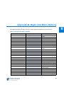
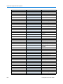
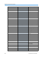
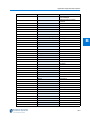
Appendix B: Right click Menu Options
38
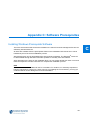
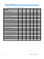
Appendix C: Software Prerequisites
39
Installing Windows Prerequisite Software . . . . . . . . . . . . . . . . . . . . . . . . . . . . . . . 39-1
Verifying Successful Installation of Prerequisite Software . . . . . . . . . . . . . . . . . . . 39-5
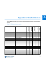
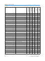
Appendix D: ASCII Character Codes
40
ASCII Character Codes . . . . . . . . . . . . . . . . . . . . . . . . . . . . . . . . . . . . . . . . . . . . . 40-1
Character Codes Chart . . . . . . . . . . . . . . . . . . . . . . . . . . . . . . . . . . . . . . . . . . . 40-2
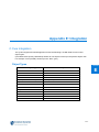
Appendix E: Integration
xvi
41
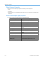
C·Cure Integration . . . . . . . . . . . . . . . . . . . . . . . . . . . . . . . . . . . . . . . . . . . . . . . . .
Object Types . . . . . . . . . . . . . . . . . . . . . . . . . . . . . . . . . . . . . . . . . . . . . . . . . . .
Object Common Properties . . . . . . . . . . . . . . . . . . . . . . . . . . . . . . . . . . . . . . . .
Access Control Object Type properties. . . . . . . . . . . . . . . . . . . . . . . . . . . . . . .
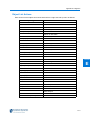
Object List Actions. . . . . . . . . . . . . . . . . . . . . . . . . . . . . . . . . . . . . . . . . . . . . . .
Object List Status . . . . . . . . . . . . . . . . . . . . . . . . . . . . . . . . . . . . . . . . . . . . . . .
41-1
41-1
41-2
41-2
41-3
41-4
victor/C·Cure Event Management . . . . . . . . . . . . . . . . . . . . . . . . . . . . . . . . . . . . .
Terminology. . . . . . . . . . . . . . . . . . . . . . . . . . . . . . . . . . . . . . . . . . . . . . . . . . . .
Use Cases. . . . . . . . . . . . . . . . . . . . . . . . . . . . . . . . . . . . . . . . . . . . . . . . . . . . .
Use Case 1 - Event Activation Occurs (Event Enabled) . . . . . . . . . . . . . . . .
Use Case 2 - User Right Click in Active Grid. . . . . . . . . . . . . . . . . . . . . . . . .
Use Case 3 - User Right Click in Active Grid. . . . . . . . . . . . . . . . . . . . . . . . .
Use Case 4 - Event Activation Acknowledged. . . . . . . . . . . . . . . . . . . . . . . .
41-6
41-6
41-6
41-6
41-6
41-7
41-7
Configuration and User Guide
Table of Contents
Use Case 5 - User Right Click on Acknowledged item (C·Cure) . . . . . . . . . .
Use Case 6 - User Right Click on Acknowledged item (victor) . . . . . . . . . . .
Use Case 7 - Event Activation Cleared . . . . . . . . . . . . . . . . . . . . . . . . . . . . .
Use Case 8 - Event Activation Cleared . . . . . . . . . . . . . . . . . . . . . . . . . . . . .
Use Case 9 - Event Acknowledged in C·Cure 9000 . . . . . . . . . . . . . . . . . . .
Use Case 10 - Event Acknowledged in C·Cure 9000 . . . . . . . . . . . . . . . . . .
41-7
41-8
41-8
41-9
41-9
41-9
End User License Agreement (EULA)
42
Index
43
xvii
Table of Contents
xviii
Configuration and User Guide
Overview of victor Unified Video Management
Solution
Introduction
victor is a unified security management system which provides a single solution to manage
recorded video from Intellex DVRs, VideoEdge NVRs and HDVRs. Access Control is also
incorporated via C·Cure 9000 and 3rd Party device integration.
The victor security management solution consists of three Windows-based software applications,
victor unified client, victor site manager and victor player.
victor unified client
The victor unified client (“the client”) provides a unified security and surveillance solution. It allows
you to view, manage and control live/recorded video from Intellex DVRs, VideoEdge NVRs and
HDVRs from a single unified client.
Integration with C·Cure 9000 and associated 3rd Party products provides Physical Security
Integration Management creating an easy to use and reactive event monitoring station.
Some key features:
• Advanced integrated policy management to control access to cameras, recorders, PTZ controls,
search and export
• Robust motion-based smart search uses meta-data to provide fast video searching and analysis
• Analytic Search feature (VideoEdge 4.2+)
• Display H.264, ACC, MJPEG and MPEG-4 video simultaneously
• Create and modify maps to show visual representation of physical locations
• Control security objects directly from maps
• Conduct time and date searches on up to ten cameras across multiple recorders
• Built in Analog and Virtual Matrix capabilities to manage up to four monitors per workstation from
a variety of CCTV keyboards
• Mix live and recorded video within the same window for real time response
1-1
1
Overview of victor Unified Video Management Solution
• Intelligent switch layout feature enables multiple monitors to quickly change screen layout for
fast response to situations.
• Built in Microsoft WPF (Windows Presentation Foundation).
• Video wall allows client workstations to share layout components.
• Monitor and manage system events and alarms.
• Interface with Third Party Devices.
• Configure Bandwidth allocation at Role and recorder level.
• Still Image Capture with E-mail/Print/Edit functionality.
• Database configuration including Journal Filtering, Input management and Archive options.
• Organize recording units and objects by site, allowing for a more intuitive management system.
The client is freely available and can be installed on as many machines as a site requires.
Licensing is managed by victor site manager based on the number of concurrent users of victor
unified client.
victor site manager
victor site manager (“site manager”) incorporates an industry-standard relational database used to
manage and maintain a single record of:
• Authorized users/passwords.
• Associated Recorders, Cameras and 3rd party devices.
• Roles and Permissions.
• Alarm and Event journals.
• Client license status.
Only one site manager is required per site regardless of the number of recorders, clients or
devices connected. The site manager can be installed on the same PC as the client for smaller
sites or on a separate server for larger sites.
The victor site manager stores data, operator profiles, role information, and tracking who, what,
and when operators interact with your video network.
The site manager Server provides a single point of access for users to manage multiple recording
devices. It utilizes SQL Server’s database functionality to provide authentication for client users, as
well as central monitoring and administration of multiple recording platforms over a Wide Area
Network (WAN).
1-2
Configuration and User Guide
Overview of victor Unified Video Management Solution
victor player
victor player is the standalone video player application which can be exported along with digitallyverified video clips to enable the playback of exported video clips in native format without requiring
the full installation of the client.
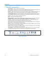
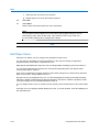
victor Command Center
The victor Command Center lets you build your own security operation center (SOC). You can
manage thousands of cameras and multiple locations, creating video walls using standard PCs.
Video walls are a key component to monitoring large camera counts. Share and communicate
information between operators and pushing live or recorded video from one monitor to another - to
ensure rapid response to critical events. You can expand your system by adding victor client and
agent licenses, to meet the needs of your organization.
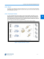
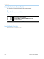
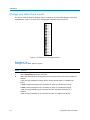
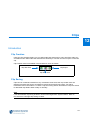
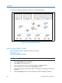
Figure 1-1 illustrates how the client integrates with existing and new system hardware.
Figure 1-1 System Overview - General
1-3
1
Overview of victor Unified Video Management Solution
victor/C·Cure Integration
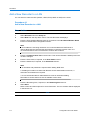
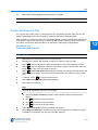
victor 4.2 supports full integration with Software House C·Cure 9000 security and Event
Management software.
Figure 1-2 System Overview - C·Cure Integration
C·Cure 9000
Software house’s ‘C·Cure 9000 Access and Event management solution’ can be integrated with
American Dynamics’ ‘victor unified video management system’.
C·Cure object types can be displayed within victor client and support the victor privilege
configuration and authorisation.
The system supports the installation of C·Cure and victor on the same operating system or on
different operating systems connected via a network. Installation of the applications does not
require a specific order and each application may be uninstalled without affecting the other.
Note
Version Compatibility - C·Cure 9000 integration requires:
- C·Cure 9000 v2.1+
- victor v4.2+
1-4
Configuration and User Guide
Installation
2
Introduction
Each victor installation is unique. You should carefully plan how you want to design and implement
your system. Relationships and dependencies between various elements of the system often
require specific sequences for configuration and installation.
Typical tasks are outlined in this document but your AD integrator should adapt the details and
sequence of your implementation to suit your specific requirements.
General
Both victor site manager and victor client software can be installed from the installation disc.
The client is freely available and can be installed on as many machines as a site requires.
Licensing is managed by victor site manager based on the number of concurrent users of victor
unified client.
Client software must be installed on every machine on the system. For smaller installations, site
manager can be hosted on a client PC, for larger installations, it is recommended site manager is
hosted on a dedicated machine.
If upgrading from a previous version, a new license is required.
The installer program installs all necessary third party software (prerequisites) first and then
installs the selected victor software.
Before the client and remote site manager can be used together, you may need to change the
default Windows Local Security Policy to ‘Classic’ on the site manager Machine. (Refer to Change
Windows Local Security Policy (Win 7))
2-1
Installation
To run the client software and site manager, the following hardware specifications are
recommended.
Note
1. Actual requirements and product functionality may vary based on your system configuration and
operating system.
2. When performing an upgrade, the installation steps will vary from those detailed below.
Specifically, during an upgrade, as the SQL database is already set up, any steps relating to
database installation are omitted.
3. In order to perform an upgrade, the original installer account will be required.
2-2
Configuration and User Guide
Installation
Change Windows Local Security Policy (Win 7)
You may need to change the Windows default Local Security Settings on the site manager Server.
The following procedure is for the recommended OS Windows 7, the procedure may vary slightly
for other operating systems.
Procedure 2-1
Change Windows Local Security Policy (Win 7)
Step
Action
2
1
Select Start on the Windows Taskbar.
2
Select Control Panel. The Control Panel displays.
3
Select System and Security.
4
Select Administrative Tools. The Administrative Tools window displays.
5
Select Local Security Policy. The Local Security Policy window displays.
6
Select Local Policies. The Local Policies folder displays.
7
Select Security Options. The Local Security Settings folder displays.
8
Select Network Access: Sharing and security model for local accounts. The Sharing
and security model for local accounts window displays.
9
Select Classic - local users authenticate as themselves from the drop down menu.
10
Select OK.
11
Close open Windows.
- End -
Installing .NET
If running Windows XP, before the installation of the victor software can begin, Microsoft .NET 3.5
must be installed.
Procedure 2-2
Installing .NET
Step
1
Action
Insert the victor DVD. If the required .NET software is not installed, the following dialog
displays ‘.NET is required to run this software.’
2-3
Installation
2
Select Yes to install .NET or No to exit. If you selected yes, wait a few seconds then
‘Please wait while Setup configures the components’ dialog displays.
3
After a few minutes ‘.NET installed successfully’ dialog displays, then select OK.
4
Once the victor splash screen displays, victor software may be installed. Refer to
Procedure 2-4 Installing victor site manager
- End -
Installation disc
The installation disc will Autorun when inserted in the CD/DVD drive and the victor unified client
install window will display.
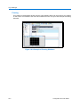
Procedure 2-3
Using the Installation DVD
Step
Action
1
Close any programs currently running.
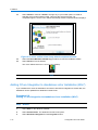
2
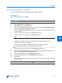
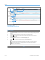
Insert the victor software DVD into the CD/DVD Drive.Figure 2-1 the Welcome to victor
install window displays.
Figure 2-1 Welcome to victor unified client Install window
If the DVD does not auto run:
2-4
Configuration and User Guide
Installation
a
Select Start on the Windows Taskbar.
b
Select Computer.
c
Explore the CD/DVD Drive
d
Double click the file InstallerSetup.exe.Figure 2-1 the Welcome to victor install
window displays.
3
If required, in the Prepare section select Review the Hardware and Software
Requirements for installation. A table detailing specifications displays.
4
Select one of the following install options in the install section:
• To install victor site manager refer to Procedure 2-4 Installing victor site
manager.
• To install victor unified client refer to Procedure 2-5 Installing victor unified client
Software.
2
Note
If installing the client and site manager on the same machine, it is recommended
that site manager be installed first.
5
If required, in the Other Information section select from the following:
• Browse this DVD- view the contents of the DVD.
• View Configuration and User Guide (.pdf)
6
Select Exit to close the window.
- End -
Installing victor site manager
Note
1. Ensure your user account has administrator privileges before beginning installation.
2. Ensure that the client and site manager are both installed using the same O/S accounts.
3. After installing the site manager, the PC/server also needs to have the client installed. This is so
victor operator accounts can be created to allow client machines to connect to the site manager.
4. For laptop installations only:
Ensure only 1 standard LAN card is enabled.
Restart the system.
Adapters can be re-enabled after installation is complete.
2-5
Installation
victor site manager prerequisites.
Please refer to Table 39-3 victor site manager prerequisites in Appendix C for a full list of
prerequisite software included in the installation.
Please consult your Information Systems personnel before connecting workstations to your
network.
Please ensure you read and understand all of the following instructions before installing site
manager. If you have any questions or difficulties, contact your dealer or Technical Support.
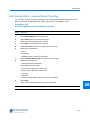
Procedure 2-4
Installing victor site manager
Step
Action
1
Close any programs currently running.
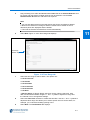
2
Insert the victor software disc into the Disc Drive. Figure 2-2 the Welcome to victor Install
window displays. If the install window does not display, refer to Procedure 2-2 Installing
.NET.
Figure 2-2 Welcome to victor Install window
2-6
Configuration and User Guide
Installation
3
Select victor site manager in the Install section. Language selector dialog displays.
Note
Depending upon your system security settings, you may be prompted to allow the
installer access to your system. Select Yes.
4
Select the language for the installation from the drop down menu.
Note
If required, the language pack for the selected language will be automatically
installed. However, if you want to use an additional language you will need to
manually install the corresponding language pack from the victor software DVD
(Browse this DVD>ISSetupPrerequisites\Microsoft .NET Framework 4.0 Full\Language Packs). For information on how to install a language pack see
Appendix C: Software Prerequisites, Installing Windows Prerequisite Software.
2
5
Select OK. The Install Shield Wizard requirements window displays.
6
If prerequisite software is required to be installed. The requirements window will display
informing you of the software required. If no prerequisite software is required, the victor
site manager Setup Wizard window displays.
7
Select Install to continue. The prerequisite software will begin its installation. Depending
what prerequisites you already have installed, you may be prompted to reboot your
computer. Welcome to the InstallShield wizard for Crossfire dialog displays.
8
Select Next. Destination folder dialog displays. Select Change to change the Install folder.
9
Select Next. Crossfire Database Server dialog displays.
10
Select either:
a
Use an existing local or remote SQL Server 2008 instance (If available)
b
Install Microsoft SQL Server 2008 R2 Express edition (if required)
or
11
Select Next. If you choose to install SQL Express 2008, this will now install and will take a
few minutes. Database server authentication dialog displays.
12
Select Next. Ready to install dialog displays.
13
Select Install. Cross fire installs. InstallShield Wizard Completed dialog displays.
14
Select Finish. The victor site manager Setup Wizard window displays.
15
Select Next. End User License Agreement (EULA) displays. Read the license agreement
carefully and Select I accept or I do not accept as applicable.
2-7
Installation
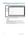
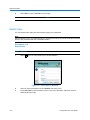
16
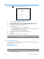
Select Next. Figure 2-3 the Ready to Install victor site manager window displays.
Ready to Install Screen
Figure 2-3 Ready to Install victor site manager window
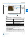
17
Select Install to continue or Back to change any of your install options. If Install is
selected the Program features install, this may take several minutes. On completion
Figure 2-4 the Setup Wizard Completed screen displays.
Setup Completed Screen
Figure 2-4 victor Setup Wizard Completed window
2-8
18
Select the Show Windows Installer log check box to view the installation details.
19
Select Finish to Exit the Wizard. The Server Configuration icon is now on your desktop.
Configuration and User Guide
Installation
20
Right click Server Configuration icon on your desktop.
21
Select Run as administrator. The Server configuration application window displays.
22
Select the Services tab.
23
Select Start Service for CrossFire Framework Service in the Framework services section.
Wait until status Running is displayed.
24
Select Start Service for CrossFire Server Component Framework Service in the
Framework services section. Wait until status Running is displayed. Extension services
remain greyed out for a few seconds then activate.
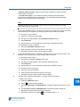
25
Select Enabled checkbox for all extension services.
26
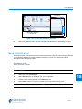
Select Start Service for all extension services. The status changes to Running.
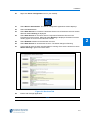
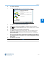
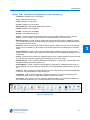
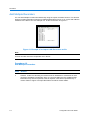
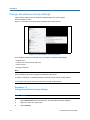
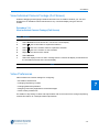
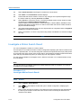
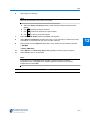
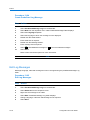
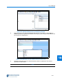
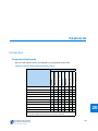
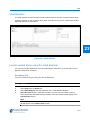
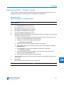
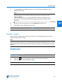
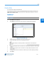
27
Confirm that all services have changed status to running. Each service should now have
Status: Running in green text next to them.
Figure 2-5 Services Tab
28
Exit the site manager application.
- End -
2-9
2
Installation
Installing victor unified client Software
victor client Prerequisites:
Refer to Table 39-3 victor client prerequisites in Appendix C for a full list of prerequisite software
included in the installation. As well as the listed prerequisites, Java and Apple QuickTime are also
required to view video from VideoEdge NVR recorders.
1
It is recommended that you Install site manager before installing the client software.
2
The workstation/server you select for the installation of the client software must be
connected to the same network and using IP addresses in the same range as that chosen
for the installation of the site manager.
Install the client software using the same O/S credentials (username and password) as those used
to install site manager.
Consult your Information Systems personnel before connecting workstations to your network.
Please ensure you read and understand all of the following instructions before installing the client
software.
Procedure 2-5
Installing victor unified client Software
Step
Action
Note
Ensure your user account has administrator privileges before beginning
installation.
1
2-10
Close any programs currently running.
Configuration and User Guide
Installation
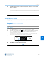
2
Insert the victor software DVD into the CD/DVD Drive. Figure 2-6 the Welcome to victor
Install window displays.
2
Figure 2-6 Welcome to victor Install window
3
In the Install Section, select victor unified client. Language selector dialog displays.
4
Select the language for the installation from the drop down menu.
Note
If required, the language pack for the selected language will be automatically
installed. However, if you want to use an additional language you will need to
manually install the corresponding language pack from the victor software DVD
(Browse this DVD>ISSetupPrerequisites\Microsoft .NET Framework 4.0 Full\Language Packs). For information on how to install a language pack see
Appendix C: Software Prerequisites, Installing Windows Prerequisite Software.
5
Select OK. The Install Shield Wizard requirements window displays.
6
If prerequisite software is required to be installed The requirements window will display
informing you of the software required. If no prerequisite software is required, the victor
site manager Setup Wizard window displays.
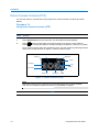
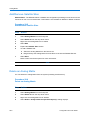
7
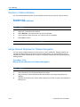
Select Install. All requirements will install then Figure 2-7 the victor unified client Setup
Wizard window displays.
2-11
Installation
Setup Welcome Screen
Figure 2-7 victor unified client Setup window
8
Select Next. The End User License Agreement (EULA) displays. Read the license
agreement carefully and Select I accept or I do not accept as applicable.
9
Select Next. The Destination folder options window displays. By default, the victor unified
client software will install to C:\Program Files\Tyco\victorClient. Select Change to browse
to a different destination folder.
10
Select Next.Figure 2-8 the Installation Options window displays. Select
next to
CCure Integration to display CCure Integration options drop down menu. Choose from:
• This feature will be installed on local hard drive - select this option if setting
up a victor and CCure unified system.
• This feature will not be available - select this option if setting up a victor
standalone system.
Note
If you install victor as standalone and want to add CCure integration at a later
date, the installation can be updated from Windows Control Panel. Refer to
Procedure 2-6 Adding C·Cure Integration to standalone victor Installation (Win7).
2-12
Configuration and User Guide
Installation
Custom Setup Screen
2
Figure 2-8 Installation Options Window
11
Select Next. The Database Location window displays. Make your selection based on
whether the site manager Database is located locally or remotely. If the database is
located remotely, choose Remote Server and enter the Server name or IP address as
appropriate.
12
Select Next.Figure 2-9 the Ready to Install victor unified client window displays.
Ready to Install Screen
Figure 2-9 Ready To Install victor unified client window
2-13
Installation
13
Select Install to continue or Back to change any of your install options. If Install is
selected, the program features install. This may take several minutes. On
completionFigure 2-10 the victor unified client Setup wizard completed window displays.
Setup Completed Screen
Figure 2-10 victor unified client Setup wizard completed window
14
Select the Show Windows Installer log checkbox to view the installation details.
15
Select Finish to Exit the Wizard.
The victor unified client icon is now on your desktop.
- End -
Adding CCure Integration to standalone victor Installation (Win7)
If you installed victor client as standalone and want to add CCure integration at a later date, the
installation can be updated from Windows Control Panel.
Procedure 2-6
Adding C·Cure Integration to standalone victor Installation (Win7)
Step
2-14
Action
1
Select Start on the Windows Taskbar.
2
Select Control Panel. The Windows Control Panel opens.
3
Select Uninstall a Program from the Programs section.
Configuration and User Guide
Installation
4
Select victor unified client.
5
Select Uninstall/Change. Figure 2-11 victor Setup Window opens
2
Figure 2-11 victor Setup Window
6
Select Next. The Program Maintenance window opens.
7
Ensure Modify is selected then select Next. The Installation Options window opens.
8
Select
menu.
9
Select This feature will be installed on local hard drive.
10
Select Next. The Database Location window displays. Make your selection based on
whether the site manager Database is located locally or remotely. If the database is
located remotely, choose Remote Server and enter the Server name or IP address as
appropriate. Select Next.
11
The Ready to Modify the Program window displays. Select Install to continue or Back to
change any of your install options. If Install is selected, the program features install. This
may take several minutes. On completion the victor unified client Setup wizard completed
window displays
12
Select Finish to exit the wizard.
next to CCure Integration to display CCure Integration options drop down
- End -
2-15
Installation
Adding a new Windows user account (Win 7)
When in a workgroup environment, you must create identical Windows accounts on both the site
manager and client machines. The accounts must contain both username and password, blank
passwords are not accepted. The following procedure is for the recommended OS Windows 7, the
procedure may vary for other operating systems.
Note
When a new Windows O/S user has been set up, that user should log into windows to ensure the
required folder structures are in place for exporting clips.
Procedure 2-7
Adding a new Windows user account (Win 7)
Step
Action
1
Select Start on the Windows Taskbar.
2
Right Click Computer.
3
Select Manage. Computer Management window displays.
4
Select Local Users and Groups.
5
Double Click Users. A List of users displays.
6
Select More Actions.
7
Select New User. New User dialog box displays.
8
Enter Credentials as required. (Password required)
9
Select Create.
- End -
2-16
Configuration and User Guide
Installation
Apply for victor License
By default, you will receive a trial period of 60 days from the date of installation. After 60 days the
trial period will expire and you must register the product to continue using it.
Note
1. Registration requires an internet connection.
2. Access to a valid email account.
3. For laptop installations only:
Ensure only 1 standard LAN card is enabled.
Restart the system.
Adapters can be re-enabled after installation is complete.
2
The System Information file must be generated on the machine for which the license is intended.
The XML file contains information unique to the machine on which it was generated and therefore
the license created is exclusive to that machine and will not work on any other.
The table below details features included with a standard victor unified client license and those
features requiring additional license purchase.
Table 2-1 License Requirements
Standard Features
Purchasable Options
Support for unlimited Intellex recorders
Option for additional concurrent victor Unified
Clients to any base model
Support for unlimited VideoEdge Recorders
Option for additional concurrent victor Agents
to either vCC options
Support for unlimited HDVR Recorders
Support for unlimited Exacq recorders
Maps
Bosch integration
Sur-gard integration
Client-to-Client Display
MZX Fire Detection integration
C·Cure 9000 Unified Install
4100U Fire Detection integration
Note
Owners of a victor license who wish to upgrade and integrate C·Cure 9000 on the
same host machine must purchase an integrated license.
2-17
Installation
Procedure 2-8
Apply for victor License
Step
Action
1
Right click the Server Configuration icon on the desktop.
2
Select Run as Administrator. The Server Configuration Application window displays.
Figure 2-12 Server Configuration Application Window
3
Select Licensing tab.
4
Select Generate System Information. The Save As window displays.
5
Enter File name in the text box.
6
Browse to a suitable folder to which the file will be saved.
7
Select Save. An .xml file is generated and saved to the location specified.
8
Visit http://www.americandynamics.net/Support/RegisterDefault.aspx and complete the
registration form.
Note
It may take one business day to receive your license.
- End -
2-18
Configuration and User Guide
Installation
Activate victor License
When the .LIC license file has been received and applied, the 60 day trial period will no longer
apply.
Procedure 2-9
Activate victor License
Step
Action
1
Save the .LIC license file to a local directory.
2
Right click the Server Configuration icon on your desktop.
3
Select Run as Administrator. The Server Configuration Application window displays.
4
Select Licensing tab.
5
Select Add new license. The Open window displays.
6
Browse to the .LIC license file and select Open.
7
The victor unified client will no longer run on a trial basis.
Note
1. If issues are encountered, please refer to the licensing instructions .PDF, included with the
license email.
2. After adding the new license file, the victor site server services need to be restarted. This can be
done manually using the victor site manager application or by rebooting the site manager server.
- End -
2-19
2
Installation
2-20
Configuration and User Guide
Getting Started
3
Introduction
This section describes how to get started using the client software to view live video after
installation.
It also provides an overview of the main Graphical User Interface (GUI) elements.
Starting site manager Services
Services
victor site manager services are stopped by default, these need to be started to ensure full
functionality of the client is available.
Note
CrossFire Framework and CrossFire Server services must be started first to allow the extension
services to run.
3-1
Getting Started
Procedure 3-1
Starting the site manager Services
Step
1
Action
Double click the victor site manager icon on the desktop. The Server Configuration
Application window displays.
Note
Depending upon security settings, you may need to right click the victor site
manager icon and select Run as Administrator.
2
Select the Services tab.
3
Select Start Service for CrossFire Framework Service in the Framework services
section. Wait until status Running is displayed.
4
Select Start Service for CrossFire Server Component Framework Service in the
Framework services section. Wait until status Running is displayed. Extension services
remain greyed out for a few seconds then activate.
5
Select Enabled checkbox for all extension services.
6
Select Start Service for all extension services. The status changes to Running.
7
Confirm that all services have changed status to running. Each service should now have
Status: Running in green text next to them.
8
Exit the site manager application.
- End -
3-2
Configuration and User Guide
Getting Started
Server Components
Site manager server components services are stopped by default. The General Purpose Interface
component needs to be enabled to ensure full functionality of the General Purpose Interface.
Procedure 3-2
Starting the General Purpose Interface Component
Step
1
Action
Double click the victor site manager icon on the desktop. The Server Configuration
Application window displays.
Note
In some circumstances you may have to right click the victor site manager icon
and select Run as Administrator.
3
2
Select the Server Components tab.
3
Select the Enabled checkbox for the General Purpose Interface server component.
4
Click Start Service. The Status changes to Running.
5
Exit the site manager application.
- End -
Starting the client
Note
1. site manager services need to be running before the client can be launched.
2. Initial sign in must be from the windows user account which was used to install the client. During
installation, an initial client user account is set up within the client using the credentials of the
Windows installer which was used to install the client. This ‘default’ account has administrator
privileges.
Procedure 3-3
Starting the client
Step
1
Action
Double Click the victor unified client icon on the desktop.
3-3
Getting Started
The client sign in screen displays. (Unless this is the first sign on in which case the client
will automatically start without requesting credentials.)
2
Select Domain/site manager textbox.
3
Enter the name of the Domain/Site Manager as required.
4
Enter Username in the Username text box. (Windows Username of installer account if this
is the first login)
5
Enter Password in the Password text box. (Windows Password of the installer account)
Note
Blank passwords are not accepted - the windows account must be assigned a
password.
6
Select site manager from the site manager dropdown.
7
Select OK to login or Exit to cancel.
- End -
3-4
Configuration and User Guide
Getting Started
Exploring the Default Workspace
The default Layout for victor is made up of a ribbon bar comprising Home, Setup and Build tabs.
The Device List and the surveillance window are the other two major components of the default
layout with the status bar displaying system information.
Home Tab - User control buttons including:
• Add - Use to add applications.
• Reports - Use to display journal and audit log information about the system.
• Switch - Prompts you to select a new layout.
• Refresh - Reloads the current layout.
• Maps - Displays the Maps List.
• Activity - Lists all the active messages in the system.
• Silence - Mute active alarms.
• Event viewer - Display all active and acknowledged events in the system.
3
• Log General Message - Use to log a message for any event in the activity viewer.
• Call ups - View, edit and run Tours, Salvos and Saved Views.
• Clips - View and verify previously stored video clips. View Vault List and Vault Explorer.
• Search and Retrieve - Execute Search and Retrieve wizard.
• Surveillance - View video.
• Event Priority Window - Displays video from Camera Call ups.
• Activate Virtual Matrix - Select a virtual matrix to display.
• Devices - Display Device List.
• Sites - Display site list.
• Web - Launch web browser.
Figure 3-1 Home Tab
3-5
Getting Started
Build Tab - Tools Include:
• Site Managers - Use to configure site managers.
• Video Actions - Create or show all video actions. Additional options such as edit and delete can
be accessed by right clicking on video actions displayed on the show all list.
• Events - Create or show all events, also change the state of events. Additional options such as
edit and delete can be accessed by right clicking on events displayed on the show all list.
• Predefined Message Log - Create and display custom messages. Additional options such as
edit and delete can be accessed by right clicking on messages displayed on the show all list.
• Layout - Use to Save, Save as and Show all layouts.
• Maps - Import, Edit and Display map files.
• Display Actions - Create or show all Map actions. Additional options such as edit and delete
can be accessed by right clicking on video actions displayed on the show all list.
• Operator - Create or show all operators. Additional options such as edit and delete can be
accessed by right clicking on operators displayed on the show all list.
• Role - Create or show all roles. Additional options such as edit and delete can be accessed by
right clicking on roles displayed on the show all list.
• Salvos - Create or show all salvos. Additional options such as edit and delete can be accessed
by right clicking on salvos on the show all list.
• Tours - Create or show all tours. Additional options such as edit and delete can be accessed by
right clicking on tours displayed on the show all list.
• Virtual Matrix - Create or show all virtual matrices. Additional options such as edit and delete
can be accessed by right clicking on virtual matrices displayed on the show all list.
Figure 3-2 Build Tab
3-6
Configuration and User Guide
Getting Started
Setup Tab - System Configuration tools including:
• Controller - Displays a list of Controllers
• Door - Displays a list of Doors
• Input - Displays a list of Inputs
• Cluster - Display a list of Clusters
• Manual Actions - Manipulate 9000 Manual Actions
• Output - Display a list of Outputs
• Reader - Display a list of Readers
• Events - Manipulate 9000 Events
• Device - Create or Show All General Purpose Devices. Additional options such as edit and
delete can be accessed by right clicking on devices displayed on the show all list.
• Monitoring Point - Create or Show All General Purpose Monitoring Points. Additional options
such as edit and delete can be accessed by right clicking on General Purpose Monitoring Points
displayed on the show all list.
• Protocol - Create or Show All General Purpose Protocols. Additional options such as edit and
delete can be accessed by right clicking on General Purpose Protocols displayed on the show
all list.
• Action Message - Create or Show All Action Messages. Additional options such as edit and
delete can be accessed by right clicking on General Purpose Action Messages displayed on the
show all list.
• Action - Create or Show All Actions. Additional options such as edit and delete can be accessed
by right clicking on General Purpose Actions displayed on the show all list.
• System Values - Use to configure Bandwidth Configuration, Journal Filter, E-mail Preferences,
Database Settings and Video Preferences.
• Analog Matrix - Create or Show All Analog Matrix Configurations. Additional options such as
edit and delete can be accessed by right clicking on Analog Matrices displayed on the show all
list.
• Cameras - Show all cameras. Additional options such as edit and view can be accessed by right
clicking on cameras displayed on the show all list.
• Keyboards - Add or show all keyboards. Additional options such as edit and delete can be
accessed by right clicking on keyboards displayed on the show all list.
• Recorders - Add, import or show all recorders. Additional options such as edit and delete can
be accessed by right clicking on recorders displayed on the show all list.
Figure 3-3 Setup Tab
3-7
3
Getting Started
Status Bar - Displays system information including:
• Number of active alerts.
• Server name (site manager).
• Client Messages.
• Active operator.
• Active Layout.
• Bandwidth Configuration.
• Active Virtual Matrix.
• Workstation Status (CPU usage / Memory Free / Disk Space Free)
• Current Date and Time.
• Any error messages detected by the client will also be displayed. For example ‘Recorder has
reached its maximum number of clients’.
Figure 3-4 Status Bar
Device List - Configure devices including:
• Recorders - Edit, delete, view, send to and refresh can be accessed by right clicking on
recorders displayed on the Device List.
• Workstations - Edit, Delete, log operator out, Identify monitors and Refresh device can be
accessed by right clicking on workstations displayed on the Device List.
• Cameras - Edit, view, send to, Search and Retrieve and refresh can be accessed by right
clicking on cameras displayed on the Device List.
• Keyboards - Edit, delete and refresh can be accessed by right clicking on keyboards displayed
on the Device List.
• Analog Matrices - Edit, Delete and Refresh can be accessed by right clicking on the analog
matrix displayed in the device list.
• General Purpose Devices - Edit, Delete and Refresh can be accessed by right clicking on the
devices displayed in the device list.
• General Purpose Monitoring Point - Edit, Delete and Refresh can be accessed by right clicking
on the monitoring points displayed in the device list.
• Monitors - Edit, Delete and Rename can be accessed by right clicking on the monitors displayed
in the device list.
• C·Cure and other 3rd Party devices.
The Home, Setup and Build tabs are fixed. All other components can be added/removed and
configured according to user preferences. Refer to Layout Manager for more information.
3-8
Configuration and User Guide
Getting Started
Save and Close options
When editing or creating an object, there are several save options available. Select the relevant
option from the following:
Save and close
Close editor without
Saving changes
Save (Apply)
Save and Create new Object
Figure 3-5 Save and Close options
• Save the current object and close the editor. Use this action to save changes which have
been made and close the object editor.
• Apply (Save) Use this action to save changes which have been made but keep the editor open,
allowing further changes to be made.
• Save the current object and create a new object in the editor. Use this action to save
changes which have been made and also open a new editor enabling a new object of the same
type to be created.
3
• Close the editor without saving the object. Use this action to cancel changes and exit the
editor.
- End -
Switch Language/Culture
You can change the language/culture of the text displayed within the application from those
selected during installation.
Procedure 3-4
Switch Language/Culture
Step
Action
1
Select victor menu
button on top left of GUI. Dropdown menu displays.
2
Select languages
3
Select the Dropdown menu in the language dialog.
4
Select the required language.
5
Select Select. Dialog displays informing you the next time you run this program, the User
Interface will be in the selected language.
6
Close the victor program.
7
Restart the victor program. GUI will display in selected language.
button. Language selection dialog displays.
- End -
3-9
Getting Started
Reposition the Quick Access Toolbar
You can reposition the Quick Access toolbar to above or below the ribbon.
Procedure 3-5
Reposition the Quick Access Toolbar
Step
Action
1
Select
from the top left of the client window.
2
Select Show Below the Ribbon or Minimize the Ribbon as required.
3
Select
to reverse the selection.
- End -
Log Out/Switch Operator
Refer to Procedure 31-10 Operator Logout.
3-10
Configuration and User Guide
Recorders
Introduction
Recorders can be added to the system manually or multiple recorders may be added using the
Recorder Import function. Recorders can be added from local area networks (LANs) or wide area
networks (WANs).
Ensure time is synchronized between client machines and network recorders. Recorders which
are out of time synchronization with client machines cause incorrect video retrieval. It is
recommended an NTP server is used to synchronize machines.
4-1
4
Recorders
Add a New Recorder to a LAN
You can add new LAN recorders (Intellex, HDVR, Exaq HDVR or NVR) to the client.
Procedure 4-1
Add a New Recorder to a LAN
Step
Action
1
Select Recorders from the Setup tab.
2
Select New from the drop down menu. The New Recorder tab displays.
3
Enter the Fully Qualified Domain Name or IP Address in the IP Address/Domain Name
text box in the Recorder Configuration section.
Note
If an IP address is not being used then it is recommended that a DNS server is
used to allow both the client and the site manager to resolve the device name. It is
not recommended to use local host files to resolve device names.
4
Enter the Communication Port in the text box. This can be left blank if default ports have
not been changed.
5
Enter the User Name, if required, in the User Name text box.
6
Enter the Password, if required, in the Password text box.
Note
1. A username and password is required when adding NVR units.
2. If adding an Intellex 5 recorder with Remote Access Authorization turned on, a
Username and Password is required.
3. It is recommended that an Administrator account is used when adding
Recorders to ensure that full access is available via the client.
7
Enter the Streaming Port, if required, in the Streaming Port text box.
8
Select Save.
Refer to Save and Close options for more information. The new recorder will be displayed
in the Device List.
- End -
4-2
Configuration and User Guide
Recorders
Add a New Recorder to a WAN
You can add new WAN recorders (Intellex, HDVR or NVR) to the client.
Procedure 4-2
Add a New Recorder to a WAN
Step
Action
1
Select Recorders from the Setup tab.
2
Select New from the drop down menu.
3
Enter the Fully Qualified Domain Name or IP Address in the IP Address/Domain Name
text box in the Recorder Configuration section.
4
Enter the Communication Port in the text box. This can be left blank if default ports have
not been changed.
5
Enter the User Name, if required in the User Name text box.
6
Enter the Password, if required in the Password text box.
Note
1. A username and password is required when adding NVR units.
2. If adding an Intellex 5 recorder with Remote Access Authorization turned on, a
Username and Password is required.
3. It is recommended that an Administrator account is used when adding
Recorders to ensure that full access is available via the client.
4
7
Enter the Streaming Port if required in the Streaming Port text box.
8
Expand the WAN Configuration section and enter the Fully Qualified Domain Name or IP
Address in the IP Address/Domain Name text box.
9
Enter the Streaming Port in the Streaming Port text box.
10
Enter the Communication Port in Communication Port text box.
11
Select Save.
Refer to Save and Close options for more information. The new recorder will be displayed
in the Device List.
- End -
4-3
Recorders
Add Multiple Recorders
You can add multiple recorders simultaneously using the import recorders function. This function
imports recorder information (minimum IP address/Hostname) from a .txt or csv file and adds the
recorders to the Device List. An example of a .txt file can be seen in Figure 4-1.
Figure 4-1 Example of an Import LAN Recorders .txt file
Note
1. Lists are not case sensitive.
2. Each recorder must have a separate row in the list.
Procedure 4-3
Add Multiple Recorders
Step
1
4-4
Action
Create a .txt file/.csv file listing at a minimum the IP addresses or hostnames of each
recorder to be added. Create each entry on a new line within the file. Additional field
information may also be imported, enter as required, each field is represented by a
comma. Refer to Figure 4-2 Import Recorders Format for further details.
Configuration and User Guide
Recorders
Figure 4-2 Import Recorders Format
2
Save the .txt file/.csv file.
3
Select Recorders from the Setup tab.
4
Select Import Recorders from the drop down menu. Please select a file to import
dialog box displays.
5
Navigate to the location of the saved .txt file/.csv file.
6
Select the .txt file/.csv file.
7
Select Open. The imported recorders will display on the Device List.
4
When a recorder has been added to the Device List the details can be edited. Refer to
Procedure 4-4 Edit a Recorder. for further information.
- End -
Edit a Recorder
You can edit the properties of recorders (Intellex, VideoEdge NVRs or HDVRs) previously added
to the system.
Procedure 4-4
Edit a Recorder
Step
1
Action
Select Recorders from the Setup tab.
4-5
Recorders
2
Select Show all. All available recorders are listed.
3
Right click on the recorder to be edited.
4
Select Edit. The Recorder Editor displays.
5
Make edits as required.
The following properties can be edited:
Table 4-1 Editable Recorder Properties
Intellex
NVR
HDVR
Description
Description
Description
IP Address/Domain Name
User Name
User Name
User Name
Password
Password
Password
IP Address/Domain Name
IP Address/Domain Name
Communication Port
Communication Port
Communication Port
Alerts Port
Streaming Port
Alerts
Alerts
Alerts
IP Address/Domain Name
(WAN)
IP Address/Domain Name
(WAN)
IP Address/Domain Name
(WAN)
Communication Port
(WAN)
Communication Port
(WAN)
Communication Port
(WAN)
Streaming Port (WAN)
Streaming Port (WAN)
Alerts Port (WAN)
6
Select Save.
Refer to Save and Close options for more information.
- End -
4-6
Configuration and User Guide
Recorders
Configure VideoEdge NVR (4.2+)
victor client supports configuration of VideoEdge NVR 4.2+. From the client GUI you can change
configuration settings for:
Cameras
List
Alarms
Scheduler
Passwords
Discovery
Storage
Basic
Advanced
System
General
Roles
Licensing
Templates
Backup/Restore
Network
General
LAN Interface
DHCP Server
WAN Settings
Bandwidth Throttling
Advanced
Failover
Update Software
Storage Statistics
Logs
Dark Image Detection
E-mail Alerts
Connected Clients
Reset to Factory Defaults
Shutdown
4
Note
This feature is not available if a Switch User or Operator Logout operation has been performed.
Procedure 4-5 Configure VideoEdge NVR (4.2+)
Step
Action
1
Select Recorders from the Setup tab.
2
Select Show all. All available recorders are listed.
3
Right click the recorder to be configured.
4
Select Configure. The recorders configuration page opens.
5
Refer to the recorders User/Administrator guide for configuration help.
- End -
4-7
Recorders
Change Bandwidth Configuration settings
You can configure bandwidth to reflect the capabilities of your network.
Bandwidth is selected from a list of network types which define a maximum bit-rate value to be
received from video servers.
The client allocates a bandwidth limit to each individual active stream by intelligently distributing
the total bandwidth limit associated with the chosen network type.
The ability to change bandwidth type is based on the role allocated to the active user.
Current bandwidth is displayed on the status bar. A visual indicator displays in real time how much
CPU resource is in use. Refer to Figure 4-3 Status Bar.
Current Bandwidth Configuration
Figure 4-3 Status Bar
Note
Bandwidth throttling may degrade video quality.
Procedure 4-6
Change Bandwidth Configuration settings
Step
Action
1
Select the current Bandwidth Configuration from the Status bar. Refer to Figure 4-3 Status
Bar. Bandwidth settings display as a popup menu.
2
Select the required Bandwidth setting. Options are:
.
Bandwidth Configuration
Bandwidth Cap
Local Area Network (LAN)
Capped by local network capabilities
High Speed Broadband
10 Mbps
Broadband
5 Mbps
Low Speed Broadband
1 Mbps
Fractional T1
512 Kbps
Narrowband
256 Kbps
Modem
128 Kbps
Table 4-2 Bandwidth Configuration
4-8
Configuration and User Guide
Recorders
The selected Bandwidth is applied and will display on the task bar.
Note
1. When bandwidth throttling is being applied, the
symbol displays on the video stream.
2. When a stream has been stopped due to client bandwidth configuration, the
symbol
displays on the video stream.
- End -
Virtual Private Network (VPN)
When using a VPN connection, selecting the VPN option informs the NVR that the client machine
is on a WAN. This selection makes transcoding resources available, if configured and/or free.
Displaying Recorders
4
You can display all recorders (Intellex, NVR or HDVR) that have been added to the system.
Procedure 4-7
Displaying Recorders
Step
Action
1
Select Recorders from the Setup tab.
2
Select either Show all to show all recorders, Online to show Online recorders or Offline
to show Offline recorders only.
A new tab displays listing the recorders selected.
- End -
4-9
Recorders
Delete a Recorder
You can delete recorders (Intellex, NVR or HDVR) from the system when they are no longer
required.
Procedure 4-8
Delete a Recorder
Step
Action
1
Select Recorders from the Setup tab.
2
Select either Show all to show all recorders, Online to show Online recorders or Offline
to show Offline recorders only.
3
Right click on the recorder to be deleted.
4
Select Delete. You will be prompted to confirm the deletion.
5
Select Yes to delete or No to cancel.
- End -
View all Cameras on a Recorder
You can view all cameras associated with a recorder.
Procedure 4-9
View all Cameras on a Recorder
Step
Action
1
Select Devices from the Home tab. The Device List displays.
2
Select
next to Recorders to expand the selection.
3
Select
next to the recorder folder to expand the selection.
4
Right click the recorder to be viewed.
5
Select View. Live video from all cameras connected to that recorder will display in the
surveillance window.
- End -
4-10
Configuration and User Guide
Recorders
Refresh all Recorders
You can perform a refresh on all recorders.
Procedure 4-10
Refresh all Recorders
Step
Action
1
Select Devices from the Home tab. The Device List displays.
2
Right click on Recorders.
3
Select Refresh.
- End -
Refresh Individual Recorders
4
You can perform a refresh on individual recorders.
Procedure 4-11
Refresh Individual Recorders
Step
Action
1
Select Devices from the Home tab. The Device List displays.
2
Select
next to Recorders to expand the selection.
3
Select
next to the recorder folder to expand the selection.
4
Right click on the recorder to be refreshed.
5
Select Refresh (Device type).
- End -
4-11
Recorders
4-12
Configuration and User Guide
Cameras
Introduction
After adding recorders, their associated cameras are then available to view and configure. Names
and Descriptions of cameras may be changed within the client and various camera lists may be
viewed. Other camera properties can generally be viewed within the client but not changed.
5
Show all Cameras
You can display a list of all cameras available on the system. Refer to Object Lists for more
information.
Procedure 5-1
Show all Cameras
Step
Action
1
Select Cameras in the Setup tab.
2
Select Show all from the drop down menu. The cameras tab displays listing all available
cameras. Refer to Object Lists for display and export options.
- End -
5-1
Cameras
Show all Online Cameras
You can display a list of all cameras which are currently online. Refer to Object Lists for more
information.
Procedure 5-2
Show all Online Cameras
Step
Action
1
Select Cameras in the Setup tab.
2
Select Online from the drop down menu. The cameras tab displays listing all online
cameras. Refer to Object Lists for display and export options.
- End -
Show all Offline Cameras
You can display a list of all cameras which are currently offline. Refer to Object Lists for more
information.
Procedure 5-3
Show all Offline Cameras
Step
Action
1
Select Cameras in the Setup tab.
2
Select Offline on the drop down menu. The cameras tab displays listing all offline
cameras. Refer to Object Lists for display and export options.
- End -
5-2
Configuration and User Guide
Cameras
Edit a Camera
Camera Names and Descriptions may be edited and Alerts and Associations can be added.
Note
Changing the name of a camera at the recorder will not change the name of the camera in victor
unless the recorder is re-imported.
Procedure 5-4
Edit a Camera
Step
Action
1
Select Devices from the Home tab.
2
Select
next to Recorders in the Device List window.
3
Select
next to the recorder folder to expand the selection.
4
Select
next to the recorder.
5
Right click on the camera to be modified.
6
Select Edit.
7
Expand the General section.
a
Edit the Name, if required, in the Name textbox.
5
Note
Changing the Camera name assigns a Pseudo Name to the camera. It is changed
only within the client, the change is not recognized on the recorder.
8
b
Enter the Description, if required, in the Description text box.
c
Select the Enabled check box to enable or deselect to disable. The default setting is
enabled.
Expand the Alerts section. You can attach an object to the following alert types:
5-3
Cameras
Table 5-1 Camera Alerts
Intellex
VideoEdge NVR
HDVR
User Alarm
Motion Detection
Motion Detection
Video Loss
Video Loss
Video Loss
Motion Detection
Dry Contact
Dry Contact
Motion Exception
User Panic
Perimeter Protection
Object Detection
Light Change
Direction
Text Exception
Linger
External Alarm
Enter
Exit
Abandoned/Removed
9
Expand the Status section to display the current Alert Status.
10
Expand the Associations section. You can associate the camera with up to 5 objects.
Refer to Procedure 16-1 Associate Objects.
11
Select Save.
Refer to Save and Close options for more information.
- End -
Reset Camera Name
When a camera name is changed in the client, it can be reset back to the original name assigned
at the recorder.
Procedure 5-5
Reset Camera Name
Step
5-4
Action
1
Select Devices from the Home tab.
2
Select
next to Recorders in the Device List window.
3
Select
next to the recorder folder to expand the selection.
4
Select
next to the recorder.
5
Right click on the camera to be modified.
6
Select Reset Name.
7
Right Click the camera.
Configuration and User Guide
Cameras
8
Select Refresh. Camera Name will revert to that assigned at the recorder.
Note
All Camera names can be reset by selecting Cameras from the Setup tab and
Reset All Name(s).
- End -
5
5-5
Cameras
5-6
Configuration and User Guide
Device List
Introduction
The Device List forms part of the default layout. It displays all the hardware devices (objects)
configured in the system and can be used to configure objects, with interaction primarily via their
context menus.
Object Status
An Object’s Online/Offline status is visually represented by a graphical light bulb associated with
the object’s icon in the device list. The following objects support this feature:
• Cameras
6
• Keyboards
• Analog Matrices
6-1
Device List
• Recorders
Object
Online
Offline
Unknown
Camera
Keyboard
Analog Matrix
Recorder
Note
1. For analog cameras, Online and Offline status refers to the physical connection between the
camera and the recorder.
2. Cameras displaying
(Offline status) may still be streaming video, the system may take
some time to refresh the icon to Online.
Alarm Persistence
VideoEdge NVR constantly caches alarms from the previous two weeks. This means if an NVR
loses connection to site manager, alarms are resent upon reconnection in Recovery mode.
Upon reconnection, notification is sent to victor that Alarm recovery is in progress and also informs
whether it has been successful.
Users must run a Video Alarm report query using report to access the alarms. Refer to Procedure
33-1 Generate System Reports.
Alarm persistence can be disabled by selecting the Skip Recovered Events checkbox on the Site
Manager Settings tab. If the status of the Skip Recovered Events checkbox is changed while the
VideoEdge driver service is running, it must be stopped and restarted before changes take effect.
Note
Alarm persistence is only available on VideoEdge 4.2+ and victor client 4.2+
6-2
Configuration and User Guide
Device List
Display Device List
The Device List, which forms part of the default layout, displays all hardware configured in the
system available to the current user.
Procedure 6-1
Display Device List
Step
Action
1
Select Devices from the Home tab. Figure 6-1 illustrates a typical Device List view.
2
The Device List window displays showing all devices configured within the system.
Device Type
Root Node for
each type of device
All Devices
victor Object
Analog Matrices
Recorders
Controllers*
General Purpose Devices
Workstations
Cameras
Right click object to
access its context menu
Keyboards
6
Doors*
Inputs*
Readers*
Outputs*
General Purpose
Monitoring Points
* Available with C·Cure Integration only
Figure 6-1 Device List
- End -
6-3
Device List
View Devices by Device type
The device list uses class folders to organise objects within the device list into Parent/Child format.
Objects can be filtered by the device types such as Workstations, Cameras, Recorders or
Keyboards.
Procedure 6-2
View Devices by Device Type
Step
Action
1
Select Devices from the Home tab.
The Device List window displays showing all devices configured within the system.
2
Select the device type to be viewed:
Table 6-1 Device Types
Device Type
Icon
All Devices
Analog Matrices
Recorders
Controllers*
General Purpose Devices
Workstations
Cameras
Keyboards
Doors*
Inputs*
Readers*
Outputs*
General Purpose Monitoring Points
*Integration only
Device list displays only the type selected.
- End -
6-4
Configuration and User Guide
Surveillance
Introduction
The Surveillance feature allows users to view live or recorded video streams from recording
devices. Live video may be viewed within the pane configurations available in the surveillance
window or by using call ups to display video from prearranged camera configurations. The main
surveillance window can be organized according to any of the layouts configured and stored on
the site manager. The default layout may be changed at any time by selecting a new layout from
the options in the layout control.
Additional 'pop-up' video windows can be created and moved to additional monitors connected to
the workstation.
Video Preferences editor enables you to:
• Stop video and audio from streams which are not visible
• Display times in UTC (Coordinated Universal Time)
• Assign a Third Party Application with which to edit still images.
• Edit video overlay preferences (font size/color).
Where a client determines the streams in the selected video pane(s) support streaming playback
the instant playback controls will be enabled allowing the user to navigate through the streams.
7-1
7
Surveillance
PTZ Control via the Surveillance Window
When viewing a video stream, Pan, Tilt, Zoom (PTZ) and instant playback operations can be
performed.
Note
Focus, Iris Control and Patterns are not supported on HDVR Units
There are two types of PTZ command that the client will determine to use, these are:
Real PTZ
This is used with a live stream from a dome camera which supports PTZ commands.
Virtual PTZ
This is used with a live or recorded stream from any fixed camera. Virtual PTZ is achieved by
capturing a specific area of the camera’s view, then cropping a smaller area and zooming that to a
larger view.
Bandwidth Configuration
Bandwidth allocation can be configured from the status bar to enable throttling of bandwidth.
Note
Bandwidth throttling is not available on HDVR units, however, any streams exceeding the client
bandwidth cap will be stopped.
View Live Video from all Cameras on a Recorder
You can view live video from all online cameras connected to a recorder.
Note
The maximum number of supported live video feeds is: 16 H.264 @ 30ips.
Procedure 7-1
View Live Video from all Cameras on a Recorder
Step
7-2
Action
1
Select Devices from the Home tab. The Device List window displays.
2
Select
next to Recorders to expand the selection.
3
Select
next to the recorder folder to expand the selection.
4
Right Click the recorder to be viewed.
Configuration and User Guide
Surveillance
5
Select View. A new surveillance tab opens displaying all available camera views.
- End -
Display Live Video from Selected Cameras
You can view Live Video on the surveillance pane from selected cameras.
Procedure 7-2
Display Live Video from Selected Cameras
Step
Action
1
Select Surveillance from the Home tab. The Surveillance window displays.
2
Select the required Video Pane Layout icon to set the pane configuration. Default view is
1x1.
3
Select Devices from the Home tab. The Device List window displays.
4
Select
next to Recorders to expand the selection.
5
Select
next to the recorder folder to expand the selection.
6
Select
next to the required recorder to expand the selection.
7
Drag and Drop the camera into the surveillance pane of your choice. The surveillance
pane updates to display the live video feed from the selected camera.
8
Repeat steps 5 to 6 to add more cameras to the surveillance pane windows.
- End -
7
7-3
Surveillance
Change Surveillance Overlay Settings
Video Overlay settings can be enabled or disabled within the video window.
Overlay settings include:
Figure 7-1 Surveillance Overlay options displays the Overlay options.
Figure 7-1 Surveillance Overlay options
Four separate elements of overlays can be enabled or disabled independently:
• Display Grid
• Camera, Recorder, Names and Time
• Dome Control
• Analytic Hit Boxes
Note
1. Changing to values within the overlay affects the whole window in which the changes are made.
Overlay settings cannot be changed for individual video panes.
2. Refer to Procedure 7-12 Edit Surveillance Preferences for further overlay options.
3. Grid lines can only be switched on/off when viewing multiple panes.
Procedure 7-3
Change Surveillance Overlay Settings
Step
7-4
Action
1
Select Surveillance from the Home tab. The Surveillance window displays.
2
Right click within any video pane.
3
Select Overlay.
Configuration and User Guide
Surveillance
4
To enable or disable specific surveillance overlay options, select and deselect from the
options as required.
Note
Surveillance overlay must be enabled to allow camera control from within specific
panes.
- End -
Virtual Camera Controls
You can use Virtual pan, tilt and zoom (PTZ) functions to crop and magnify specific areas of a fixed
camera’s view.
Procedure 7-4
Using Virtual Camera Controls (PTZ)
Step
Action
1
Select Surveillance from the Home tab. The Surveillance window displays.
2
within the video pane of the camera which you
Select the camera control symbol
want to control. Refer to Procedure 7-3 Change Surveillance Overlay Settings if
surveillance overlay is not visible.
Virtual PTZ controls display within the surveillance pane. Use controls by selecting
relevant areas of the overlay as seen in Figure 7-2 PTZ Controls.
.
Close
7
Zoom in
Pan/Tilt
Zoom out
Figure 7-2 PTZ Controls
3
Select Close to close the camera control overlay.
- End -
7-5
Surveillance
Dome Camera Controls (PTZ)
You can use real Pan, Tilt and Zoom (PTZ) functions to control camera movement and video
display.
Procedure 7-5
Using Dome Camera Controls (PTZ)
Step
Action
1
Select Surveillance from the Home tab. The Surveillance window displays.
2
Select
within the video pane of the dome camera you want to control. Refer to
Procedure 7-3 Change Surveillance Overlay Settings if surveillance overlay is not visible.
Dome controls display within the surveillance pane. Use the controls by selecting relevant
areas of the overlay as seen on Figure 7-3 Dome Controls (PTZ):
Pan/Tilt
Focus Near
Sequence
Zoom in
Close
Iris Open
Flip
Pattern
Iris Close
Zoom out
Focus Far
Preset
Figure 7-3 Dome Controls (PTZ)
Note
Depending upon the type of dome and recorder being used, the controls available
may vary. For example, sequence function is not available via Intellex.
- End -
7-6
Configuration and User Guide
Surveillance
Clear Video from a Surveillance Pane
You can clear video from an individual video pane within a surveillance window.
Procedure 7-6
Clear Video from a Surveillance Pane
Step
Action
1
Right click on the surveillance pane from which you want to clear the video.
2
Select Clear Video. The camera view will be cleared from the surveillance pane.
- End -
Clear all video from a Surveillance Window
You can clear video from all panes within a surveillance window. This clears all video streams from
the surveillance window which has focus but not from other windows which may be open.
Procedure 7-7
Clear all video from a Surveillance window
Step
Action
1
Right click on the surveillance window from which you want to clear all video.
2
Select Clear all videos. The camera views will be removed from the surveillance window.
7
- End -
7-7
Surveillance
Change Live Video Pane Layout
The layout of the surveillance window may be changed to accommodate different video pane
configurations. Figure 7-4 Video Pane Configurations displays the layout panes.
Figure 7-4 Video Pane Configurations
Procedure 7-8
Change Live Video pane Layout
Step
Action
1
Select Surveillance from the Home tab.
2
Select the required pane configuration from the options at the top of the surveillance
window.
• 1x1 This layout displays a single stream of wide format video on a widescreen
layout.
• 1x3w This layout displays up to 3 streams of video on a widescreen layout.
• 2x2w This layout displays up to 4 streams of video on a widescreen layout
• 2+3 This layout displays up to 5 streams of video with extra resolution on 2
streams.
• 2x3 This layout displays up to 6 streams of video on a widescreen layout.
7-8
Configuration and User Guide
Surveillance
• 2+2x2 This layout displays up to 6 streams on a widescreen layout with extra
resolution on 2 streams.
• 1+2x3w This layout displays up to 7 streams on a widescreen layout with extra
resolution on 1 stream
• 2+2x2p This layout displays up to 9 streams on a portrait layout with extra
resolution on 1 stream
• 3x4 This layout displays up to 12 streams on a widescreen layout.
• 4x4 This layout can display up to 16 streams of wide format video on a
widescreen layout.
• 1x1 This layout can display a single stream of video.
• 2x2 This layout can display up to 4 streams of video.
• Guard This layout displays up to 6 streams of video, with extra resolution on one
stream.
• 3x3 This layout displays up to 9streams of video.
• 2+8 This can layout display up to 10 streams of video with extra resolution for 2
streams.
• 4x3 This layout can display up to 12 streams of wide format video.
• 12+1 This layout can display up to 13 streams of video with extra resolution on 1
stream.
• 4x4 This layout displays up to 16 streams of video.
• 5x5 This layout displays up to 25 streams of video.
• 6x6 This layout displays up to 36 streams of video.
• 8x8 This layout displays up to 64 streams of video.
The Surveillance window changes layout accordingly.
Note
Double-click in a single video pane to display that camera feed as a 1x1 in a
separate video window.
7
- End -
7-9
Surveillance
Close Surveillance Window
You can close the surveillance window if it is no longer required.
Procedure 7-9
Close Surveillance Window
Step
Action
1
Right click on the tab of a tabbed window.
2
Select Close.
OR from within a floating or dockable window:
3
Select
on the top right of the window. Window closes.
- End -
View Individual Camera Footage
Instead of dragging and dropping individual cameras into a surveillance window, you can view
footage from a specific camera more conveniently by using its context menu.
Procedure 7-10
View Individual Camera Footage
Step
Action
1
Select Devices from the Home tab. The Device List displays.
2
Select
next to Recorders to expand the selection.
3
Select
next to the recorder folder to expand the selection.
4
Select
next to the recorder to view cameras.
5
Right click the camera to be viewed.
6
Select View. Footage from that camera will display in a new surveillance window.
- End -
7-10
Configuration and User Guide
Surveillance
View Individual Camera Footage (Full Screen)
Instead of dragging and dropping individual cameras into a surveillance window, you can view
footage from an individual camera maximized on any connected display using the Send to
Feature.
Procedure 7-11
View Individual Camera Footage (Full Screen)
Step
Action
1
Select Devices from the Home tab. The Device List will display.
2
Select
next to Recorders to expand the selection.
3
Select
next to the recorder folder to expand the selection.
4
Select
next to the recorder to view cameras.
5
Right click the camera to be viewed.
6
Select Send To.
7
Select the display to send to video. Footage from the camera will display as maximized in
the surveillance window of the chosen display.
- End -
Video Preferences
Video Preferences includes settings for configuring:
• Surveillance Preferences
• Changing Clip Saving Location
7
• Changing default Clip Duration
• Assigning Third Party Applications to edit Still Images
• Video Overlay Preferences
For details on Clip Saving Location and Clip Duration refer to Procedure 34-3 Change Clip Saving
Location/Procedure 34-2 Change Default Clip Duration.
7-11
Surveillance
Surveillance Preferences
Surveillance preferences includes options to:
Stop video and audio when not visible: Enabling this setting reduces network traffic as video is
not streamed through the network in surveillance windows which do not have focus. By default this
is enabled.
Display times in UTC: Enabling this (Universal Time Coordinated) setting changes the time
displayed in surveillance windows from that taken from the recorder to a standardized,
synchronized value. (No information about time zones or daylight saving time is transmitted.)
Default is disabled.
Edit Surveillance Preferences
Surveillance settings can be changed to reduce network traffic, standardize time and make overlay
text clearer.
Procedure 7-12
Edit Surveillance Preferences
Step
Action
1
Select System Values from the Setup tab. System Values window displays.
2
Select Video Preferences.
3
In the Surveillance Preferences section select from the following to enable or disable the
features:
• Stop Video and Audio when not visible
• Display Times in UTC
4
Select Save.
Refer to Save and Close options for more information.
- End -
7-12
Configuration and User Guide
Surveillance
Configure Image Editor (Third Party Application)
After capturing a still image, you can edit the image using a third party application. The application
needs to be configured from within Video Preferences prior to being used.
Procedure 7-13
Configure Image Editor
Step
Action
1
Select System Values from the Setup tab. System Values window displays.
2
Select Video Preferences.
3
Select
4
Browse to the executable (.exe) file of the third party application.
5
Select the executable file.
6
Select Open. Dialog disappears.
7
Select Save.
next to Third Party Application. Navigation dialog displays.
Refer to Save and Close options for more information.
- End -
Change Video Overlay Preferences (Text)
You can change how text is displayed within video panes. Color and Font size can be edited to
allow for clearer text against various backgrounds.
The Camera/Recorder color and font size can be changed independently of the Date/Time color
and font size.
Procedure 7-14
Change Video Overlay Preferences (Text)
Step
Action
1
Select System Values from the setup tab.
2
Select Video Preferences.
3
Select required font size for Camera/Recorder overlay and Date/Time Overlay.
4
Select required color using the Text color drop down menu. Use the Advanced button for
more color options.
5
Select Save.
7-13
7
Surveillance
Refer to Save and Close options for more information.
- End -
Enable/Disable Still Image Capture
Still Image Capture be enabled or disabled from the surveillance window by selecting
default setting is disabled.
. The
Note
1. The Enable/Disable button is active only when the video stream is in paused mode.
2. Still Image Capture is not available on HDVR video streams.
Procedure 7-15
Enable/Disable Still Image Capture
Step
Action
1
Select
from within a paused video stream. Button depresses indicating that Still Image
Capture is enabled.
2
Select
3
Toggle as required.
again to disable Still Image Capture.
- End -
Still Image Capture
You can capture a paused video stream and save the capture as a .bmp or .jpg image file. This
image file can then be saved, E-mailed, printed or copied to clipboard. You can also launch a
custom application to allow further editing of the image.
Still Image capture is available in the Surveillance Pane, Event Viewer, Investigator and Clips
modes. The method for image capture is the same for each mode.
Note
Still Image Capture must be enabled for the feature to work. Refer to Procedure 7-15
Enable/Disable Still Image Capture for more information.
7-14
Configuration and User Guide
Surveillance
Procedure 7-16
Still Image Capture
Step
Action
1
Pause a video stream.
2
Enable Still Image Capture.
3
Right Click on the surveillance pane.
4
Select Still Image. A new floating window opens displaying the captured still image.
- End -
Partial Still Image Capture
You can capture part of a paused video stream using a selection tool and save the capture as a
.bmp or .jpg image file. This image file can then be Saved, E-mailed, printed or copied to clipboard.
You can also launch a custom application to allow further editing of the image.
Note
Still Image Capture must be enabled for the feature to work. Refer to Procedure 7-15
Enable/Disable Still Image Capture for more information.
Procedure 7-17
Partial Still Image Capture
Step
7
Action
1
Pause a video stream.
2
Enable Still Image Capture.
3
Click and Hold the left mouse button.
4
Drag to select the area to capture.
5
Release the left mouse button. A new floating window opens displaying the captured still
image.
- End -
7-15
Surveillance
Save Still Image
After capturing a still image, you have the option to save it as a .bmp or .jpg image file.
Procedure 7-18
Save Still Image
Step
Action
1
Pause a video stream.
2
Enable Still Image Capture.
3
Right Click the surveillance pane.
4
Select Still Image. A new floating window opens displaying the still image.
5
Select
6
Browse to the location the file is to be saved.
7
Enter a file name for the still image in the File name textbox.
8
Select the file type to save the image as from the Save as type dropdown.
9
Select Save. Image file is saved to the specified location.
. Windows Save dialog displays.
- End -
Configure Printer
Before using victor’s Print image feature, a default Windows printer needs to be configured.
Procedure 7-19
Configure Printer
Step
1
Action
Refer to your O/S Help and Support for information on adding printers to your PC.
- End -
7-16
Configuration and User Guide
Surveillance
Print Still Image
You can print a still image directly from the image capture dialog without having to save it. A printer
must be configured on the victor client PC via Windows for this feature.
Procedure 7-20
Print Still Image
Step
Action
1
Pause a video stream.
2
Enable Still Image Capture.
3
Right Click the surveillance pane.
4
Select Still Image. A new floating window opens displaying the still image.
5
Select
6
Select Print Actual Size or Fit to Page as required. Printer dialog displays.
7
Adjust Print settings as required.
8
Select Print.
. Windows Print Dialog Displays.
- End -
Configure E-mail Preferences
Refer to Procedure 34-9 Configure E-mail Preferences
7
E-mail Still Image from victor client
After capturing a still image, you can then E-mail it as a .bmp or .jpg image file attachment. Subject
and Message Body fields are also available to enter additional details for the recipient.
Note
E-mail: You have the option of using the domain SMTP settings or, if information cannot be
obtained from the operating system you can override these settings in E-mail preferences. Refer
to Procedure 34-9 Configure E-mail Preferences.
7-17
Surveillance
Procedure 7-21
E-mail Still Image from victor client
Step
Action
1
Pause a video stream.
2
Enable Still Image Capture.
3
Right Click the surveillance pane.
4
Select Still Image. A new floating window opens displaying the still image.
5
Select
6
Enter the recipient’s E-mail address(es) in the To textbox.
7
If required, enter the CC recipients E-mails address(es) in the CC textbox.
8
Enter the subject of the E-mail in the Subject textbox.
9
Enter the body text of the E-mail in the Message Body textbox.
10
Select either jpeg or bmp depending on which file format the image is to be sent.
11
Select Send to send the E-mail or Clear to clear the message content.
.
- End -
Edit Still Image
After capturing a still image, you can open it in a third party program for editing.
Procedure 7-22
Edit Still Image
Step
Action
1
Capture Still Image per Procedure 7-16 Still Image Capture.
2
Select
3
Make edits as required.
. Image opens in Image editing software.
- End -
7-18
Configuration and User Guide
Surveillance
Copy Still Image to Clipboard
After capturing a still image, you can move it between locations using the Copy to Clipboard
feature.
Procedure 7-23
Copy Still Image to Clipboard
Step
Action
1
Capture Still Image per Procedure 7-16 Still Image Capture.
2
Select
. Image is copied to clipboard and ready to be pasted.
- End -
7
7-19
Surveillance
7-20
Configuration and User Guide
Playback Controls
Introduction
Playback Controls provide all of the standard VCR operations (Fast Rewind, Play reverse, Play,
Pause, Play Forward, Fast Forward) as well as Jump Forward and Jump Back by intervals, giving
users total control over a live and recorded video stream.
Note
1. Audio is disabled when in instant playback mode unless you are running at x1 speed forwards.
Only one source can be running at any time. For example, enabling audio on camera 2 will disable
it on camera 1.
2. Live & Streaming Audio is unavailable on Intellex. Only in downloaded clips.
3. To enable audio when playing back retrieved video, select
on the top right of the
surveillance pane. The icon turns green. Unless this is selected, the volume slider and mute
controls are disabled.
4. If there are gaps in the recorded video stream from an Intellex recorder, Intellex will simply skip
to the next available video. An NVR recorder will return blank frames at the requested framerate
across the gap in the recording.
5. Instant Playback and Audio is not supported on HDVR Units.
8
8-1
Playback Controls
Instant Playback Controls - Live Video
Playback controls for live video are displayed in Figure 8-1 Instant Playback Controls for Live
Video:
Jump In Reverse
Play in Reverse Fast
Toggle Play/Pause
Jump Forward
Toggle Audio/Mute
Volume Control
Slider
Select Date
Exit Instant Playback
Play in Reverse
Play Forward
Play Forward Fast
Figure 8-1 Instant Playback Controls for Live Video
Instant Playback Controls
The following Instant Playback controls are available:
• Volume Control slider - Use to control volume level.
• Toggle Audio/Mute - Use to enable/disable audio on current video stream.
• Exit Instant Playback - Use to exit playback and return to live view.
• Jump in Reverse - Use to jump back by defined intervals - 30 secs, 1 min., 5
min., 10 min., 30 min., 60 min.
• Play in Reverse Fast - Use to Play video in reverse at various speeds. Available
speeds are 2x, 3x, 4x.
Note
1. 8x and 16x reverse speeds are only available on VideoEdge NVR 4.2+
2. In mixed surveillance windows containing 4.2+ video streams and any other
video streams, a maximum of 4x reverse speed is available.
• Play in Reverse - Use to play video 1x in reverse.
• Toggle Play/Pause - Use to Pause/Play video.
• Play Forward - Use to play video 1x.
• Play Forward Fast - Use to play video forward at various speeds. Available
speeds are 2x, 3x, 4x.
• Jump Forward - Use to jump forward by defined intervals - 30 secs, 1 min, 5 min,
10 min, 30 min, 60 min.
• Select Date via Calendar.
8-2
Configuration and User Guide
Playback Controls
Playback Controls - Recorded Video
Playback controls for recorded video are displayed in Figure 8-2 Playback Controls for Recorded
Video:
Play in Reverse
Fast
Navigation Slider
Toggle Play/Pause
Jump In Reverse
Toggle Audio/Mute
Jump Forward
Volume Control
Slider
Play Forward Fast
Play in Reverse
Play Forward
Figure 8-2 Playback Controls for Recorded Video
Recorded Video Playback Controls
The following Controls are available when viewing recorded video:
• Volume Control slider - Use to control volume level.
• Toggle Audio/Mute - Use to enable/disable audio on current video stream.
• Jump in Reverse - Use to jump back by defined intervals - 30 secs, 1 min., 5
min., 10 min., 30 min., 60 min.
• Play in Reverse Fast - Use to Play video in reverse at various speeds. Available
speeds are 1x, 2x, 3x, 4x.
• Play in Reverse - Use to Play video 1x in reverse.
• Toggle Play/Pause - Use to Pause/Play video.
• Play Forward - Use to play video 1x.
• Play Forward Fast - Use to play video forward at various speeds. Available
speeds are 2x, 3x, 4x.
• Jump Forward - Use to jump forward by defined intervals - 30 secs, 1 min., 5
min., 10 min., 30 min., 60 min.
• Further options are available in paused mode:
• Step back multiple frames - Use to jump back a set number of frames
(depending on the framerate the camera is set to)
8
• Step back one frame
• Step forward one frame
• Step forward multiple frames - Use to jump forward a set number of frames
(depending on the framerate the camera is set to)
8-3
Playback Controls
Switch Between Live Video and Instant Playback
You can change the surveillance window view from Live Video mode to Instant Playback mode,
enabling user control of Video Playback.
Procedure 8-1
Switch Between Live Video and Instant Playback
Step
1
Action
From live video mode (Surveillance), select a video pane.
Note
If a surveillance pane highlights with a dashed yellow border, instant playback is
available on that camera, if a pane highlights with a flashing blue border when
selected, instant playback is not available on that camera. A solid yellow line
indicates the video pane is in playback mode.
2
Select the required function from playback controls. The selected pane will enter instant
playback mode.
3
Select Exit Instant Playback from playback controls to exit and revert to live video.
- End -
Select Multiple Video Panes
Instant Playback controls may be used on multiple video panes simultaneously from the
surveillance window.
Procedure 8-2
Select Multiple Video Panes
Step
1
Action
From live video mode (Surveillance), select a video pane.
Note
If a surveillance pane highlights with a dashed yellow border, instant playback is
available on that camera, if a pane highlights with a flashing blue border when
selected, instant playback is not available on that camera. A solid yellow line
indicates the video pane is in playback mode.
8-4
Configuration and User Guide
Playback Controls
2
Repeat as required to select further panes.
3
Perform simultaneous video playback by selecting Playback controls. The selected panes
will enter instant playback mode.
4
Select Exit Instant Playback from playback controls to exit and revert to live video.
- End -
Clear all pane selections
When multiple panes are selected, you can deselect them all with one action.
Procedure 8-3
Clear all pane selections
Step
Action
1
Right click a selected video pane. Context menu displays.
2
Select Clear all pane selections. Selected panes border is removed indicating they are
no longer selected.
- End -
Jump in Reverse
From instant playback mode, you can jump back by set time intervals of 30 seconds, 1,5,10,30,or
60 minutes. This feature is available in instant playback mode only.
Procedure 8-4
Jump in Reverse
Step
8
Action
1
Select Jump in Reverse from the instant playback controls in surveillance pane. Time
intervals display.
2
Select the time interval to jump back. Video stream jumps to selected interval.
- End -
8-5
Playback Controls
Jump Forward
From instant playback mode, you can jump forward by set time intervals of 30 seconds,
1,5,10,30,or 60 minutes. This feature is available in instant playback mode only.
Procedure 8-5
Jump Forward
Step
Action
1
Select Jump Forward from the instant playback controls in surveillance pane. Time
intervals display.
2
Select the time interval to jump forward. Video stream jumps to selected interval.
- End -
Use mouse scroll wheel to toggle forward 1x and reverse1x
In playback mode, while video is playing, the mouse wheel can be used to instantly change
forward play into reverse 1x.
Procedure 8-6
Use mouse scroll wheel to toggle forward 1x and reverse 1x
Step
Action
1
Navigate to the footage to be analyzed.
2
While the footage is in forward mode (any speed) select the video pane.
3
Scroll back one notch to change into reverse 1x.
4
Scroll forward one notch revert to forward 1x
- End -
8-6
Configuration and User Guide
Playback Controls
Use mouse scroll wheel to step forward/back frames
In playback, paused mode, the scroll wheel of the mouse can be used to step forward and back.
Each notch which the mouse wheel is scrolled equates to one frame of video, so if the recording
rate is 5 FPS, 5 notches is 1 second of video.
Procedure 8-7
Use mouse scroll wheel to step forward/back frames
Step
Action
1
Navigate to the footage to be analyzed.
2
Pause the video in playback mode.
3
Click the mouse anywhere within the video pane.
4
Scroll the mouse wheel up to step frames forward, or back to step backwards.
- End -
8
8-7
Playback Controls
8-8
Configuration and User Guide
Tours
Introduction
A tour is a collection of different camera views, displayed in predefined sequences for specified
durations.
9
9-1
Tours
Create a Tour
You can define criteria for a new tour and add the tour to the system.
Procedure 9-1
Create a Tour
Step
Action
1
Select Tours from the Build tab.
2
Select New from the drop down menu.
3
Enter a name for the tour in the Name text box.
4
Enter a description for the tour in the Description text box.
5
The Enabled checkbox is selected by default. To deactivate the tour, deselect the
checkbox.
6
Enter a Default dwell time in seconds (defaults to 5 seconds) in the defaults section. This
is used as the default dwell time for all cameras subsequently added to the tour.
Note
Dwell times may be changed for individual cameras within a tour by changing the
dwell time in the tour section.
7
Select the tab in which the items to be added are located.
8
Select the Recorder/Camera to be added to the tour.
9
Drag the Recorder/Camera into the tour camera pane.
10
Modify the dwell time if required.
11
Select Presets and patterns as required from the drop down menu if available.
Note
Presets and Patterns are only available to add if they are already configured on
the recorder. They cannot be configured using the client.
12
Repeat steps 9 to 11 to add more Recorders/Cameras to the tour.
13
To remove an camera from the tour, select the camera in the tour camera pane and select
.
14
To change the step order of the items in the tour, select the item and use
change the step position.
15
Select Save.
or
to
Refer to Save and Close options for more information.
- End -
9-2
Configuration and User Guide
Tours
Edit an existing Tour
You can edit the criteria of an existing tour.
Procedure 9-2
Edit an existing Tour
Step
Action
1
Select Tours from the Build tab.
2
Select Show all from the drop down menu. A list of all existing tours is displayed.
3
Right click on the tour to be edited.
4
Select Edit. The Tour editor will display.
5
Edit the name and description of the tour in the General section.
6
The Enabled checkbox is selected by default. To deactivate the tour, deselect the
checkbox.
7
Enter a new Default dwell time in the defaults section. This will be used as the default
dwell time for subsequent cameras added to the tour.
8
Within the Tour section, you can add, remove or edit attributes of cameras already
included in the tour.
9
To add more cameras:
a
Select Recorder/Site tab in which the cameras are located.
b
next to the Recorder/Site that is connected to the camera that you would
Select
like to add to the tour.
c
Select the camera and drag it to the tour camera pane.
d
Modify the dwell time if required.
e
Select Presets and patterns as required from the drop down menu.
Note
Presets and Patterns are only available to add if they are already configured on
the recorder. They cannot be configured using the client.
10
Repeat step 9 to add more cameras to the tour.
11
To remove a camera from the tour, select the camera in the tour camera pane then select
.
12
To change the step order of the cameras in the tour highlight the camera and select
to move the camera up or down the list.
13
Select Save.
or
Refer to Save and Close options for more information.
- End -
9-3
9
Tours
Display all Tours
You can view a list of all available tours. Details of the tours that are displayed include:
• Name
• Description
• Default dwell time
• Enabled
Further details are available by selecting
next to the Tour names.
Refer to Object Lists for more information on managing lists.
Procedure 9-3
Display all Tours
Step
Action
1
Select Tours from the Build tab.
2
Select Show all from the drop down menu. A list of all existing tours is displayed.
Note
Further details are available by selecting
next to the Tour names.
- End -
Display Details of Specific Tours
You can view details of specific tours.
Procedure 9-4
Display Details of Specific Tours
Step
9-4
Action
1
Select Tours from the Build tab.
2
Select Show all from the drop down menu. A list of all existing tours will be displayed.
Configuration and User Guide
Tours
3
Select
next to the tour to be viewed. Details of the tour are displayed.
- End -
Run an Existing Tour
You can execute an existing tour from a surveillance window. Tours may also be run from
supported AD keyboards.
Procedure 9-5
Run an existing Tour
Step
Action
1
Select Surveillance from the Home tab.
2
Right click on the video pane and select Tour. A list of available tours is displayed in the
context menu.
3
Select the tour to run. The tour will open in the surveillance window.
- End -
Delete a Tour
You can delete individual Tours from the system.
Note
When a tour is deleted it will be completely removed from the client and can no longer be used by
any associated feature (for example a Salvo). It may be preferable to deactivate the tour, refer to
Procedure 9-2 Edit an existing Tour for further information.
Procedure 9-6
Delete a Tour
Step
9
Action
1
Select Tours from the Build tab.
2
Select Show all from the drop down menu. A list of all existing tours will be displayed.
9-5
Tours
3
Right click the tour to delete.
4
Select Delete. You will be prompted to confirm the deletion.
5
Select Yes to delete or No to cancel.
- End -
9-6
Configuration and User Guide
Salvos
Introduction
A salvo allows users to display multiple video inputs simultaneously, providing a methodical and
effective way to monitor multiple areas of interest.
There are two types of salvo within the client:
• A Saved view which is associated with a particular layout for example ‘4X4’.
• A Standard salvo, which is not associated with a particular layout.
Cameras, tours and recorders may be added to salvos.
Create a Salvo
Tours, Cameras and Recorders can all be added to salvos. Presets, Patterns and tours can be
assigned if they are already defined on the recorder.
Procedure 10-1
Create a Salvo
Step
Action
1
Select Salvos from the Build tab.
2
Select New from the drop down menu.
3
Enter a name for the salvo in the Name text box.
4
Enter a description for the salvo in the Description text box.
5
The Enabled checkbox is selected by default. To deactivate the tour, deselect the
checkbox.
10
10-1
Salvos
6
Select the recorder/camera/tour that you would like to add to the salvo.
7
Drag the selected object into the salvo camera pane.
8
To remove an item from the salvo, choose the camera in the tour camera pane and select
.
9
To change the step order of the items in the salvo, select the item and select
10
Select Save.
or
.
Refer to Save and Close options for more information.
- End -
Create Saved View
You can add a saved view which is a standard salvo associated with a particular layout. Tours,
Cameras and Recorders can all be added to Saved Views. Presets, Patterns and tours can be
assigned if they are already defined on the recorder.
Procedure 10-2
Create a Saved View
Step
Action
1
Select Salvos from the Build tab.
2
Select New from the drop down menu.
3
Enter a name for the salvo in the Name text box.
4
Enter a description for the salvo in the Description text box in the General section.
Note
The Enabled checkbox is selected by default. To deactivate the salvo, deselect
the checkbox.
5
Select Layout from the drop down button in the salvo section.
Note
The number of items which can be added to a fixed salvo is limited to the number
of video panes available on the chosen layout. for example 10 items cannot be
added to a salvo with a 3X3 (9 pane) layout.
10-2
6
Select items to be added to the salvo from the sites/recorders/tours tabs by selecting and
dragging into the salvo item pane.
7
To change the step order of the items in the tour, select the item and select
8
Select Save.
or
Configuration and User Guide
.
Salvos
Refer to Save and Close options for more information.
- End -
Create a Saved View from the current Surveillance View
You can create a salvo which uses the current surveillance window as a layout. Selecting Save in
a normal surveillance view opens the Salvo editor where you can further edit the view before
saving.
Procedure 10-3
Create a Saved View from the current Surveillance View
Step
Action
1
Select
button from the surveillance window. The new salvo window displays.
2
Enter a name for the saved view in the Name text box.
3
Enter a description for the saved view in the Description text box.
Note
The Enabled checkbox is selected by default. To deactivate the saved view,
deselect the checkbox.
4
Select Save.
Refer to Save and Close options for more information.
- End -
Edit a Salvo (standard or saved view)
You can make various changes to Salvos. They can be edited to change attributes including
name, description, camera dwell times, add/remove tours and layouts (saved view only).
Procedure 10-4
Edit a Salvo
Step
1
10
Action
Select Salvos from the Build tab.
10-3
Salvos
2
Select Show all from the drop down menu. A list of all existing salvos and saved views will
be displayed.
3
Right click on the salvo to be edited.
4
Select Edit. The Salvo editor will display.
5
Edit the name and description of the salvo in the General section.
Note
The Enabled checkbox is selected by default. To deactivate the salvo, deselect
the checkbox.
6
In the Salvo section, edit cameras and layout as required.
Note
Adding a layout to a standard salvo will convert it into a saved view.
7
Select Save.
Refer to Save and Close options for more information.
- End -
10-4
Configuration and User Guide
Salvos
Display All Salvos
You can view a list of all available Salvos. Using this procedure will display both salvos and saved
views. Refer to Object Lists for more information on managing lists.
Procedure 10-5
Display all Salvos
Step
Action
1
Select Salvos from the Build tab.
2
Select Show all from the drop down menu. A list of all existing salvos and saved views will
be displayed.
- End -
Display Individual Salvo Details
You can view details of a specific Salvo. Available information includes camera numbers, camera
types, pattern and preset numbers, server, pane ID and camera/tour name.
Procedure 10-6
Display Individual Salvo Details
Step
Action
1
Select Salvos from the Build tab.
2
Select Show all from the drop down menu. A list of all existing salvos and saved views will
be displayed.
3
Select
next to the required salvo. The salvo details will display.
- End -
10
10-5
Salvos
Delete a Salvo
You can delete a salvo from the system.
When a salvo is deleted it will be completely removed from the client and can no longer be used by
any associated feature. It may be preferable to deactivate the salvo, refer to Procedure 10-4 Edit a
Salvo for further information.
Procedure 10-7
Delete a Salvo
Step
Action
1
Select Salvos from the Build tab.
2
Select Show all from the drop down menu.
3
Right click the salvo to be deleted.
4
Select Delete. You will be prompted to confirm the deletion.
5
Select Yes to delete or No to cancel.
- End -
Run a Salvo
You can execute a salvo from the surveillance window.
Procedure 10-8
Run a Salvo
Step
Action
1
Select Surveillance from the Home tab.
2
Right click on a video pane.
3
Select Salvo. Available salvos display in the context menu.
4
Select the required salvo. The salvo will open in the surveillance window.
- End -
10-6
Configuration and User Guide
Salvos
Run a Saved View
You can execute an existing saved view from the surveillance window.
Procedure 10-9
Run a Saved View
Step
Action
1
Select Surveillance from the Home tab.
2
Right click on a video pane.
3
Select Saved view. Available saved views display in the context menu.
4
Select the required saved view.The saved view will open in the surveillance window.
- End -
10
10-7
Salvos
10-8
Configuration and User Guide
Search and Retrieve
Introduction
The Search and Retrieve feature allows users to search a recorder’s stored video or metadata
using time or motion criteria to filter results. Search Results can be reviewed, vaulted, saved as
‘clips’, stored on the client workstation or exported to remote storage.
Ensure time is synchronized between client machines and network recorders. Recorders which
are out of time synchronization with client machines cause incorrect video retrieval.
Type of Search
Media searches are performed using a search wizard to guide you through the search process.
The search wizard comprises a series of screens into which the user inputs the necessary
information to execute a search.Three search types are supported:
Date and Time
The Date and Time based search retrieves video from specified cameras between certain time
intervals determined by you. You can specify the search period (start and end date/times) and
streams to retrieve (video only or video with associated audio). If the search is successful you can
preview the media and optionally save it as a clip for further review.
Advanced
Two types of Advanced Search are supported:
11-1
11
Search and Retrieve
Motion
A Motion based search allows you to search for footage from a specific camera. It may be used to
detect motion in any portion of a camera’s viewpoint, or in a specific region.
Motion Detection search is one of the fundamental components of the client since it enables you to
skip directly to areas of interest rather than to resort to the impractical option of searching through
hours of video in search of a particular event. You can specify the search period (start and end
date\times) and streams to retrieve (video only or video with associated audio). If the search is
successful you can preview the media and optionally save it as a clip for further review.
Note
1. Motion detection based Alarms and motion-based Searches are handled differently within the
client.
Motion-based searches are independent of motion alarm regions setup in the VideoEdge NVR
web client or Intellex. Recorders must be configured to provide this functionality (see NVR or
Intellex User Guides on how to activate “Motion Metadata” on VideoEdge NVR and “Motion
detection” on Intellex DVRs.)
2. Motion searches performed on the client from VideoEdge NVR do not search actual video
footage but rather meta data generated by the NVR and therefore depend on the sensitivity level
set when the video was processed. If no motion metadata is generated during a particular search
interval, no results will be returned for that search.
3. Motion searches performed on the client from Intellex units search actual video footage and
results depend only upon the sensitivity level set within the client.
4. Motion based searches are not supported for HDVR units.
11-2
Configuration and User Guide
Search and Retrieve
Analytics (VideoEdge NVR 4.2+)
VideoEdge NVR 4.2+ supports Search Analytics. There are various analytic search types
available including Object:
• Detection
• Direction
• Linger
• Enter
• Exit
• Abandoned/Detected
For more information on Analytics search types refer to Procedure 11-4 Perform an Advanced
Search.
Load Alarm Rules
This feature allows you to load a previously configured rule from a VideoEdge NVR 4.2+. victor
client uses information from the NVR rule to apply analytics search criteria to the victor client
search.
As well as using alarm rules defined within the NVR, you can also use the ‘Add search as alarm
rule’ feature to create a new alarm rule using criteria defined in a specific search.
Clips
• Once a search has been performed and you have identified footage of interest, you have an
option to save that footage as a clip.
• Clips can also be created and saved using the Clip tool.
• Clips can be saved in different formats depending on the recorder. The clips can be played using
victor player or 3rd party applications. victor player supports clips saved in native export formats.
The export formats available for each recorder are outlined below:Table 11-1.
Table 11-1 Clip Export Formats
Native
Format
Additional
Formats
NVR
.iso
.MP4
Intellex
.IMG
.AVI
HDVR
.AVI
-
Refer to: Clips for further information on how to create/Save/Export video clips.
11-3
11
Search and Retrieve
Perform a Date and Time Based Search
You can search for video footage using time and date filter criteria.
Procedure 11-1
Perform a Date and Time Based Search
Step
Action
1
Select Search and Retrieve on the Home tab.
2
Select Execute Search Wizard. The Video Search and Retrieval wizard opens with the
Camera Options tab displaying.
Selected Camera(s)
Display Here
Figure 11-1 Video Search and Retrieval Wizard
11-4
3
Select Date and Time Based search.
4
If required, select the Download Audio button to download the audio associated with the
search results.
Configuration and User Guide
Search and Retrieve
5
Drag camera(s) from either the Device List or Sites tabs to the Camera Selector area.
For a time and date search multiple cameras may be selected. Use the Clear
Selection/Clear All buttons to edit the list as required.
Note
1. You can also drag items from the Vault list into the Search and Retrieve Wizard.
2. Refer to Procedure 34-8 Configure Search Preferences for details on how to
edit which panes are displayed and are default.
3. This sets the Camera and Date/Time criteria automatically.
6
11
Select Next. Figure 11-2 the Time Range tab displays.
Time Range
Selection Options
Figure 11-2 Time Range tab
7
Select the time range to search within. The options are:
• Last 30 seconds
• Last minute
• Last 5 minutes
• Last 10 minutes
• Last 30 minutes
• Last Hour
• Specific Range. If Specific Range has been chosen, select a start time, start
date, end time and end date using the ‘+’ and ‘-’ symbols to adjust time range and
the calender icon to change date settings.
8
Select the Time Filter checkbox to enable the time filter. Use the ‘+’ and ‘-’ symbols to
adjust time filter range.This allows you to select specific hours to search within, for
example, you could select building opening hours.
9
Select Next. The Confirmation tab displays.
11-5
Search and Retrieve
10
Confirm that the search criteria is correct. If any changes are required navigate back
through the search wizard by selecting Previous.
11
Select the Vault Search Results checkbox to automatically vault the results (This feature
is only available on VideoEdge NVR 4.2+).
12
The Download Search Results checkbox is selected by default. Deselect if you do not
want to download the search results.
Note
The Vault Search Results and Download Search Results are only available for
VideoEdge NVR 4.2+ cameras.
13
Select Finish to execute the search. The Search Wizard window closes. Search results
are displayed in Date and Time Based Search Results tab
Search results include information on Recorder Name, Start/End Times, Duration and
Status.
14
Refer to Playback Controls to navigate the footage.
15
Refer to Procedure 11-8 Save a clip found using Search and Retrieve to save the footage
as a clip.
- End -
Perform a Motion Based Search
You can search for video footage using a motion filter to look for movement in specific areas within
a cameras view. These areas may also be searched by exception (Search everywhere except the
selected areas).
Note
1. When selecting Advanced Search for all recorders except VideoEdge NVR 4.2+, a motion
based search will be performed.
2. Motion Analytics search must be enabled on VideoEdge NVR 4.2+ in order to perform a motion
based search. If the VideoEdge NVR 4.2+ has neither Motion nor Smart Analytics enabled, no
advanced searches can be performed.
Procedure 11-2
Perform a Motion Based Search
Step
11-6
Action
1
Select Search and Retrieve on the Home tab.
2
Select Execute Search Wizard. The Video Search and Retrieval wizard opens with the
Camera Options tab displaying.
Configuration and User Guide
Search and Retrieve
Selected
cameras
list
11
Figure 11-3 Video Search and Retrieval Wizard
3
Select Advanced Search.
4
If required, select the Download Audio button to download the audio associated with the
search results.
5
Drag selected camera from either the Device List or Sites tabs. For a Motion based
Search, only one camera may be selected. Use Clear Selection/Clear all buttons to edit
the list as required.
Note
1. Dragging a camera into the camera selection table will replace any camera
already selected.
2. Refer to Procedure 34-8 Configure Search Preferencesfor details on how to
edit which panes are displayed and are default.
3. You can also drag items from the Vault list into the Search and Retrieve Wizard.
This sets the Camera and Date/Time criteria automatically.
11-7
Search and Retrieve
6
Select Next. Figure 11-4 the Time Range tab displays.
Time Range
Selection
Specific Range
adjustment
Figure 11-4 Time Range tab
7
Select the time frames to search within. The options are:
• Last Hour
• Last Day
• Last Week
• Specific Range. If Specific Range has been selected, choose a start time, start
date, end time and end date using the ‘+’ and ‘-’ symbols to change time range
and the calender icon to change date settings.
8
11-8
Select the Time Filter checkbox to enable the time filter. Use the ‘+’ and ‘-’ symbols to
adjust time filter range.This allows you to select a specific time frame to search within, for
example, you could select building opening hours.
Configuration and User Guide
Search and Retrieve
9
Select Next. Figure 11-5 the Motion Filter Options window displays.
Drawing Tools
Drawing Mode
Motion Filter
Parameters
Clear/Select All
/Invert
11
Figure 11-5 Motion Filter Options
10
Expand the Motion Search Parameters by selecting
. Adjust Parameters as required.
Note
Depending upon the type of recorder being searched, the motion search
parameters will differ:
Recorder Type
11
Search Parameters
Intellex
Motion Sensitivity: (Least results - Most results slide
bar)
Motion Duration (5-600 seconds)
NVR 4.01
Motion Sensitivity: 1-5 Slide Bar
NVR 4.02
Amount of Motion (% of region): 0-100% Slide Bar
Motion Duration (0-600 seconds): Textbox
NVR 4.2
Direction of Motion
Amount of Motions (% of region)
Motion Duration (0-600 seconds)
HDVR
Not Supported
Select Polygon/Rectangle or Free Draw from the Draw Style section.
Polygon: Draw a polygon by clicking once on the image and using the lines to form the
motion search shape. Click again to confirm the line. Double click when shape is complete
to finalize the search area. Use Erase mode to correct errors.
Rectangle: Highlight the area of interest by clicking and dragging the cursor over the
camera view to draw a rectangle.
The full search area may be highlighted by selecting Select all. Use Clear to restart
drawing or Invert Selection to toggle Active/Inactive. Use Erase mode to correct any
errors.
Free Draw: Draw the area of interest freehand on the camera view. Use Clear to restart
drawing or Invert Selection to toggle Active/Inactive. Use Erase mode to correct errors.
12
Draw the Region of Interest as required. By default this is the Active Region.
11-9
Search and Retrieve
13
Select Invert Selection if the Region of Interest is to be inverted.
14
Select Next. The Confirmation window displays.
15
Confirm that the search criteria is correct. If any changes are required navigate through
the search wizard by selecting Previous and Next.
16
Select Finish to execute the search. The Search Wizard window closes. Search results
are displayed in Advanced Search Results tab
Search results include information on Recorder Name, Camera Name, Start/End Times,
Duration and Status. Double Click on a search result within the search results window to
play the associated footage.
17
The result will automatically play once the clip transfer has completed. Refer to Playback
Controls to navigate the footage.
18
Refer to Procedure 11-8 Save a clip found using Search and Retrieve to save the footage
as a clip.
- End -
Investigate a Motion Search Result
You can investigate the results of a motion search.
This will open the surveillance window in Guard configuration displaying the search result from the
camera in paused mode. You can then drag other cameras as required into the empty video panes
to get a wider view of the vicinity of the motion search. All cameras are initially paused at the same
point and play simultaneously when you select play from the playback controls.
The Clip tool is available in Investigator mode - Refer to Procedure 12-1 Create and Save a Clip
for more details.
Note
You can also launch Investigator mode from Instant Playback. Refer to Procedure 11-6 Launch
Investigator from Instant Playback .
Procedure 11-3
Investigate Motion Search Result
Step
11-10
Action
1
Select a Motion Search Result.
2
. The Surveillance window will open in Guard configuration, displaying the
Select
paused footage.
3
Drag in other cameras as required. The views from these cameras are also paused with
the time synchronized to match that of the search result. Guard layout allows 5 more
cameras to be added.
Configuration and User Guide
Search and Retrieve
4
Select Play to play footage from all cameras simultaneously.
- End -
Perform an Advanced Search
Using the Analytics search feature, depending upon the nature of the object you are searching for
you can use different search types and parameters to filter your results.
Note
When selecting Advanced Search on a VideoEdge NVR 4.2+ camera with analytics enabled, an
analytics search will be performed.
Table 11-2 Advanced Search Types
Advanced Search
Type
Description
Search Parameter(s)
Object Detection
Find objects that move into a region of
interest. This search is similar to a motionbased search, except that it only finds
objects the first time they enter the region.
If the objects leave the camera view and
return, the search will find them again.
Draw a region that covers the area you
wish to search for objects.
Use a higher Overlap setting to find
objects that are mostly inside the region,
and use a lower value to find objects that
just brush the edge of the region.
Overlap (Sensitivity level - A
lower value will return more
results)
Object Direction
Find objects moving in a certain direction
through a region of interest.
Set the general direction of motion to
search for, and the maximum amount of
time the object can take to traverse most
of the region (to exclude objects that move
too slow).
Draw a thin region in the direction of
motion that you wish to find. Use a lower
Overlap setting to find objects moving in
the general direction but not necessarily
contained in the region.
- Overlap (Sensitivity level A lower value will return more
results)
Find objects lingering in a region of
interest. An object is lingering if it is mostly
stationary.
Set the minimum amount of time an object
must linger before being included in the
results.
Draw a region in the area that you want to
find objects lingering.
Use a higher Overlap setting to avoid
finding objects lingering nearby.
- Overlap (Sensitivity level A lower value will return more
results)
Object Linger
- Traversal Time (max.
amount of time the object can
take to traverse the region
- Direction of Motion
- Linger Time (Min. amount
of time person lingers before
being included in search
results)
11-11
11
Search and Retrieve
Object Enter
Find objects entering a camera view
through a doorway or threshold.
Draw a region containing the doorway or
threshold and any area around it through
which objects can be seen (like glass).
Also include any area through which the
door (if there is one) might move. This
search excludes objects that can be seen
through the doorway or threshold but do
not pass through it.
Use a higher Overlap setting for best
results
Overlap (Use a higher
Overlap setting for best
results)
Object Exit
Find objects exiting a camera view
through a doorway or threshold.
Draw a region containing the doorway or
threshold and any area around it through
which objects can be seen (like glass).
Also include any area through which the
door (if there is one) might move. This
search excludes objects that walk up to
the doorway or threshold but do not pass
through it.
Use a higher Overlap setting for best
results.
Overlap (Use a higher
Overlap setting for best
results)
Object
Abandoned/Detected
Use this search to find when a stationary
object was placed, moved or removed.
The Amount Changed setting lets you
search for either large or small changes
occurring in the region.
The Within setting specifies over what
time period the changes can occur (0
seconds means instantaneous change).
Draw a region that contains all of the area
that you wish to search for changes, and
use a higher Overlap setting to avoid
finding nearby changes or changes that
are not completely in the region.
- Overlap (Use a higher
Overlap setting to avoid
finding nearby changes or
changes that are not
completely in the region)
- Amount Changed (Adjust
to look for a larger or smaller
change in the region)
- Within (Time frame within
which the change occurs)
Note
1. Analytics search type descriptions are also available in the Search and Retrieve wizard
Analytics tab.
2. Analytics searches are supported on VideoEdge NVR 4.2+ recorders only.
3. Video Intelligence must be enabled on the particular camera where an Analytics search is to
be carried out.
Procedure 11-4
Perform an Advanced Search
Step
11-12
Action
1
Select Search and Retrieve from the Home tab.
2
Select Execute Search Wizard. Search and Retrieval Wizard opens.
3
Select Advanced Search.
4
If required, select the Download Audio button to download the audio associated with the
search results.
Configuration and User Guide
Search and Retrieve
5
Drag a supported camera from the device list, (VideoEdge NVR4.2+) into the Camera
Selector area.
6
If required select Load Alarm Rule. Dropdown menu displays.
Note
Load Alarm Rule - This feature allows you to load a previously configured rule
from a VideoEdge NVR 4.2+. victor client uses information from the NVR rule to
apply analytics search criteria to the victor client search. Search parameters are
pre-filled but can be edited, if required.
a
Select the Rule type from the dropdown menu. Available rules display.
b
Double click rule as required.
7
Select Next. Time range tab displays.
8
Select the time frames to search within. The options are:
11
• Last Hour
• Last Day
• Last Week
• Specific Range. If Specific Range has been selected choose a start time, start
date, end time and end date using the ‘+’ and ‘-’ symbols to change time range
and the calender icon to change date settings.
9
Select the Time Filter checkbox to enable the time filter. Use the ‘+’ and ‘-’ symbols to
adjust time filter range.This allows you to select a specific time frame to search within, for
example, you could select building opening hours.
10
Select Next. Analytics Search tab opens.
11
Select Search Type from the Search Type list. A brief description of each type of search is
available to help you decide which analytics search type is appropriate.
12
Select Polygon, Rectangle or Free Draw from the Draw Style section.
Polygon: Draw a polygon by clicking once on the image and using the lines to form the
motion search shape. Click again to confirm the line. Double click when shape is complete
to finalize the search area. Use Erase mode to correct errors.
Rectangle: Highlight the area of interest by clicking and dragging the cursor over the
camera view to draw a rectangle.
The full search area may be highlighted by selecting Select all. Use Clear to restart
drawing or Invert Selection to toggle Active/Inactive. Use Erase mode to correct any
errors.
Free Draw: Draw the area of interest freehand on the camera view. Use Clear to restart
drawing or Invert Selection to toggle Active/Inactive. Use Erase mode to correct errors.
When Free Draw is selected, 2 brush types are available:
• 4x Brush
• 8x Brush
13
Adjust Parameters as required. Refer to Advanced Search Types.
Note
If Select All button is selected, Overlap slider becomes redundant.
11-13
Search and Retrieve
14
Draw the Region of Interest as required. This is the Active Region.
15
Select Invert Selection if the Region of Interest is to be inverted.
16
Select Next. The Confirmation window displays.
17
Confirm that the search criteria is correct. If any changes are required navigate through
the search wizard by selecting Previous and Next.
18
Select Finish to execute the search. The Search Wizard window closes. Search results
are displayed in Advanced Search Results tab
Search results include information on Recorder Name, Camera Name, Start/End Times,
Duration and Status. Double Click on a search result within the search results window to
play the associated footage.
Note
When reviewing Advanced Search Results, a red ‘hit box’ highlights the Region
of Interest which triggered the alert.
- End -
Add Search as Alarm Rule
As well as using alarm rules defined within the NVR, you can also use the ‘Add Search as alarm
rule’ feature to create a new alarm rule using criteria defined in a specific search. These alarm
rules display in the ‘Load Alarm Rule’ list in the Search and Retrieve Wizard.
Procedure 11-5
Add Search as Alarm Rule
Step
Action
1
Perform an analytics search per Procedure 11-4 Perform an Advanced Search.
2
Select the search result to be added as an alarm rule. Item highlights blue.
3
Select
4
Enter a name for the alert in the Alert Name textbox.
5
Select OK. Search is saved as an alarm rule.
. Save Search as Alert dialog displays.
- End -
11-14
Configuration and User Guide
Search and Retrieve
Launch Investigator from Instant Playback
When viewing a video stream in instant playback mode, you can launch the Investigator tool.
Procedure 11-6
Launch Investigator from Instant Playback
Step
Action
1
Select the surveillance pane. Yellow border displays around pane indicating instant
playback is available.
2
Select Pause in playback controls.
3
Select
4
Refer to Procedure 11-3 Investigate Motion Search Result for more information on
Investigator mode.
button. Investigator mode launches in new tabbed window.
- End -
Export Search Results
Search results can be exported as a grid in Microsoft Excel (.xlsx) or .xps file formats.
Procedure 11-7
Export Search Results in Excel (.xlsx) or .xps Formats
Step
Action
1
Perform a search using Procedure 11-1 Perform a Date and Time Based Search or
Procedure 11-2 Perform a Motion Based Search. Results display in the Search and
Retrieve results window.
2
To export search results in Excel (.xlsx) format:
3
a
Select
b
Search results open in Microsoft Excel
To export search results in .xps format:
. The Save As dialog displays.
a
Select
b
Navigate to the Save in Folder.
c
Enter file name in File name textbox.
d
Select Save.
- End -
11-15
11
Search and Retrieve
Save a clip found using Search and Retrieve
You can save a clip found using the Search and Retrieve wizard. Saved clips may be stored on
either a network drive or the client machine.
Note
Before saving a clip, local and remote paths need to be set up. Refer to Procedure 34-3 Change
Clip Saving Location
Procedure 11-8
Save a clip found using Search and Retrieve
Step
Action
1
Perform a search using Procedure 11-1 Perform a Date and Time Based Search or
Procedure 11-2 Perform a Motion Based Search. Clip displays in the Search and Retrieve
results window.
2
Double click the clip to play.
3
Select
4
Double click the Name text box and enter a name for the clip.
5
Select the location to save the clip from the Clip Saving Location. Choose from:
.Direct Clip Action dialog displays.
• Remote Location (User specified network storage location - See Video
preferences)
• victor unified client (Local)
6
Select a folder from the Clip Folder list.
7
Select Save. The Clip Transfer Progress bar displays. When save is complete, a dialog
box displays indicating that the clip was successfully stored. The clip is saved. Refer to
View a previously saved Video Clip on page 7 .
- End -
11-16
Configuration and User Guide
Search and Retrieve
Retrieve Recent Footage from a Specific Camera
You can retrieve recent footage from any configured system camera without performing a full
search. The footage can be retrieved for time intervals during Last 30 Seconds, 1, 5, 10, 30, or 60
minutes. To save this footage as a clip, refer to Procedure 11-8 Save a clip found using Search and
Retrieve.
Procedure 11-9
Retrieve Recent Footage from a Specific Camera
Step
11
Action
1
Navigate to the camera on the device List.
2
Right click on the specific camera.
3
Select Search and Retrieve.
4
Select time interval as required. The options are:
• Last 30 Seconds
• Last 1 minute
• Last 5 minutes
• Last 10 minutes
• Last 30 minutes
• Last 60 minutes
The clip transfer progress bar informs of progress.
5
The Search and Retrieve window displays showing the clip record.
6
Double click the clip to play.
7
Select
8
To save the clip Refer to View a previously saved Video Clip on page 7 .
to enable audio.
- End -
Jump To Next/Previous Alerts or Results
The Jump to Next/Previous controls facilitate jumping to next/last video/CCure alerts or video
search results.
This feature is only enabled when:
• For alerts - The camera is in instant playback, has the alert type enabled and there are alerts
available.
• For search results -There are results available.
Search Results and Event types are selected via the Jump To Alerts/Results dropdown list to the
left of the controls (
). Options in the Jump To Alerts/Results dropdown can be limited by
11-17
Search and Retrieve
adding type exceptions to Journal Filter System Values, refer to Procedure 34-4 Add Type
Exceptions to the Journal Filter.
Search results are only enabled when results of a previous motion or advanced search are
available. The number of search results available is indicated in brackets next to the combo entry
as a tool tip.
If viewing multiple video streams and alarms are triggered on more than one camera, jump to
actions mirror the order of alarms in the journal.
Procedure 11-10
Jump to Next/Previous Alerts
Step
Action
1
If viewing alerts, use
to select the alert type.
The following steps apply to both alerts and search results.
2
Select
to jump to next alert or search result.
3
Select
to jump to previous alert or search result.
- End -
11-18
Configuration and User Guide
Clips
12
Introduction
Clip Creation
Using the Clip Creation feature you can define start and end times for video clips from within any
surveillance view. When start and end times are defined you can then choose to export or save the
clip.
Clip Creation tools are available in all surveillance views as follows:
Clip Start Time
Clip Export
Clip Stop Time
Clip Saving
Clips can be created and saved from any surveillance view where the clip creation tools are
displayed including the Search and Retrieve results list and the Event Viewer. For further
information refer to Procedure 11-8 Save a clip found using Search and Retrieve. Clips are saved
to dedicated clips folders either locally or remotely.
Note
Local and Remote clip saving locations can be set/changed from ‘System Values’. Refer to
Procedure 34-3 Change Clip Saving Location.
12-1
Clips
Clip Export
Using the Clip Export feature you can export clips directly from Surveillance windows within Live
display, Instant Playback, Event Viewer, Salvos, Tours and Investigator modes.
Start and end times for video segments are defined from within the surveillance view and clips can
then exported from the client.
Note
Direct Clip export is supported on HDVR units in Live mode only. It is not supported in Selected
Live or Instant Playback modes.
Create and Save a Clip
You can use clip creation tools to create clips from any surveillance window. Clips can then be
saved to predefined local or remote saving locations.
Procedure 12-1
Create and Save a Clip
Step
Action
1
Select the video pane(s) from which to create the clip.
2
Navigate to the start of the segment of video from where the clip is to start.
3
Select
4
Select
when the video stream reaches the end time of the clip being created. This is
the End Time for the clip.
5
Select
. Direct Clip Action dialog displays showing Time Range, Recorder Name and
Camera Name Summary of the clip.
6
If required, select
7
Select Save. Saving Location and Clip folder options display.
8
Double click the Clip Name textbox to Edit the Clip Name.
9
Select Saving Location; Either Remote Location or victor unified client.
10
Select the Clip Folder to which the clip is to be saved.
. This is the Start time of the video clip being created.
to remove camera views.
Note
If the clip is from a VideoEdge NVR recorder or HDVR recorder, you will be
prompted to enter a passphrase for validation purposes. Enter and confirm the
Passphrase and select OK.
12-2
Configuration and User Guide
Clips
11
Select Save. Dialog displays informing Save is complete.
- End -
Create and Export a Clip
You can use clip creation tools to create clips from any surveillance window. Clips can then be
saved to predefined local or remote saving locations or exported to external media.
When exporting, you have the option to export victor player to external media along with the clip.
victor player is required to play the clip in .IMG and .ISO formats. Clips may also be exported in
non native .AVI format to allow the video to be played in a wider range of applications.
Procedure 12-2
Create and Export a Clip
Step
Action
1
Select the video pane(s) from which to create the clip.
2
Navigate to the start of the segment of video from where the clip is to start.
3
Select
4
, the icon depresses, when the video stream reaches the end time of the clip
Select
being created. This is the End Time for the clip.
5
Select
. Direct Clip Action dialog displays showing Time Range, Recorder Name and
Camera Name Summary of the clip.From live video mode (Surveillance), select a video
pane.
6
If required, select
7
Select Export. Direct Clip Action dialog displays.
8
Select Export Location(s)
, the icon depresses. This is the Start time of the video clip being created.
to remove camera views.
Note
Clips can be exported to more than one location.
a
Select the Export Location(s) textbox. Add and Select Export location buttons
display.
b
Use
to add more export locations.
c
Use
to select the export location.
d
Use
to remove an export location.
9
Select Download Audio if audio is available and required.
10
Select Export victorPlayer checkbox if the clip is to be exported in a native format and
victorPlayer is required to play the clip on another machine.
12-3
12
Clips
11
Select format from the Export as drop down menu. Select from the following formats:
• .AVI/MP4
• Native (.IMG/.ISO)
12
Select Export. The Direct Clip Action dialog displays informing export progress.
13
Select Finish. Clip is now exported.
Note
If the clip is from a VideoEdge NVR recorder or HDVR recorder, you will be
prompted to enter a passphrase for validation purposes. Enter and confirm the
Passphrase and select OK.
- End -
Export a Saved Clip
As well as saving a clip and exporting as part of the same process, you can export a previously
saved clip directly from the clips folder.
Video clips are exported in Native format by default. Clips saved from an NVR recorder have the
native format .ISO, clips from Intellex recorders have the native format .IMG and clips saved from
a HDVR recorder have the native format .AVI.
As part of the export procedure, you have the option of exporting victor player along with the clip.
victor player is required to play the clip in .IMG, .ISO and .ZIP formats. Clips may also be exported
in non native .AVI format to allow the video to be played in a wider range of applications.
It is recommended that exported clips are no longer than 2 hours in duration.
Procedure 12-3
Export a Saved Clip
Step
12-4
Action
1
Select Clips from the Home tab.
2
Select Show All. Clip folders are displayed.
3
Expand the required Clip Folder.
4
Right click the clip to export.
5
Select Export Clips. Direct Clip Action dialog displays.
Configuration and User Guide
Clips
6
Select Export Location(s)
Note
Clips can be exported to more than one location.
a
Select the Export Location(s) textbox. Add and Select Export location buttons
display.
b
Use
to add more export locations.
c
Use
to select the browse for export location.
d
Use
to remove an export location.
7
Select Download Audio if audio is available and required.
8
Select Export victorPlayer checkbox if the clip is to be exported in a native format and
victorPlayer is required to play the clip on another machine.
9
Select format from the Export as drop down menu. Select from the following formats:
• .AVI/MP4
• Native (.IMG/.ISO)
10
Select Export. The Direct Clip Action dialog displays informing export progress.
11
Select Finish. Clip is now exported.
Note
If the clip is from a VideoEdge NVR recorder or HDVR recorder, you will be
prompted to enter a passphrase for validation purposes. Enter and confirm the
Passphrase and select OK.
- End -
12-5
12
Clips
Organize Clips Folder
You can create one or more clip folders to organize the clips storage. This allows you to group
clips associated with an event in an appropriately named folder.
Procedure 12-4
Organize Clips Folder
Step
Action
1
Select Clips from the Home tab.
2
Select Show all from the drop down menu. Clips windows displays in device list tab
group.
3
The following right click options are available:
• Refresh
• Rename
• Delete
• Export
• New
- End -
Verify Clip Authenticity
You can check whether an exported clip is authentic by using the Verify feature. The clip is
checked to ensure it has not been tampered with.
Note
Only exported clips can be verified. Locally saved clips cannot be verified.
Verify Clip Authenticity
Procedure 12-5
Verify Clip Authenticity
Step
12-6
Action
1
Select Clips from the Home tab.
2
Select Verify from the drop down menu. Navigation box displays.
Configuration and User Guide
Clips
3
Browse to the clip to be validated.
4
Select the clip to be verified. Clip highlights.
5
Select Open.
6
If required, enter the passphrase associated with the clip.
Note
If the clip is from an VideoEdge NVR or HDVR recorder, you will be prompted to
enter the passphrase entered at the time the clip was created.
7
Clip Validator displays to confirm whether the clip is valid.
- End -
12
View a previously saved Video Clip
You can view previously saved clips.
Procedure 12-6
View a previously saved Video Clip
Step
Action
1
Select Clips from the Home tab.
2
Select Show all from the drop down menu. Clip folders are displayed.
3
Expand the required Clip Folder.
4
Right Click the Clip to be played.
5
Select Playback Clips.The clip displays in a new window.
6
Select
7
Refer to Figure 8-2 Playback Controls for Recorded Video to navigate the clip.
to enable audio.
- End -
12-7
Clips
Delete a saved Video Clip
You can delete saved video clips which are no longer required.
Procedure 12-7
Delete a saved Video Clip
Step
Action
1
Select Clips from the Home tab.
2
Select Show All from the drop down menu. Clip folders are displayed
3
Expand the required Clip Folder.
4
Right click on the clip to be deleted.
5
Select Delete Clip. A warning dialog box displays. Select Yes to delete the clip or No to
cancel.
- End -
12-8
Configuration and User Guide
Events
13
Introduction
Creating and implementing a system event allows you to detect, monitor and record specific
activities on the system.
A typical use may be to alert a user of motion detection on a camera covering a sensitive area.
To cover this scenario, an event could be configured to alert the user visually by displaying
associated video, to display a map of the area the event was triggered (including alarming camera)
and to send a prioritized message requiring acknowledgement that motion has been detected.
13-1
Events
Type of Events
There are three main types of events which can be configured for the client.
Sensor Events
These events, when triggered initiate pre-defined display actions such as video salvos, presets or
display map actions. For example, this type of event can be used when a trigger has been setup
for motion detection on a camera. When the event is triggered it will then display the video action
and display relevant information in the event viewer entry.
When Creating a typical Video/Sensor Event, the following general steps are followed:
1
Add a Trigger to the sensor device (Set Motion detection on camera at recorder side)
2
Create the required video action to be executed when the event is triggered (Salvo/Preset
etc)
3
Create the Event
4
Associate the Video Action from step 2 to the Event
5
Associate the Event with the Trigger
Health Event
This type of event does not normally use a Video Action, instead it may alert the user to the
problem and display the relevant instructions in the event viewer. For example, this type of event
can be used with an Offline trigger on a recorder. It would not be necessary to display video (Video
Action) but it would be essential to be made aware of the offline status in the event viewer.
Events with General Purpose Interface Actions
Using the Event Editor, you can create victor events with are tied to General Purpose Interface
Actions which can then be linked to a General Purpose Device.
To configure this type of event, you need to select both a specific General Purpose Device and a
specific General Purpose Action. This is so that when the event triggers, victor sends the outgoing
message configured for the selected General Purpose Action to the selected Device.
For more information on the General Purpose Interface refer to General Purpose Interface.
Event Templates
A number of event templates are predefined within victor. These templates can be edited and used
if required when configuring events.
Predefined Log Messages
Predefined Log Messages can be created which allow you to select from a list of pre-defined
messages for an event or acknowledging or clearing an event without having to type the contents
of the message.
13-2
Configuration and User Guide
Events
Event Priority Window
The Event Priority Window is a surveillance window which is used to view Camera Call up Actions
associated with Events. It is easily distinguishable from a standard surveillance window as it has a
red border.
It is a 2X2 configuration. The highest priority event footage is displayed in the top left pane of the
Event Priority Window, second highest in the top right, third highest in bottom left and lowest
bottom right.
New events which have a higher priority than those already displayed on the Priority window will
bump lower priority. This can lead to a video stream dropping off the window if four others have
higher priority.
Video streams cannot be dragged onto the Event priority Window.
The Event Priority Window must be open when the event triggers in order to view the camera call
up.
Acknowledge and Clear Options
You can customise how individual events are configured with regard to Acknowledge and Clear
options which are assigned to event properties. Options are as follows:
• Require log message to be entered when acknowledge. If checked, this prompts the user to
enter a log a message every time they acknowledge an event. Default is false. Refer to
Procedure 13-24 Create Predefined Log Message.
• Required log message to be entered when Cleared. If checked, this prompts the user to enter a
log a message every time they clear an event. Default is false. Refer to Procedure 13-24 Create
Predefined Log Message.
• User name and password required to acknowledge. If checked, this forces the user to enter their credentials to acknowledge an event. Default is false. Note
1. These credentials could be from any user that has permission to acknowledge the
corresponding event.
2. Windows account credentials are used in place of victor operator settings.
• User name and password required to clear. If checked, this forces the user to enter their credentials to clear an event. Default is false. Note
These credentials could be from any user that has permission to acknowledge the corresponding
event.
13-3
13
Events
Log Message Prompt
If the event being acknowledged or cleared requires a log message to be attached, the log message prompt is displayed. This prompt allows the user to either enter a regular text message (max 3000 characters) or select from the predefined messages already configured in the system for the culture/language that is currently logged on. User can add a total of 100 messages to log when an event is acknowledged or cleared.
Create a Salvo Video Action
Create a Display Salvo Video Action. This will display when the event it is associated with
triggers.
Procedure 13-1
Create a Salvo Video Action
Step
Action
1
Select Video Actions from the Build tab.
2
Select Display Salvo from the drop down menu.
3
Select New. New Display Salvo Action tab displays.
4
Enter a name for the salvo action in the Name text box.
5
Enter a description for the salvo action in the Description text box.
6
Select a salvo:
• Select
choose an existing salvo.
• If no suitable salvo is available select
13-4
to create a new salvo.
a
Enter a name for the salvo in the Name text box.
b
Enter a description for the salvo in the Description text box in the General section.
c
Select items to be added to the salvo from the sites/recorders/tours tabs by selecting
and dragging items into the salvo item pane.
d
To change the step order of the items in the salvo, select the item and select
to change the step position.
e
Select Save and Close. Refer to Save and Close options for more information.
f
Return to step 6.
7
Select the required salvo from the object column.
8
Select OK to confirm the selection or Cancel to exit.
9
Select
10
Select OK to confirm the selection or Cancel to exit.
11
Select Save.
or
and select monitor from object column.
Configuration and User Guide
Events
Refer to Save and Close options for more information.
- End -
Show all Salvo Video Actions
Display a list of all the Video Action Salvos. Refer to Object Lists for more information.
Procedure 13-2
Show all Salvo Video Actions
Step
Action
1
Select Video Actions from the Build tab.
2
Select Display Salvos from the drop down menu.
3
Select Show all. A new tab displays showing all configured salvos.
13
- End -
Edit Salvo Video Actions
Make changes to video alert actions.
Video alert actions may be attached to events.
Procedure 13-3
Edit Salvo Video Actions
Step
Action
1
Select Video Actions from the Build tab
2
Select Display Salvo from the drop down menu.
3
Select Show all.
4
Right click on the Video Action to be edited. Select Edit.
5
Make the required changes to the video action.
6
Select Save.
13-5
Events
Refer to Save and Close options for more information.
- End -
Delete Salvo Video Actions
Delete video action alerts from the system.
Video action alerts may be attached to events. If you delete the salvo video action it will not run if
the associated event is triggered.
Procedure 13-4
Delete Salvo Video Actions
Step
Action
1
Select Video Actions from the Build tab.
2
Select Display Salvo from the drop down menu.
3
Select Show all.
4
Right click the video action salvo to be deleted.
5
Select Delete. You will be prompted to confirm the deletion.
6
Select Yes to delete or No to cancel.
- End -
Create a Preset Video Action
When using dome cameras with existing presets you are able to create a video action for a preset
which will display when the event it is associated with triggers.
Procedure 13-5
Create a Preset Video Action
Step
13-6
Action
1
Select Video Actions from the Build tab.
2
Select Preset from the drop down menu.
Configuration and User Guide
Events
3
Select New.
4
Enter a name for the preset in the Name text box.
5
Enter a description for the preset in the Description text box.
6
Expand the Properties section.
7
Select either the Sites or Recorders tab:
a
Expand the folders within Sites or Recorders tab.
b
Select the camera to be added to the preset.
c
Drag the camera to the pane on the right. This will add the camera to the preset list.
d
Select the preset position from the Preset drop down menu.
8
Repeat step 7 to add more cameras to the preset. Select the Remove selected preset or
Remove all presets buttons to remove the camera from the preset list.
9
Select Save.
Refer to Save and Close options for more information.
- End -
13
Show all Preset Video Actions
Display a list of all the Video Action Salvos. Refer to Object Lists for more information.
Procedure 13-6
Show all Preset Video Actions
Step
Action
1
Select Video Actions from the Build tab.
2
Select Preset from the drop down menu.
3
Select Show all. A new tab displays showing all configured presets.
- End -
13-7
Events
Edit Preset Video Actions
Make changes to video preset actions.
Video preset actions may be attached to events.
Procedure 13-7
Edit Preset Video Actions
Step
Action
1
Select Video Actions from the Build tab.
2
Select Preset from the drop down menu.
3
Select Show all.
4
Right click on the Video Action to be edited. Select Edit.
5
Make the required changes to the video action.
6
Select Save.
Refer to Save and Close options for more information.
- End -
Delete Preset Video Actions
Delete video preset actions from the system.
Preset video actions may be attached to events. If you delete the preset video action it will not run
if the associated event is triggered.
Procedure 13-8
Delete Preset Video Actions
Step
13-8
Action
1
Select Video Actions from the Build tab.
2
Select Presets from the drop down menu.
3
Select Show all.
4
Right click the video action to be deleted.
Configuration and User Guide
Events
5
Select Delete.You will be prompted to confirm the deletion.
6
Select Yes to delete or No to cancel.
- End -
Create a Display Map Action
You can create a display map action which, when associated with an event can display a map of
the area in which the event was activated.
Procedure 13-9
Create a Display Map Action
Step
Action
13
1
Select Display Actions from the Build tab.
2
Select New from the drop down menu.
3
Enter a name for the display map action in the Name text box.
4
Enter a description in the Description text box.
5
Select a map:
• Select
choose an existing map.
• If no suitable map is available select
to create a new map.
a
Enter a name for the map in the Name textbox.
b
Enter a description for the map in the Description textbox.
c
Follow Procedure 14-1 Import a Map Image
d
Refer to Procedure 14-10 Add and Configure Object Icons
e
Select Save
f
Return to Step 5.
6
Select the required map from the object column.
7
Select OK to confirm the selection or Cancel to exit.
8
Select
9
Select OK to confirm the selection or Cancel to exit.
10
Select Save.
and select monitor from object column.
Refer to Save and Close options for more information.
- End -
13-9
Events
Create a Camera Call up Video Action
Camera Call up Video Actions display on the Event Priority Window when the event it is
associated with triggers. Refer to Event Priority Window for more information.
Procedure 13-10
Create a Camera Call up Video Action
Step
Action
1
Select Video Actions from the Build tab.
2
Select Camera Call up from the dropdown menu.
3
Select New. Camera Call up editor displays.
4
Enter a name for the call up in the Name textbox.
5
Enter a description for the call up in the Description textbox.
6
Select camera to be added from the Sites or Recorders tabs by selecting and dragging
items onto the camera list.
7
Select Save.
Refer to Save and Close options for more information.
- End -
Create an External Camera Alarm Video Action
Create a Camera User Alarm Video Action. This will display when the event it is associated with
triggers.
Procedure 13-11
Create an External Camera Alarm Video Action
Step
13-10
Action
1
Select Video Actions from the Build tab.
2
Select External Camera Alarm from the drop down menu.
3
Select New. Camera User Alarm editor displays.
4
Enter a name for the User Alarm in the Name textbox.
5
Enter a description for the User Alarm in the Description textbox.
6
Select camera to be added from the Sites or Recorders tabs by selecting and dragging
items onto the camera list.
Configuration and User Guide
Events
7
Select Save.
Refer to Save and Close options for more information.
- End -
Create an Event
You can create and add a new event to the system.
Procedure 13-12
Create an Event
Step
Action
1
Select Events from the Build Tab.
2
Select New from the drop down menu.
3
Expand the General Section.
4
a
Enter a name for the event in the Name text box.
b
Enter a description for the event in the Description text box.
c
The Enabled checkbox is selected by default. To disable the event, deselect the
checkbox.
Expand the Properties section.
a
b
5
13
Select the priority level of the event from the priority drop down menu. Each priority is
associated with a color which is displayed in the event viewer when the event
triggers:
•
Critical
•
Very High
•
High
•
Medium High
•
Medium (default)
•
Medium Low
•
Low
•
Very Low
Select the Event Breakthrough check box to enable or deselect to disable. The
default setting is disabled. Event Breakthrough gives priority to the triggered event.
This allows the event action to display and override anything else that the user is
viewing.
Expand the Text Section.
a
Enter the Activate Text in the text box.
13-11
Events
This text will be displayed in the Event Viewer. If you have the Activity List open this
text will be displayed.
b
Enter Instructions for the user in the text box.
These instructions will displayed when the event is triggered.
6
Expand the Sounds section if a sound is required for the event.
a
Select the Play Sound When Active check box to enable or deselect to disable. The
default setting is disabled.
b
If sound is required, select
, the select sound window will display. Select the .wav
file and select open. The sound file is now associated with the event and it will play
when the event is triggered.
c
Select
to remove the sound file if it is no longer required.
Note
The client will only play .wav files located in the ..:\WINDOWS\Media folder. If a
custom .wav file is required, copy it to this location.
7
Expand the Actions section.
a
Select
to open the Object Selector window.
b
Select the action to associate with the Event from the Object list.
Note
If a suitable action is not listed you can follow Procedure 13-1 Create a Salvo
Video Action or Procedure 13-5 Create a Preset Video Action to create a new
action. Other action items are available in the object selector dialog box. If you are
creating a new action, first save changes to the event, create the new action then
attach the action to the event.
c
Select OK to confirm the selection or Cancel to exit.
8
Expand the Acknowledge and Clear Options section. Various options are available,
select or deselect the checkboxes as required. Refer to Acknowledge and Clear
Options for more detail.
9
Select Save.
Refer to Save and Close options for more information.
Note
When the event is saved, an Activate and Deactivate Event Action is
automatically created by the client. For example, an event named ‘Alarm Door 7’
when saved will create event actions called ‘Activate Event Alarm Door 7 Action’
and ‘Deactivate Event Alarm Door 7 Action’. These Event Actions can then be
attached to the monitoring device.
- End -
13-12
Configuration and User Guide
Events
Show all Configured Events
List all events which are configured within the system. Refer to Object Lists for more information.
Procedure 13-13
Show all Configured Events
Step
Action
1
Select Events in the Build tab.
2
Select Show all, the Events tab will display listing all configured events.
- End -
13
Edit an Event
You can change event properties using the event editor.
Procedure 13-14
Edit an Event
Step
Action
1
Select Events from the Build tab.
2
Select Show all from the drop down menu. A list of all events will display.
3
Right click the event to be edited.
4
Select Edit. A new tab displays showing details of the event.
5
Edit properties as required.
6
Select Save.
Refer to Save and Close options for more information.
- End -
13-13
Events
Delete an Event
Events which are no longer required can be deleted from the client.
Procedure 13-15
Delete an Event
Step
Action
1
Select Events from the Build tab.
2
Select Show all from the drop down menu. A list of all events will display.
3
Right click the event to be deleted.
4
Select Delete. You will be prompted to confirm the deletion.
Note
Only inactive events may be deleted.
5
Select Yes to delete or No to cancel.
- End -
Associate a Video Action with an Event
Associate a video action to an event using the event editor.
Procedure 13-16
Associate a Video Action with an Event
Step
13-14
Action
1
Select Events from the Build tab.
2
Select Show all from the drop down menu. The Events tab will display all configured
events.
3
Right click on the event to be edited.
4
Select Edit.
5
Expand the Actions section.
6
Select
7
Select Action Item from the left column. This will filter results in the right column.
8
Select the required Video Action from the right column.
. The Object Selector dialog box displays.
Configuration and User Guide
Events
9
Select OK.
10
Repeat steps 6 to 9 to add further Video Alerts to the Event. Select
selected video action from the list.
11
Select Save.
to remove the
Refer to Save and Close options for more information.
- End -
Associate an Event action with a Trigger
Event actions are created automatically when the initial event is saved. You can then associate the
event action with a trigger. Refer to the following:
• Procedure 13-17 Associate an Event Action with a Camera for details on how to associate the
event with a trigger on a camera.
• Procedure 13-18 Associate an Event Action with a Device for details on how to associate the
event with a trigger on a device.
Procedure 13-17
Associate an Event Action with a Camera
Step
Action
1
Select Devices from the Home tab. The Device List window displays.
2
Select
3
Select the Recorder to which the camera is connected.
4
Select
5
Right click on the camera to be modified.
6
Select Edit.
7
Expand the Alerts section.
8
Select
9
Select Action Item from the left column. This will filter results in the right column.
10
Select the required event action from the right column.
11
Select OK to confirm the selection or Cancel to exit.
12
Repeat steps 8 to 11 to add further event actions to the camera alerts. Select
remove the selected event action from the camera alert.
13
Select Save.
next to Recorders in the Device List window.
next to the Recorder.
next to the relevant camera alert. The Object Selector dialog box displays.
to
Refer to Save and Close options for more information.
- End -
13-15
13
Events
Associate an Event Action with a Device
Procedure 13-18
Associate an Event Action with a Device
Step
Action
1
Select Devices from the Home tab.
2
Select
3
Right click the device to be associated with the Event Action.
4
Select Edit.
5
Expand the Alerts section.
6
Select
7
Select ActionItem from the left column. This will filter results in the right-hand column.
8
Select the Event Action from the right column.
9
Select OK to confirm the section or Cancel to exit.
10
Repeat steps 6 to 9 to add further event actions to the device. Select
selected event action from the device.
11
Select Save.
next to the device type in the Device List window.
next to the relevant alert type. The Object Selector dialog box displays.
to remove the
Refer to Save and Close options for more information.
- End -o
13-16
Configuration and User Guide
Events
Event Viewer
To open the Event Viewer, select Event Viewer from the Home tab. Figure 13-1 the Event
Viewer tab displays listing any active or acknowledged events. A viewer is also displayed when
video associated with an event is reviewed.
Note
1. When there are 2000+ events in either the Active or Acknowledged panes, paging buttons will
be displayed.
2. By default, 2000 events per page will be displayed. This can be changed to 500 or 100 events
per page by selecting the Page Size dropdown.
3. When paging buttons are displayed, Acknowledge All and Clear All buttons work on a per
page basis.
13
Active
Events
Acknowledged
Events
Figure 13-1 Event Viewer tab
Refer to Procedure 13-23 Acknowledge all Events for details on how to remove an event from the
event viewer.
Procedure 13-19
View Video Associated with an Event
Step
Action
1
Expand event group by selecting
.
2
Right click an event with associated video.
13-17
Events
3
Select Review.
4
Associated video opens in the Viewer pane in Surveillance mode.
- End -
Event Viewer - Sorting and Grouping
Using the grouping area of the Event Viewer, you can ‘Multi-Level Group’ on any of the columns
displayed. This means you can sort groups by more than one priority.
Procedure 13-20
Event Viewer - Sorting and Grouping
Step
Action
1
Select Event Viewer on the Home tab. Event Viewer displays.
2
Select the Group by Area. Area expands enabling column headers to be dragged into it.
The Group by Area is the Solid bar under the object list controls.
Group By
Area
3
Click and drag the column header into the group area. The group area updates
accordingly.
4
Multi group the items by adding more column headers.
5
Use the controls in the Group by Area to view items.
Note
By default, events are sorted by Name.
- End -
Event Viewer - View Associations
You can enter Association view directly from the Event Viewer. If an event is triggered by an object
which has other objects associated with it, an option to ‘Review’ will display on it’s context menu.
Refer to Procedure 16-3 View Associations from the Event Viewer for further information.
13-18
Configuration and User Guide
Events
Manually Activate an Event
An event can be manually activated without waiting for the event conditions to be met.
Procedure 13-21
Manually Activate an Event
Step
Action
1
Select Events from the Build tab.
2
Select Show all from the drop down menu. A list of all events will display.
3
Right click on the event to be activated.
4
Select Activate. The event will activate and trigger any associated actions.
5
Refer to for information on how to acknowledge the event.
13
- End -
Acknowledge/Clear Events
From the Event Viewer you can acknowledge and/or clear events individually or collectively by
group. Depending on event settings, you may be prompted for a username and password when
clearing events.
When an event is acknowledged, it is removed from the Active pane and is added to the
Acknowledged pane for further review.
Actions related to various buttons on the Event Viewer are detailed below.
13-19
Events
Acknowledge
All in Pane
Acknowledge &
Clear All
Freeze/Unfreeze
in Pane
Pane
Print Pane
Acknowledge
All in Group
Acknowledge &
Clear All
in Group
Acknowledge
Event
Acknowledge &
Clear Event
Clear All
in Pane
Clear All
in Group
Print Pane
Clear Event
Procedure 13-22
Acknowledge/Clear Events
Step
Action
1
Select Event Viewer from the Home tab. The Event Viewer displays showing all active
events.
2
Locate and select the Event in the Active pane of the Event Viewer.
3
Select
. This will remove the event from the Active pane and move it to the
Acknowledged pane.
4
Locate and select the Event in the Acknowledged pane.
5
Select
. The event is removed from the Acknowledged pane.
Note
You can perform the Acknowledge and Clear actions with one click by selecting
in the Active pane (you may be prompted for a Username and Password,
depending on event settings.)
- End -
13-20
Configuration and User Guide
Events
Acknowledge all Events
You can acknowledge all events with one click within the event viewer.
Procedure 13-23
Acknowledge all Events
Step
Action
1
Select Event Viewer from the Home tab.
2
Select
from the top level of the Active pane to acknowledge all listed events. A dialog
box displays asking ‘Do you really want to Acknowledge all these alerts?’
3
Select Yes to acknowledge or No to cancel.
Note
1. You can perform the Acknowledge and Clear actions with one click by selecting
in the Active pane (you may be prompted for a Username and Password,
depending on event settings.)
2. You can clear all acknowledged events by selecting
in the Acknowledged
Pane.
- End -
Create Predefined Log Message
Predefined Log Messages can be created which allow you to log journal messages to
acknowledge or clear events without having to type the contents of the message.
Predefined log messages can also be directly selected from the Log General Message
Messages can have different label and message text values for each language supported by victor
so all messages required for multiple languages can be created from one editor.
Label and Message fields are mandatory for each message. Labels can be up to 100 characters in
length and Messages up to 3000.
All installed languages will be loaded in a list from which the language for each predefined
message is selected.
Only messages created for the current language will be available when logging a general
message. To log a message in a different language, you must switch language in victor client.
13-21
13
Events
Procedure 13-24
Create Predefined Log Message
Step
Action
1
Select Predefined Message Log from the Build tab.
2
Select New from the dropdown menu. New Predefined Message Editor displays.
3
Select the Language dropdown.
4
Select the language in which the message is to be displayed.
5
Double click the Label textbox.
6
Enter Label text as required.
7
Double click the Message textbox.
8
Enter message text as required.
9
Select
10
Select Save.
to add additional messages or
to remove selected messages.
Refer to Save and Close options for more information.
- End -
Edit Log Messages
Message Language, label and message text can be changed using the predefined Message Log
editor.
Procedure 13-25
Edit Log Messages
Step
13-22
Action
1
Select Predefined Message Log from the Build tab.
2
Select Show All from the dropdown menu.
3
Right click the message to be edited.
4
Select Edit. Predefined Message Log editor displays.
5
Change Language, Label text and Message text as required.
6
Select Save.
Configuration and User Guide
Events
Refer to Save and Close options for more information.
- End -
Delete Log Messages
Predefined Log Messages which are no longer required can be deleted from the system.
Procedure 13-26
Delete Log Messages
Step
Action
1
Select Predefined Message Log from the Build tab.
2
Select Show All from the dropdown menu.
3
Right click the message to be deleted.
4
Select Delete. Really Delete the specified object dialog displays.
5
Select Yes to delete or No to cancel.
13
- End -
13-23
Events
13-24
Configuration and User Guide
Maps
Introduction
You can import image files into victor which can be used as visual representations of your facility
(Maps). victor objects can be added to maps as icons to form an integrated, unified view allowing
you to monitor object states and locations within your environment.
On screen (victor) objects viewed via the Map feature are tied to the data fields linked directly to
actual data objects within victor so right clicking on map objects in view mode displays that objects
standard context menu to enable further interaction.
Pan and Zoom is available on map images. The Pan and Zoom setting can be retained when
editing the image if ‘Fill on Load’ is not selected in the map’s properties.
Maps can be configured to automatically open on a predefined monitor when an associated Event
is activated.
A typical use case for Maps:
A guard needs to have a visual representation of a camera in the corner of a room but also needs
to see where the room is in relation to an entire floor of a building. This could be achieved by
following these steps:
1
Select the image file which offers the best representation of the building and locate the
room in question.
2
Import the image file into victor.
3
Select the camera icon from the integrated icon selector.
4
Drag and move the conjugated image until it is positioned over the corner of the room, and
align as necessary.
5
Drop it on the map.
6
Link the icon to an actual camera data point already associated with a recorder and
available in victor.
7
Repeat for the rest of the data points to achieve a real-time visualization of the entire floor.
14-1
14
Maps
File Types/Layers
Forming the backdrop of integrated maps are image files. Supported file types are:
• Vector file types: *.dwg *.dxf *
• Raster file types: *.png *.jpg *
Note
1. victor automatically converts vector file types to .jpg and stores them in the database.
2. Layers: Only CAD layers visible at the time of import are visible within the image in victor.
However, once imported, new layers can be added to the converted CAD file. Objects can be
placed on any of these layers. The actual CAD layers do not exist in victor, only a visual
representation of them, this means users cannot restore a CAD file from the image within victor.
3. Map image files can be updated without disassociating the icons which were previously placed
on the map.
4. victor will support image files up to 20MB.
Map Icons (Icons)
Map Icons are graphics placed on maps which represent objects within victor.
Objects capable of alert states such as Cameras with User Alarm, Video Loss, Motion Detection,
etc. when represented on a map, will be able to annunciate this alert state through animation.
Each of these objects has an associated text property which funnels dynamic text to a caption box
linked to the object. The caption box displays journal messages originating from the alert.
Map icons also support the ‘Find on Map’ feature which is triggered from the context menu of the
object. This feature displays a map window within the client highlighting the objects location. If
multiple maps contain the same object, a tab opens for each instance.
Right clicking on map objects displays that objects standard context menu to enable further
interaction.
Note
Each map can support up to 10,000 object icons.
Import a Map Image
You can import an image file into victor to be used as a basis for creating a visual representation of
an area of interest. After importing a map, you can drag configuration objects into it to create a
unified view of objects and environment.
Note
This procedure describes importing an image file to use as a basis for a map, you can also create
a map without importing an image file by adding objects to a blank layer.
14-2
Configuration and User Guide
Maps
Procedure 14-1
Import a Map Image
Step
Action
1
Select Maps from the Build tab.
2
Select New from the drop down menu. New Map Editor displays.
3
Enter a name for the map in the Name textbox.
4
Enter a description for the map in the Description textbox.
Note
The Enabled checkbox is selected by default. To deactivate the Map, deselect the
checkbox.
5
Select
. Select CAD File dialog displays.
6
Select
7
Navigate to the location of the required image file.
8
Select the image file.
9
Select Open. The selected image file previews in the Select CAD File dialog.
to navigate to the required image file. Open Dialog displays.
14
Note
1. If the image file has multiple layers, you can choose which layers to import by
selecting the Layers button and selecting or deselecting layers as required.
2. Importing of .dwg and .dxf file types is not supported when using remote
desktop.
10
Select Import. Map imports into New Map Editor.
11
Select Save.
Refer to Save and Close options for more information.
- End -
14-3
Maps
View a Map
You can access maps in view mode from the home toolbar.
Procedure 14-2
View a Map
Step
Action
1
Select Maps from the Home tab. A list of available maps displays.
2
Select Required Map from the dropdown list. Map opens in View mode.
- End -
Edit a Map - General
General properties of a map can be changed via the map editor.
For more map editing options refer to:
• Procedure 14-4 Add a Layer to a Map
• Procedure 14-5 Remove a Layer from a Map
• Procedure 14-6 Setting the Active Map Layer
• Procedure 14-7 Enable/Disable Hover Mode
Note
If edits are made to a map which is already open in view mode, the toolbar of the open map
highlights red and a tool tip displays indicating that a change has been made. The tooltip advises
that the map should be closed and reopened to view the updated map.
Procedure 14-3
Edit a Map - General
Step
14-4
Action
1
Select Maps from the Build tab.
2
Select Show All.
3
Right click the map to be edited.
4
Select Edit. Map editor opens.
5
Change Name, Description and Enabled/Disabled in the General section, as required.
Configuration and User Guide
Maps
6
Select Save.
Refer to Save and Close options for more information.
- End -
Add a Layer to a Map
You can add new layers to a map. Different layers can contain different icons, this allows different
object types to be displayed or hidden when editing a map depending on which layers are
selected.
When editing a map by adding multiple layers to a map, you can more easily control the
positioning of object icons. For example, you can create a layer for cameras only, a different layer
showing recorders and another for operators.
Procedure 14-4
Add a Layer to a Map
Step
Action
14
1
Select Maps from the Build tab.
2
Select Show All.
3
Right click the map to be edited.
4
Select Edit. Map editor opens.
5
Select
6
Select Add.
7
Select Show in Map checkbox if the layer is to be made visible when editing the map.
Layer name can be edited if required.
8
Repeat as required.
9
Select OK.
10
Select Save
. Layers editor opens.
Refer to Save and Close options for more information.
- End -
14-5
Maps
Remove a Layer from a Map
Layers which are no longer required can be removed from maps.
Procedure 14-5
Remove a Layer from a Map
Step
Action
1
Select Maps from the Build tab.
2
Select Show All.
3
Right click the map to be edited.
4
Select Edit. Map editor opens.
5
Select
6
Select the layer to be removed. Selected layer highlights blue.
7
Select Remove. The Remove Layer confirmation dialog opens.
8
Select Yes.
9
Repeat for subsequent layers to be removed.
10
Select OK.
11
Select Save.
. Layers editor opens.
Refer to Save and Close options for more information.
- End -
14-6
Configuration and User Guide
Maps
Setting the Active Map Layer
Each map layer can be edited and configured separately, so setting the active map layer allows
you to control which layer of a map you are configuring.
Procedure 14-6
Setting the Active Map Layer
Step
Action
1
Select Maps from the Build tab.
2
Select Show All.
3
Right click the map to be edited.
4
Select Edit. Map editor opens.
5
Select Active Layer dropdown menu. All Layers are listed.
6
Select the layer to be made active from the dropdown list. Now, any objects added to the
map are added to that layer only.
7
Select Save.
Refer to Save and Close options for more information.
14
- End -
Enable/Disable Hover Mode
Using Hover Mode, you can hover over any object icon which has a ‘view’ mode and the
associated viewer will display in a popup window E.G hovering over a video camera icon will
popup a surveillance window.
Procedure 14-7
Enable/Disable Hover Mode
Step
Action
1
Select Maps from the Build tab.
2
Select Show All.
3
Right click the map to be edited.
4
Select Edit. Map editor opens.
5
Select ‘Hover’ checkbox to enable the feature or deselect to disable.
- End -
14-7
Maps
Show/Hide Map Layers
You can control which layers are visible when the map is edited by hiding and showing different
layers.
Procedure 14-8
Show/Hide Map Layers
Step
Action
1
Select Maps from the Build tab.
2
Select Show All.
3
Right click the map to be edited.
4
Select Edit. Map editor opens.
5
Select
6
Select or Deselect the Show in Map checkboxes as required for each layer.
7
Select OK.
8
Select Save.
. Layers editor opens.
Refer to Save and Close options for more information.
- End -
Map Controls
When viewing maps, you can move the map around, control zoom level and view object details.
Procedure 14-9
Map Controls
Step
1
Action
To Control Zoom Level:
a
14-8
Click on the area of the map to zoom.
Configuration and User Guide
Maps
b
Scroll mouse wheel Up to Zoom in, Down to zoom out. Zoom level is indicated as a
percentage in the top left of the window.
Note
1. As an alternative to using mouse scrolling, you can use the Zoom control slider.
2. When in View mode, you can use 'shift-key'/left-mouse-button to draw a
rectangle around a region to be zoomed. Then when you release the button, the
region will zoom into view.
c
2
To move the Map:
a
3
Select Fill to centre map to optimal fit for the window.
In Zoomed mode, click and drag a point on the map to move the map in the direction
of the drag.
To Centre the Map:
a
In zoomed mode, double click the point which the map is to be centred. The Image
centres on that point.
b
Select Save.
Refer to Save and Close options for more information.
- End -
14
Add and Configure Object Icons
You can add an icon representing a victor object to a map. Objects can be resized, rotated and
repositioned on the map after being added.
You can configure various properties of icons including:
Table 14-1 Icon Editor
Property
Mandatory /
Optional
Description
Assign Data Object
Mandatory
Links the map icon to a victor object
Assign Left Click Action
Optional
Configures what action is executed upon left clicking the icon
in View Mode.
Assign Images
Optional
How an icon visually communicates state changes in view
mode.
Assign Dynamic Text
Optional
Dynamic text is displayed according to the object property
selected, is visible in View mode and changes in real time to
match the property’s value. Can be set up to show journal
messages relating to objects.
Assign Alerts
Optional
Alerts are assigned to icons to control how they visually
communicate alerts in view mode.
14-9
Maps
Procedure 14-10
Add and Configure Object Icons
Step
Action
1
Select Maps from the Build tab.
2
Select Show All.
3
Right click the map to be edited.
4
Select Edit. Map editor opens.
5
Select
6
Double click the icon type which matches the object to be added to the map. The Icon
displays centred on the Map.
7
To Position the Icon:
8
9
10
. Icon Selector editor displays.
a
Select the Icon using the ‘Hand’ cursor.
b
Drag and drop the Icon to the required position.
c
Right click on the Icon and select Drop on map.
d
The Icon Editor opens. Refer to Steps 11-17 to use the Icon Editor.
To Orientate the Icon:
a
Select and Hold the Icon using the ‘Scroll Origin’ cursor.
b
Move the mouse clockwise or counter clockwise to orientate the Icon.
c
Release when correctly orientated.
To Resize the Icon:
a
Select the Icon using the Hand cursor.
b
Scroll Up to increase the Icon’s size or down to decrease.
c
Release when correctly resized.
To Resize the icon’s ellipse: (Size of icon’s highlight area used in the Show Objects
feature)
a
Select the Icon using the Hand cursor.
b
Move the cursor until the
c
Scroll up to increase the size of the ellipse or down to decrease.
symbol displays.
Note
Steps 1-10 describe how to add and position an icon on a map, steps 11-17
describe how to configure the icon. You cannot save an icon on a map without at
least associating it with a victor object (step 11).
11
14-10
Assign Data Object (Mandatory - every map icon must be associated to a victor object)
a
Right Click the Map Icon.
b
Select Edit. Icon Editor displays.
Configuration and User Guide
Maps
12
13
14
15
c
Select Select Object in the Assign data object section. Object Selector dialog
displays.
d
Select the object to be associated with the icon.
e
Select OK.
Assign Left click Action (Optional - Default is no action):
Left click actions can be configured to execute different actions depending upon the
objects standard context menu.
a
Select
b
Select the action to be executed from a left click in map view mode or select Reset to
assign default (No action).
c
Select OK.
. Objects standard context menu displays
Assign Images (Optional):
Icons can be configured to visually change to reflect state changes in the objects they
represent.
a
Select Annunciation in the Assign Images section. Dropdown list displays.
b
Select from: Show or Hide for each image - available images will vary according to
object type.
c
Check Include Icon Shadow if required.
d
Select OK.
Assign Dynamic Text (Optional):
Dynamic text can be assigned to an icon. The text is displayed according to the object
property selected, is visible in View mode and changes in real time to match the property’s
value.
a
Select Show Dynamic Text checkbox in the Assign Dynamic Text section of the
Icon Editor if you require it to be shown.
b
Select a font size from the Font Size dropdown list.
c
Select the Property of the object to be used for dynamic text from the Property
dropdown list.
d
Select Include Journal Messages checkbox to include the journal messages in
dynamic text. Deselect if this is not required.
e
Select OK.
Assign Alerts (Optional):
You can assign alerts to icons to control how they visually communicate alerts in view
mode.
a
Select the Alert Status as required from the Assign Alerts section of the Icon
Editor. The row highlights.
b
Select Annunciation.
Note
If alerts are configured then it is recommended the annunciation for Normal alert
status should be set to Annunciation = Solid, Color = None
c
Select the animation type to be assigned to the icons alert.
d
Select Color.
e
Select the color to be assigned to the annunciation.
14-11
14
Maps
f
Select preview to preview your selection.
g
Repeat steps a-f for each alert status required.
16
Select OK.
17
Select Save.
Refer to Save and Close options for more information.
Note
You can quickly create multiple icons of the same type by Right clicking on an icon
and selecting 'copy' when in edit mode. This creates an exact copy of the icon the only setting required to be changed is the target.
- End -
Edit Object Icons
Using the Icon Editor, you can change many properties of map icons:
You can edit Icon properties to move their position on the map and change configuration
properties. Refer to Procedure - Reposition an Icon.
Data objects associated with map icons can be changed without assigning new icons. Refer to
You can assign different left click actions to be executed depending upon the objects native
context menu options. Refer to
Icons can be configured to visually change to reflect state changes in the objects they represent.
Refer to Procedure - Assign States to an Icon.
Dynamic text can be assigned to an icon. The text is displayed according to the object property
selected, is visible in Show Object mode and changes in real time to match the property’s value.
Journal messages can be selected/deselected. Refer to
You can assign alerts to icons to control how they visually communicate alerts in view mode. Refer
to .
Hovering on an icon displays details relating to its size, on screen position, scale and datatype on
the map status bar.
14-12
Configuration and User Guide
Maps
Reposition an Icon
You can edit Icon properties to move their position on the map and change configuration
properties.
Procedure 14-11
Reposition an Icon
Step
Action
1
Select Maps from the Build tab.
2
Select Show All.
3
Right click the map to be edited.
4
Select Edit. Map editor opens.
5
To Reposition the Icon:
6
7
a
Select the Icon using the ‘Hand’ cursor.
b
Drag and drop the Icon to the required position.
c
Release when positioned correctly.
14
To Reorientate the Icon:
a
Select and Hold the Icon using the ‘Scroll Origin’ cursor.
b
Move the mouse clockwise or counter clockwise to orientate the Icon.
c
Release when correctly orientated.
To Resize the Icon:
a
Select the Icon using the Hand cursor.
b
Scroll Up to increase the Icon’s size or down to decrease.
8
Release when correctly resized.
9
To Resize the icon’s ellipse: (Size of icon’s highlight area used in the show Objects
feature)
10
a
Select the Icon using the Hand cursor.
b
Move the cursor until the
c
Scroll up to increase the size of the ellipse or down to decrease.
symbol displays.
Select Save.
Refer to Save and Close options for more information.
- End -
14-13
Maps
Change Data Object associated with an Icon
Data objects associated with map icons can be changed without assigning new icons.
Procedure 14-12
Change Data Object associated with an Icon
Step
Action
1
Select Maps from the Build tab.
2
Select Show All.
3
Right click the map to be edited.
4
Select Edit. Map editor opens.
5
Right click the map icon to be edited.
6
Select Edit. Icon Editor opens.
7
Select Select Object in the Assign data object section. Object Selector dialog displays.
8
Select the object to be associated with the icon.
9
Select OK.
10
Select OK.
11
Select Save.
Refer to Save and Close options for more information.
- End -
Change Icon Target
You can change the object associated with an icon.
Procedure 14-13
Change Icon Target
Step
14-14
Action
1
Select Maps from the Build tab.
2
Select Show All.
3
Right click the map to be edited.
4
Select Edit. Map editor opens.
5
Right click the required object.
Configuration and User Guide
Maps
6
Select Change Target. Object Selector opens.
7
Select the object to be associated with the icon.
8
Select OK
9
Select Save.
Refer to Save and Close options for more information.
- End -
Configure the left click action for an Icon
You can assign different left click actions to be executed depending upon the object’s native
context menu options.
Procedure 14-14
Configure the left click action for an Icon
Step
Action
14
1
Select Maps from the Build tab.
2
Select Show All.
3
Right click the map to be edited.
4
Select Edit. Map editor opens.
5
Right click the map icon to be edited.
6
Select Edit. Icon Editor opens.
7
Select
displays
8
Select the action to be executed. The action displays in the Assign Left Click Action
textbox.
9
Select OK.
10
Select Save.
in the Assign Left Click Action section. Object’s standard context menu
Refer to Save and Close options for more information.
- End -
14-15
Maps
Assign Images to an Icon
Icons can be configured to visually change to reflect state changes in the objects they represent.
Procedure 14-15
Assign States to an Icon
Step
Action
1
Select Maps from the Build tab.
2
Select Show All.
3
Right click the map to be edited.
4
Select Edit. Map editor opens.
5
Right click the map icon to be edited.
6
Select Edit. Icon Editor opens.
7
Select Annunciation in the Assign Images section. Dropdown list displays.
8
Select from: Show or Hide for each state - available states will vary according to object
type.
9
Check Include Icon Shadow if required.
10
Use the Preview button to check your selection.
11
Select OK.
12
Select Save.
Refer to Save and Close options for more information.
- End -
Assign Dynamic Text to an Icon
Dynamic text can be assigned to an icon.
Dynamic text can display journal messages relating to the object as well as property changes.
The text is displayed in View mode and changes in real time to match the property’s value.
Procedure 14-16
Assign Dynamic Text to an Icon
Step
1
14-16
Action
Select Maps from the Build tab.
Configuration and User Guide
Maps
2
Select Show All.
3
Right click the map to be edited.
4
Select Edit. Map editor opens.
5
Right click the map icon to be edited.
6
Select Edit. Icon Editor opens.
7
Select the Show Dynamic Text checkbox in the Assign Dynamic Text section.
8
Select a font size from the Font Size dropdown list.
9
Select the Property of the object to be used for dynamic text from the Property dropdown
list.
10
Select Include Journal Messages to include the journal messages in dynamic text.
Deselect if this is not required.
11
Use the Preview button to check your selection.
12
Select OK.
13
Select Save.
Refer to Save and Close options for more information.
- End -
14
Assign Alerts to an Icon
You can assign alerts to icons to control how they visually communicate alerts in view mode.
Procedure 14-17
Assign Alerts to an Icon
Step
Action
1
Select Maps from the Build tab.
2
Select Show All.
3
Right click the map to be edited.
4
Select Edit. Map editor opens.
5
Right click the map icon to be edited.
6
Select Edit. Icon Editor opens.
7
Select the Alert Status as required from the Assign Alerts section of the Icon Editor. The
row highlights.
14-17
Maps
8
Select Annunciation.
Note
If alerts are configured then it is recommended the annunciation for Normal alert
status should be set to Annunciation = Solid, Color = None
9
Select the animation type to be assigned to the icons alert.
10
Select Color.
11
Select the color to be assigned to the annunciation.
12
Select preview to preview your selection.
13
Repeat steps 8-11 for each alert status required.
14
Select OK.
Refer to Save and Close options for more information.
- End -
Remove an Object Icon from a Map
Objects which are no longer required can be removed from maps.
Note
This procedure will not delete the object from site manager.
Procedure 14-18
Remove an Object Icon from a map
Step
Action
1
Select Maps from the Build tab.
2
Select Show All.
3
Right click the map to be edited.
4
Select Edit. Map editor opens.
5
Right Click on the Icon to be removed.
6
Select Remove from map.
7
Select Save.
Refer to Save and Close options for more information.
- End -
14-18
Configuration and User Guide
Maps
Show all Objects on a Map
Using the Show Objects feature, you can highlight all objects on a map with a single click. When
activated, each object Icon is highlighted in purple and the object’s name, type and layer is
displayed when hovering over the icon. This feature works in both edit and view modes.
To change how icons display on maps, refer to:
• Procedure - Reposition an Icon
• Procedure - Assign States to an Icon
Note
The Show Object feature overrides Hover mode, so when Show All is turned on, the icons normal
hover mode behavior is absent.
Procedure 14-19
Show all Objects on a Map
Step
1
Action
Select
from either edit or view mode. Each object icon is highlighted in purple and the
object’s name, type and layer is displayed when hovering over the icon
- End -
Create a Display Map Action
You can create a display map action which, when associated with an event can display a map of
the area in which the event was activated.
Refer to Procedure 13-9 Create a Display Map Action for details on how to create Map actions.
Find on Map
If an object is configured as part of a map, you can use the object’s right click menu to Find the
object on a map(s). Any maps in which the object is configured will open.
14-19
14
Maps
Procedure 14-20
Find on Map
Step
Action
1
Right Click the object. If the Find on Map feature is available it will be listed.
2
Select Find on Map. Map(s) open displaying the location of the object.
- End -
Delete a Map
Maps which are no longer required can be deleted from the system.
Procedure 14-21
Delete a Map
Step
Action
1
Select Maps from the Build tab.
2
Select Show All.
3
Right Click the map to be deleted.
4
Select Delete.
5
Are you Sure dialog displays.
6
Select Yes to delete or No to cancel.
- End -
14-20
Configuration and User Guide
Integration
Introduction
Overview
Various Third Party Add-ons can be integrated with victor site manager enabling client-side Event
Management across Video, Access Control and associated third party products which are
integrated into either victor or C·Cure 9000 (i.e. Fire, Intrusion, Building [Elevator], Intercom, video,
Access etc.)
As well as C·Cure Integration, victor also extends event management support to:
• Surgard Receivers - Standard
• Bosch Receivers - Licensable
• DSC (Intrusion Alarm panels) - Standard (C·Cure dependent)
• Minerva (MZX Fire Alarm panels) - Standard (C·Cure dependent)
• Simplex Grinnell (4100 Fire Detection panels) - Standard (C·Cure dependent)
Integration enables victor’s standard device list to display C·Cure and Third Party objects. All
objects support the victor privilege configuration and authorisation.
All actions on Integrated objects are written to victor’s journal database and activity list. victor’s
Report feature also supports Access Control, Fire and Security modifications.
Alarms from Integration Objects can be used to trigger victor events.
victor’s ‘Maps’ feature supports all Integration object types including actions/animations and state
changes.
Licensing
Sur-gard, MZX and 4100U Integrations are standard, non-licensable features.
Bosch and C·Cure Integrations are licensable features - refer to the Installation chapter of the user
manual for more details on individual feature licensing.
15-1
15
Integration
C·Cure 9000 Event unification requires a dealer code to enable system unification.
C·Cure Integration
Installation and Compatibility
C·Cure and victor applications may be installed on the same operating system. Installation of the
applications does not require a specific order and each application may be uninstalled without
affecting the other.
Refer toProcedure 2-6 Adding C·Cure Integration to standalone victor Installation (Win7) for
further information on Integration installation.
victor and C·Cure integration requires the following versions:
• victor v4.2+
• C·Cure 9000 v2.1+
15-2
Configuration and User Guide
Integration
Starting C·Cure Services
Refer to Procedure 2-6 Adding C·Cure Integration to standalone victor Installation (Win7) if C·Cure
integration has not been installed.
Successful C·Cure integration requires a number of C·Cure services to be running. C·Cure
services can be started/stopped using victor’s Server Configuration Application.
Procedure 15-1 Starting C·Cure Services
Step
1
Action
Double click the victor site manager icon on the desktop. The Server Configuration
Application window displays.
Note
Depending upon system security settings, you may have to right click the victor
site manager icon and select Run as Administrator.
2
Select the Services Tab.
3
Select Start Service for the required C·Cure services. Wait until Status: Running is
displayed for each service.
4
Confirm that all services have changed status to running. Each service should now have
Status: Running in green text next to them.
5
Exit the site manager application.
- End -
15-3
15
Integration
Supported C·Cure Objects
Refer to Appendix E: Integration
Typical victor/C·Cure Third Party deployment is illustrated below:
Figure 15-1 victor/C·Cure/Surgard/Bosch Deployment
15-4
Configuration and User Guide
Integration
Sur-Gard Receiver Integration
Sur-Gard Receiver Integration provides integration with the Sur-Gard System, allowing customers
to monitor their systems using victor client.
The Sur-Gard Receiver Integration can be installed on a local computer from a shared drive over a
network.
Procedure 15-2
Sur-Gard Receiver Installation
Step
Action
1
Login to the server or client with the appropriate Windows privileges.
2
Download the Setup File.
3
Run the Setup File. Welcome dialog displays.
4
Select Next.
5
Select I accept the terms in the license agreement.
6
Select Next.
Note
It is recommended to select default settings
7
Select the program features to install. If you do not want to install features, select This
feature will not be available.
8
Repeat the procedure if you want to install the other options listed.
9
Select Next to continue the installation. A Database Server dialog box displays.
10
Click Browse to select a Database server that you want to install.
11
Select Next. Ready to Install the Program dialog box displays.
12
The Installation Completed dialog box displays after a few minutes.
13
Select Finish to complete the installation process.
Note
Before importing the Sur-Gard Receiver configuration, start the Sur-Gard
Receiver Integration Server component using the Server Configuration
Application.
- End -
15-5
15
Integration
Bosch Receiver Integration
The Bosch receiver Integration provides integration with the Bosch System, allowing customers to
monitor their systems using victor client.
You can install Bosch Receiver Integration software on a local computer from a shared drive over
a network.
Procedure 15-3
Bosch Receiver Installation
Step
Action
1
Login to the server or client with the appropriate Windows privileges.
2
Download the Setup File.
3
Run the Setup File. Welcome dialog displays.
4
Select Next.
5
Select I accept the terms in the license agreement.
6
Select Next.
Note
It is recommended to select default settings
7
Select the program features to install. If you do not want to install features, select This
feature will not be available.
8
Repeat the procedure if you want to install the other options listed.
9
Select Next to continue the installation. A Database Server dialog box displays.
10
Click Browse to select a Database server that you want to install.
11
Select Next. Ready to Install the Program dialog box displays.
12
The Installation Completed dialog box displays after a few minutes.
13
Select Finish to complete the installation process.
Note
Before importing the Bosch Receiver configuration, start the Bosch Receiver
Integration Server component using the Server Configuration Application.
- End -
15-6
Configuration and User Guide
Object Associations
Introduction
The concept of Object Associations refers to linking unrelated victor objects with the intent of
enabling incident building capability.
The feature enables a ‘Review’ option on the context menu of associated objects. Selecting
Review opens a guard view displaying the source object and up to 5 associated objects.
After Associations are made, the Review feature is exposed in three areas of the client: Reports,
Event Viewer and Activity List.
Note
1. Objects can reference other objects of the same type but cannot reference “themselves”.
2. Certain supported objects E.G. doors which do not have any visual GUI. But if the door is placed
in a map that map will be shown.
3. If a source object has no associations, then the view of the type will be returned.
4. If a source object is a non-video object and has no associations, the review feature will not be
available for any related events or alerts.
5. For the feature to function properly it is recommended all associated objects are synchronised
to a common NTP server.
Example Use Cases
1
Motion alarm is detected and even though an event was triggered and the user has
acknowledged that event, the user still wants to see video associated with the alarm.
Without Object Association, reporting capabilities only show you the time of the alarm but
then the user must go and open a surveillance window, drag the camera that caused the
alarm and stream back to the time of the alarm using the report's data.
With Object Association, the user can simply select Review from the context menu to
perform all of the above functionality automatically.
16-1
16
Object Associations
2
Building on use case #1, if there are more cameras associated with the alarm, the user
must find them and drag each camera individually into a surveillance view.
Using Object Association, the Review feature launches investigator mode directly from
reports.
3
Similar to #1 and #2 but using other edge devices that are non-video, E.G. doors and
inputs. If a Door is forced and an event activated, the feature can be launched to view
associated video.
Reports
When associations are configured, the source of report items can be accessed by selecting
Review in the context menu of report records. Refer to Procedure 16-2 View Associations from
Reports.
Event Viewer
When associations are configured, behavior is similar to the report function but the source is the
cause of the event. The source of the event can be accessed by selecting Review in the context
menu of event viewer items. Refer to Procedure 16-3 View Associations from the Event Viewer.
Activity List
When associations are configured, the source of activity list items can be accessed by selecting
Review in the context menu of the activity list item. Refer to Procedure 16-4 View Associations
from the Activity List.
Associate objects
This procedure describes how to associate a video camera (Source) with other video cameras.
You can associate a maximum of 5 objects with any of the classes listed:
Table 16-1 Classes Supported for Object Association
Video Cameras
Doors
Inputs/Outputs
Readers
DSC Partition/Zone
MZX Panel/Point
Simplex 4100 Panel/Point
Salvos
Procedure 16-1
Associate Objects
Step
16-2
Action
1
Select Devices from the Home tab.
2
Select
next to Recorders in the Device List window.
Configuration and User Guide
Object Associations
3
Select
next to the recorder folder to expand the selection.
4
Select
next to the specific recorder.
5
Right click on the camera to be edited.
6
Select Edit. Camera editor opens.
7
Expand the Associations section.
8
Select
9
Select the Object Type from the left column. Right column filters by selected type.
10
Select the Object in the right column.
11
Select OK.
12
Click Save.
. Object Selector displays.
Refer to Save and Close options for more information.
- End -
View Associations from Reports
You can enter Association view directly from a system report. If a report object is associated with
another system object, an option to ‘Review’ will display on it’s context menu.
Procedure 16-2
View Associations from Reports
Step
16
Action
1
Run a system report per Procedure 33-1 Generate System Reports. System report
displays.
2
Right click on a report item which has objects associated.
3
Select Review. Appropriate view opens displaying the report item and all associated
items.
Note
If salvos are associated, they will display in separate tabs from the view.
- End -
View Associations from Event Viewer
16-3
Object Associations
You can enter Association view directly from the Event Viewer. If an event is triggered by an object
which has other objects associated with it, an option to ‘Review’ will display on it’s context menu.
Procedure 16-3
View Associations from the Event Viewer
Step
Action
1
Select Event Viewer from the Home tab. Event Viewer displays.
2
Right click the event which was triggered by an associated object.
3
Select Review. Appropriate view opens displaying the report item and all associated
items.
Note
If salvos are associated, they will display in separate tabs from the view.
- End -
16-4
Configuration and User Guide
Object Associations
View Associations from Activity List
You can enter Association view directly from the Activity List. If an event is triggered by an object
which has other objects associated with it, an option to ‘Review’ will display on it’s context menu.
Procedure 16-4 View Associations from the Activity List
Step
Action
1
Select Activity from the Home tab. Activity List displays.
2
Right click the item which from which to view associations.
3
Select Review. Appropriate view opens displaying the item and all associated items.
Note
If salvos are associated, they will display in separate tabs from the view.
- End -
16
16-5
Object Associations
16-6
Configuration and User Guide
General Purpose Interface
Introduction
The General Purpose Interface is a programmable bi-directional communication protocol which
provides a way for victor to talk to third party devices.
To achieve this, the General Purpose Interface:
• Initializes communication between victor client and a third party device.
• Maintains a communications channel by polling the third party device.
• Defines General Purpose Actions which send messages to third party devices using victor event
activation and supports acknowledgement messages from these third party devices.
• Defines General Purpose Monitoring Points which represent monitoring points in third party
devices.
• Defines General Purpose incoming message protocols which interpret incoming messages from
third party devices and support acknowledgement for incoming messages.
17-1
17
General Purpose Interface
The General Purpose Interface can work with any device which uses ASCII code for
communications protocol for event monitoring, such as:
• Intercom
• Process Control Equipment
• Burglar/Intrusion
• Environmental
• Dome Control
• Lighting
• Access Control
• Refrigeration
• Elevators
• Wireless Communication
The third party device sends pure ASCII messages via a serial port (RS-232) or remotely via a
TCP/IP port (Lantronix or Systech) into the General Purpose Interface Driver.
This means that you can respond to alarms from many types of third party devices as well as the
system Video/Health alarms described in ‘Events’.
The General Purpose Interface Comprises various components:
• Devices - The central third party hardware device
• Monitoring Points - victor data type which changes state based on incoming messages from
the device
• Message Protocols - The language used to communicate with the device
• Action Messages - Messages sent to the device as a result of events triggered in victor
• Actions - Objects created in victor which are transmitted to the General Purpose Device based
on activated events in victor.
Each component has its own editor, accessible via the General Purpose Interface on the Setup
tab.
victor interprets the messages in two ways:
• As journal messages recorded in the historical journal.
• As any of five Monitoring Point status changes configured to trigger a victor
event.
The General Purpose interface supports the following functionality:
• Input - Where the input strings are sent from the device through the
Serial/Network port to victor.
• Output - Where the output is an action and requests a response from the
device.
• Poll - Where the Poll is an action which requires a response from the device.
17-2
Configuration and User Guide
General Purpose Interface
Figure 17-1 General Purpose Interface Functionality
Monitoring Points
Monitoring Points are victor data types which change state based on incoming messages from the
device. They can activate events directly.
Events can be designed to activate any of the various event actions.
You can configure a message protocol which then parses the received Monitoring Point string. You
can also define header and trailer characters in the Protocol area of the General Purpose
Interface.
Monitoring Points can also be annunciated at the monitoring station and written to the historical
journal.
17
Monitoring Point Message Processing
When the General Purpose Driver receives the message from the device, it does the following:
1
Parses the message and looks for poll or action responses.
• If it finds a poll or action response, it processes the response.
• If it does NOT find a poll or action response, it continues to parse.
2
Looks for a message protocol.
• If it finds a message protocol, it processes the protocol.
• If it does NOT find a message protocol, it continues to parse.
Note
The device can delimit the message with or without header and trailer characters.
17-3
General Purpose Interface
Poll Command
The Poll Command, frequency of polling and expected response (Poll Command
Acknowledgement) are all defined as part of the configuration of a specific General Purpose
Device.
Poll Command Acknowledge
Some protocols will include an acknowledge character sent back to the device that issued the
polling command - this is extra confirmation that the general purpose device received the poll
command.
Output
Output is performed using an Action which is activated by an Event. The output sends a string of
characters to the General Purpose Device through the serial/Network port.
The optional expected response is also configured as part of the action.
Virtual Keyboard - General
The ASCII characters between 0 and 32 are not visible on the screen and they have no equivalent
keyboard button, so the virtual keyboard is relied on for entering these values. Some common
values are the STX (Start of Text) and ETX (End of Text) which have no keyboard button but can
be entered via the virtual keyboard.
When configuring some General Purpose Interface components, you will be required to use a
Virtual Keyboard. The keyboard displays on screen when you select
. The virtual keyboard is
required because it uses characters which are not available on a standard keyboard.
The Virtual Keyboard is required when entering text into:
• General Purpose Device Editor - Device Information section to enter the Poll Command/Poll
Command Acknowledge.
• General Purpose Protocol Editor - Protocols section to enter Keywords.
• General Purpose Action Message Editor - Action Message section to enter Outgoing and
Acknowledgement messages.
• General Purpose Monitoring Point Editor - Messages section to enter Acknowledgement
message.General Purpose Device.
Figure 17-2 Virtual Keyboard as displayed when you select
.
ASCII Table Button
Figure 17-2 Virtual Keyboard - Normal View
17-4
Configuration and User Guide
General Purpose Interface
Figure 17-3 Virtual Keyboard in expanded view showing ASCII Table.
Figure 17-3 Virtual Keyboard showing ASCII table
Entering Text Using the Virtual Keyboard
The ASCII characters between 0 and 32 are not visible on the screen and they have no equivalent
keyboard button, so the virtual keyboard is relied on for entering these values. Some common
values are the STX (Start of Text) and ETX (End of Text) which have no keyboard button but can
be entered via the virtual keyboard.
When configuring some General Purpose Interface components, you will be required to use a
Virtual Keyboard. The virtual keyboard displays on screen when you select
.
Procedure 17-1
Entering Text Using the Virtual Keyboard
Step
Action
1
Navigate to the field where text is to be entered.
2
Select
3
Select Characters as required. The Characters display in the keyword textbox. The ASCII
table can be viewed by selecting the ASCII TABLE button on the keyboard.
4
Select Save to save entered text.
to open Virtual Keyboard. The Virtual Keyboard opens.
17-5
17
General Purpose Interface
5
Select Hex Format to view the Hex representation of the entered characters. Hex
representation displays in Hex Format dialog.
6
Select
next to the relevant field to edit text for that field.
- End -
Create New Device
You can create and configure new, third party devices within the client.
Table 17-1 General Purpose Device Editor - Fields
Fields
Description
Name
Enter a unique name to identify the General
Purpose Device.
Description
Enter a description of the General Purpose Device.
Enabled
Select this checkbox to put the General Purpose
Device online.
Vendor
Click to select the name of the manufacturer of the
General Purpose device from the list.
Poll Period (seconds)
Enter the period in seconds that victor attempts to
poll this General Purpose Device. The default value
is 10 seconds.
Poll Command
Enter the poll command (the command string) that
victor sends to the General Purpose Device as the
poll message.
Double-click
, the Keyboard button, to open the
Virtual Keyboard that allows you to create and edit
text strings for a General Purpose Device.
Poll Command Acknowledgement
Enter a poll command acknowledgement (the
command string) that the General Purpose Device
sends back to victor as an acknowledgement of the
poll message.
Double-click
, the Keyboard button, to open the
Virtual Keyboard that allows you to create and edit
text strings for a General Purpose Device.
Journal Unknown Message
Select this option of you want unknown messages
received by victor recorded in the historical journal.
Serial Port
Select Serial Port if you are using a serial
connection. This is the default port type.
Network Port
Select Network Port if you are using a terminal
server for the connection.
IP Address
Enter the TCP/IP address of the Network Port.
Note
This field is only available if you select the Network
Port option.
17-6
Configuration and User Guide
General Purpose Interface
Communication Port
Enter the number of the port:
• Serial Port - enter a port number such as COM1,
COM2, etc.
• Network Port - enter the TCP/IP port number
from which the terminal server
communicates with victor.
Reconnection Period (seconds)
Enter the duration in seconds that victor waits before
trying to reconnect an unresponsive network device.
Note
This field is only available if you select the Network
Port option.
TimeOut Delay Time (1/10 sec)
Enter the extra interval (in 1/10th seconds) that
victor waits for a response from this device after
sending a message to the switcher. If a response is
not received in the specified time, victor re-transmits
the message or declares a communications failure.
The default value is 20 (2 seconds).
Comm Fail Delay Time (seconds)
Enter the time period (in seconds) after the TimeOut
Delay Time expires that victor waits to declare an
unresponsive General Purpose Device to be in
failure. When this occurs, a message appears in the
General Activity Monitor. The default value is 300
seconds.
Header Character
Enter a value (in decimal) to define the first
character in a message from the General Purpose
Device. Zero (0) indicates that any character can be
the first message character. The default value is
zero (0).
Trailer Character
Enter a value (in decimal) to define the last
character in a message from the General Purpose
Device. The default value is 13.
Note
The value cannot be zero (0). A Trailer Character is
mandatory. The trailer character is the character that
signals the end of a particular string, therefore the
GPI requires it to function when multiple strings are
being handled.
Message Resend Count
Enter the number of times victor should attempt to
resend a message that the General Purpose Device
has not acknowledged receiving. The default is zero
(0).
Max Buffer Size
Enter the maximum size of the victor buffer that
stores the message from this General Purpose
Device. The default is 2000.
17-7
17
General Purpose Interface
Procedure 17-2
Create New Device
Step
Action
1
Select Device from the Setup tab.
2
Select New from the drop down menu. General Purpose Device Editor displays.
3
Expand the General section.
4
Enter a name for the device in the Name textbox.
5
Enter a description for the device in the Description textbox.
6
The Enabled checkbox is selected by default. To disable the Device, deselect the
checkbox.
7
Expand the Device Information section.
8
Select the Vendor from the Vendor drop down menu.
9
Enter the Poll Period in the Poll Period textbox.
Note
1. When configuring a non-zero Polling Period, non-zero values should be set for
'Timeout delay' time and 'Comm fail delay' times.
2. When configuring a Polling Period of zero, the 'Timeout delay' time and 'Comm
fail delay' time should also be set to zero.
10
Enter the Poll Command in the Poll Command textbox. This is the stream of bytes,
usually set by the manufacturer, sent on a regular basis to the device to maintain
communications. Refer to Procedure 17-1 Entering Text Using the Virtual Keyboard.
11
Enter Poll Command Acknowledge. This is the expected response from the General
purpose Device which is sent back to victor as an acknowledgement of the Poll Message.
Refer to Procedure 17-1 Entering Text Using the Virtual Keyboard.
12
The Journal Unknown Message checkbox is deselected by default. To enable, select the
checkbox.
Note
Enabling means that any message (or stream of bytes) received by the victor
General Purpose server component that does not match an existing protocol (the
General Purpose Protocol object) will be sent to the activity viewer; if it is
unchecked, then these unknown messages are ignored.
13
Expand the Port section.
14
Select either Serial Port or Network Port.
• If Serial Port is selected:
a
Enter Communications Port in the Communications Port textbox.
• If Network Port is selected:
a
17-8
Enter IP Address
Configuration and User Guide
General Purpose Interface
b
Enter Communication Port
c
Enter Reconnection Period.
15
Expand the Communication Protocol section.
16
Enter the Timeout Delay time in the Timeout Delay Time textbox.
17
Enter the Comm Fail Delay Time in the Comm Fail Delay textbox.
18
Enter the Header Character in the Header Character textbox.
19
Enter the Trailer Character in the Trailer Character textbox.
Note
A Trailer Character is mandatory. The trailer character is the character that signals
the end of a particular string, therefore the GPI requires it to function when
multiple strings are being handled.
20
Enter the Message Resend count in the Message Resend Count textbox
21
Enter the Max Buffer size.
22
Expand the Alerts section.
23
Select
24
Select Property/Value settings from the drop down menus
25
Select Action Settings using the Browse button.
26
Select Save.
to Add an alert.
Refer to Save and Close options for more information.
- End -
17
17-9
General Purpose Interface
Create New Monitoring Point
You can create and configure new monitoring points from the General Purpose Interface.
Each monitoring point supports up to five activated status properties which are assigned during
configuration. The activation and deactivation messages associated with each monitoring point
are drawn from the message protocol pool.
Monitoring point state changes occur depending upon the interpreted incoming messages of the
General Purpose Device. State changes are recorded in the journal logs and can trigger other
actions within victor.
Table 17-2 General Purpose Monitoring Point Editor - Fields
Fields
Description
Name
Enter a unique name to identify the General
Purpose Monitoring Point.
Description
Enter a description of the General Purpose
Monitoring Point.
Enabled
Select this checkbox to put the General Purpose
Monitoring Point online.
General Purpose Device
Select the General Purpose Device to be monitored.
Acknowledgement Message
Enter a message string that victor sends to the
General Purpose Device as the acknowledgement
message after mapping an incoming message from
the device.
Double-click
, the Keyboard button, to open the
Virtual Keyboard that allows you to create and edit
text strings for a General Purpose Device.
Journal Message
(1 through 5)
Enter a meaningful word to identify the message
logged in the Historical Journal for this General
Purpose Monitoring Point.
Activation Message
(1 through 5)
Click
and select a General Purpose incoming
Message Protocol from the dialog box that opens to
trigger this General Purpose Monitoring Point to be
activated.
Deactivation Message
(1 through 5)
Click
and select a General Purpose incoming
Message Protocol from the dialog box that opens to
trigger this General Purpose Monitoring Point to be
deactivated.
Procedure 17-3
Create New Monitoring Point
Step
17-10
Action
1
Select Monitoring Point from the Setup tab.
2
Select New from the drop down menu. Monitoring Point Device Editor displays.
3
Expand the General Section.
4
Enter a name for the monitoring point in the Name textbox.
5
Enter a description for the monitoring point in the Description textbox.
Configuration and User Guide
General Purpose Interface
6
The Enabled checkbox is selected by default. To disable the Monitoring Point, deselect
the checkbox.
7
Expand the Device section.
8
Select
9
Select General Purpose Device from the Type column. Available devices display in the
object column.
10
Select the required device from the object column.
11
Select OK.
12
Expand the Messages section.
13
Enter the acknowledgement message in the Acknowledgement Message textbox. Refer
to Procedure 17-1 Entering Text Using the Virtual Keyboard..
14
Enter Journal Messages:
. The Object Selector dialog displays.
• To enter Activation message:
a
Select
. The Object Selector dialog displays.
b
Select General Purpose Protocol from the Type column. Available protocols display
in the object column.
c
Select the required protocol from the object column.
d
Select OK.
• To enter Deactivation Message:
a
Select
. The Object Selector dialog displays.
b
Select General Purpose Protocol from the Type column. Available protocols display
in the object column.
c
Select the required protocol from the object column.
d
Select OK.
15
Repeat Steps 13-15 as required to add more messages up to a maximum of 5.
16
Expand the Alerts section.
17
Select
18
Select Property and Value settings from the drop down menus.
19
Select Action using
to Add an alert.
17
.
Note
You can choose to activate or deactivate an event.
20
Expand the Status section.
21
Select Save.
Refer to Save and Close options for more information.
- End -
17-11
General Purpose Interface
Add New Protocol
You can add new General Purpose Protocols from the General Purpose Interface. This is the
language used to communicate with the device.
Protocols are established via a dynamic process which combines match criteria, keywords, and
character positioning. These individual message protocol units then get combined with monitoring
points to identify state changes in the General Purpose Device.
Optionally, acknowledgement messages can be associated with the monitoring point and
transmitted if configured.
Table 17-3 General Purpose Message Protocol Editor - Fields
Fields/Buttons
Description
Match Criteria (1-5)
Click to select match criteria for the keyword
from the dropdown list:
Include - Indicates the system will expect the
keyword entered in the next field to be in a
message from the General Purpose Device.
Exclude - Indicates the system will not expect
the keyword entered in the next field to be in a
message from the General Purpose Interface.
Keyword (1-5)
Enter a keyword up to 50 characters long for
this message protocol. Refer to Procedure 171 Entering Text Using the Virtual Keyboard.
Note
You cannot use the ASCII Hex 00 (Zero Zero)
in a keyword.
Position (1-5)
Enter a position for the keyword:
Value >0 (Zero) - Indicates that the software
device receiver searches for the keyword only
at this position when mapping a message.
Value =0 (Zero) - Indicates that the keyword
can be at any position in the message (This is
the default value).
Example:
To find ‘CDE’ in the string ‘ABCDEFG’, you
would enter ‘3’ in the position field and ‘CDE’ in
the Keyword field.
Note
Spaces and unprintable characters such as
carriage returns <CR> and line feeds <LF>
must be counted.
17-12
Configuration and User Guide
General Purpose Interface
Procedure 17-4
Add New Protocol
Step
Action
1
Select Protocol from the Setup tab.
2
Select New from the drop down menu. General Purpose Protocol Editor opens.
3
Expand the General section.
4
Enter a name for the protocol in the Name textbox.
5
Enter a description for the protocol in the Description textbox.
6
Expand the Protocols section.
7
Select Match Criteria from the drop down menu. Options are Include or Exclude.
8
Enter a keyword for the protocol in the Keyword textbox. Refer to Procedure 17-1
Entering Text Using the Virtual Keyboard.
9
Enter the position of the protocol in the Position textbox.
10
Repeat steps 8-10 as required up to a maximum of 5.
11
Select Save.
Refer to Save and Close options for more information.
- End -
Create New Action Message
Action messages are sent to the device as a result of events triggered in victor. Action messages
can be created and edited via the General Purpose Interface.
17
Table 17-4 General Purpose Action Message Editor - Fields
Fields
Description
Name
Enter a unique name to identify the General
Purpose Action Message.
Description
Enter a description of the General Purpose Action
Message.
Outgoing Message
Define a message for victor to send to the General
Purpose Device
Acknowledgement Message
Define a message for victor to receive from the
General Purpose Device as an acknowledgement
for its outgoing message.
17-13
General Purpose Interface
Procedure 17-5
Create New Action Message
Step
Action
1
Select Action Message from the Setup tab.
2
Select New from the drop down menu. Action Message Editor displays.
3
Enter a name for the action message in the Name textbox.
4
Enter a description for the Action Message in the Description textbox.
5
Expand the Action Message section.
6
Enter text for the outgoing message in the Outgoing Message textbox. Refer to
Procedure 17-1 Entering Text Using the Virtual Keyboard.
7
Enter text for the acknowledgement message in the Acknowledgement Message
textbox. Refer to Procedure 17-1 Entering Text Using the Virtual Keyboard.
8
Select Save.
Refer to Save and Close options for more information.
- End -
17-14
Configuration and User Guide
General Purpose Interface
Create New General Purpose Action
You can create new actions using the General Purpose Interface. Actions created in victor are
transmitted to the General Purpose Device based on activated events in victor. When configuring
the action object, there is an option for associating an acknowledgement message.
Table 17-5 General Purpose Action- Fields
Field
Description
Name
Enter a unique name to identify the General
Purpose Action.
Description
Enter a description of the General Purpose
Action.
General Purpose Device
Click
and select the General Purpose Device
being monitored.
General Purpose Action
Message
Click
and select a General Purpose Action
Message that this action triggers.
Procedure 17-6
Create New General Purpose Action
Step
Action
1
Select Action from the Setup tab.
2
Select New from the dropdown menu. General Purpose Action Editor displays.
3
Enter a name for the action in the Name textbox.
4
Enter a description for the action in the Description textbox.
5
Expand the Action section.
6
To add a device:
7
8
. Object Selector displays.
a
Select
b
Select General Purpose Device in the Type column.
c
Select the device in the Object Column.
d
Select OK.
17
To add an Action Message:
. Object Selector displays.
a
Select
b
Select General Purpose Action Message in the Type column.
c
Select the message in the Object Column.
d
Select OK.
Select Save.
Refer to Save and Close options for more information.
- End -
17-15
General Purpose Interface
17-16
Configuration and User Guide
Layout Manager
Introduction
Figure 18-1 Default Layout displays the default layout for the client consists of three tabbed
toolbars, Home, Setup and Build, the Device List and a 1x1 Surveillance tabbed window.
18
Figure 18-1 Default Layout
The layout can be completely customized allowing you to create a workspace that fulfils your
requirements.
The layout may be changed at any time by right clicking on the title bar or the tabbed area of a
window and selecting the relevant property or by dragging the window to a different area.
Floating, Dockable and Tabbed Windows
The properties of windows can be changed according to the layout required.
18-1
Layout Manager
Floating
This creates an independent window from the client software which can be moved to any position
on the screen even outside of the main client software as seen in Figure 18-2 Example of Floating
Windows.
Figure 18-2 Example of Floating Windows
18-2
Configuration and User Guide
Layout Manager
Dockable
This creates a window that can be positioned within the client using the guide diamond as a
reference to where it may be placed. The window is fixed in position to the rest of the application
windows. The guide diamond allows you to quickly re-dock a tool window on one of the four sides
of the workspace as seen in Figure 18-3 Example of Docked Windows.
Figure 18-3 Example of Docked Windows
Tabbed
This allows you to create a tabbed window. Tabbed windows are useful for organizing and
switching between multiple open windows as seen in Figure 18-4 Example of Tabbed Windows.
18
Figure 18-4 Example of Tabbed Windows
18-3
Layout Manager
Further Layout Options
Additional configuration settings can include:
• Resize and reposition windows.
• Save and load workspace layouts.
• Pin and unpin windows to enable or disable auto-hide.
• Drag a tab to undock a tab-grouped window.
• Rename tabs.
• Use auto-hide to let you keep windows conveniently out of the way
• Use vertical or horizontal tabs for auto-hidden windows.
• Create new tab groups, horizontally or vertically aligned.
Note
The Home, Setup and Build tabs are not user configurable.
Docking a Window
When a window is dockable, it can be fastened to one side of a frame within the workspace. A
guide diamond displays when you drag the window from its current location to another location in
the workspace. The guide diamond allows you to quickly dock a window on one of the four sides of
the workspace. When a window is undocked or not dockable, it floats on top of the other windows.
To move a dockable window without snapping it into place, press CTRL while dragging.
Note
This procedure does not apply to floating windows. To dock a floating window, change it to
dockable or tabbed, refer to Procedure 18-12 Switch Window Type.
Procedure 18-1
Docking a window
Step
1
18-4
Action
Select the title bar or tab of the window and drag to the approximate area of the screen
you wish to dock in. The guide diamond will display as seen in Figure 18-5 Guide
Diamond for positioning window.
Configuration and User Guide
Layout Manager
Figure 18-5 Guide Diamond for positioning window
2
Drag the cursor to the relevant guide diamond selection, Top, Bottom, Left or Right. A
shadow indicates the position the window will occupy as seen in Figure 18-6 Window can
be docked in the shaded area
18
Figure 18-6 Window can be docked in the shaded area
3
Deselect the title bar when the required window position is shadowed. The window
repositions in that location.
- End -
18-5
Layout Manager
Resize a Window
You can resize a docked or floating window to provide more area in the workspace. This procedure
is only applicable to floating or dockable windows, not tabbed documents. The window’s last size
and position will be remembered when being restored.
Procedure 18-2
Resize a Floating or Dockable Window
Step
Action
1
If the window is not dockable or floating, right click on the title bar and select either
Floating or Dockable.
2
Move the cursor over the border of the window to be resized.
3
Click and drag the border to adjust the window to the required size as the horizontal
cursor
or vertical cursor
displays,
- End -
Auto Hide a Docked Window
You can hide a visible window element on screen to free up space in the workspace. This will
leave the window name when the window does not have focus. Windows which have auto hide
enabled temporarily slide into view when the window has focus. To hide the window again, select
an item outside of the current window. When the window loses focus, it slides back out of view.
Note
Auto Hide is only available in docked windows.
Procedure 18-3
Auto Hide/Unhide a Docked Window
Step
18-6
Action
1
Right click on the Title Bar of the window.
2
Select Auto Hide. The window will disappear but the window name will be visible as a
vertical or horizontal tab as seen in Figure 18-7 Docked Window Auto Hide tab.
Configuration and User Guide
Layout Manager
Docked window vertical
Auto hide tab
Docked window horizontal
Auto Hide tab
Figure 18-7 Docked Window Auto Hide tab
3
Select the Window name to show the window or anywhere in the workspace to hide it.
- End -
Save Current Layout
Selecting the save layout button saves the current layout to file. After you have moved and resized
your workspace windows to create a suitable workspace, you can save the layout under a
descriptive name and restore it later.
Procedure 18-4
Save Current Layout
Step
Action
1
Select Layout on the Build tab.
2
Select Save as from the dropdown list. Text box displays.
3
Enter the name of the layout file in the Name text box.
4
Select OK to confirm. The layout is saved and can be switched at any time.
18
- End -
18-7
Layout Manager
Switch Layouts
You can change the current layout to one previously defined and saved. Selecting the switch
button prompts you to select a new layout to use with the application.
Procedure 18-5
Switch Layouts
Step
Action
1
Select Switch on the Home tab.
2
Select the name of the layout from the drop down list. The new layout is displayed.
- End -
Refresh the Current Layout
Selecting the refresh button reloads the current layout.
Procedure 18-6
Refresh the Current Layout
Step
1
Action
Select Refresh from the Home tab to reload the current layout.
- End -
18-8
Configuration and User Guide
Layout Manager
Show all Layouts
You can display a list of all available layouts.
Procedure 18-7
Show all Layouts
Step
Action
1
Select Layout from the Build tab.
2
Select Show all from the dropdown list. A list of all available layouts displays.
- End -
Delete a Layout
You can delete layouts which are no longer required.
Note
1. The default layout cannot be deleted.
2. Only an inactive layout can be deleted.
Procedure 18-8
Delete a Layout
Step
Action
1
Select Layout from the Build tab.
2
Select Show all from the drop down menu. A list of all layouts displays.
3
Right click on the layout to be deleted.
4
Select Delete.
5
Select Yes to confirm or No to cancel.
18
- End -
18-9
Layout Manager
Rename a Tabbed Window
You can rename tabbed windows. These changes are also saved as part of a layout change.
Procedure 18-9
Rename a Tabbed Window
Step
Action
1
Right click on the tab to be renamed.
2
Select Rename. The current name can now be changed.
3
Type in the new name of the tab. The current name is overwritten.
4
Select OK to confirm.
- End -
Merge Docked Windows for Tabbed Navigation
You can ‘merge’ docked windows to create more on screen workspace. Merged windows are
navigated by tabs situated at the bottom of the merged window. Any docked window may be
merged with another docked window. However one floating window will not merge with another
floating window.
Procedure 18-10
Merge Docked Windows for Tabbed Navigation
Step
18-10
Action
1
Select the title bar of a docked window to be merged.
2
Drag to the centre of the docked window with which it is to merge, the docking icon
displays.
3
Deselect the window in the centre of the docking icon as seen in Figure 18-8 Deselect in
docking icon.
Configuration and User Guide
Layout Manager
Deselect title bar in centre
of docking icon
Figure 18-8 Deselect in docking icon
4
Windows are merged and are navigable by selecting appropriate tabs from the bottom of
the merged window or by selecting an option from the pull-down list on the top right of the
tabbed window.
- End -
View Window In Full Screen
You can view a window in full screen mode. Almost any window (tabbed, floating or docked) may
be changed to Full screen mode.
Procedure 18-11
View Window in Full Screen
Step
Action
1
Right click on the title bar of the window (Tab if it is a tabbed window).
2
Select the Monitor on which the window is to be displayed in full screen, from the Send To
submenu, as seen in Figure 18-9 Display Window in Full Screen. The Window will open as
full screen in the selected display.
18
Monitor on which the
full screen video will
be displayed
Figure 18-9 Display Window in Full Screen
18-11
Layout Manager
3
To restore screen back to main layout, move the cursor to the top right of the display and
select
.
- End -
Switching between Tabbed, Floating and Dockable Windows
You can switch window modes, selecting floating or dockable type window allows users to move
the window around the screen. Tabbed windows are fixed.
Procedure 18-12
Switch Window Type
Step
Action
1
Right click on the title bar of the window.
2
Make a choice from:
• Floating - The window can be dragged to any position within the application or
even outside the main application window.
• Docked - The window that is fixed in position to the rest of the application
windows.
• Tabbed - the window will revert to the tab view.
- End -
18-12
Configuration and User Guide
Layout Manager
Minimize/Maximize the Ribbon bar
You can minimize or maximize the ribbon bar to create more workspace. This change is not saved
as a layout change, the default is maximized.
Procedure 18-13
Minimize/Maximize the Ribbon bar
Step
Action
1
Double click either the Setup, Home or Build tab. Ribbon bar minimizes.
2
Double click either the Setup, Home or Build tab. Ribbon bar maximizes.
- End -
Create New Tab Group
You can create new tab groups for convenient grouping of windows allowing simple navigation. To
create a new tab group, more than one tab must be open.
Procedure 18-14
Create New Tab Group
Step
Action
1
Right click on the tab to start the new group. This tab will be the first one listed in the new
group.
2
Select new horizontal tab group or new vertical tab group as required. The new tab group
is created below or beside the existing group depending on whether horizontal or vertical
was selected.
- End -
18-13
18
Layout Manager
Move Tabs between Tab Groups
You can move tabs between tab groups.
Procedure 18-15
Move Tabs between Tab Groups
Step
Action
1
Right click on the tab to be moved.
2
Select Move to next tab group to move the tab to the next tab group or Move to
previous tab group to move the tab to the previous group.
Alternatively you can select and drag tabs to other groups.
3
Repeat step 2 as required if moving the tab by more than one group.
- End -
Reorder Tabs within a Tab Group
You can change the order in which tabs are displayed within a group.
Procedure 18-16
Reorder Tabs within a Tab Group
Step
Action
1
Select the tab to be moved.
2
Drag the tab along the group to the required position.
3
Drop the tab. Tabs are now reordered.
- End -
18-14
Configuration and User Guide
Virtual Matrix
Introduction
Virtual Matrix allows users to switch video in display panes of surveillance windows on client
workstations using a CCTV keyboard as if the video panes were all monitors attached to a
traditional analog matrix.
Keyboard support extends to controlling PTZ control on supported cameras. It supports individual
dwell times on Tours as well as logical numbering of Cameras, Salvos and Tours.
Note
1. Only one virtual matrix profile can be active on the client at any time.
2. Keyboards will not be active unless a Virtual Matrix is activated.
19
19-1
Virtual Matrix
The system is modelled as illustrated in Figure 19-1 Virtual Matrix Diagram.
Figure 19-1 Virtual Matrix Diagram
Add a Virtual Matrix Profile
Users can define and add a virtual matrix profile to the system.
Procedure 19-1
Add a Virtual Matrix Profile
Step
19-2
Action
1
Select Virtual Matrix from the Build tab.
2
Select New from the drop down list.
3
In the General section enter a name for the profile in the Name text box.
4
Enter a description for the profile in the Description text box.
5
The Enabled checkbox is selected by default. To disable the Virtual Matrix, deselect the
checkbox.
6
Expand the Settings section. Select or deselect to enable or disable the following:
Configuration and User Guide
Virtual Matrix
• Monitor number overlay - Select to view monitor numbers on screen when the
virtual matrix is activated.
• Override user layout - This closes any existing camera views and replaces
them with the ones defined by the virtual matrix. Any video being watched will stop
and the new surveillance views will be empty.
Note
Selecting Override user layout will close all camera views and replace them with
views defined by the virtual matrix.
7
Expand the Cameras section. If required, renumber the cameras in the Cameras section.
This will allow you to renumber the cameras virtual numbers within the profile.
• To renumber a single camera:
a
Select the camera row on the table.
b
Change the Virtual Number in the Renumber cameras text box.
c
Select Selected.
d
Repeat steps a to c for subsequent renumbering of individual cameras.
• To Renumber a range of cameras:
8
a
Select the Renumber cameras text box.
b
Enter the Camera ID of the first camera in the range.
c
Select All. Cameras ranges Virtual Numbers update.
Expand the Call ups section. If required, renumber call ups in the Call ups section. This
will allow you to renumber the call up numbers within the profile.
• To renumber a single call up:
a
Select either the Tours or Salvos Call up tab.
b
Change the Virtual Number in the Renumber Call ups text box.
c
Select Selected.
d
Repeat steps a to c for subsequent renumbering of individual call ups.
• To renumber a range of call ups:
9
a
Select the text box beside All.
b
Enter the Call up ID of the first call up in the range.
c
Select All. Call ups ranges Virtual Numbers update.
Add and remove Monitors as required, or change number of monitors.
• To add a new monitor:
19
a
Expand the Monitors section.
b
Select
c
Select Virtual Display or Analog Matrix as required. Selection displays in monitor
list.
d
Change Video Layout and Workstation as required by double clicking the
appropriate field and selecting from the dropdown.
e
Add further monitors by selecting
. Dropdown Menu displays.
and repeating steps a - d.
19-3
Virtual Matrix
• To renumber monitors:
10
a
Expand the Monitors section.
b
Deselect the Add monitor ranges automatically check box.
c
Assign numbers manually by selecting First Pane and entering the number. Last
Pane updates automatically according to the number of panes associated with the
layout.
Select Save.
Refer to Save and Close options for more information.
- End -
Renumber Camera ID’s in Virtual Matrix
The virtual matrix list of cameras and the Device List are not always in the same order. The Device
List arranges cameras alphabetically; the VM builds its camera list when first edited so when
recorders and cameras come online they must be added to the end of the list to preserve the
virtual numbering.
Camera Virtual Numbers are numbered by default 1 through 99999 in a virtual matrix. Individual
Virtual Numbers may be changed by editing the value in the cameras setting.
Keyboards may not be able to call all these Camera Virtual Numbers since different keyboards
have physical limits on the highest number they can recognise.
Renumbering affects the command needed to call up a particular camera, so if you renumber
cameras starting at 99 then to call up the first camera you should need monitor number+M+99+K.
Procedure 19-2
Renumber Camera ID’s in Virtual Matrix
Step
19-4
Action
1
Select Virtual Matrix from the Build tab.
2
Select Show all from the drop down menu.
3
Right click the Virtual Matrix to be changed.
4
Select Edit. Virtual Matrix editor displays.
5
Expand the Cameras section.
6
Enter the new camera ID in the Renumber cameras text box. (Numeric value only)
7
Select the Camera ID to be changed. Row highlights.
8
Select Selected. Camera ID updates.
9
Repeat steps 6 to 8 for subsequent renumbering of individual cameras.
10
Select Save.
Configuration and User Guide
Virtual Matrix
Refer to Save and Close options for more information.
- End -
Renumber Camera ID ranges in a Virtual Matrix
The virtual matrix list of cameras and the Device List are not always in the same order. The Device
List arranges cameras alphabetically; the VM builds its camera list when first edited so when
recorders and cameras come online they must be added to the end of the list to preserve the
virtual numbering.
Camera Virtual Numbers are numbered by default 1 through 99999 in a virtual matrix. Individual
Virtual Numbers may be changed by editing the value in the cameras setting.
Keyboards may not be able to call all these Camera Virtual Numbers since different keyboards
have physical limits on the highest number they can recognise.
Renumbering affects the command needed to call up a particular camera, so if you renumber
cameras starting at 99 then to call up the first camera you should need Monitor Number+M+99+K
Procedure 19-3
Renumber Camera ID Ranges in a Virtual Matrix
Step
Action
1
Select Virtual Matrix from the Build tab.
2
Select Show all from the drop down menu.
3
Right click the Virtual Matrix to be changed.
4
Select Edit. Virtual Matrix editor displays.
5
Expand the Cameras section.
6
Select the Renumber cameras text box.
7
Enter the starting number for the new range.
8
Select All. All camera ID’s update.
9
Select Save.
Refer to Save and Close options for more information.
19
- End -
19-5
Virtual Matrix
Renumber Call ups in a Virtual Matrix
The default numbers assigned to call ups within a virtual matrix may be changed.
Procedure 19-4
Renumber Call ups in a Virtual Matrix
Step
Action
1
Select Virtual Matrix from the Build tab.
2
Select Show all from the drop down menu.
3
Right click the Virtual Matrix to be changed.
4
Select Edit. Virtual Matrix editor displays.
5
Expand the Call ups section.
6
Select the Tours or Salvos tab as required.
7
Enter the new Call up number in the Renumber call ups text box. (Numeric only)
8
Select the call up number to be changed. Row highlights.
9
Select Selected. Call up number updates.
10
Repeat steps 6 to 8 for subsequent numbering changes.
11
Select Save.
Refer to Save and Close options for more information.
- End -
Renumber Call up Ranges in a Virtual Matrix
Call up numbers start at 1 by default and run sequentially. This number range may be changed by
editing the first number in the range in the call ups setting.
Procedure 19-5
Renumber Call up Ranges in a Virtual Matrix
Step
19-6
Action
1
Select Virtual Matrix from the Build tab.
2
Select Show all from the drop down menu.
3
Right click the virtual matrix to be edited.
4
Select Edit.
Configuration and User Guide
Virtual Matrix
5
Expand the Call ups section.
6
Enter the first number of the new range in Renumber call ups text box. (Numeric only)
7
Select All. Number range updates.
8
Select Save.
Refer to Save and Close options for more information.
- End -
Add Monitors in a Virtual Matrix
Monitors can be added to virtual matrices. A maximum of four virtual displays may be added to
each workstation in a virtual matrix.
Procedure 19-6
Add Monitors in a Virtual Matrix
Step
Action
1
Select Virtual Matrix from the Build tab.
2
Select Show All from the drop down menu.
3
Right click the virtual matrix to be edited.
4
Select Edit.
5
Expand the Monitors section.
6
Select the
7
Select either:
to add a monitor.
• Virtual Display
• Analog Matrix (All Analog matrices which are available are listed)
8
Repeat step 6 to 7 to add further monitors up to a maximum of four virtual displays per
workstation and any number of analog matrices, provided that the total number of
monitors is less than or equal to 999.
9
Select Save.
Refer to Save and Close options for more information.
19
- End -
19-7
Virtual Matrix
Remove Monitors from a Virtual Matrix
Monitors may be removed from virtual matrices.
Procedure 19-7
Remove Monitors from a Virtual Matrix
Step
Action
1
Select Virtual Matrix from the Build tab.
2
Select Show all from the drop down menu.
3
Right click the virtual matrix to be edited.
4
Select Edit.
5
Expand the Monitors section.
6
Select the monitor to be removed.
7
Select
8
Repeat step 7 as required.
9
Select Save.
. Monitor is removed from list.
Refer to Save and Close options for more information.
- End -
19-8
Configuration and User Guide
Virtual Matrix
Edit monitors within a Virtual Matrix
You can change monitor configurations including video layouts and pane numbers from within a
virtual matrix.
Procedure 19-8
Edit Monitors within a Virtual Matrix
Step
Action
1
Select Virtual Matrix from the Build tab.
2
Select Show All from the drop down menu.
3
Right click on the virtual matrix to be edited.
4
Select Edit.
5
Expand the Monitors section.
• To renumber monitors:
a
Deselect Add monitor ranges automatically. This enables you to enter the first
pane numbers to be used in each display.
b
Enter the first pane number in the First pane text box of the selected monitor.
c
Enter the first pane numbers of subsequent displays. Last pane numbers update
automatically.
• To change Video Layout:
6
a
Double click the video layout of the display to be changed.
b
Select the drop down menu.
c
Select the configuration required from the drop down menu. New configuration
displays in layout.
d
Repeat steps b and c as required to change configuration on further displays.
Select Save.
Refer to Save and Close options for more information.
- End -
19
19-9
Virtual Matrix
Show Virtual Matrix Profiles
Display a list of all existing virtual matrix profiles.
Procedure 19-9
Show Virtual Matrix Profiles
Step
Action
1
Select Virtual Matrix from the Build tab.
2
Select Show All from the drop down menu. A list of virtual matrices is displayed.
Note
Activating a VM profile on one workstation will activate it on all of the other
workstations if the override user layout is selected in the VM settings.
- End -
Activate a Virtual Matrix
Activate a virtual matrix.
Note
This may override the user layout on both local and remote workstations.
Procedure 19-10
Activate a Virtual Matrix Profile
Step
Action
1
Select Activate Virtual Matrix from the Home tab. The list of available virtual matrices will
be displayed.
2
Select the Virtual Matrix Profile from the drop down list. The virtual matrix profile will
activate in surveillance window.
- End -
19-10
Configuration and User Guide
Virtual Matrix
Deactivate a Virtual Matrix Profile
Deactivate a virtual matrix profile.
Note
Deactivating a virtual matrix profile only affects the client on which you deactivate it, other clients
running the virtual matrix will still be in virtual matrix mode.
Procedure 19-11
Deactivate a Virtual Matrix Profile
Step
Action
1
Select Virtual Matrix from the Build tab.
2
Select Show All from the drop down menu.
3
Right click the active virtual matrix.
4
Select Deactivate Profile.
- End -
Delete a Virtual Matrix Profile
Remove a virtual matrix profile from the system.
Procedure 19-12
Delete a Virtual Matrix Profile
Step
Action
1
Select Virtual Matrix from the Build tab.
2
Select Show all.
3
Right click the profile to be removed.
4
Select Delete. Dialog displays asking whether you really want to delete the object.
5
Select Yes to Delete or No to cancel.
19
- End -
19-
Virtual Matrix
19-12
Configuration and User Guide
Keyboards
Introduction
Supported Keyboards
When a virtual matrix is active, the following CCTV keyboards can be used:
Table 20-1 Keyboards Supported by the client
AD Touch Tracker
AD2088/AD2089
ADC200
ADC300
ADC1100
Pelco KBD300A*
KEYBOARDS
System
FEATURES
Camera/Monitor Call up
Standard PTZ Controls
Keyboard Macros
Salvos
Tours
Patterns
Presets
Focus/Iris Control
Flip
20
Keyboard Functionality**
*Using ASCII protocol (When Connected via RS-422)
** See Keyboard/Matrix Switcher Manual for specific functionality
20-1
Keyboards
Note
1. When using a system keyboard commands can only be sent if the surveillance window has
focus. The keyboard displayed in the device list will change from offline to online as the
surveillance window gains and loses focus.
2. Any other keyboard will not be affected and will continue to operate regardless of whether the
client has focus or not.
3. A system keyboard can only be edited locally.
4. It is required that repeat is set to off for all keyboards. Refer to your keyboard’s manual for
instructions. Undesired effects may occur if repeat is set to 'on' or 'auto'.
20-2
Configuration and User Guide
Keyboards
Add a new AD/Pelco Keyboard
You can add a supported AD or Pelco keyboard to the system.
Procedure 20-1
Add a new AD/Pelco Keyboard
Step
Action
1
Select Keyboards from the Setup tab.
2
Select New from the drop down menu.
3
Enter a name for the keyboard in the Name text box.
4
Enter a description for the keyboard in the Description text box.
Note
The Enabled checkbox is selected by default. To deactivate the keyboard,
deselect the checkbox.
5
6
Expand the Keyboard Section:
a
Select the Model from the drop down list.
b
Select the COM Port from the drop down list.
c
Select the Baud Rate from the drop down list.
Select Save.
Refer to Save and Close options for more information.
- End -
20
20-3
Keyboards
Add a System keyboard
You can add a supported system keyboard.
Note
A system keyboard is active only when a virtual matrix is active and a surveillance window has
focus. The keyboard displayed in the device list will change from offline to online as the
Surveillance window gains and loses focus.
When using a system keyboard commands can be used to control dome cameras. These
commands can be referenced in Table 20-2 System Keyboard Commands.
Procedure 20-2
Add a Supported System Keyboard
Step
Action
1
Select Keyboards from the Setup tab.
2
Select New from the drop down menu.
3
Enter a name for the keyboard in the Name text box.
4
Enter a description for the keyboard in the Description text box.
Note
The Enabled checkbox is selected by default. To deactivate the keyboard,
deselect the checkbox.
5
Expand the Keyboard section and select System Keyboard from the Model drop down list.
The COM Port and Baud Rate drop down list will disappear.
6
Select Save.
Refer to Save and Close options for more information.
- End -
20-4
Configuration and User Guide
Keyboards
System Keyboard Commands
When using a System keyboard various key commands can be used to control Dome cameras.
These commands can be seen inTable 20-2 System Keyboard Commands.
Table 20-2 System Keyboard Commands
COMMAND
ACTION
Arrow Keys
Pan/Tilt
Number pad Arrow Keys
Pan/Tilt
+/- (number pad)
Zoom In/Out
-/= (_/+)
Zoom In/Out (does not require shift)
#M
Monitor (where # is a number on the range 1 ... 999)
#K
Camera (where # is a number on the range 1 ... 9999)
q
Rewind
w
Stop
e
Pause
r
Play
t
Fast Forward
s
Jump to Date (Expects 4 digit number in month day
format)
d
Jump to time (expects 4 digit number in 24 hour format
Edit a Keyboard
You can make changes to configured keyboards.
Procedure 20-3
Edit a Keyboard
Step
Action
1
Select Keyboards from the Setup tab.
2
Select Show All from the drop down menu.
3
Right click on the keyboard to be edited.
4
Select Edit.
5
Make changes as required.
6
Select Save.
20
Refer to Save and Close options for more information.
- End -
20-5
Keyboards
Delete a Keyboard
You can delete a configured keyboard.
Procedure 20-4
Delete a Keyboard
Step
Action
1
Select Keyboards from the Setup tab.
2
Select Show All from the drop down menu.
3
Right click on the keyboard to be deleted.
4
Select Delete. Warning dialog displays.
5
Select Yes to delete or No to cancel.
- End -
Display all Keyboards
You can display all keyboards as a list. Refer to Object Lists for more information. Keyboards are
also displayed in the Device List.
Procedure 20-5
Display all Keyboards
Step
Action
1
Select Keyboards from the Setup tab.
2
Select Display all. All keyboards will display as a list. Refer to Object Lists for more
information on managing lists.
- End -
20-6
Configuration and User Guide
Keyboards
Add a Keyboard Offline Alert
You can create a keyboard offline alert which will trigger automatically if a keyboard goes offline.
Keyboard online or offline status are shown in both device list and show all list.
Procedure 20-6
Add a Keyboard Offline Alert
Step
Action
1
Select Keyboards from the Setup tab.
2
Select Show All from the drop down menu.
3
Right click the keyboard to which the alert is to be added.
4
Select Edit.
5
Expand the Alerts Section.
6
Select
7
Select the alert type from the left column of the dialog box.
8
Select the object from the right column.
9
Select OK.
in the Alerts section.
- End -
20
20-7
Keyboards
20-8
Configuration and User Guide
Video Wall
Introduction
The Video Wall feature uses client to client communication to enable layout components to be sent
between displays attached to different workstations.
The available features of the video wall is determined by the role of the user.
In order to send layout components to a remote system, the component must already be open on
the sender’s system, therefore the role of the sender user must allow the layout component to be
displayed.
Similarly, the role of the receiver must be able to display the layout components sent to it.
Components are generally sent from a client workstation via the device list or a tab using the
context menu’s ‘Send To’ function.
Workstations can be edited to configure how they behave when sending/receiving components.
Refer to Procedure 26-10 Edit a Workstation - Local Removal After Sending.
21-1
21
Video Wall
Send Layout Components to a Remote Workstation
You can send layout components from your local client to a display attached to a Remote
workstation. It is important to note that the ability of workstations to send and receive components
is governed by the roles of the operators logged in to the workstations. Refer to Procedure 32-3
Edit a Role.
You can configure workstations to automatically accept/reject client to client requests. Refer to
Procedure 26-10 Edit a Workstation - Local Removal After Sending for more information.
This procedure describes sending video to a remote workstation directly from a local video pane,
the same steps can be used by right clicking a tabbed window or camera/recorder in the device
list.
Procedure 21-1
Send Layout Components to a Remote Workstation
Step
Action
1
Right Click on the video pane of the video stream to be sent.
2
Select Send To.
3
Select the Workstation to send the video.
4
Select the display to send the video.
Note
1. If the workstation is configured to reject client to client requests, it will be highlighted red and you
will receive a dialog asking do you want to force this action.
2. To configure how workstations behave when sending/receiving video, refer to Procedure 26-10
Edit a Workstation - Local Removal After Sending.
- End -
21-2
Configuration and User Guide
Video Wall
Receive Layout Components from a Remote Workstation (Reject
Client to Client enabled)
When a layout component is sent to a display attached to your workstation, depending upon how
your workstation is configured, you may need to accept the request before the component will
display. This procedure assumes the Reject Client to Client setting is enabled.
If Reject Client to Client setting is not enabled, video sent to your workstation will display
automatically.
If Reject Client to Client setting is enabled, you will need to accept the request.
To configure how workstations behave when sending/receiving video, refer to Procedure 26-10
Edit a Workstation - Local Removal After Sending .
Procedure 21-2
Receive Layout Components from a Remote Workstation (Reject Client to
Client enabled)
Step
Action
1
Accept? dialog displays indicating someone is trying to send you a client to client. Dialog
prompts ‘Would you like to accept?’
2
Select Yes to accept and display the client to client. Select No to Reject.
- End -
21-3
21
Video Wall
21-4
Configuration and User Guide
Sites
22
Introduction
A site list is a user definable list which contains folders into which you can drag devices and
objects. In general, any object listed on the setup or build tabs may be added to a site folder. The
Sites feature allows users to organize and group objects and networks in a customized virtual site
instead of the traditional device driven view.
Object types which can be added to sites include:
• Layouts
• Events
• Operators
• Roles
• Cameras
• Video Actions
• Keyboards
• Recorders
• Salvos
• Tours
• Virtual Matrices
• Analog Matrices
You can create folders with meaningful names and organize the objects within by selecting those
which are relevant to that folder. For example, you may have a folder named ‘East Car Park’ and in
that folder, have the cameras, tours and salvos associated with that particular area.
The Site List can then be used as a quick point of reference for opening a particular object when
required. Available features are determined by the role of the user.
22-1
Sites
Create a Site
You can add a new site which allows you to group and manage devices in a specific area.
Procedure 22-1
Create a Site
Step
Action
1
Select Sites from the Home tab. The Sites window displays.
2
Right click in the white space within the sites window.
3
Select Add Site. A new folder is created called New site.
4
To rename the new site folder:
a
Right click the folder.
b
Select Rename Site. Enter the new site name and select OK to save or Cancel to
exit. You can now add objects to the new sites. Refer to Procedure 22-2 Add an
Object to a Site.
Note
Site list will reorder alphabetically, reacting as sites are added, deleted or renamed.
- End -
22-2
Configuration and User Guide
Sites
Add an Object to a Site
You can add objects to an existing site. Refer to Procedure 22-1 Create a Site for information on
creating a new site.
In general, any object can be added to a site by dragging and dropping from the object list or
device list into the site folder.
Procedure 22-2
Add an Object to a Site
Step
Action
1
Select Sites from the Home tab. Sites window opens.
2
Select the object type to be added to the site. (Typically from the object list).
3
Drag and drop into the relevant sites folder.
4
Repeat step 2 until all required objects are in the site folder.
22
- End -
Remove Objects from the Sites List
Individual objects may be removed from site lists.
Note
The object is removed from the site list only and is still available to use in the client.
Procedure 22-3
Remove Objects from the Sites List
Step
Action
1
Select Sites from the Home tab. The Sites window displays.
2
next to the folder of the site containing the object to be removed. All objects
Select
within that site display.
3
Right click the object to be removed.
4
Select Remove from list. Object is removed from the site list but remains in system.
- End -
22-3
Sites
Delete Objects from Site List
Individual objects may be deleted from the site list.
This procedure deletes objects permanently. After deletion from the site list, objects are no longer
available to use in the client.
Procedure 22-4
Delete Objects from Site List
Step
Action
1
Select Sites from the Home tab. The Sites window displays.
2
next to the folder of the site containing the object to be deleted. All objects within
Select
that site display.
3
Right click the object to be deleted.
4
Select Delete. Object is deleted from the site list and is also deleted from the client.
- End -
Copy Objects between Sites
Objects may be associated with more than one site. Individual objects listed on one site may be
copied to other sites.
Note
Objects which are copied between sites are not removed from the original site.
Procedure 22-5
Copy Objects between Sites
Step
22-4
Action
1
Select Sites from the Home tab. The Sites window displays.
2
Select
next to the folder of the site containing the object to be copied.
Configuration and User Guide
Sites
3
Select the object to be copied and drag to the sites folder into which it is to be added. The
object now displays in the new sites folder as well as the original.
- End -
Delete a Site
Delete a site. This removes objects associated with the site, but does not delete them from the
system.
Procedure 22-6
Delete a Site
22
Step
Action
1
Select Sites from the Home . The Sites window displays.
2
Right click on the site to be deleted.
3
Select Delete Site. The site is deleted from the site list.
4
Select Yes to delete or No to cancel.
- End -
22-5
Sites
22-6
Configuration and User Guide
Vault
23
Introduction
Users can protect media items (i.e. audio and video) using the Vault feature. Vaulting an item
applies a rule to a specific segment of footage on a VideoEdge NVR 4.2+ tagging it as protected
media and preventing it from being data culled.
In general, items can be vaulted from wherever the export option is available.
Note
This feature is available on VideoEdge NVR 4.2+ only.
Where a user has ‘Protect’ permissions, items can be vaulted by:
• Direct Export
• Search and Retrieve Wizard - via the ‘Vault Results’ checkbox on the summary page (Date and
Time search only, not applicable to Advanced searches)
• Event Viewer - via export clip
• Activity List - via right click, investigate
• Search Result list - via the export clip
• Map Viewer - via export clip
Vaulting options are disabled where non supported recorders are selected and when BOTH non
supported and supported recorders are selected a warning is displayed.
Vault List
All vaulted items are listed in the Vault list.
From the Vault list you can:
23-1
Vault
• Drag items into the Search and Retrieve wizard and use them as a basis for a search.This
selects the camera and sets the time range of the search.
Note
If a subsequent vaulted item belonging to the same camera is dragged into the search and retrieve
wizard, it will replace the previous selection and change the search time frame.
If the item belongs to a different camera, a Yes/No dialog displays offering the option to override
the time frame and have both cameras selected.
You can also drag cameras and or dates from the vault list into the wizard. This means one
camera can contain multiple vaults. In these instances the time range is changed to have a start of
the earliest of the vault start date/times and the end to be the latest of the vault end dates/times.
• Drag items into a surveillance pane in which the items are treated as cameras.
• Double click items to launch investigator mode, paused at the item’s start time.
Hovering on each level of item in the Vault List displays a summary of what is contained in the
level below.
Procedure 23-1
Display the Vault List
Step
Action
1
Select Clips from the Home Tab.
2
Select Vault List form the dropdown menu. Vault list displays
- End -
23-2
Configuration and User Guide
Vault
Vault Explorer
The Vault Explorer provides a means to filter vaulted items by recorder, camera and time range.
It lists all recorders on the device list which have vaults branching for each camera with vaulted
data held against it as seen below:
23
Figure 23-1 Vault Explorer
Locate vaulted Items using the Vault Explorer
You can use the Vault Explorer as a tool to locate specific vault items. Up to four filters can be
applied to help locate an item(s).
Procedure 23-2
Locate Vaulted items using the Vault Explorer
Step
Action
1
Select Clips from the Home tab.
2
Select Vault Explorer from the dropdown menu. Vault Explorer displays.
3
Recorder Filter section - Select the checkbox for each of the recorders to filter by.
Cameras that are associated with the selection and have vaulted media display in the
Camera Filter section.
Note
If a camera has vaulted media but has since been removed from the Recorder, it
will still appear in the Camera Filter section.
23-3
Vault
4
Camera Filter section - Select the checkbox for each of the cameras to filter by.
5
Select:
a
Date/Time Filter - Select either Recorder Local or UTC to display vaulted media by
Recorder Local or UTC times.
b
Date/Time Filter - Select Use Filter if required.
c
Select Start and End time and dates. Results are displayed in the results section.
Note
Selecting the Use Filter check box will apply Start/End Time filters. Deselecting
the box will remove filters.
- End -
23-4
Configuration and User Guide
Object Lists
Introduction
Object lists are generally displayed using the Show All menu option from the object buttons in the
Setup. They display details of all objects associated with the system.
The lists will always contain a name and description of the object type. Depending on which type of
object is being displayed more information may be available. Objects may be edited, deleted or
viewed from the object list.
Display Object List
You can view lists of system objects from within the client. Every object type has a show all option
in its drop down menu.
Procedure 24-1
Display Object List
Step
Action
1
Select the required object from the setup or build tab.
2
Select Show all from the drop down menu. A new tab displays a list of the selected
objects displays as seen in Figure 24-1 Show all Operators tab.
24-1
24
Object Lists
Figure 24-1 Show all Operators tab
- End -
Sort Objects within Object List
You can sort objects within a list by selecting the field names.
Procedure 24-2
Sort Objects within Object List
Step
Action
1
Select the required object from the setup or build tab.
2
Select Show all from the drop down menu. A new tab displays a list of the selected
objects as seen in Figure 24-1 Show all Operators tab.
3
Select the field header to sort alphabetically or numerically.
- End -
24-2
Configuration and User Guide
Object Lists
Object List - Group by Field
You can group any object list by field names using the Group By Area.
Procedure 24-3 Object List - Group by Field
Step
Action
1
Display the Object List.
2
Select the Group by Area to expand enable dragging of items into it. The Group by Area
is the Solid bar under the object list controls.
Group By
Area
3
Click and drag the column header into the group area. The group area updates
accordingly.
4
Multi group the items by adding more column headers.
5
Use the controls in the Group by Area to view items.
24
- End -
Filter Object Lists
You can filter Object lists to find specific information within a list or limit the scope of the list.
Procedure 24-4
Filter Object List
Step
Action
1
Select the required object from the setup or build tab.
2
Select Show all from the drop down menu. A new tab displays a list of the selected
objects.
3
Select the filter icon from required column header for which the data is to be filtered. Refer
to Figure 24-2.
24-3
Object Lists
Figure 24-2 Filter icon with filter list
4
Select the filter criteria from the drop down list. The object list will update to reflect the
filter.
- End -
Custom Filter Object Lists
You can add a custom filter to object lists to find specific information or limit the scope of the list.
Procedure 24-5
Custom filter Object Lists
Step
Action
1
Select the required object from the setup or build tab.
2
Select Show all from the drop down menu. A new tab displays a list of the selected
objects.
3
Select the filter icon from the required column header for which the data is to be
filtered.Refer to Figure 24-2.
4
Select Custom from the drop down list. Figure 24-3 Custom Filter Selection window
displays.
Figure 24-3 Custom Filter Selection window
24-4
Configuration and User Guide
Object Lists
5
Select Add Condition.
6
Select the Operator from the operator drop down list.
7
Select the Operand from the operand drop down list.
8
Select OK. The object list will update to reflect the filter.
- End -
Export List (.XPS)
You can export object lists as an .xps file using the ‘Export the grid’ function.
Note
When using the export the grid function, only the page which is visible gets exported.
Procedure 24-6
Export List as a .xps file
Step
1
24
Action
Display the required object list using Procedure 24-1 Display Object List and sort and filter
as necessary using:
• Procedure - Sort Objects within Object List
• Procedure - Filter Object List
• Procedure - Custom filter Object Lists
2
Select the Export the Grid icon
displays.
from the list control panel. The Save As dialog box
3
Enter a name for the.xps file in the File Name field.
4
Navigate to where the.xps file will be saved.
5
Select Save. The .XPS file is now saved to the selected location.
- End -
24-5
Object Lists
Export the Object list to Excel
You can export and save object lists as an Excel document.
Procedure 24-7
Export the object list to Excel
Step
1
Action
Display the required object list using Procedure 24-1 Display Object List and sort and filter
as necessary using:
• Procedure - Sort Objects within Object List
• Procedure - Filter Object List
• Procedure - Custom filter Object Lists.
2
Select the
from the list control panel. The Save As dialog box displays.
3
Navigate to the Save in Folder.
4
Select Save.
- End -
24-6
Configuration and User Guide
External Applications
Introduction
This allows users to add a button to the Home toolbar so external applications can be launched
from within the client. A maximum of six applications can be added.
Add an External Application
You can add a new button to specify an external application which can be launched from within the
client.
Note
External Applications are not retained unless the user saves them as part of a layout. If the layout
is not saved, they will not appear when the client is restarted or another layout is selected. Refer to
Layout Manager for further information on saving layouts.
Procedure 25-1
Add an External Application
Step
Action
1
Select Add on the Home tab.
2
From the ‘Select an application to link to the button’ dialog box, navigate to the .exe file to
be added as a shortcut to the client.
3
Select the .exe file.
4
Select Open
25-1
25
External Applications
The application’s icon will now display in the external section of the Home tab and the
program will launch when the icon is selected.
- End -
Edit an External Application’s Name
You can edit the name assigned to an external application’s icon.
Procedure 25-2
Edit an External Application’s Name
Step
Action
1
Right click the Application’s Icon in the Home tab.
2
Select Edit Properties. The Name dialog box displays.
3
Edit the name of the application in the text box.
4
Select OK to save the change or Cancel to exit without saving.
- End -
Remove an External Application
You can remove an External application icon. The application can then no longer be launched from
the client GUI.
Procedure 25-3
Remove an External Application
Step
Action
1
Right click the Application Icon in the Home tab.
2
Select Remove.
- End -
25-2
Configuration and User Guide
Workstations
Introduction
Workstations refers to machines running victor unified client software.
Workstation configuration allows you to edit various attributes including the name and description
of workstations as well as configuring Client to Client Communication.
From the workstation context menu, you can log out from the workstation or remotely log other
operators out.
26
26-1
Workstations
Display Workstations
You can display a list of all workstations on the network which are running victor client.
Procedure 26-1
Display Workstations
Step
Action
1
Select Devices from the Home tab. Device List displays.
2
Select
listed.
next to Workstations in the Device List window. All connected workstations are
- End -
Delete Workstation
You can delete workstations from the system.
Procedure 26-2
Delete Workstation
Step
Action
1
Select Devices from the Home tab. Device List displays.
2
Select
3
Right click on the workstation to be deleted.
4
Select Delete. A Warning message displays.
5
Select Yes to Delete or No to Cancel.
next to Workstations in the Device List window. All workstations are listed.
- End -
26-2
Configuration and User Guide
Workstations
Identify Displays attached to Workstations
You can use the identify monitors tool to display the name of all the monitors associated with each
client workstation. Monitor name is displayed for 3 seconds as a translucent, full screen overlay.
Procedure 26-3
Identify Monitors
Step
Action
1
Select Devices from the Home tab. Device List displays.
2
Select
3
Right click on the workstation that is connected to the monitors to be identified.
4
Select Identify Monitors. Monitor name is displayed for 3 seconds.
next to Workstations in the Device List window. All workstations are listed.
- End -
Log out a Remote Operator
You can remotely log out operators from workstations on the network.
Procedure 26-4
Log out a Remote Operator
26
Step
Action
1
Select Devices from the Home tab.
2
Select
3
Right click the workstation which the operator is logged into.
4
Select Log operator out. Warning dialog box displays asking Are you sure you want to
logout workstation XXXX?
5
Select Yes to log the operator out, or No to cancel.
next to Workstations in the Device List window. All workstations are listed.
- End -
26-3
Workstations
Rename a Display
Default display names are Display 1,2,3, etc. You can rename displays as required.
Procedure 26-5
Rename a Display
Step
Action
1
Select Devices from the Home tab. Device List displays.
2
Select
next to Workstations in the Device List window. All workstations are listed.
3
Select
next to the workstation which is attached to the display to be renamed.
4
Select
next to Monitors.
5
Right click the display to be renamed.
6
Select Rename. Textbox displays.
7
Enter the new name for the display in the Name text box.
8
Select OK. The display will be renamed. Refer to Procedure 26-3 Identify Monitors to
verify the change.
- End -
Edit a Display
Displays can be configured to automatically accept or reject client to client requests by
selecting/deselecting the Turn off Client to Client Communication checkbox.
When selected, receiving displays will not automatically accept components from sending
workstations. Instead, the sender is informed that the receiver is set up to reject and asked
whether to force the component. When this happens, the receiver receives a message asking
whether to accept the component, and selects yes or no.
The sending Workstation is informed whether a receiving display is in ‘Reject’ mode in two ways:
• A ‘Rejecting’ dialog displays next to the display name when attempting to send.
• The receivers Display Name highlights in red, indicating reject mode.
Procedure 26-6
Edit a Display
Step
1
26-4
Action
Select Devices from the Home tab. Device List displays.
Configuration and User Guide
Workstations
2
Select
next to Workstations in the Device List window. All workstations are listed.
3
Select
next to the workstation which is attached to the display to be edited.
4
Select
next to Monitors.
5
Right click the display to be edited.
6
Select Edit. The Display Editor opens.
7
Expand the General section.
8
Edit the Name or Description fields as required.
9
Expand the Client to Client Communication section.
10
Select/Deselect the Turn Off Client to Client Communication field as required.
11
Select Save.
Refer to Save and Close options for further information.
- End -
Delete a Display
You can delete a display from a workstation.
Procedure 26-7
Delete a Display
Step
Action
26
1
Select Devices from the Home tab. Device List displays.
2
Select
next to Workstations in the Device List window. All workstations are listed.
3
Select
next to the workstation which is attached to the display to be deleted.
4
Select
next to Monitors.
5
Right click on the display to be deleted.
6
Select Delete. A warning dialog box displays.
7
Select Yes to delete or No to cancel.
- End -
26-5
Workstations
Refresh all Workstations
You can perform a refresh on all workstations with one action.
Procedure 26-8
Refresh all Workstations
Step
Action
1
Select Devices from the Home tab. Device List displays.
2
Right click Workstations.
3
Select Refresh.
- End -
Refresh Individual Workstations
You can perform a refresh on an individual workstation.
Procedure 26-9
Refresh Individual Workstations
Step
Action
1
Select Devices from the Home tab. Device List displays.
2
Select
3
Right click the workstation to be refreshed.
4
Select Refresh.
next to Workstations in the Device List window. All workstations are listed.
- End -
26-6
Configuration and User Guide
Workstations
Client to Client Communication
Local Removal After Sending
Workstations can be configured to control whether components sent to other workstations are
removed or remain in the sender’s workspace. This is done by checking the Local Removal After
Sending checkbox.
When checked, sent components are removed from the sending workstation. When unchecked,
components remain on the sending workstation.
Procedure 26-10
Edit a Workstation - Local Removal After Sending
Step
Action
1
Select Devices from the Home tab. Device List displays.
2
Select
3
Right click the workstation to be edited.
4
Select Edit. Workstation Editor displays.
5
Expand the Client to Client Communication section.
6
Select/Deselect the Local Removal After Sending checkbox.
7
Select Save.
next to Workstations in the Device List window. All workstations are listed.
Refer to Save and Close options for more information.
26
- End -
Turn off Client to Client Communication
Workstations can be configured to automatically accept or reject client to client requests by
Selecting/Deselecting the Turn off Client to Client Communication checkbox.
When selected, receiving workstations will not automatically accept components from sending
workstations. Instead, the sender is informed that the receiver is set up to reject and asked
whether to force the component. When this happens, the receiver receives a message asking
whether to accept the component, and selects yes or no.
The sending workstation is informed whether a receiving workstation is in ‘Reject’ mode in two
ways:
• A ‘Rejecting’ dialog displays next to the workstation name when attempting to send.
• The receivers Display Name highlights red, indicating reject mode.
26-7
Workstations
Procedure 26-11
Edit a Workstation - Client to Client Communication
Step
Action
1
Select Devices from the Home tab. Device List displays.
2
Select
3
Right click the workstation to be edited.
4
Select Edit. Workstation Editor displays.
5
Expand the Client to Client Communication section.
6
Select/Deselect the Turn off Client to Client Communication checkbox as required.
7
Select Save.
next to Workstations in the Device List window. All workstations are listed.
Refer to Save and Close options for more information.
- End -
Maximize on Primary Monitor
Workstations can be configured to display layout components received using Client to Client
Communication as maximized on the primary monitor.
Procedure 26-12
Maximize on Primary Monitor
Step
Action
1
Select Devices from the Home tab. Device List displays.
2
Select
3
Right click the workstation to be edited.
4
Select Edit. Workstation Editor displays.
5
Expand the Client to Client Communication section.
6
Select/Deselect the Maximise to Primary Monitor checkbox as required.
7
Select Save.
next to Workstations in the Device List window. All workstations are listed.
Refer to Save and Close options for more information.
- End -
26-8
Configuration and User Guide
Workstations
Configure Workstation as an Agent
Workstations can be assigned as ‘Agents’. This means the displays attached to these workstations
appear as local displays in relation to the sender’s workstation. Instead of filtering by workstation
to navigate to a display, users can navigate directly to these displays.
Procedure 26-13
Configure Workstation as an Agent
Step
Action
1
Select Devices from the Home tab. Device List displays.
2
Select
3
Right click the workstation to be edited.
4
Select Edit. Workstation Editor displays.
5
Expand the Client to Client Communication section.
6
Select/Deselect the Agent checkbox as required.
7
Select Save.
next to Workstations in the Device List window. All workstations are listed.
Refer to Save and Close options for more information.
- End -
26
26-9
Workstations
26-10
Configuration and User Guide
Call ups
Introduction
There are three types of call ups, Tours, Salvos and Saved views.
Call ups are managed from within the call up list which allows users via right click to view, edit,
delete and run tours, salvos and saved views.
For further information refer to the following:
• Tours
• Salvos
• Layout Manager
Display Call up List
Display the call up list to enable salvos, tours and saved views to be viewed, edited and run. To
edit call ups, refer to Procedure 10-4 Edit a Salvo and Procedure 9-2 Edit an existing Tour.
27
Procedure 27-1
Display Call up List
Step
Action
1
Select Call ups from the Home tab. The call up list displays in a docked window.
2
Right click the specific call up to View, Send To, Edit, or Delete.
- End -
27-1
Call ups
27-2
Configuration and User Guide
Analog Matrix
Introduction
You can add Megapower 3200 and MegaPower 48 Plus analog matrices to the system. Each
matrix can specify one or more workstations to which they are serially connected. Once added to
the system, the matrices will be available for inclusion in virtual matrix profiles so they can be
controlled from a particular workstation via an attached keyboard.
Once the matrix has been added to the system, it will be displayed along with other system
devices in the Device List.
A typical analog matrix configuration will have video feeds to the matrix coupled to a recorder
which may already be part of the victor system. With this setup the virtual matrix allocates a
camera Id to both the recorder camera and the analog matrix input.
The camera mappings are also required to allow playback from the keyboard "Orange Buttons"
when the user selects a camera associated with the analog matrix this will allow the virtual matrix
to identify its associated recorder if one is available and take the appropriate action as to retrieve
the clip and playback or signal an invalid operation.
Analog Matrix Editor
28
You can edit the configuration of analog matrices. Using the Analog Matrix editor you can
configure basic matrix properties via the General and Analog Matrix Setup sections.
The Workstation Connections section is used to configure the COM Port, Baud Rate and
Playback Monitor specific settings for each workstation matrix connection. Remote workstations
can be dragged and dropped here from the Device List.
The Inputs and Analog Matrix Playback Configuration section of the editor is used to configure
camera mappings. Camera mappings are required to enable playback from keyboard ‘Orange
Buttons’.
To configure the camera mappings, video streams which are already present on the victor system
via a recorder are dragged from the device list onto the Analog Matrix editor "Camera Mapping"
list. To manipulate the sequence of the list, delete, move up and move down functionality is
available via a toolbar and context menu.
28-1
Analog Matrix
Satellite Sites - The MP3200 allows a satellite site configuration permitting a site to access the
resources of one or more remote sites. This feature is not available on MP48 nor MP48+ matrices.
Before adding an analog matrix it should be correctly configured via its supporting configuration
application (EasyCPU for MP3200 and Easy 48 for MP48).
Note
1. Any video stream and monitor resources configured during the victor setup are always
considered available to the associated victor workstation.
2. Once an Analog Matrix has been added to victor, the victor workstation will always expect it to
be available, no attempt will be made to poll the device for status.
28-2
Configuration and User Guide
Analog Matrix
Create an Analog Matrix
Users can define and add a analog matrices to the system using the Analog Matrix editor.
Procedure 28-1
Create an Analog Matrix
Step
Action
1
Select Analog Matrix from the Setup tab.
2
Select New from the drop down list.
3
In the General section enter a name in the Name text box.
4
Enter a description in the Description text box.
5
The Enabled checkbox is selected by default. To disable the Analog Matrix, deselect the
checkbox.
6
Expand the Analog Matrix Setup section. Select the model to be added:
• MegaPower 3200
Or
• MegaPower 48
7
Enter the Site number in the Site textbox.
Note
Sites textbox is only available if MP3200 has been selected at Step 6.
8
Enter the number of cameras in the Camera Count textbox.
9
Enter the number of monitors in the Monitor Count checkbox.
10
Enter a Username in the Username textbox.
11
Enter a password in the Password textbox.
12
Check the Requires Authentication checkbox if you require users to authenticate before
accessing the analog matrix.
13
Expand the Workstation Connections section. Use this section to configure workstations
associated with the analog matrix.
14
Select the workstation to attach the analog matrix to. (The current workstation is
automatically added to the connection list along with default values for COM port, Baud
rate and Playback Monitor, to add further remote workstations, drag them from the device
list as required.)
28-3
28
Analog Matrix
15
Double click default COM port and select an alternative from the dropdown if required.
Note
1. If a COM port is already in use by another device, it will appear as greyed out in
the drop down list. You can see which device is using the COM port by viewing the
tooltip.
2. Select Blank to have no COM port assigned.
16
Double click default Baud Rate and select an alternative from the dropdown if required.
17
Double click default Playback Monitor and select alternative from the dropdown if
required.
18
Double click default value for Playback to Analog Matrix.
19
Select or deselect the Enabled checkbox to enable or disable the feature.
20
Enter the Matrix Input value in the Matrix Input textbox.
21
Add further remote workstations by dragging and dropping them from the Device List onto
the Connection List.
22
Configure remote workstations as required (Refer to Steps 13-20 above).
23
Expand Inputs and Analog Matrix Playback Configuration Section. Use this section to
configure camera mappings and assign Pseudo numbers to analog inputs.
24
Associate video feeds as required by dragging cameras or recorders from the device list
into the Inputs Configuration list.
Note
For information on how to edit the list/mapping refer to Procedure 28-4 Edit
Analog Matrix - Configure Inputs.
25
Expand the Satellite Sites section.
26
Drag required Satellite Sites from the Device list into the Satellite Sites list in the editor.
27
Select Save.
Refer to Save and Close options for more information.
- End -
28-4
Configuration and User Guide
Analog Matrix
Edit Analog Matrix - General/Setup Properties
You can make changes to general properties of an Analog Matrix. Editable properties include
Name, Description, Enabled/Disabled, Model, Camera Count and Monitor Count.
Procedure 28-2
Edit Analog Matrix - General/Setup Properties
Step
Action
1
Select Analog Matrix from the Setup tab.
2
Select Show all from the drop down menu.
3
Right click the Analog Matrix to be edited.
4
Select Edit. Analog Matrix editor displays.
5
Expand the General section if changes are to be made.
6
Make edits as required to:
• Name
• Description
• Enabled (Check or uncheck Checkbox)
7
Expand Analog Matrix Setup if changes are to be made.
8
Make edits as required to:
• Model (Select from dropdown)
• Site (Numerical value only)
• Camera Count (Numerical Value only)
• Monitor Count (Numerical Value Only)
• Username
• Password
• Requires Authentication (Check or uncheck checkbox)
9
Select Save.
Refer to Save and Close options for more information.
28
- End -
28-5
Analog Matrix
Edit Analog Matrix - Add/Remove/Edit Workstation Connections
You can add/remove workstations associated with the matrix as well as change the COM Port,
Baud rate and Playback Monitor of specific workstations.
Procedure 28-3
Edit Analog Matrix - Add/Remove/Edit Workstation Connections
Step
Action
1
Select Analog Matrix from the Setup tab.
2
Select Show all from the drop down menu.
3
Right click the Analog Matrix to be edited.
4
Select Edit. Analog Matrix editor displays.
5
Expand the Workstation Connections section.
6
To Add a remote workstation to the list:
7
8
9
a
Select the Workstation in the Device List.
b
Drag the workstation to the Workstation Connections list.
c
Release the workstation. The list updates to include the new remote workstation.
To Edit properties of a workstation:
a
Double click the value to be changed.
b
Select the new value from the drop down list. Value updates to the new selection.
To Remove a workstation from the list:
a
Select the workstation to be removed.
b
Right Click the workstation.
c
Select Remove ‘Workstation Name’. Workstation list updates.
Select Save.
Refer to Save and Close options for more information.
- End -
28-6
Configuration and User Guide
Analog Matrix
Edit Analog Matrix - Configure Inputs
You can configure camera mappings and associations within the Analog Matrix editor. Camera
mappings are required to enable playback from keyboard ‘Orange Buttons’.
Procedure 28-4
Edit Analog Matrix - Configure Inputs
Step
Action
1
Select Analog Matrix from the Setup tab.
2
Select Show all from the drop down menu.
3
Right click the Analog Matrix to be changed.
4
Select Edit. Analog Matrix editor displays.
5
Expand the Inputs Configuration section.
6
Drag video feeds from the device list as required and drop them into the list. You can drag
recorders or cameras into the list.
a
Drag a video stream (Camera OR Recorder) from the device list and drop it in the
inputs list. The list populates with the video streams.
b
If required, renumber the default Pseudo Numbers.
•
To renumber a single input:
a
Select the cell containing the Pseudo number to be changed.
b
Enter the new number in the textbox at the top of the section between the All and
Selected buttons.
c
Select Selected. The new number displays in the Pseudo number list.
•
To renumber all inputs:
a
Enter the first number of the new range in the textbox at the top of the section
between the All and Selected buttons.
b
Select All. All numbers change to the new selection.
7
You can edit the sequence of the list as well as change video streams by using the list’s
context menu.
8
Select Save.
28
Refer to Save and Close options for more information.
- End -
28-7
Analog Matrix
Add/Remove Satellite Sites
Satellite Sites - The MP3200 allows a satellite site configuration permitting one site access to the
resources of one or more remote sites. This feature is not available on MP48 nor MP48+ matrices.
Procedure 28-5
Add/Remove Satellite Sites
Step
Action
1
Select Analog Matrix from the Setup tab.
2
Select Show all from the drop down menu.
3
Right click the Analog Matrix to be edited.
4
Select Edit.
5
Expand the Satellite Sites section.
6
To Add a Satellite Site:
7
a
Select the Analog Matrix from the Device List.
b
Drag and Drop the Analog Matrix from the Device List into the Satellite Site list.
Select Save.
Refer to Save and Close options for more information.
- End -
Delete an Analog Matrix
You can delete an Analog Matrix from the system (including all references).
Procedure 28-6
Delete an Analog Matrix
Step
28-8
Action
1
Select Analog Matrix from the Setup tab.
2
Select Show all from the drop down menu.
3
Right click the Analog Matrix to be deleted.
4
Select Delete. ‘Really Delete the specified object(s)?’ dialog displays.
Configuration and User Guide
Analog Matrix
5
Select Yes to Delete or No to cancel.
- End -
Reconnect to an Analog Matrix
You can reconnect to an Analog Matrix if a connection has been broken, without needing to edit
the properties of the Analog Matrix.
Procedure 28-7
Reconnect to an Analog Matrix
Step
Action
1
Select Devices from the Home tab. Device List displays.
2
Select
listed.
3
Right click the Analog Matrix that needs to be reconnected.
4
Click Reconnect. The analog matrix is reconnected.
next to Analog Matrices in the Device List window. All analog matrices are
Note
The Reconnect option will be disabled if the analog matrix is disabled, or, if the
local workstation details are incorrect in the Workstation Connections section.
- End -
28
28-9
Analog Matrix
28-10
Configuration and User Guide
victor player
Introduction
victor player is a proprietary media player developed by American Dynamics. It is a portable
application which is required to play .IMG files (Intellex recorders) but can also be used to
playback saved clips in the following formats:
• .ISO format (From VideoEdge NVR recorders)
• .AVI format
• MP4 format
• .ZIP (HDVR)
• All of these file types are compatible with victor player.
victor player is offered as an option to be included when exporting clips from the client machine.
This chapter assumes the player has been exported and is running. Refer to Procedure 12-3
Export a Saved Clip for further information on exporting victor player.
Note
1. ISO files will not save correctly when using Internet Explorer version 6 and below. The files will
not save with the extension .iso. The extension needs to be added manually for playback in victor
player.
2. When toggling playback between full screen and the main layout, playback reverts to the start of
the clip.
29
For information on how to navigate clips, refer to Playback Controls.
29-1
victor player
Play a Saved Clip in victor player
Note
.ISO files will not save properly when using Internet Explorer version 6 and below.
Locally saved clips in .IMG and .ISO format can be played using victor player. If the player is not
available on the local machine, it can be exported as part of the export clip feature. Refer to
Procedure 12-3 Export a Saved Clip. This procedure assumes victor player is already available on
the local machine.
Procedure 29-1
Play a Saved Clip in victor player
Step
Action
1
Open victor player application. Saved clips are displayed in the Clip List.
2
Drag and drop the required clip into the surveillance window.
Note
Right Click Options Include:
Toggle Full Screen
Clear Video
Clear All Panes
Restart Playback
Verify Clip
3
Use the Playback Controls as required to navigate the clip. For further information on
Playback Controls refer to Playback Controls.
- End -
29-2
Configuration and User Guide
victor player
Play External Video Clips
As well as playing clips saved in the clip list, you can use victor player to play external video clips.
Procedure 29-2
Play External Video Clips
Step
Action
1
Select File.
2
Select Open from the dropdown menu. Select clip file to open dialog displays.
3
Browse to the clip to be opened.
4
Select Open.
5
Drag and drop the required clip into the surveillance window.
- End -
Verify a Clip in victor player
You can verify clip validity in victor player.
Procedure 29-3
Verify a Clip in victor player
Step
Action
1
Drag and drop the clip to be validated into the Surveillance window.
2
Right click on the relevant video pane.
3
Select Verify Clip.
The Clip Validator dialog displays with a valid or invalid message.
Note
If the clip has been exported from a HDVR or NVR unit, you will be prompted to
29
enter a Passphrase.
4
Select Close to close the Clip Validator window.
- End -
29-3
victor player
Change Video Pane Layout
There are seven layouts available to choose from.
Procedure 29-4
Change Video Pane Layout
Step
1
Action
Select the required pane configuration from the options at the top of the surveillance
window.
• 1x1 This layout displays a single stream of video.
• 2x2 This layout displays up to 4 streams of video.
• 3x3 This layout displays up to 9 streams of video.
• 4x4 This layout displays up to 16 streams of video.
• 5x5 This layout displays up to 25 streams of video.
• 6x6 This layout displays up to 36 streams of video.
• 8x8 This layout displays up to 64 streams of video.
The Surveillance window changes layout accordingly.
- End -
Save Current Layout
Selecting the save layout option saves the current layout to file. After you have your workspace
window arranged, you can save the layout under a descriptive name and restore it later.
Procedure 29-5
Save Current Layout
Step
29-4
Action
1
Select Layout.
2
Select Save.
The Choose save location dialog displays.
3
Enter the name of the layout file in the File Name text box.
4
Navigate to the location you want to save the layout file to.
5
Select Save.
Configuration and User Guide
victor player
6
The layout file saves to the selected location.
- End -
Load a Saved Layout
You can update the Surveillance window as required by loading a previously saved layout.
Procedure 29-6
Load a Saved Layout
Step
Action
1
Select Layout.
2
Select Load.
The Select layout file to open dialog displays
3
Navigate to the saved layout file.
4
Select the required saved layout file.
5
Click Open.
The Surveillance window updates with the new layout.
- End -
29
29-5
victor player
29-6
Configuration and User Guide
Web Browser
Introduction
Depending upon system configuration and authorization, users may view web pages using the
Web Browsing feature of the client.
Open Web Browser
Users can open the web browser feature to view web content.
Procedure 30-1
Open Web Browser
Step
Action
1
Select Web from the Home tab. Browser tab displays with address bar.
2
Enter web address into address bar.
3
Press Enter. Web page displays.
- End -
30
30-1
Web Browser
Add a Favorite
You can add favorite addresses which are remembered for easy retrieval.
Note
Users cannot add favorites to a protected layout such as the default layout. In these cases the add
favorite button is disabled.
Procedure 30-2
Add a Favorite
Step
Action
1
Select Web from the Home tab. Browser tab displays.
2
Type the address of the favorite location into the address bar.
3
Press Enter.
4
Select Favorites.
5
Select Add to Favorites from the drop down menu. The address displays within favorites
and is now stored.
- End -
Navigate to a Favorite
You can navigate to favorite addresses without typing in the address by accessing them through
favorites.
Procedure 30-3
Navigate to a Favorite
Step
Action
1
Select Web from the Home tab. Browser tab displays.
2
Select Favorites.
3
Select required address from the drop down menu. Web page displays.
- End -
30-2
Configuration and User Guide
Web Browser
Remove a Favorite
You can remove favorites which are no longer required.
Procedure 30-4
Remove a Favorite
Step
Action
1
Select Web from the Home tab. Browser tab displays.
2
Select Favorites.
3
Right click the favorite to be removed.
4
Select Remove. Favorite is removed.
- End -
30
30-3
Web Browser
30-4
Configuration and User Guide
Operator Profiles
Introduction
Operators are users of the client software. Each operator is assigned a role which describes the
capabilities of the operator within the system.
Each operator account requires an assigned windows principal (the domain/workstation name plus
a user name) which relates to a Windows OS user account. The Windows OS credentials are then
checked when the operator logs into the client.
It is recommended that the role level assigned to the operator account in the client also mirror
somewhat the level assigned to the Windows OS user account that is also tied to the operator. So
an operator given the Administrator role in the client should also be tied to a Windows OS user
account that also has administrator rights.
Note
1. As the client uses Windows authentication, operators will only be able to log on to the system if
they have been assigned a user account on the client PC as well as the site manager machine. If a
Domain Controller is not being used then these accounts must be created manually.
2. When a user account is created via the Windows Operating system, the user MUST log in to
that account to activate it before it is valid in victor unified client.
3. The username assigned to an operator should not be the same as the name of the PC they are
logged into.
31-1
31
Operator Profiles
Create a new Operator
You can add a new operator to the system.
Procedure 31-1
Create a new Operator
Step
Action
1
Select Operator from the Build tab.
2
Select New from the drop down menu. The New Operator tab displays.
3
Expand the General section.
4
5
a
Enter a name for the operator in the text box.
b
Enter a description for the operator in the text box.
c
The Enabled checkbox is selected by default. To deactivate the profile, deselect the
checkbox.
Expand the Credentials section.
a
Enter a Domain/Site Manager in the text box.
b
Enter a Username in the text box. This should correspond to a Windows username.
Expand the Roles section.
a
Select a role to be assigned to the operator in the roles section. Refer to Procedure
32-10 Assign a role to an Operatorfor more information.
Note
Only one role may be assigned to an operator.
6
Select Save.
Refer to Save and Close options for more information.
- End -
31-2
Configuration and User Guide
Operator Profiles
Show an Operator’s Profile
You can display details of an individual Operator’s Profile. Details displayed include operator
Description, Name, Windows principal, enabled and role assigned.
Procedure 31-2
Show an Operator’s Profile
Step
Action
31
1
Select Operator from the Build tab.
2
Select Show All from the drop down menu. A new tab displays listing all operators
currently configured. Operators profile details are displayed including name, description,
windows principal and role assigned.
- End -
Show all Operators
You can display a list of all operator’s currently configured on the system. Refer to Object Lists for
more information on object list management.
Procedure 31-3
Show all Operators
Step
Action
1
Select Operator from the Build tab.
2
Select Show All from the drop down menu. A new tab displays listing all operators
currently configured.
- End -
31-3
Operator Profiles
Edit an Operator’s Profile
You can edit an individual operator’s profile. Changes may be made to name, description,
credentials and role assignment. It is also possible to enable or disable operator profiles.
Only the Administrator role can edit user profiles by default.
Procedure 31-4
Edit an Operator’s Profile
Step
Action
1
Select Operator from the Setup tab.
2
Select Show All from the drop down menu. A new tab displays listing all operators on the
system.
3
Right click on the required operator’s name and select Edit. The Editor tab displays.
4
Edit the individual profile as required.
5
Select Save.
Refer to Save and Close options for more information.
- End -
Delete an Operator’s Profile
You can delete an Operator’s Profile from the system. Only Administrators can delete user profiles
by default.
Procedure 31-5
Delete an Operator’s Profile
Step
Action
1
Select Operator from the Setup tab.
2
Select Show All from the drop down menu. A new tab displays listing all operators
currently configured.
3
Right click on the required operator’s name and select Delete.
4
You will be prompted to confirm the deletion. Select Yes to delete or No to cancel.
- End -
31-4
Configuration and User Guide
Operator Profiles
Log operator out of workstation (Remote)
You can remotely log out operators from particular workstations on the network. This feature is
useful if an operator has accidentally been left logged in at a workstation. You can also log
operators out of the system from the operator object list.
Procedure 31-6
Log operator out of workstation (Remote)
Step
31
Action
1
Select Devices from the Home tab.
2
Select
3
Right click the workstation which the operator is logged into.
4
Select Log operator X out. Warning dialog box displays prompting you to confirm the
logout.
5
Select Yes to log the operator out. Select No to cancel the logout.
next to workstations to expand the selection.
- End -
31-5
Operator Profiles
Change Single Sign-on Value
There are two methods of authentication:
• Single Sign-on: This will bypass the sign in window, it is the preferred method which uses the
operating system credentials to identify the user to the site manager.
• User Sign-on: This method also requires the operating system credentials to authenticate but
the user must re-enter their operating system credentials to access the application.
The log-in window will display at client start up only when the Single Sign-on option is set to
‘False’; with Single Sign-on set to ‘True’, the Login window is bypassed and the server will rely on
the current windows identity credentials from the Windows OS to establish a client connection.
This procedure describes how to change single sign-on values between ‘true’ and ‘false’.
Note
Depending
on your UAC settings on Windows 7 the following procedure may vary slightly, you
may be notified or asked for permission to continue before making changes to the file.
Procedure 31-7
Change Single Sign-on Value
Step
Action
1
Navigate to ACVS.Enterprise.Client.Core.Host.exe.config file on the client machine.
The default location for this file is C:\Program Files\Tyco\victorClient.
2
Right click the ACVS.Enterprise.Client.Core.Host.exe.config file.
3
Select Open. Message displays informing Windows cannot open this file.
4
Select Select a program from a list of installed programs.
5
Select OK. Open with...dialog box displays.
6
Select WordPad from the program list.
7
Select OK. File opens as a text document.
8
Change single signon value to True or False as applicable. Refer to Figure 31-1 Change
Single Sign-on value.
Figure 31-1 Change Single Sign-on value
9
31-6
Select Save.
Configuration and User Guide
Operator Profiles
10
Close Windows.
- End -
Operator Login (Single Sign-on ‘False’)
Prerequisites:
• Operators profile set up and enabled in the client.
31
• Windows user account on the victor unified client machine.
• Windows user account on the victor site manager machine.
If you have the prerequisites described above, you can login to the client software. This procedure
assumes the client software is installed and a desktop shortcut is available to access the software.
Procedure 31-8
Operator Login (Single Sign-on ‘False’)
Step
1
Action
Double click the victor unified client icon on the client machine’s desktop. Figure 31-2
the client sign in window displays.
Figure 31-2 client Sign in Window
2
Select or enter the Domain from the Domain pull-down menu.
3
Enter Username in the username text box. This is the Windows username used for
authenticating the login.
4
Enter Password in the password text box. This is the Windows password used to
authenticate the login.
5
If required, select site manager from the Site Managers dropdown list.
31-7
Operator Profiles
6
Select OK to Login or Cancel to cancel login.
- End -
Switch User
You can switch users within the client without logging out of Windows.
Note
When switching user, if an invalid username or password is entered, the client will be disconnected
and the user presented with the credentials window.
Procedure 31-9
Switch User
Step
1
Action
Select
Figure 31-3 the client sign in window displays.
Figure 31-3 client Sign in Window
31-8
2
Select or enter the Domain from the Domain pull-down menu.
3
Enter Username in the username text box. This is the Windows username used for
authenticating the login.
Configuration and User Guide
Operator Profiles
4
Enter Password in the password text box. This is the Windows password used to
authenticate the login.
Note
1. You can choose to retain the current layout instead of loading the new
operators default layout. Choose Options and check keep current layout if this
option is required.
2. When switching User - If an invalid password is entered, the ability to retain
layout is lost. You will be presented with the default layout upon entering a valid
password.
5
If required, select site manager from the Site Managers dropdown list.
6
Select OK to Login or Cancel to cancel login.
31
- End -
Operator Logout
When you have finished using the client, you can log out. This effectively frees up a license
allowing another operator to login.
Note
There are two different logout authorizations - one for workstation and one for operators. If you
unauthorized logout for operator you are still authorized to logout workstations. As such, a client
administrator would need to unauthorize both actions if their intent is to completely block remote
logouts.
Procedure 31-10
Operator Logout
Step
Action
1
Select the
from the client title bar. Operator logout dialog box displays.
2
Select Logout to logout or Cancel to cancel.
- End -
31-9
Operator Profiles
31-10
Configuration and User Guide
Roles
32
Introduction
Assigning a role to an operator provides complete control over every aspect of their interaction
with the client.
A Role is basically a set of access rules which can be assigned to an operator and used to govern
their authorizations and permission levels. Effective role management helps you to manage
authorization and enables you to specify the resources that operators are allowed to access.
To become active a role has to be assigned to an operator, only then will the exceptions restricted
by the role apply to the operator.
Built-in Roles
The client provides five built-in roles, these can be edited as required. However the Administrator
role cannot be edited or deleted. The default roles are as follows:
• Administrator (this role cannot be edited or deleted)
• Power User
• Investigator
• Guard
• Viewer
Refer to Appendix A: Role Permissions for information of the exceptions within each role.
Each operator account has to have a role assigned to it, this can be a built-in role or custom role.
An operator cannot use multiple roles, only one role may be assigned to an operator at a time.
Note
1. Administrators have complete access to all features of the client and can revoke administrative
rights and control the access of all users. As with any Administrator account access should be
limited to specific personnel.
2. The Administrator role cannot be edited or deleted.
32-1
Roles
Type Exceptions and Object Exceptions
The level of permissions assigned to a role is controlled by exceptions. When the role is initially
created full administrative access is given to all areas and objects. When editing a role Type
Exceptions and Object Exceptions are used to restrict access to areas and features, basically you
are removing or restricting their access rights to a feature instead of granting them access rights.
Type Exceptions
Type Exceptions relate to general types of objects, for example Recorders, Devices or Events.
Use Type exceptions to control a users’ access to every object of that type in the system. For
example, if you want to prevent non-administrators from deleting any recorder, this would be a
type exception.
Object Exceptions
Object Exceptions relate to specific objects, for example a Recorder named ‘Ground Floor’ or a
Event named ‘Door Alarm’. You are able to remove or grant access to actions within the object, for
example the ability to create a new event or show, edit or delete the existing ‘Door Alarm’ event.
Use object exceptions to prevent certain users from seeing a specific, sensitively located camera
or from exporting video from specific high-security cameras.
32-2
Configuration and User Guide
Roles
Create a Role
You can add and configure customized roles.
This procedure will create a role which has full administrative access. Refer to Procedure 32-4
Assign Type Exceptions to a Role and Procedure 32-5 Assign Object Exceptions to a Role for
details on how to restrict access.
Procedure 32-1
Create a Role
Step
Action
1
Select Role from the Build tab.
2
Select New from the drop down menu. Figure 32-1 the Role Editor tab displays.
32
.
Figure 32-1 Role Editor tab
3
Enter the name to be assigned to the role in the Name text box.
4
Enter the description of the role in the Description text box.
Note
The Enabled checkbox is selected by default. To deactivate the role, deselect the
checkbox.
5
To add Type Exceptions refer to Procedure 32-4 Assign Type Exceptions to a Role, begin
at Step 5.
6
To add Object Exceptions refer to Procedure 32-5 Assign Object Exceptions to a Role,
begin at Step 5.
7
To assign a layout refer to Procedure 32-8 Add a Layout to a Role, beginning at Step 5.
8
Select Save.
32-3
Roles
Refer to Save and Close options for more information.
- End -
Copy a Role
Existing roles can be used as templates for creating new roles which can then be edited. This is
useful if you need to create a role similar to an existing one.
Procedure 32-2
Copy a Role
Step
Action
1
Select Role from the Build tab.
2
Select Show All from the dropdown menu.
3
Right Click the role to be copied.
4
Select Copy to. Really Copy the specified object dialog displays.
5
Select Yes. A copy of the role is created and displays on the object list with ‘_Copy’
appended to the name.
6
Make edits to the copy as required. Refer to Procedure 32-3 Edit a Role.
- End -
32-4
Configuration and User Guide
Roles
Edit a Role
Make changes to general attributes of a role including name, description, enable/disable and
layout assignment.
Procedure 32-3
Edit a Role
Step
Action
1
Select Role from the Build tab.
2
Select Show All from the drop down menu. The Roles tab displays.
3
Select the role to be edited from the list.
4
Right click and select Edit.
5
Expand General section.
6
Edit the required details.
7
Select Save.
32
Refer to Save and Close options for more information.
- End -
32-5
Roles
Assign Type Exceptions to a Role
Type Exceptions relate to types of objects, for example Recorders, Devices or Events. You are
able to remove or grant access to actions within the object, for example the ability to create a new
recorder or to edit an existing recorder.
By selecting an operation as an exception, you are excluding that activity for that object or type.
Procedure 32-4
Assign Type Exceptions to a Role
Step
Action
1
Select Role from the Build tab.
2
Select Show all from the drop down menu.
3
Right click on the role to which the type exception is to be assigned.
4
Select Edit.
5
Expand the Type Exceptions section. If any existing type exceptions are assigned to the
role they are listed.
6
If the type exception to be edited is already listed proceed to step 10, otherwise continue
to step 7.
7
Select
. Figure 32-2 the type selector dialog displays.
Figure 32-2 Type Exception dialog box
32-6
Configuration and User Guide
Roles
8
Select type exception(s) to be assigned to the role by selecting the appropriate row. Select
Multiple items by holding the Ctrl Key when selecting.
Note
You can view actions associated with type exceptions by using the Display
Actions options at the bottom of the dialog box.
9
Select OK. Type exceptions are listed within the role.
10
Edit selected type exceptions:
11
a
Select the exception. The row highlights blue.
b
Select the Allow checkbox next to the action if the action is to be permitted, unselect
if the action is to be denied.
c
Repeat steps a and b for subsequent exceptions.
32
Select Save.
Refer to Save and Close options for more information.
- End -
Assign Object Exceptions to a Role
Object Exceptions relate to specific objects, for example a Recorder named ‘Ground Floor’ or a
Event named ‘Door Alarm’. You are then able to remove or grant access to actions within the
object, for example the ability to create a new event or show, edit or delete the existing ‘Door
Alarm’ event.
By selecting an operation as an exception, you are excluding that activity for that object or type.
Procedure 32-5
Assign Object Exceptions to a Role
Step
Action
1
Select Role from the Build tab.
2
Select Show all from the drop down menu.
3
Right click on the role to which the object exception is to be assigned.
4
Select Edit.
5
Expand the Object Exceptions Section. If any existing object exceptions are assigned to
the role they are listed.
6
If the object exception to be edited is already listed proceed to step 11, otherwise continue
to step 7.
32-7
Roles
7
Select
. Figure 32-3 Object selector dialog box displays.
Figure 32-3 Object Exception dialog box
8
Select the type of object from the left column.
9
Select the specific object from the right column, multiple items may be selected by
holding the CTRL key while selecting. Use Select all and Clear all as required.
10
Select OK. Object exceptions are listed within the role.
11
Edit Object exceptions:
a
Select the object exception. The row highlights blue.
b
Select the Allow checkbox next to the action if the feature is to be permitted, leave
deselected if the feature is not to be permitted.
c
Repeat steps a and b for subsequent exceptions.
12
Repeat Steps 6 - 11 as required to add more object exceptions.
13
Select Save.
Refer to Save and Close options for more information.
- End -
Remove Type Exceptions
Type Exceptions may be removed from existing roles. Removing a type exception will allow full
access to that object type within the role.
Procedure 32-6
Remove Type Exceptions
Step
1
32-8
Action
Select Role from the Build tab.
Configuration and User Guide
Roles
2
Select Show all from the drop down menu.
3
Right click on the role from which the type exception is to be removed.
4
Select Edit.
5
Expand Type Exceptions section.
6
Select the type exception to be deleted. The row highlights blue.
7
Select
8
Select Save.
to delete the exception.
Refer to Save and Close options for more information.
- End -
32
Remove Object Exceptions
Object Exceptions may be removed from existing roles. Removing an object exception will allow
full access to that object within the role unless it has been restricted in Type Exceptions.
Procedure 32-7
Remove Object Exceptions
Step
Action
1
Select Role from the Build tab.
2
Select Show all from the drop down menu.
3
Right click on the role from which the object exception is to be deleted.
4
Select Edit.
5
Expand Object Exceptions section.
6
Select the object exception to be deleted. The row highlights blue.
7
Select
8
Select Save.
to delete the exception.
Refer to Save and Close options for more information.
- End -
32-9
Roles
Add a Layout to a Role
Roles are automatically assigned the default layout. This can be changed by editing the role and
assigning a predefined layout.
Procedure 32-8
Add a Layout to a Role
Step
Action
1
Select Role from the Build tab.
2
Select Show all from the drop down menu.
3
Right click on the role to which the layout is to be added.
4
Select Edit.
5
Expand the Layout Section.
6
Select
7
Select the required Layout from the object list in the dialog box.
8
Select OK.
9
Select Save.
. The object selector dialog box displays.
Refer to Save and Close options for more information.
- End -
Edit Roles - Delete a Layout from a Role
Delete a Layout from a role. This will automatically reassign the default layout to the role.
Note
Administrator role cannot be edited.
Procedure 32-9
Delete a Layout from a Role
Step
32-10
Action
1
Select Role from the Build tab.
2
Select Show all from the drop down menu.
3
Right click on the role to be edited.
Configuration and User Guide
Roles
4
Select Edit.
5
Expand the Layout Section.
6
Select
7
Select Save.
. The Layout section will update to display Layout: None Selected.
Refer to Save and Close options for more information.
- End -
Assign a role to an Operator
Add an existing role to an existing operator’s profile. This will override any role already assigned to
the operator.
Procedure 32-10
Assign a role to an Operator
Step
Action
1
Select Operator from the Build tab.
2
Select Display all from the drop down menu.
3
Right click on the Operator to be assigned a role.
4
Select Edit.
5
Expand the Roles section.
6
Select the role to be assigned.
7
Select Save.
Refer to Save and Close options for more information.
- End -
32-11
32
Roles
View Roles
Display a list of existing roles within the system. This list also details exceptions associated with
each role. Refer to Object Lists for more information on managing lists.
Procedure 32-11
View all Roles
Step
Action
1
Select Role from the Build tab.
2
Select Show all from the drop down menu. A new tab displays within the main window
showing all roles.
3
To view exceptions, select
next to the role. Exceptions and action types are displayed.
- End -
Delete a Role
Delete an existing role.
Note
1. Before deleting a role, you should ensure that it is not assigned to any operators. If a role which
is assigned to operators is deleted the operators will have no role assigned. Any operators logged
into victor will be logged out automatically if their role is deleted.
2. The Administrator role cannot be deleted.
Procedure 32-12
Delete a Role
Step
Action
1
Select Role from the Build tab.
2
Select Show all from the drop down menu.
3
Right click on the role to be deleted.
4
Select Delete.
5
You will be prompted to confirm the deletion. Select Yes to delete or No to cancel.
- End -
32-12
Configuration and User Guide
Reports
33
Introduction
The Reporting function is used to primarily to display Journal and Audit information about the
system.
Two main data types are used to filter report criteria:
• System Messages
• Configuration Change Messages
Each of these data types can be filtered further to enable more specific reports.
You can also filter report results by limiting the report data to a defined date range and by entering
a Search Name to return specific entries.
Database Archive Management
Database Archive settings can be configured from within the client using the Database Settings
editor in System Values. You can edit:
• Archive size - The physical size allocated on disk (In Gigabytes) of the archive
• Number of archives - The number of archives to retain on the system
• Archive Interval - Archive Interval in days
• Archive backup directory path - Location of archive(s)
For information, the Date from which current Archive interval starts is also listed.
Journal Filter
The Journal Filter is used to regulate the amount of data being persisted to the database by
blocking/unblocking specific alert types.
33-1
Reports
Video Camera, Recorder Unit and Storage Alerts can be blocked/unblocked, everything else will
always display and cannot be filtered.
The following Message types are NOT affected and will always be journaled:
• General Purpose Interface Activity
• Operator Login
• State Change
• System Activity
• System Error
The default setting is to record. This means messages will be written to the database unless they
are blocked in the Journal Filter.
Note
Motion Detection, Light Change and Motion Exception Alerts are blocked by default.
If an alert is blocked for journaling in the Type Exceptions section of the Journal Filter, this alert will
be blocked for all objects of that type. For example, If you select to block a Motion Detection alert
for a Video Camera, motion detection alert journaling on all video cameras will be blocked.
However, Object Exceptions override Type Exceptions in the Journal Filter. This means that if you
choose to block an alert for journaling for a specific object in the Object Exceptions section of the
Journal Filter, which is not blocked in the Type Exceptions section, the alert block on the specific
object will remain valid. For example, if there is no Motion Detection alert block set in the Type
Exceptions section for a Video Camera but you select to block Motion Detection alert on a specific
camera in the Object Exceptions section, motion detection alert journaling for this camera will be
blocked, however, motion detection journaling will remain on for all other cameras.
For details on how to edit the journal filter refer to:
• Procedure 34-4 Add Type Exceptions to the Journal Filter
• Procedure 34-5 Add Object Exceptions to the Journal Filter
• Procedure 34-6 Remove Type Exceptions from the Journal Filter
• Procedure 34-7 Remove Object Exceptions from the Journal Filter
33-2
Configuration and User Guide
Reports
Generate System Reports
You can generate a report to retrieve Journal and Audit information about the system. Refer to
Object Lists for information on managing lists.
Procedure 33-1
Generate System Reports
Step
Action
1
Select Reports from the Home tab. Report Selection dialog displays.
2
Select the report type from the Select Report Type dropdown menu.
3
Select the date range using the From-Date and To-Date calender controls.
4
In the Search/Operator Name section and
Further refine your search by selecting
using the object selector or typing a relevant value in the textbox.
33
Note
The Search Name field displays for all report types, Operator Name field
displays only if that criteria is applicable to the report type selected.
5
Select OK.The report will display on a new tab.
Note
1. If the date range specified spans multiple archives, there will be a report tab per
archive.
2. Refer to Object Lists for information about list options including export,
navigation and printing.
- End -
33-3
Reports
Find in Journal
The Find in Journal feature allows you to search for journal records relating to specific objects of
interest.
If the Find in Journal feature is available for an object, it is typically accessed via the object’s
context menu.
Procedure 33-2
Find in Journal
Step
Action
1
Right Click the object on which to perform the journal search.
2
Select Find In Journal. Report Selection Dialog displays.
3
Select the report type from the Select Report Type dropdown menu.
4
Select the date range using the From-Date and To-Date calender controls.
5
Further refine your search by selecting
object selector.
In the Search Name section and using the
Note
Search Name field displays for all report types, Operator Name field displays
only if that criteria is applicable to the report type selected.
6
Select OK. Report displays.
Note
Refer to Object Lists for information about list options including export,
navigation and printing.
- End -
33-4
Configuration and User Guide
Reports
Log General Message
The Log General Message feature allows you to write a manual entry to the journal.
As well as entering a manual message, you can select and edit any of the predefined messages
which may already be created.
You can use the ‘General Messages Logged’ report to search for these message types.
Procedure 33-3
Log General Message
Step
Action
1
Select Log General Message from the Home tab. Log Message(s) dialog displays.
2
To enter a manual message:
3
a
Select the blank text box and enter the message as required.
b
Select
c
Select OK. Selected messages are journalled.
to Enter additional messages, select
33
to remove messages.
To enter a predefined message:
a
Select the Select Message from Predefined Log dropdown menu.
b
Select predefined message.
c
Select
d
Select OK. Selected messages are journalled.
to Enter additional messages, select
to remove messages.
- End -
Review Report Item Associations
You can enter Association view directly from a system report. If a report object is associated with
another system object, an option to ‘Review’ will display on it’s context menu. Refer to Procedure
16-2 View Associations from Reports for further information.
33-5
Reports
33-6
Configuration and User Guide
System Values
Introduction
Various system settings can be configured using the System Values editor. These include:
• Bandwidth Configuration settings for operators
34
• Bandwidth Configuration settings for roles
• Clip Preferences
• Journal Filter Options
• Search Preferences
• E-mail Preferences
• Database Settings
• Video Preferences
34-1
System Values
Configure Operator/Role bandwidth Settings
You can assign bandwidth caps to individual system users or roles.
Note
If operator and role bandwidth caps are different, the lowest value will apply.
Procedure 34-1
Configure Operator/Role Bandwidth Settings
Step
Action
1
Select System Values from the Setup tab.
2
Select Bandwidth Configuration.
3
Select the Operator or Role to be changed.
4
Double click the Bandwidth Limit value.
5
Select the required value from the dropdown menu.
6
Select Save.
Refer to Save and Close options for more information.
- End -
Configure Clip Preferences
From the System Values editor, you can change the default clip duration and local and remote
directories for clip saving.
34-2
Configuration and User Guide
System Values
Change Default Clip Duration
You can change the default (1 Minute) clip duration to 30 seconds, 5 Minutes, 10 Minutes, 30
Minutes or 60 Minutes.
Note
This setting applies to the length of downloaded clips retrieved by searching on HDVR or Intellex
units running software older than v4.2.
Procedure 34-2
Change Default Clip Duration
Step
Action
1
Select System Values from the Setup tab. System Values window displays.
2
Select Clip Preferences.
3
Select Default Clip Duration from the dropdown menu in the General section.
4
Select Save
34
Refer to Save and Close options for more information.
- End -
Change Clip Saving Locations
You can set and change the locations to which local and remote clips are stored. The remote
directory can be entered as a mapped drive path; it will automatically be converted to UNC form.
Different remote directories may be assigned to different roles.
Procedure 34-3
Change Clip Saving Location
Step
Action
1
Select System Values from the Setup tab. System Values window displays.
2
Select Clip Preferences.
3
To change Clip saving directory:
Local:
34-3
System Values
a
Select
displays.
next to the Local Directory textbox. The Browse For Folder window
b
Navigate to the required folder or select Make new Folder.
c
Select OK.
d
Select Save.
Remote:
a
Select Role as required.
b
Double click the Path textbox.
c
Select
to browse to the required folder OR type the directory path into the
Path textbox.
d
Select OK.
e
Select Save.
4
Navigate to the required folder or select Make new Folder.
5
Select OK. Default storage location is changed.
6
Select Save.
Refer to Save and Close options for more information.
- End -
Journal Filter
The Journal Filter is used to regulate the amount of data being persisted to the database by
blocking/unblocking specific alert types.
Video Camera, Recorder Unit and Storage Alerts can be blocked/unblocked, everything else will
always display and cannot be filtered.
Add Type Exceptions to the Journal Filter
You can control which alert messages from Recorders and Cameras display on the journal by
assigning Type Exceptions to the Journal Filter.
Procedure 34-4
Add Type Exceptions to the Journal Filter
Step
34-4
Action
1
Select System Values from the Setup tab.
2
Select Journal Filter. The Journal Filter Editor displays.
3
Select
in the Type Exceptions section. The Type Selector dialog displays.
Configuration and User Guide
System Values
4
Select the device type(s) to be assigned by selecting the appropriate row. Select Multiple
items by holding the Ctrl Key when selecting.
5
Select OK. Selected Type Exceptions are listed.
6
Edit Selected Type Exceptions:
7
a
Select the Type exception. The row highlights blue.
b
Select the Alert Category of the exception.
c
Select the Block checkbox next to the Alert if the alert is to be filtered from the
Journal. Deselect if the alert is to be displayed.
d
Repeat steps a to c to edit more exceptions.
Select Save.
Refer to Save and Close options for more information.
- End -
Add Object Exceptions to the Journal Filter
You can control which alert messages from specific Recorders and Cameras display on the journal
by assigning Object Exceptions to the Journal Filter.
Procedure 34-5
Add Object Exceptions to the Journal Filter
Step
Action
1
Select System Values from the Setup tab.
2
Select Journal Filter The Journal Filter Editor displays.
3
Select
4
Select the type of object from the left column.
5
Select the specific object from the right column, multiple items may be selected by
holding the Ctrl key while selecting. Use Select all and Clear all as required.
6
Select OK. Selected objects are listed.
7
Edit Object Exceptions:
8
in the Object Exceptions section. The Object Selector dialog displays.
a
Select the object. The row highlights blue.
b
Select the Alert Category of the exception.
c
Select the Block checkbox next to the Alert if the alert is to be filtered from the
Journal. Deselect if the alert is not to be displayed.
d
Repeat steps a to c to edit more exceptions.
Select Save.
34-5
34
System Values
Refer to Save and Close options for more information.
- End -
Remove Type Exceptions from the Journal Filter
Type Exceptions can be removed from the Journal Filter to broaden the scope of the alerts listed in
the journal.
Procedure 34-6
Remove Type Exceptions from the Journal Filter
Step
Action
1
Select System Values from the Setup tab.
2
Select Journal Filter. The Journal Filter Editor displays.
3
Select the Type Exception to be deleted.
4
Select
5
Select Save.
to delete the exception.
Refer to Save and Close options for more information.
- End -
Remove Object Exceptions from the Journal Filter
Object Exceptions can be removed from the journal filter to broaden the scope of the alerts listed
in the journal.
Procedure 34-7
Remove Object Exceptions from the Journal Filter
Step
34-6
Action
1
Select System Values from the Setup tab.
2
Select Journal Filter The Journal Filter Editor displays.
3
Select the Object Exception to be deleted.
4
Select
to delete the exception.
Configuration and User Guide
System Values
5
Select Save.
Refer to Save and Close options for more information.
- End -
Configure Search Preferences
You can configure the panes that open by default when using the Search and Retrieve Wizard.
These panes are used to select cameras.
Procedure 34-8
Configure Search Preferences
Step
Action
1
Select System Values from the Setup tab. System Values window displays.
2
Select Search Preferences.
3
Select checkboxes and radio buttons according to preferences.
34
• Open with Wizard - select this to open as pane as a tab when executing Search
and Retrieve Wizard.
• Top Most - select this to select which tabbed pane opens as default.
4
Select Save
Refer to Save and Close options for more information.
- End -
Configure E-mail Preferences
Before using victor’s E-mail feature, mail settings need to be configured.
Procedure 34-9
Configure E-mail Preferences
Step
Action
1
Select System Values from the Setup tab. System Values window displays.
2
Select E-mail Preferences.
34-7
System Values
3
Enter SMTP FQDN in the SMTP FQDN Textbox.
Note
1. SMTP - Simple Mail Transfer Protocol.
2. FQDN - Fully Qualified Domain Name.
4
Enter Mailbox Address in the Mailbox Address Textbox.
5
Enter SMTP Server Password in the SMTP Server Password Textbox.
6
Enter SMTP Port Number in the SMTP Port Number Textbox.
7
Check the ‘Use SSL’ checkbox if required to enable Secure Socket Layer.
8
Select Save.
Refer to Save and Close options for more information.
- End -
Database Settings
Various Database Archive settings can be changed using the Database Settings editor. These
include:
• Archive size threshold (gb)
• Number of archives
• Archive Interval (days)
• Archive backup directory path
Note
1. The Archive size threshold can only be edited when using SQL Server Express
2. Universal Naming Convention ('\\servername\folder') should be used when entering Archive
directory Backup Path.
Procedure 34-10
Change Database Settings
Step
34-8
Action
1
Select Database Settings from the Setup tab.
2
Double click the value to be changed. Value becomes editable.
Configuration and User Guide
System Values
3
Change value as required.
- End -
Video Preferences
Video Preferences includes settings for configuring:
Surveillance Preferences
Refer to Procedure 7-12 Edit Surveillance
Preferences.
Assigning Third Party
Applications to edit Still Images
Refer to Procedure 7-13 Configure Image
Editor.
Video Overlay Preferences (Text)
Refer to Procedure 7-14 Change Video
Overlay Preferences (Text).
34
34-9
System Values
34-10
Configuration and User Guide
victor site manager
Introduction
victor site manager incorporates an industry-standard relational database used to manage and
maintain a single record of:
• Authorized users/passwords.
• Associated recorders and cameras.
• Roles and permissions.
35
• Alarm and event journals.
• Client license status.
Only one victor site manager is required per site regardless of the number of recorders, clients or
cameras connected. The site manager can be installed on the same PC as the client for smaller
sites or on a separate server for larger sites.
The victor site manager stores data, operator profiles, role information, and tracking who, what,
device status and when operators interact with your video network.
The site manager Server provides a single point of access for users to manage multiple recording
devices. It utilizes SQL Server’s database functionality to provide authentication for client users, as
well as central monitoring and administration of multiple recording platforms over a Wide Area
Network (WAN).
The default site manager record is located at the <client> section of the ‘config’ file but up to
twenty site manager records are supported. site managers can be added, deleted and edited
using the site manager editor on the Build tab.
35-1
victor site manager
Add New site manager
You can Add, Edit and Delete site manager records using the site manager editor.
Note
Each victor client installation supports up to 20 site manager records.
Procedure 35-1
Add New site manager
Step
Action
1
Select Site Managers from the Build tab.
2
Select Edit from the dropdown menu. site manager editor displays.
3
Select
4
Double click the Display Name text box.
5
Enter a Name for the site manager.
6
Double click the IP Address/Domain Name text box.
7
Enter IP Address/Domain Name as required.
8
Double click the Port textbox.
9
Enter the Port number as required (Port numbers 1026-65535 are supported).
10
Select the Default radio button if the site manager is to become the default.
. New blank record is created in site manager list.
Note
The default site manager refers to the site manager that the client automatically
connects to when single sign on is turned ON. This is the site manager which will
appear first on the site manager list of the login dialog.
11
Select Save.
Refer to Save and Close options for more information.
- End -
Edit site manager
You can Add, Edit and Delete site manager records using the site manager editor.
35-2
Configuration and User Guide
victor site manager
Procedure 35-2
Edit site manager
Step
Action
1
Select Site Managers from the Build tab.
2
Select Edit from the dropdown menu. site manager editor displays.
3
Double click in relevant textboxes to edit values.
4
Select Save.
Refer to Save and Close options for more information.
- End -
Show all site managers
You can view a list of all available site managers.
Procedure 35-3
Show all site managers
Step
35
Action
1
Select Site Managers from the Build tab.
2
Select Show All from the dropdown menu. A list of all site managers displays.
- End -
Switch Site Manager
Procedure 35-4
Switch Site Manager
You can switch the site manager victor client is connected to.
35-3
victor site manager
Step
Action
1
Select
from the client title bar. Operator log out dialog opens.
2
Select Log out. The client sign in dialog opens.
3
Select or enter the Domain from the Domain pull-down menu.
4
Enter Username in the username text box. This is the Windows username used for
authenticating the login.
5
Enter Password in the password text box. This is the Windows password used to
authenticate the login.
6
Select the site manager to switch to from the Site Managers dropdown.
7
Select OK.
- End -
Change Default site manager
Procedure 35-5
Change Default site manager
You can change the default site manager victor client connects to.
Step
Action
1
Select Site Managers from the Build tab.
2
Select Edit from the dropdown menu. A list of all site managers displays.
3
Select the Default radio button of the site manager you wish to make default.
4
Select Save.
Refer to Save and Close options for more information.
5
Close and restart victor client. You will now connect to your selected default site manager.
- End -
35-4
Configuration and User Guide
victor site manager
Delete site manager
You can delete site manager records from the system
Note
The default site manager cannot be deleted.
Procedure 35-6
Delete site manager
Step
Action
1
Select Site Managers from the build tab.
2
Select Show All from the dropdown menu.
3
Right click on the site manager to be deleted.
4
Select Delete. Are you sure you want to delete the specified object warning displays.
5
Select Yes to delete or No to cancel.
- End -
35
35-5
victor site manager
35-6
Configuration and User Guide
Activity List
Introduction
The Activity List is a scrolling display of system activity and events. When open it displays all
system activity that has been generated from recorders, such as activities, alerts, loss and
restoration of communications.
The maximum amount of activity held by the viewer is 1500 rows. When this limit is reached, a
FIFO (First in, First out) mechanism is triggered for any subsequent activity.
The scrolling list can be frozen for 30 seconds by clicking on the Freeze Activity button. When the
time-out expires, the viewer is unfrozen. During this mode the only thing frozen is the user
interface, the Data Source is still receiving any activity/events as normal.
Certain right click actions are available from the activity list which enable you to edit/view or delete
the object which triggered the activity, for example you can Edit/View a camera which triggered
motion detection activity or Edit/Delete or Log out an operator. These actions open the relevant
object editors.
Activity List User Controls
The activity list supports the following user controls:
• Move to top of display.
• Move to bottom of display.
• Page up.
• Page down.
• Edit Object.
• View Object.
• Instant Playback.
• Freeze Activity for 30 seconds.
• Print Grid.
36-1
36
Activity List
Display Activity List
You can display a scrolling list of all system activity.
Procedure 36-1
Display Activity List
Step
Action
1
Select Activity from the Home tab. The Activity tab displays.
2
Use Paging and Freeze controls as required.
- End -
36-2
Configuration and User Guide
Appendix
Appendix A: Role Permissions
The following table provides information on the exceptions within each of the built-in roles. These
can be edited as necessary if you so choose. However the Administrator role cannot be edited or
deleted.
Table 37-1 Role permissions matrix
Viewer
Guard
Power User
Investigator
Action
Administrator
Object
Association
Review
Monitor
Edit
Rename
Delete
X
X
X
Send to Monitor
Find on Map
Edit
Delete
X
X
X
Log Operator Out
X
X
X
Send to Workstation
Find in Journal
Find on Map
New
X
X
X
Show
Edit
X
X
X
Delete
X
X
X
Activate
Acknowledge
Acknowledge and Clear
Workstation
Event
37-1
A
Appendix A: Role Permissions
Salvo
Tour
37-2
Viewer
Operator
Guard
Layout
Investigator
Map
Power User
Predefined Message Log
Action
Administrator
Object
Clear
Move to Active
Find in Journal
Find on Map
Show
Edit
X
X
X
Delete
X
X
X
Find in Journal
Find on Map
New
Show
Edit
X
X
X
Delete
X
X
X
Find on Map
New (Save As)
Show (Show All)
Edit (Save)
Delete
X
X
X
Switch Layout
Refresh Layout
New
X
X
X
X
Show
Edit
X
X
X
X
Delete
X
X
X
X
Log Operator Out
X
X
X
Find in Journal
Find on Map
New
X
X
Show
Edit
X
X
Delete
X
X
X
New
X
X
Show
Edit
X
X
Delete
X
X
X
Configuration and User Guide
Appendix A: Role Permissions
Viewer
Guard
Power User
Investigator
Action
Administrator
Object
New
X
X
Show
Edit
X
X
Appendix
Delete
X
X
X
Activate Profile
A
Deactivate Profile
External Application
Add External Application
X
X
X
Reports
Show Reports
X
Activity
Show Viewer
Event Viewer
Show Event Viewer
Log General Message
Log General Message
Silence
Silence Alarm
Call Ups
Show Call up list
Clip Folder
New Folder
X
Show
X
X
Rename Folder
X
Delete Folder
Export Folder
Show
X
Validate Clips
Export Clips
X
Delete Clips
X
X
X
X
Playback Clips
Event Priority Window
Show Prioritized View
Search and Retrieve
Execute Search Wizard
Store Clips
Surveillance
Show View
Vault Items
View Vaults
Protect
Unprotect
X
X
Devices
Show Device List
Folder
New
X
X
Show
Virtual Matrix
Clips
37-3
Appendix A: Role Permissions
Viewer
Guard
Power User
Investigator
Action
Administrator
Object
Edit
X
X
Delete
X
X
X
Sites
Show Site list
Web
Launch Web Browser
X
X
X
General Purpose Action
New
X
X
X
X
Show
Edit
X
X
X
X
Delete
X
X
X
X
Find on Map
New
X
X
X
X
Show
Edit
X
X
X
X
Delete
X
X
X
X
Find in Map
New
X
X
X
X
Show
Edit
X
X
X
X
Delete
X
X
X
X
Find on Map
New
X
X
X
X
Show
Edit
X
X
X
X
Delete
X
X
X
X
Find on Map
New
X
X
X
X
Show
Edit
X
X
X
X
Delete
X
X
X
X
Find on Map
New
X
X
X
X
Show
Edit
X
X
X
X
Delete
X
X
X
X
Show
General Purpose Action
Message
General Purpose Device
General Purpose Monitoring
Point
General Purpose Protocol
Role
Bandwidth
37-4
Configuration and User Guide
Appendix A: Role Permissions
Viewer
Guard
Power User
Investigator
Action
Administrator
Object
Edit
Throttle Bandwidth
Edit
Appendix
Edit Role/Remote Paths
X
X
X
Database Settings
Launch Database Settings
X
X
X
X
A
E-mail Preferences
Show
X
X
X
Edit
X
X
X
Journal Filter
Edit Filter
X
X
X
X
System Values
Edit
X
X
Video Preferences
Edit
X
X
X
Analog Matrix
New
X
X
X
X
Show
Edit
X
X
X
X
Delete
X
X
X
X
Camera Switching
Run PTZ
Update PTZ
Instant Playback
Extended Functions
Auxiliary Functions
X
X
Arm/Disarm Alarm
Open and Use Menu
Find on Map
New
X
X
X
Edit
X
X
X
Show
Delete
X
X
X
Execute Client Actions
New
X
X
X
Edit
X
X
X
Show
Delete
X
X
X
Execute Client Actions
New
X
X
X
Edit
X
X
X
Clip Preferences
Camera Call Up Action
Display Salvo Action
External Camera Alarm
Action
37-5
Appendix A: Role Permissions
Viewer
Guard
Power User
Investigator
Action
Administrator
Object
Show
Delete
X
X
X
Execute Client Actions
New
X
X
X
Edit
X
X
X
Show
Delete
X
X
X
Find on Map
New
X
X
X
Show
Edit
X
X
X
Delete
X
X
X
Find on Map
Still Image Capture
Show
Video Camera
Show
Edit
X
X
Run PTZ
Update PTZ
X
X
Instant Playback
Search and Retrieve
Find in Journal
Find on Map
New
X
X
Show
Edit
X
X
Delete
X
X
X
Keyboard
Recorder
Video Camera Preset Action
Visible in Canned Roles - User cannot create new roles with these settings, covered already by parent
permissions (Recorder or Camera)
HDVR
Intellex
VideoEdge
37-6
New
X
X
X
Show
Edit
X
X
X
Delete
X
X
X
Configuration and User Guide
Appendix A: Role Permissions
MZX BACnet Converter
MZX Loop
MZX Report
Simplex 4100 Panel
Viewer
MZX Zone
Guard
MZX Point
Investigator
MZX Panel
Power User
HDVR Analog Camera
HDVR Camera
HDVR IP Camera
Intellex Camera
Intellex IP Camera
VideoEdge IP Camera
Action
Administrator
Object
Show
Edit
X
X
Run PTZ
Appendix
Update PTZ
X
X
Instant Playback
A
Search and Retrieve
Show
Edit
X
X
X
View Points
View Data Acquisition
Reports
Find in Journal
Find on Map
Show
Edit
X
X
X
Find in Journal
Find on Map
Show
Edit
X
X
X
View Points
Find in Journal
Find on Map
Show
Edit
X
X
X
View Data Acquisition
Reports
Find in Journal
Find on Map
Show
Edit
X
X
X
View Points
Show
View Detail
Show
Edit
X
X
X
View Points
37-7
Appendix A: Role Permissions
Surgard Alarm Point
Bosch Receiver
Bosch Alarm point
37-8
Viewer
Surgard Receiver
Guard
Simplex 4100 Report
Investigator
Simplex 4100 Point
Power User
Simplex 4100 Card
Action
Administrator
Object
View Data Acquisition
Reports
Find in Journal
Find on Map
Show
Edit
X
X
X
View Points
Show
Edit
X
X
X
Find in Journal
Find on Map
Show
View Detail
New
X
X
X
Show
Edit
X
X
X
Delete
X
X
X
New Alarm Points
X
X
X
Find on Map
New
X
X
X
Show
Edit
X
X
X
Delete
X
X
X
Activate
X
X
X
Deactivate
X
X
X
Find on Map
New
X
X
X
Show
Edit
X
X
X
Delete
X
X
X
New Alarm Points
X
X
X
Find on Map
New
X
X
X
Show
Edit
X
X
X
Delete
X
X
X
Configuration and User Guide
Appendix A: Role Permissions
Controller
Door
Input
Output
Viewer
C·Cure Event
Guard
DSC Zone
Investigator
DSC Partition
Power User
DSC Panel
Action
Administrator
Object
Activate
X
X
X
Deactivate
X
X
X
Find on Map
Appendix
Show
Edit
X
X
X
A
Find on Map
Show
Edit
X
X
X
Arm
X
X
X
Disarm
X
X
X
Command Output
X
X
X
Find on Map
Show
Edit
X
X
X
Find on Map
Disarm
X
Arm
X
Deactivate
X
Activate
X
Show
X
Edit
X
X
X
X
Find on Map
X
Show
X
Edit
X
X
X
X
Find on Map
X
Lock
X
Unlock
X
Momentary Unlock
X
Show
X
Edit
X
X
X
X
Find on Map
X
Arm
X
Disarm
X
Edit
X
X
X
X
Find on Map
X
37-9
Appendix A: Role Permissions
Viewer
37-10
Guard
Manual Action
Investigator
Cluster
Power User
Reader
Action
Administrator
Object
Activate
X
Deactivate
X
Pulse
X
Show
X
Edit
X
X
X
X
Find on Map
X
Show
X
Edit
X
X
X
X
Find on Map
X
Show
X
Cancel
X
Configuration and User Guide
Appendix B: Right click Menu Options
Appendix
B
The table below shows the right click and context options available when using the client.
Table 38-2 Right click Menu options
GUI AREA
Device List
OBJECT TYPE
Analog Matrix
RIGHT CLICK OPTIONS
Edit
Delete
Reconnect
Find on Map
Refresh Analog Matrix
General Purpose Devices
Edit
Delete
Find on Map
Refresh General Purpose
Device
Intellex Recorders
Edit
Delete
View
Send To
Find in Journal
Find on Map
Refresh
NVR Recorders
Edit
Configure (4.2+)
Delete
View
Send To
Find in Journal
Find on Map
Refresh
HDVR Recorders
Edit
Delete
38-1
Appendix B: Right click Menu Options
GUI AREA
OBJECT TYPE
RIGHT CLICK OPTIONS
View
Send To
Find in Journal
Find on Map
Refresh
Monitors
Edit
Delete
Find on Map
Rename
Workstations
Edit
Delete
Log Operator out
Identify Monitors
Find in Journal
Find on Map
Refresh
Cameras
Edit
Reset Name
View
Send To
Find in Journal
Find on Map
Search and Retrieve
Refresh
Keyboards
Edit
Delete
Find on Map
Refresh
General Purpose Monitoring Point
Edit
Delete
Find on Map
Refresh
Object List
Analog Matrix
Edit
Delete
Reconnect
Find on Map
General Purpose Devices
Edit
Delete
Find on Map
Intellex
Edit
Delete
View
38-2
Configuration and User Guide
Appendix B: Right click Menu Options
GUI AREA
OBJECT TYPE
RIGHT CLICK OPTIONS
Send To
Find in Journal
Find on Map
NVR
Edit
Configure (4.2+)
Delete
View
Send to
Find in Journal
Find on Map
HDVR
Edit
Appendix
B
Delete
View
Send To
Find in Journal
Find on Map
Cameras
Edit
View
Send to
Find in Journal
Find on Map
Search and Retrieve
Review
Keyboards
Edit
Delete
Find on Map
General Purpose Monitoring Point
Edit
Delete
Find on Map
Protocol
Edit
Delete
Action message
Edit
Delete
Action
Edit
Delete
Preset Video Actions
Edit
Delete
Display Salvo Actions
Edit
Delete
Camera Call up
Edit
Delete
External Camera Alarm
Edit
38-3
Appendix B: Right click Menu Options
GUI AREA
OBJECT TYPE
RIGHT CLICK OPTIONS
Delete
Events
Edit
Delete
Activate
Find in Journal
Find on Map
Predefined Message Logs
Edit
Delete
Layout
Delete
Maps
Edit
Delete
View
Send To
Find on Map
Display Actions
Edit
Delete
Operator
Edit
Delete
Log Operator Out
Find in Journal
Find on Map
Role
Edit
Delete
Salvos
Edit
Delete
View
Send To
Review
Tours
Edit
Delete
View
Send To
Virtual Matrix
Edit
Delete
Activate Profile
Deactivate Profile
Column Header Display Options
Analog Matrix
Cameras
Communication Status
Description
Site
Monitors
Name
38-4
Configuration and User Guide
Appendix B: Right click Menu Options
GUI AREA
OBJECT TYPE
RIGHT CLICK OPTIONS
General Purpose Devices
Communication Failure Delay
Time
Communication Status
Description
Device Poll Period
Enabled
Header Character
IP Address
Message Buffer Size
Name
Online Status
Appendix
Poll Command
B
Poll Command
Acknowledgement
Port Number
Port Type
Reconnection Period
Send Retry Time
Time Out Delay Time
Trailer Character
Vendor
VideoEdge NVR Recorders
Alert Status
Communication Status Polling
Period
Communication Port
Communication Status
Description
Enabled
IP Address / Domain Name
LAN Streaming Port
Name
Storage Status
Unit Display Name
WAN Communication Port
IP Address / Domain Name
WAN Streaming Port
HDVR Recorders
Alert Status
Communication Status Polling
Period
Communication Port
Communication Status
Description
Enabled
IP Address / Domain Name
38-5
Appendix B: Right click Menu Options
GUI AREA
OBJECT TYPE
RIGHT CLICK OPTIONS
LAN Streaming Port
Name
Storage Status
Unit Display Name
WAN Communication Port
IP Address / Domain Name
WAN Streaming Port
Intellex Recorders
Alarm Outs
Alert Duration
Alert Motion Display
Alert Quality
Alert Status
Call Camera
Call Monitor Mode
Communication Status Polling
Period
Communication Port
Communication Status
Description
Display Lock Layout
Display Playback Controls
Display Playback Monitor
Display Playback Overlay
Display Playback Overlay
Position
Display Sequencer Dwell
Enabled
Alerts Port
WAN Alerts Port
IP Address / Domain Name
LAN Streaming Port
Latch Messages
Live Port
Message Alerts
Name
Record Mode
Storage Status
Touch Tracker Mode
Unit Display Name
WAN Communication Port
IP Address / Domain Name
WAN Streaming Port
Cameras
38-6
Alert Status
Configuration and User Guide
Appendix B: Right click Menu Options
GUI AREA
OBJECT TYPE
RIGHT CLICK OPTIONS
Communication Status
Description
Device
Enabled
Channel Number
Name
PTZ Enabled
Keyboards
Communication Status
Description
Device
Enabled
Appendix
Baud Rate
COM Port / USB Device Name
Model
Name
General Purpose Monitoring Point
Acknowledgement Message
Activated Status 1
Activated Status 2
Activated Status 3
Activated Status 4
Activated Status 5
Activation Message 1
Activation Message 2
Activation Message 3
Activation Message 4
Activation Message 5
Communication Status
Deactivation Message 1
Deactivation Message 2
Deactivation Message 3
Deactivation Message 4
Deactivation Message 5
Description
Device
Enabled
Journal Message 1
Journal Message 2
Journal Message 3
Journal Message 4
Journal Message 5
Name
Protocol
Description
38-7
B
Appendix B: Right click Menu Options
GUI AREA
OBJECT TYPE
RIGHT CLICK OPTIONS
Keyword 1
Keyword 2
Keyword 3
Keyword 4
Keyword 5
Match Criteria 1
Match Criteria 2
Match Criteria 3
Match Criteria 4
Match Criteria 5
Name
Position 1
Position 2
Position 3
Position 4
Position 5
Action message
Acknowledgement Message
Description
Name
Outgoing Message
Action
Action
Action Type
Description
Device
Device Type
Name
Display Salvo Actions
Description
Monitor
Name
Salvo
Video Actions
Description
Monitor
Name
Events
Activate Text
Credentials Required to
Acknowledge
Credentials Required to Clear
Description
Enabled
Event Breakthrough
Instructions
Last Activation Time
38-8
Configuration and User Guide
Appendix B: Right click Menu Options
GUI AREA
OBJECT TYPE
RIGHT CLICK OPTIONS
Message Required When
Acknowledged
Message Required When
Cleared
Name
Play Sound When Active
Priority
Protected
Silenced
Sound
Predefined Message Logs
Language
Appendix
Message
B
Label
Layout
Name
Maps
Description
Enabled
File Name
Name
Display Actions
Description
Monitor Name
Name
Target Name
Operator
Description
Enabled
Name
Role
Windows Principal
Role
Description
Enabled
Name
Salvos
Description
Enabled
Layout Name
Name
Tours
Description
Enabled
Default Dwell
Name
Virtual Matrix
Description
Enabled
Monitor Number Overlay
Name
Override User Layout
38-9
Appendix B: Right click Menu Options
GUI AREA
OBJECT TYPE
Clip List
RIGHT CLICK OPTIONS
Cameras
Folder
Clip File Name
End Time
Format
Clip Name
Local Path
Recorder
Site
File Size (MB)
Start Time
Upload Date
Remote Path
Site List
Site
Refresh Site
Add Folder
Add Site
Delete Site
Rename Site
Site Folder
Refresh Folder
Add Folder
Delete Folder
Rename Folder
Vault List
Recorder
Refresh
Camera
Unprotect
Export
Investigator
Refresh
Date
Unprotect
Export
Investigator
Refresh
Item
Unprotect
Export
Investigator
Refresh
Vault Explorer
Item
Unprotect
Export
Investigator
Refresh
Clip List
Clip Folder
Refresh Folder
Rename Folder
Delete Folder
38-10
Configuration and User Guide
Appendix B: Right click Menu Options
GUI AREA
OBJECT TYPE
RIGHT CLICK OPTIONS
Export Folder
New Folder
Clip
Export Clips
Delete Clips
Playback Clips
Call up List
Tours
Edit
Delete
View
Send To
Salvos
Edit
Delete
Appendix
B
View
Send To
Saved Views
Edit
Delete
View
Send To
Event Viewer
Active Event
Acknowledge
Acknowledge and Clear
Client Actions
Review
Acknowledged Event
Clear
Move to Active
Client Actions
Review
Reports
Report Items
Review
Activity List
Activity List Items
Edit
Delete
Activate
Find in Journal
Find on Map
Review
Surveillance Window
Video Stream
Open New View
Send To
Clear Video
Clear all Videos
Clear all Pane Selections
Overlay
Salvo
Saved View
Tour
Generate Alarm
38-
Appendix B: Right click Menu Options
GUI AREA
OBJECT TYPE
RIGHT CLICK OPTIONS
Still Image
Search and Retrieve
Tabs / Windows
Tabs / Windows
Close
Close All But This
Floating
Dockable
Tabbed Document
Auto Hide
New Horizontal Tab Group
New Vertical Tab Group
Send To
Rename Tab
38-12
Configuration and User Guide
Appendix C: Software Prerequisites
Installing Windows Prerequisite Software
Appendix
There are several items that need to be installed on the client PC and site manager before we can
effectively interact with them.
All items are available from the prerequisites folder on the Installation DVD and as such can be
installed as part of the normal installation process.
Alternatively items can be downloaded from their respective websites. The Microsoft® items can
be downloaded through Windows Automatic Updates or manually from their website.
After navigating to the items on the installation DVD, you can simply double-click each in turn and
follow the respective vendors instructions to complete the installation process.
Note
Correct drivers must be installed for the PC’s hardware. For instance, it’s extremely important to
load the manufacturer’s driver for a video card. By not installing the correct drivers, you may get
undesired effects and/or damage the PC and its hardware.
39-1
C
Appendix C: Software Prerequisites
Table 39-3 victor site manager prerequisites
victor site manager
Prerequisite
Size (Mb)
Windows 7
Windows XP
Vista
Server
2003
Server
2008
Microsoft .NET Framework 3.5 SP1
231
N
Y
Y
Y
Y
Microsoft C++ Runtime v10.0 (x86)
4.83
Y
Y
Y
Y
Y
MSXML 6.0 SP1
1.45
N
Y
N
Y
N
SQL Server 2008 Management Objects
4.51
Y
Y
Y
Y
Y
SQL Server CE 3.5 SP1 (x64)
2.52
Y
Y
Y
Y
Y
SQL Server CE 3.5 SP1 (x86)
2.25
Y
Y
Y
Y
Y
SQL Server System CLR Types
1.42
Y
Y
Y
Y
Y
Windows installer 4.5 for windows server 2003 and xp (x64)
4.47
N
Y
N
Y
N
Windows installer 4.5 for windows server 2008 (x64)
3.19
N
N
N
N
Y
Windows installer 4.5 for windows server 2008 (x86)
1.87
N
N
N
N
Y
Windows installer 4.5 for windows vista (x64)
3.19
N
N
Y
N
N
Windows installer 4.5 for windows vista (x86)
1.87
N
N
Y
N
N
Windows installer 4.5 update for windows xp sp3 and later (x86)
1.43
N
Y
N
N
N
SQL2008R2Expr
837
Y
Y
Y
Y
Y
Microsoft Database Providers v3.1 (x86)
1.32
Y
Y
Y
Y
Y
Microsoft Provider Services v2.1 (x86)
1.84
Y
Y
Y
Y
Y
Microsoft Synchronization‐v2.1 (x86)
0.9
Y
Y
Y
Y
Y
Microsoft .Net Framework 4.0 Full (+dependencies)
48.1
Y
Y
Y
Y
Y
Windows Installer 3.1 (x86)
2.46
N
Y
N
Y
N
Windows Installer 3.1 for Windows Server 2003 SP1 (IA64)
5.68
N
N
N
Y
N
Windows Installer 3.1 for Windows Server 2003 SP1 (x64)
4.37
N
N
N
Y
N
Windows Installer 3.1 for Windows Server 2003 SP1 (x86)
1.46
N
N
N
Y
N
Windows Installer 3.1 for Windows XP (x64)
4.37
N
Y
N
N
N
Windows Imaging Component (x64)
1.82
N
Y
N
Y
N
Windows Imaging Component (x86)
1.16
N
Y
N
Y
N
Total MB
899.86
1148.02
1135.92
1153.73
1135.92
39-2
Configuration and User Guide
Appendix C: Software Prerequisites
Table 39-4 victor client prerequisites
victor client
Prerequisite
Size (Mb)
Windows 7
Windows XP
Vista
Server
2003
Server
2008
DirectX10_Feb2010_Redist
107
Y
Y
Y
Y
Y
IMAPI_v2.0_x64
1.21
N
Y
N
Y
N
IMAPI_v2.0_x86_CHS
0.75
N
Y
N
N
N
IMAPI_v2.0_x86_DEU
0.75
N
Y
N
N
N
IMAPI_v2.0_x86_ENU
0.75
N
Y
N
N
N
IMAPI_v2.0_x86_ESN
0.75
N
Y
N
N
N
IMAPI_v2.0_x86_FRA
0.75
N
Y
N
N
N
IMAPI_v2.0_x86_PTB
0.75
N
Y
N
N
N
IMAPI_v2.0_x86_NLD
0.75
N
Y
N
N
N
IMAPI_v2.0_x86_KOR
0.75
N
Y
N
N
N
IMAPI_v2.0_x86_JPN
0.75
N
Y
N
N
N
IMAPI_XP_SRV2003_x86
1.26
N
Y
N
Y
N
Microsoft .NET Framework 3.5 SP1
231
N
Y
Y
Y
Y
Microsoft C++ Runtime V8.0 Sp1
2.92
Y
Y
Y
Y
Y
Microsoft C++ Runtime V9.0 Sp1
4.02
Y
Y
Y
Y
Y
MSXML 6.0 SP1
1.45
N
Y
N
Y
N
VS90_PIAREDIST
1.35
Y
Y
Y
Y
Y
Microsoft C++ Runtime V10.0 (x86) 4.83
Y
Y
Y
Y
Y
Microsoft .Net Framework 4.0 Full (+dependencies)
48.1
Y
Y
Y
Y
Y
Windows Installer 3.1 (x86)
2.46
N
Y
N
Y
N
Windows Installer 3.1 for Windows Server 2003 SP1 (IA64)
5.68
N
N
N
Y
N
Windows Installer 3.1 for Windows Server 2003 SP1 (x64)
4.37
N
N
N
Y
N
Windows Installer 3.1 for Windows Server 2003 SP1 (x86)
1.46
N
N
N
Y
N
Windows Installer 3.1 for Windows XP (x64)
4.37
N
Y
N
N
N
Windows Imaging Component (x64)
1.82
N
Y
N
Y
N
Windows Imaging Component (x86)
1.16
N
Y
N
Y
N
IMAPI_v2.0_x86_POL 0.75
N
Y
N
N
N
IMAPI_v2.0_x86_CHT 0.75
N
Y
N
N
N
IMAPI_v2.0_x86_CZ 0.75
N
Y
N
N
N
IMAPI_v2.0_x86_SWE 0.75
N
Y
N
N
N
IMAPI_v2.0_x86_HUN 0.75
N
Y
N
N
N
IMAPI_v2.0_x86_ITA 0.75
N
Y
N
N
N
IMAPI_v2.0_x86_ARA 0.75
N
Y
N
N
N
IMAPI_v2.0_x86_DAN
0.75
N
Y
N
N
N
IMAPI_v2.0_x86_TRK
0.75
N
Y
N
N
N
dotNetFx40LP_Full_x86_x64ar.exe 3.49
N
N
N
N
N
dotNetFx40LP_Full_x86_x64cs.exe 3.17
N
N
N
N
N
39-3
Appendix
C
Appendix C: Software Prerequisites
dotNetFx40LP_Full_x86_x64da.exe 3.13
N
N
N
N
N
dotNetFx40LP_Full_x86_x64de.exe 7.06
N
N
N
N
N
dotNetFx40LP_Full_x86_x64es.exe 6.76
N
N
N
N
N
dotNetFx40LP_Full_x86_x64fr.exe 5.27
N
N
N
N
N
dotNetFx40LP_Full_x86_x64hu.exe 3.20
N
N
N
N
N
dotNetFx40LP_Full_x86_x64it.exe 3.13
N
N
N
N
N
dotNetFx40LP_Full_x86_x64ja.exe 4.14
N
N
N
N
N
dotNetFx40LP_Full_x86_x64ko.exe 3.08
N
N
N
N
N
dotNetFx40LP_Full_x86_x64nl.exe 3.16
N
N
N
N
N
dotNetFx40LP_Full_x86_x64pl.exe 3.19
N
N
N
N
N
dotNetFx40LP_Full_x86_x64pt‐BR.exe 3.14
N
N
N
N
N
dotNetFx40LP_Full_x86_x64sv.exe 3.12
N
N
N
N
N
dotNetFx40LP_Full_x86_x64tr.exe 3.13
N
N
N
N
N
dotNetFx40LP_Full_x86_x64zh‐Hans.exe 3.08
N
N
N
N
N
dotNetFx40LP_Full_x86_x64zh‐Hant.exe 3.05
N
N
N
N
N
Total MB
173.67
430.4
404.67
425.54
404.67
39-4
Configuration and User Guide
Appendix C: Software Prerequisites
Verifying Successful Installation of Prerequisite Software
After installing the prerequisite software, you can verify if the software has been installed correctly.
This procedure should be carried out on the victor unified client PC as well as the victor site
manager PC to ensure the relevant prerequisites are installed on both.
Procedure 39-1 Verifying Successful Installation of Prerequisite Software
Step
Action
1
Select Start on the Windows Taskbar.
2
Select Control Panel. Control Panel displays.
3
Select Classic View if not already displayed.
4
Select Programs.
5
Select Programs and Features. All the programs that are currently installed on the client
PC are displayed.
6
Check that each of the prerequisites appear on the list.
Appendix
- End -
39-5
C
Appendix C: Software Prerequisites
39-6
Configuration and User Guide
Appendix D: ASCII Character Codes
ASCII Character Codes
Appendix
An ASCII Character Code chart is available for reference when the ASCII TABLE button is
selected on the virtual Keyboard. The Chart is in .Pdf format so you will require suitable reader
software to view.
APPENDIX
Figure 40-1 ASCII Character Codes Chart
D
D
Figure 40-1 ASCII Character Codes Chart
40-1
Appendix D: ASCII Character Codes
Character Codes Chart
The chart is split into three columns - Dec, Hex and Char, each repeated 4 times.
Within each column set:
• Left hand column lists the Decimal values (Dec)
• Middle column lists the Hexadecimal values (Hex)
• Right hand column lists ASCII Character codes (Char)
The ASCII Numbers 0-9 correspond to Decimal 48-57.
The ASCII Capital Letters A-Z correspond to Decimal 65-90.
The ASCII Control Characters (Not Printable) are formatted in victor in standard representation
inside an opening angled bracket ‘<‘ and a closing angled bracket ‘>’.
Example: LF, the ASCII code representing a new line, appears as <LF>.
ASCII Control Characters NUL-SP and DEL correspond to Decimal 0-32 and Decimal 127.
Headers can be any character - Trailers can be any character except Zero.
Note
There is a difference between a null, a space, a zero and no data.
Example: To enter ASCII CR (A carriage return) in decimal as the header or trailer character, you
would enter 13, which would appear in victor as <CR>.
40-2
Configuration and User Guide
Appendix E: Integration
C·Cure Integration
Appendix
The system supports Event Management across the following C·CURE 9000 Access control
object types.
(The tables below specify relationships where all “sub objects” show up in the parent's object view.
For example. “Door (iSTAR)” shows up in the “Door” grid.)
Object Types
D
E
APPENDIX
Parent Object Type
Sub Object
Controller
Door
iSTAR
apC
ISC
Event (current victor event)
Event (C·Cure)
Input
iSTAR
apC
ISC
Output
C·Cure
Reader
iSTAR
apC
ISC
Manual Action
C·Cure
41-1
Appendix E: Integration
Object Common Properties
Each Access control object type supports the following common properties:
• Name
• Description
• State (equivalent to C·CURE9000 Monitor State which is the combination of multiple status
properties)
Access Control Object Type properties
The Access Control object types support the following properties:
Object
41-2
Property
Controller
Only Common Properties
Door
Only Common Properties
Door (iSTAR)
All iSTAR door properties from C·Cure
Door (apC)
All apC door properties from C·Cure
Door (ISC)
All ISC door properties from C·Cure
Event (C·Cure)
All Event properties from C·Cure
Input
Owner - Name of where input is physically
linked
Input (iSTAR)
All iSTAR input properties from C·Cure
Input (apC)
All apC input properties from C·Cure
Input (ISC)
All ISC input properties from C·Cure
Output
Owner - Name of where output is physically
linked
Output (C·Cure)
All output properties from C·Cure
Reader
Only common properties
Reader (iSTAR)
All iSTAR Reader properties from C·Cure
Reader (apC)
All apC Reader properties from C·Cure
Reader (ISC)
All ISC Reader properties from C·Cure
Manual Action (C·Cure)
All Manual action properties from C·Cure
Configuration and User Guide
Appendix E: Integration
Object List Actions
Each Access control object can execute Actions from a right click call-up menu as follows:
Object Type
Action
Controller
None
Door
Lock
Unlock
Momentary Unlock
Door (iSTAR)
Lock on Schedule
Unlock on Schedule
Momentary unlock on time
Door (apC)
Lock on Schedule
Unlock on Schedule
Momentary unlock on time
Door (ISC)
Lock on Schedule
Appendix
Unlock on Schedule
Momentary unlock on time
Event (C·Cure)
Activate on Schedule
Deactivate on Schedule
Arm on Schedule
Disarm on Schedule
APPENDIX
Acknowledge
Input
None
Input (iSTAR)
Arm on Schedule
E
Disarm on Schedule
Input (apC)
Arm on Schedule
Disarm on Schedule
Input (ISC)
Arm on Schedule
Disarm on Schedule
Output
Activate
Deactivate
Pulse Output
Output C·Cure
Activate on Schedule
Deactivate on Schedule
Pulse Output
Reader
None
Manual Action (C·Cure)
Cancel
41-3
Appendix E: Integration
Object List Status
The following States are supported by each object type:
Object Type
Controller
Supported State
Online
Offline
Unknown
Door
Locked
Unlocked
Held Open
Forced
Unknown
Door (iSTAR)
All Door base states
No Access
Momentary Unlock
Door (apC)
All Door base states
No Access
Momentary Unlock
Door (ISC)
All Door base states
No Access
Momentary Unlock
Event (C·Cure)
Active requires acknowledgement
Active Overdue
Active Acknowledged
Armed
Disarmed
Unknown
Input
Active
Unknown
Input (iSTAR)
Active
Armed
Disarmed
Supervision Error
Disabled
Unknown
Input (apC)
Active
Object Type
Supported State
Armed
Disarmed
Supervision Error
Disabled
41-4
Configuration and User Guide
Appendix E: Integration
Unknown
Input (ISC)
Active
Armed
Disarmed
Supervision Error
Disabled
Unknown
Output
Active
Inactive
Flashing
Disabled
Unknown
Reader
None
Reader (iSTAR)
Comm Fail
Appendix
Tampered
Normal
Unknown
Reader (apC)
Comm Fail
Tampered
Normal
APPENDIX
Unknown
Reader (ISC)
None
Manual Action (C·Cure)
None
E
41-5
Appendix E: Integration
victor/C·Cure Event Management
The following sections describe how victor and C·Cure event types interact with each other and
appear in both systems.
Terminology
Event Activation
Represented by a single item in the victor Event
viewer. Items are added when a victor event is
activated or, a new cause is added to a C·Cure 9000
event’s cause list of Activate Event cause type.
Active Grid
Upper grid which holds Event Activations which
have not been acknowledged.
Acknowledged Grid
Lower grid which holds Event Activations which
have been acknowledged.
Activate Event Cause
Any Action which is executed as a result of an event.
Move to Active
Moves an Event Activation from the Acknowledged
grid to the Active Grid.
Use Cases
Note
For the following use cases, “C·Cure 9000 Event” corresponds to a Panel or Host Event unless
otherwise stated.
Use Case 1 - Event Activation Occurs (Event Enabled)
System/User Action
Event Activation occurs for an
enabled victor event
An Event Activation occurs for an
enabled C·Cure 9000 event
configured for Send State changes
to monitoring station.
Response
Event Activation Item added to the Activate Grid.
Avail option for this Event Activation is
Acknowledge.
Use Case 2 - User Right Click in Active Grid
System/User Action
Event Activation occurs for a
disabled victor event.
Response
No Event Action Items are added
An Event Activation occurs for a
disabled C·Cure 9000 Event
An Event Activation occurs for a
disabled C·Cure 9000 Event that is
not configured for Send State
changes to monitoring station.
41-6
Configuration and User Guide
Appendix E: Integration
Use Case 3 - User Right Click in Active Grid
System/User Action
User Right clicks the Event
Activation item corresponding to a
victor event in the Active Grid.
Response
The available option for this Event Action is
acknowledge.
User right clicks on the Event
Activation item corresponding to a
C·Cure 9000 event in the Active
Grid.
Use Case 4 - Event Activation Acknowledged
System/User Action
Response
An Event Activation for a victor event
is acknowledged in the Active grid.
The Event Activation is removed from the Active
Grid and added to the Acknowledged grid. A journal
message is created stating the Event Activation was
acknowledged by the operator.
An Event Activation for a C·Cure
9000 event is acknowledged in the
Active grid.
Appendix
Use Case 5 - User Right Click on Acknowledged item (C·Cure)
System/User Action
A user right clicks on the Event
Activation corresponding to a C·Cure
9000 Event in the Acknowledged
Grid. The Activate Event Cause for
this Event Activation is Active. The
Event is configured in the C·Cure
9000 for This event requires
acknowledgement. The Event is
NOT configured in the C·Cure 9000
to Allow acknowledgment while
causes are active.
Response
The available options are - Move to Active
APPENDIX
E
41-7
Appendix E: Integration
Use Case 6 - User Right Click on Acknowledged item (victor)
System/User Action
A user right clicks on the Event
Activation corresponding to a victor
event in the Acknowledge grid
Response
The available options are Move to Active and Clear.
A user right clicks on the Event
Activation corresponding to a C·Cure
9000 Event in the Acknowledged
Grid. The Activate Event Cause for
this Event Activation is no longer
Active.
A user right clicks on the Event
Activation corresponding to a C·Cure
9000 Event in the Acknowledged
Grid. The Activate Event Cause for
this Event is Active. The Event is
NOT configured in the C·Cure 9000
for This event requires
acknowledgement.
A user right clicks on the Event
Activation corresponding to a C·Cure
9000 Event in the Acknowledged
Grid. The Activate Event Cause for
this Event is Active. The Event is
configured in the C·Cure 9000 for
This event requires
acknowledgement. The Event is
configured in the C·Cure 9000 to
Allow acknowledgment while causes
are active.
Use Case 7 - Event Activation Cleared
System/User Action
Response
An Event Activation for a victor Event
is Cleared.
The Event Activation is removed from the
Acknowledged Grid. A journal message is created
stating that the Event Activation was Cleared by the
operator performing the operation.
An Event Activation for a C·Cure
9000 Event is Cleared. It is not the
last Event Activation for this specific
event in the Acknowledged Grid. The
Activate Event Cause for this Event
is no longer Active.
An Event Activation for a C·Cure
9000 Event in the Active Grid is
Cleared. It is not the last Event
Activation for this specific event in
the Acknowledged Grid. The
Activate Event Cause for this Event
is Active. The Event is configured in
the C·Cure 9000 to Allow
acknowledgment while causes are
active
An Event Activation for a C·Cure
9000 Event is Cleared. It is the last
Event Activation for this specific
event in the Acknowledged Grid. It is
NOT configured in the C·Cure 9000
for This event requires
acknowledgement.
41-8
Configuration and User Guide
Appendix E: Integration
Use Case 8 - Event Activation Cleared
System/User Action
Response
An Event Activation for a C·Cure
9000 Event is Cleared. It is the last
Event Activation for this specific
event in the Acknowledged Grid. It is
configured in the C·Cure 9000 for
This event requires
acknowledgement.
The specific Event this Event Activation pertains to
is Acknowledged in the C·Cure 9000 system. The
standard C·Cure 9000 Event Acknowledgement
workflow is performed:
Success (i.e. the Event Acknowledged):
A journal message is created stating that the Event
Activation was cleared by the operator performing
the operation.
The Event Activation is removed from the
Acknowledged Grid
Failure:
The Event Activation remains in the victor Event
Viewer
Use Case 9 - Event Acknowledged in C·Cure 9000
System/User Action
Response
A C·Cure 9000 Event configured in
the C·Cure 9000 for Allow
acknowledgement while causes are
active is Acknowledged in the
C·Cure 9000.
Any existing Event Activations for this specific event
are removed from the victor Event Viewer.
Appendix
Use Case 10 - Event Acknowledged in C·Cure 9000
System/User Action
A C·Cure 9000 Event which is NOT
configured in the C·Cure 9000 for
Allow acknowledgement while
causes are active is Acknowledged
in the C·Cure 9000.
Response
APPENDIX
No Event Activations are removed from the victor
Event Viewer.
E
41-9
Appendix E: Integration
41-10
Configuration and User Guide
End User License Agreement (EULA)
IMPORTANT - READ THIS END-USER LICENSE AGREEMENT ("EULA") CAREFULLY
BEFORE OPENING THE DISK PACKAGE, DOWNLOADING THE SOFTWARE OR
INSTALLING, COPYING OR OTHERWISE USING THE SOFTWARE.
THIS EULA IS A LEGAL AGREEMENT BETWEEN YOU AND SENSORMATIC
ELECTRONICS, LLC ("TYCO"), WHICH SOFTWARE INCLUDES COMPUTER
SOFTWARE AND MAY INCLUDE MEDIA, PRINTED MATERIALS, AND "ON-LINE" OR
ELECTRONIC DOCUMENTATION (COLLECTIVELY, THE "SOFTWARE"). BY
BREAKING THE SEAL ON THIS PACKAGE, DOWNLOADING THE SOFTWARE OR
INSTALLING, COPYING OR OTHERWISE USING THE SOFTWARE, YOU AGREE TO BE
BOUND BY THE TERMS OF THIS EULA. IF YOU DO NOT AGREE TO ALL OF THE
TERMS AND CONDITIONS OF THIS EULA, DO NOT OPEN, DOWNLOAD, INSTALL,
COPY OR OTHERWISE USE THE SOFTWARE.
1.
SCOPE OF LICENSE. The Software may include computer code, program files and any
associated media, hardware or software keys, printed material and electronic documentation. The
Software may be provided to you pre-installed on a storage device (the media) as part of a
computer system or other hardware or device ("System"). The Software is protected by copyright
laws and international copyright treaties, as well as other intellectual property laws and treaties.
All title and intellectual property rights in and to the Software (including but not limited to any
images, photographs, and text incorporated into the Software), the accompanying printed
materials, and any copies of the Software, are owned by Tyco and/or its suppliers. The Software is
licensed, not sold. All rights not expressly granted under this EULA are reserved by Tyco and its
suppliers.
2.
basis:
GRANT OF LICENSE. This EULA grants you the following rights on a non-exclusive
a.
General. This EULA permits you to use the Software for which you have purchased this
EULA. Once you have purchased licenses for the number of copies of the Software that you
require, you may use the Software and accompanying material provided that you install and use no
more than the licensed number of copies at one time. The Software is only licensed for use with
specified Licensor-supplied Systems. If the Software is protected by a software or hardware key or
other device, the Software may be used on any computer on which the key is installed. If the key
locks the Software to a particular System, the Software may only be used on that System.
b.
Locally Stored Components. The Software may include a software code component that
may be stored and operated locally on one or more devices. Once you have paid the required
license fees for these devices (as determined by Tyco in its sole discretion), you may install and/or
use one copy of such component of the Software on each of the devices as licensed by Tyco. You
may then use, access, display, run or otherwise interact with ("use") such component of the
Software in connection with operating the device on which it is installed solely in the manner set
42-1
End User License Agreement (EULA)
forth in any accompanying documentation or, in the absence of such, solely in the manner
contemplated by the nature of the Software.
c.
Remotely Stored Components. The Software may also include a software code
component for operating one or more devices remotely. You may install and/or use one copy of
such component of the Software on a remote storage device on an internal network with all of the
devices and may operate such component with each device over the internal network solely in the
manner set forth in any accompanying documentation or, in the absence of such, solely in the
manner contemplated by the nature of the Software; provided however, you must still acquire the
required number of licenses for each of the devices with which such component is to be operated.
d.
Embedded Software/Firmware. The Software may also include a software code
component that is resident in a device as provided by Tyco for operating that device. You may use
such component of the Software solely in connection with the use of that device, but may not
retrieve, copy or otherwise transfer that software component to any other media or device without
Tyco's express prior written authorization.
e.
Backup Copy. You may make a back-up copy of the Software (other than embedded
software) solely for archival purposes, which copy may only be used to replace a component of the
Software for which you have current valid license. Except as expressly provided in this EULA,
you may not otherwise make copies of the Software, including the printed materials.
3.
OTHER RIGHTS AND LIMITATIONS. Your use of the Software is subject to the
following additional limitations. Failure to comply with any of these restrictions will result in
automatic termination of this EULA and will make available to Tyco other legal remedies.
a.
Limitations on Reverse Engineering and Derivative Works. You may not reverse
engineer, decompile, or disassemble the Software, and any attempt to do so shall immediately
terminate this EULA - except and only to the extent that such activity may be expressly permitted
by applicable law notwithstanding this limitation. You may not make any changes or
modifications to any portion of the Software, or create any derivative works, without the written
permission of an officer of Tyco (except as provided in Section 3(f) of this EULA with respect to
"open source" software). You may not remove any proprietary notices, marks or labels from the
Software. You shall institute reasonable measures to ensure compliance with the terms and
conditions of this EULA by your personnel and agents.
b.
Copyright Notices. You must maintain all copyright notices on all copies of the Software.
c.
Transfer. You may only transfer your rights under this EULA (i) as part of a permanent
sale or transfer of all of the devices for which the Software is licensed as applicable; (ii) if you
transfer all of the Software (including all component parts, the media and printed materials, any
upgrades and this EULA); (iii) if you do not retain any copies of any portion of the Software; (iv)
if the recipient agrees to the terms of this EULA; and (v) if the Software is an upgrade, such
transfer must also include all prior versions of the Software. You agree that failure to meet all of
these conditions renders such transfer null and void.
42-2
Installation and User Manual
End User License Agreement (EULA)
d.
Termination.Without prejudice to any other rights, Tyco may terminate this EULA if you
fail to comply with the terms and conditions herein. In such event, you must immediately destroy
all copies of the Software and all of its component parts. To the extent the Software is embedded
in hardware or firmware, you will provide prompt access to Tyco or its representative to remove or
lock Software features or functionality as Tyco determines.
e.
Subsequent EULA. Tyco may also supersede this EULA with a subsequent EULA
pursuant to providing you with any future component, release, upgrade or other modification or
addition to the Software. Similarly, to the extent that the terms of this EULA conflict with any
prior EULA or other agreement between you and Tyco regarding the Software, the terms of this
EULA shall prevail.
f.
Incorporation of "Open Source" and other Third Party Software. Portions of the Software
may be subject to certain thirty party license agreements governing the use, copying, modification,
redistribution and warranty of those portions of the Software, including what is commonly known
as "open source" software. A copy of each applicable third party license can be found in the file
README.TXT or other documentation accompanying the Software. By using the Software you
are also agreeing to be bound to the terms of such third party licenses. If provided for in the
applicable third party license, you have a right to receive source code for such software for use and
distribution in any program that you create, so long as you in turn agree to be bound to the terms of
the applicable third party license, and your programs are distributed under the terms of that license.
A copy of such source code may be obtained free of charge by contacting your Tyco
representative.
g.
Trademarks. This EULA does not grant you any rights in connection with any trademarks
or service marks of Tyco, its affiliates or its suppliers.
h.
Rental. You may not sublicense, rent, lease or lend the Software. You may not make it
available to others or post it on a server or web site or otherwise distribute it.
i.
Software Keys. The hardware/software key, where applicable, is your proof of license to
exercise the rights granted herein and must be retained by you. Lost or stolen keys will not be
replaced.
j.
Demonstration and Evaluation Copies. A demonstration or evaluation copy of the
Software is covered by this EULA; provided that the licenses contained herein shall expire at the
end of the demonstration or evaluation period.
k.
Registration of Software. The Software may require registration with Tyco prior to use. If
you do not register the Software, this EULA is automatically terminated and you may not use the
Software.
l.
Additional Restrictions. The Software may be subject to additional restrictions and
conditions on use as specified in the documentation accompanying such Software, which
additional restrictions and conditions are hereby incorporated into and made a part of this EULA.
42-3
End User License Agreement (EULA)
m.
Upgrades and Updates. To the extent Tyco makes them available, Software upgrades and
updates may only be used to replace all or part of the original Software that you are licensed to use.
Software upgrades and updates do not increase the number of copies licensed to you. If the
Software is an upgrade of a component of a package of Software programs that you licensed as a
single product, the Software may be used and transferred only as part of that single product
package and may not be separated for use on more than one computer or System. Software
upgrades and updates downloaded free of charge via a Tyco authorized World Wide Web or FTP
site may be used to upgrade multiple Systems provided that you are licensed to use the original
Software on those Systems.
n.
Tools and Utilities. Software distributed via a Tyco-authorized World Wide Web or FTP
site (or similar Tyco-authorized distribution means) as a tool or utility may be copied and installed
without limitation provided that the Software is not distributed or sold and the Software is only
used for the intended purpose of the tool or utility and in conjunction with Tyco products. All
other terms and conditions of this EULA continue to apply.
4.
EXPORT RESTRICTIONS. You agree that you will not export, re-export or transfer any
portion of the Software, or any direct product thereof (the foregoing collectively referred to as the
"Restricted Components"), to IRAN, NORTH KOREA, SYRIA, CUBA and SUDAN, including
any entities or persons in those countries, either directly or indirectly ("Tyco's Position"). You
also agree that you will not export, re-export or transfer the Restricted Components to any other
countries except in full compliance with all applicable governmental requirements, including but
not limited to applicable economic sanctions and constraints administered by the U.S. Treasury
Department and applicable export control measures administered by the U.S. Department of
Commerce and U.S. Department of State, any other U.S. government agencies, and measures
administered by the European Union or the government agencies of any other countries. Any
violation by you of the applicable laws or regulations of the U.S. or any other government, or
where you breach Tyco's Position notwithstanding whether or not this is contrary to any
aforementioned applicable laws or regulations, will result in automatic termination of this EULA.
5.
U.S. GOVERNMENT RESTRICTED RIGHTS. The Software is Commercial Computer
Software provided with "restricted rights" under Federal Acquisition Regulations and agency
supplements to them. Any use, duplication or disclosure by the U.S. Government is subject to
restrictions as set forth in subparagraph (c)(1)(ii) of the Rights in Technical Data and Computer
Software clause at DFAR 255.227-7013 et. seq. or 252.211-7015, or subparagraphs (a) through (d)
of the Commercial Computer Software Restricted Rights at FAR 52.227-19, as applicable, or
similar clauses in the NASA FAR Supplement. Contractor/manufacturer is Sensormatic
Electronics, LLC, 6 Technology Park Drive, Westford, MA 01886.
6.
LIMITED WARRANTY.
a.
Warranty. Tyco warrants that the recording medium on which the Software is recorded,
hardware key, and the documentation provided with it, will be free of defects in materials and
workmanship under normal use for a period of ninety (90) days from the date of delivery to the
first user. Tyco further warrants that for the same period, the Software provided on the recording
medium under this license will substantially perform as described in the user documentation
42-4
Installation and User Manual
End User License Agreement (EULA)
provided with the product when used with specified hardware. THE FOREGOING EXPRESS
WARRANTY REPLACES AND IS IN LIEU OF ALL OTHER WARRANTIES OR
CONDITIONS, WHETHER EXPRESS, IMPLIED, OR STATUTORY, INCLUDING BUT NOT
LIMITED TO, ANY IMPLIED OR OTHER WARRANTIES OF MERCHANTABILITY,
FITNESS FOR A PARTICULAR PURPOSE, TITLE, NON-INFRINGEMENT OR NONMISAPPROPRIATION OF INTELLECTUAL PROPERTY RIGHTS OF A THIRD PARTY,
CUSTOM, TRADE, QUIET ENJOYMENT, ACCURACY OF INFORMATIONAL CONTENT,
OR SYSTEM INTEGRATION. TYCO MAKES NO WARRANTY THAT ANY PORTION OF
THE SOFTWARE WILL OPERATE ERROR-FREE, FREE OF ANY SECURITY DEFECTS
OR IN AN UNINTERRUPTED MANNER. TYCO SHALL NOT BE RESPONSIBLE FOR
PROBLEMS CAUSED BY CHANGES IN THE OPERATING CHARACTERISTICS OF THE
DEVICE(S) UPON WHICH THE SOFTWARE IS OPERATING, OR FOR PROBLEMS IN THE
INTERACTION OF THE SOFTWARE WITH NON-TYCO SOFTWARE OR HARDWARE
PRODUCTS. TYCO NEITHER ASSUMES NOR AUTHORIZES ANY OTHER PERSON
PURPORTING TO ACT ON ITS BEHALF TO MODIFY OR TO CHANGE THIS
WARRANTY, NOR TO ASSUME FOR IT ANY OTHER WARRANTY OR LIABILITY
CONCERNING THIS SOFTWARE. THE WARRANTY MADE BY TYCO MAY BE VOIDED
BY ABUSE OR MISUSE. THIS LIMITED WARRANTY GIVES YOU SPECIFIC LEGAL
RIGHTS. YOU MAY HAVE OTHER RIGHTS UNDER MANDATORY LAW THAT VARY
FROM STATE TO STATE AND COUNTRY TO COUNTRY.
b.
Exclusive Remedy. Tyco's entire liability and your exclusive remedy under the warranty
set forth in this Section 6 will be, at Tyco's option, to (i) attempt to correct Software errors with
efforts Tyco believes suitable to the problem, (ii) replace at no cost the recording medium,
Software or documentation with functional equivalents as applicable, or (iii) refund a pro-rated
portion of the license fee paid for such Software (less depreciation based on a five-year life
expectancy) and terminate this EULA, provided, in each case, that Tyco is notified in writing of all
warranty problems during the applicable warranty period. Any replacement item will be warranted
for the remainder of the original warranty period. No remedy is provided for failure of the
Software if such failure is the result of accident, abuse, alteration or misapplication with respect to
the Software or any hardware on which it is loaded. Warranty service or assistance is provided at
the original point of purchase.
7.
LIMITATION OF LIABILITY & EXCLUSION OF DAMAGES.
a.
LIMITATION OF LIABILITY. IN NO EVENT WILL TYCO'S AGGREGATE
LIABILITY (INCLUDING, BUT NOT LIMITED TO, LIABILITY FOR NEGLIGENCE,
STRICT LIABILITY, BREACH OF CONTRACT, MISREPRESENTATION AND OTHER
CONTRACT OR TORT CLAIMS) ARISING FROM OR RELATED TO THIS EULA, OR THE
USE OF THE SOFTWARE, EXCEED THE GREATER OF USD$5.00 OR THE AMOUNT OF
FEES YOU PAID TO TYCO OR ITS RESELLER FOR THE SOFTWARE THAT GIVES RISE
TO SUCH LIABILITY. BECAUSE AND TO THE EXTENT THAT SOME JURISDICTIONS
DO NOT ALLOW THE EXCLUSIONS OR LIMITATIONS OF LIABILITY ABOVE, THESE
MAY NOT APPLY TO YOU.
42-5
End User License Agreement (EULA)
b.
EXCLUSION OF OTHER DAMAGES. UNDER NO CIRCUMSTANCES SHALL
TYCO OR ANY OF ITS RESELLERS OR LICENSORS BE LIABLE FOR ANY OF THE
FOLLOWING: (I) THIRD PARTY CLAIMS; (II) LOSS OR DAMAGE TO ANY SYSTEMS,
RECORDS OR DATA, OR LIABILITIES RELATED TO A VIOLATION OF AN
INDIVIDUAL'S PRIVACY RIGHTS; OR (III) INDIRECT, INCIDENTAL, SPECIAL,
CONSEQUENTIAL, PUNITIVE, RELIANCE, OR COVER DAMAGES (INCLUDING LOST
PROFITS AND LOST SAVINGS), IN EACH CASE EVEN IF TYCO HAS BEEN ADVISED
OF THE POSSIBILITY OF SUCH DAMAGES. YOU ARE SOLELY RESPONSIBLE AND
LIABLE FOR VERIFYING THE SECURITY, ACCURACY AND ADEQUACY OF ANY
OUTPUT FROM THE SOFTWARE, AND FOR ANY RELIANCE THEREON. SOME
JURISDICTIONS DO NOT ALLOW THE EXCLUSION OF INCIDENTAL OR
CONSEQUENTIAL DAMAGES, OR THE LIMITATION ON HOW LONG AN IMPLIED
WARRANTY LASTS, SO SOME OF THE ABOVE LIMITATIONS MAY APPLY TO YOU
ONLY TO THE EXTENT PERMITTED BY THOSE LAWS.
8.
GENERAL. If any provision of this EULA is found to be unlawful, void, or for any
reason unenforceable, then that provision shall be severed from this EULA and shall not affect the
validity and enforceability of the remaining provisions. You should retain proof of the license fee
paid, including model number, serial number and date of payment, and present such proof of
payment when seeking service or assistance covered by the warranty set forth in this EULA. This
EULA is governed by the laws of the State of New York, without regards to its conflicts of law
principles. The parties hereby irrevocably agree that they submit themselves to the personal
jurisdiction of the state and federal courts of New York for purposes of resolving any and all
disputes arising under or related to these terms and conditions. The parties specifically exclude the
application of the provisions of the United Nations Convention on Contracts for the International
Sale of Goods.
42-6
Installation and User Manual
Index
A
C
Acknowledge
Poll Command 17-4
Activate
License 2-19
Activity List 15-1, 17-1, 36-1
Display 36-2
Object Association 16-5
User Controls 36-1
Add
External Applications 25-1
Favourites 30-2
Keyboards 20-3
Layout 32-10
Multiple Recorders 4-4
System Keyboards 20-4
Alerts
Jump to Next/Last 11-17
Keyboards 20-7
Analog Matrix
Configure Inputs 28-7
Create 28-3
Delete 28-8
Edit 28-5
Editor 28-1
Introduction 28-1
Reconnect 28-9
Satellite Sites 28-8
Workstation Connections 28-6
Apply
License 2-17
Assign
Role to Operator 32-11
Callups 16-1, 23-1, 27-1, 34-1
Display 27-1
Renumber in Virtual Matrix 19-6
Camera Controls
Using 7-5
Cameras
Configure 5-1
Display 5-1
Display all Offline 5-2
Display all Online 5-1
Display Live video from 7-3
Edit 5-2
Renumber IDs 19-4
CCure
Installation 15-2
Services 15-3
Client
Install 2-10
Starting 3-3
Clips
Change Default Duration 34-3
Change Save Location 34-3
Create and Export Clips 12-3
Create and Save Clips 12-2
Delete 12-8
Export 12-8
Organize Clips Folder 12-6
Save 11-16
View 12-7
Close
Surveillance Window 7-10
Commands
Keyboards 20-5
B
Configure
Cameras 5-1
Change Bandwidth Settings 4-8, 34-2
Configure 7-13
Device List 6-1
Email Preferences 7-17
Bandwidth
Configuration 4-8, 34-2
Throttling 4-8
43-1
Index
Image Editor 7-13
Operator 31-1
Printer 7-16
Recorders 4-1
Roles 32-1
Salvos 10-1
Tours 9-1
Create 2-16
Analog Matrix 28-3
Events 13-11
Monitoring Point 17-10
New Device 17-6
Object Association 16-2
Operator 31-2
Salvos 10-1
Sites 22-2
Tours 9-2
Virtual Matrix 19-2
D
Display 6-3
View Devices 6-4
Display
Activity List 36-2
Callups 27-1
Cameras 5-1
Device List 6-3
Events 13-13
Keyboards 20-6
Layouts 18-9
Object Lists 24-1
Roles 32-12
Salvos 10-5
Tours 9-4
Workstations 26-2
Display Live Video
From Cameras 7-3
E
Edit
Database
Analog Matrix 28-5
Archive Management 33-1
Cameras 5-2
Journal Filter 33-1
Events 13-13
Type Exceptions in Journal Filter 33External Applications Name 25-2
3
Keyboards 20-5
Delete
Maps 14-4
Analog Matrix 28-8
Operator 31-4
Clips 12-8
Recorders 4-5
Display 26-5
Roles 32-6
Events 13-14
Salvos 10-3
Favourites 30-3
Still Image Capture 7-18
Keyboards 20-6
Surveillance Preferences 7-12
Layout from Role 32-10
Tours 9-3
Layouts 18-9
Email
Maps 14-20
Configure Preferences 7-17
Operator 31-4
Still Image Capture 7-17
Recorders 4-10
Event Viewer 13-17
Roles 32-12
View Object Association 16-3
Salvos 10-6
Events 13-1
Sites 22-5
Acknowledge 13-19
Tours 9-5
Acknowledge all 13-21
Workstations 26-2
Associate video actions to events 13Device List 3-8
14
Configure 6-1
Create 13-11
43-2
Configuration and User Guide
Index
Delete 13-14
Display 13-13
Edit 13-13
General 13-1
Manually Activate 13-19
Export
Clips 12-8
External Applications 25-1
Add 25-1
Edit Name 25-2
Remove 25-2
Installation
CCure 15-2
Installation Disc
Using 2-4
Instant Playback 8-1
J
Journal Filter 33-1
K
F
Favourites
Add 30-2
Delete 30-3
Remove 30-3
G
General Message
Log 33-5
General Purpose Device
Create 17-6
General Purpose Interface 17-1
Action 17-15
Action Message 17-13
Monitoring Point 17-3
Protocol 17-12
H
Home
Toolbar 3-5
I
Image Editor
Configure 7-13
Install
Client 2-10
Net 2-3
site manager 2-5
Keyboards 20-1
Add 20-3
Add System 20-4
Commands 20-5
Delete 20-6
Display 20-6
Edit 20-5
Offline Alerts 20-7
Supported 20-1
L
l 2-10
LAN
Add Recorders to 4-2
Language
Switch 3-9
Layout
Autohide 18-6
Delete 18-9
Display 18-9
Dock Windows 18-4
Layout Manager 18-1
Refresh current 18-8
Resize Windows 18-6
Save 18-7
Switch 18-8
License
Activate 2-19
Apply 2-17
Login
Operator 31-7
43-3
Index
Logout
Operator 31-5, 31-9
M
Maps
Controls 14-8
Data Objects 14-4
Delete 14-20
Dynamic Text 14-16
Edit 14-4
File Types 14-2
Find in Map 14-19
Icon States 14-16
Import Image 14-2
Layers 14-8
Left Click Actions 14-15
Object Icons 14-9
Show Objects 14-19
View 14-4
Monitoring Point
Create New 17-10
Message Processing 17-3
monitors 3-8
Motion
Investigate 11-10
Search 11-6
Search Results 11-10
N
Navigate
Workspace 3-5
NET
Install 2-3
O
Object
Status 6-1
Object Association
Activity List 16-5
Create 16-2
Event Viewer 16-3
43-4
Reports 16-3
Object Exceptions 32-2
Remove 32-9
Object Lists 24-1
Display 24-1
Export 24-5
Export to Excel 24-6
Sort 24-2
Open
Web Browser 30-1
Operator 31-1
Assign Role to 32-11
Configure 31-1
Create New 31-2
Delete 31-4
Edit 31-4
Logon 31-7
Logout 31-5, 31-9
Show 31-3
Show All 31-3
Switching 31-8
Options
Save and Close 3-9
Overlay Settings
Change 7-4
P
Playback Controls 8-1
Poll Command
Acknowledge 17-4
Prerequisites
site manager 2-6
Print
Still Image 7-17
Printer
Configure 7-16
R
Recorders
Add Multiple 4-4
Add to a WAN 4-3
Configuration and User Guide
Index
Add to LAN 4-2
Configure 4-1
Delete 4-10
Edit 4-5
Refresh All 4-11
Refresh Individual 4-11
View Cameras on 4-10
Refresh
All Recorders 4-11
Individual Recorders 4-11
Layout 18-8
Workstations 26-6
Remove
External Applications 25-2
Favourites 30-3
Object Exceptions 32-9
Type Exceptions 32-8
Rename
Tabs 18-10
Reports 33-1
Find in Journal 33-4
Generate System Reports 33-3
Journal Filter 33-1
Log General Message 33-5
Object Association 16-3
Ribbon Bar
Maximize/Minimize 18-13
Roles
Add Layout to 32-10
Configure 32-1
Delete 32-12
Delete Layout from 32-10
Display 32-12
Edit 32-6
Run
Salvos 10-6
S
Salvos 10-1
Configure 10-1
Create 10-1
Create Saved View 10-2
Delete 10-6
Display 10-5
Edit 10-3
Run 10-6
Save
Clips 11-16
Layout 18-7
Save and Close
Options 3-9
Search
Date and Time Based 11-4
Motion Based 11-6
Search and Retrieve 11-1
Send To 21-2
Services
CCure 15-3
site manager 3-1
Show
Operator 31-3
Show All
Operator 31-3
site manager
Install 2-5
Prerequisites 2-6
Services 3-1
Sites 22-1
Add Objects to 22-3
Copy Objects 22-4
Create 22-2
Delete 22-5
Delete Objects from 22-4
Remove Objects from 22-3
Sort
Object Lists 24-2
Starting
Client 3-3
Status
Object 6-1
Status Bar 3-8
Still Image Capture
Copy to Clipboard 7-19
Edit 7-18
Email 7-17
43-5
Index
Overview 7-14
Partial 7-15
Print 7-17
Save 7-16
Supported
Keyboards 20-1
Surveillance 7-1, 8-1, 12-1
Change Bandwidth Settings 4-8, 34-2
Change Overlay Settings 7-4
Change pane configuration 7-8
Change Video Preferences 7-11
Clear Video 7-7
Close Surveillance Window 7-10
Edit Preferences 7-12
Overlay 7-4
Playback Controls 8-1
Using
Installation Disc 2-4
Switch
Language 3-9
Layout 18-8
Switching
Operator 31-8
User 31-8
Video Wall
Introduction 21-1
Receive components from a remote
workstation 21-2
Send To 21-2
View
Cameras on a Recorder 4-10
Clips 12-7
Maps 14-4
Virtual Keyboard
Enter Text 17-5
General 17-4
Virtual Matrix 19-1, 21-1, 28-1
Create 19-2
T
Tabs
Rename 18-10
Third Party Application 7-13
Toolbar
Home 3-5
Tours 9-1
Configure 9-1
Create 9-2
Delete 9-5
Display 9-4
Edit 9-3
Run 9-5
Type Exceptions 32-2
Remove 32-8
U
User
Switching 31-8
43-6
V
Vault 23-1
Explorer 23-3
List 23-1
victor player 29-1
Play Saved Clip 29-2
Verify Clips 29-3
Video
Change pane configuration 7-8
Change Preferences 7-11
Video Preferences 7-11
W
WAN
Add Recorders to 4-3
Web Browser 30-1
Navigate to Favourite 30-2
Open 30-1
Windows
Change Local Security Policy 2-3
Create User Account 2-16
Windows User Account 2-16
Workspace
Navigate 3-5
Configuration and User Guide