1
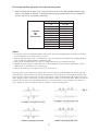
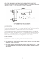
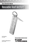
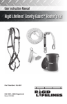
Manual 103-0047
REV. 08/14
Installation, Instruction, Maintenance & Spare Parts Manual for
Rigid Lifelines Fold-Away and Swing Arm Fall Protection Systems
ISO 9001 REGISTERED
© RIGID LIFELINES®
2
TABLE OF CONTENTS
Forward...................................................................................................................... 4
Fall Protection Safety and Considerations...................................................................... 5
Fall Protection Component and System Installation Requirements................................... 6
Installation Instructions............................................................................................... 6
Performance Testing of Fall Protection Components and Systems............................... 6
Usage Notes.......................................................................................................... 7
Installation Procedure............................................................................................. 8
Splices.................................................................................................................. 9
Top and Bottom Wall Brackets....................................................................................10
Fold-Away Fall Protection System Charts
Single Person / Single Track............................................................................. 11-12
Two Person / Single Track.................................................................................13-14
Two Person / Dual Track................................................................................... 15-16
Swing Arm Fall Protection System Charts
Single Person / Single Track.................................................................................. 17
Two Person / Dual Track........................................................................................ 17
Fall Protection Safety and Maintenance Instructions............................................... 18-20
Fold-Away and Swing Arm Parts Lists
Standard Boom to Track Connection (Fold-Away Only)............................................. 21
300 Swing Arm Only (Single Track)........................................................................22
300 Swing Arm Only (Dual Track)..........................................................................23
Motorization Option.............................................................................................. 24
Motorized Single Track..........................................................................................25
Boom Lock Option................................................................................................26
Mechanical Stops................................................................................................. 27
Adjustable Boom Lock.......................................................................................... 28
Manual Extend / Retract Rope............................................................................... 29
Annual Systems Inspection Checklist.......................................................................... 30
Annual Fold-Away Systems Inspection Checklist...........................................................31
Rigid Lifelines Warranty and Service Policy..................................................................32
3
FORWARD
This manual contains important information to help you install, operate, maintain, and
service your new fall protection fold-away or swing arm jib system. We recommend that you
study its contents thoroughly before putting the system into use. By practicing the
recommended maintenance, with proper installation, and application of correct operating
procedures, you will be assured maximum service from your fall protection system.
The systems described in this manual are intended for indoor service. Systems used for outdoor
service require special consideration.
INSTALLATION:
Before attempting to install your new system, the following items must be understood...
1. It is the customer’s responsibility to ensure that building columns or walls are adequate
to support the system.
2. Systems should not be hung from an existing building structure without first consulting
a qualified architect or engineer for the purpose of determining the structure’s
adequacy.
! WARNING
r
NOTE: DO NOT MOUNT THE SYSTEM TO ANY STRUCTURE UNLESS YOU ARE SURE
THE STRUCTURE CAN SAFELY SUPPORT THE LOADS IMPOSED UPON THE
STRUCTURE. FAILURE TO CHECK THIS ITEM CAN RESULT IN SEVERE BODILY
INJURY OR DEATH.
*The systems are not designed for lateral loading of boom, but rather vertical only.
3. The installer is responsible for supplying the correct size, length, number, and type of
bolts required to attach the system brackets to the structure. Rigid Lifelines
recommends that the bolts be ASTM A325 grade.
4. In the design of Rigid Lifelines fall protection fold-away and swing arm jib
systems, there is a certain amount of deflection that will occure due to the self weights
of the system. There is also additional deflection due to the structure it is mounted to,
such as the buidling columns, in which the installer or customer is responsible for since
it can vary. These factors are combined with additional deflection caused if a man or
men actually fall and are hanging from the structure. If the deflection is too great, there
is the less desired possibility that after a fall, a man could begin to slowly slide along
the track. Although Rigid Lifelines does design to accommodate for deflection, Rigid
Lifelines also recommends the installer adjust the boom tip equal to an elevation of
L/300 inches ABOVE the boom center (a point on the boom closest to the wall). Shims
can be used between the “bracket to wall connection” to make this adjustment. For
example, L/300 for a 20’ span is equal to (12*20)/300=0.80”, or approximately 3/4”.
This would mean that when installation is complete, the boom tip in this example would
be approximately 3/4” higher than the inner most part of the boom.
4
FALL PROTECTION SAFETY AND CONSIDERATIONS
Fall Protection Safety
1. Remove systems and components from service IMMEDIATELY if they have been
subjected to fall impact until inspected by a competent person and deemed undamaged
and suitable for use.
2. Promptly rescue employees in the event of a fall, or assure that they are able to rescue
themselves. (Rigid Lifelines sells a self-rescue trolley to assist in self-rescue.)
3. Inspect systems prior to each use for wear, damage, and other deterioration; and remove
defective components.
4. Do NOT attach fall arrest systems to guard rail systems or hoists.
5. Do NOT attach fall arrest systems to crane bridges unless specifically designed for such
use by a competent engineer.
6. Every fall arrest system should have a rescue plan to recover fallen workers. If the same
fall arrest system will be used to recover a fallen worker, a two man system must be
specified.
Fall Protection Considerations
Anyone working in general industry over a height of 4 ft. or more above a lower level with
an unprotected side or edge shall be protected from falling.
Anchorages used for attachment of personal fall arrest equipment shall be certified for the
applied forces by others.
Note: Consult factory for custom design if maximum arresting force exceeds 900 lb.
If the system is to be used by an employee having a combined person and tool weight of
more than 310 pounds, then the system must be appropriately modified.
Check bolts annually for tightness.
5
FALL PROTECTION COMPONENT AND
SYSTEM INSTALLATION REQUIREMENTS
Engineered fall protection components and standard systems displayed in Rigid Lifelines sales
literature meet or exceed all regulations as defined by ANSI Z359, OSHA 1910.66 and OSHA
1926.502 for engineered components.
Rigid Lifelines fall arrest components and systems must be employed and maintained in
accordance with all ANSI and OSHA regulations.
INSTALLATION INSTRUCTIONS
Install components as defined in this manual and in accordance with ANSI and OSHA regulations.
If the system is a standard engineered fall protection system, install the system(s) as defined on the
provided assembly drawings.
If the system has been custom engineered as custom system by Rigid Lifelines, install the
system(s) as defined on the provided custom assembly drawing.
NOTE: Rigid Lifelines fall protection components are similar to crane designs, but may never be used as a
crane.
! WARNING
r
Never use a Rigid Lifelines fall protection component or system as a crane or
to lift objects, unless specifically engineered by Rigid Lifelines to do so.
PERFORMANCE TESTING OF
FALL PROTECTION COMPONENTS AND SYSTEMS
Rigid Lifelines recommends following the ANSI requirements for dynamic performance testing of all
Rigid Lifelines fall protection components and systems. The dynamic performance test, as defined
by ANSI Z359.1-1992 (R1999) consists of a 220 lb test weight dropped for a total 6-foot free fall
before a 900 lb MAF (maximum arresting force) 6’ long “ripstitch” energy absorbing lanyard
engages to decelerate the load. A two-man system will use two separate weights (using one 900
MAF lanyard per weight), a three-man system will use three separate weights, and so on. ANSI
standards are available at www.ansi.org
6
USAGE NOTES
1.
2.
3.
4.
5.
6.
7.
8.
9.
10.
11.
12.
13.
14.
15.
16.
17.
18.
19.
20.
21.
Read, understand and follow instructions of all component manuals and warnings
before use.
Follow all current requirements of ANSI Z359.
The following requirements do not preempt any current OSHA, Canadian, or ANSI
Z359 fall protection requirements.
Always perform a hazard analysis before use that will indentify impact hazards,
swing hazards, or any other hazards that may exist. Address and correct all hazards
before use.
Inspect system before use, check for bent, broken, or missing components.
Inspect thoroughly by competent person after each fall.
Inspect annually by competent person.
Never load track at an angle greater than 30º from vertical.
Never use system with the attachment point below the D-ring of the harness.
Never use with scaffolding.
Always have a written rescue plan that defines who will rescue and what equipment
will be used.
Never use without a worker monitor (buddy system).
If the same fall arrest system will be used to recover a fallen worker a minimum of a
two man system must be specified.
Engineering of any attachment points by others. See the thrust and pull forces
defined in this literature.
Only the following self retracting lanyard (SRL) design is acceptable for use on
SPANCO Rigid Lifelines fall protection systems:
1) 900LB MAF
2) 4.5FT per second lock up speed
3) Disk or drum braking mechanism
4) Wire rope SRL for outdoor use
5) Fabric lanyard SRL for indoor use only
Tearable lanyard, rip stitch packs, or stretchable energy absorbers are not acceptable.
Choose the shortest length self retracting lanyard (SRL) available that will allow the
worker to peform his/her job function. This will reduce total fall distance and thereby
limit any possible injury during a fall. Short cable lengths will reduce the amount of
“cable cinching” on the internal SRL pulley, thereby reducing fall distance.
Only an ANSI full body fall protection harness is acceptable for use on Rigid
Lifelines systems.
Never use body belts on Rigid Lifelines fall protection systems.
If a jib boom is provided, never apply a lateral load at the boom tip.
Per OSHA and ANSI, a competent person must provide proper user training
before use.
Never deviate from the above unless you have written permission and authorizaiton
from Rigid Lifelines.
7
After reading all the information prior, you may begin the installation procedure. The following is for
either a swing arm jib or fold-away system.
NOTE: For installing a fold away system, first install the boom arms as described below (before installing
the track)
1. Be sure of proper span clearance when the system folds outward (this should have already been
determined).
2. Be sure that the top of the system will have adequate ceiling clearance before proceeding (this
should have already been determined).
3. Hold the top wall bracket against the supporting column in its proper location with a C-clamp or
other supporting method.
4. Establish the correct distance from the top wall bracket to the bottom wall bracket. Refer to the
charts for bracket centers. Hold the bottom wall bracket against the supporting column with a
C-clamp or other supporting method.
5. Use a plumb bob to check the alignment of the bottom bracket with the top bracket in two
planes. The alignment must be within 1/16 inches from top to bottom.
6. Using the wall brackets as a template, mark the established hole locations.
7. Drill the holes in the column for the wall brackets.
8. Mount the wall brackets and their shims (if used) to the column with bolts supplied by the
installer. If “bolt on” rotation stop plates are to be installed, this step is the best time to do that
(see page 26). Care should be taken to insure all bolts are properly tightened.
9. Lift the assembly with its bearings attached with a lift truck, or other means, into place.
Insert the hex head bolt through the bracket. Insure the thrust plate is properly located at the
bottom of each bearing. Install the lock washer and hex nut onto the bolts. Tighten the nut to
the torque listed:
PIVOT
BOLT
TORQUE
ONLY
PIVOT BRACKET STYLE
BOLT SIZE
TORQUE ON NUT
1T
1”
40 FT-lbs.
2T
1 1/4”
75 FT-lbs.
8
The following remaining step applies only to the fold-away systems:
1. After installing the jib boom arms, hang the pieces of track with the provided hardware (see
sketch) and torque as required. The pivoting bolt (rotating eye bolt) with the nut, composite
washer, and roll pin are already assembled.
STRUCTURAL
BOLT
ONLY
(NOT PIVOT BOLTS)
FASTENER SIZE
TORQUE FT. LBS.
1/4”
5/16”
3/8”
7/16”
1/2”
9/16”
5/8”
3/4”
7/8”
1”
1 1/4”
10 FT. LBS.
19 FT. LBS.
33 FT. LBS.
54 FT. LBS.
78 FT. LBS.
114 FT. LBS.
154 FT. LBS.
257 FT. LBS.
341 FT. LBS.
514 FT. LBS.
803 FT. LBS.
Splices
1. Track splice joints are supplied complete with vertical and horizontal adjustment screws which facilitate
precise alignment of the track sections at a joint.
2. When positioning splice joints it is important to insure that they are placed within the allowable distance
from an adjacent support bracket for maximum loads.
3. Splice joints should be within 18” max, of a support bracket unless otherwise specified.
4. Welded joints are possible, however they are not recommended as they inhibit the adjustments, future
modification, or dismantling of a system angles.
5. Splices are used to join the upper chords of the truss section.
The track splice joint is made from a sleeve with a total of eight set screws threaded into the top and both
sides. Slide the sleeve over the end of the first runway track, then butt the second runway track against the
first. Center the sleeve over the joint. The two center top set screws should be tightened slightly to push the
tracks against the base of the sleeve so that the two bottom surfaces of the track are even. Adjust the side set
screws so that the track slots are aligned and there is a smooth transition from one track to the other, see
Fig. 1. Tighten all top set screws then side set screws for correct track alignment.
(Fig. 1)
9
NOTE: SYSTEMS SHOULD NEVER BE HUNG FROM ANY EXISTING BUILDING STRUCTURE, WITHOUT FIRST
CONSULTING AN ARCHITECT OR STRUCTURAL ENGINEER. THE RESPONSIBILITY IN DETERMINING IF THE EXISTING
STRUCTURE OR SUPPORT TO BE USED IS ADQUATE, RESTS ENTIRELY ON THE CUSTOMER.
R2 + R4 = 100% of vertical load.
Also, either R2 or R4 can = 100% of vertical load.
TOP AND BOTTOM WALL BRACKETS
BASIC DESCRIPTION:
The top and bottom wall brackets in this case are identical fittings. The fittings are of the
same basic configuration for all models, except for the drilling dimensions.
The fitting consists of a formed channel, a fabricated bracket, two bronze bushings and
bolt to provide rotation. The fabricated bracket is constructed from a steel tube welded to
plating in an “I” arrangement which is then welded to the flange of the mast. The tube
contains two bronze bushings and grease fitting to assure ease of rotation.
DESIGN ADVANTAGES:
A) Pivot bolt is in double shear, which provides for a stronger connection.
B) The bronze bushing and grease fitting provides excellent lubrication and ease of rotation
for long life and low maintenance.
C) The bracket assembly is designed to supply maximum rigidity because of the “I” shape.
This shape also provides sufficient length for a sound connection between the bracket
and the mast.
10
FOLD-AWAY FALL PROTECTION
Dimensions and weights are approximate and may change without notice.
11
FOLD-AWAY FALL PROTECTION
Dimensions and weights are approximate and may change without notice.
12
FOLD-AWAY FALL PROTECTION
Dimensions and weights are approximate and may change without notice.
13
FOLD-AWAY FALL PROTECTION
Dimensions and weights are approximate and may change without notice.
14
FOLD-AWAY FALL PROTECTION
Dimensions and weights are approximate and may change without notice.
15
FOLD-AWAY FALL PROTECTION
Dimensions and weights are approximate and may change without notice.
16
SWING ARM FALL PROTECTION
17
FALL PROTECTION SAFETY AND MAINTENANCE INSTRUCTIONS
All potential users of this equipment and user’s management must read and understand all
instructions fully; failure to do so could result in serious or fatal injury.
The user is ultimately responsible for his or her own safety when using a Rigid Lifelines fall
arrest product. The following safety and maintenance instructions are designed to make
your Rigid Lifelines product as safe as possible. To obtain the utmost level of safety that
this equipment can provide all instructions must be followed thoroughly.
All Rigid Lifelines Fall Arrest systems are designed with a safety factor of two.
Fall Arrest systems are fully engineering systems based on calculations and testing. All
systems are designed to take a maximum arresting force to 900 lbs. per person.
Rigid Lifelines fall arrest systems should be inspected annually and at minimum as
described below. For the highest level of safety, Rigid Lifelines fall arrest systems can be
checked before each use as described below. The user or management should determine
what system will be inspected when, and it is always a good idea to keep an inspection log.
Above all simple common sense must always be used to keep safety first.
Overview
• Inspect and maintain equipment
• Understand the limitations and requirements of the equipment
• Understand the penalties of not following and understanding the instructions
• If any of the below items fail the product is unsafe and must be marked unsafe and the
system’s use must be discontinued until the system is fixed.
Fall Arrest Track (Where Applicable)
•
•
•
•
•
Inspect for loose debris inside track
Check track for cracks, holes, heavy rust, or deterioration
If trussed track, inspect welds for stress cracks or broken welds
Flange thickness should not be worn to less than 90% of original thickness
Flange should not be bent more than 5 degrees below horizontal
Hanger System (Where Applicable)
• Inspect roof beam clamp bolts to see if tightened to 108 FT.lbs.
• See if all adjustment screws are tight and accounted for
• For side support brackets inspect all mounting bolts, nuts and lock washers for proper
installation and tightness
• For drop rod support brackets, inspect for broken welds or stress cracks, inspect
drop rods for being bent along with checking drop rod bolts for tightness and
proper installation
• Inspect all beam clamps for proper installation and if tightened to 108 FT.lbs.
18
End Stop Bumper (Where Applicable)
• Inspect to see if end stop bumper is installed at each end of track
• Inspect rubber for wear
• Check for lock washer and nut and check for tightness
Splices (Where Applicable)
• Check for installation of all alignment bolts and inspect for tightness (on track)
• Inspect the four through bolts and check for 50 FT.lbs on bolt head (on Truss)
• Splices should be installed within 1 foot of hanger
Swivel Eye Trolley (Where Applicable)
• Inspect eye for 360 degree of free rotation
• Check for free movement of trolley rolling back and forth with no binding or hesitation
for wheel and bearing use
Sway Bracing (drop rod systems) (Where Applicable)
• Check for proper tightness
• Check for hanging or broken or frayed cables
• Check all connections for proper installation
End Trucks (Bridge Crane system) (Where Applicable)
• Roll bridge to each end of runway checking smoothness for wheel and bearing use
• Inspect bolts on fixed end truck (one per bridge) to see if all tightened
Wall Brackets (Where Applicable)
•
The sleeve bearings in the brackets are pre-lubricated at the factory. Field lubrication is
required based upon usage of the system. Rigid Lifelines recommends that the bearings
be lubricated at lease once per year. The grease should be lithium soap based grease,
consistency No. NLGI 2.
Training Procedures (strongly encouraged)
•
•
•
•
•
•
Locate all fall hazards and eliminate
Find and reduce free fall distances
Properly fit a harness
Inspect and maintain equipment
Know the limitations of the equipment
Know the consequence of not following safety instructions
19
Emergency Plan
•
Minimum time take should be taken to rescue casualty victim, due to blood restriction
cause from harness.
• Fire department or other means of professional emergency services should be notified
immediately to carry rescue out, due to possible spine injury or possible suspension
trauma injury.
Checklist
• System assembled to Rigid Lifelines instructions and standards?
• Has user been properly trained on equipment?
• Is the system being used within maximum load capacities?
• Has system been checked with Inspection and is maintenance log being filled
out regularly?
FALL ARREST IS NOT DESIGNED FOR NORMAL CRANE USE, ONLY FOR FALL PROTECTION
THE BUYER IS RESPONSIBLE FOR ENSURING CORRECT STRENGTH AND RELIABILITY OF SYSTEM
AND PROPER INSTALLATION ACCORDING TO ALL APPLICABLE FALL ARREST SPECIFICATIONS
ALL RIGID LIFELINES TRACK, TROLLEYS, JIBS, AND HANGERS ARE DESIGNED IN ACCORDANCE
WITH A.N.SI. Spec No. Z359, OSHA 1910.66 and OSHA Std.1926.502
20
STANDARD BOOM TO TRACK CONNECTION (FOLD-AWAY ONLY)
21
300 SWING ARM ONLY (SINGLE TRACK)
22
300 SWING ARM ONLY (DUAL TRACK)
23
MOTORIZATION OPTION
24
MOTORIZED SINGLE TRACK
25
BOOM LOCK OPTION
26
MECHANICAL STOPS
If over-rotation of a fold-away structure is a concern, if included, use the mechanical stops
(see sketch). The Installer’s judgment should be used to determine if required (2 stops may
be supplied). The stops are most effective on a two boom non-motorized system to keep the
system from over rotating. Another reason the installer may desire to use them on a more
than two boom system is to keep the track from hitting the mast. There may be other
concerns the installer should consider, such as facility obstructions, etc. The stop is
normally placed on the folding side of the upper bracket as shown (see sketch). During
system operation, the head of the bolt sticking out will hit a portion of the bracket and thus
limit rotation of the system. Installing the second stop on a different boom could keep the
track from hitting the booms, although this is not required. Again, the installer should use
his/her discretion weather or not the stops are need, as every case is different. The use of a
limit switch, for example, may be all that an installer desires to use. If installing the stops,
to save time, install during structure (boom) installation (see page 8). Note that different
length “bracket to column” bolts may be required (bolts are not included). If retrofitted,
properly secure weight of structure with an overhead hoist or other means before removing
bracket bolts (to help avoid injury).
27
ADJUSTABLE BOOM LOCK
28
MANUAL EXTEND / RETRACT ROPE
For manually operated fold away systems,
attach the end of the track to this end of
the extend/retract rope as shown. Note
that the SRL’s are not to be used to
extend/retract fold away systems.
29
This end of the rope is used to pull on
the system.
Rigid Lifelines Annual Fall Protection Systems
Inspection Checklist
Inspector Name: ___________________ Date: ____________________
System Number: ___________________ Model: ____________________
Inspection Result (3)
Inspection Point
Pass
1)
Check that the beam clamps are installed horizontal within + / - 5 degrees.
2)
Check that endstop bolts are present and have locknuts installed.
3)
Using a torque wrench, check that all bolts are torqued to values shown in manual.
4)
Check that splices, if supplied, are centered on track joints.
5)
Verify that capacity signs are present, attached, and legible.
6)
Verify that the number of trolleys matches the value on the capacity sign.
7)
Verify that the fall arrest system is not being used for material handling.
8)
Check the track for levelness within + / - 1/4” per 20 feet of track.
9)
Check the track flanges. Track flanges cannot be bent downward more than 5 degrees.
10)
Check the track thickness. Track thickness cannot be worn more than 10 percent.
11)
Check all system welds for cracks.
12)
Check system components for corrosion.
13)
Check system components for bent or damaged areas.
14)
Verify trolley can traverse entire length of track without snags.
15)
Check connector trolley for visibly bent eye bolt, broken welds, or excessive wear
or corrosion
16)
Test the operation of the connector trolley eye bolt and verify the eye bolt can
rotate freely.
17)
Test the operation of the connector trolley and verify the wheels rotate freely.
18)
Check system components for loose components.
19)
Check system components for loose or missing fasteners.
20)
Check system support structure for stability.
21)
Verify that any hangar clamps are installed properly and fasteners are torqued to proper
values.
30
Fail
Rigid Lifelines Fold-Away Fall Protection Systems
Inspection Checklist
Inspector Name: ___________________ Date: ____________________
System Number: ___________________ Model: ____________________
Inspection Result (3)
Inspection Point
Pass
1)
Test the operation of the support jibs and verify the jibs and connector pivots
rotate freely.
2)
Check the support jibs for excessive bearing wear.
3)
Check the support jibs for properly installed and tightened pivot bolts.
4)
Check the support jibs for loose or missing fasteners.
5)
Check the jib connector pivots for bent or broken parts, or bent or broken welds.
6)
Check support structure for stability.
* Download and print blank checklists from the Literature link at rigidlifelines.com
31
Fail
Rigid Lifelines
730 Hemlock Road
Suite 104
Morgantown, PA 19543
Toll Free: (844) 467-4443
Local: (610) 286-8030
Fax: (610) 286-6408
RigidLifelines.com
TEN-YEAR EQUIPMENT WARRANTY
Rigid Lifelines warrants the engineered track equipment, wearable end truck wheels, and Anchor Trolley™ wheels and teeth to be free from
defects in material and workmanship for a period of ten (10) years commencing on the date of installation.
TWO-YEAR EQUIPMENT WARRANTY
Rigid Lifelines warrants XSPlatforms Fall Protection components to be free from defects in material and workmanship for a period of two (2)
years commencing from the date of installation.
ONE-YEAR EQUIPMENT WARRANTY
Rigid Lifelines warrants the motorized products and drive components to be free from defects in material and workmanship for a period of one
(1) year, commencing on the date of shipment to the first retail purchaser (“Purchaser”).
Rigid Lifelines warrants all Rigid Lifelines fall protection soft goods, devices, connectors, and accessories to be free from defects in material
and workmanship for a period of one (1) year, commencing on the date of shipment to the first retail purchaser (“Purchaser”).
Rigid Lifelines is dedicated to offering superior service and quality products to all of our customers. If you would like to contact a customer
service representative, please call the following number: 1 (844) 467-4443. We will be happy to assist you in any way that we can.
These warranties do not extend to equipment which has been subject to misuse, use in excess of rated capacity, negligent operation, use
beyond Rigid Lifelines published service factors, improper installation or maintenance, adverse environments, and does not apply to any
equipment which has been repaired or altered without Rigid Lifelines written authorization. This warranty is void for any product that is
designed to deform or absorb energy during a fall event and needs to be replaced after a fall event has occurred.
Written notice of any claimed defect must be given to Rigid Lifelines within thirty (30) days after such defect is discovered. Rigid Lifelines
obligation, and Purchaser’s sole remedy under this warranty is limited to, at Rigid Lifelines discretion, the replacement or repair of the
equipment at Rigid Lifelines factory or at a location approved by Rigid Lifelines. THIS WARRANTY IS EXPRESSLY IN LIEU OF ALL OTHER
WARRANTIES WHATSOEVER WHETHER EXPRESS, IMPLIED, OR STATUTORY. SELLER MAKES NO WARRANTY AS TO THE
MERCHANTABILITY OR FITNESS FOR A PARTICULAR PURPOSE OF THE EQUIPMENT AND MAKES NO OTHER WARRANTY, EITHER
EXPRESS OR IMPLIED.
Rigid Lifelines shall not be liable, under any circumstances, for any indirect, special, or consequential damages including (but not limited to):
lost profits, increased operating costs, or loss of production. This warranty shall not extend to damages including (but not limited to): lost
profits, increased operating costs, or loss of production. This warranty shall not extend to any components or accessories not manufactured by
Rigid Lifelines (example: casters), with the exception of the components, systems, or accessories involved with XSPlatforms, and purchaser’s
remedy for such components and accessories shall be determined by the terms and conditions of any warranty provided by the manufacturer
of such components and accessories.
SERVICE POLICY
1.
Obtain as much information as possible concerning the problem through personal observation by yourself or other authorized personnel
familiar with the job and equipment: include model, serial and/or part numbers, voltages, speeds and any other special identifying
features. Be prepared to discuss the situation in detail.
2.
All authorized labor charges will be based on straight time. Hourly rates, estimated man hours, and not to exceed total dollar amount
required for corrections are to be agreed upon before authorization is given. There will be no allowances for overtime except in dire
emergencies and then only with prior approval.
3.
A verbal agreement may be reached immediately on both the method of correction and the approximate cost. A warranty authorization
number will be assigned for the specific incident. A confirming written authorization will be forwarded to the distributor.
4.
The distributor must send an itemized invoice, showing our release number or invoice number and warranty authorization number after
authorized corrections have been made. A credit memo will be issued by accounting after the invoice has been received and approved.
Warranty charges ARE NOT to be deducted from outstanding open account invoices under any circumstances.
5.
Any field corrections made prior to an authorization by Rigid Lifelines will not be accepted as a warranty charge or the responsibility
of Rigid Lifelines. Any modification to the equipment made without the prior approval of the seller will void all warranties. A verbal
authorization for modification may be obtained, in which event a warranty authorization number will be assigned for the specific
modification. A confirming written authorization will be forwarded to the distributor.
©2014. All rights reserved. All specifications and product designs subject to change without notice.
All trademarks are the sole property of their respective owners. RLL-FASAFPSUIMV1
32