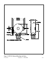
1
SN
FTC 121-1 System Controller
User Manual
Flash Technology Corporation of America®, 332 Nichol Mill Lane, Franklin, TN, 37067
(615) 261-2000
Front Matter
Abstract
This manual describes the Operation, Installation, and Maintenance, of the FTC 121-1 System Controller.
Copyright
Copyright © 1997 Flash Technology Corporation of America®, Franklin, TN, 37067, U.S.A.
All rights reserved. Reproduction or use of any portion of this manual is prohibited without express written permission from Flash Technology Corporation of America and/or its licenser.
Trademark Acknowledgments
Flash Technology Corporation of America® is a registered trademark name. ElectroFlash™ is a trademark of
Flash Technology Corporation of America.
All trademarks and product names mentioned are properties of their respective companies, and are recognized
and acknowledged as such by Flash Technology Corporation of America.
Applicable Specification
This equipment meets or exceeds requirements for controlling FAA Type L-856 high intensity white obstruction
lights, L-865 medium intensity obstruction lights, and L-864 red obstruction lights described in Advisory Circular 150/5345-43E.
Disclaimer
While every effort has been made to ensure that the information in this manual is complete, accurate and
up-to-date, Flash Technology Corporation of America assumes no liability for damages resulting from any errors
or omissions in this manual, or from the use of the information contained herein. Flash Technology Corporation
of America reserves the right to revise this manual without obligation to notify any person or organization of the
revision.
In no event will Flash Technology Corporation of America be liable for direct, indirect, special, incidental, or consequential damages arising out of the use of or the inability to use this manual.
Warranty
All components are fully warranted, under normal operating conditions, for two years.
Replacement Parts
The use of parts not manufactured or supplied by FTCA or unauthorized modification of this equipment voids the warranty and could invalidate the assurance of complying with FAA requirements for
controlling high and medium intensity lights as published in Advisory Circular 150/5345-43.
Pub. No. 0594-1211-0003
ii
Revision 4 — 12-16-1998
FTC 121-1
PERSONNEL HAZARD WARNING
Dangerous Voltages
Dangerous line voltages reside in certain locations in this equipment. Although FTCA
has incorporated every practical safety precaution, exercise extreme caution at all
times when you expose circuits and components, and when you operate, maintain, or
service this equipment.
Avoid Touching Live Circuits
Avoid touching any component or any part of the circuitry while the equipment is
operating. Do not change components or make adjustments inside the equipment
with power on.
FTC 121-1
Revision 4 — 12-16-1998
iii
Table of Contents
Section . . . . . . . . . . . . . . . . . . . . . . . . . . . . . . . . . . . . . . . . . . . . . . . . . . . . . . . . . . . . .
Page
Front Matter . . . . . . . . . . . . . . . . . . . . . . . . . . . . . . . . . . . . . . . . . . . . . . . . . . . . . . . . . . . . . . . ii
Abstract . . . . . . . . . . . . . . . . . . . . . . . . . . . . . . . . . . . . . . . . . . . . . . . . . . . . . . . . . . . . . . . . ii
Copyright . . . . . . . . . . . . . . . . . . . . . . . . . . . . . . . . . . . . . . . . . . . . . . . . . . . . . . . . . . . . . . . ii
Trademark Acknowledgments . . . . . . . . . . . . . . . . . . . . . . . . . . . . . . . . . . . . . . . . . . . . . . ii
Applicable Specification . . . . . . . . . . . . . . . . . . . . . . . . . . . . . . . . . . . . . . . . . . . . . . . . . . . ii
Disclaimer . . . . . . . . . . . . . . . . . . . . . . . . . . . . . . . . . . . . . . . . . . . . . . . . . . . . . . . . . . . . . . ii
Warranty . . . . . . . . . . . . . . . . . . . . . . . . . . . . . . . . . . . . . . . . . . . . . . . . . . . . . . . . . . . . . . . ii
Replacement Parts . . . . . . . . . . . . . . . . . . . . . . . . . . . . . . . . . . . . . . . . . . . . . . . . . . . . . . . ii
Table of Contents . . . . . . . . . . . . . . . . . . . . . . . . . . . . . . . . . . . . . . . . . . . . . . . . . . . . . . . . . . . iv
List of Tables . . . . . . . . . . . . . . . . . . . . . . . . . . . . . . . . . . . . . . . . . . . . . . . . . . . . . . . . . . . . . . vii
List of Figures . . . . . . . . . . . . . . . . . . . . . . . . . . . . . . . . . . . . . . . . . . . . . . . . . . . . . . . . . . . . . vii
Section 1 — Introduction . . . . . . . . . . . . . . . . . . . . . . . . . . . . . . . . . . . . . . . . . . . .
System . . . . . . . . . . . . . . . . . . . . . . . . . . . . . . . . . . . . . . . . . . . . . . . . . . . . . . . . . . . . . .
Remote Monitoring and Control Option: Eagle Software . . . . . . . . . . . . . . . . . . . . . .
1-1
1-1
1-1
Section 2 — Outline, Mounting, and Installation . . . . . . . . . . . . . . . . . . . . . . .
Unpacking . . . . . . . . . . . . . . . . . . . . . . . . . . . . . . . . . . . . . . . . . . . . . . . . . . . . . . . .
Tools . . . . . . . . . . . . . . . . . . . . . . . . . . . . . . . . . . . . . . . . . . . . . . . . . . . . . . . . . . . . .
Access . . . . . . . . . . . . . . . . . . . . . . . . . . . . . . . . . . . . . . . . . . . . . . . . . . . . . . . . . . . .
FTC 121-1R Controller . . . . . . . . . . . . . . . . . . . . . . . . . . . . . . . . . . . . . . . . . . .
FTC 121-1W Controller . . . . . . . . . . . . . . . . . . . . . . . . . . . . . . . . . . . . . . . . . . .
Mounting . . . . . . . . . . . . . . . . . . . . . . . . . . . . . . . . . . . . . . . . . . . . . . . . . . . . . . . . . . . .
FTC 121-1R Controller . . . . . . . . . . . . . . . . . . . . . . . . . . . . . . . . . . . . . . . . . . . . . .
FTC 121-1W Controller . . . . . . . . . . . . . . . . . . . . . . . . . . . . . . . . . . . . . . . . . . . . . .
PEC 510 Photocell . . . . . . . . . . . . . . . . . . . . . . . . . . . . . . . . . . . . . . . . . . . . . . . . . .
Wiring . . . . . . . . . . . . . . . . . . . . . . . . . . . . . . . . . . . . . . . . . . . . . . . . . . . . . . . . . . . . . .
All installation wiring should have an insulation rating of 600 volts. . . . . . . . . .
External Connections . . . . . . . . . . . . . . . . . . . . . . . . . . . . . . . . . . . . . . . . . . . . . . . . . .
Installation Checklist . . . . . . . . . . . . . . . . . . . . . . . . . . . . . . . . . . . . . . . . . . . . . . . . . .
2-1
2-1
2-1
2-1
2-1
2-1
2-1
2-1
2-1
2-1
2-2
2-2
2-2
2-2
Section 3 — Operation . . . . . . . . . . . . . . . . . . . . . . . . . . . . . . . . . . . . . . . . . . . . . .
Menu Functions . . . . . . . . . . . . . . . . . . . . . . . . . . . . . . . . . . . . . . . . . . . . . . . . . . . . . . .
View Menu . . . . . . . . . . . . . . . . . . . . . . . . . . . . . . . . . . . . . . . . . . . . . . . . . . . . . . . .
User Menu . . . . . . . . . . . . . . . . . . . . . . . . . . . . . . . . . . . . . . . . . . . . . . . . . . . . . . . .
Directory of Available Screens . . . . . . . . . . . . . . . . . . . . . . . . . . . . . . . . . . . . . . . . . . .
Operation Panel . . . . . . . . . . . . . . . . . . . . . . . . . . . . . . . . . . . . . . . . . . . . . . . . . . . . . . .
LED Indicators and Front Panel Buttons . . . . . . . . . . . . . . . . . . . . . . . . . . . . . . . . . .
Menus and Screens . . . . . . . . . . . . . . . . . . . . . . . . . . . . . . . . . . . . . . . . . . . . . . . . . . . .
Cursor . . . . . . . . . . . . . . . . . . . . . . . . . . . . . . . . . . . . . . . . . . . . . . . . . . . . . . . . . . .
Screen Saver . . . . . . . . . . . . . . . . . . . . . . . . . . . . . . . . . . . . . . . . . . . . . . . . . . . . . .
Opening Screens . . . . . . . . . . . . . . . . . . . . . . . . . . . . . . . . . . . . . . . . . . . . . . . . . . . . . .
New Starting Screen . . . . . . . . . . . . . . . . . . . . . . . . . . . . . . . . . . . . . . . . . . . . . . . .
Alarms . . . . . . . . . . . . . . . . . . . . . . . . . . . . . . . . . . . . . . . . . . . . . . . . . . . . . . . .
No Unacknowledged Alarms or Status Codes are Present . . . . . . . . . . . . . . . . . .
No Alarms Present Screen . . . . . . . . . . . . . . . . . . . . . . . . . . . . . . . . . . . . . . . .
View and User Menus . . . . . . . . . . . . . . . . . . . . . . . . . . . . . . . . . . . . . . . . . . . . . . . . . .
3-1
3-1
3-1
3-1
3-2
3-4
3-5
3-5
3-6
3-6
3-6
3-6
3-6
3-6
3-6
3-6
iv
Revision 4 — 12-16-1998
FTC 121-1
Table of Contents (cont’d)
Section . . . . . . . . . . . . . . . . . . . . . . . . . . . . . . . . . . . . . . . . . . . . . . . . . . . . . . . . . . . . .
Page
Section 4 Operation — View Menu . . . . . . . . . . . . . . . . . . . . . . . . . . . . . . . . . . . .
View Menu . . . . . . . . . . . . . . . . . . . . . . . . . . . . . . . . . . . . . . . . . . . . . . . . . . . . . . . . . . .
Front Panel Button Functions . . . . . . . . . . . . . . . . . . . . . . . . . . . . . . . . . . . . . . . . . . .
Handling Alarms . . . . . . . . . . . . . . . . . . . . . . . . . . . . . . . . . . . . . . . . . . . . . . . . . . . . . .
Acknowledge or Reset an Alarm . . . . . . . . . . . . . . . . . . . . . . . . . . . . . . . . . . . . . . .
Remote Notification of Alarms . . . . . . . . . . . . . . . . . . . . . . . . . . . . . . . . . . . . . . . .
Alarm Displays . . . . . . . . . . . . . . . . . . . . . . . . . . . . . . . . . . . . . . . . . . . . . . . . . . . .
Alarm Screens . . . . . . . . . . . . . . . . . . . . . . . . . . . . . . . . . . . . . . . . . . . . . . . . . .
Unacknowledged System Alarm Screen . . . . . . . . . . . . . . . . . . . . . . . . . . . . . . . . .
Alarm Conditions . . . . . . . . . . . . . . . . . . . . . . . . . . . . . . . . . . . . . . . . . . . . . . . .
Specific Beacon Alarm . . . . . . . . . . . . . . . . . . . . . . . . . . . . . . . . . . . . . . . . . . . .
Alarm Display Selection Screen . . . . . . . . . . . . . . . . . . . . . . . . . . . . . . . . . . . .
Unacknowledged System Alarms Present Screen . . . . . . . . . . . . . . . . . . . . . .
Alarm to be Acknowledged Screen . . . . . . . . . . . . . . . . . . . . . . . . . . . . . . . . . .
Alarm Reset Screen . . . . . . . . . . . . . . . . . . . . . . . . . . . . . . . . . . . . . . . . . . . . . .
Ensure Alarm Reset Screen . . . . . . . . . . . . . . . . . . . . . . . . . . . . . . . . . . . . . . .
Alarm to be Reset Screen . . . . . . . . . . . . . . . . . . . . . . . . . . . . . . . . . . . . . . . . .
Alarm is Reset Screen . . . . . . . . . . . . . . . . . . . . . . . . . . . . . . . . . . . . . . . . . . . .
Graphic Display . . . . . . . . . . . . . . . . . . . . . . . . . . . . . . . . . . . . . . . . . . . . . . . . . . . . . . .
Graphic Display Screen . . . . . . . . . . . . . . . . . . . . . . . . . . . . . . . . . . . . . . . . . . . . . .
Graphic Display Selection . . . . . . . . . . . . . . . . . . . . . . . . . . . . . . . . . . . . . . . . .
Graphic Display Screen . . . . . . . . . . . . . . . . . . . . . . . . . . . . . . . . . . . . . . . . . . .
Manual Intensity Select . . . . . . . . . . . . . . . . . . . . . . . . . . . . . . . . . . . . . . . . . . . . . . . .
Manual Intensity Selection . . . . . . . . . . . . . . . . . . . . . . . . . . . . . . . . . . . . . . . .
Intensity Select Screen . . . . . . . . . . . . . . . . . . . . . . . . . . . . . . . . . . . . . . . . . . .
Display Brightness . . . . . . . . . . . . . . . . . . . . . . . . . . . . . . . . . . . . . . . . . . . . . . . . . . . .
Display Brightness Selection . . . . . . . . . . . . . . . . . . . . . . . . . . . . . . . . . . . . . .
Display Brightness Screen . . . . . . . . . . . . . . . . . . . . . . . . . . . . . . . . . . . . . . . .
Date/Time Display . . . . . . . . . . . . . . . . . . . . . . . . . . . . . . . . . . . . . . . . . . . . . . . . . . . . .
Date/Time Display Selection . . . . . . . . . . . . . . . . . . . . . . . . . . . . . . . . . . . . . . .
Date/Time Display Screen . . . . . . . . . . . . . . . . . . . . . . . . . . . . . . . . . . . . . . . . .
Intensity Change Times . . . . . . . . . . . . . . . . . . . . . . . . . . . . . . . . . . . . . . . . . . . . . . . .
Intensity Change Times Selection . . . . . . . . . . . . . . . . . . . . . . . . . . . . . . . . . .
Intensity Change Times Display Screen . . . . . . . . . . . . . . . . . . . . . . . . . . . . .
General Information . . . . . . . . . . . . . . . . . . . . . . . . . . . . . . . . . . . . . . . . . . . . . . . . . . .
General Information Selection . . . . . . . . . . . . . . . . . . . . . . . . . . . . . . . . . . . . .
General Information Screen . . . . . . . . . . . . . . . . . . . . . . . . . . . . . . . . . . . . . . .
Communications Status . . . . . . . . . . . . . . . . . . . . . . . . . . . . . . . . . . . . . . . . . . . . . . . .
Communications Status Screen—No Problems . . . . . . . . . . . . . . . . . . . . . . . .
Communications Status Screen—Problems . . . . . . . . . . . . . . . . . . . . . . . . . . .
User Menu . . . . . . . . . . . . . . . . . . . . . . . . . . . . . . . . . . . . . . . . . . . . . . . . . . . . . . . . . . .
4-1
4-1
4-1
4-2
4-2
4-2
4-2
4-2
4-2
4-3
4-3
4-3
4-4
4-4
4-4
4-5
4-5
4-5
4-6
4-6
4-6
4-6
4-6
4-6
4-7
4-7
4-7
4-7
4-7
4-7
4-7
4-8
4-8
4-8
4-9
4-9
4-9
4-9
4-9
4-10
4-10
Section 5 — Operation; User Menu . . . . . . . . . . . . . . . . . . . . . . . . . . . . . . . . . . . .
User Menu . . . . . . . . . . . . . . . . . . . . . . . . . . . . . . . . . . . . . . . . . . . . . . . . . . . . . . . . . . .
Accessing the User Menu (...more...) . . . . . . . . . . . . . . . . . . . . . . . . . . . . . . . . . . . . . .
Password Selection . . . . . . . . . . . . . . . . . . . . . . . . . . . . . . . . . . . . . . . . . . . . . . . . .
5-1
5-1
5-1
5-1
FTC 121-1
Revision 4 — 12-16-1998
v
Table of Contents (cont’d)
Section . . . . . . . . . . . . . . . . . . . . . . . . . . . . . . . . . . . . . . . . . . . . . . . . . . . . . . . . . . . . .
Enter Password Screen . . . . . . . . . . . . . . . . . . . . . . . . . . . . . . . . . . . . . . . . . . . . . .
Incorrect Password Screen . . . . . . . . . . . . . . . . . . . . . . . . . . . . . . . . . . . . . . . . . . .
User Menu Selections . . . . . . . . . . . . . . . . . . . . . . . . . . . . . . . . . . . . . . . . . . . . . . .
Diagnostics . . . . . . . . . . . . . . . . . . . . . . . . . . . . . . . . . . . . . . . . . . . . . . . . . . . . . . . . . .
Diagnostics Screens . . . . . . . . . . . . . . . . . . . . . . . . . . . . . . . . . . . . . . . . . . . . . . . . . . . .
Diagnostics Selection . . . . . . . . . . . . . . . . . . . . . . . . . . . . . . . . . . . . . . . . . . . . . . .
Total Flashes Screen . . . . . . . . . . . . . . . . . . . . . . . . . . . . . . . . . . . . . . . . . . . . . . . .
Day Flashes Screen . . . . . . . . . . . . . . . . . . . . . . . . . . . . . . . . . . . . . . . . . . . . . . . . .
Twi Flashes Screen . . . . . . . . . . . . . . . . . . . . . . . . . . . . . . . . . . . . . . . . . . . . . . . . .
Nite Flashes Screen . . . . . . . . . . . . . . . . . . . . . . . . . . . . . . . . . . . . . . . . . . . . . . . . .
Red Flashes Screen . . . . . . . . . . . . . . . . . . . . . . . . . . . . . . . . . . . . . . . . . . . . . . . . .
Internal Temp Screen . . . . . . . . . . . . . . . . . . . . . . . . . . . . . . . . . . . . . . . . . . . . . . .
Line Voltage Screen . . . . . . . . . . . . . . . . . . . . . . . . . . . . . . . . . . . . . . . . . . . . . . . .
Trig. Voltage Screen . . . . . . . . . . . . . . . . . . . . . . . . . . . . . . . . . . . . . . . . . . . . . . . .
Bank Voltage Screen . . . . . . . . . . . . . . . . . . . . . . . . . . . . . . . . . . . . . . . . . . . . . . . .
Day Energy Screen . . . . . . . . . . . . . . . . . . . . . . . . . . . . . . . . . . . . . . . . . . . . . . . . .
Twi Energy Screen . . . . . . . . . . . . . . . . . . . . . . . . . . . . . . . . . . . . . . . . . . . . . . . . .
Night Energy Screen . . . . . . . . . . . . . . . . . . . . . . . . . . . . . . . . . . . . . . . . . . . . . . . .
Red Energy Screen . . . . . . . . . . . . . . . . . . . . . . . . . . . . . . . . . . . . . . . . . . . . . . . . .
Mode Flashes Screen . . . . . . . . . . . . . . . . . . . . . . . . . . . . . . . . . . . . . . . . . . . . . . . .
Mode Triggers Screen . . . . . . . . . . . . . . . . . . . . . . . . . . . . . . . . . . . . . . . . . . . . . . .
Marker Voltage Screen . . . . . . . . . . . . . . . . . . . . . . . . . . . . . . . . . . . . . . . . . . . . . .
# Marker Bulbs Screen . . . . . . . . . . . . . . . . . . . . . . . . . . . . . . . . . . . . . . . . . . . . . .
Firmware Number and Version Screen . . . . . . . . . . . . . . . . . . . . . . . . . . . . . . . . .
Set Intensity Change Times . . . . . . . . . . . . . . . . . . . . . . . . . . . . . . . . . . . . . . . . . . . . .
Set Intensity Change Times Selection . . . . . . . . . . . . . . . . . . . . . . . . . . . . . . . . . .
Set Intensity Change Times Screen . . . . . . . . . . . . . . . . . . . . . . . . . . . . . . . . . . . .
Alarm and Status Code Phone Numbers . . . . . . . . . . . . . . . . . . . . . . . . . . . . . . . . . . .
Alarm Call Out Phone Numbers Selection . . . . . . . . . . . . . . . . . . . . . . . . . . . . . .
Alarm Call Out Phone Numbers Screen . . . . . . . . . . . . . . . . . . . . . . . . . . . . . . . .
Status Call Out Phone Number Selection . . . . . . . . . . . . . . . . . . . . . . . . . . . . . . .
Status Call Out Phone Numbers Screen . . . . . . . . . . . . . . . . . . . . . . . . . . . . . . . .
Install PEC . . . . . . . . . . . . . . . . . . . . . . . . . . . . . . . . . . . . . . . . . . . . . . . . . . . . . . . . . .
Install PEC Selection . . . . . . . . . . . . . . . . . . . . . . . . . . . . . . . . . . . . . . . . . . . . . . .
Install PEC Screen . . . . . . . . . . . . . . . . . . . . . . . . . . . . . . . . . . . . . . . . . . . . . . . . .
Set Tower Name . . . . . . . . . . . . . . . . . . . . . . . . . . . . . . . . . . . . . . . . . . . . . . . . . . . . . .
Set Tower Name Selection . . . . . . . . . . . . . . . . . . . . . . . . . . . . . . . . . . . . . . . . . . .
Set Tower Name Screen . . . . . . . . . . . . . . . . . . . . . . . . . . . . . . . . . . . . . . . . . . . . .
Change Password . . . . . . . . . . . . . . . . . . . . . . . . . . . . . . . . . . . . . . . . . . . . . . . . . . . . .
Change Password Selection . . . . . . . . . . . . . . . . . . . . . . . . . . . . . . . . . . . . . . . . . .
Change Password Type Screen . . . . . . . . . . . . . . . . . . . . . . . . . . . . . . . . . . . . . . . .
Change Password Screen . . . . . . . . . . . . . . . . . . . . . . . . . . . . . . . . . . . . . . . . . . . .
Set Number of Rings . . . . . . . . . . . . . . . . . . . . . . . . . . . . . . . . . . . . . . . . . . . . . . . . . . .
Set Number of Rings Selection . . . . . . . . . . . . . . . . . . . . . . . . . . . . . . . . . . . . . . . .
Set Number of Rings Screen . . . . . . . . . . . . . . . . . . . . . . . . . . . . . . . . . . . . . . . . . .
Construction Mode . . . . . . . . . . . . . . . . . . . . . . . . . . . . . . . . . . . . . . . . . . . . . . . . . . . .
Set Construction Mode Selection . . . . . . . . . . . . . . . . . . . . . . . . . . . . . . . . . . . . . .
vi
Revision 4 — 12-16-1998
Page
5-1
5-2
5-2
5-3
5-5
5-5
5-5
5-5
5-6
5-6
5-6
5-6
5-7
5-7
5-7
5-8
5-8
5-8
5-9
5-9
5-9
5-9
5-10
5-10
5-10
5-11
5-11
5-11
5-11
5-11
5-12
5-12
5-12
5-13
5-13
5-13
5-13
5-13
5-13
5-14
5-14
5-14
5-15
5-15
5-15
5-15
5-15
FTC 121-1
Table of Contents (cont’d)
Section . . . . . . . . . . . . . . . . . . . . . . . . . . . . . . . . . . . . . . . . . . . . . . . . . . . . . . . . . . . . .
Construction Mode Screen . . . . . . . . . . . . . . . . . . . . . . . . . . . . . . . . . . . . . . . . . . .
Logoff . . . . . . . . . . . . . . . . . . . . . . . . . . . . . . . . . . . . . . . . . . . . . . . . . . . . . . . . . . . . . . .
Logoff Screen . . . . . . . . . . . . . . . . . . . . . . . . . . . . . . . . . . . . . . . . . . . . . . . . . . .
Page
5-15
5-16
5-16
Section 6 — Replaceable and Spare Parts . . . . . . . . . . . . . . . . . . . . . . . . . . . . . .
Customer Service . . . . . . . . . . . . . . . . . . . . . . . . . . . . . . . . . . . . . . . . . . . . . . . . . . . . . .
Ordering Parts . . . . . . . . . . . . . . . . . . . . . . . . . . . . . . . . . . . . . . . . . . . . . . . . . . . . . . . .
Controller Parts . . . . . . . . . . . . . . . . . . . . . . . . . . . . . . . . . . . . . . . . . . . . . . . . . . . . . . .
Photocell Part . . . . . . . . . . . . . . . . . . . . . . . . . . . . . . . . . . . . . . . . . . . . . . . . . . . . . . . .
6-1
6-1
6-1
6-1
6-1
Index . . . . . . . . . . . . . . . . . . . . . . . . . . . . . . . . . . . . . . . . . . . . . . . . . . . . . . . . . . . . . . . .
I-1
List of Tables
Table . . . . . . . . . . . . . . . . . . . . . . . . . . . . . . . . . . . . . . . . . . . . . . . . . . . . . . . . . . . . . . .
3-1 Sequential Directory of View and User Screens . . . . . . . . . . . . . . . . . . . . . . . . . .
3-2 LED Indicators . . . . . . . . . . . . . . . . . . . . . . . . . . . . . . . . . . . . . . . . . . . . . . . . . . . .
3-3 Front Panel Button Functions . . . . . . . . . . . . . . . . . . . . . . . . . . . . . . . . . . . . . . . .
6-1 Controller Replaceable Parts . . . . . . . . . . . . . . . . . . . . . . . . . . . . . . . . . . . . . . . . .
Page
3-2
3-5
3-5
6-1
List of Figures
Figure . . . . . . . . . . . . . . . . . . . . . . . . . . . . . . . . . . . . . . . . . . . . . . . . . . . . . . . . . . . . . .
Page
2-1 FTC 121-1R Controller Mounting and Outline . . . . . . . . . . . . . . . . . . . . . . . . . . . . . .
2-2 FTC 121-1W Controller Mounting and Outline . . . . . . . . . . . . . . . . . . . . . . . . . . . . .
2-3 PEC 510 Photocell Mounting and Outline . . . . . . . . . . . . . . . . . . . . . . . . . . . . . . . . .
2-4 Installation Wiring . . . . . . . . . . . . . . . . . . . . . . . . . . . . . . . . . . . . . . . . . . . . . . . . . . . .
2-5 FTC 121-1R/W Internal Wiring . . . . . . . . . . . . . . . . . . . . . . . . . . . . . . . . . . . . . . . . .
3-1 Operation Panel . . . . . . . . . . . . . . . . . . . . . . . . . . . . . . . . . . . . . . . . . . . . . . . . . . . . . .
3-2 New Starting Screen . . . . . . . . . . . . . . . . . . . . . . . . . . . . . . . . . . . . . . . . . . . . . . . . . .
3-3 No Alarms Present Screen . . . . . . . . . . . . . . . . . . . . . . . . . . . . . . . . . . . . . . . . . . . . . .
4-1 View Menu Selections . . . . . . . . . . . . . . . . . . . . . . . . . . . . . . . . . . . . . . . . . . . . . . . . .
4-2 ALARM Display Selection Screen . . . . . . . . . . . . . . . . . . . . . . . . . . . . . . . . . . . . . . .
4-3 Alarms Present Screen . . . . . . . . . . . . . . . . . . . . . . . . . . . . . . . . . . . . . . . . . . . . . . . . .
4-4 Alarm to be Acknowledged Screen . . . . . . . . . . . . . . . . . . . . . . . . . . . . . . . . . . . . . . .
4-5 Alarm Reset Screen . . . . . . . . . . . . . . . . . . . . . . . . . . . . . . . . . . . . . . . . . . . . . . . . . . .
4-6 Ensure Alarm Reset Screen . . . . . . . . . . . . . . . . . . . . . . . . . . . . . . . . . . . . . . . . . . . . .
4-7 Alarm to be Reset Screen . . . . . . . . . . . . . . . . . . . . . . . . . . . . . . . . . . . . . . . . . . . . . .
4-8 Alarm is Reset Screen . . . . . . . . . . . . . . . . . . . . . . . . . . . . . . . . . . . . . . . . . . . . . . . . .
4-9 Graphic Display Screen . . . . . . . . . . . . . . . . . . . . . . . . . . . . . . . . . . . . . . . . . . . . . . . .
4-10 Intensity Select Screen . . . . . . . . . . . . . . . . . . . . . . . . . . . . . . . . . . . . . . . . . . . . . . .
4-11 Display Brightness Screen . . . . . . . . . . . . . . . . . . . . . . . . . . . . . . . . . . . . . . . . . . . . .
4-12 Date/Time Display Screen . . . . . . . . . . . . . . . . . . . . . . . . . . . . . . . . . . . . . . . . . . . . .
4-13 Intensity Change Times Display Screen . . . . . . . . . . . . . . . . . . . . . . . . . . . . . . . . . .
4-14 General Information Screen . . . . . . . . . . . . . . . . . . . . . . . . . . . . . . . . . . . . . . . . . . .
2-3
2-4
2-5
2-6
2-7
3-4
3-6
3-6
4-1
4-3
4-4
4-4
4-4
4-5
4-5
4-5
4-6
4-7
4-7
4-8
4-9
4-9
FTC 121-1
vii
Revision 4 — 12-16-1998
List of Figures (cont’d)
4-15 Communication Status Screen - No Problems . . . . . . . . . . . . . . . . . . . . . . . . . . . . .
4-16 Communication Status Screen - Problems . . . . . . . . . . . . . . . . . . . . . . . . . . . . . . . .
5-1 Enter Password Screen . . . . . . . . . . . . . . . . . . . . . . . . . . . . . . . . . . . . . . . . . . . . . . . .
5-2 Incorrect Password Screen . . . . . . . . . . . . . . . . . . . . . . . . . . . . . . . . . . . . . . . . . . . . . .
5-3 User Menu Selections . . . . . . . . . . . . . . . . . . . . . . . . . . . . . . . . . . . . . . . . . . . . . . . . .
5-4 Total Flashes Screen . . . . . . . . . . . . . . . . . . . . . . . . . . . . . . . . . . . . . . . . . . . . . . . . . .
5-5 Day Flashes Screen . . . . . . . . . . . . . . . . . . . . . . . . . . . . . . . . . . . . . . . . . . . . . . . . . . .
5-6 Twi Flashes Screen . . . . . . . . . . . . . . . . . . . . . . . . . . . . . . . . . . . . . . . . . . . . . . . . . . .
5-7 Nite Flashes Screen . . . . . . . . . . . . . . . . . . . . . . . . . . . . . . . . . . . . . . . . . . . . . . . . . . .
5-8 Red Flashes Screen . . . . . . . . . . . . . . . . . . . . . . . . . . . . . . . . . . . . . . . . . . . . . . . . . . .
5-9 Internal Temp Screen . . . . . . . . . . . . . . . . . . . . . . . . . . . . . . . . . . . . . . . . . . . . . . . . . .
5-10 Line Voltage Screen . . . . . . . . . . . . . . . . . . . . . . . . . . . . . . . . . . . . . . . . . . . . . . . . .
5-11 Trig. Voltage Screen . . . . . . . . . . . . . . . . . . . . . . . . . . . . . . . . . . . . . . . . . . . . . . . . .
5-12 Bank Voltage Screen . . . . . . . . . . . . . . . . . . . . . . . . . . . . . . . . . . . . . . . . . . . . . . . . .
5-13 Day Energy Screen . . . . . . . . . . . . . . . . . . . . . . . . . . . . . . . . . . . . . . . . . . . . . . . . . .
5-14 Twi Energy Screen . . . . . . . . . . . . . . . . . . . . . . . . . . . . . . . . . . . . . . . . . . . . . . . . . .
5-15 Night Energy Screen . . . . . . . . . . . . . . . . . . . . . . . . . . . . . . . . . . . . . . . . . . . . . . . . .
5-16 Red Energy Screen . . . . . . . . . . . . . . . . . . . . . . . . . . . . . . . . . . . . . . . . . . . . . . . . . .
5-17 Mode Flashes Screen . . . . . . . . . . . . . . . . . . . . . . . . . . . . . . . . . . . . . . . . . . . . . . . . .
5-18 Mode Triggers Screen . . . . . . . . . . . . . . . . . . . . . . . . . . . . . . . . . . . . . . . . . . . . . . . .
5-19 Marker Voltage Screen . . . . . . . . . . . . . . . . . . . . . . . . . . . . . . . . . . . . . . . . . . . . . . .
5-20 # Marker Bulbs Screen . . . . . . . . . . . . . . . . . . . . . . . . . . . . . . . . . . . . . . . . . . . . . . .
5-21 Firmware Number and Version Screen . . . . . . . . . . . . . . . . . . . . . . . . . . . . . . . . . . .
5-22 Set Intensity Change Times Screen . . . . . . . . . . . . . . . . . . . . . . . . . . . . . . . . . . . . . .
5-23 Alarm Call Out Phone Numbers Screen . . . . . . . . . . . . . . . . . . . . . . . . . . . . . . . . . .
5-24 Status Call Out Phone Numbers Screen . . . . . . . . . . . . . . . . . . . . . . . . . . . . . . . . . .
5-25 Install PEC Screen . . . . . . . . . . . . . . . . . . . . . . . . . . . . . . . . . . . . . . . . . . . . . . . . . . .
5-26 Set Tower Name Screen . . . . . . . . . . . . . . . . . . . . . . . . . . . . . . . . . . . . . . . . . . . . . .
5-27 Change Password Type Screen . . . . . . . . . . . . . . . . . . . . . . . . . . . . . . . . . . . . . . . . .
5-28 Change Password Screen . . . . . . . . . . . . . . . . . . . . . . . . . . . . . . . . . . . . . . . . . . . . . .
5-29 Set Number of Rings Screen . . . . . . . . . . . . . . . . . . . . . . . . . . . . . . . . . . . . . . . . . . .
5-30 Set Construction Mode Screen . . . . . . . . . . . . . . . . . . . . . . . . . . . . . . . . . . . . . . . . .
5-31 Logoff Screen . . . . . . . . . . . . . . . . . . . . . . . . . . . . . . . . . . . . . . . . . . . . . . . . . . . . . .
6-1 Controller Component Locations . . . . . . . . . . . . . . . . . . . . . . . . . . . . . . . . . . . . . . . .
6-2 Photocell Component . . . . . . . . . . . . . . . . . . . . . . . . . . . . . . . . . . . . . . . . . . . . . . . . .
viii
Revision 4 — 12-16-1998
4-10
4-10
5-1
5-2
5-3
5-5
5-5
5-6
5-6
5-6
5-7
5-7
5-7
5-7
5-8
5-8
5-8
5-9
5-9
5-9
5-10
5-10
5-10
5-11
5-12
5-12
5-13
5-13
5-14
5-14
5-15
5-15
5-16
6-2
6-3
FTC 121-1
Section 1 — Introduction
The FTC 121-1 SMART (System Monitoring And
Reporting Telemetry) Controller is a comprehensive technical solution for monitoring and controlling your obstruction lighting system.
•
Polling continually each light for adequate
daytime intensity; and checking the photocell
for daily operation.
•
Issuing commands to the lighting units and
routinely polling them for status information
on vital functions.
•
Restarting the system and resuming normal
operation in the event of an operational disruption (for example, power line surges).
System
The FTC 121-1 can control either a standard or a
dual system. A standard system consists of multiple white flashing lights located on one or more
structures. All of the strobe lights interact with a
system controller.
A dual system consists of a standard system that
has been expanded to include a system of red
obstruction lights. The red lights are operated at
night and includes incandescent red marker
lights (side lights).
Features include:
•
Monitoring, diagnosing, storing and communicating system events with no human intervention.
FTC 121-1
Remote Monitoring and Control
Option: Eagle Software
The FTC 121-1 allows the EAGLE software to
operate it by computer from a remote location
over a telephone line. This software runs on IBM
PC-compatible personal computers and interfaces
with one or more FTC 121-1 systems by using a
modem and a telephone line, allowing you to monitor and control your lighting systems from any
distance. EAGLE allows you to permanently
store, analyze and print any of the information
collected by the FTC 121-1 Controller about your
beacons.
Revision 4 — 12-16-1998
1-1
This page is intentionally left blank.
1-2
Revision 4 — 12-16-1998
FTC 121-1
Section 2 — Outline, Mounting, and Installation
Unpacking
FTC 121-1W Controller
Inspect shipping cartons for signs of damage
before opening. Check package contents against
the packing list and inspect each item for visible
damage. Damage claims should be reported
promptly to the freight handler.
The wall-mounted controller is packaged inside a
stainless steel case. Latches secure the cover of
the case. Open the cover for access to the screws
that mount the controller to the inside of the case.
You may need to loosen the cable clamps that
secure the cables at their entry into the underside
of the case.
Tools
The following hand tools are suggested for installation:
•
•
•
•
•
•
•
Phillips-head screwdriver, #2
Medium (# 2 - 3/16"), flat-blade screwdriver
Medium (# 3 - 5/16"), flat-blade screwdriver
Medium, slip joint pliers
8-in. adjustable wrench
Mounting
Each structure lighting system uses one FTC
121-1 System Controller and one PEC 510 Photocell. Ground the equipment to the site grounding
system. Verify that adequate space surrounds the
equipment for access during installation, maintenance, and servicing. Do not block air flow around
the controller. Ground the controller chassis to
the site grounding system.
A professional-quality terminal crimper
Hand tools for electrical wiring
FTC 121-1R Controller
Mounting and outline dimensions for the controller are shown in Figure 2-1 FTC 121-1R Controller Mounting and Outline on Page 2-3.
Access
WARNING
STOP: Before proceeding, disconnect
the primary power before removing the
controller cover.
FTC 121-1R Controller
For the rack-mounted controller, four screws fasten the front face plate of the controller to the
mounting rack. To remove the controller, you
must first disconnect the wires connected to the
rear terminals. These wires may have enough
slack to allow you to slide the controller out from
the rack without disconnecting them first. However, the best procedure would be to disconnect
them first to avoid breakage.
Six screws secure the flat top cover that is fastened over the controller chassis. Remove these
screws to access the interior of the controller.
FTC 121-1
FTC 121-1W Controller
Mounting and outline dimensions for the controller are shown in Figure 2-2 FTC 121-1W Controller Mounting and Outline on Page 2-4.
PEC 510 Photocell
Mounting dimensions for the PEC 510 Photocell
are shown in Figure 2-3 PEC 510 Photocell
Mounting and Outline on Page 2-5. Mount the
photocell vertically at the top end of a vertical
length of conduit to prevent water from entering
and damaging the unit. Point the photocell
toward the polar sky and ensure that the cell is
not struck by artificial light.
Revision 4 — 12-16-1998
2-1
Wiring
nections send output to a slave. Not
implemented.
FTCA wiring diagrams define minimum requirements recommended for satisfactory equipment
operation. Minimum requirements may not be
enough, by themselves, to comply with local electrical codes. It is the responsibility of the
installer to comply with all applicable electrical codes.
All installation wiring should have an insulation
rating of 600 volts.
External Connections
Refer to Figures 2-4 and 2-5. The connections on
the rear panel have the following functions:
•
TB2-1 to TB2-2: Connection for the PEC 510
Photocell
•
TB2-5 to TB2-6: Connections for the Communications Link shielded cable or twisted pair to
the beacons.
•
TB2-8 to TB2-10: Alarm relay contacts. TB2-8
to TB2-9 close on alarm. TB2-9 to TB2-10 open
on alarm. These contacts are not connected to
any internal circuits; they merely serve as
transfer contacts for your external alarm circuitry. These contacts are rated at 120VAC,
1A.
•
TB2-11 to TB2-12: Master/slave interconnect
input connections. One controller is designated
a master, the other a slave. These connections
accept input from a master. Not implemented.
•
TB3-13 to TB3-14: Master/slave interconnect
output connections. One controller is designated a master, the other a slave. These con-
2-2
•
TB3-15 to TB3-16: Red System Start — Provides contact that open or close to control the
coil on a start relay of an external red system
controller.
•
TB3-17 to TB3-30: Not implemented.
Installation Checklist
Complete the following steps before applying
power:
1. Inspect all equipment for damage.
2. Check the equipment that you received
against the packing list to ensure completeness.
3. Be sure that the voltage and frequency
marked on the rear panel of the controller
agrees with the service power provided.
4. Consult site installation drawings for placement, mounting, wiring details, and power
phasing.
5. Position and mount the controller correctly,
allowing adequate clearance for air circulation, for sliding out the controller from the
rack, for access to the rear panel wiring, and
for opening the controller cover.
6. Ground the controller chassis.
7. Ensure that the photocell is mounted vertically at the top end of a vertical length of conduit to prevent water from entering and
damaging the unit. Point the photocell toward
the horizon of the polar sky and ensure that
the cell is not struck by artificial light.
Revision 4 — 12-16-1998
FTC 121-1
20001
Figure 2-1 FTC 121-1R Controller Mounting and Outline
FTC 121-1
Revision 4 — 12-16-1998
2-3
20002
Figure 2-2 FTC 121-1W Controller Mounting and Outline
2-4
Revision 4 — 12-16-1998
FTC 121-1
20003
Figure 2-3 PEC 510 Photocell Mounting and Outline
FTC 121-1
Revision 4 — 12-16-1998
2-5
20004
Figure 2-4 Installation Wiring
2-6
Revision 4 — 12-16-1998
FTC 121-1
20005
Figure 2-5 FTC 121-1R/W Internal Wiring
FTC 121-1
Revision 4 — 12-16-1998
2-7
This page is intentionally left blank.
2-8
Revision 4 — 12-16-1998
FTC 121-1
Section 3 — Operation
This section of the manual provides general information about the operation of the front panel of
the FTC 121-1 System Controller. The controller
provides a screen on which it displays a series of
menus. From the menus, you select a screen that
is either a display screen or a function-setting
screen. A display screen shows information. A
function-setting screen allows changing a setting.
This section presents the initial screens and functions of the controller. Sections 4 and 5 provide
the screens and menus in the order of their
appearance on the front panel of the controller.
•
Display Brightness — Sets the brightness of
the display screen on the controller.
•
Date/Time Display — Shows and allows
changing the date and time of the controller’s
screen display and current operation.
•
Intensity Change Times — Shows the times at
which the controller changes intensity from
day to twilight, twilight to night, and night to
day, if operating without a PEC. These can be
changed in the User Menu.
•
Communications Status — Checks whether
the communications between the controller
and the connected beacons is functioning properly.
•
...more... — Allows entering the user password
to view the User Menu.
Thus:
•
•
Section 4 provides the screens and functions of
the View Menu, which is available to any user.
Section 5 provides the screens and functions of
the User Menu, which is available to an authorized user by entering a password at the last
selection on the View Menu (...more...).
User Menu
•
Diagnostics — Screens that show various operating parameters of the beacons on the tower.
These are indicated for each beacon.
•
Set Intensity Change Times — Changes the
times at which the controller changes intensity
of operation if the PEC is disconnected.
•
Alarm Call Out Phone Numbers — Enters the
phone numbers of the remote location to which
alarms are reported. The remote location must
have EAGLE Software installed on a PC-compatible computer.
•
Status Call Out Phone Numbers — Enters the
phone numbers of the remote location to which
status codes are reported. The remote location
must have EAGLE Software installed on a
PC-compatible computer.
•
Install PEC — Informs the controller that the
PEC is installed or not installed. If not
installed, the controller uses the default intensity change times previously set.
Menu Functions
The FTC 121-1 allows you to view and change
some operations of the system. Details of menu
and screen selection and operation follow in Sections 4 and 5. However, the following list briefly
explains these functions:
View Menu
•
Alarm displays — Show alarms for specific
beacons. You first acknowledge the presence of
the alarm, then you reset the alarm after fixing the problem.
•
Graphic display — Shows the beacon arrangement in a tower structure. Failing beacons are
indicated.
•
Manual Intensity Select — Sets the intensity
of the operation to one of three modes regardless of photocell control: night, twilight, or day.
FTC 121-1
Revision 4 — 12-16-1998
3-1
•
Set Tower Name — Names the tower for
unique identification of the installation for service and remote control.
•
Change Password — Changes the password
required to access the User Menu.
•
Set Number of Rings — Sets the number of
rings accepted before the internal modem
answers a call from the remote computer location.
•
Set Construction Mode — Informs the controller that tower construction is in progress. This
setting prevents alarms and status codes while
the tower is under construction.
•
Logoff — Allows logging off all menu systems
and returns the controller to displaying the
View Menu only.
Directory of Available Screens
A directory of available screens and subscreens in
Table 3-1 Sequential Directory of View and User
Screens on Page 3-2 helps you to locate the menus
and screens available to you. The table shows only
those screens available through the View and
User Menus.
Table 3-1 Sequential Directory of View and User Screens
Menu
Main Screen or
Menu Line
Screen
Reference
View
New Starting Screen
Figure 3-2 Page 3-6
Sub-Screen
Figure 3-3 No Alarms Present Screen on Page 3-6
Figure 4-3 Alarms Present Screen on Page 4-4
Figure 4-4 Alarm to be Acknowledged Screen on
Page 4-4
ALARM Display Selection
Screen
Figure 4-2 Page 4-3
Figure 4-5 Alarm Reset Screen on Page 4-4
Figure 4-6 Ensure Alarm Reset Screen on Page 4-5
Figure 4-7 Alarm to be Reset Screen on Page 4-5
Figure 4-8 Alarm is Reset Screen on Page 4-5
3-2
Graphic Display
Selection
Figure 4-1 Page 4-1
Figure 4-9 Graphic Display Screen on Page 4-6
Manual Intensity
Selection
Figure 4-1 Page 4-1
Figure 4-10 Intensity Select Screen on Page 4-7
Display Brightness
Selection
Figure 4-1 Page 4-1
Date/Time Display
Selection
Figure 4-1 Page 4-1
Intensity Change
Times Selection
Figure 4-1 Page 4-1
Figure 4-13 Intensity Change Times Display Screen
on Page 4-9
General Information
Selection
Figure 4-1 Page 4-1
Figure 4-14 General Information Screen on Page
4-9
Figure 4-11 Display Brightness Screen on Page 4-7
Figure 4-12 Date/Time Display Screen on Page 4-8
Revision 4 — 12-16-1998
FTC 121-1
Table 3-1 Sequential Directory of View and User Screens (Continued)
Menu
Main Screen or
Menu Line
Screen
Reference
Sub-Screen
Figure 4-15 Communication Status Screen - No
Problems on Page 4-10
Communications Status
Figure 4-1 Page 4-1
Figure 4-16 Communication Status Screen - Problems on Page 4-10
Figure 5-1 Enter Password Screen on Page 5-1
Password Selection
Figure 4-1 Page 4-1
Figure 5-2 Incorrect Password Screen on Page 5-2
User
User Menu Selections
Figure 5-3 Page 5-3
Figure 5-3 User Menu Selections on Page 5-3
Figure 5-4 Total Flashes Screen on Page 5-5
Figure 5-5 Day Flashes Screen on Page 5-5
Figure 5-6 Twi Flashes Screen on Page 5-6
Figure 5-7 Nite Flashes Screen on Page 5-6
Figure 5-8 Red Flashes Screen on Page 5-6
Figure 5-9 Internal Temp Screen on Page 5-7
Figure 5-10 Line Voltage Screen on Page 5-7
Figure 5-11 Trig. Voltage Screen on Page 5-7
Figure 5-12 Bank Voltage Screen on Page 5-7
Diagnostics Displays
Figure 5-3 Page 5-3
Figure 5-13 Day Energy Screen on Page 5-8
Figure 5-14 Twi Energy Screen on Page 5-8
Figure 5-15 Night Energy Screen on Page 5-8
Figure 5-16 Red Energy Screen on Page 5-9
Figure 5-17 Mode Flashes Screen on Page 5-9
Figure 5-18 Mode Triggers Screen on Page 5-9
Figure 5-19 Marker Voltage Screen on Page 5-10
Figure 5-20 # Marker Bulbs Screen on Page 5-10
Figure 5-21 Firmware Number and Version Screen
on Page 5-10
Set Intensity Change
Times Selection
Alarm Call Out Phone
Numbers Selection
Status Call Out Phone
Number Selection
FTC 121-1
Figure 5-3 Page 5-3
Figure 5-3 Page 5-3
Figure 5-3 Page 5-3
Figure 5-22 Set Intensity Change Times Screen on
Page 5-11
Figure 5-23 Alarm Call Out Phone Numbers Screen
on Page 5-12
Figure 5-24 Status Call Out Phone Numbers Screen
on Page 5-12
Revision 4 — 12-16-1998
3-3
Table 3-1 Sequential Directory of View and User Screens (Continued)
Menu
Main Screen or
Menu Line
Screen
Reference
Status Call Out Phone
Number Selection
Figure 5-3 Page 5-3
Set Tower Name Selection
Figure 5-3 Page 5-3
Sub-Screen
Figure 5-25 Install PEC Screen on Page 5-13
Figure 5-26 Set Tower Name Screen on Page 5-13
Figure 5-27 Change Password Type Screen on
Page 5-14
Set Tower Name Selection
Figure 5-3 Page 5-3
Set Number of Rings
Selection
Figure 5-3 Page 5-3
Figure 5-29 Set Number of Rings Screen on Page
5-15
Set Construction Mode
Selection
Figure 5-3 Page 5-3
Figure 5-30 Set Construction Mode Screen on Page
5-15
Figure 5-28 Change Password Screen on Page
5-14
Figure 5-31 Logoff Screen on Page 5-16
Operation Panel
The operation panel, located on the front of the
FTC 121-1 Controller, consists of six LED indica-
tors on the left, four buttons on the right, and an
LCD display between them. See Figure 3-1 Operation Panel.
30001
Figure 3-1 Operation Panel
3-4
Revision 4 — 12-16-1998
FTC 121-1
LED Indicators and Front Panel
Buttons
front panel UP, DOWN, ENTER, and EXIT Buttons are described next in Table 3-3 Front Panel
Button Functions.
The Operation Panel LEDs are described next in
Table 3-2 LED Indicators. The functions of the
Table 3-2 LED Indicators
LED
Color
POWER
Steady green
ALARM
Blinking red
LINK OK
Steady green
DAY
TWILIGHT
NIGHT
Purpose
Indicates that power is on.
Indicates an alarm condition is present.
Indicates that the communications link between the controller and the light units is
operating correctly. If this LED is off, an alarm or status code is generated.
Steady or blinking Steady yellow when the system is in Day intensity under automatic photocell conyellow
trol. It blinks yellow if the system is in manual Day mode.
Steady or blinking Steady yellow when the system is in Twilight intensity under automatic photocell
yellow
control. It blinks yellow if the system is in manual Twilight mode.
Steady or blinking Steady yellow when the system is in Night intensity under automatic photocell conyellow
trol. It blinks yellow if the system is in manual Night mode.
Table 3-3 Front Panel Button Functions
Button
General Function
Specific Function
UP
• Selects the previous menu choice or function, or adjusts the
These buttons select menu choices from a
value of a setting upward in a function-setting screen.
menu screen, or modify the value of a setDOWN ting in a function-setting screen.
• Selects the next menu choice or function, or adjusts the value
of a setting downward in a function-setting screen.
This button functions differently in different • From within a display screen, the ENTER Button may access a
situations. Typically, from a menu screen,
function-setting screen if one is available. If there is no functhe ENTER Button accesses the selected
tion-setting screen, the ENTER Button returns the screen to
menu choice, which is a display screen or a
the menu.
ENTER
function-setting screen, as described in the • From within a function-setting screen, the ENTER Button
next column. The use of the ENTER Button
accepts the current setting and advances to the next function,
is described in detail with the specific
or accepts the current setting of the last function and (in most
instances where you use it.
cases) exits the screen, confirming all changes.
• From within a display screen, Exit returns the screen to the
menu from which that screen was accessed.
• From within a function-setting screen, Exit usually returns the
This button functions differently in different
screen to the display screen from which you entered the funcEXIT
situations, as described in the next column.
tion-setting screen, canceling any changes made while in the
function-setting screen. Press Enter to accept the changes, or
Enter to accept the changes and then Exit to return to the
menu screen.
Menus and Screens
You can see three types of screens: menus, from
which a given display or function-setting screen
FTC 121-1
may be selected; display screens, which present
information; and function-setting screens, in
which settings of various system parameters may
be changed.
Revision 4 — 12-16-1998
3-5
As a user, two menus concern you: the View Menu
and User Menu. The View Menu gives access to
functions largely concerned with viewing and
responding to system information rather than
changing a system setting. You access the User
Menu through the View Menu with a password,
and then access all the functions of the View
Menu and the various additional functions of the
User Menu. The User Menu allows you to change
a number of system settings.
Cursor
In menus and function-setting screens, the cursor
is a blinking square light, usually in the left-most
column. It denotes the menu choice currently
selected, or the parameter that may currently be
changed. The cursor (or the blinking light) moves
directly on top of the value to be changed.
Screen Saver
If you see a rapidly spinning bar cursor, it is a
screen-saver function. To restore the text, press
any button.
If you do not operate the controller front panel for
a time, the screen reverts to the View Menu only.
You then must reenter the password to see the
User Menu. However, note that to return to only
the View Menu display you must logoff from the
User Menu (see Section Logoff Screen on Page
5-16).
(Initial tower Flash Technology
name)
2100 System
FTC 121E Controller
Figure 3-2 New Starting Screen
Button Functions:
• Any button displays the next screen, which is
shown in either Figure 3-3 No Alarms Present
Screen or Figure 4-3 Alarms Present Screen on
Page 4-4.
No Unacknowledged Alarms or Status
Codes are Present
If no unacknowledged alarms or status codes are
present, pressing any button displays the screen
shown in Figure 3-3 No Alarms Present Screen.
No Alarms Present Screen
Pressing any button from the New Starting
Screen or from the ALARM Display Selection
Screen, if no unacknowledged alarms or status
codes are present, causes the display of the screen
shown in Figure 3-3 No Alarms Present Screen.
There are no
ALARM(S)
currently in
the system
Opening Screens
Before you access the View Menu or User Menu,
the controller displays the opening screen shown
in Figure 3-2 New Starting Screen.
New Starting Screen
The first screen to appear with a new controller is
shown in Figure 3-2 New Starting Screen. This
screen displays the tower name, which can be
changed (see Section Set Tower Name Selection
on Page 5-13 ).
Alarms
Alarms are important to know about. Thus, the
first screen after the New Starting Screen, when
you press a button, shows you whether alarms are
present in the system.
3-6
Figure 3-3 No Alarms Present Screen
Button Functions:
• Any button returns the display to the View
Menu at the ALARM Display line.
View and User Menus
See Section View Menu on Page 4-1 for a discussion of the remaining lines in the View Menu. See
also Figure 5-3 User Menu Selections on Page 5-3
for a discussion of the selections in the User
Menu.
Revision 4 — 12-16-1998
FTC 121-1
Section 4 Operation — View Menu
View Menu
•
You use the View Menu shown in Figure 4-1 View
Menu Selections to perform certain system housekeeping functions, such as:
•
•
•
•
•
Acknowledge and reset alarms.
View a graphic display of the lights.
Select a manual intensity mode.
Select a display brightness for the screen.
•
•
•
Display or set the correct date and time for the
controller.
Display the times that intensity changes
should occur for your structure lights.
Display general system information (master or
slave, type of strobes, controller version).
Status of the communications between the
controller and lights.
Enter a password to view the User or Service
menus.
40001
Figure 4-1 View Menu Selections
Front Panel Button Functions
For most menu and screen selections, the front
panel buttons have the functions discussed in the
following list. Each screen explanation in this
manual discusses the function of the buttons for
that screen. The functions are as follows:
1. The UP or DOWN Button moves the blinking
cursor, which is in the left-most column, to the
desired line or item choice.
FTC 121-1
2. The ENTER Button accesses that menu
choice.
3. The EXIT Button returns the screen to the
menu from the screen previously selected from
the menu choice.
4. A “v” in the lower right corner indicates that
scrolling with the DOWN Button reveals additional items.
5. A “^” in the upper right corner indicates that
scrolling with the UP Button reveals additional items.
Revision 4 — 12-16-1998
4-1
You enter the User Menu from the View Menu by
selecting ...more... then entering a password. The
...more... selection is discussed in Section Accessing the User Menu (...more...) on Page 5-1.
After the initial screen discussed in Section New
Starting Screen on Page 3-6, the first available
selection in the View Menu is the ALARM Display. If you press a key, the controller displays
unacknowledged alarms. Otherwise, it tells you
that no alarms are present. Alarms are discussed
next.
Handling Alarms
Handle alarms in a three-step process, as follows:
1. Acknowledge the alarm when you first note
the condition. Doing this informs the system
that you have seen the alarm and are aware
that the condition exists.
2. Correct the condition that caused the alarm.
3. Reset the alarm only after correcting it.
Acknowledge or Reset an Alarm
To acknowledge and reset an alarm, or both, press
the ENTER Button at the ALARM Display line in
the View Menu twice and follow the directions in
Section Alarm Displays. The opening screen after
the ALARM Display line in the View Menu continues to be that shown in Figure 4-3 Alarms
Present Screen on Page 4-4 until you reset the
alarm. If no unacknowledged alarms are present,
but one or more unreset alarms are present, the
opening screen remains that shown in Figure 4-3
Alarms Present Screen on Page 4-4.
Remote Notification of Alarms
The FTC 121-1 Controller allows you to specify
phone numbers for remote alarm notification. If
an alarm occurs, the controller dials the previously specified phone numbers to notify appropriate personnel. You set the phone numbers as
shown in Figure 5-23 Alarm Call Out Phone Numbers Screen on Page 5-12.
4-2
Additionally, alarms transfer a set of isolated
relay contacts in the controller. The connections
to these contacts are available at the terminal
strip connections on the back of the FTC 121-1
Controller for application at your discretion. The
connections are TB2-8, TB2-9, and TB2-10. They
are labelled respectively CLOSES ON ALM,
COM, and OPENS ON ALM.
Alarm Displays
Alarm Messages report system conditions that
are either failures or may indicate approaching
failures. The controller indicates an alarm when a
strobe misses three consecutive flashes. When an
alarm is active, the alarm LED on the operation
panel is blinking red. No corresponding LED is
present for status codes.
Alarm Screens
Alarm screens (Figures 4-2 to 4-8) provide a convenient method of viewing, acknowledging and
resetting alarms. For alarms, you have three
stages of response: viewing, acknowledging and
resetting. At each stage, you have a choice of
whether to go further. If several alarm messages
are present, you can view all of them and decide
when and in what order to acknowledge or reset
them.
Alarms that have been previously acknowledged
but not reset can be accessed through the View
Menu
NOTE
Unless otherwise indicated, you should
notify FTCA Service in the case of any
alarms. The controller notifies FTCA by
telephone if the FTCA Service phone
number is programmed as an Alarm Call
Out phone number.
Unacknowledged System Alarm
Screen
To see if any alarms are unacknowledged, do the
following:
Revision 4 — 12-16-1998
FTC 121-1
Press the ENTER Button at the ALARM Display
line in the View Menu as shown in Figure 4-2
ALARM Display Selection Screen .
From the Alarms Present Screen, you can enter
the View Menu by pressing the EXIT Button
once. If you press the ENTER Button at this
screen, you display a screen that asks if you want
to acknowledge the alarm as shown in Figure 4-4
Alarm to be Acknowledged Screen on Page 4-4. If
you acknowledge the alarm, the controller then
prompts you to determine if you want to reset the
alarm as shown in Figure 4-5 Alarm Reset Screen
on Page 4-4. If all alarms are acknowledged, an
unreset alarm causes the display of the screen in
Figure 4-3 Alarms Present Screen on Page 4-4.
Alarm Conditions
Alarm conditions close or open the alarm contacts
available as connections at TB2-8, TB2-9, and
TB2-10 on the rear panel of the controller. Conditions causing alarms include:
•
•
Power Restored — The strobe lost power.
•
Strobe DAY Alarm — A beacon failed to flash
in day mode.
•
Strobe TWI Alarm — A beacon failed to flash
in twilight mode.
•
Strobe NITE Alarm — A beacon failed to flash
in white night mode.
•
Strobe RED Alarm — A beacon failed to flash
in red night mode.
•
Marker Alarm — The number of burned out
markers in a tier have exceeded the lower limit
alarm threshold for that tier.
•
Filter Alarm — The filter in a flashhead with a
filter actuator mechanism has failed.
•
Strobe Failure — A strobe has failed to flash
three consecutive times.
•
Ext Beacon Fail—The external red light controller signalled that a red beacon in a dual
system has failed.
Strobe COMM Failure — Communication
between FTC 121-1 Controller and a beacon
repeatedly failed.
FTC 121-1
•
Twilight PEC Error —The photocell failed to
signal the a transition from day to twilight
•
Night PEC Failure—The photocell failed to
signal the transition from twilight to night.
•
Photocell Failure — The photocell failed to
change state within a 19-hour period.
•
Invalid PEC Response—The photocell is operating incorrectly or is connected incorrectly.
Specific Beacon Alarm
When a faulty condition involves a particular beacon (as opposed to the system as a whole), the
screen shown in Figure 4-4 Alarm to be Acknowledged Screen on Page 4-4 specifies the beacon and
the time of occurrence of the condition. Beacons
are specified by their tier and their position in the
tier. For example, T2B3 is the third beacon on tier
two. The FTC 121-1 Controller can operate a system of up to 7 tiers, with up to 4 beacons per tier,
for a total of up to 28 beacons.
Alarm Display Selection Screen
If you press the ENTER Button at the initial
screen shown in Figure 3-2 New Starting Screen
on Page 3-6, and system alarms are present, the
controller displays the screen shown in Figure 4-3
Alarms Present Screen on Page 4-4. Or, if alarms
are present and you press the ENTER Button
with the cursor at the ALARM Display line in the
View Menu as shown in Figure 4-1 View Menu
Selections on Page 4-1, the controller displays the
Figure 4-3 Alarms Present Screen on Page 4-4.
Otherwise, if you press the ENTER Button without alarms present, the controller displays Figure
3-3 No Alarms Present Screen on Page 3-6.
ALARM Display
Graphic Display
Manual Int. Select
Display Brightness
V
Figure 4-2 ALARM Display Selection Screen
Revision 4 — 12-16-1998
4-3
Button Functions:
• If no alarms are present, the ENTER Button
displays Figure 3-3 No Alarms Present Screen
on Page 3-6.
• If alarms are present, the ENTER Button displays Figure 4-3 Alarms Present Screen .
• If alarms are present, but unacknowledged,
the ENTER Button causes the display of Figure 4-4 Alarm to be Acknowledged Screen .
• If alarms are present, acknowledged, but unreset, the ENTER Button causes the display of
Figure 4-5 Alarm Reset Screen .
Unacknowledged System Alarms Present
Screen
If alarms are present (unacknowledged or unreset), and you press the ENTER Button with the
cursor at the ALARM Display line on the screen,
the screen displays Figure 4-3 Alarms Present
Screen .
System
ALARMS(S)
press any key
for details
T2B1 031997 11:03 AM
Strobe COMM Failure
Acknowledge ?
Y-Enter N-Exit
Figure 4-4 Alarm to be Acknowledged
Screen
Button Functions:
• The ENTER Button acknowledges the alarm
and shows the Alarm Reset Screen in Figure
4-5 Alarm Reset Screen .
• The EXIT Button does not acknowledge the
alarm and returns the screen to the View
Menu at the ALARM Display line.
Alarm Reset Screen
Figure 4-3 Alarms Present Screen
Button Functions:
• Any button displays an alarm acknowledgment screen similar to the one shown in Figure
4-4 Alarm to be Acknowledged Screen or Figure 4-7 Alarm to be Reset Screen on Page 4-5.
• Pressing the EXIT Button at the screen shown
in Figure 4-4 returns the screen to the View
Menu with the cursor at the ALARM Display
line.
• Pressing the EXIT Button at the screen shown
in Figure 4-7 returns the screen to the View
Menu with the cursor at the ALARM Display
line.
Alarm to be Acknowledged Screen
The Alarm to be Acknowledged screen displays
the strobe location as TxBx, where Tx is the Tier
4-4
number, and Bx is the Beacon number on that
tier. The screen displays a brief description of the
alarm; the one in Figure 4-4 shows Strobe COMM
Failure indicating that the controller is failing to
communicate with the strobe. The problem may
be the strobe, the controller, or the connecting
cable.
The Alarm Reset Screen shows that the alarm has
been acknowledged and allows you to reset the
alarm by pressing the ENTER Button. The service number shown is that of Flash Technology.
Generally, you should not reset the alarm unless
the alarm condition has been corrected.
Acknowledged
For Service call
1-800-821-5825
Reset ? Y-Enter
Figure 4-5 Alarm Reset Screen
Button Functions;
• The ENTER Button prompts you again to
make sure that you really want to reset this
alarm as shown in Figure 4-6 Ensure Alarm
Reset Screen on Page 4-5.
Revision 4 — 12-16-1998
FTC 121-1
•
The EXIT Button displays the screen similar
to the one shown in Figure 4-7 Alarm to be
Reset Screen where the alarm is again displayed and you are asked whether you want to
now reset it.
TxBx 031997 11:03 AM
Strobe COMM Failure
Reset ?
Y-Enter N-Exit
Ensure Alarm Reset Screen
The Ensure Alarm Reset Screen is an additional
prompt to make certain that you really want to
reset this alarm. Additionally, it informs you that
you should reset the alarm only after repairs are
performed.
Reset ALARM ?
Only after repairs
are performed
Y-Enter N-Exit
Figure 4-7 Alarm to be Reset Screen
Button Functions:
•
The EXIT Button returns the screen to the
View Menu with the cursor at the ALARM Display line. At this point the alarm is still to be
reset, but it has been acknowledged.
•
The ENTER Button displays the screen shown
in Figure 4-6 Ensure Alarm Reset Screen to
make certain that you really want to now reset
the alarm. After pressing the ENTER Button,
the screen shown in Figure 4-8 Alarm is Reset
Screen appears. Press the ENTER Button
twice to return to the ALARM Display line in
the View Menu. If you really did not correct
the problem, you must press the Reset Button
twice to return to the View Menu with the cursor at the ALARM Display line. A solid alarm
returns quickly.
Figure 4-6 Ensure Alarm Reset Screen
Button Functions:
•
The ENTER Button displays the Alarm is
Reset Screen as shown in Figure 4-8 Alarm is
Reset Screen .
•
Pressing the ENTER Button resets the alarm,
if the condition has been corrected. If the condition is not corrected, the alarm is reinstated
and must be re-acknowledged.
•
Alarm is Reset Screen
This is an information screen that informs you
that you have reset the alarm.
Pressing the EXIT Button twice does not reset
the alarm but returns the screen to the View
Menu with the cursor at the ALARM Display
line.
ALARM
has been reset
press Enter
to continue
Alarm to be Reset Screen
The controller displays this screen after you have
acknowledged a specific alarm and pressed the
ENTER Button at the screen shown in Figure 4-5
Alarm Reset Screen on Page 4-4.
Figure 4-8 Alarm is Reset Screen
Button Functions:
•
Or, it displays this screen for acknowledged but
unreset alarms if you press the ENTER Button
twice at the ALARM Display line in the View
Menu.
FTC 121-1
Pressing the ENTER Button twice returns the
screen to the View Menu with the cursor at the
ALARM Display line, if the alarm condition
has been corrected. If it has not been corrected,
the alarm is redisplayed as shown in Figure
Revision 4 — 12-16-1998
4-5
4-4 Alarm to be Acknowledged Screen on Page
4-4.
Graphic Display
your tower configuration only if Service Personnel
have configured the controller for your particular
installation.
Graphic Display Screen
The Tower Graphic Display screen in Figure 4-9
Graphic Display Screen shows the current status
of all installed strobes. The screen depicts the
tower graphically as lying on its side, with the top
AOL if any, at the right. Each column on the
screen is a tier; tier 1 is the left-most column.
Each symbol in a column represents one beacon.
The strobes are indicated by one of three blinking
symbols (O, X, P, S or i).
O/l
A circle that “flashes” (fills solid) at a regular flash rate indicates a properly working beacon (no alarms).
X
The beacon is not communicating. The
problem could be in the controller, the
beacon, or the communication cable.
P
A “P” indicates a failed strobe. It has
reported an alarm.
S
An “S” indicates Service Mode.
i
An “i” indicates a strobe in which the
trigger has been inhibited and the beacon is no longer flashing. Service personnel may invoke this condition.
Graphic Display Screen
The drawing in Figure 4-9 Graphic Display Screen
shows 17 installed beacons. The beacon on tier 2,
beacon 1 is not communicating. The beacon on tier
5, beacon 2 (an AOL) has reported an alarm. The
beacon on tier 1, beacon 4 is inhibited. All other
beacons are functioning correctly.
The Graphic Display Screen shows the tower configuration of beacons as though the tower were
lying on its side. In the tower light configuration
shown in Figure 4-9 the AOL light is failing. Failures (alarms) are shown as a “P”. An AOL is usually set up as beacon 2 on the top tier. In Figure
4-9 the AOL is in Tier 5 Beacon 2.
O
O
O
i
X
O
O
O
O
O
O
O
O
O P
O
O
Figure 4-9 Graphic Display Screen
Button Functions:
• Any button returns the screen to the View
Menu.
Manual Intensity Select
The strobes flash at one of three intensities
depending on the light level: day, twilight, or
night. Normally, the FTC 121-1 switches between
these intensities according to information from a
photocell (PEC). However, Manual Intensity
Select allows you to select the intensity of the
strobes manually for testing purposes. The system stays in manual mode for only 2 hours and
then reverts back to automatic mode. When you
enter the screen, the cursor indicates the mode in
which the system currently operates. The cursor
at the first line (Auto PEC Control) indicates that
the system is under control of the PEC.
Graphic Display Selection
Pressing the ENTER Button with the cursor at
the Graphic Display line shown in Figure 4-1
View Menu Selections on Page 4-1 displays a
graphic screen that shows the position of the beacons on your tower as described in Figure
Graphic Display Screen . This display matches
4-6
Manual Intensity Selection
To change to a manually selected intensity by
entering the Intensity Select Screen, move the
cursor down to the Manual Int. Select line in the
View Menu shown in Figure 4-1 View Menu Selections on Page 4-1. Press the ENTER Button.
Revision 4 — 12-16-1998
FTC 121-1
Intensity Select Screen
Display Brightness Screen
The example screen shown in Figure 4-10 Intensity Select Screen allows you to manually operate
the structure in any of three modes, assuming
that your structure lights are installed to operate
in all three. The first line, Auto (PEC control),
selects automatic mode under control of the photocell (PEC). Manual Day operates the structure
in day mode. Manual Twi-light operates the structure in twilight mode. Manual Night operates the
structure in night mode.
This screen allows you to change the brightness of
the display on the controller screen. After entering this screen, move the cursor to the brightness
you want and press the ENTER Button. The
screen immediately changes to that brightness.
Brightest Display
Bright Display
Medium Display
Dim Display
The LED associated with DAY, TWILIGHT, or
NIGHT on the front panel blinks to show that its
associated current operating mode is manually
selected.
Figure 4-11 Display Brightness Screen
Auto (PEC control)
Manual Day
Manual Twi-light
Manual Night
Figure 4-10 Intensity Select Screen
Button Functions:
• The UP or DOWN Button moves the cursor to
the mode you require.
• The ENTER Button turns on that mode.
•
The EXIT Button returns the screen to the
Manual Int. Select line in the View Menu.
Button Functions:
• To change the brightness, select the desired
brightness by moving the cursor with the UP
or DOWN Button, then press the ENTER
Button. You remain in this screen, and pressing the ENTER Button again has no effect
(unless you first select a different brightness).
• The EXIT Button returns the screen to the
View Menu.
Date/Time Display
The screen shown in Figure 4-12 Date/Time Display Screen on Page 4-8 allows you to display the
date and time, or change them.
Date/Time Display Selection
Display Brightness
The screen in Figure 4-11 Display Brightness
Screen allows you to adjust the brightness of the
display on the controller to your preference from
BRIGHTEST, through BRIGHT and MEDIUM, to
DIM DISPLAY.
To view or change the date and time, move the
cursor to the Date/Time Display line shown in
Figure 4-1 View Menu Selections on Page 4-1 and
press the ENTER Button. The controller displays
the screen in Figure 4-12 Date/Time Display
Screen on Page 4-8 with the cursor blinking on the
second digit of the month.
Display Brightness Selection
Date/Time Display Screen
To adjust display brightness on the controller
screen, first move the cursor to the Display
Brightness line in Figure 4-1 View Menu Selections on Page 4-1. Press the ENTER Button.
This screen shows the system calendar date and
clock time at the time that you select the screen.
When you select the screen, the cursor is blinking
on the second digit of the month.
FTC 121-1
Revision 4 — 12-16-1998
4-7
NOTE
Pressing the EXIT Button before changing anything or pressing any other Button, returns the screen to the View
Menu.
03/21/97
12:15 PM
Figure 4-12 Date/Time Display Screen
Intensity Change Times
Button Functions:
The screen shown in Figure 4-13 Intensity Change
Times Display Screen on Page 4-9 displays the
times that the intensity of the strobes (night, day
or twilight) are changed during a 24 hour period,
as triggered by default settings in case of PEC
failure. If the system is not currently under PEC
control for any reason, the default times specified
in the Figure 5-22 Set Intensity Change Times
Screen on Page 5-11 appear here.
•
To leave this menu option without making any
changes and return to the View Menu, press
the EXIT Button.
•
To cycle forward through the date and time
digits in the display press the ENTER Button.
After cycling through the entire display, the
last pressing of the ENTER Button accepts
the values and returns the screen to the View
Menu.
•
To change any digit in the display, use the UP
or DOWN Button when the cursor is covering
that digit.
•
The change the time from AM to PM, or PM to
AM, place the cursor on the hour digit, and
press and hold the UP or DOWN Button until
the AM or PM changes appropriately. Continue to hold the UP or DOWN Button until
the hour is set correctly.
•
To cycle backward through the date and time
digits in the display press the EXIT Button.
Once you press the ENTER Button on the
Date/Time Display line in the View Menu, the
cursor is displayed on the date.
•
Press the UP or DOWN Buttons to modify the
value and press the ENTER Button to cycle
through the other digits on the screen
•
Again, press the UP or DOWN Buttons to
modify the selected value.
•
To save changes, cycle through the entire field
with the ENTER Button until the screen
returns to the View Menu.
4-8
Because the system follows these default times
exactly in case of PEC failure, it is important to
note that the default settings do not advance or
regress several minutes each day as the PEC does
by following the daylight conditions. Thus, the
PEC should be repaired as soon as possible, and
in the meantime you may want to adjust the settings periodically if the repair delay is rather
long.
Note that you cannot change the default settings
with this screen. You can change the times by
using the display line in the User Menu called Set
Intensity Change Times shown in Figure 5-3 User
Menu Selections on Page 5-3.
Intensity Change Times Selection
To display intensity change times, move the cursor down to the Int. Change Times line shown in
Figure 4-1 View Menu Selections on Page 4-1.
Press the ENTER Button.
Intensity Change Times Display Screen
This screen allows you to view the default intensity change times for the structure lights. You
cannot change the times from this screen, but can
change them as discussed in Section Set Intensity
Change Times on Page 5-10.
Revision 4 — 12-16-1998
FTC 121-1
Flashheads. The third beacon controls a set of
three marker lights, but does not itself flash.
NIGHT-TWI
TWI-DAY
DAY-TWI
TWI-NIGHT
05:00 AM
05:30 AM
04:30 PM
05:00 PM
Figure 4-13 Intensity Change Times Display
Screen
Button Functions:
•
The UP or DOWN Buttons only move the cursor.
•
The EXIT Button returns the screen to the
View Menu.
Structure Operating Modes
The FTC 121-1 has two operating modes: normal
and catenary.
Normal Mode
In normal mode, all strobe lights flash simultaneously 40 times per minute during daylight.
Catenary Mode
In catenary mode, the lights flash sequentially by
tiers at 60 flashes per minute.
Master System
White w/ Red Strobe
General Information
FTC 121E v x.x.x
The General Information screen in Figure 4-14
General Information Screen on Page 4-9 shows
whether the system is a master or slave system,
the number of strobes or dual (white/red) beacons
currently installed, and the current software version and revision (shown as X.X.X).
General Information Selection
To display general system information, move the
cursor in the View Menu with UP or DOWN Button to the General Information line shown in Figure 4-1 View Menu Selections on Page 4-1. Press
the ENTER Button. The ENTER Button display
the screen in Figure 4-14 General Information
Screen .
General Information Screen
The screen shown in Figure 4-14 provides information about the type of system (master or slave
or dual), operating mode, the kind of strobes, and
the version of the software.
Dual System
In a dual system, each strobe beacon has a corresponding red beacon. A typical dual system tower
may have three FTB 225 Beacons on each tier.
Two of the FTB 225 Beacons have red FH 307
FTC 121-1
Figure 4-14 General Information Screen
Button Functions:
• The UP or DOWN Buttons are inactive in this
screen.
• The ENTER Button or EXIT Button returns
the screen to the menu.
Communications Status
To display Communications Status, move the cursor in the View Menu with UP or DOWN Button
to the Comms. Status line shown in Figure 4-1
View Menu Selections on Page 4-1. Press the
ENTER Button. The ENTER Button displays the
screen in Figure 4-15 Communication Status
Screen - No Problems on Page 4-10 or Figure 4-16
Communication Status Screen - Problems on Page
4-10.
Communications Status Screen—No Problems
The screen shown in Figure 4-15 Communication
Status Screen - No Problems on Page 4-10 shows
that the communications path between the FTC
121-1 Controller and the strobe units is functioning properly.
Revision 4 — 12-16-1998
4-9
Note that this screen may indicate proper operation if the tower has no strobes connected and
installed by the controller. In this case the controller assumes an empty tower and therefore
shows correct communication for that condition.
Controller
communicating
with ALL beacons
properly
Figure 4-16 Communication Status Screen Problems
Figure 4-15 Communication Status Screen No Problems
Button Functions:
• The ENTER Button or the EXIT Button
returns the screen to the View Menu
Communications Status Screen—Problems
The Communications Status screen in Figure 4-16
shows that the communications path between the
FTC 121-1 Controller and the strobe units is failing.
4-10
Communications
problems exist
see ALARM display
for details
Button Functions:
•
The UP or DOWN Buttons are inactive in this
screen.
•
The ENTER Button or EXIT Button returns
the screen to the View Menu.
User Menu
See Section 5 — Operation; User Menu for a discussion of the items in the User Menu after you
enter the correct password to display the User
Menu.
Revision 4 — 12-16-1998
FTC 121-1
INDEX
A
Access
to controller 2-1
Acknowledging
alarms and status codes 4-2
Alarm 4-2
acknowledge 4-2
call out phone numbers screen 5-11
call out phone numbers selection 5-11
conditions 4-3
display 4-2
display selection 4-3
ensure reset 4-5
ext beacon fail 4-3
filter 4-3
handling 4-2
invalid PEC response 4-3
is reset 4-5
marker 4-3
night PEC failure 4-3
not present 3-6
photocell failure 4-3
present and unacknowledged 4-4
remote notification 4-2
reset 4-2, 4-4
screens 4-2
specific beacon 4-3
strobe COMM failure 4-3
strobe DAY 4-3
strobe failure 4-3
strobe NITE 4-3
strobe RED 4-3
strobe TWI 4-3
system
unacknowledged 4-2
to be acknowledged 4-4
to be reset 4-5
twilight PEC error 4-3
unacknowledged system 4-2
Alarm and status code
dial-out phone numbers 5-11
Alarm code
phone number 5-11
Alarms and status codes
viewing 4-2
Antenna obstruction light, see AOL
AOL 4-6
FTC 121-1
B
Bank voltage 5-4
screen 5-7
Beacon
specific
alarm 4-3
Brightness
display 4-7
Bulbs
number of marker
screen 5-10
Buttons
front panel 3-5
functions 4-1
functions 3-5
C
Catenary mode 4-9
Codes 2-2
Communications
status 4-9, 4-10
status screen 4-9
Components
location
controller 6-2
PEC 6-3
Connection
rear panel 2-2
Construction mode 5-15
setting
screen 5-15
selection 5-15
Control
remote 1-1
Controller
component locations 6-2
mounting 2-1
parts 6-1
Cursor 3-6
Customer service
phone numbers 6-1
D
Damage in shipment 2-1
Date
display screen 4-7
selection 4-7
Day
energy 5-4
screen 5-8
flashes 5-3
screen 5-5
Revision 4 — 12-16-1998
I-1
Diagnostic
screens 5-5
Diagnostic screens
summary 5-3
bank voltage 5-4
day energy 5-4
day flashes 5-3
firmware 5-4
flash count 5-3
internal temp 5-4
line voltage 5-4
marker voltage 5-4
mode flashes 5-4
mode triggers 5-4
night energy 5-4
nite flashes 5-3
red energy 5-4
red flashes 5-3
trigger voltage 5-4
twi energy 5-4
twi flashes 5-3
Diagnostics 5-3
Directory of screens 3-2
Display
brightness 4-7
brightness screen 4-7
brightness selection 4-7
screens 3-5
Dual system 4-9
defined 1-1
E
EAGLE software 1-1
Electrical codes 2-2
Energy
day
screen 5-8
night
screen 5-8, 5-9
twi
screen 5-8
External beacon fail 4-3
F
Filter alarm 4-3
Firmware 5-4
number
screen 5-10
Flash
count 5-3
day
screen 5-5
FTC 121-1
mode
screen 5-9
nite
screen 5-6
red
screen 5-6
total
screen 5-5
twi
screen 5-6
Front panel
button
functions 3-5
buttons 3-5
figure 3-4
selections screen
view menu 4-1
LED indicators 3-5
FTC 121-1
introduction 1-1
FTC 121-1R
figure
mounting and outline 2-3
FTC 121-1W
figure
mounting and outline 2-4
Function-setting screens 3-5
G
General information 4-9
screen 4-9
selection 4-9
Graphic display 4-6
of structure 4-6
screen 4-6
screens 4-6
selection 4-6
I
Indicators
LED
front panel 3-5
Install PEC 5-12
screen 5-13
selection 5-13
Installation
access 2-1
checklist 2-2
figure
wiring 2-6
PEC 5-12
tools 2-1
Revision 4 — 12-16-1998
I-2
wiring 2-2
Intensity
automatic mode 4-6
change time
setting 5-10
change times 4-8
selection 4-8
change times display screen 4-8
day, night, or twilight 4-6
manual selection 4-6
select
manual 4-6
selection screen 4-7
set change times screen 5-11
setting change times 5-10
Internal
temp 5-4
temperature
screen 5-6
wiring 2-7
Introduction
FTC 121-1 1-1
operation 3-1
L
LED
front panel 3-5
indicators 3-5
front panel 3-5
Line
voltage
screen 5-7
Line voltage 5-4
Logoff 5-16
screen 5-16
M
Manual intensity
select 4-6
selection 4-6
Marker
alarm 4-3
bulbs
number of
screen 5-10
voltage 5-4
screen 5-9
Menu functions
summary 3-1
Menus 3-5
defined 3-5
Mode
FTC 121-1
catenary 4-9
flashes 5-4
screen 5-9
normal 4-9
structure operating 4-9
triggers 5-4
screen 5-9
Modem 5-11
Monitoring
remote 1-1
Mounting
controller 2-1
PEC 2-1
Mounting and outline
figure
FTC 121-1R 2-3
FTC 121-1W 2-4
PEC 2-5
N
Night
energy 5-4
screen 5-8
PEC failure 4-3
Nite flashes 5-3
screen 5-6
No alarms present screen 3-6
Normal mode 4-9
# marker bulbs 5-4
Diagnostic screens
summary
# marker bulbs 5-4
Number of rings 5-15
selection 5-15
O
Opening screens 3-6
Operation
introduction 3-1
panel 3-4
figure 3-4
Ordering parts 6-1
P
Panel
front
figure 3-4
Parts
controller 6-1
ordering 6-1
substitute
use of ii
Password
Revision 4 — 12-16-1998
I-3
changing 5-13
password type screen 5-14
selection 5-14
changing screen 5-14
characters 5-1
deleting a character 5-2
enter screen 5-1
entering 5-1
forgetting 5-14
incorrect screen 5-2
notify EAGLE operator 5-14
selection 5-1
use of asterisks 5-2
PEC 5-12
components 6-3
failure 4-3, 5-12
figure
mounting and outline 2-5
install 5-12
screen 5-13
selection 5-13
mounting 2-1
response
invalid 4-3
Photocell, see PEC
Photo-electric control, see PEC
Power restored 4-3
Procomm 5-11
R
Rear panel
connection 2-2
Red
energy 5-4
screen 5-9
flashes 5-3
screen 5-6
Resetting alarms and status codes 4-2
Rings
set number of 5-15
set number of screen 5-15
S
Screen
alarm call out phone numbers 5-12
alarm display selection 4-3
alarm is reset 4-5
alarm reset 4-4
alarm to be acknowledged 4-4
alarm to be reset 4-5
alarms present 4-4
bank voltage 5-7
FTC 121-1
change password 5-14
change password type 5-14
communication status-no problem 4-10
communication status-problems 4-10
date/time display 4-8
day energy 5-8
day flashes 5-5
directory 3-2
display brightness 4-7
ensure alarm reset 4-5
enter password 5-1
firmware number 5-10
general information 4-9
graphic display 4-6
incorrect password 5-2
install PEC 5-13
intensity change times 4-9
intensity select 4-7
internal temp 5-7
line voltage 5-7
logoff 5-16
marker voltage 5-10
mode flashes 5-9
mode triggers 5-9
new starting 3-6
night energy 5-8
nite flashes 5-6
no alarms present 3-6
# marker bulbs 5-10
red energy 5-9
red flashes 5-6
saver 3-6
set construction mode 5-15
set intensity change times 5-11
set number of rings 5-15
set tower name 5-13
status call out phone numbers 5-12
total flashes 5-5
trigger voltage 5-7
twi energy 5-8
twi flashes 5-6
user menu selections 5-3
Screens
defined 3-5
opening 3-6
Selections
figure
front panel 4-1
Service menu 3-6
Set tower name 5-13
Revision 4 — 12-16-1998
I-4
screen 5-13
selection 5-13
Standard system
defined 1-1
Status code
call out phone numbers 5-12
call out phone numbers screen 5-12
not present 3-6
phone number 5-11
Strobe
COMM failure 4-3
communication failure 4-3
day alarm 4-3
failure 4-3
nite alarm 4-3
power failure 4-3
red alarm 4-3
twi alarm 4-3
Structure
display 4-6
operating mode 4-9
T
Telephone
numbers
customer service 6-1
Temperature
internal
screen 5-6
Time
selection 4-7
Time display
screen 4-7
Tools
for installation 2-1
Total flashes
screen 5-5
Tower
graphic display 4-6
name
setting 5-13
Trigger
FTC 121-1
mode
screen 5-9
Trigger voltage 5-4
screen 5-7
Twi
energy 5-4
screen 5-8
flashes 5-3
screen 5-6
Twilight
PEC error 4-3
U
Unpacking 2-1
User
password 5-13
User menu 5-1
access 5-1
functions 5-1
selections screen 5-2, 5-3
V
Version number
screen 5-10
View menu 4-1
Viewing alarms and status codes 4-2
Voltage
bank
screen 5-7
line
screen 5-7
marker
screen 5-9
trigger
screen 5-7
W
Warranty statement ii
Wiring
figure
installation 2-6
internal 2-7
installation 2-2
Revision 4 — 12-16-1998
I-5
~ END OF DOCUMENT ~
I-6
Revision 4 — 12-16-1998
FTC 121-1