1
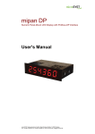
miface PB
Universal Interface Profibus DP / Serial Interface RS232/485/422
User’s Manual
microSYST Systemelectronic GmbH, Albert-Einstein-Straße 7, 92637 Weiden
Tel. +49 961 39166-0, Fax +49 961 39166-10, www.microsyst.de, [email protected]
miface PB
Universal Interface Profibus DP / Serial Interface RS232/485/422
Table of Contents
1
GENERAL
3
2
TECHNICAL DATA
3
3
4
2.1
Profibus DP Interface
2.1.1 Characteristic Data
2.1.2 DP Configuration Data
2.1.3 DP Diagnosis Data
2.1.4 DP Parameter Data
2.1.5 DP Output Data
2.1.6 DP Input Data
4
4
5
6
6
6
6
2.2
Transmit Data Frame (DP Output -> Serial Interface)
7
2.3
Receive Data Frame (Serial Interface -> DP Input)
8
CONNECTOR PIN ASSIGNMENTS
9
3.1
LEDs
9
3.2
Connectors
10
3.3
Settings
11
APPENDIX
13
4.1
Warranty / Liability
13
4.2
Declaration of Conformity
14
4.3
Versions Overview
15
Page 2
microSYST Systemelectronic GmbH, Albert-Einstein-Straße 7, 92637 Weiden
Tel. +49 961 39166-0, Fax +49 961 39166-10, www.microsyst.de, [email protected]
miface PB
Universal Interface Profibus DP / Serial Interface RS232/485/422
1 General
Using the universal interface, Profibus DP output data are transmitted via
the serial RS interface, and frames received by the serial RS interface are
copied to the Profibus DP input data.
The mechanical design is laid out for top-hat rail mounting.
Settings for bus termination, address and options can be made simply by
using DIP switches.
2 Technical Data
Specifications
Interface 1:
Baud rate:
Addresses:
Profibus DP
9,6 kBaud…12 MBaud
0…126
Interface 2:
Baud rate:
Data formats:
Parity:
RS232 / 485 / 422
1200 to 115200 baud
7 / 8 Bit
7 Bit: none (2 stop bits),
8 Bit: even, odd, none (1 stop bit)
Operating voltage:
Power consumption:
+12…+30 VDC
approx. 200 mA at 12 VDC
approx. 100 mA at 24 VDC
Housing:
Housing size:
Mounting:
Protection:
Operating temperature:
Storage temperature:
aluminium profile
26 x 105 x 70 mm (W x H x D)
to 35 mm DIN top hat rail
Front panel: IP 00
0…+50 °C
-25…+60 °C
Page 3
microSYST Systemelectronic GmbH, Albert-Einstein-Straße 7, 92637 Weiden
Tel. +49 961 39166-0, Fax +49 961 39166-10, www.microsyst.de, [email protected]
miface PB
Universal Interface Profibus DP / Serial Interface RS232/485/422
2.1 Profibus DP Interface
2.1.1 Characteristic Data
ID Number:
05D0h
GSD File:
MICR05D0.GSD
Cyclical User Data:
max. 200 bytes output,
max 200 bytes input,
max. 300 bytes output + input
Standard Configuration:
2x 0x3F (32 input-/output bytes)
Parameter Data:
Standard 7 Byte
User PRM:
none
Diagnosis:
Standard 6 Byte
External Diagnosis:
none
Transmission Speed:
9.6 kBaud / 19.2 kBaud / 93.75 kBaud /
187.5 kBaud / 500 kBaud / 1.5 MBaud /
3 MBaud, 6 MBaud, 12 MBaud
Protocol:
Profibus DP DIN19245, part 3
Page 4
microSYST Systemelectronic GmbH, Albert-Einstein-Straße 7, 92637 Weiden
Tel. +49 961 39166-0, Fax +49 961 39166-10, www.microsyst.de, [email protected]
miface PB
Universal Interface Profibus DP / Serial Interface RS232/485/422
2.1.2 DP Configuration Data
The configuration of the Profibus interface normally happens using the
GSD file. It is initially imported into the "Device Catalog" of the
configuration software. Subsequently, the Profibus interface can be
“dragged” into the bus system and then be configured.
With the configuration, the user can individually adapt data width within
the data transfer. Data widths of 1 to 16 bytes maximum are possible.
By specifying these identifiers in any order, the desired total data width is set
for both the input and the output data.
Data Identifier
0x10
0x11
:
0x1F
Number of Bytes
1
2
:
16
Function / Description
Input data
Input data
:
Input data
0x20
0x21
:
0x2F
1
2
:
16
Output data
Output data
:
Output data
0x30
0x31
:
0x3F
1/1
2/2
:
16/16
Input / output data (1 byte each)
Input / output data (2 bytes each)
Input / output data (16 bytes each)
The maximum number of input and output bytes is 200 bytes each.
However a total number of 300 bytes (input + output) may not be exceeded.
Default configuration: 2x 0x3F = 32 input and 32 output bytes
Page 5
microSYST Systemelectronic GmbH, Albert-Einstein-Straße 7, 92637 Weiden
Tel. +49 961 39166-0, Fax +49 961 39166-10, www.microsyst.de, [email protected]
miface PB
Universal Interface Profibus DP / Serial Interface RS232/485/422
2.1.3 DP Diagnosis Data
The interface does not support any extended diagnosis data. Default
diagnosis is utilised.
2.1.4 DP Parameter Data
The User_Prm_Data are not utilised by the interface. However, a test is run
to determine whether or not User_Prm_Data are transferred by the Profibus
master. If User_Prm_Data are transferred, Profibus initialisation is disabled
and the slave must be reconfigured and parameterised.
Note:
Standard parametrisation is required and is normally installed by the utilised
DP configurators.
2.1.5 DP Output Data
The interface supports output data which have been configured to the
length selected during configuration. The minimum number of output data
is 0 bytes, the maximum number is 200 bytes.
Send frames are entered to the output data.
At least 3 output bytes are required if send frames are used.
2.1.6 DP Input Data
The interface supports input data which have been configured to the
length selected during configuration. The minimum number of input data
is 0 bytes, the maximum number is 200 bytes.
Receive frames are entered into the input data.
At least 3 input bytes are required if receive frames are used.
Page 6
microSYST Systemelectronic GmbH, Albert-Einstein-Straße 7, 92637 Weiden
Tel. +49 961 39166-0, Fax +49 961 39166-10, www.microsyst.de, [email protected]
miface PB
Universal Interface Profibus DP / Serial Interface RS232/485/422
2.2 Transmit Data Frame (DP Output -> Serial Interface)
DP Output
Byte 1
Byte 2 Byte 3
Byte 4
Toggle byte Length Frame byte 1 Frame byte 2
byte = n
...
...
Byte n + 2
Frame byte n
In order to transmit a frame via the serial interface, the individual frame bytes
must be entered at the Profibus side as output bytes 3 through (n + 2). After the
length byte (= frame length n) has been entered, the toggle byte must be
changed in order to start transmission.
The toggle byte is not checked again until after the current frame has been
transmitted. Transmission duration can be estimated based upon frame length
and baud rate.
*Transmission duration (max.) = Frame length x (11 / baud rate) x 1.2
In addition, the delay through the processing on the master side, the Profibus
transmission and the processing on slave side (< 5 ms) must be considered.
In many cases it is also possible to simply wait for the (mostly existing)
response frame which is visible through the toggle byte change at DP
input side.
If too few DP output bytes have been configured, the frame is shortened
accordingly!
Example:
Transmission of two frames (‘ABC’ and ‘DE’) one after the other in rapid
succession to the RS interface
Sequence
▼
1. Start of Profibus DP
communication
2. Enter frame data
Byte 1
00H
Byte 2
00H
DP Output
Byte 3
Byte 4
00H
00H
Byte 5
00H
00H
03H
41H („A“)
42H („B“)
43H („C“)
3. Transmit frame and
wait for transmission*
4. Enter data for next frame
01H
03H
41H
42H
43H
01H
02H
44H („D“)
45H („E“)
XXH
5. Transmit next frame and
wait for transmission*
02H
02H
44H
45H
XXH
Page 7
microSYST Systemelectronic GmbH, Albert-Einstein-Straße 7, 92637 Weiden
Tel. +49 961 39166-0, Fax +49 961 39166-10, www.microsyst.de, [email protected]
miface PB
Universal Interface Profibus DP / Serial Interface RS232/485/422
2.3 Receive Data Frame (Serial Interface -> DP Input)
DP Input
Byte 3
Byte 4
Frame byte 1 Frame byte 2
Byte 1
Byte 2
Toggle byte Length
byte = n
...
...
Byte n + 2
Frame byte n
Each time a frame has been received via the serial interface (frame end
recognised by means of timeout), it is entered as input bytes 3 through (n + 2),
and the frame length (n) is entered as byte 2 (= length byte). The toggle byte is
also increased by 1.
Thus only the toggle byte needs to be monitored at the Profibus side. As soon as
it’s value has changed, data can be read out from the received frame.
If too few DP input bytes are configured, the frame is shortened correspondingly!
The toggle byte is always set to 0 after Profibus communication is initialised.
Example:
Two frames (“Hello” and “World”) are received via the RS interface.
Sequence
▼
1. Start of
Profibuscommunication
2. Frame “Hello“
was received
3. Frame “World“
was received
Byte 1
Byte 2
Byte 3
DP Input
Byte 4
Byte 5
Byte 6
Byte 7
00H
00H
00H
00H
00H
00H
00H
01H
05H
48H (“H“)
65H (“e“)
6CH (“l“)
6CH (“l“)
41H (“o“)
02H
05H
57H (“W“)
41H (“o“)
72H (“r“)
6CH (“l“)
64H (“d“)
Page 8
microSYST Systemelectronic GmbH, Albert-Einstein-Straße 7, 92637 Weiden
Tel. +49 961 39166-0, Fax +49 961 39166-10, www.microsyst.de, [email protected]
miface PB
Universal Interface Profibus DP / Serial Interface RS232/485/422
3 Connector Pin Assignments
Front Side
Bottom Side
Power Supply
S2
LED red
LED green
S3
Profibus DP
S1
RS232/485/422
3.1 LEDs
LED
Status
ON
red (FAULT)
green (RUN)
OFF
OFF
ON
temporary OFF
(blinking)
Meaning
no Profibus DP connection
or RAM error (if green LED OFF)
Profibus DP connection established
Controller is not running (hardware error)
Controller is running
UART communication
(frame has been sent or received)
Page 9
microSYST Systemelectronic GmbH, Albert-Einstein-Straße 7, 92637 Weiden
Tel. +49 961 39166-0, Fax +49 961 39166-10, www.microsyst.de, [email protected]
miface PB
Universal Interface Profibus DP / Serial Interface RS232/485/422
3.2 Connectors
Power Supply
Pin
1
2
3
Assignment
+12…+30 VDC
GND
PE
RS
Pin
1
2
3
4
5
6
7
8
RS232
RxD
TxD
GND
RS485
RS422
GND
Rx/Tx +
Rx/Tx -
GND
Rx +
Rx Tx +
Tx PE
PE
PE
See chapter „Settings“ for interface selection.
Profibus DP
Pin
1
2
3
4
5
6
7
8
9
Assignment
Rx+ / Tx+
RTS
GND, electrically isolated
+5V, electrically isolated
Rx- / Tx-
Page 10
microSYST Systemelectronic GmbH, Albert-Einstein-Straße 7, 92637 Weiden
Tel. +49 961 39166-0, Fax +49 961 39166-10, www.microsyst.de, [email protected]
miface PB
Universal Interface Profibus DP / Serial Interface RS232/485/422
3.3 Settings
Notes:
•
•
•
See the marking on the DIP switches to determine ON/OFF positions
The DIP switches may generally only be changed while power is OFF!
Delivery settings: Following grey-coloured table entries
Switch S1 / S3-DIP7: Interface Selection
Interface
RS232
RS422
without bus termination
RS422
with bus termination
RS485
without bus termination
RS485
with bus termination
Switch S1
DIP3 DIP4
OFF
OFF
DIP5
OFF
DIP6
OFF
Switch S3
DIP7
OFF
ON
OFF
OFF
OFF
OFF
ON
OFF
ON
OFF
OFF
ON
ON
ON
OFF
ON
ON
ON
OFF
OFF
OFF
OFF
ON
ON
ON
ON
ON
OFF
DIP1
ON
DIP2
OFF
OFF
Switch S2: Profibus Address, Bus Termination
DIP Switch
DIP 1
DIP 2
DIP 3
DIP 4
DIP 5
DIP 6
DIP 7
DIP 8
DIP 9
DIP 10
Function
DP address Bit 20 (ON = 1)
DP address Bit 21 (ON = 2)
DP address Bit 22 (ON = 4)
DP address Bit 23 (ON = 8)
DP address Bit 24 (ON = 16)
DP address Bit 25 (ON = 32)
DP address Bit 26 (ON = 64)
reserved (= OFF)
both ON: Profibus bus termination activated
both OFF: no Profibus bus termination
Note: Only DP addresses 0 through 126 are allowed!
Delivery setting: DP address = 3
Page 11
microSYST Systemelectronic GmbH, Albert-Einstein-Straße 7, 92637 Weiden
Tel. +49 961 39166-0, Fax +49 961 39166-10, www.microsyst.de, [email protected]
miface PB
Universal Interface Profibus DP / Serial Interface RS232/485/422
Switch S3: RS Interface Parameters
Baud Rate
1200
2400
4800
9600
19200
38400
57600
115200
DIP 1
OFF
ON
OFF
ON
OFF
ON
OFF
ON
Data Format
8/N/1
8/E/1
8/O/1
7/N/2
DIP 4
OFF
ON
OFF
ON
Receive Timeout*
short
DIP 6
OFF
long
ON
DIP 2
OFF
OFF
ON
ON
OFF
OFF
ON
ON
DIP 3
OFF
OFF
OFF
OFF
ON
ON
ON
ON
DIP 5
OFF
OFF
ON
ON
Baud Rate / Receive Timeout
1200 Baud / 29 ms
2400 Baud / 16 ms
4800 Baud / 9 ms
9600 Baud / 6 ms
19200 Baud / 4 ms
38400 Baud / 3 ms
57600 Baud / 3 ms
115200 Baud / 3 ms
1200 Baud / 200 ms
2400 Baud / 100 ms
4800 Baud / 50 ms
9600 Baud / 25 ms
19200 Baud / 13 ms
38400 Baud / 10 ms
57600 Baud / 10 ms
115200 Baud / 10 ms
* Determines, after which duration a receive frame is considered to be finished
and should be announced to the Profibus DP (duration after the last received
byte). The interval between the individual frame bytes may not exceed this
duration (otherwise this would be interpreted as the end of the frame).
Mode
Standard
migan
(not relevant)
DIP 8
OFF
ON
Page 12
microSYST Systemelectronic GmbH, Albert-Einstein-Straße 7, 92637 Weiden
Tel. +49 961 39166-0, Fax +49 961 39166-10, www.microsyst.de, [email protected]
miface PB
Universal Interface Profibus DP / Serial Interface RS232/485/422
4 Appendix
4.1 Warranty / Liability
For the product, liability is assumed for defects, which existed at the
delivery date according to our General Terms and Conditions.
Technically changes as well as errors are excepted. A claim for delivery of a new
product does not exist. The buyer has to check the received product immediately
and indicate evident defects at the latest 24 hours after detection. Nonobservance of notification requirements is equated with acceptance of the defect.
Not immediately visible defects have to be indicated immediately after their
perception too.
Generally, defects and their symptoms must be described as accurately
as possible in order to allow for reproducibility and elimination. The buyer
must provide for access to the relevant device and all required and/or
useful information at no charge and must make all of the required data
and machine time available free of charge.
The guarantee does not cover defects, which result from non-observance
of the prescribed conditions of use, or from improper handling.
If the device has been placed at the disposal of the buyer for test
purposes and has been purchased subsequent to such testing, both
parties agree that the product is to be considered “used” and that it has
been purchased “as is”. No guarantee claims may be made in such
cases.
The General Terms and Conditions of microSYST Systemelectronic
GmbH in current version apply as well.
Page 13
microSYST Systemelectronic GmbH, Albert-Einstein-Straße 7, 92637 Weiden
Tel. +49 961 39166-0, Fax +49 961 39166-10, www.microsyst.de, [email protected]
miface PB
Universal Interface Profibus DP / Serial Interface RS232/485/422
4.2 Declaration of Conformity
EG-Konformitätserklärung
Declaration of EC-Conformity
Produktbezeichnung:
Product name:
miface PB
Produktbeschreibung:
Product description:
Universa-Interface Profibus-DP / Serielle Schnittstelle /
Universal Interface Profibus DP / Serial Interface
Hersteller:
Manufacturer:
microSYST Systemelectronic GmbH
Albert-Einstein-Straße 7
92637 Weiden
Das bezeichnete Produkt stimmt mit
der folgenden Europäischen Richtlinie
überein:
We herewith confirm that the above
mentioned product meets the
requirements of the following standard:
Die Übereinstimmung des bezeichneten
Produktes mit den Vorschriften der
Richtlinie wird nachgewiesen durch die
vollständige Einhaltung folgender Normen:
The correspondence of the above mentioned
product with these requirements is proved by
the fact that these products meet with the
following single standards:
Nummer
Europäische Norm
EN61000-6-2:2006
EN61000-6-3:2007
2004/108/EG
Bezeichnung
Elektromagnetische
Verträglichkeit (EMV)
Weiden, den 23.05.2012
Harald Kilian
Leiter operatives Geschäft / COO
Prokurist / Authorized Signatory
Page 14
microSYST Systemelectronic GmbH, Albert-Einstein-Straße 7, 92637 Weiden
Tel. +49 961 39166-0, Fax +49 961 39166-10, www.microsyst.de, [email protected]
miface PB
Universal Interface Profibus DP / Serial Interface RS232/485/422
4.3 Versions Overview
Version
Date
1.00
1.10
1.20
1.30
2012-09-17
2013-03-26
2013-10-17
2014-07-22
Comments
Kreuzer, Nickl: Document created
Company address, warranty
Logo
Operating voltage
Certified per DIN ISO 9001.
Page 15
microSYST Systemelectronic GmbH, Albert-Einstein-Straße 7, 92637 Weiden
Tel. +49 961 39166-0, Fax +49 961 39166-10, www.microsyst.de, [email protected]