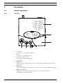
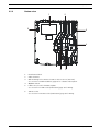
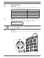
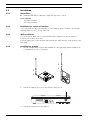
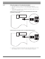
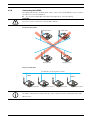
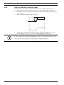
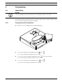
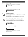
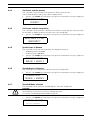
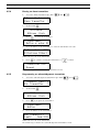
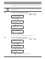
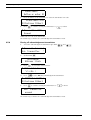
1
Main Unit F.01U.278.515 | V1.0 | 2012.11 en User Manual Main Unit Table of Contents | en 3 Table of Contents 1 Safety instructions 6 1.1 Importance of safety instructions 6 1.2 Disregarding safety rules 6 1.3 Environmental conditions 6 1.4 General safety instructions 6 1.4.1 Observation and information 7 2 Description 8 2.1 General description 8 2.1.1 Top view 8 2.1.2 Bottom view 9 2.1.3 Front view 10 2.1.4 Rear view 10 2.2 Detailed description 11 2.2.1 Loudspeaker 11 2.2.2 Display 11 2.2.3 Keyboard 11 2.2.4 RS-232 interface 13 2.2.5 RS-485 interface 14 2.2.6 Antenna 14 3 Installation 15 3.1 Unpacking 15 3.1.1 List of contents 15 3.2 Installation 16 3.2.1 Generalities 16 3.2.2 Installation on a piece of furniture 16 3.2.3 Wall installation 16 3.2.4 Installing the antenna 16 3.2.5 Connecting to the mains 17 3.2.6 Connecting the RS-232 17 3.2.7 Setting the jumpers on the communication board 18 3.2.8 Connecting the RS-485 19 3.2.9 Setting the 100 Ohm termination jumper 20 4 Programming 21 4.1 Generalities 21 4.1.1 Programming with the keyboard 21 4.1.2 Programming with the NPS software 22 4.1.3 Exit the programming mode and cancel entries 22 4.1.4 Key not allowed 22 4.1.5 Locking and unlocking the keyboard 22 4.1.6 Programming time-out 22 4.2 First use 22 4.2.1 List of original factory settings 23 4.2.2 Language 24 Bosch Security Systems User Manual F.01U.278.515 | V1.0 | 2012.11 4 en | Table of Contents Main Unit 4.2.3 Locating mode 24 4.2.4 Display mode 24 4.3 Parameters 25 4.3.1 Access to parameters 25 4.3.2 List of parameters 25 4.3.3 Programming the unit language 25 4.3.4 Date and time setting 26 4.3.5 RS-232 output setting 27 4.3.6 Local acknowledgement setting 31 4.3.7 Output relay setting 31 4.3.8 Accompany mode 32 4.3.9 Radio noise check 32 4.3.10 Tracking function 33 4.3.11 Dementia criterion 33 4.3.12 Assistance alarm from MIYS35Q, MIYS37Q and MIYS37L transmitters 33 4.4 Special settings 34 4.4.1 Displaying firmware version 34 4.4.2 Resetting all the parameters 34 4.4.3 Assistance and fire priority 35 4.4.4 Assistance and fire non priority 35 4.4.5 Special texts in German 35 4.4.6 Standard texts in German 35 4.4.7 Standard Mode selection 35 4.4.8 Universal Mode selection 36 4.4.9 Maximum number of alarm transmitters 37 4.4.10 Maximum number of acknowledgement transmitters 37 4.4.11 Maximum number of events buffered 37 4.4.12 Disabling the daily messages check 37 4.4.13 RS232 message setting 37 4.5 Transmitters 38 4.5.1 Starting programming 38 4.5.2 Programming an alarm transmitter 38 4.5.3 Checking an alarm transmitter 39 4.5.4 Erasing an alarm transmitter 40 4.5.5 Programming an acknowledgement transmitter 40 4.5.6 Checking an acknowledgement transmitter 41 4.5.7 Erasing an acknowledgment transmitter 41 4.5.8 Erasing all acknowledgement transmitters 42 5 Operation 43 5.1 Adjusting the loudspeaker volume 43 5.2 Consulting the alarm or event buffer 43 5.2.1 Switching between alarm and event buffers indication 44 5.2.2 Display indications 44 5.2.3 Local acknowledgement 45 5.2.4 Disconnecting a Relay Unit 45 6 Troubleshooting and error messages 46 6.1 "Radio in use" message 46 F.01U.278.515 | V1.0 | 2012.11 User Manual Bosch Security Systems Main Unit Table of Contents | en 5 6.2 "Alarm Transmitter NOT stored" message 46 6.3 "Alarm Transmitter already stored" message 46 6.4 "Ack. Transmitter NOT stored" message 46 6.5 "Ack. Transmitter already stored" message 46 6.6 The green button does not work 46 7 Maintenance 47 7.1 Checking the system 47 7.2 Monitoring the power supply 47 7.3 Monitoring the backup battery 47 7.4 Cleaning 48 7.5 Parts replacement 48 7.5.1 Disassembling the unit 48 7.5.2 Backup battery replacing 49 8 Disposal 50 8.1 Disassembly 50 8.2 Returning to the manufacturer 50 8.3 Materials 50 8.4 Battery 50 A Appendix 51 A.1 Electrical specifications 51 A.2 Dimensions and weight 51 A.3 Environmental conditions 51 A.4 List of criteria 52 A.5 Paging systems specifications 53 A.5.1 ESPA 4.4.4. protocol 53 A.5.2 POCSAG protocol 55 A.5.3 DeTeWe protocol 56 A.5.4 Medicall 800 protocol 57 A.6 DECT phone system specifications 58 A.6.1 Multitone DECT systems with P318 interface 58 A.7 Connectors 59 A.7.1 LINE socket (unit bottom) 59 A.7.2 Power socket (unit bottom) 59 A.7.3 RS-232 socket (unit rear) 59 A.7.4 RS-485 socket (unit rear) 59 Bosch Security Systems User Manual F.01U.278.515 | V1.0 | 2012.11 6 1 en | Safety instructions Main Unit Safety instructions NOTICE! The user and installer should read and understand this chapter before any intervention on the Main Unit. 1.1 Importance of safety instructions Each safety and protection instruction in this manual must be adhered to in order to avoid personnel injuries, property damages or environmental pollution. In a similar manner, the legal bylaws, the measures in prevention of accidents and for the protection of the environment, as well as the recognized technical rules aiming at appropriate and safe working conditions which as applied in the country and at the place of use of the Main Unit must be adhered to. 1.2 Disregarding safety rules Disregarding the safety rules, as well as existing legal and technical regulations, may lead to accidents, to property damages or to environmental pollution. 1.3 Environmental conditions NOTICE! The Main Unit must not be located near a water tap or any other source of water. The electrical safety of the unit is only guaranteed if the electrical installation is conform to the national regulation and if this installation works properly. The Main Unit may not be used in buildings prone to fire and explosion hazards. NOTICE! The Main Unit may not be used under exposure to the direct sunlight, to heat, to dust or to an excessive humidity (only use the equipment in a clean environment). Install the Main Unit in a dry place, away from any source of heat. CAUTION! Interferences Avoid immediate proximity to other electric devices such as a television. 1.4 General safety instructions DANGER! Electrocution During maintenance operations, when the Main Unit is powered and its casing is removed, it may not be left unattended. CAUTION! The Main Unit may only be connected to the electrical sources as described in Section A.1 Electrical specifications, page 51. F.01U.278.515 | V1.0 | 2012.11 User Manual Bosch Security Systems Main Unit Safety instructions | en 7 CAUTION! Maintenance and repairs may only be performed in conformance with the instructions and by authorized technical personnel only. The sole possession of the user manual does not allow the personnel to perform any kind of repair on the Main Unit. Take into account all the warnings and follow all the instructions displayed on the Main Unit and those which are printed in the documentation. Never try to use replacement pieces other than those authorized by the manufacturer of the Main Unit. CAUTION! It is mandatory to use the products specified in the present user manual to clean the Main Unit. If you plan to use another product, only do so after having obtained the authorization of the manufacturer. DANGER! The Main Unit contains highly sensitive electronic components. It should be opened only in an ESD protected environment with respect to the following precautions: 1. Discharge yourself from electrostatic loads by touching a grounded conductive surface before opening the unit. 2. Avoid touching conductive parts inside the unit if not absolutely necessary. CAUTION! Never let any liquid enter the system. In case of liquid spill inside the Main Unit, act immediately as follows: 1.4.1 1. Switch off the unit using the main switch under the casing. 2. Unplug the power supply adaptor. 3. Dry up the unit. 4. Clean the unit. 5. Check that the unit switches on correctly. Observation and information In case of defective operation or any other technical incident for which no remedy is described in this manual, please contact immediately your local representative. Bosch Security Systems User Manual F.01U.278.515 | V1.0 | 2012.11 8 en | Description Main Unit 2 Description 2.1 General description 2.1.1 Top view 1 2 3 7 1. 6 5 4 Loudspeaker. See Section 2.2.1 Loudspeaker, page 11. 2. Display. See Section 2.2.2 Display, page 11. 3. Keyboard, under the cover. See Section 2.2.3 Keyboard, page 11. 4. LED Indicator 5. Yellow button Used to view more details about the event or alarm currently displayed (date and time, position, etc...). 6. Green button Used to acknowledge an alarm locally, see Section 5.2.3 Local acknowledgement, page 45. 7. Red button with light This button is not used. Pressing the button does not activate a function. The light blinks red during an alarm. F.01U.278.515 | V1.0 | 2012.11 User Manual Bosch Security Systems Main Unit 2.1.2 Description | en 9 Bottom view 1 2 3 3 4 6 1. Identification label. 2. Cable channels. 3. 5 Wall mounting holes. Distance between holes is 6.2 in (157 mm). See Section 3.2.3 Wall installation, page 16 for a detailed description. 4. ON/OFF switch. 5. LINE socket, used for firmware update. See Section A.7.1 LINE socket (unit bottom), page 59 for wiring. 6. 10V AC socket. See Section A.7.2 Power socket (unit bottom), page 59 for wiring. Bosch Security Systems User Manual F.01U.278.515 | V1.0 | 2012.11 10 en | Description 2.1.3 Main Unit Front view 1 1. 2.1.4 LED Indicator Status LED Standby mode (normal operation) Green (permanent) Backup battery low Green (blinking) Power supply disconnected Green (flashing) Help, assistance or fire Red (blinking) Programming mode Orange (blinking) Rear view 1 1. 2 3 RS-232 connector See Section A.7.3 RS-232 socket (unit rear), page 59 for wiring. 2. RS-485 connector See Section A.7.4 RS-485 socket (unit rear), page 59 for wiring. 3. F.01U.278.515 | V1.0 | 2012.11 Antenna connector User Manual Bosch Security Systems Main Unit Description | en 2.2 Detailed description 2.2.1 Loudspeaker 11 When one of the following alarms or messages is received by the Main Unit, the internal loudspeaker is activated until acknowledgement. 2.2.2 Status Loudspeaker Power supply disconnected Dual-tone beep every minute Call for help, reserve call, technical call 4 second interval, one tone Error message 15 second interval, one tone Disconnection of a relay unit from RS485-bus 1 minute interval, one tone Call for assistance / fire alarm Continuously dual-tone beep Local acknowledgement Short beep Display The Main Unit is equipped with a 2 x 20 characters display that guides the operator during the programming. During normal operation, alarms and messages are displayed. Main Unit V2.01 BN111.240.00A NOTICE! This user manual is written for the unit language English USA. Certain displays may differ for the unit language English UK. 2.2.3 Keyboard The keyboard has 21 alphanumeric keys. They are used to program the Main Unit or during normal operation. OFF OK ON C Bosch Security Systems User Manual T P F.01U.278.515 | V1.0 | 2012.11 12 en | Description Keys Main Unit Programming Mode Normal Operation Access to parameters programming. Not used. See Section 4.3 Parameters, page 25. Access to transmitters programming. Not used. See Section 4.5 Transmitters, page 38. Scroll up to the next parameter. Increase the volume of the loudspeaker. See Section 5.1 Adjusting the loudspeaker volume, page 43. Scroll down to the next parameter. Decrease the volume of the loudspeaker. See Section 5.1 Adjusting the loudspeaker volume, page 43. Set a parameter value to OFF or to go to the Scroll down to the previous alarm/event. previous programming field. Set a parameter value to ON or to go to the next Scroll up to the next alarm/event. programming field. Confirm a value or a command. Not used. Cancel an entry or a command. Not used. Quit the programming mode. Check the value of a parameter or a transmitter. Check the status of the backup battery. See Section 7.3 Monitoring the backup battery, page 47. Not used. Not used. NPS programming function. See Not used. Section 4.1.2 Programming with the NPS software, page 22. Enter a value. Not used. Erase all programmed acknowledgement Not used. to transmitters during a specific procedure. See Section 4.5.8 Erasing all acknowledgement transmitters, page 42. Disable the beep codes and delete the POS Not used. indication. See Section 4.3.5 RS-232 output setting, page 27 and Section Example of programming, Page 28. Enter a value or to set the default values. Launch the event/alarm display mode. See Section 4.3.5 RS-232 output setting, page 27. then No effect. F.01U.278.515 | V1.0 | 2012.11 Lock and unlock the keyboard. User Manual Bosch Security Systems Main Unit 2.2.4 Description | en 13 RS-232 interface A 9-pole SUB-D connector at the rear of the housing can be used for connection to – a printer – a paging system – a DECT phone system – a PC with Alarm Management Software. For the hardware configuration of this interface, see Section 3.2.6 Connecting the RS-232, page 17. For the programming of this interface, see Section 4.3.5 RS-232 output setting, page 27. For the wiring of the connector, see Section A.7.3 RS-232 socket (unit rear), page 59. Connection to a printer To protocol all events, a printer with serial connection (RS-232 Interface) and endless paper should be used. Printers with a parallel port can be used together with an intermediate serial - parallel converter. NOTICE! The paper printout corresponds to the indication at the display of the Main Unit. Characteristics – Data rate: 9600 Bauds. – Transmission: asynchronous – 10 bit-structure (1 start bit, 8 data bits without parity, 1 stop bit). The operating status of the printer cannot be tested (switched on/off, paper status). An RS-232 printer is mandatory. Connection to a paging system The Main Unit uses several protocols: standard ESPA 4.4.4. with RPE670/i-page, POCSAG, DeTeWe and Medicall 800. See Section A.5 Paging systems specifications, page 53 for more information about these protocols. Connection to a DECT phone system The Main Unit can transfer the received alarms to DECT handsets Multitone CH60 or CH70. See Section A.6 DECT phone system specifications, page 58 for more information about this system. Connection to a PC using an Alarm Management Software At connection / disconnection of a PC using an Alarm Management Software, events are generated. The loudspeaker is disabled during the connection. NOTICE! Alarms/messages arriving in the alarm buffer are repeated every 3 minutes until acknowledgement. A technical failure, for example a power outage, is treated as an event. No acknowledgement is therefore necessary. See Section 5.2 Consulting the alarm or event buffer, Page 43. Bosch Security Systems User Manual F.01U.278.515 | V1.0 | 2012.11 14 en | Description 2.2.5 Main Unit RS-485 interface One Main Unit and up to 32 Relay Units can be connected by a RS-485 bus. The bus must be connected to pins 2 and 5 of the RS-485 socket. For connector wiring, see Section A.7.4 RS-485 socket (unit rear), page 59. NOTICE! Keep polarity equal when connecting further units to the RS485 bus! NOTICE! Maximum RS485-bus length: 3’900 ft (1200 m). Use only one twisted pair cable for the interconnection. NOTICE! The receiver units located at the two ends of the bus must be terminated with a 100 Ohm resistor. See Section 3.2.8 Connecting the RS-485, page 19 for more information about the jumper setting. In this configuration, you always should connect the Main Unit first. The Relay Units must then be connected to the RS485-bus one by one, not at the same time. Relay output In the same connector, a potential free contact is available. It is a low current switching contact. The relay (potential free, switching power max. 48 V / 0.5 A) is activated at a call for help, call for assistance or fire alarm. This relay can be set as closing or switching contact (cycle of 10 seconds on / 10 seconds off). This feature can be used to drive a signal lamp for example. 2.2.6 For connector wiring, see Section A.7.4 RS-485 socket (unit rear), page 59. For relay setting, see Section 4.3.7 Output relay setting, page 31. Antenna The antenna is connected to the Main Unit using the adapter supplied with the unit. F.01U.278.515 | V1.0 | 2012.11 See Section 3.2.4 Installing the antenna, page 16. User Manual Bosch Security Systems Main Unit Installation | en 3 Installation 3.1 Unpacking 15 The Main Unit is carefully packed for transportation. The components contained in the box are protected, but should be handled with care. Store the packaging material for further use (storage or transport). 1. Take all components out of the box and place the Main Unit on the working space. 2. Check each component in the box, in accordance with the list of contents below. 3. Check that the Main Unit and its accessories have not been damaged during transportation. In case of defective or missing equipment, do not try to install the Main Unit. 3.1.1 Contact immediately your local representative. List of contents Description Main Unit Power supply adaptor (US) 115VAC/10VAC Antenna 434MHz 1/2 L=13.4 in (34 cm) FME Straight adapter BFME-TNC Right angled bended adapter BFME-ETNC 6.6 ft (2 m) Cable FCC 6/4 Main Unit User Manual Bosch Security Systems User Manual F.01U.278.515 | V1.0 | 2012.11 16 en | Installation Main Unit 3.2 Installation 3.2.1 Generalities Install the Main Unit in a dry place, away from any source of heat. Tools required: 3.2.2 – Torx T20 screwdriver. – Torx T10 screwdriver. Installation on a piece of furniture It is recommended to place the Main Unit on a non-slippery surface. However, do not place anything (blanket or lace) on top of the unit. 3.2.3 Wall installation You can fasten the Main Unit on a smooth wall surface using two screws. The distance between holes is 6.2 in (157 mm). Power and phone line cords should be placed inside the cable channels on the bottom of the Main Unit. 3.2.4 Installing the antenna 1. Use the straight adapter (4) for wall installation or the right angled bended adapter (3) for installation on a piece of furniture. 2 4 2 3 2. Fasten the adapter (3) or (4) on the antenna connector (1). 1 3. F.01U.278.515 | V1.0 | 2012.11 Fasten the antenna (2) on the adapter. User Manual Bosch Security Systems Main Unit 3.2.5 Installation | en 17 Connecting to the mains The Main Unit is powered by an adaptor (115/10 VAC). CAUTION! In case of a different supply, the equipment must fulfill isolation requirements according to EN60950 standard (last edition). 1. Plug the power adaptor into a power outlet placed near the unit. It should be easily accessible at any time. 1 2. Connect the cable to the socket labeled 10V AC (1), under the unit. For connector wiring, see Section A.7.2 Power socket (unit bottom), page 59. 3.2.6 Connecting the RS-232 Connect the device to the 9-pole SUB-D connector (1) at the rear part of the housing. 1 For connector wiring, see Section A.7.3 RS-232 socket (unit rear), page 59. Bosch Security Systems User Manual F.01U.278.515 | V1.0 | 2012.11 18 en | Installation 3.2.7 Main Unit Setting the jumpers on the communication board 1. 2. Disassemble the unit; see Section 7.5.1 Disassembling the unit, page 48. Remove the communication board; see Section Removing the communication board, page 48. 3. Set the jumpers as required in your configuration. By default the jumpers are set for connection to a DECT phone system. Setting the jumpers for a DECT phone system, Alarm Management Software, NPS programming or Medicall 800: Setting the jumpers for Paging systems (except Medicall 800) and printers: 4. Assemble the communication board and the unit. This is basically the reverse of the disassembling procedure, see Section 7.5.1 Disassembling the unit, page 48. F.01U.278.515 | V1.0 | 2012.11 User Manual Bosch Security Systems Main Unit 3.2.8 Installation | en 19 Connecting the RS-485 One Main Unit and up to 32 Relay Units can be connected to an RS-485 bus. Please contact a specialist for a correct installation. See Section A.7.4 RS-485 socket (unit rear), page 59 for connector wiring. CAUTION! Do not use a star connection for the RS-485 network! Incorrect connection: Relay Unit 1 Relay Unit 2 Main Unit Relay Unit n Correct connection: RS-485 bus (1 twisted pair cable) 100 Ω Relay Unit n 100 Ω Relay Unit 2 Main Unit Relay Unit 1 NOTICE! The Main or Relay Units located at the two ends of the bus must be terminated with a 100 Ohm resistor. Bosch Security Systems User Manual F.01U.278.515 | V1.0 | 2012.11 20 en | Installation 3.2.9 Main Unit Setting the 100 Ohm termination jumper Within the Main or Relay Units, the RS-485 interface can be configured with a jumper. 1. Disassemble the unit as described in Section 7.5.1 Disassembling the unit, page 48. 2. Remove the communication board as described in Section Removing the communication board, page 48. 3. Put the 100 Ohm termination jumper J112 (1). 1 4. Assemble the communication board and the unit. This is basically the reverse of the disassembling procedure, see Section 7.5.1 Disassembling the unit, page 48. NOTICE! If you do not want to disassemble the Main Unit, you also can short-out pins 3 and 4 of the connector. This has the same effect as the jumper setting described above. See Section A.7.4 RS-485 socket (unit rear), page 59 for connector wiring. F.01U.278.515 | V1.0 | 2012.11 User Manual Bosch Security Systems Main Unit Programming | en 4 Programming 4.1 Generalities 21 NOTICE! In the programming mode, the Main Unit does not display any alarm or message! The Main Unit can be programmed either remotely by using a specific software package called NPS or directly by using the keyboard and display. 4.1.1 Programming with the keyboard Open the cover carefully and use the programming keys. P F F OK O N T O C To access the parameters programming, press then . See Section 4.3 Parameters, page 25 for more details. To access the special settings programming, press three times quickly. See Section 4.4 Special settings, page 34 for more details. To access the transmitters programming, press then . See Section 4.5 Transmitters, page 38 for more details. Bosch Security Systems User Manual F.01U.278.515 | V1.0 | 2012.11 22 en | Programming 4.1.2 Main Unit Programming with the NPS software The Main Unit can be programmed with a specific software called NPS. NOTICE! In order to program the Main Unit with this software, you should connect your PC to the Main Unit with an RS-232 cable. To connect and set the interface, see Section 3.2.6 Connecting the RS-232, page 17. Enable the programming 1. Press then . ¬ NPS Programming READY ?... 2. ¬ 4.1.3 . Programming NCall ............. Exit the programming mode and cancel entries 4.1.4 Confirm the command with Press once or several times. Key not allowed If you have pressed a key by mistake during the programming, a high-pitched beep is generated. 4.1.5 Locking and unlocking the keyboard Press then within one second to lock or unlock the keyboard. This function locks only the keyboard to prevent any false manipulation. The colored buttons on the left hand side are still available. When the keyboard is locked, a small lock appears at the bottom right of the display: DATE: TIME: 4.1.6 03.01.12 12:12:31 ¨ ½ Programming time-out Programming of the Main Unit terminates automatically if no entries are made on the keyboard for more than one minute. 4.2 First use At first use or when resetting all the parameters, you must program: the unit language the locating mode the display mode for the transmitters’ identification See Section 4.4.2 Resetting all the parameters, page 34. F.01U.278.515 | V1.0 | 2012.11 User Manual Bosch Security Systems Main Unit 4.2.1 Programming | en 23 List of original factory settings Parameter Original Factory Setting Page Language English USA 24 * Locating mode Off 24 * Display mode Floor/room/bed 24 Output RS-232 None 27 Forwarding of transmitter ID via the RS-232 interface Off 27 RPE 670 / i-page for paging systems No 28 Day / night mode No 28 Night start for paging or phone DECT systems 18h00 28 Night end for paging or phone DECT systems 06h00 28 ID paging for paging systems 2 28 ID system for paging systems 1 28 Beep codes allocated to each pager Help:7; Assi: 5; Ackn: 2 28 Number of digits for ESPA 4.4.4. 3 28 Mix Mode ESPA 4.4.4 / Alarm Management Software No 28 Digit for the POCSAG paging system address 4 30 First digit for DeTeWe paging system address 1 30 Local acknowledgement Yes 31 Access code for local acknowledgement No 31 Output relay function Closing 31 Output relay mode Help + Assistance 31 Accompany mode No 32 Lower limit for the accompany mode 231 32 Radio noise check Yes 32 Relay output in case of a radio noise event Off 32 Tracking function No 33 Dementia criterion No 33 Range of automatic dementia gates Standard 231-254 33 Assistance alarm from S35Q, S37Q and S37L transmitters Off 33 Assistance and fire priority No 35 Special texts in German No 35 Set to Universal Mode No 36 Conversion code for Universal Mode No 36 Last 300 ID codes blocked for Universal Mode No 36 Maximum number of alarm transmitters 500 37 Maximum number of acknowledgement transmitters 5 37 Maximum number of events buffered 100 37 Disabling the daily messages check Off 37 Repeat alarms timing to RS-232 output 3 minutes 37 Speaker volume Midrange 43 * Locating and display modes are set at first use. To change their value, reset the unit. Bosch Security Systems User Manual F.01U.278.515 | V1.0 | 2012.11 24 en | Programming 4.2.2 Main Unit Language Select the unit language. ¬ Language 0 English USA 4.2.3 £ See Section 4.3.3 Programming the unit language, page 25 for more details. Locating mode NOTICE! It is mandatory to perform a reset if you wish to change the value for the locating mode. See Section 4.4.2 Resetting all the parameters, page 34. Enable (ON) or disable (OFF) the indication of the transmitter position (locating mode) on the Main Unit display. LOCATING ? ( OFF / ON ) Press to disable or to enable the locating mode. WARNING! When the locating mode is disabled, the accompany mode, tracking function and dementia criterion are no longer available in the parameters programming. 4.2.4 Display mode NOTICE! It is mandatory to perform a reset if you wish to change the value for the display mode. See Section 4.4.2 Resetting all the parameters, page 34. Select the display mode for the transmitters’ identification. DISPLAY MODE ? (NUMBER / FL,RO,BE) 1. Press to select NUMBER or to select FL,RO,BE (floor, room, bed). 2. If you select NUMBER, then you must choose between a 3-digit display (single number) and an extended 4-sign display (digits and letters). NUMBERING RANGE (0-254 / 0-ZZZZ) 1. F.01U.278.515 | V1.0 | 2012.11 Press to select the 3-digit display 0-254 or User Manual to select the 4-sign display 0-ZZZZ. Bosch Security Systems Main Unit Programming | en 4.3 Parameters 4.3.1 Access to parameters 1. Press ¬ 2. then 25 to access the parameters. OK:Program ¤:Info Press to program these parameters or to check the value of each parameter. ¬ Parameter Nr. 00 Language £ 3. 4.3.2 Scroll with and . Press to confirm. Press to escape. List of parameters No. Parameter Reference 00 Language Section 4.3.3 Programming the unit language, page 25 01 Date and time Section 4.3.4 Date and time setting, page 26 02 RS-232 output Section 4.3.5 RS-232 output setting, page 27 03 Local acknowledgement Section 4.3.6 Local acknowledgement setting, page 31 04 Relay Output Section 4.3.7 Output relay setting, page 31 05 Accompany mode Section 4.3.8 Accompany mode, page 32 06 Radio noise check Section 4.3.9 Radio noise check, page 32 07 Tracking function Section 4.3.10 Tracking function, page 33 08 Dementia criterion Section 4.3.11 Dementia criterion, page 33 09 Assistance alarm Section 4.3.12 Assistance alarm from MIYS35Q, MIYS37Q and MIYS37L transmitters, page 33 4.3.3 Programming the unit language NOTICE! This parameter is set at first use. Here you can change it. See Section 4.2 First use, page 22. Choose between 7 language settings: – 0 = English USA – 1 = English UK – 2 = French – 3 = German – 4 = Italian – 5 = Dutch – 6 = Swedish 1. Select the parameter Nr. 00. ¬ Parameter Nr. 00 Language £ Bosch Security Systems User Manual F.01U.278.515 | V1.0 | 2012.11 26 en | Programming Main Unit 2. Press . ¬ Language 0 English USA £ 3. Select the language with and 4. Confirm the language selected with . . NOTICE! This user manual is written for the unit language English USA. Certain displays may differ for the unit language English UK. 4.3.4 Date and time setting 1. Select the parameter Nr. 01. ¬ Parameter Nr. 01 Date and Time ¡ 2. Press . ¬ Date and Time M·.DD.YY HH:MM:SS¡ 3. Set the month with 4. Go to the day with and . . ¬ Date and Time MM.D·.YY HH:MM:SS¡ 5. Set the day with 6. Go to the year with and . . ¬ Date and Time MM.DD.Y· HH:MM:SS¡ 7. Set the year with 8. Repeat the same operation for the time setting (HH:MM:SS). 9. Confirm the setting with F.01U.278.515 | V1.0 | 2012.11 and . . User Manual Bosch Security Systems Main Unit 4.3.5 Programming | en 27 RS-232 output setting NOTICE! Within the Main Unit, the RS-232 interface should be configured with jumpers. See Section 3.2.7 Setting the jumpers on the communication board, page 18. Select one of the following: – None – Printer – Alarm Management SW – PAGING – DECT 1. Select the parameter Nr. 02. ¬ Parameter Nr. 02 RS-232 Output ¡ 2. Press . ¬ RS-232 Output None 3. £ Set the desired value with and . Confirm with . NOTICE! For the values None and Printer, you do not have to define more parameters. Setting the interface to Alarm Management Software ¬ RS-232 Output Alarm Management SW¡ 1. Select Alarm Management SW in the RS-232 Output menu. Confirm with . ¬Alarm Management SW TRansm.ID>RS232:Off¡ 2. Activate (On) or deactivate (Off) the forwarding of transmitter ID via the RS-232 interface with Bosch Security Systems and . Default value is Off. User Manual F.01U.278.515 | V1.0 | 2012.11 28 en | Programming Main Unit Example of programming Hereafter is an example of the programming, with the following characteristics: – Locating mode = ON – Display mode = FL/RO/BE – Protocol = ESPA 4.4.4 – RPE 670 / i-page system = YES – Day / night transfer function = YES See Section A.5 Paging systems specifications, page 53. 1. Selected PAGING in the RS-232 Output menu. Confirm with ¬ RS-232 Output PAGING 2. ¡ Select the protocol (ESPA 4.4.4, POCSAG, DeTeWe or Medicall 800). Confirm with ¬ PAGING ESPA 4.4.4. 3. . ¡ Activate (YES) or deactivate (NO) the RPE 670 system with ¬ PAGING RPE 670 ? YES . and . ¡ 4. Confirm with . 5. Enter the ID number of the paging system (0-9) and the system (0-9). ¬ PAGING ESPA 4.4.4. ID PAG.:2 ID NCALL:1 Select a field with 6. and , change a value with and Activate (YES) or deactivate (NO) the day / night transfer with . Confirm with and . . ¬ PAGING ESPA 4.4.4. Pager DAY-NIGHT YES¡ 7. Confirm with . 8. If the day / night transfer is activated, set the night start time. Default value is 18:00. ¬ PAGING ESPA 4.4.4. Night Beg.: 18:00:00 Select a field with 9. and , change a value with Set the night end time and confirm your setting with and . Confirm with . . Default value is 6:00. ¬ PAGING ESPA 4.4.4. Night End : 06:00:00 F.01U.278.515 | V1.0 | 2012.11 User Manual Bosch Security Systems Main Unit Programming | en 29 10. Decide how many characters per information (criterion, floor, room, bed, position) should be filtered to the paging/DECT system. The upper line shows the outcome. CRITERI<CRIT 07 + 0 SPACES Choose 0 to 11 characters for the criterion, followed by 0 to 9 spaces. Select a field with and , change a value with and . Confirm with . 11. If the FL,RO,BE display is selected, set the filter. The upper line shows the outcome. INFO.: fff rrr 00b FL:3+3 +RO:3+1 +BE:3 Select a field with and , change a value with and . Confirm with . 12. If the locating mode is activated, set the filtering of the position. BE POS xyz SPACES : 1 To delete the POS indication, press BE xyz SPACES . This is for pagers with only numeric indications. : 1 Change the number of spaces (0-9) with and . Confirm with . 13. Set the beep codes that will be allocated to each pager. Default values are, for HELP: 7; for ASSI: 5; for ACKN: 2. BEEP CODE #=Disable HELP:7 ASSI:5 ACKN:2 To disable the message that indicates the beep code, press . A hash (#) then appears instead of a value. To set a value again for the beep code, press . Confirm with . 14. If you have activated the ESPA 4.4.4 protocol and deactivated the RPE 670 system, select the number of digits (2, 3 or 4) with and . Confirm with . ¬ PAGING ESPA 4.4.4. NB.DIGITS : 3 ¡ 15. Activate (YES) or deactivate (NO) the mix mode with and . ¬ PAGING ESPA 4.4.4. MIX MODE : NO ¡ 16. Confirm with Bosch Security Systems . User Manual F.01U.278.515 | V1.0 | 2012.11 30 en | Programming Main Unit Specific parameter for POCSAG Enter the digit for the POCSAG system address. Choose from 4 and 9. Default value is 4. ¬ ADDRESS -->001·xxx Change the value of the digit with and . Confirm with . Specific parameter for DeTeWe Enter the first digit for the DeTeWe system address. Choose from 1 and 9. Default value is 1. ¬ 1.NUM ---> 1 Change the value of the digit with and . Confirm with . Example of filtering with ESPA 4.4.4. – Display mode FR,RO,BE with Locating mode ON – Criterion filtering: 2 characters and 1 space CR <CRIT 02 + 1 SPACES – Display mode filtering: 1 character + 1 space for the floor number 2 characters + 0 space for the room number 2 characters for the bed number INFO.: f rr0b FL:1+1 +RO:2+0 +BE:2 – Locating mode filtering: 6 spaces between bed number and POS xyz. BE SPACES POS xyz : 6 In this example, a call for help from floor 008, room 023, bed 1 with the actual position 248 will generate the following sequence: "HE_8_2301______POS_248". F.01U.278.515 | V1.0 | 2012.11 User Manual Bosch Security Systems Main Unit 4.3.6 Programming | en 31 Local acknowledgement setting 1. Select the parameter Nr. 03. ¬ Parameter Nr. 03 Local Ack. ¡ 2. Press . ¬ Local Ack. Possible ? YES ¡ 3. Activate (YES) or deactivate (NO) the acknowledgement at the Main Unit. 4. Confirm with . ACCESS CODE 5. ·· If you have selected YES, enter the access code. Press ¬ Local Ack. Access Code ? YES 6. then . ¡ Select YES if each acknowledgement must be done by entering the code 45 or NO if a direct acknowledgement with the Green button shall be enabled. Confirm with 4.3.7 . Output relay setting This parameter sets the relay as a "closing" or "switching" contact. 1. Select the parameter Nr. 04. ¬ Parameter Nr. 04 Relay Output ¡ 2. Press . ¬ Relay Output Func: 'ON' 3. ¡ Select ON if you wish a "closing" relay or ON/OFF if you wish a "switching" relay. ¬ Relay Output Mode HELP & ASSIST¡ 4. Select the relay activation according to alarms. Choose between: - Mode HELP & ASSIST - Mode ASSISTANCE - Mode FIRE 5. Bosch Security Systems Confirm with . User Manual F.01U.278.515 | V1.0 | 2012.11 32 en | Programming 4.3.8 Main Unit Accompany mode NOTICE! The accompany mode is not available if the locating mode is set to OFF. See Section 4.2.3 Locating mode, page 24. 1. Select the parameter Nr. 05. ¬ Parameter Nr. 05 Function ACCOMPANY ¡ 2. Press . ¬ ACCOMPANY ? -> YES 3. ¡ Activate (YES) or deactivate (NO) the accompany mode. The default parameter is NO. ¬ Function ACCOMPANY RANGE: 231 - 254 ¡ 4. If you select YES, define the range of the doors that will be activated in the accompany mode. The first number is the lower limit, use and to choose from 231 to 250. The second number (254) is the upper limit and cannot be changed. 5. 4.3.9 Confirm with . Radio noise check 1. Select the parameter Nr. 06. ¬ Parameter Nr. 06 Radio Noise Check? ¡ 2. Press . ¬ Radio Noise Check? -> YES ¡ 3. Select YES or NO. The default parameter is YES. ¬ Radio Noise Check? Relay Output OFF ¡ 4. If you select YES, you must choose to activate (ON) or deactivate (OFF) the relay output. If you choose ON, the contact closes in the case of a radio noise event. If you choose OFF, the contact stays open. The default parameter is OFF. Select with 5. F.01U.278.515 | V1.0 | 2012.11 Confirm with and . . User Manual Bosch Security Systems Main Unit 4.3.10 Programming | en 33 Tracking function NOTICE! The tracking function is not available if the locating mode is set to OFF. See Section 4.2.3 Locating mode, page 24. 1. Select the parameter Nr. 07 and press . ¬ Parameter Nr. 07 Tracking ¡ 2. Activate (YES) or deactivate (NO) the tracking function. Confirm with ¬ 4.3.11 Tracking -> NO . ¡ Dementia criterion NOTICE! The dementia criterion is not available if the locating mode is set to OFF. See Section 4.2.3 Locating mode, page 24. 1. Select the parameter Nr. 08 and press . ¬ Parameter Nr. 08 Dementia ¡ 2. ¬ Activate (YES) or deactivate (NO) the dementia function. Dementia -> NO ¡ If you select YES, define the range of automatic dementia gates. Choose the standard range (231 to 254) or the extended range (128 to 254). Confirm with ¬ Dementia Gates Standard 231-254 4.3.12 . ¡ Assistance alarm from MIYS35Q, MIYS37Q and MIYS37L transmitters 1. Select the parameter Nr. 09 and press . ¬ Parameter Nr. 09 Assistance Alarm ¢ 2. Deactivate (OFF) or set the time frame between 05 and 30 seconds. Confirm with . ¬ Assistance Alarm -> OFF ¢ Bosch Security Systems User Manual F.01U.278.515 | V1.0 | 2012.11 34 en | Programming 4.4 Main Unit Special settings After pressing three times quickly, you can enter special codes. Enter Code 4.4.1 Displaying firmware version 1. Type the code 194155. 2. The version of the firmware will be displayed for a few seconds. Software REV A V2.01 BN111.240.00A 4.4.2 Resetting all the parameters CAUTION! Disconnect the RS-485 bus before performing a reset. When you are finished, the RS-485 bus can be connected again. The following procedure resets all the programmed parameters of the Main Unit to the original factory settings. See Section 4.2.1 List of original factory settings, page 23. NOTICE! This reset is mandatory if you wish to change the locating mode or the display mode. See Section 4.2.3 Locating mode, page 24 and Section 4.2.4 Display mode, page 24. It is also mandatory before setting the Main Unit in Universal Mode or in Standard Mode. See Section 4.4.7 Standard Mode selection, page 35 and Section 4.4.8 Universal Mode selection, page 36. 1. Type the code 194156. RESET TOTAL ? (OK) = YES 2. A confirmation is required. Press 3. to confirm the reset or if you wish to cancel the reset. When the unit resets, it emits a short melody and displays a temporary message. Please Wait... 4. After a few seconds, the unit goes back to the first use display. 5. Select the language, the locating mode and the display mode. See Section 4.2 First use. F.01U.278.515 | V1.0 | 2012.11 User Manual Bosch Security Systems Main Unit 4.4.3 Programming | en 35 Assistance and fire priority This command sets the assistance call and the fire alarm as priority calls. This means that alarms of these types will be displayed first. 1. Type the code 123991. The unit plays a melody and a confirmation message is displayed. ASSISTANCE & FIRE PRIORITY 4.4.4 Assistance and fire non priority This command sets the assistance call and the fire alarm as non-priority calls. This means that the last alarm is displayed, whatever its type. This is the default value. 1. Type the code 123992. The unit plays a melody and a confirmation message is displayed. ASSISTANCE & FIRE NONPRIORITY 4.4.5 Special texts in German This command sets special texts in German. The displayed criteria are: – BAD/WC instead of TECHNIK – HILFE-2 instead of NOTRUF2 1. Type the code 123007. The unit plays a melody and a confirmation message is displayed. MULTITONE TEXTE BAD/WC + HILFE-2 4.4.6 Standard texts in German This command sets standard texts in German. This is the default value. 1. Type the code 123008. The unit plays a melody and a confirmation message is displayed. STANDARDTEXTE TECHNIK + NOTRUF2 4.4.7 Standard Mode selection This command sets the system in "Standard Mode". This is the default value. CAUTION! It is mandatory to perform a reset before changing this value. See Section 4.4.2 Resetting all the parameters, page 34. 1. Type the code 001998. The unit plays a melody and a confirmation message is displayed UNIVERSAL NC ? NO ! ............. Bosch Security Systems User Manual F.01U.278.515 | V1.0 | 2012.11 36 en | Programming 4.4.8 Main Unit Universal Mode selection NOTICE! It is mandatory to perform a reset before changing this value. See Section 4.4.2 Resetting all the parameters, page 34. This command sets the system in ''Universal Mode''. If this mode is selected, the following parameters are automatically set: – display mode: FL,RO,BE (floor/room/bed); see Section 4.2.4 Display mode, page 24. – RS-232 output: Alarm Management SW; see Section 4.3.5 RS-232 output setting, page 27. – Buffer: 100 events; see Section 4.4.11 Maximum number of events buffered, page 37. The ''Universal Mode'' breaks the limitation of 300/500 transmitters by using a concept in which the transmitters are not recorded inside the Main Unit. In fact, the Main Unit transfers directly each incoming radio ID code received from the transmitter or from a Relay Unit to its RS-232 communication port. The Alarm Management Software handles the radio codes. The ID code is sent according to the display mode floor/room/bed. Example: ID code 1234 => Floor = 1; Room = 23; Bed = 4. ID code range Each type of transmitter has its own ID code range. The unit adds an offset to the ID code. Transmitter type ID code range Offset Data sent MIYS37, MIYS35 1 to 4095 0 1 to 4095 S36, smoke detector (old versions) 0 to 6560 0 0 to 6560 MIYRAC, smoke detector 1 to 4095 6561 6562 to 10656 MIYRAC, smoke detector (old versions) 0 to 6560 6561 6561 to 13121 N45, MIYN46 13122 13123 to 17217 1 to 4095 Procedure 1. Type the code 001999. The unit plays a melody and a confirmation message is displayed. UNIVERSAL NC ? YES ! ............. 2. Set the CONVERSION CODE OFF or ON with and . CONVERSION CODE ? <OFF ON> If you select ON, the offset is ignored. 3. Set the LAST 300 BLOCKED function OFF or ON with and . LAST 300 BLOCKED ? <OFF ON> If you select ON, the last 300 ID from previous transmitters which can reach 6560 (respectively 13121 for MIYRAC and smoke detector) are not managed! F.01U.278.515 | V1.0 | 2012.11 User Manual Bosch Security Systems Main Unit 4.4.9 Programming | en 37 Maximum number of alarm transmitters This command sets the maximum number of alarm transmitters (300=OFF or 500=ON). The default value is ON (500). 4.4.10 Type the code 001001. A confirmation message is displayed. Maximum number of acknowledgement transmitters This command sets the maximum number of acknowledgement transmitters (5=OFF or 32=ON). The default value is OFF (5). 4.4.11 Type the code 001002. A confirmation message is displayed. Maximum number of events buffered This command sets the maximum number of events buffered (18=OFF or 100=ON). The default value is ON (100). Type the code 001003. A confirmation message is displayed. CAUTION! When changing the value with this command, the event buffer is erased. 4.4.12 Disabling the daily messages check Periodically, a message is sent by each transmitter in order to confirm its good functioning condition. To avoid saturating the event buffer, you can disable the daily message check performed by the Main Unit by using this command and setting the parameter ON. Activate (ON) or deactivate (OFF) the disabling of the daily message check. The default value is OFF (daily message check enabled). 4.4.13 Type the code 001007. A confirmation message is displayed. RS232 message setting This command sets the delay in minutes for the repetition of the messages on the RS-232 interface. Toggle "every 3 minutes" (OFF) or "every 1 minute" (ON). The default value is OFF. Bosch Security Systems Type the code 001009. A confirmation message is displayed. User Manual F.01U.278.515 | V1.0 | 2012.11 38 en | Programming Main Unit 4.5 Transmitters 4.5.1 Starting programming 4.5.2 To access the programming of transmitters , press then . Programming an alarm transmitter 1. Select the alarm transmitter type with and . ¯ Transmit. type : 0 Alarm Transmitter £ 2. Confirm with . OK:Program 0:Erase ¤:Info 3. Press to program the transmitter. ¯´ Press Radio Button 4. Press the button of the transmitter. ¯ Transmitter code XXXX accepted XXXX is the ID code of the transmitter. If the transmitter is not accepted, see Section 6 Troubleshooting and error messages, page 46. 5. Depending on the choice that you have made for the display mode, enter the value for the floor, the room and the bed, or for a single 3-digit number, or for a 4-sign display. See Section 4.2.4 Display mode, page 24. The following example is for a 4-sign number display: ¯ Number Value: ···· Enter a value for each sign. Press once to enter the digit of the key that you are pressing. Press several times to enter a capital letter of the corresponding key. Example: to enter Z, press 4 times on the key 6. . Press to erase and go back. Confirm with . Enter the pager group value: ¯ Pager Value: ·0 7. Confirm the value with . ¯ Transmitter Stored ! F.01U.278.515 | V1.0 | 2012.11 User Manual Bosch Security Systems Main Unit Programming | en 39 The unit goes then back to the alarm transmitters menu. NOTICE! To program the maximum number of alarm transmitters (300 or 500), see Section 4.4.9 Maximum number of alarm transmitters, page 37 . 4.5.3 Checking an alarm transmitter 1. Select the alarm transmitter type with and . ¯ Transmit. type : 0 Alarm Transmitter £ 2. Confirm with . OK:Program 0:Erase ¤:Info 3. Press to check the transmitter. ¯´ Press Radio Button 4. Press the button of the transmitter. ¯ Transmitter code XXXX accepted XXXX is the ID code of the transmitter. The transmitter’s location is displayed. The following example is for a floor/room/bed display: ¯ Floor Value: 001 5. Press ¯ Room Value: 6. Press ¯ Bed Value: 7. Press to see the room value. 012 to see the bed value. 1 to see the pager value. ¯ Pager Value: 00 8. Bosch Security Systems Press . The unit then goes back to the alarm transmitters menu. User Manual F.01U.278.515 | V1.0 | 2012.11 40 en | Programming 4.5.4 Main Unit Erasing an alarm transmitter 1. Select the alarm transmitter type with and . ¯ Transmit. type : 0 Alarm Transmitter £ 2. Confirm with . OK:Program 0:Erase ¤:Info 3. Press to erase the transmitter. ¯´ Press Radio Button or enter ID 4. Press the button of the transmitter or enter the transmitter’s ID code. ¯ Erase Radio XXXX OK:Continue C:Abort XXXX is the ID code of the transmitter. 5. Press to continue erasing the transmitter or to abort. ¯ Transmitter XXXX Erased The unit then goes back to the alarm transmitters menu. 4.5.5 Programming an acknowledgement transmitter 1. Select the acknowledgement transmitter type with and . ¯ Transmit. type : 1 Ack. Transmitter ¢ 2. Confirm with . OK:Program 0:Erase ¤:Info 3. Press to program the transmitter. ¯´ Press Radio Button 4. Press the button of the transmitter. Ack. Transmit.:1 Free:4 Code XXXX XXXX is the ID code of the transmitter. The unit then goes back to the acknowledgement transmitters menu. F.01U.278.515 | V1.0 | 2012.11 User Manual Bosch Security Systems Main Unit Programming | en 41 If the transmitter is not accepted, see Section 6 Troubleshooting and error messages, page 46. NOTICE! To program the Free value to 5 or 32, see Section 4.4.10 Maximum number of acknowledgement transmitters, page 37. 4.5.6 Checking an acknowledgement transmitter 1. Select the acknowledgement transmitter type with and . ¯ Transmit. type : 1 Ack. Transmitter ¢ 2. Confirm with . OK:Program 0:Erase ¤:Info 3. Press to check the transmitter. ¯´ Press Radio Button 4. Press the button of the transmitter. Ack. Transmit.:1 Free:4 Code XXXX XXXX is the ID code of the transmitter. The unit then goes back to the acknowledgement transmitters menu. 4.5.7 Erasing an acknowledgment transmitter 1. Select the acknowledgement transmitter type with and . ¯ Transmit. type : 1 Ack. Transmitter ¢ 2. Confirm with . OK:Program 0:Erase ¤:Info 3. Press to select the erase function. ¯ 'OK'= 1 Ack.Trans. '*'= ALL ! 4. Bosch Security Systems Press to erase ONE acknowledgement transmitter. User Manual F.01U.278.515 | V1.0 | 2012.11 42 en | Programming Main Unit ¯´ Press Radio Button or enter ID 5. Press the button of the transmitter or enter the transmitter’s ID code. ¯ Erase Radio XXXX OK:Continue C:Abort 6. Press to continue erasing the transmitter or to abort. ¯ Transmitter XXXX Erased XXXX is the ID code of the transmitter. The unit then goes back to the acknowledgement transmitters menu. 4.5.8 Erasing all acknowledgement transmitters 1. Select the acknowledgement transmitter type with and . ¯ Transmit. type : 1 Ack. Transmitter ¢ 2. Confirm with . OK:Program 0:Erase ¤:Info 3. Press to select the erase function. ¯ 'OK'= 1 Ack.Trans. '*'= ALL ! 4. Press to erase ALL the acknowledgement transmitters. ¯ ERASE ALL SLOTS ! OK:Continue C:Abort 5. Press to continue erasing the transmitters or to abort. ¯ Ack. Transmitter erased The unit then goes back to the acknowledgement transmitters menu. F.01U.278.515 | V1.0 | 2012.11 User Manual Bosch Security Systems Main Unit Operation | en 5 Operation 5.1 Adjusting the loudspeaker volume 43 When the Main Unit is in standby mode: 5.2 Press to increase the volume. Press to decrease the volume. Consulting the alarm or event buffer The Main Unit uses an alarm buffer and an event buffer for display indication. The following alarms and messages are stored into the alarm buffer: – call for help – call for assistance – reserve call (call for help 2) – technical call – fire alarm – battery low message – error message – disconnection of a Relay Unit from the RS-485 bus If alarms are repeated, only the least recent entry remains in the buffer. The call for assistance replaces the call for help, the reserve call and the technical call in the alarm buffer. In addition to all the alarms, all possible entries are stored in the event buffer. The following messages are directly stored into the event buffer: – acknowledgement MIYN46, sent by an MIYN46 Wall Transmitter, MIYS35 or MIYS37 Transmitters – acknowledgement by MIYS35 or MIYS37 Transmitters – local acknowledgement, an acknowledgement at the Main Unit or Relay Unit – daily message check – personnel arrival message (A, B, C and D) – personnel departure message – power outage of a receiver unit – return of power at a receiver unit – backup battery low of a receiver unit – interruption of the RS-232 connection interface between the system and a PC – return of the RS-232 connection interface between the system and a PC – connection of a Relay Unit to the RS485-bus – transmission of the event "door" by a MIYRAC Wireless Contact. NOTICE! The alarm and event buffers have a capacity of 18 or 100 entries. See Section 4.4.11 Maximum number of events buffered, page 37. The event buffer will normally be filled with the last 18 or 100 entries. In the alarm buffer, only the active alarms are present. Bosch Security Systems User Manual F.01U.278.515 | V1.0 | 2012.11 44 en | Operation 5.2.1 Main Unit Switching between alarm and event buffers indication The alarm buffer is indicated by default. If you are in the event buffer, the unit changes automatically to the alarm buffer after 1 minute without activity. If there are no entries in the alarm buffer, the display shows the actual date and time. 5.2.2 To switch from alarm to event buffer and vice versa, press Scroll the alarms or the events with and . . Display indications With the Yellow button, you can switch between three available information blocks. The following information is displayed when an alarm or a message arrives: First information block – In case of a "floor/room/bed" display mode: 1. criterion of the alarm or message 2. alarm (A) or event (E) followed by its order in the buffer 3. identification of the transmitter location (floor/room/bed numbers) – In case of "single number" display mode: 1. criterion of the alarm or message 2. alarm (A) or event (E) followed by its order in the buffer 3. identification of the transmitter location (three digits or four signs) Second information block 4. date of the event; 5. time of the event; 6. main unit (space) or relay Unit (A...f) identification number; 7. quality of the received radio signal. This information is visible in all display modes. F.01U.278.515 | V1.0 | 2012.11 User Manual Bosch Security Systems Main Unit Operation | en 45 Third information block 8. position of the last passed beacon, visible in all display modes. If no beacon is registered or if the alarm is sent outside of the range of a beacon, the POS 000 will be displayed. XXXX is the ID code of the transmitter that has triggered the alarm. In the alarm buffer, the total number of entries is indicated on top at the right. You can immediately see how many alarms are active. In this example, there are a total of three alarms in the alarm buffer. In the event buffer, the position of the event in the buffer is indicated: LOCAL ACK. E01 06:05:11 13:33:05 C2 Here, E01 corresponds to the latest entry in the event buffer. Unit displaying the current date and time: DATE: TIME: 03.01.12 12:12:31 ¨ Unit displaying an active alarm: HELP NU:001 A01 Unit displaying an event in the buffer: LOCAL ACK. NU:001 5.2.3 E04 Local acknowledgement The local acknowledgement is performed on the Main Unit with the Green button. You can decide if you have to enter a code to confirm the acknowledgement or not. See Section 4.3.6 Local acknowledgement setting, page 31. NOTICE! The alarm receiving an acknowledgement is removed from the alarm buffer. The alarm and its acknowledgement can then be found in the event buffer. 5.2.4 Disconnecting a Relay Unit If a Relay Unit stops communicating with the Main Unit, an alarm "Relay Off" is generated on the Main Unit. This alarm can only be acknowledged on the Main Unit by pressing the Green button, followed by the code 45. Thereafter, an event "No Relay" is generated. As soon as the Relay Unit communicates again with the Main Unit, the Event "Relay On" is generated. This operation is independent of the local acknowledgement setting. Bosch Security Systems User Manual F.01U.278.515 | V1.0 | 2012.11 46 en | Troubleshooting and error messages Main Unit 6 Troubleshooting and error messages 6.1 "Radio in use" message If you program a transmitter already stored as an alarm transmitter, an error message displays ¯ Radio in use! OK:Continue C:Abort Press 6.2 to program the transmitter, this overwrites the values. Press to abort. "Alarm Transmitter NOT stored" message If you erase an alarm transmitter that is not already stored, an error message is displayed: ¯ Alarm Transmitter NOT stored! The unit repeats the error message then skips back to the erasing menu. 6.3 "Alarm Transmitter already stored" message If you program an acknowledgement transmitter that is already stored as an alarm transmitter, an error message is displayed: ¯ Alarm Transmitter already stored! The unit then skips back to the programming menu. 6.4 "Ack. Transmitter NOT stored" message If you erase an acknowledgement transmitter that is not already stored, an error message is displayed: ¯ Ack. Transmitter NOT stored! The unit repeats the error message then skips back to the erasing menu. 6.5 "Ack. Transmitter already stored" message If you program a transmitter that is already stored as an acknowledgement transmitter, an error message is displayed: ¯ Ack. Transmitter already stored! The unit then skips back to the programming menu. 6.6 The green button does not work Problem: you have tried unsuccessfully to acknowledge an alarm with the Green button. Cause: the local acknowledgement is disabled. Solution: activate the local acknowledgement function. See Section 4.3.6 Local acknowledgement setting, page 31. F.01U.278.515 | V1.0 | 2012.11 User Manual Bosch Security Systems Main Unit Maintenance | en 7 Maintenance 7.1 Checking the system 47 Check the correct function of your system. 7.2 Perform periodically an alarm test. Monitoring the power supply In case of a power failure, the Main Unit emits a beep and the following message is displayed alternatively with the date and time display: Main Power Error The backup battery ensures that the Main Unit remains operational even in the case of a power failure. When fully charged, the battery ensures a power backup of 24 hours. When power returns after a power failure, the battery is recharged. If it has been completely discharged, it will reach its full capacity after 24 hours of charging time. 7.3 Monitoring the backup battery The status of the battery is indicated on the top right of the display. To check the backup battery voltage, press . The following message is displayed: Checking Local Battery NOTICE! At startup, an automatic check is made. During normal operation, an automatic check is made every 30 minutes. If the remaining battery capacity drops below 25 %, the following message is displayed: Local Battery Empty ¥ If the Main Unit detects that the backup battery is defective, the following message is displayed: Local Battery Failure ³ NOTICE! If the backup battery is defective, replace it as described in Section 7.5.2 Backup battery replacing, page 49. Bosch Security Systems User Manual F.01U.278.515 | V1.0 | 2012.11 48 en | Maintenance 7.4 Main Unit Cleaning Avoid using cleaning products or detergents. Wipe off your Main Unit occasionally with a dry cloth. 7.5 Parts replacement 7.5.1 Disassembling the unit Removing the antenna 1. Remove the antenna (1) and its adapter (2) or (3). 1 3 1 2 Removing the communication board DANGER! Do not damage the battery cable, its connector (7) or the serial communication board connectors. 1. With a Torx T20 screwdriver, unscrew and remove the 4 screws (4). 2. With a Torx T10 screwdriver, unscrew and remove the screw (5). 3. Carefully remove the communication board (6). 4 6 5 7 F.01U.278.515 | V1.0 | 2012.11 User Manual Bosch Security Systems Main Unit 7.5.2 Maintenance | en 49 Backup battery replacing Important Safety Instructions The battery should charge for 24 hours before using the Main Unit for the first time, after replacing the battery or after a long power shortage. Battery type is 6V NiMH. NOTICE! The battery will charge correctly between 41ºF (5°C) and 113 ºF (45 °C). A battery that is new or that has not been used for a long time can have reduced capacity at first use. A rechargeable battery can be charged and discharged many times. However, it will eventually wear out. This is not a defect. It is recommended to replace batteries that cannot ensure a minimum power back-up time of 8 hours at full charge. CAUTION! – May explode if exposed to fire. – Use only original batteries intended for your Main Unit. – Do not expose the battery to liquids. – Do not let the battery’s contacts touch another metal. This could damage the battery; – Do not disassemble or modify the battery; – Do not expose the battery to extreme temperatures, and never above 140 ºF (60 ºC). – For maximum battery capacity, use the battery at room temperature; – Keep out of reach of children; – Use the battery for the intended purpose only; – Do not put the battery in the mouth. Battery electrolytes may be toxic if swallowed. CAUTION! There is a risk of explosion if battery is replaced by a wrong type. The battery should be replaced exclusively by authorized personnel. Dispose of used batteries according to instructions and regulations. Procedure 1. Disassemble the unit as described in Section 7.5.1 Disassembling the unit, page 48. 2. Disconnect the battery cable (1). 3. Carefully remove the backup battery (2). 4. Place the new backup battery. 5. Connect the new battery cable (1). 2 Bosch Security Systems 1 User Manual F.01U.278.515 | V1.0 | 2012.11 50 8 en | Disposal Main Unit Disposal The Main Unit is marked with a crossed-out wastebasket symbol. This means that, at the end of its lifetime, the product should be disposed separately from ordinary household waste in accordance with the local regulations. The product and its accessories should be delivered to an appropriate collection facility that ensure recycling, treatment and an environmentally compatible disposal. This prevents any negative impact on the environment and human health, and promotes the recycling of materials. For more information on available collection facilities, contact your local waste collection service or your local representative. 8.1 Disassembly Only authorized personnel are allowed to disassemble a Main Unit. 8.2 Returning to the manufacturer If there is no practical disposal place, the Main Unit may be returned to your local representative. 8.3 Materials The Main Unit must be returned to an authorized point of recycling. In order to protect people and environment, the Main Unit must be recycled in an adequate manner. Consequently, all applicable laws and bylaws must be respected. 8.4 Battery NOTICE! The battery should be disposed of as household waste. Use a battery disposal facility when available. Please check local regulations for disposal of batteries or call your local representative for information. F.01U.278.515 | V1.0 | 2012.11 User Manual Bosch Security Systems Main Unit | en A Appendix A.1 Electrical specifications A.2 A.3 Voltage 115/10VAC Current 280 mA Frequency 50/60 Hz Power 2.8 W max. Dimensions and weight Casing dimensions [in] [mm] Depth 8.6 220 Width 7.1 180 Height 1.6 40 Antenna [in] [mm] Height 15.8 400 Casing weight [oz] [g] Weight (including antenna and power supply adaptor) 26.1 740 Environmental conditions Operating temperature Bosch Security Systems 51 32 - 104 °F (0 - 40°C) User Manual F.01U.278.515 | V1.0 | 2012.11 52 en | A.4 Criterion Main Unit List of criteria Number Alarm (A) Sent to DECT/ Comment or Event (E) Paging systems ERROR 00 A Yes System malfunction, e.g. component defective PERSONNEL A 01 E No Coded key active (MIYN46) LOW BATTERY 02 A Yes Battery at low level (Transmitter) ACK. N46 03 E No Acknowledgement (Sent by MIYN46, MIYS35 or MIYS37) DOOR 04 E No Door open or door closed TECHNICAL 05 A Yes Technical Call (MIYN46) PERSONNEL C 06 E No Coded key presence (MIYN46) HELP 07 A Yes Call for Help UNKNOWN 08 E No Not used END PERSONNEL 09 E No Removed coded key (MIYN46) PERSONNEL D 10 E No Coded key presence (MIYN46) ASSISTANCE 11 A Yes Assistance Call 24 HOURS 12 E No Daily message check RESERVE 13 A Yes Reserve Call (MIYN46) PERSONNEL B 14 E No Coded key presence (MIYN46) RADIO NOISE 15 E No Bad radio transmission (noise) FIRE 16 A Yes Fire Alarm ACK. TRANSM.1 17 E No Acknowledgement (Ack. Transmitter No. 1) LOCAL ACK. 18 E No Local Acknowledgement (Main Unit or Relay Unit) POWER OUTAGE 19 E No Main Unit or Relay Unit not powered POWER BACK 20 E No Power back (Main Unit or Relay Unit) COMPUTER OFF 21 E No Alarm management PC off COMPUTER ON 22 E No Alarm management PC on BAT.ACK.TRANSM 23 E No Battery at low level (One of the Ack. Transmitter) RELAY ON 24 E No Relay Unit connected on RS-485 Bus RELAY OFF 25 A No Relay Unit disconnected from RS-485 Bus NO RELAY 26 E No Relay Unit off acknowledged (Main Unit) LOW ACCU 27 E No Accumulator discharged (Main Unit or Relay Unit) ACK. TRANSM.2 28 E No Acknowledgement (Ack. Transmitter No. 2) ACK. TRANSM.3 29 E No Acknowledgement (Ack. Transmitter No. 3) ACK. TRANSM.4 30 E No Acknowledgement (Ack. Transmitter No. 4) ACK. TRANSM.5 31 E No Acknowledgement (Ack. Transmitter No. 5) ACK. TRANSM.xx xx E No Acknowledgement (Ack. Transmitter No. xx) ACK. TRANSM.32 58 E No Acknowledgement (Ack. Transmitter No. 32) DEMENTIA 60 A Yes Dementia Alarm NOTICE! All events are buffered into the event buffer of the Main Unit. All alarms and events are sent to the printer. All alarms and events except the events "COMPUTER OFF" and "COMPUTER ON" are sent to the Alarm management Software. F.01U.278.515 | V1.0 | 2012.11 User Manual Bosch Security Systems Main Unit A.5 | en 53 Paging systems specifications The Main Unit can be used with the following protocols: ESPA 4.4.4, POCSAG, Medicall 800 and DeTeWe. The following alarms or messages are sent to all systems: – Assistance – Fire – Help – Dementia – Technical – Error – Low battery – Reserve For all these alarms, an acknowledgement message related to the generated alarm is sent. A.5.1 ESPA 4.4.4. protocol Characteristics – Data rate: 9600 Bauds – Transmission: asynchronous – 10 bit-structure (1 start bit, 7 data bits with even parity, 1 stop bit) – Half-duplex mode. Only alarms arriving to the alarm buffer are transmitted, except "Relay Off". Acknowledgement messages are also transmitted. The transmission is fully alpha-numeric. Alarms are repeated every 1 or 3 minutes until acknowledgement. ESPA 4.4.4. with RPE 670 / i-page Alarms are sent to the user number attributed to the transmitter. The default group is 00. Bosch Security Systems Group User number 00 12GG 01 13GG 02 14GG 03 15GG 04 16GG 05 17GG 06 18GG 07 19GG 08 20GG 09 21GG 10 22GG 11 23GG 12 24GG 13 25GG 14 26GG 15 27GG 16 28GG User Manual F.01U.278.515 | V1.0 | 2012.11 54 en | Main Unit Group User number 17 29GG 18 30GG 19 31GG 20 32GG 21 33GG 22 34GG 23 35GG 24 36GG ESPA 4.4.4. general Certain protocols, such as Multitone Access 3000 compact, can be connected if configured correctly (ESPA 4.4.4. ; RPE 670 = NO). Alarms or messages are sent to the paging system user number attributed to the transmitter. The number of digits (2, 3 or 4) for the user number can be set, see Section Example of programming, page 28. Hereafter is an example with 3 digits in the user numbers. The default group is 00 and the first number is always 99, 999 or 9999 (depending on the setting). Group User number 00 999 01 998 02 997 03 996 04 995 05 994 06 993 07 992 08 991 09 990 10 989 11 988 12 987 13 986 14 985 15 984 16 983 17 982 18 981 19 980 20 979 21 978 22 977 23 976 24 975 F.01U.278.515 | V1.0 | 2012.11 User Manual Bosch Security Systems Main Unit | en 55 NOTICE! In "floor/room/bed" display mode, use only alpha-numeric pagers which display at least 16 characters. Change day / night If the change day / night is activated, the Main Unit transfers all alarms during night to the group 24. During the day, all groups 00 - 24 can be used. When switching from day to night or vice versa, the message "Day-Night" is sent to the activated pagers. Priority alarms The assistance and fire alarms are priority calls sent to all activated pagers. Call repetition If alarms or messages are not acknowledged after approximately 7 minutes, call repetitions are also sent to the group 23. A.5.2 POCSAG protocol Characteristics – Data rate: 9600 Bauds – Transmission: asynchronous – 10 bit-structure (1 start bit, 7 data bits, no parity, 1 stop bit) – Simplex mode Only alarms arriving to the alarm buffer are transmitted, except "Relay Off". Acknowledgement messages are also transmitted. The transmission is only numeric. Alarms are repeated every 1 or 3 minutes until acknowledgement. Alarms are sent to the POCSAG user number attributed to the transmitter. The default group is 00. Bosch Security Systems Group User number 00 001x000 01 001x008 02 001x016 03 001x024 04 001x032 05 001x040 06 001x048 07 001x056 08 001x064 09 001x072 10 001x080 11 001x088 12 001x096 13 001x104 14 001x112 15 001x120 User Manual F.01U.278.515 | V1.0 | 2012.11 56 en | Main Unit Group User number 16 001x128 17 001x136 18 001x144 19 001x152 20 001x160 21 001x168 22 001x176 23 001x184 24 001x192 The x digit can be programmed. Section Specific parameter for POCSAG, page 30. Change day / night If the change day / night is activated, the Main Unit transfers all alarms during night to the group 24. During the day, all groups 00 - 24 can be used. When switching from day to night or vice versa, the message "Day-Night" is sent to the activated pagers. Priority alarms The assistance and fire alarms are priority calls sent to all activated pagers. Call repetition If alarms or messages are not acknowledged after approximately 7 minutes, call repetitions are also sent to the group 23. A.5.3 DeTeWe protocol Characteristics – Data rate: 9600 Bauds – Transmission: asynchronous – 11 bit-structure (1 start bit, 8 data bits with odd parity, 1 stop bit) – half-duplex mode. Only alarms or messages arriving to the alarm buffer are transmitted, except "Relay Off". The transmission is fully alpha-numeric. Acknowledgement messages are also transmitted. Alarms are sent to the DeTeWe user number attributed to the transmitter. The default group is 00. Group User number 00 x00 01 x01 02 x02 03 x03 04 x04 05 x05 06 x06 07 x07 08 x08 F.01U.278.515 | V1.0 | 2012.11 User Manual Bosch Security Systems Main Unit | en Group User number 09 x09 10 x10 11 x11 12 x12 13 x13 14 x14 15 x15 16 x16 17 x17 18 x18 19 x19 20 x20 21 x21 22 x22 23 x23 24 x24 57 The x digit can be programmed. See Section Specific parameter for DeTeWe, page 30. Change day / night The DeTeWe protocol does not handle the day / night transfer. Priority alarms The assistance and fire alarms are priority calls sent to all activated pagers. A.5.4 Medicall 800 protocol Characteristics – Data rate: 9600 Bauds – Transmission: asynchronous – 10 bit-structure (1 start bit, 8 data bits, no parity, 1 stop bit) – Half-duplex mode. Only alarms arriving to the alarm buffer are transmitted (except "Relay Off"). Acknowledgement messages are also transmitted. Each alarm is sent only with the pager group information corresponding to the transmitter that has sent the alarm. This is performed without any criterion distinction. Change day / night The Medicall 800 protocol does not handle the day / night transfer. Call repetition If alarms or messages are not acknowledged after approximately 3 minutes, call repetitions are issued. Bosch Security Systems User Manual F.01U.278.515 | V1.0 | 2012.11 58 en | A.6 Main Unit DECT phone system specifications NOTICE! The system can transfer the received alarms to DECT handsets, e.g. of the types Multitone CH60 or CH70 series. A.6.1 Multitone DECT systems with P318 interface NOTICE! Data rate: 9600 Bauds. Transmission: asynchronous with a 10 bit-structure (1 start bit, 7 data bits with even parity, 1 stop bit) in half-duplex mode. Only alarms or messages arriving to the alarm buffer are sent (except "Relay Off"). The transmission is fully alpha-numeric. Acknowledgement messages are also transmitted. Alarms or messages are repeated every 1 or 3 minutes until acknowledgement. See Section 4.4.13 RS232 message setting, page 37. The transmission to the DECT system is a team call. Each team number must be matched with each paging group (default paging group= 00). Change day / night If you have activated the change day / night, the Main Unit transfers all alarms during night to the group 24. During the day, all groups 00 - 24 can be used. When switching from day to night or vice versa, the message "Day-Night" is sent to the activated pagers to signalize the change. Priority alarms The assistance and fire alarms are priority calls sent to all activated DECT handsets. Call repetition If alarms or messages are not acknowledged after approximately 7 minutes, call repetitions are also sent to the group 23. F.01U.278.515 | V1.0 | 2012.11 User Manual Bosch Security Systems Main Unit | en A.7 Connectors A.7.1 LINE socket (unit bottom) LINE socket 59 Wiring 1. Flash Data GND 2. Not used 3. Not used 4. Not used 5. Not used 6. Flash Data IN/OUT 1 2 3 456 A.7.2 Power socket (unit bottom) 10V AC socket Wiring 1. Not used 2. AC-1 10-12VAC 3. AC-2 4. GND 1 2 3 4 A.7.3 RS-232 socket (unit rear) RS-232 socket Wiring 1. --- 54321 2. TXD (RXD) 3. RXD (TXD) 9876 4. --5. GND 6. --7. CTS 8. RTS 9. --- The values in brackets are for the jumper setting for Paging. See Section Setting the jumpers for Paging systems (except Medicall 800) and printers:, Page 18. A.7.4 RS-485 socket (unit rear) RS-485 socket Wiring 1. Relay output (a) 1 2 3 4 5 6 2. RS485 (A) 3. Termination = RS485 (A) 4. RS485(A) when jumper end line is placed 5. RS485 (B) 6. Relay Output (b) Bosch Security Systems User Manual F.01U.278.515 | V1.0 | 2012.11 60 en | F.01U.278.515 | V1.0 | 2012.11 Main Unit User Manual Bosch Security Systems Robert Bosch Healthcare Systems, Inc. 2400 Geng Road, Suite 200 Palo Alto, CA 94303 U.S.A. www.bosch-telehealth.com © Robert Bosch Healthcare Systems, 2012