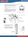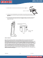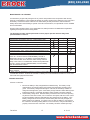
1
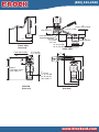
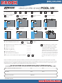
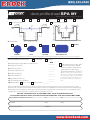
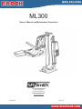
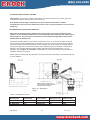
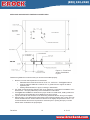
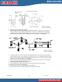
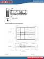
accessibility equipment
(800) 332-2360
®
s a l e s @ b r o c k e n t . c o m
New! ML300
Commercial & Institutional Pool Equipment
The ML300 is a flanged mounted pool lift that is ideal for a wide
range of pool applications. The ML300 comes standard with
our LiftOperator® Control System.
• Third party tested & verified ADA Compliant
• 300 lb/136 kg lifting capacity
• Flange mounted with four anchor bolts
• Right or left seating
• LiftOperator Intelligent Control – includes
24 Volt rechargeable battery
• Powder-coated stainless steel and aluminum construction
ML30 0 and multiLif t Comparison
Model No.
Description
Shipping Wt.
L
W
H
575-3000
ML300
190 Lbs.
56”
23”
23”
575-3000N
ML300, no anchor
190 Lbs.
56”
23”
23”
575-3005
ML300 with armrest
190 Lbs.
56”
23”
23”
575-3005N
ML300 with armrest, no anchor
190 Lbs.
56”
23”
23”
FEATURES
ML300
multiLift™
Weight Capacity
300 lbs.
350 lbs.
3rd Party Verified
ADA Compliant
YES
YES
Arm Rests
YES
YES
• 170-1000 Arm rests
• 500-5200 Total Cover
Total Cover Option
YES
YES
• 1001495 LiftOperator Battery
• 970-0000 Seat Saver Cover
Key Activation System
NO
YES
Folding Seat Option
NO
YES
Wheel-A-Way Option
NO
YES
Includes battery, charger, battery console cover, water resistant hand control, footrest, seat belt assembly and
retrofit anchor jig.
Accessories
A completed Deck Profile form is required
with your pool lift order.
New Construction Guidelines
New Construction Jig
500-5000A
Scenario
Pool Lift
Anchor Jig
Order pool lift
and new construction
jig at same time
575-3000
500-5000 (no anchors)
Order new
construction jig
ahead of pool lift
575-3000N
500-5000A (comes with anchors)
www.srsmith.com / 800.824.4387
Copyright © 2013, S.R.Smith, LLC. All rights reserved.
For the latest version of this document, see srsmith.com
www.brockent.com
(800) 332-2360
®
s a l e s @ b r o c k e n t . c o m
Commercial & Institutional Pool Equipment
42"
8"
Deck to water height
(max depth)
1.25" @ 17"SB
17"
ADA 1009.2.4
14"
Front bolt location
Set back (SB)
17.0" max
12.5" min
37"
54"
13" @ max SB
18" @ min SB
FRONT VIEW
(Retracted)
Front bolt location
18"
ADA 1009.2.8
RIGHT VIEW
17" max SB
12.5" min SB
17"
36"
12"
48" Req'd.
Clear deck space
ADA 1009.2.3
54"
42"
CL to seat
21" @ max SB
16" @ min SB
ADA 1009.2.2
18"
32"
49"
TOP VIEW
(Retracted)
TOP VIEW
(Extended)
www.brockent.com
(800) 332-2360
®
s a l e s @ b r o c k e n t . c o m
Commercial & Institutional Pool Equipment
deck profile sheet POOL lift*
*Deck profile sheet must accompany your pool lift order
1. Preferred Lift:
PAL
PAL2
Splash!
Splash! 300
aXs
multiLift
ML300
2. Gutter Configuration:
Fully recessed
gutter
C
A
C
B
A
A
D
D
Standard
backyard pool
Rollout gutter
A
A
Bull Nose Coping
Partially recessed
gutter
Fully recessed gutter
w /parapet
A
D
D
E
Florida Rollout w/curb
Flush gutter and deck
w/ or w/o bullnose
D
B
A
D
C
B
If none of the images above match your gutter configuration, please draw the shape on a separate piece of paper and attach.
3. Deck Material (check one):
Concrete
POOL
4. Distance from pool deck to water line (A): ________
5. Height of curb (B):
________
6. Width of curb (C):
________
7. Width of gutter (D):
________
8. Bull Nose Radius (E):
________
9. Decorative stone setback:
________
10. Is your pool located on the ground level?
Pavers
Yes
Check this box to confirm that
you have checked to make
sure the location of the lift will
meet the ADA Clear Deck
Space Requirement (1009.2.3):
No
“On the side of the seat opposite the water, a
clear deck space shall be provided parallel with
the seat. The space shall be 36” wide minimum
and shall extend forward 48” minimum from a
line located 12” behind the rear edge of the
seat.“
Note: Pool lifts are application specific. Please provide accurate measurements for your pool in the space provided.
S.R.Smith will confirm that the lift selected will meet the location and installation requirements based on the ADA Design
Standards (2010) or suggest an alternative lift that will meet the requirements. S.R.Smith bears no responsibility due to
misapplication of a lift without a completed Deck Profile Sheet on record.
Fax this completed form to 503.266.4334, email to [email protected],
or complete the form online at www.srsmith.com/liftprofile. Call toll free 800.824.4387
Name of Distributor Lift Will Be Purchased From
City
State
Your Name
Email
Phone
Property or Project Name
PO Number
S.R.Smith Use Only
APPROVAL#
SPLASH
PAL
SPLASH HI/LO
PAL HI/LO
SPLASH ER
PAL2
www.brockent.com
SPLASH SPA
PAL SPA
SPLASH ER HI/LO
(800) 332-2360
®
s a l e s @ b r o c k e n t . c o m
Commercial & Institutional Pool Equipment
deck profile sheet SPA lift*
*Deck profile sheet must accompany your spa lift order
1. Preferred Lift:
PAL
PAL2
Splash!
Splash! 300
In-Ground Spa
aXs
multiLift
ML300
Above Ground Spa
2. Spa Shape
OTHER*
ROUND
OVAL
SQUARE
RECTANGULAR
*If none of the images above match your gutter configuration, please draw the shape on a separate piece of paper and attach.
3. Deck Material (check one):
Concrete
Pavers
SPA
________
4. Distance from spa deck to water line (A):
5. Height of curb (B):
________
6. Width of curb (C):
________
7. Width of spa floor (D):
________
8. Depth of seat (E):
________
9. Width of seat (F):
________
10. Spa seat to floor (G):
________
11. Decorative stone setback:
________
12.Spa location:
Floor Level
Check this box to confirm that
you have checked to make
sure the location of the lift will
meet the ADA Clear Deck
Space Requirement (1009.2.3):
“On the side of the seat opposite the water, a
clear deck space shall be provided parallel with
the seat. The space shall be 36” wide minimum
and shall extend forward 48” minimum from a
line located 12” behind the rear edge of the
seat.“
Story Level # ________
Note: Pool lifts are application specific. Please provide accurate measurements for your pool in the space provided.
S.R.Smith will confirm that the lift selected will meet the location and installation requirements based on the ADA Design
Standards (2010) or suggest an alternative lift that will meet the requirements. S.R.Smith bears no responsibility due to
misapplication of a lift without a completed Deck Profile Sheet on record.
Fax this completed form to 503.266.4334, email to [email protected],
or complete the form online at www.srsmith.com/liftprofile. Call toll free 800.824.4387
Name of Distributor Lift Will Be Purchased From
City
State
Your Name
Email
Phone
Property or Project Name
PO Number
S.R.Smith Use Only
APPROVAL#
SPLASH
SPLASH 300
PAL
PAL HI/LO
SPLASH HI/LO
SPLASH ER
AXS
SPLASH W/ROUND POST
PAL SPA
SPLASH ER HI/LO
MULTILIFT
PAL2
SPLASH SPA
www.brockent.com
ML300
(800) 332-2360
®
s a l e s @ b r o c k e n t . c o m
Commercial & Institutional Pool Equipment
ML300
Owner’s Manual and Maintenance Procedures
1017 SW Berg Parkway
Canby, OR 97013
Phone: 503.266.2231
Toll Free: 800.824.4387
www.srsmith.com
700-9300
1
6.13.13
www.brockent.com
(800) 332-2360
®
s a l e s @ b r o c k e n t . c o m
Commercial & Institutional Pool Equipment
TABLE OF CONTENTS
DECK PROFILE SHEET CONFIRMATION ......................................................................... 3
INTRODUCTION AND SUMMARY ................................................................................... 4
USING THE ML300 ..................................................................................................... 4
PRODUCT OVERVIEW .................................................................................................. 6
COMPONENT DESCRIPTION ......................................................................................... 7
UNPACKING & ASSEMBLY INSTRUCTIONS ..................................................................... 8
USING THE ML300 ................................................................................................... 10
TRANSFERRING THE USER TO THE WATER..................................................................................... 11
POOL DECK INSTALLATION FOR THE ML300 ................................................................ 12
INSTALLING ANCHORS INTO EXISTING CONCRETE DECK ............................................................. 13
INSTALLING ANCHOR JIG INTO NEW CONCRETE DECK ................................................................. 15
STANDARD ACCESSORIES/OPTIONAL ACCESSORIES .................................................... 16
MAINTENANCE and CLEANING ................................................................................... 17
TROUBLE SHOOTING ................................................................................................ 17
LONG-TERM STORAGE .............................................................................................. 18
WARRANTY INFORMATION ........................................................................................ 19
SPECIFICATIONS ..................................................................................................... 21
1. Dimensions/Capacity ........................................................................................................................... 21
2. Actuator ............................................................................................................................................... 21
3. Battery ................................................................................................................................................. 21
4. Range of Motion Information ............................................................................................................... 21
6. Materials and Finish Information ......................................................................................................... 21
APPENDIX A: ML300 ASSEMBLY ................................................................................. 22
APPENDIX B: ML300 EXPLODED View ......................................................................... 23
APPENDIX C: ML300 CHAIR ....................................................................................... 25
APPENDIX D: ML300 Chair Right to Left Conversion ...................................................... 26
APPENDIX E: New Construction Jig ............................................................................. 29
700-9300
2
6.13.13
www.brockent.com
(800) 332-2360
®
s a l e s @ b r o c k e n t . c o m
Commercial & Institutional Pool Equipment
DECK PROFILE SHEET CONFIRMATION
Aquatic access lifts are application specific. A completed Deck Profile Sheet helps to ensure the lift
purchased for the application will work in accordance to ADA guidelines. S.R. Smith reviews all submitted
Deck Profile Sheets as a service to our customers, free of charge. Before installing the pool lift, the
installer must review and confirm the information provided on the Deck Profile Sheet. If the description of
the application does not match the installation site, a new Deck Profile Sheet must be completed and
submitted to S.R. Smith.
NOTE: FAILURE TO COMPLETE AN ACCURATE DECK PROFILE SHEET MAY RESULT IN THE
LIFT NOT MEETING ADA COMPLIANCE GUIDELINES.
To complete the Deck Profile Sheet online, visit www.srsmith.com/liftprofile, contact Customer Service at
(800) 824-4387 or email [email protected].
700-9300
3
6.13.13
www.brockent.com
(800) 332-2360
®
s a l e s @ b r o c k e n t . c o m
Commercial & Institutional Pool Equipment
READ THESE INSTRUCTIONS IN THEIR ENTIRETY BEFORE
BEGINNING INSTALLATION.
INTRODUCTION
The purpose of this document is to provide information relating to the installation, safe operation, care,
and maintenance of the ML300.
Intended Lift User
S.R. Smith’s lifts have been designed to assist individuals requiring assistance entering or exiting a
swimming pool or spa. The user must not exceed the weight limit of the product (300 lb/136 kg). It is the
responsibility of the lift owner to ensure that safety procedures are put in place and a risk assessment is
completed. Mental or physical disabilities may require assisted transfer, and the owner is responsible for
determining the number of qualified attendants to complete the poolside transfer and the number of
persons required to be in the water, ready to receive and assist the user. The correct stabilizing system
(seat belt or stability vest) must be attached to the seat and fully fastened and used during each transfer.
Our goal is to provide our customers with the most advanced and innovative designs offering exceptional
quality at affordable prices. All of our lifts meet the specifications set forth by the Access Board - ADAAG
2004. The lift system and AC powered battery charger complies with EN60601-1-2, 2007/03.
Using the ML300
Obey all User Instructions listed in the Owner’s Manual whenever using lift. Obey all Caution, Warning,
Operating Instruction(s) and Labels located on the lift whenever using. It is the responsibility of the lift
Owner to ensure that the correct safety procedures have been put in place and a risk assessment carried
out. If a User is mentally challenged or has physical disabilities these issues must be taken into account
to determine the number of persons required to complete the transfer onto the seat and the number of
persons required to be in the water, ready to receive the User. If the ML300 will be used by a disabled
person living on their own, a communication device should be installed in the area of use to call for
assistance in the event of an emergency. Only persons healthy enough for water activities should use the
ML300. Users should consult with their physician to determine if water activities are appropriate for the
User. Keep fingers and hands clear of lift arms during use.
Model / Product
No.______
Product Name
___________
S.R. Smith, LLC
PO Box 400
1017 SW Berg Parkway
Canby, Oregon 97013 USA
Phone: 503-266-2231
Fax: 503-266-4334
www.srsmith.com
Assembled in USA
SN S
24 VDC
700-9300
4
6.13.13
www.brockent.com
(800) 332-2360
®
s a l e s @ b r o c k e n t . c o m
Commercial & Institutional Pool Equipment
WARNINGS AND SAFETY SUMMARY
DANGER – FAILURE TO FOLLOW THESE WARNINGS, INSTRUCTIONS AND THE OWNER’S MANUAL MAY
RESULT IN SEROUS INJURY OR DEATH
ADA GUIDELINE SUMMARY* (USA Only)
1009.2.1 Pool Lift Location
Pool lift shall be located where the water level does not exceed 48”. If entire pool water level exceeds
48”, place pool lift where convenient.
1009.2.2 Seat Location
In the raised position, the centerline of the seat shall be located over the deck a minimum of 16” from the
edge of the pool.
1009.2.3 Clear Deck Space
On the side of the seat opposite the water; a clear deck space shall be provided parallel with the seat.
The space shall be 36” wide minimum and shall extend forward 48” minimum from a line located 12”
behind the rear edge of the seat.
1009.2.4 Seat Height
The lift shall stop at 16” – 19” measured from the deck to the top of the seat surface when in the loading
position.
1009.2.8 Submerged Depth
The lift shall submerge the seat a minimum of 18” below the stationary water level.
*Compliance with ADA is the responsibility of the pool owner. Visit www.ada.gov for complete guidelines.
700-9300
5
6.13.13
www.brockent.com
(800) 332-2360
®
s a l e s @ b r o c k e n t . c o m
Commercial & Institutional Pool Equipment
ML300 AQUATIC LIFT SYSTEM
PRODUCT OVERVIEW
The ML300 Aquatic Lift is a semi-portable lift system designed so that individuals with disabilities and
mobility impairments can have access to residential, hospitality and multiunit facility swimming pools or
spas. The ML300 is powered by a 24 volt rechargeable battery operated by a screw driven electronic
actuator that provides the lifting and lowering motions. Following all instructions in the owner’s manual,
and all product labels is necessary to achieve safe, reliable and proper performance of the lift and avoid
injury. This ensures consistent safe operation and minimizes service problems.
The ML300 has a mast height of 42 in / 106.6 cm above the deck. It is intended to be used with simple
pool gutter configurations having a deck to water distance of no more than 8 inches, see Table 1 and
Figure 10 to determine if the ML300 will work on a specific pool. The maximum weight capacity for ML300
is 300 lb/136 kg. Only persons healthy enough for water activities should use the ML300. Users should
consult with their physician to determine if water activities are appropriate for the user.
ML300 - PRODUCT COMPONENTS
ARMRESTS (OPTIONAL)
Figure 1 ML300
700-9300
6
6.13.13
www.brockent.com
(800) 332-2360
®
s a l e s @ b r o c k e n t . c o m
Commercial & Institutional Pool Equipment
COMPONENT DESCRIPTION
The lift is made up of several main components:
ML300 Assembly- Primary lift assembly, includes frame components, mounting base, and actuator. All
metal lift components are manufactured from stainless steel or aluminum and powder-coated for
additional corrosion protection. The standard ML300 seat assembly is a right mount configuration but can
be field mounted to the left side.
Plastic Protective Pad- The protective plastic pad is designed to be attached to the bottom side of the
ML300 mounting plate and act as a protective barrier to prevent damage to the ML300 base plate or the
pool deck.
Seat Assembly - The seat is manufactured from roto-molded plastic with a stainless steel frame. There
are two available forms of safety devices – the seat belt which comes standard, and the optional stability
vest. The seat has attachment points for both devices and both are easy to attach. Be sure to select the
appropriate safety device for the intended user.
•
•
It is recommended that people with limited or no body movement at or below the waist shall use
the seat belt restraint when using the lift.
It is recommended that people with limited or no body movement at or below the shoulders shall
use the optional stability vest restraint when using the lift.
The seat belt or optional stability vest must be used during each use. It is recommended that the seat be
rinsed off with fresh water between each use and cleansed daily with a disinfectant solution of 1:100
dilution of household bleach to fresh water and then rinsed with fresh water. In the event of a
contamination incident such as patient/user excreta - cleanse seat and seatbelt or stability vest
immediately with the above disinfectant solution. Do not use seatbelt or stability vest if it is damaged or
becomes worn.
The optional armrests (US only - standard on EU models) are designed for support when transferring
onto the seat. They can be rotated up out of the way during transfer. If the lift did not include the optional
arm rests they can be purchased separately and easily installed at a later date.
The lift seat assembly is designed to be used exclusively with S.R. Smith aquatic access lifts.
Footrest- The footrest is constructed of roto-molded plastic and is easily removable.
LiftOperator Control Box – LiftOperator controls all lift operations. For more information on the
control box see the LiftOperator Owner’s Manual, P/N 700-0500.
LiftOperator Battery - The battery is located on top of the control box and is removable. It should be
charged daily. Do not allow battery to fully discharge, as it will shorten battery life. Whenever battery is
removed from control box or lift is not in use it is important to connect battery to charger. This ensures
battery is fully charged and ready for use. The LED indicators on the battery can be checked to determine
the battery charge level.
Do not drop battery as it could cause the unit to fail. If battery case is cracked do not use and replace. Do
not place battery on a conductive surface. Placing battery on a conductive surface may cause a short.
Battery has contacts located on bottom of housing. During temperature extremes beyond the range of
41 F (5 C) to 104 F (40 C) remove battery and place in a controlled environment or battery life can be
shortened. For more information on the battery see the LiftOperator Owner’s Manual, P/N 700-0500.
700-9300
7
6.13.13
www.brockent.com
(800) 332-2360
®
s a l e s @ b r o c k e n t . c o m
Commercial & Institutional Pool Equipment
Hand Control – The two button unit controls lift movement. The arrows indicate
direction of movement. Control is fully waterproof and meets IP67 standards.
See Figure 2.
For complete parts breakdown see Appendix A and B
Figure 2. Hand
Control
UNPACKING & ASSEMBLY INSTRUCTIONS
REFER TO THE DIAGRAMS (Figure 1 and Appendix A) FOR PARTS IDENTIFICATION.
READ THESE INSTRUCTIONS IN THEIR ENTIRETY BEFORE
BEGINNING INSTALLATION
Prior to opening the shipping pallet, carefully inspect the external condition of the shipping
materials for any visible damage. It is important that any damage be noted on the Bill of Lading
prior to signing for the delivery. Contact either S.R. Smith or your dealer immediately to notify us
of any damage or missing parts.
Ensure mounting anchors have been installed in the correct location in the pool deck for proper
lift operation. It is recommended that the anchor be installed by a person familiar with installing
pool deck equipment.
The ML300 is shipped on a covered pallet and is mostly assembled. Position crate close to deck anchors
for easier assembly and set up.
Unpacking & Assembly Procedure for the ML300:
1.
2.
3.
4.
Carefully remove plastic covering from crate.
Carefully remove any wood bracing from crate.
Remove seat assembly and footrest and set aside for attachment.
Remove lift and plastic mounting pad from crate. Use the double sided tape on the plastic pad to
adhere the plastic pad to the bottom side of the mounting plate. Be sure that the holes in the
plastic pad are aligned with the mounting holes in the ML300 base plate.
5. Align holes in the mounting plate with deck anchors.
6. Locate the deck mounting hardware in the accessory carton and use the hardware to fasten the
ML300 to the anchors as shown in Figure 3. Tighten the bolts down until the lock washers are
fully compressed. Note: Anti-seize compound must be used on the stainless steel
mounting bolts to prevent seizing in the deck anchors.
7. Refer to pages 11-15 for deck anchor installation specifications and instructions.
Figure 3. Mounting Hardware
700-9300
8
6.13.13
www.brockent.com
(800) 332-2360
®
s a l e s @ b r o c k e n t . c o m
Commercial & Institutional Pool Equipment
8. The LiftOperator Control is pre-assembled on the ML300 (see LiftOperator Owner’s Manual for
more information). Remove the hand control from accessory
carton and unwrap. Insert plug into large socket on the
LiftOperator control box as shown in Figure 4. Make sure plug
is secure.
9. Ensure that the actuator plug is secured in the socket as
shown in Figure 4.
10. Attach battery to LiftOperator control box making sure that the
battery latch bracket locks into the slots on the control unit
mounting bracket. To remove the battery from the control unit,
pull outward on the battery handle until the battery latch
bracket clears the slots in the control unit mounting bracket,
then pull upward, see Figure 5.
Figure 4. Control Box
2
BATTERY HANDLE
CONTROL UNIT MOUNTING BRACKET
BATTERY LATCH
BRACKET
1
Figure 5. Battery
Attachment/Removal
11. Check all controls and emergency stop
button for proper operation. See LiftOperator
Owner’s Manual for details.
12. Attach seat assembly with bolt and thumbnut
in appropriate hole. Refer to Figure 10 and
Table 1 to determine the correct seat
mounting hole to use. Also see Figure 6.
Figure 6. Seat
Mounting Holes
700-9300
9
6.13.13
www.brockent.com
(800) 332-2360
®
s a l e s @ b r o c k e n t . c o m
Commercial & Institutional Pool Equipment
13. Attach footrest to seat with bolts and thumbnuts as shown in Figure 7.
Figure 7. Footrest
14. The ML300 comes standard with the seat mounted on the right side of the lift as shown
in Figure 9. The seat can be moved to the left side of the lift by following the instructions found in
Appendix D.
15. If the deck slope where the lift is mounted is causing the lift seat not to be level, the seat angle
can be adjusted by loosening the bolts shown in Figure 8, adjusting the seat to level, and
retightening the bolts.
Figure 8. Seat
Leveling
USING THE ML300
Obey all User Instructions listed in the Owners Manual whenever using lift. Obey all Caution,
Warning, Operating Instruction(s) and Labels located on the lift whenever using. It is the
responsibility of the lift Owner to ensure that the correct safety procedures have been put in place
and a risk assessment carried out. If a User is mentally challenged or has physical disabilities
these issues must be taken into account to determine the number of persons required to complete
the transfer onto the seat and the number of persons required to be in the water, ready to receive
the User. If the ML300 will be used by a disabled person living on their own, a communication
device should be installed in the area of use to call for assistance in the event of an emergency.
Only persons healthy enough for water activities should use the ML300. Users should consult
with their physician to determine if water activities are appropriate for the User. Keep fingers and
hands clear of lift arms during use.
700-9300
10
6.13.13
www.brockent.com
(800) 332-2360
®
s a l e s @ b r o c k e n t . c o m
Commercial & Institutional Pool Equipment
ML300 Transferring Diagram
Figure 9. Transferring
TRANSFERRING THE USER TO THE WATER
Once the unit is positioned for use, use the following procedure to transfer to the seat and into the water.
Only persons healthy enough for water activities should use the ML300. Users should consult with their
physician to determine if water activities are appropriate for the User:
•
•
•
•
•
•
•
•
•
•
•
•
•
Check battery level of LiftOperator to ensure charge is adequate for operation (at least 50%
charge recommended).
Use the buttons on the hand control or control unit front panel to raise the seat to the deck
loading/unloading position as shown in Figure 9.
Transfer user onto the seat, ensuring that the user’s weight is centered on seat. Armrests can be
rotated up if necessary (optional US/standard on EU models). If user has a wheelchair, keep the
wheelchair close by for easy retrieval.
Fasten Seat Belt - thread loose end of belt strap through buckle - pull tight - to close - press latch
down on belt material.
Or fasten optional Stability Vest - Position shoulder straps onto shoulders and attach straps to
clips on bottom panel of the Stability Vest - pull shoulder straps tight.
Use the hand control or control unit front panel to lower the seat into the water. The waterproof
hand control can remain connected to seat if user is operating lift.
Unfasten Seat Belt - grasp latch and lift up, pull loose end from latch.
Or unfasten optional Stability Vest - unclip shoulder straps and transfer into water.
When finished, return to the seat, ensuring user’s weight is centered on seat.
Fasten Seat Belt or optional Stability Vest.
Use the buttons on the hand control or control unit front panel to return the seat to the deck
loading/unloading position.
Unfasten Seat Belt or optional Stability Vest.
Transfer off of the seat
700-9300
11
6.13.13
www.brockent.com
(800) 332-2360
®
s a l e s @ b r o c k e n t . c o m
Commercial & Institutional Pool Equipment
IN CASE OF HAND CONTROL FAILURE
Lifting failure - In the event of a hand control failure, or if the hand control is out of reach, there are
control buttons built into the touch pad of the control box.
If the ML300 will be used by a disabled person at an unsupervised location, a reliable
communication device must be installed in the area of use to call for assistance in the event of an
emergency.
POOL DECK INSTALLATION FOR THE ML300
Ensure the anchors have been installed in the correct location in the pool deck for proper lift
operation. It is recommended that the anchor be installed by a person familiar with installing pool
deck equipment. The pool owner is responsible for ensuring that all applicable ordinances are
followed when installing the lift.
The optimal mounting distance for the deck front anchors is 12.5”/ 31.75 cm from the edge of the pool.
The front anchors can be installed up to a maximum of 17”/43.18 cm from the edge of the pool, but the
deck edge clearance decreases the farther the lift is installed from the pool edge. The setback distance
from the pool edge to the front anchor locations varies depending upon pool geometry. The ML300 is
designed to be used with simple pool edge designs with deck to water level differences of 0” to 8”
maximum. Review Figure 10 and Table 1 to determine the correct seat mounting location and anchor
installation setback for your pool.
Please contact S.R.Smith with any questions concerning deck anchor placement or if the ML300 will work
in your installation.
Figure 10. Installation
Layout
Table 1. Installation Layout
Deck to Water
Distance (D1)
0”-6”
7”
8” (Maximum)
700-9300
Max Setback
Distance (D2)
17”
14.75”
12.5”
Seat Mounting
Hole Location
Top Hole
Middle Hole
Bottom Hole
12
Height of Seat
Above Deck (D3)
18”
17”
16”
Deck Edge
Clearance (D4)
1.25”
2.25”
3.25”
6.13.13
www.brockent.com
(800) 332-2360
®
s a l e s @ b r o c k e n t . c o m
Commercial & Institutional Pool Equipment
INSTALLING ANCHORS INTO EXISTING CONCRETE DECK
Figure 11. Flush Deck
Anchor Installation
Layout
Follow these guidelines to make sure that your anchors are installed properly:
1. Minimum concrete slab requirements for the ML300:
• Slab dimensions should be at least 42” X 60” X 4”, reinforced. See Figure 11 above.
• Anchors shall be installed at a minimum of 4” or greater from the edge of the slab or
expansion joint.
• Existing slab shall exhibit no signs of cracking or deterioration.
2. S.R. Smith recommends using Simpson SET epoxy adhesives or equivalent for installation of the
deck anchors. Use epoxy adhesives per the manufacturer’s instructions.
3. Use Figure 10 and Table 1 to determine the proper location to install the lift, making certain that
the front anchors are located the correct distance from the pool edge.
4. Layout and mark the hole locations on the deck using the ML300 Anchor Set Jig as a template.
5. Drill four holes 1.125” diameter and 3.625” deep in the locations marked in step 2. Note: The hole
that the bondable anchor will be inserted into will need to be slightly deeper than the others. It is
recommended that the anchors are placed into each hole prior to pouring the epoxy to ensure
that the holes are drilled to the proper depth.
700-9300
13
6.13.13
www.brockent.com
(800) 332-2360
®
s a l e s @ b r o c k e n t . c o m
Commercial & Institutional Pool Equipment
Figure 12. Deck
Anchor Installation
6. Clean all dust and debris from the holes.
7. Bond at least one of the flush deck anchors per local codes. Contact your local Authority
having jurisdiction for the bonding requirements in your area. A threaded hole for attaching a
bonding screw is provided on bottom side of one of the deck anchors. Use the screw provided
with the deck anchor kit to attach the bonding wire to the deck anchor. See Figure 13.
Figure 13. Deck
Anchor Installation
8. The ML300 Anchor Jig must be used to ensure that the anchors are held in the correct position
until the epoxy is cured. To use the Anchor Jig, place the ½”-13 X 2” Hex Bolts through the tubes
in the Anchor Jig and thread the bolts into the anchors until the top surface of the anchors contact
the bottom of the Anchor Jig tubes. See Figure 13.
9. Blocks can be used as spacers between the deck surface and the Anchor Jig to ensure that the
tops of the anchors are flush with the deck surface.
10. Fill holes approximately half full with epoxy.
11. Insert deck anchors, making sure that the anchors are flush with the top of the deck.
12. Remove any excess epoxy immediately.
13. Allow the epoxy to cure per the manufacturer’s instructions.
14. Once the epoxy has cured, install the lift per the installation instructions.
700-9300
14
6.13.13
www.brockent.com
(800) 332-2360
®
s a l e s @ b r o c k e n t . c o m
Commercial & Institutional Pool Equipment
Figure 14. Deck
Anchor Bonding
INSTALLING ANCHOR JIG INTO NEW CONCRETE DECK
Figure 15. Deck
Anchor Jig Installation
700-9300
15
6.13.13
www.brockent.com
(800) 332-2360
®
s a l e s @ b r o c k e n t . c o m
Commercial & Institutional Pool Equipment
Follow these guidelines to make sure that your anchor jig is installed properly:
1. Minimum concrete slab requirements for the ML300:
• Slab dimensions should be at least 42” X 60” X 4”, see Figure 15 above.
• Anchors shall be installed at a minimum of 4” or greater from the edge of the slab or
expansion joint.
• Normal weight of concrete = 150 lbs/ft^3
• Concrete minimum compressive strength at 28 days to be F’c =2500 psi.
• Reinforcing bars shall conform to ASTM A615 Grade 60, deformed.
2. Use Figure 10 and Table 1 to determine the proper location to install the lift, making certain that
the front anchors are located the correct distance from the pool edge.
3. Assemble the deck anchors to the anchor jig as described in Appendix E.
4. Install the anchor jig and reinforcing rods per Figure 15.
5. Use the bonding lug provided on the anchor jig to attach the bonding wire per local codes.
Contact your local Authority having jurisdiction for the bonding requirements in your area.
6. Make sure that the top of the anchors are flush with the top surface of the slab.
7. Allow concrete to cure per manufacturer’s instructions.
8. Once the concrete has cured, install the lift per the installation instructions.
STANDARD ACCESSORIES/OPTIONAL ACCESSORIES
The following items are included with all pool lift models:
.
• Seat Belt Assembly - Nylon water-resistant belt for added security.
• Battery/Charger – 24-volt rechargeable battery.
Optional accessories may be purchased for your ML300 lift through your Authorized Reseller. The
following accessories are available:
Console/Battery Cover – P/N 910-1000: Protects battery and control unit from exposure to moisture
Stability Vest - P/N 900-2000: Five point restraint for individuals who need higher degree of stability than
provided with standard seat belt.
Total Cover - P/N 575-5100: Made of weather resistant nylon material to keep unit protected from
elements when not in use.
Arm Rest Assembly – P/N 170-1000: Powder coated stainless steel arm rests for increased sense of
security. Reference Appendix C for details.
Seat Pad - P/N 890-1000: Waterproof seat pad designed to enhance comfort during transfer.
Deck Anchor Kit P/N 300-6700A – Includes 4 flush deck anchors.
New Construction Anchor Jig P/N 500-5000 – Includes anchor jig, and hardware minus the flush deck
anchors. See anchor jig assembly info Appendix E.
Lift Operator Single Channel Controller with Activation Key P/N 1001545 – Activation key can be
used to prevent unauthorized use of the lift. For more information on the control unit with activation
key see the LiftOperator Owner’s Manual, P/N 700-0500.
700-9300
16
6.13.13
www.brockent.com
(800) 332-2360
®
s a l e s @ b r o c k e n t . c o m
Commercial & Institutional Pool Equipment
MAINTENANCE and CLEANING
A maintenance program will prolong the life of your lift. Keep all electronic components clean and dry.
Keep the console/battery cover installed at all times to prevent moisture from collecting on the control box
and battery. Excessive moisture collection can affect battery and lift performance and could lead to
battery failure and/or the lift failing to operate. If the lift is used outdoors, an optional full cover is available
and recommended.
Owners of lifts should be aware of any applicable local, state/provincial or federal/national regulations
regarding the inspection and or testing of lifts.
The following schedule shall be performed to insure proper operation with the Daily items
performed before each use:
Maintenance Performed
Check battery level before each use / Charge battery daily
Daily
Weekly
Monthly
Wipe Control Box and battery connection with a clean dry rag
Examine lift for any damage, loose or missing hardware
Test for normal operation
Make sure all cable connections are properly secured
Inspect lift frame, mast, support arm and seat assembly for rust
Cleansing Performed – after each use
Rinse seat and seatbelt/stability vest with fresh water between
each use - Cleanse seat and seatbelt/stability vest with a
disinfectant solution of 1:100 dilution of household bleach to
fresh water and then rinse with fresh water and dry entire lift
daily. In the event of a contamination incident such patient/user
excreta - cleanse seat and seatbelt/stability vest immediately
with the disinfectant solution*
Cleanse all battery connections with a nylon scouring pad
Cleanse all metallic surfaces with a cleaner wax to maintain the
finish of the lift
* When using the disinfection solution avoid direct contact with the skin and eyes. In the event of a
contamination incident - immerse the seat belt or stability vest in the disinfection solution for 10 min. and
then rinse thoroughly with fresh water.
TROUBLE SHOOTING
Lift does not function:
1. Be sure the battery is fully charged before troubleshooting. The battery is fully
charged when the charge indicator LED located near the battery charging port is
green. If the battery charge indicator light is solid red, let the battery continue to
charge until the light turns green. If the battery charge indicator LED is flashing red, it
indicates that there is a fault with the battery and the battery should be replaced.
2. Check battery charge level. With the battery connected to the control box, pressing
any button on the hand control, or the control box front panel, will turn on the control
box and the battery indicator LEDs will show the charge level of the battery. If the
Battery charge level is less than 25% and the battery has been fully charged, the
battery needs to be replaced. If no lights come on after the battery is connected to
the control box and after pushing buttons on the control box, verify that the battery is
properly connected to the control box. If the battery has been checked per step 1,
700-9300
17
6.13.13
www.brockent.com
(800) 332-2360
®
s a l e s @ b r o c k e n t . c o m
Commercial & Institutional Pool Equipment
then the issue is likely with the control box, and the control box will need to be
replaced.
Lift will not raise and lower when using the hand control:
1.
2.
3.
4.
Check hand control connection to control box. Be sure plug is pushed in all the way.
Check hand control connection to control box for damaged pins.
Check connection cable for damage.
Use the buttons on the front panel of the control box to raise and lower the lift. If the
lift raises and lowers when using the buttons on the front of the control box, the hand
control should be replaced.
If none of the above steps work in getting the lift to function, call S.R. Smith for assistance.
LONG-TERM STORAGE
When storing the lift for an extended period of time:
•
•
•
Wash seat with disinfectant solution and then rinse with fresh water and dry entire lift
Keep the battery on the charger in a dry temperature controlled area
Cover unit and store in a dry location away from pool chemicals
Questions/Comments - Contact us at 800.824.4387 or 503-266-2231 or [email protected]. For
information regarding Authorized Resellers worldwide visit www.srsmith.com
700-9300
18
6.13.13
www.brockent.com
(800) 332-2360
®
s a l e s @ b r o c k e n t . c o m
Commercial & Institutional Pool Equipment
WARRANTY INFORMATION
S.R. Smith, LLC warrants to the original retail purchaser that products manufactured by S.R. Smith, when properly assembled and
installed in accordance with S.R. Smith’s assembly and installation instructions, and properly used and maintained, shall be free
from defects in material and workmanship for a period of three (3) years from the date of original manufacture except for the
following items: WetDek™ (1 year) and PoolSonix™ (2 years). The original retail purchaser must follow the procedure set forth
below when submitting a warranty claim. S.R. Smith will repair or replace, at its option, the product, and return it to the owner freight
prepaid. Determination of repair or replacement shall be solely at the discretion of S.R. Smith. Aquatic lift systems, components
and batteries have a separate warranty, set forth below.
All Aquatic Lifting Systems have a three (3) year warranty on the frame, excluding the powder coated paint finish, which may
become scratched with normal use. All electronic and motor components, with the exception of batteries, have a full two (2) year
warranty. Within the warranty period, S.R.Smith will repair or replace any item deemed to be found defective. Lift batteries come
with a one-year pro-rated warranty. During the first 90 days of ownership, batteries will be covered 100%. If a battery failure occurs
between day 91 and day 365, batteries are covered at 50% of the original cost. Normal maintenance and care of the unit, including
charging of the battery when not in use is recommended. Do not store the unit, battery or components near or around chemicals.
The warranty is non-transferable and is subject to the following terms and conditions (View complete S.R.Smith Terms &
Conditions):
S.R. Smith shall not be responsible for the cost of removal or replacement of any defective S.R. Smith product, nor for any other
expenses or for damages which might be incurred in such removal and replacement.
This warranty specifically excludes fading of materials, microbiological staining of diving boards or pool slides and rust or
corrosion of any metallic products or parts. Refer to S.R. Smith care and maintenance instructions for regular
maintenance and cleaning of S.R. Smith Products. Maintenance instructions can be found at www.srsmith.com/care.php.
This warranty relates only to defects in materials and workmanship and does not include damage or failure resulting from other
causes, including, but not limited to Acts of God, misuse or abuse, accident or negligence, fire, improper assembly or installation,
chipping or flaking of powder or vinyl coatings, or ice damage. Damage induced by the improper use of chemicals is not covered by
this warranty. In the event that products are altered or repaired by anyone without the prior written approval of S.R. Smith, all
warranties are void.
IMPORTANT: WEIGHT LIMIT ON DIVING BOARDS, JUMP BOARDS, STANDS, SLIDES, LADDERS AND LADDER STEPS
SHALL BE NOT MORE THAN 250 POUNDS. EXCEPTIONS: FRONTIER IV BOARD AND BASE NOT MORE THAN 400 POUNDS.
TURBOTWISTER AND TYPHOON SLIDES NOT MORE THAN 275 POUNDS. CYCLONE SLIDE NOT MORE THAN 175
POUNDS. VORTEX SLIDES NOT MORE THAN 325 POUNDS.
S.R. Smith shall not be liable for any consequential, special or incidental damages, including, but not limited to any damages for loss
of use of pools or injury to person or property, and any claims therefore are hereby specifically disclaimed and excluded. Some
states do not allow the exclusion or limitation of incidental, special or consequential damages, so the above limitation or exclusion
may not apply to you. This warranty gives you specific legal rights and you may also have other rights, which may vary from state to
state. The warranty is extended to, and enforceable only by the original retail purchaser.
If any S.R. Smith products fail during the warranty period as a result of a defect in material or workmanship covered by this
warranty, the original retail purchaser must notify S.R. Smith via www.srsmith.com/warranty.php. This notice from the original retail
purchaser must contain all pertinent product information as outlined in the warranty claim form. S.R. Smith will determine if the
product is to be returned to the factory or will ask that ( 1 ) the defective area and ( 2 ) the part of the product stamped with the serial
number be removed and returned. Product pieces must be cleaned and returned freight prepaid to S.R. Smith’s facility at either
1017 SW Berg Parkway, Canby, OR 97013 or 105 Challenger Drive, Portland, TN 37418 as determined by S.R.Smith.
THE WARRANTY SET FORTH HEREIN IS IN LIEU OF ALL OTHER WARRANTIES, EXPRESSED OR IMPLIED, WHICH ARE
HEREBY DISCLAIMED AND EXCLUDED, INCLUDING WITHOUT LIMITATION ANY WARRANTY OF MERCHANTABILITY OR
FITNESS FOR A PARTICULAR PURPOSE OR USE.
THE SOLE AND EXCLUSIVE REMEDIES FOR BREACH OF ANY AND ALL WARRANTIES WITH RESPECT TO THE
PRODUCTS SHALL BE LIMITED TO REPAIR OR REPLACEMENT AT S.R. SMITH’S DESIGNATED FACTORY OR IN PLACE AT
S.R. SMITH’S OPTION. IN NO EVENT SHALL S.R. SMITH’S LIABILITY EXCEED THE ENTIRE AMOUNT PAID TO S.R. SMITH
BY THE ORIGINAL PURCHASER FOR THE FAILED OR DEFECTIVE PRODUCT.
IN NO EVENT SHALL S.R. SMITH BE LIABLE FOR ANY INCIDENTAL, CONSEQUENTIAL, SPECIAL, INDIRECT, PUNITIVE OR
EXEMPLARY DAMAGES OR LOST PROFITS FROM ANY BREACH OF THIS LIMITED WARRANTY OR OTHERWISE.
700-9300
19
6.13.13
www.brockent.com
(800) 332-2360
®
s a l e s @ b r o c k e n t . c o m
Commercial & Institutional Pool Equipment
No representative of S.R. Smith, nor any of its agents, distributors or dealers has any authority to alter in any manner the terms of
this warranty and S.R. Smith is not responsible for any undertaking, representation or warranty made by any other person beyond
the warranty expressly set forth in this warranty.
Warranty Procedures
The S.R. Smith warranty becomes effective on the date of manufacture.
To initiate a warranty replacement, Please follow the process outlined below.
1. Take photos of the damaged product.
a) The photo must include the entire unit (i.e. board and stand or slide from a distance).
b) Also include one photo or more of the damaged area.
2. Remove the serial # sticker from the product.
a) S.R. Smith provides a serial # for every board, stand, slide and rail product we produce. The
sticker with the serial number for our boards, stands and slides is a silver, 1" long rectangular
sticker found on the side or bottom of the item. The serial # sticker for our rail products is clear
and 2" long. It will be found on the inside of the topmost curve.
3. Attach the photos and the serial # sticker to a written request for replacement under the
S.R. Smith warranty. Please include the following information:
a) Product name and description. (i.e.:. board length/color, curve direction of slide, etc.)
b) Date of purchase and/or date of installation.
c) Description of damage.
d) Shipping address with a contact name and phone number.
4. Return to us by mail the photos, serial # sticker and your written request to:
S.R. Smith, LLC
PO Box 400
1017 SW Berg Pkwy
Canby, OR 97013
Attn: Warranty Specialist
**Please Note: Missing information will result in a processing delay and possibly denial of your claim.
Should you have any questions regarding this process, please contact
S.R. Smith's Warranty specialist at 800.824.4387 or email [email protected]
Batteries
All batteries are inspected prior to shipment and should be free from defect. See warranty policy
regarding battery replacement due to defect. Batteries have a normal lifespan of between 2-3 years,
depending on use and care.
Battery should be charged daily. Do not allow battery to fully discharge, as it will shorten battery life.
Whenever battery is removed from Control Box or lift is not in use it is important to connect battery to
charger. This ensures battery is fully charged and ready for use.
Do not drop the battery, as it could cause the unit to fail. If the battery case is cracked do not use and
replace. Battery has contacts located on the bottom of the housing. Do not place on a conductive surface
that can cause a short. During temperature extremes beyond the range of 41 F (5 C) to 104 F (40 C)
remove battery and place in a controlled environment.
Keep the console/battery cover installed at all times to prevent moisture from collecting on the control box
and battery. Excessive moisture collection can affect battery and lift performance and could lead to
battery failure and/or the lift failing to operate.
700-9300
20
6.13.13
www.brockent.com
(800) 332-2360
®
s a l e s @ b r o c k e n t . c o m
Commercial & Institutional Pool Equipment
BATTERY DISPOSAL
The battery is recyclable and shall be disposed of in accordance with applicable local, state/provincial or
federal/national regulations.
SPECIFICATIONS
ML300
1. Dimensions/Capacity
Height
Overall Length-extended
Storage Length-w/o chair
Unit Weight-inc. chair
Unit Weight-w/o chair
Power
Battery Life
Lifting Capacity
Anchor Reaction Load:
Vertical
Torque
42“/106.7cm
62”/157.5 cm
18”/ 45.72cm
118 lb/ 53.52 kg
88 lb/ 39.9 kg
24v DC
30 cycles (approx.)
300 lb/ 136 kg
467 lb/ 211.8 kg
1158 ft lb/ 1570 Nm
2. Actuator
Type
Maximum Thrust
Voltage
Maximum Amp Draw
Maximum Speed
Screw Type Mechanical Actuator
1680 lb/7472N
24v DC
9
0.59 inch/sec./1.49cm/sec.
3. Battery
Power
Temperature Range
24 VDC, IP65 Gel Lead Acid
41 F (5 C) to 104 F (40 C)
4. Range of Motion Information
Vertical Travel
5. Noise
42”/106.7 cm
Noise level below 50 dB (A), measured according
to DS/EN ISO 3746”
6. Materials and Finish Information
Frame
Arms
Mast
Seat Assembly
Covers
700-9300
Powder Coated Stainless Steel
Powder Coated Aluminum
Powder Coated Stainless Steel
Seat: Roto-Molded Plastic
Frame: Powder Coated Stainless Steel
Urethane coated nylon
21
6.13.13
www.brockent.com
(800) 332-2360
®
s a l e s @ b r o c k e n t . c o m
Commercial & Institutional Pool Equipment
APPENDIX A: ML300 ASSEMBLY
*500-5000
700-9300
NEW CONSTRUCTION JIG SOLD SEPARATELY
22
6.13.13
www.brockent.com
(800) 332-2360
®
s a l e s @ b r o c k e n t . c o m
Commercial & Institutional Pool Equipment
APPENDIX B: ML300 EXPLODED View
700-9300
23
6.13.13
www.brockent.com
(800) 332-2360
®
s a l e s @ b r o c k e n t . c o m
Commercial & Institutional Pool Equipment
ITEM
NO.
PART
NUMBER
Default
/ QTY.
DESCRIPTION
1
14550
BASE ASSEMBLY
2
14770A
ACTUATOR ARM ASSY W/ BUSHINGS
1
3
14660A
ACTUATOR CAGE ASSY W/ BUSHINGS
1
4
14990
CONTOL AXLE ASSY
1
5
14880A
SEAT ARM ASSY W/ BUSHINGS
1
6
14440A
SUPPORT ARM W/ BUSHINGS
1
7
800-0119
THRST BSHG .375"ID X .75"OD X .0625"LG
1
8
800-0106
THRST BSHG .375"ID X .75"OD X .125"LG
3
9
05-32-111
3/8" NYLON PROTECTIVE WASHER
9
10
800-2024
3/8 FLAT WASHER SS
7
11
800-0111
BOLT 3/8" SHLDER DIA, 3/4" L SHLDER, 5/16"-18 THRD, S/S
2
12
800-0140
LOCK NUT, 5/16-18, HEX S/S
2
13
100-7000
600MM ACTUATOR
1
15
800-0146
WASHER, .406"ID X .75" OD X (.08-.11" THICK), S/S
2
16
800-0117
HHCS .375" x 1.625" S/S
2
17
800-2026
3_8-16 x 2 1_4 Hex Bolt
1
18
800-0112
3/8 LOCK NUT S/S
4
19
800-0103
1/4" SET SCREW
1
20
800-0116
BOLT, SHOULDER 3/8" DIA X 1" LG X 5/16-18" THRD S/S
1
21
800-0120
5/16”-18 JAM LOCK NUT S/S
1
22
800-0121
THRST BUSH .75"ID x 1.25"OD x .0625" LG
1
23
800-0142
Stud, 5/8"-11 Threaded Both Ends X 6.875 Long
1
24
800-0126
SHIM S/S .75"ID X 1.125"OD X .062LG"
1
25
800-0127
Push-on Round FDA Cap Fits 3/8" OD, 1" Inside Height
1
26
800-0128
BLK FOAM, 1.5"WD x 3.5"LG CUT
1
27
1001498
LIFT OPERATOR MOUNT PLATE
1
28
1001499
CONTROLLER ASSEMBLY, 2 BUTTON
1
29
800-2014
10-24 PAN HEAD PHILLIPS BOLT SS 18-8
4
30
1001494
SCREW, #10-24 x 3/8" PAN HD TORX
1
31
800-0143
NUT, JAM (THIN), NYLON LOCK 3/4"-10, S/S
1
32
05-631
5/8" X 1-3/4" NYLON WASHER
2
33
800-0145
WASHER, 5/8"ID X 1 1/2" OD X 1/16" THICK, S/S
2
34
800-0144
NUT, NYLON LOCK, 5/8"-11, S/S
2
35
05-14-102
5/16” FLAT WASHER S/S
2
700-9300
1
24
6.13.13
www.brockent.com
(800) 332-2360
®
s a l e s @ b r o c k e n t . c o m
Commercial & Institutional Pool Equipment
APPENDIX C: ML300 CHAIR
FOOT RESTS
1.
ATTACH THE FOOTREST USING THE THUMBSCREWS AND 2 ¾” LONG HEX BOLT
•
(800-2042 AND 800-2039)
*ARMRESTS (HARDWARE PROVIDED WITH ARMREST CHAIR 160-5005)
1.
2.
3.
4.
700-9300
POSITION THE ARM OVER THE THREE HOLES REAR OF THE BACKREST THAT MATCH THAT OF
THE SEAT ARM. INSURE THE TUBE OF THE SEAT ARM IS CRADLED IN THE PLASTIC SEAT BACK.
•
(160-1800 TO 170-1000-L or –R)
ATTACH THE ARMRESTS USING THE 5/16” THREAD X ½” LONG HEX BOLT AND IT’S 5/16”
NYLON WASHER TO THE 1.5” DIAMETER SEAT FRAME TUBE. DO NOT TIGHTEN COMPLETELY.
•
(800-2019 with AC2002)
MOVE THE ARMREST AS NEEDED TO ALIGN THE ¼”-20 THREAD X 1 ¼” PHILLIPS SCREWS
THROUGH THE ARMREST TUBE AND INTO THE PLASTIC SEAT BACK’S BRASS INSERTS.
ONCE ALL SCREWS ARE STARTED, PROCEED WITH FULLY TIGHTENING ALL OF THE SCREWS
575-3000
ML300 without ARMREST
575-3005
ML300 with ARMREST
25
*comes with seat 160-5005
6.13.13
www.brockent.com
(800) 332-2360
®
s a l e s @ b r o c k e n t . c o m
Commercial & Institutional Pool Equipment
APPENDIX D: ML300 Chair Right to Left Conversion
CONTROL AXLE
SEAT ARM
4.
1.
2.
SUPPORT
ARM
3.
ACTUATOR
ARM
Note: Appendix B can be used as a reference for hardware order of assembly.
The following directions describe the process for moving the ML300 seat from the right (standard)
mounting configuration to left mounting configuration.
1. Remove the two lock nuts from the top pivot assembly.
2. Remove the ¾” lock nut from the end of the Control Axle.
3. Slide the Seat Arm off of the ¾” Control Axle.
4. Remove the 3/8” hex bolts from the Support Arm and Control Axle.
5. Next, carefully rotate the Support Arm out of the way.
SUPPORT
ARM
Base
Assembly
6.
8.
700-9300
26
7.
6.13.13
www.brockent.com
(800) 332-2360
®
s a l e s @ b r o c k e n t . c o m
Commercial & Institutional Pool Equipment
6. Remove the 3/8” lock nut that secures the bottom of the Support Arm to the Base Assembly.
7. Slide the Support arm off the stud and set aside.
8. Remove the 1/8” thick thrust bushing from the stud.
Control
Axle
Seat Arm
10.
11.
SUPPORT
ARM
9.
12.
Actuator
ARM
9. Insert the ¾” Control Axle into the Actuator Arm from the opposite side of the lift, and slide the Seat
Arm back over the axle from the other side.
10. Align the holes for the 3/8” hardware and replace the 3/8” Hex bolts, with washer and nylon washer
back through the components as pictured above. Note that the 1/16” Bronze Thrust Bushing is to be
placed between the Support Arm and Control Axle.
11. Use the 3/8” hex nuts to secure the bolts installed in step 10.
12. Secure the control Axle using the Bronze Thrust Bushing, S/S washer, and ¾” Lock Nut.
13.
13. Tighten the Hex Bolt passing through the Support Arm up until snug, then and additional ¼” turn. The
other Hex Bolt can be tightened until the Seat Arm and Control Axle are secured tightly together.
700-9300
27
6.13.13
www.brockent.com
(800) 332-2360
®
s a l e s @ b r o c k e n t . c o m
Commercial & Institutional Pool Equipment
14
15. Remove the White Plastic Cap from the stud on the opposite side of the lift and replace it on the
stud from which the Support Arm was removed. Attach the tension arm onto stud with the 1/8”
Thrust Bushing placed between the base bracket and Support Arm. Secure the Support Arm
using the nylon washer, stainless steel washer and lock nut.
16
15
15. Switch the control box to the opposite side by removing the torx head screw and detaching the control
box from the mounting bracket. This allows access to the Phillips screws holding the mounting bracket to
the lift frame.
16. Remove both the Phillips screws and replace the mounting bracket to the opposite side of the frame
with the Phillips screws installed on the opposite side of the frame. Replace the Phillips screws where the
mounting bracket was removed.
700-9300
28
6.13.13
www.brockent.com
(800) 332-2360
®
s a l e s @ b r o c k e n t . c o m
Commercial & Institutional Pool Equipment
17
17. With the Control Box secure in place, test the unit by attaching the battery and making sure the lift
functions correctly. Check all hardware and make sure it is tightened securely before using the lift.
APPENDIX E: New Construction Jig
NEW CONSTRUCTION ANCHOR JIG
WHEN ASSEMBLING THE FLUSH DECK ANCHORS TO THE NEW CONSTRUCTION JIG,
MAKE SURE THAT THE DISTANCE BETWEEN THE TOP SUFACE OF THE JIG AND THE TOP
OF EACH ANCHOR IS 2.5”, AS SHOWN IN THE DIAGRAM ABOVE.
* FLUSH DECK ANCHORS (300-6700) SOLD SEPARATE *KIT NUMBER 300-6700A (QTY 4)
700-9300
29
6.13.13
www.brockent.com