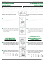
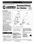
1
R-50 Series Rotor
Installation Instructions
CONTENTS ▼
General Information
▼ ESPAÑOL
pg.
1
pág.
Información General
Tips on Installation
2
Sugerencias para la instalación
Adjustable Bypass
2
Control de flujo
“Quick Change” Nozzles
4
Cambio de la boquilla
Part Circle Adjustment
5
Ajuste del arco–círculo parcial
Full Circle Adjustment
6
Ajuste del arco–círculo completo
▲ CONTENIDO
ENGLISH ▼
GENERAL INFORMATION
T
he R-50 can be set to full circle (360º) or part circle operation
(25º–350º) without the use of tools. The sprinklers are factory preset to approximately 180º or half circle.
INFORMAClON GENERAL
E
l arco del aspersor R-50 puede ser ajustado manualmente de
círculo completo (360º) o de círculo parcial (25º a 350º). Los
aspersores R-50 son despachados de fábrica con su arco prefijado
de aproximadamente 180º, o medio círculo.
The left side of the arc is fixed. This fixed position on
the sprinkler can be identified by finding double ribs
on the outside of the body (see illustration #1).
Because the left side of the arc is fixed, it is necessary
to install the sprinkler taking into consideration its
position with respect to the boundaries of area to be
watered. It is possible to turn the entire sprinkler, once
installed on its fitting, to modify the position of the
double ribs and thereby affect the left side of the arc.
El lado izquierdo del arco es fijo. Puede identificarse la
posición del límite izquierdo del arco (el “stop”) localizando las varillas dobles sobresalientes en la parte
superior del cuerpo del aspersor (vea la ilustración #1).
1
Como el límite izquierdo del arco es fijo, es necesario
instalar el aspersor tomando en cuenta su posición
respecto al borde izquierdo del area a regar. Es posible
girar el aspersor completo, una vez instalado, para
modificar la posición de las varillas dobles, así
moviendo el lado izquierdo del arco.
Es posible girar la cabeza del aspersor manualmente
cuando está en operación para chequear el arco que
Usted ha ajustado.
The nozzle turret can be turned manually during
operation to check the arc you have set.
2
R-50 Installation Instructions
R-50 Instrucciones para la Instalación
A unit set to full is a true, not a
reversing full circle, and it operates
in only one direction for superior irrigation efficiency. (See pages 5 and
6 to set the arc.)
Un aspersor R-50 con su arco prefijado en círculo completo gira en una
sola dirección, sin que se devuelva su
chorro, para una mayor eficiencia
del riego. (Vea las páginas 5 y 6 para
ajustar el arco.)
3
The vandal collar located on the riser
shaft must be spread and pushed
down to allow adjustments to the arc. When properly pushed down,
it will return to its track automatically when it pops down if you
forget to do so.
Cuando se ajusta el arco, primero es
necesario abrir el collar protector
(“vandal collar”) y empujarlo hacia abajo en el elevador. No lo
quite. De esta manera, el collar se devolverá a su posición original
automáticamente cuando el aspersor se retracte, aunque Usted
haya olvidado hacerlo.
TIPS ON INSTALLATION
SUGERENCIAS PARA LA INSTALAClON
As with all sprinkler products, you must flush the system
Al igual que todos los productos de riego, se debe limpiar el
4
thoroughly prior to installing the R-50s.
sistema cuidadosamente antes de instalar los R-50s.
You must use only teflon tape to make your water tight sealed connections. The use of other compounds may chemically damage and
weaken the body to fitting thread connections.
Use unicamente cinta de teflón en las conexiones para evitar fugas
de agua. El uso de pegamentos u otros compuestos podría producir
reacciones químicas que pueden dañar y debilitar el cuerpo del
aspersor, impidiendo un sellado apropiado.
La altura final de la instalación del aspersor R-50 es
correcta cuando la parte de la tapa indicada en la
ilustración quede al nivel del suelo.
The finished installation height is correct when the part
of the cap as indicated is at finished grade level.
The optimum operating pressure of R-50 sprinklers is
45 PSI. After installation, if you have the means to set
your system pressure, adjust it to the desired 45 PSI.
5
El tornillo de ajuste del radio de tiro, localizado en la
parte superior de la cabeza del aspersor, puede ser
usado para reducir el radio de tiro hasta un 25%.
Simplemente use un destornillador plano para introducir el tornillo en el flujo de agua. El tornillo está
seguro y no puede salirse.
The radius adjustment screw, located on top of the nozzle turret in the colored nozzle retainer, can be used to
reduce radius of throw by up to 25%. Simply use a
small flat blade screwdriver to turn the screw into the
water stream. The screw is captive and cannot fly out.
6
2
La óptima presión de operación es de 45 libras (PSI).
Si el sistema posee los mecanismos reguladores de
presión, ajuste la presión a 45 libras después de completar la instalación.
R-50 Installation Instructions
R-50 Instrucciones para la Instalación
ADJUSTABLE BYPASS
AJUSTADOR DE FLUJO
STANDARD MODELS
T
he adjustable bypass featured on the base of the standard
models of the R-50 allows you to balance the flow of water
through the drive mechanism to the nozzle.
MODELO ESTANDAR
E
l modelo estándar del aspersor R-50 posee un ajustador de flujo
(“adjustable bypass”) en la base, el cual regula el flujo de agua
que pasa por el interior y sale por la boquilla.
Always check to ensure that the position of the bypass
matches the nozzle size of the sprinkler.
Siempre chequée que la posición del ajustador de flujo
coincida con el tamaño de la boquilla.
Follow these steps to change the bypass setting:
Siga estos pasos para cambiar la posición del ajustador
de flujo:
7
❶
Insert a flat blade screwdriver into the slot at the
bottom of the sprinkler inlet.
❶
Inserte un destornillador plano en el tornillo blanco en la base del aspersor.
❷
Gire el tornillo hasta alinearlo con el número indicando el tamaño de la boquilla instalada. (La ilustración muestra el cambio de control de flujo de 2
o 3 galones para alinear con una boquilla de 3
galones.)
8
❷
Turn the slot so that it aligns with the desired setting
based on the nozzle size in the unit. (illustration
shows changing from 2.0 to 3.0 to match a nozzle
with a size 3 GPM).
9
AJUSTADOR DE FLUJO:
MODELOS COMERCIAL (“SAM”)
Y ENANO (“SHRUB”)
ADJUSTABLE BYPASS:
SAM AND SHRUB MODELS
❶
❷
Remove the internal assembly from the case. The
lower portion of the internal assembly is composed
of two white parts: a screen and the drive housing.
There are two ridges on the screen and the drive
housing has two series of markings. These marks
indicate the size of the nozzle (see key below.)
❶
10
❷
Grasp the drive housing and turn the screen until the
ridges on the screen align with the desired nozzle
size.
Key: 1.5 2.0
3.0
4.0
6.0
Quite el ensamblaje del casco. La parte blanca del
ensamblaje interno consiste en dos piezas: el filtro
(abajo) y el casco (arriba). En el filtro hay dos orejitas sobresalientes mientras que el casco tiene dos
series de ranuras o marcas. Estas marcas indican
el tamaño de la boquilla (vea la clave abajo).
Sujete el casco blanco y gire el filtro hasta que las
orejitas se alinéen con las marcas que indican el
tamaño correcto de la boquilla instalada.
Clave:
1.5
2.0
3.0
4.0
6.0
11
3
R-50 Installation Instructions
❸
R-50 Instrucciones para la Instalación
❸
When returning the internal assembly to the case,
ensure that you align the double ribs on the outside
of the case with the larger opening on the top of the
drive housing.
Para reinstalar el ensamblaje interno al casco,
asegúrese de alinear la doble marca en el interior
del casco del aspersor con la ranura ancha en la
parte superior del casco blanco.
In some low pressure applications, you may be able to
increase rotation speed by setting the bypass position
one less than the nozzle size.
En algunas instalaciones con situaciones de baja presión, es posible aumentar la velocidad con que rota el
aspersor fijando el ajustador de flujo en un número
menos que el tamaño de la boquilla.
Ex: For a 3.0 nozzle at 25 PSI set the bypass to 2.0 setting if you are experiencing slow rotation.
Ej: Para una boquilla de 3 galones con una presión de
25 libras, fije el ajustador de flujo en 2.0 si la rotación
del aspersor es lenta.
12
CAMBIO DE LA BOQUILLA
“QUICK CHANGE” NOZZLES
Para cambiar la boquilla del R-50, siga estos pasos:
To change the nozzle follow these steps:
❶
❷
❸
❹
❺
❻
❼
❶
The first step on nozzle changing is to reset the
adjustable bypass setting as previously discussed
to the size of the nozzle you are inserting.
❷
To lift the riser stem place a small, flathead screwdriver in the slot on either side of the top and pull
up on the screwdriver, as indicated in illustrations
#13 & 14.
13
❸
Once you have lifted the riser up, grasp at the
base to hold it up.
❹
Use a regular flathead screwdriver to pop the
nozzle retainer out as pictured in illustrations
#15, 16, & 17
14
El primer paso para cambiar la boquilla es alinear
el ajustador de flujo con el tamaño de la nueva
boquilla, como se decribió anteriormente.
Para levantar el elevador inserte un pequeño
destornillador plano en la tapa y levántela como se
indica en las ilustraciones #13 y 14.
Una vez levantada, sosténgalo en la base para
evitar que se retracte.
Use un destornillador pequeño para quitar el
retenedor de la boquilla como se indica en las ilustraciones #15, 16 & 17.
❺
Insert the screwdriver into
the cavity where the retainer was, position the screw
driver in the slot on the top
of the nozzle and push it out.
Align the new nozzle with
the open cavity making sure
it is properly positioned.
The lip of the nozzle goes
on the top.
15
16
❻
Inserte la nueva boquilla en
el hueco con la ranura hacia
arriba.
❼
Instale un retenedor nuevo
que coincide en color y
tamaño con la nueva boquilla. No reuse el viejo.
17
Snap a new color coded
retainer in place to secure
the nozzle. Do not reuse the
old retainer.
18
19
4
Inserte el destornillador en la
cavidad donde estaba el
retenedor, coloque el destornillador sobre la ranura
de la boquilla y empújela
hacia afuera.
R-50 Installation Instructions
R-50 Instrucciones para la Instalación
ARC ADJUSTMENT
AJUSTE DEL ARCO
PART CIRCLE
To change the arc, follow these steps:
❶
❷
❸
CIRCULO PARCIAL
Para ajustar el arco, siga estos pasos.
Ensure the left, fixed trip is where you want it. This
position is indicated by the double ribs on the
body below the cap as previously discussed on
page #1 (illustration #1).
❶ Asegúrese de que el aspersor esté instalado para
While the sprinkler is up and operating, spread the
vandal collar and slide it down the riser shaft as
previously illustrated on page #2 (illustrations #3
& 4). Do not remove the vandal collar.
❷ Cuando el aspersor esté levantado y funcionando,
You may add arc by turning the nozzle turret
in a clockwise direction. Hold the riser in
one hand. With the other push down on the nozzle
turret and while still holding down, dial in the
additional arc you need. Remember the preset arc
is 180º and you need to add the additional amount
you need, not the entire arc you want to end up
with.
que el límite izquierdo de su arco esté en posición
correcta. Esta posición se indica por las dos marcas en el cuerpo del aspersor, como se explicó en la
página #1 (ilustración #1).
20
abra el collar protector y bájelo en el elevador,
como ya se ha indicado en la página #2 (ilustraciones #3 y 4). No quite el collar protector
❸ Se incrementa el arco girando la cabeza del asper-
21
sor a la derecha (en sentido de las manecillas del
reloj). Sostenga el elevador con una mano. Con la
otra presione hacia abajo en la cabeza del aspersor
y simultáneamente gírela a la derecha para incrementar el arco. Recuerde que el arco prefijado en
la fábrica es de 180º; si Usted necesita un mayor
arco, solo es necesario adicionar el arco deseado
menos 180º y no el arco total que desea obtener.
Ex: The sprinkler’s arc is preset to 180º and you want
270º. While holding down and turning to the right, add
90º only. 180º + 90º = 270º.
Ej: El aspersor viene con su arco prefijado a 180º y
Usted quiere que sea de 270º. Mientras presione la
cabeza del aspersor hacia abajo, gírela a la derecha
90º solamente. 270º – 180º = 90º.
Remember to return the vandal collar to its original
position.
Recuerde devolver el collar protector a su posición
original.
❹
You may decrease arc by turning the nozzle
turret in a counterclockwise direction. Hold
the riser with one hand. With the other push
down on the nozzle turret and while still pushing
down, subtract the amount of arc you wish to
remove from the existing arc. Once again, the
arc is preset to 180º and you need to subtract arc
to get to where you wish it to be set.
22
❹ Se reduce el arco girando la cabeza del aspersor a
la izquierda (en sentido contrario a las manecillas
del reloj). Sostenga el elevador con una mano. Con
la otra presione hacia abajo en la cabeza del
aspersor y simultáneamente gírela a la izquierda
para reducir el arco. Recuerde que el arco prefijado en la fábrica es de 180º; si Usted necesita un
arco menor, solo es necesario reducir el arco por la
diferencia entre 180º y el arco deseado.
Ex: The sprinkler’s arc is preset to 180º and you want 90º.
While holding down and turning to the left, subtract 90º
only. 180º– 90º=90º.
Ej: El aspersor viene con su arco prefijado a 180º y Usted quiere
que sea de 90º. Mientras presione la cabeza del aspersor hacia
abajo, gírela a la izquierda 90º solamente. 90º–l80º=90º.
Remember to return the vandal collar to its original position.
Recuerde devolver el collar protector a su posición original.
5
R-50 Installation Instructions
R-50 Instrucciones para la Instalación
ARC ADJUSTMENT
AJUSTE DEL ARCO
FULL CIRCLE
CIRCULO COMPLETO
o change from the existing arc to full circle
operation, follow these steps:
T
Para cambiar el arco de círculo parcial a círculo
❶
❶ Quite
❷
❸
❹
Remove the internal assembly from the case by
unscrewing the cap.
el ensamblaje interno del aspersor desenroscando la tapa.
❷ Abra el collar protector y bájelo como se detalló
Spread the vandal collar and push it down as previously discussed (illustrations #3 & 4).
Push down on the nozzle turret. Ensure that the
vandal collar gap decreases to indicate you have
moved into the adjustment mode (illustration #20).
anteriormente (ilustraciones # 3 y 4).
❸ Presione hacia abajo en la cabeza del aspersor. La
23
Release the nozzle and return the vandal collar to
its original position place.
❻
Turn the nozzle to the right (clockwise) to verify
full circle set. You should feel no resistance anywhere in the 360º turn.
To convert the arc once again to a part circle, open
the vandal collar, push down on the nozzle turret
and while still pushing down, turn it to the right
past the trip. Once past the trip you will be defining
the new part circle arc.
ranura donde estaba el collar debe parecer
reducirse ilustración #20).
❹ Todavía presionando hacia abajo, gire la cabeza a
While holding down, turn the nozzle turret clockwise (right) until a strong resistance is felt. It
should feel as though it is locked into place.
❺
❼
completo, siga estos pasos:
la derecha (en sentido de las manecillas del reloj)
hasta que se sienta una resistencia fuerte. La
cabeza parece no poder girar mas.
24
❺ Devuelva el collar protector a su posición original.
❻ Gire la cabeza a la derecha para chequear que el
arco esté en círculo completo. No se debe sentir
ninguna resistencia al giro de 360º.
25
❼ Para convertir el arco nuevamente en un circulo
parcial, abra el collar protector, presione la cabeza
del aspersor hacia abajo y gírela a la derecha
hasta pasar el “trip” (donde estaba el límite del
arco). Una vez pasado el trip, Usted estará
definiendo el nuevo arco.
Rain Bird Sales, Inc. – Contractor Division
145 North Grand Avenue
Glendora, California 91741 USA
P/N 114194 Rev. C
FOR TECHNICAL ADVICE CALL: 1-800-247-3782
Rain Bird – Conserving more than water.
Printed on recycled paper.
6