1
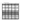
OMX-4001, 4002,4003,4004
VGA / XGA Distribution Amplifiers
INTRODUCTION
Congratulations on your purchase of this OCEAN MATRIX amplifier. This manual
includes configuration, operation and information for the following products from
the OCEAN MATRIX line of distribution amplifiers. These amplifiers are similar
in operation and features.
!
!
!
!
OMX-4001 - 1:3 VGA Distribution Amplifier
OMX-4004 - 1:4 VGA Distribution Amplifier
OMX-4002 - 1:6 VGA/XGA Distribution Amplifier
OMX-4003 - 1:12 VGA/XGA Distribution Amplifier
A Word on VGA/XGA Distribution Amplifiers
VGA/XGA distribution amplifiers distribute one or more signals to several
receivers. They vary in the number of inputs, looping capability, programming
capability, number of outputs, operating format, bandwidth and input/output
coupling. VGA/XGA distribution amplifiers are used to distribute one source to
several acceptors (wide screen projectors, format converters, etc.) for simultaneous
recording or monitoring of one source, with no discernible signal degradation. The
machines excel in very large bandwidth (some approaching 400 MHz) and very
good linearity, making them usable for even the highest graphics standards. A good
quality distribution amplifier amplifies the incoming signal, may pre-compensate
the signal for potential losses (resulting from the use of long cables, noisy source,
etc.) and generates several identical buffered and amplified outputs. The front
panels of these OCEAN MATRIX amplifiers are designed to be simple to operate.
Typical applications of the machines are: computer graphics distribution in classes,
point of sale and multimedia studios, and displaying computer graphics before large
audiences using the data input of a wide screen video projector.
Handling Graphics signals
A computer generated graphics signal is usually comprised of 5 signals: Red,
Green, Blue - which are analog level signals - and two TTL (logic) level signals Horizontal Sync and Vertical Sync. (Digital graphics cards and monitors use a
different signal format, and will not be discussed here, as they are not relevant to
this DA.).
Computer graphics resolution is measured in pixels and signal bandwidth. The
more pixels (picture elements) on the screen, the more detailed is the image. VGA,
S-VGA, XGA, S-XGA and U-XGA are terms describing the graphics resolution
and the color depth. Color depth represents the maximum number of
simultaneously displayed colors on the screen and is measured in bits. 24 and 3236 bits of color depth represent millions to billions of color shades available on the
screen at any given moment. It should be born in mind, though; that the human eye
can resolve only a few thousands colors! The more the image is detailed (higher
resolution) and the higher the color depth, the more real the image will look.
Standard VGA highest resolution was 640x480 pixels with 4 bits of color (16
colors). Standard VGA was able to use more colors (256) but at a lower resolutionaround 320x200 pixels - which was very crude. Common resolutions used today for
computer graphics vary between 1024x768 and 2000x1600 pixels with “high
color” - 16 bits of color (representing 64,000 different colors) up to “true color” 24 bits or more (representing from 16.7 million colors up to several billion.)
Displaying such a detailed and colorful image on the screen needs enormous
graphics memory per frame, as well as very high speeds for “writing” so many
pixels on the screen in real time. Amplifiers that carry such signals must be able to
handle those speeds and signal bandwidths. Standard VGA, at 640x480 resolution,
needed amplifiers with 20-30MHz bandwidth. At 1600x1200 or even at 1280x1024
(S-XGA), such amplifiers will fail completely. In order to faithfully amplify and
transmit modern high-resolution graphics, amplifiers with bandwidths of 300 MHz
and more are needed. Those amplifiers, besides the enormous bandwidth they
handle, need to be linear, to have very low distortion and be stable. Stability of an
amplifier is its ability to avoid bursting into uncontrolled oscillation, which is in
adverse relationship to the speed it can handle. The tendency to oscillate is further
enhanced by the load impedance. The load impedance of a system is usually not
just a resistor. A cable connected to an amplifier (leading to the receiver or
monitor) may present a capacitive and/or inductive load to the amplifier. This is the
main cause of instability. The poor performance of a load or cable may severely
degrade the performance of the amplifier - it’s bandwidth, linearity, and stability and in general its ability to faithfully reproduce the signal.
Cables affect image resolution. Longer cables can cause high frequency
deterioration and hence image “smear” and loss of resolution. In computer graphics
especially, this adverse effect is very much accentuated. Amplifiers should thus
also cope with an additional task - compensating for cable losses up to the
maximum useful operation distance. High-resolution graphics systems must use
very high quality cables for image transmission. The cables should be shielded - to
eliminate externally induced interference though the shield might increase the
capacitance of the cable and, therefore, cause deterioration in the image’s
resolution and clarity. Standard cables can only be a few meters long. For longer
distances, compound cable is separated into five individual coax cables, which are
bulky and cumbersome for use. Even so, the distance is limited to several tens of
meters.
Cables may create other problems if they fail to accurately match the system’s
required impedance. The result of this, especially at high frequencies, is “shadows”
or “ghosts” on the image, resulting from standing waves and electronic reflections
running back and forth between transmitter and receiver. Another aspect to
consider is the sync. As those signals are logic signals, which are not treated as
analog signals, the receiver does not terminate the line, and therefore the line is not
matched. A host of problems might occur when signals are sent over long,
unterminated, unmatched cables. The result might be image breakdown or
distortion due to improper sync information. The amplifier that drives the analog
section of the graphics data should also be able to buffer, recover and send the sync
information in such a way that it will be received properly at the receiver end.
Factors Affecting Quality of Results
There are many factors affecting the quality of results when signals are transmitted
from a source to an acceptor:
!
Connection cables - Low quality cables are susceptible to interference; they
degrade signal quality due to poor matching and cause elevated noise levels. They
should therefore be of the best quality.
!
Sockets and connectors of the sources and acceptors - So often ignored,
they should be of highest quality, since "Zero Ohm" connection resistance is the
objective. Sockets and connectors also must match the required impedance (75ohm
in video). Cheap, low quality connectors tend to rust, thus causing breaks in the
signal path.
!
Amplifying circuitry - Must have quality performance when the desired
end result is high linearity, low distortion and low noise operation.
!
Distance between sources and acceptors - Plays a major role in the final
result. For long distances between sources and acceptors, special measures should
be taken in order to avoid cable losses. These include using higher quality cables or
adding line amplifiers.
!
Interference from neighboring electrical appliances - These can have an
adverse effect on signal quality. Balanced audio lines are less prone to interference,
but unbalanced audio should be installed far from any mains power cables, electric
motors, transmitters, etc. even when the cables are shielded.
How Do I Get Started?
The fastest way to get started is to take your time and do everything right the first
time. Taking 15 minutes to read the manual may save you a few hours later. You
don’t even have to read the whole manual. If a section doesn’t apply to you, you
don’t have to spend your time reading it.
Unpacking and Contents
The items contained in your OCEAN MATRIX distribution amplifier package are
listed below. Please save the original box and packaging materials for possible
future transportation and shipment of the amplifier.
!
!
!
!
!
Amplifier
AC power cable (OMX-4001, OMX-4002, OMX-4003 only)
12 VDC wall transformer (OMX-4004)
User Manual
4 rubber feet
VGA/XGA Distribution Amplifiers
This section describes all the controls and connections of your machine.
Understanding the controls and connections helps you realize the full power of your
machine.
Getting to Know Your OMX-4001 Amplifier
The OCEAN MATRIX OMX-4001 is a full bandwidth, 1:3 VGA/XGA
distribution amplifier designed for computer and workstation applications. The
OMX-4001 splits a VGA/Super-VGA/XGA graphics card output to 3 monitors,
with no discernible signal degradation. Input and output are DC coupled and
conform to the highest standards. Signal bandwidth of 350MHz allows the OMX4001 to be used with the highest quality graphics workstations.
INSTALLATION
Rack Mounting
The OMX-4002 and OMX-4003 amplifiers may be rackmounted in a standard 19”
(1U) EIA rack, and have rack “ears” at the ends of the front panel. To mount them,
simply place the unit's ears against the rack rails of your rack, and insert standard
screws through each of the four corner holes. The OMX-4001 and OMX-4004
models can be table mounted using the rubber feet, or rack mounted using a special
adapter. These devices do not require any specific spacing for ventilation above or
below the unit.
Getting to Know Your OMX-4004 Amplifier
The OCEAN MATRIX OMX-4004 is a full bandwidth, 1:4 VGA/XGA
distribution amplifier designed for computer and workstation applications. The
OMX-4004 splits a VGA/Super-VGA/XGA graphics card output to 4 monitors.
The OMX-4004 is DC fed making it suitable for fieldwork. Both the input and the
output are AC coupled conforming to the highest standards. Signal bandwidth of
350MHz allows the OMX-4004 to be used with the highest quality graphics
workstations.
Connecting TO VGA/XGA Devices
Video sources and output devices (such as monitors, projectors or recorders) may
be connected to the amplifiers through the HD15F type connectors located on the
back of the unit. Unused inputs are terminated to 75ohm, and active inputs should
be terminated by the connecting source. The signals supported by the various
models are Analog Red, Green, Blue signals.
Getting to Know Your OMX-4002 Amplifier
The OCEAN MATRIX OMX-4002 is a full bandwidth, 1:6 VGA/XGA
distribution amplifier designed for computer and workstation applications. The
OMX-4002 splits a VGA/Super-VGA/XGA graphics card output to 6 monitors,
with no discernible signal degradation. Input and output are DC coupled and
conform to the highest standards. Signal bandwidth of 400MHz allows the OMX4002 to be used with the highest quality graphics workstations.
USING THE AMPLIFIERS
Powering on the Amplifier
NOTES
Getting to Know Your OMX-4003 Amplifier
The OCEAN MATRIX OMX-4003 is a full bandwidth, 1:12 VGA/XGA
distribution amplifier designed for computer and workstation applications. The
OMX-4003 splits a VGA/Super-VGA/XGA graphics card output to 12 monitors,
with no discernible signal degradation. Input and output are DC coupled and
conform to the highest standards. Signal bandwidth of 300MHz allows the OMX4003 to be used with the highest quality graphics workstations.
1)
2)
!
!
The amplifier should only be powered on after all connections are completed,
and all source devices have been powered on. Do not attempt to connect or
disconnect any video, audio or control signals to the amplifier while it is
powered on!
The socket-outlet should be near the equipment and should be easily
accessible. To fully disconnect equipment, remove power cord from socket.
Press the toggle switch on the far-left front panel to the up position. The toggle
switch glows.
Operate the acceptors.
Technical Specifications:
OMX-4001
OMX-4004
OMX-4002
OMX-4003
1:3 DA
Analog R, G, B
0.7 Vpp/75
ohms, H, V
syncs TTL
level on HD
15F connector
3 VGA R, G, B
0.7 Vpp/75
ohms, H, V
syncs TTL
level on HD
15F connector
DC
1:4 DA
Analog R, G, B
0.7 Vpp/75
ohms, H, V
syncs TTL level
on HD 15F
connector
4 VGA R, G, B
0.7 Vpp/75
ohms, H, V
syncs TTL level
on HD 15F
connector
AC
1:6 DA
Analog R, G, B
0.7 Vpp/75 ohms,
H, V syncs TTL
level on HD 15F
connector
1:12 DA
Analog R, G, B
0.7 Vpp/75 ohms,
H, V syncs TTL
level on HD 15F
connector
6 VGA R, G, B 0.7 Vpp/75 ohms,
H, V syncs TTL
level on HD 15F
connector
12 VGA R, G, B
0.7 Vpp/75 ohms,
H, V syncs TTL
level on HD 15F
connector
DC
DC
Bandwidth
>350MHz, 3dB
>350MHz, -3dB
400MHz, -3dB
>300MHz, -3dB
Diff. Gain
0.17%
0.5%
0.25%
0.09%
0.06 Deg.
<0.05%
<0.05%
74dB
0.1 Deg.
<0.05%
<0.05%
73dB
0.05 Deg.
<0.05%
<0.1%
75.8dB
0.17 Deg.
< 0.05%
< 0.1%
71dB
24.5x18x4.5
(cm)
9.6" x 7" x 1.8"
24.5x18x4.5
(cm)
9.6" x 7" x 1.8"
48.3x17.8x1U
(cm)
19" x 7" x 1U
48.3x17.8x1U
(cm)
19" x 7" x 1U
1.4kg.
(3.1lbs.)
Approx.
Power Source 115VAC, 50/60
Hz, 4.3VA
1.1kg.
(2.4lbs.)
Approx.
12VDC, 75mA
2.4kg
(5.2lbs.) Approx.
2.7kg.
(6lbs.) Approx.
115VAC, 50/60
Hz 9.2VA
115VAC, 50/60
Hz 15VA
Function
Inputs
Outputs
Coupling
Diff. Phase
K-Factor
Non Linearity
S/N Ratio
Dimensions
(W, D, H)
Weight
OMX-4001, 4002,4003,4004