1
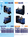
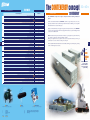
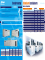
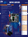
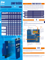
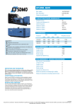
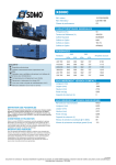
Subsidiaries
ARGENTINA
SDMO ARGENTINA S.A.
TEL./FAX +54 114 836 3511
BELGIUM
SDMO NV/SA
TEL. +32 3 646 04 15 - FAX +32 3 646 06 25
BRAZIL
SDMO DO BRAZIL
TEL. / FAX +55(11) 4390 8434
NIGERIA
SDMO LAGOS
TEL +234 (0)1 776 95 95 - FAX + 33 (0)1 72 27 55 62
SPAIN
SDMO INDUSTRIES IBERICA
TEL. +34 90 230 56 56 - FAX +34 93 580 31 36
UNITED KINGDOM
SDMO ENERGY LTD
TEL. +44(0) 1932 345 777 - FAX +44(0) 1932 350 033
UNITED STATES
TEL. +1 305 863 00 12 - FAX +1 305 863 97 81
Offices
SOUTH AFRICA
ALGERIA
SDMO ALGER
TÉL. +213 21 92 55 84 - FAX +213 21 92 47 76
DUBAÏ
SDMO MIDDLE EAST
TÉL. + 971 50 294 96 94 - FAX +33 1 722 755 75
Photo credit: SDMO - Guillaume Team
SDMO JOHANNESBURG
TÉL. +33(0)6 31 59 47 01 - FAX +33(0)1 72 27 61 51
RUSSIA
PPRPAC/GB-2007/1
SDMO MOSCOW
TÉL. +7 926 838 05 34 - FAX +33(0)1 72 27 55 48
50HZ 60HZ
4933-05.07.L
���������������
����������������������
SDMO Industries - 12 bis rue de la villeneuve
CS 92 848 - 29 228 Brest Cedex 2 - France
Tel. +33 (0)2 98 41 41 41 - Fax +33 (0)2 98 41 63 07
www.sdmo.com
Power products
SDMO GENERATING SETS
1275kVA - 2200kVA
ENGLISH 1091kWe - 2000kWe
A powerful response whatever the
energy required
Whether you require emergency power to be able to cope with possible energy cuts (e.g. hospitals, shopping
centres) or continuous power when conventional electrical grids are faulty (power plants), SDMO will be able to
offer you performance products from a large range which meets all the requirements of different markets.
SDMO is renowned as one of the top manufacturers
o f g e n s e t s worldwide. SDMO has channelled all its energy
into designing a range which is both highly-competitive and highperformance, the largest range available on the market. As a response
to the increasingly precise nature of your energy requirements, which
relate directly to the special traits of your particular industry, SDMO is
devoting the majority of its resources to the continuous improvement
of its range and services.
National coverage,
international presence,
‘‘think globally,
act locally‘‘
In order that SDMO can continue to grow and expand into new
markets, it relies on:
- a distribution network present in over 150 countries,
- 7 overseas subsidiaries,
- 4 representation offices ,
- 7 sales offices and 3 regional divisions in France.
… and 5 storage platforms, which together make for an efficient
commercial network.
The result of a strategy focussed on a single industry: our exacting
professionalism provides you with a reliable source of energy, observing
the strictest of standards. The pioneering mindset of their teams, and
the mastery and flexibility of their production methods mean that SDMO
is constantly innovating. The proximity of their distribution network
and dynamism of their customer services policy enable SDMO to be a
powerful force and provide the basis of the company's values.
SDMO, the source of energy for your comfort and safety.
SDMO, providing the energy that links mankind.
�������������������������������������������������������������������������������������������
PPRPAC/GB-2007/1
50HZ 60HZ
1275kVA - 2200kVA
1091kWe - 2000kWe
The SDMO service
department has been
working to optimise
the performances of
products and to ensure
the safety of all.
Technical assistance to ensure the reliability of our
products
So that you are never without energy, now and in the future,
the After-Sales team will respond to, in the shortest time possible,
any technical question or difficulty encountered with a genset
from the moment it is installed.
Spare Parts Department:
an efficient, well-integrated network
Components are delivered as quickly as possible at the best prices.
Training to produce better levels of response
The means to acquire and update knowledge.
PACIFIC range 60Hz
PACIFIC range 50Hz
50HZ 60HZ
50HZ 60HZ
SDMO
PRODUCT
PLUS
The gensets from the
PACIFIC range are the
winning combination
between robustness and
easy use
T1400
T1800U
5
4
T1540
T2000U
50Hz range
TECHNICAL SPECIFICATIONS
Specifications 50 Hz
400-230 V
RANGE
PACIFIC II
kVA
Cos 0,8
Specifications 60 Hz
480-277 V
GENERATING
SETS (1)
PRP
ESP
Cons 3/4
L/h
T1400
1275
1403
T1540
1400
T1900
1727
(2)
60Hz range
CARACTERISTIQUES TECHNIQUES
Engine specifications
Alternator
Compact version(4)
Engine type
cyl
Bore
(mm)
Stroke
(mm)
Cyl
(L)
Type
Dimensions
Lxlxh (m)
Weight(5)
(kg)
208
S12R-PTA
12
170
180
49,03
501M7
4,33x2,00x2,37
9781
1540
218
S12R-PTA2
12
170
180
49,03
501L8
4,42x2,00x2,37
10147
1900
266
S16R-PTA
16
170
180
65,37
512S55
5,50x2,29x2,48
12891
(3)
RANGE
GENERATING
SETS(1)
kWe
ISO 8528(2)
PRP
ESP
Cons
3/4 L/h
1091
1200
(3)
T1200U
PACIFIC II
Engine specifications
Alternator
Version Compact (5)
Engine type
cyl
Bore
(mm)
Stroke
(mm)
Cyl
(L)
Type
Dimension
Lxlxh (m)
Weight(6)
(kgs)
229
S12R-PTA
12
170
180
49,03
501M7
4,33x2,00x2,37
9781
(4)
T1350U
1228
1350
250
S12R-PTA2
12
170
180
49,03
501L8
4,42x2,00x2,37
10147
T1600U
1455
1600
294
S16R-PTA
16
170
180
65,37
512S55
4,43x2,29x2,48
12891
T2100
1909
2100
304
S16R-PTA2
16
170
180
65,37
512M60
5,60x2,29x2,48
13314
T1800U
1636
1800
346
S16R-PTA2
16
170
180
65,37
512S55
5,50x2,29x2,48
12991
T2200
2000
2200
307,3
S16R-PTAA2
16
170
180
65,37
512M60
5,50x2,29x2,58
14371
T2000U
1818
2000
357
S16R-PTAA2
16
170
18
65,37
512M60
5,50x2,29x2,58
14371
(1)Also available in the following voltages: 415/240 V - 380/220 V
(2)PRP: Prime power available continuously at variable load for an unlimited number of hours per year in accordance with ISO 8528-1, an overload of 10% is available for one hour in 12 hours in accordance with ISO
3046-1
(3)ESP: Standby power available for emergency use at variable load in accordance with ISO 8528-1, no overload available with this service.
(4)The dimensions and weights apply to a generating set specified in the price list, without options
(5)Dry weight - without fuel
(1) Also available in the following voltages : 440/254 V
(2) ISO 8528 : powers specified in compliance with the legislation in force
(3) PRP: Prime power available continuously at variable load for an unlimited number of hours per year in
accordance with ISO 8528-1, an overload of 10% is available for one hour in 12 hours in accordance with
ISO 3046-1
(4)ESP: Standby power available for emergency use at variable load in accordance with ISO 8528-1, no
overload available with this service.
(5)The dimensions and weights apply to a generating set specified in the price list, without options
(6)Dry weight - without fuel
The CONTENERGY concept
EQUIPMENT
BASIC AND OPTIONS
PACIFIC II
Basic and options
cooling
exhaust
starting
diesel
accessories
6
level
generating
set
alternator
engine
4 stroke water-cooled diesel engine
Mechanical adjustement
Standard air filter
Air filter with interchangeable cartridge
220/240V preheating resistance (no control)
IP 23 single bearing alternator, T° class=H, insulation class H/H
Anti condensation resistor
Reinforced insulation
Reinforced insulation and finish
Stator PTC sensor
Bearing PTC sensor
Stator PT 100 sensor
Bearing PT 100 sensor
Synchronizing CT coupling + 3 function regulator
Oversized alternator
CE compliance of the control unit
Mechanically welded chassis with antivibration suspension
Supplied in colour RAL 9005/5007 (black/blue) delivered in shrink-wrap film
Supplied with oil and coolant -30°C
Automatic oil top up with tank
Oil drainage pump
Radiator for wiring T° of 50°C max with mechanical fan(2)
Supplied without coolant
Protective grille for fan and rotating parts
Radiator wiring harness protective grille
Stainless steel compensators
9dB(A) silencer supplied separately
29dB(A) silencer supplied separately
40dB(A) silencer supplied separately
24V charge alternator and starter
Batteries with cables and battery mounting
No battery and battery bracket
Battery isolating switch
Generating set without tank
Separate tank on 500 L container
Separate tank on 1000 L container
Retention container alarm
1m3/h pump auto kit 1
1m3/h pump auto kit 2
4m3/h pump auto kit 2
Diesel separator pre-filter
User manual and commissioning guide (paper version) - French, English or Spanish
User manual and commissioning guide (paper version) - French, English or Spanish (3)
User manual and commissioning guide (CD version) - French, English or Spanish
Engine parts catalogue (paper version) - English
Engine parts catalogue (CD version) - English
Engine repair and workshop manual (paper version) - English
Engine repair and workshop manual (CD version) - English
GENSERVICE replacement parts
1 EN02
Air filter with interchangeable cartridge
•
X
O
EN 21
FD 01
As standard
Not possible
Several possible options
contact us
Option code
Free option
1
2
3
3
•
•
•
EN 02
EN 20
•
AL 01
•
AL 06
AL 07
AL 08
AL 09
AL 10
O(1)
AO 001B
•
•
•
•
EN 18
•
•
FD 11
•
EN 14
•
EN 07
EN 08
EN 09
•
SO 001
•
EN 16
•
FD 06
FD 07
FD 14
FD 08
FD 09
FD 10
FD 05
•
AD 21
AD 22
AD 31
AD 32
AD 41
AD 42
O
3
AD21 et AD 22
User manual and commissioning guide
2
EN08
29 dB silencer
(1)
(2)
(3)
Synchronizing CT coupling not necessary with Mics KERYS
External ambient temperature, reduce by approximately 7°C
Additional copy
INTRODUCTION
50HZ 60HZ
CONTENERGY
The CONTENERGY concept offers a range of soundproof containers featuring a multitude of
options
Thanks to their standard dimensions, CONTENERGY containers are easy to transport and, once on site,
very simple to install: we would recommend that you install them outside the building on a concrete plinth
with suitable trenches for cables and fuel pipes.
Highly economical thanks to its cooling system, integrated sound traps and silencers, the CONTENERGY
concept is completely self-contained, with a fuel capacity which enables it to operate immediately, without
connection to an additional tank.
SDMO understands the many factors that have an influence on your equipment's operation. That is why
our containers are designed to resist exacting climatic conditions.
Whether your equipment needs to operate in extreme cold or tropical environments, let us know your
requirements - we are sure to have the solution you're looking for.
7
Trailers compliant with international standards are also available, allowing you to transform your generating
set into a mobile unit (please contact us)
SDMO
PRODUCT
PLUS
With the CONTENERGY
concept, one simple
connection is all it takes
to get your power plant
up and running.
Conternergy
50HZ 60HZ
CONTENERGY
INTRODUCTION
Standard containers
basic and options
CONTENERGY ISO
SDMO
Basic
PRODUCT
Base member
Starter, 24 V charge alternator
Batteries filled with electrolyte
Standard air filter
Oil drainage pump
Type of soundproofing
High performance integrated 30 dB(A) silencer
Floor
Number of doors
Galvanised air outlet rain grille
Safety lighting and shut-off valve
Exhaust outlet on bracket
RAL 9010 white painted finish for container
Special colour from list
Power cable outlet on lower section
Retention container under container assembly
500 l chassis tank
Tank on container (500 l)
Tank on container (2000 l)
External terminal block
1m3/h pump auto kit 1
1m3/h pump auto kit 2
4m3/h pump auto kit 2
CE compliance of the control unit
MICS Telys control unit
MICS KERYS control unit
Length (mm)
Width (mm)
Height (mm)
PLUS
For environmental
protection purposes our
containers may be fitted
with an optional retention container to hold all
engine fluids.
Container specifications
CIR type containers are more suited to mobile and rental applications. This highly compact model has a
very low sound level and features an optional high volume tank, giving it up to 10 hours of autonomy.
This model is available as a 20 feet “High Cube”
Our containers comply with all current standards and regulations governing these products, including:
Dimensions
Control
units
Fuel
- ISO 668
- NF90-005
- NF ISO 1496-1 (ISO 8323)
•
ISO20 (Silent )
1275kVA - 1540kVA
CIR20 SSI (Super Silent )
1275kVA - 1540kVA
ISO40 (Silent)
1700kVA - 2100kVA
Generating set type
T1400 - T1540
T1200U - T1350U
T1900 - T2100
T1600U - T1800U
Engine
S12R
S12R
S16R
S16R
SILENT
SUPER SILENT
85 - 87 dB(A)@1 m 82-84 dB(A)@1 m
ISO 20 Si
CIR 20 SSi
X
X
ISO 40 Si
X
X
X
SILENT
Basic and options
CONTENERGY CIR
8
EQUIPMENT
BASIC AND OPTIONS
The dimensions of CONTENERGY ISO containers comply with CSC certification. They have been specially
designed to withstand significant loads and pressures during transport without incurring damage, and
for ship transportation without any special constraints.
They are available in two sizes: 20 and 40 feet “High Cube”.
SILENT
79 - 82 dB(A)@7 m
X
ISO 20 Si
X
ISO 40 Si
SUPER SILENT
77-79 dB(A)@7 m
X
CIR 20 SSi
X
X
50HZ 60HZ
As standard
X
Not possible
EN 01
SUPER SILENT
ISO 20 Si
ISO 40 Si
CIR 20 SSi
•
•
SO 001
•
•
Si
•
Bulb plate
2
CT 005
CT 007
CT 011
•
CT 016
CT 015
CT 014
•
X
X
CT 018
CT 008
X
X
•
CM 40
CA 600
6058
2438
2896
•
•
SO 001
•
•
Si
•
Bulb plate
2
CT 005
CT 007
CT 011
•
CT 016
CT 015
CT 014
X
•
X
X
CT 008
CT 009
CT 010
•
CM 40
CA 600
12192
2438
2896
•
•
SO 001
•
•
SSi
•
Bulb plate
3
•
CT 007
CT 011
•
CT 016
CT 015
CT 014
•
X
CT 017
CT 018
CT 008
X
X
•
CM 40
CA 600
6058
2438
2896
Option code
CT 011
Free option
9
electrical control units
50HZ 60HZ
MICS TELYS
SPECIFICATIONS
The new generation of Telys, SDMO's flagship product, integrates all the features of the
previous version, whilst including certain improvements and additions. It is even more
straightforward and user-friendly, with the emphasis on communication (USB connections,
PC connections, control software and remote operation).
Emergency stop
push button
- Built-in fault finding tool guiding the user
in the event of any alarms or faults
- Ability to send(b) e-mail, SMS or fax in the event of any
alarms or faults
- Genset or temporary coupling card as an option (a)
- Optional tropicalisation of the cards to provide protection
in extremely humid conditions (b)
Alarm LEDs
Fault LEDs
Genset start button
Telys "live" LED
Speed/voltage trimming
Power on
Fuel solenoid valve control
Starter control
Preheating plug
Water preheating
Network switch (normal)
Network switch (emergency)
O
●
●
●
O
O
O(1)
O(1)
Oil pressure fault
Coolant temperature fault
Non-starting fault
Overspeed fault
Genset ready to supply
Charging alternator fault
General alarm
General fault
Panel light
STOP, MANU, AUTO, TEST modes
Generating set switch closed (normal)
Network switch closed (emergency)
All alarm and/or fault messages
●
●
●
●
●
●
●
●
●
●
O(1)
O(1)
● LCD
Measurements
● LCD
● LCD
● LCD
ESCAPE button
ON/OFF key
Protection fuse
- Compliance with various legal requirements
or regulations (CE, UL, etc.)
Genset stop
button
- Screen with contrast adapted to all types of lighting
Menu access
button
(a) available from 2007 semester 1
(b) As an option
Oil pressure fault
Coolant temperature fault
Emergency stop fault
Short circuit or overload fault or alarm
Battery voltage min/max fault or alarm
Alternator voltage min/max fault or alarm
Alternator frequency min/max fault or alarm
Overspeed fault
Presence of differential relay fault
Differential relay triggered alarm or fault
●
●
●
●(2)
●(2)
●(2)
●(2)
●
O(3)
O(2=3)
Automatic standby
Automatic shutdown
4 modes
Engine stop for auto cooling
Speed and voltage stabilisation
Preheating plug
Registering retro-information from the normal/emergency switch
Switch from emergency to normal
Switch from normal to emergency
Manual closure of the generating set switch
Manual opening of the generating set switch
Starting on clock
Remote starting order
Three phase mains detection
●
●
●
●
●
O
O(1)
O(1)
O(1)
O(1)
O(1)
O(1)
O(1)
O(4)
Light test
Fault reset
Prewiring for auto-startup
Automatic pack
(charger+relay and engine preheater resistor)
GES pack(5) fitted on the genset(6)
NFPA 110 module (60 Hz)
Adjustable differential protection (time and threshold)
Sound alarm
●
●
O
Scrolling and
selecting wheel
TELYS
IN
Display screen made up of 4 zones:
ZONE 1: Operation mode
(genset running/auto/manual)
FIGURES
ZONE 2: Display of functions via
pictograms
Operation at
-20°C to +60°C
Hygrometry:
95% at 45°, 70% at 50°C,
50% at 60°C
5 language options,
numerous optional
languages
Ability to connect
up to 5 additional input/
output modules
(4 inputs/6 outputs) (b)
ZONE 3: Display of mechanical and
electrical values and the associated
measurements
ZONE 4 : Operating messages and
parameter settings menu
(1) Control and automatic operation present, but require the "Prewiring for auto-startup" option
and possibly the configuration of a parameter on the mics TELYS
(2) The choice of alarm or fault is made by programming on the keyboard
(3) Differential protection is ensured by an exterior module
(4) Mics DS detection is provided using the source changeover switch as a base.
If the source changeover switch is not chosen, the Mics DS module can be fitted in the control unit
(5) To find out more detailed contents, please consult us
(6) Standard NFE37312
O Option
● Standard
● LCD
11
Safety
10
2 USB ports
under a sealed
cover
Engine speed indicator
Battery voltage indicator
Working hours counter
● LCD
O
O
Automatic functions
- Integrated maintenance monitoring programme(a)
(on-screen display of future maintenance operations)
The USB ports facilitate
daily
maintenance or
product updates,
enabling the
configuration
parameters
to be saved
(Telys -> USB key) or,
alternately, the software
to be updated (USB key
-> Telys).
Engine
parameters
PLUS
Its new design, inspired by the NEXYS, has reduced the number of buttons to offer you simplicity when
operating your generating set. It also offers the following
new features:
● LCD
● LCD
● LCD
● LCD
● LCD
● LCD
Controls
PRODUCT
Powers (active, reactive)
Composite voltages
Single voltages
Phase current
Neutral current
Frequency
All states of the generating set,
all starting phases
Analog indicator
Battery ammeter
Indicator lights and/or messages
SDMO
Accessories
PRESENTATION
50HZ 60HZ
Standard with LCD message
For more information on the TELYS, please refer the TELYS documentation (TEL/GB-2007) or speak to your SDMO sales representative
O
O
O
O(2)
O
electrical control units
50HZ 60HZ
Three control units are available in our 650 to 3000 kVA range: the M80, the Mics TELYS (previous pages)
and the Mics KERYS.
Your control unit can be chosen according to your equipment type and perfectly adapted to suit your needs
with the options available. This modularity is made even easier by the fact that each optional peripheral
device (air cooler, daily service tank, oil top-up, etc.) has its own protection.
For power plants, separate control boxes may be used in place of the control units: please do not hesitate
to contact us.
M80
INTRODUCTION
The M80 control unit has a dual functionality. It can be used as a basic terminal block for connecting a control box and as an
instrument panel with a direct read facility, with displays giving a global view of your generating set's basic parameters.
12
PRESENTATION
MICS KERYS
50HZ 60HZ
The Mics KERYS is a user-friendly, easy to grasp tool, offering a wide range of functions. It is fitted as standard to all generating
sets designed for coupling applications, and can be fitted as an option, from 200 kVA, to the rest of our applications. So that all
the requirements of high and low voltage power plants can be met, the Mics KERYS can be built into the console, fitted directly
onto the generating set or on a separate cabinet. It complies with CE, UL and CSA standards.
Control keypad
with display LEDs
Display screen
7.4 inch LCD TFT
Selecting manual mode
Colour graphic display
Selecting stop mode
Touch screen
Selecting automatic mode
Dimensions:
Opening/closing the genset
154 mm x 86 mm
circuit breaker
Activating/deactivating the test
Parameter setting keypad
Opening/closing the grid
For setting parameters,
circuit breaker
navigating and directly
LED test
accessing the screens
Stop horn
Fault clearance
13
Coolant temperature
Tachometer
Directional keypad
with LED showing activity
Oil pressure
The Mics KERYS is available in two versions. The basic MMI (Man/Machine Interface) includes a monochrome LCD screen with a
functions keypad. The top of the range version of the Mics KERYS Tactil has a TFT colour touch screen. Both of these two versions has an
ergonomic interface for configuration, operation or fault finding.
Emergency
stop button
ADDITIONAL SPECIFICATIONS
Measurements
Power factor in the different screens
Active and reactive powers
Synchronism (difference in phase, voltage and
frequency)
Harmonics in voltage and current
SPECIFICATIONS
Measurements
Engine parameters
Controls
Miscellaneous
•
BASIC TERMINAL
BLOCK
M 80
Tachometer (54 mm)
X
•
Oil pressure
gauge
X
•
Coolant temperature
indicator
X
•
Oil temperature
indicator
X
O
Emergency stop
•
•
CE compliant
•
•
Customer connection terminal
block
•
•
As standard
X
Not possible
O
Safety features
Overload, short circuit
Phase current direction
Neutral current
Reverse component
Voltage reserve
Thermal image
Presence and absence of voltage
Maximum active power
Active and reactive power return
Homo-polar current and homo-polar current
direction
Restricted earth and homo-polar voltage
Vector jump, min Z and df/dt
Synchronisation
Manual and automatic
Frequency and voltage equalisation
Options
Adjustment
Speed and voltage
Switching frequency and voltage set values
Adjusting frequency and voltage set values
Adjusting active and reactive power set values
Active and reactive power surge keyway
Active and reactive power distribution
Active and reactive power return setting
Manual control of speed and voltage regulations
Communication
In local mode or remote mode
Built-in Web server
Via RS485 connection
Via Ethernet (in local mode) and Internet (in
remote mode)
Plus points integrated as standard
Fault finding aid
Assistance and maintenance (history, sending
of emails...)
Mechanical and electrical parameter archives
and curves
Load impact management
Addition of supplementary software without
external tool
* For more information, please refer to the Mics KERYS documentation
or speak to your SDMO sales representative.
Configurations
A612: Genset without grid
A622: Genset with normal/emergency switch
and grid without coupling
A633: Production plant without grid
A634: Production plant with grid and normal/
emergency switch (no grid coupling)
A641: Genset with permanent coupling
to grid without normal/emergency switch Grid coupling + resale
A642: Genset with permanent coupling to grid
without normal/emergency switch Grid coupling + power level 0 kW on the grid
A651: Genset with temporary coupling to grid
and normal/emergency switch
A661: Genset with permanent coupling to grid
and normal/emergency switch
REMOTE OPERATION AND CONTROL
Display
screen
for electrical
data
The Mics KERYS and KERYS Tactil are supplied as standard
with integrated operational software. The
60 resident screens enable you to have complete
control over your installation, regardless of the
distance (operation and parameter setting).
power modules
50HZ 60HZ
AIPR
SPECIFICATIONS
Each generating set may be supplied with a protection unit.
This unit is mounted on the chassis with connection cables to the alternator. It is located on the right-hand side of the generating
set.
Rating
AUTOMATIC TRANSFER SWITCH
PRESENTATION
SDMO provides a complete range of separate Automatic Transfer Switch. There are a large number of benefits to our technology,
both in terms of cost and of ease of installation. The design of the control units and boxes enables even cables with large cross
sections to be easily connected. The front panel of the unit no longer opens on just one side, like a conventional control unit,
but on three sides, allowing total access to all the connections for the power equipment and terminal blocks. All our control units
are either three-pole or four-pole. The TSI module (Transfer Switch Intelligence) is fitted as standard to our entire range of normal/
emergency switches, whatever the rating of their switching component (from 25A to 3200A).
25A
32A
45A
63A
110A
140A
200A
250A
400A
630A
208-440V
•
•
•
•
•
•
•
•
•
•
•
•
•
By switches
•
•
•
•
•
•
•
x
x
x
x
x
x
800A
1250A
1600A
2000A
2500A
3200A
4000A
Voltage
Fixed 3 pole compact circuit breaker
•
•
•
X
X
X
X
Changeover
Fixed 3 pole open circuit breaker
X
X
X
•
•
•
•
Fixed 4 pole compact circuit breaker
O
O
O
X
X
X
X
Fixed 4 pole open circuit breaker
X
X
X
O
O
O
O
(1) Integrated into a floor-mounted control box
With 3 or 4 pole open circuit breaker only
O
O
O
O
O
O
O
PRESENTATION
208-440 V
•
•
•
•
•
•
•
Auxiliary unit option (2)
O
O
O
O
O
O
O
Power connection bus bars
•
•
•
•
•
•
•
With manual control on the front
Dimensions
•
•
•
•
•
•
•
Protection index
IP 207
IP 207
IP 207
IP 207
IP 207
IP 207
IP 207
height (mm)
1260
1260
1260
1260
1260
1260
1260
width (mm)
683
683
683
683
683
683
683
depth (mm)
365
365
365
365
365
365
365
height (mm)
1664
1664
1664
1664
1664
1664
1664
Remote control terminal block
DIMENSIONS
(without air cooler unit)
DIMENSIONS
(with air cooler unit)
1
DIMENSIONS
(with connection unit
on upper section)
2
width (mm)
683
683
683
683
683
683
683
depth (mm)
365
365
365
365
365
365
365
height (mm)
1883
1883
1883
1883
1883
1883
1883
width (mm)
683
683
683
683
683
683
683
depth (mm)
365
365
365
365
365
365
365
(1) The motorised control includes a closure solenoid valve, a shunt trip coil and an
AC motor
(2) The auxiliary unit option is mounted above the main unit. It is used for the power
connections of generating set auxiliaries, eg.:
- air cooler output
- fuel pump unit output
• Standard
O Option
X Not possible
2500A(1)
3150A(1)
•
•
•
x
x
x
By changeover contactors
x
x
x
x
x
x
x
•
•
•
•
•
•
•
•
•
Heights (mm)
500
500
500
500
500
500
600
800
800
800
1000
1000
1000
1800(2)
1800(2)
1800(2)
Width (mm)
430
430
430
430
430
430
600
600
600
600
800
800
800
1000
1000
1000
Depth (mm)
200
200
200
200
200
200
250
400
400
400
500
500
500
800
800
800
(2) On a base plate h=200 mm, i.e. control box of height 1600 + 200
Motorised control option (1)
14
800A 1000A 1600A 2000A(1)
TSI
Both innovative and original in design, the TSI is perfectly suited to applications where the transfer of a main source to a replacement source is crucial for the
running of your installations.
Straightforward and easy to use, the special feature of this module is that it is automatically configured when voltage is provided from the grid side.
By simply pressing the AUTO key, the following parameters are configured: grid voltage, voltage min/max thresholds, type of use, frequency min/max
thresholds.
Electronic switching of the power source means that the unit can be continuously self-supplied.
Screen
with integrated backlighting, with
2 lines of 16 characters
Confirm key
Rotophase LED
Shows the direction
of rotation
of the phases
Source Status LED
Three-colour LED
showing the status
of the source
Position LED
LED showing the
closed position
of the switch or
changeover switch
15
Navigation
and selection
keys
used for scrolling through
the different electrical value
display screens and for
configuring all the module
parameters to the customer
specifications
Test
used to simulate
generating set starting,
including the possibility of
a changeover sequence
Operating keys
Auto key: automatic configuration
of the module, for automatic operation
in mains power cut or a drop
in voltage
SPECIFICATIONS
Key 1: Forced source 1 operation
Key 2: Forced source 2 operation
Reset key: clears the fault display
TSI MODULE
2 lines on the screen, enabling simultaneous display of the voltage on the grid side and the generating set side. The same applies to the frequency.
6 LEDs provide instantaneous information on the position status of both of the two 2 sources, along with any alarms and faults which arise.
The TSI also offers 3 configurable inputs and 2 outputs, as an option.
ADDITIONAL SPECIFICATIONS
Communication
In addition to a wired connection which enables remote starting via dry contact with all the SDMO control/command modules (Nexys, Telys, Kerys), the
TSI module also has a CAN Bus (as an option from 25A to 200A), allowing it to communicate with the MICS Kerys.
This connection allows all information relating to the grid and the starting order following a variation in voltage to be sent to the Kerys.
1
unit with standard connection
2
unit with connection from above
(with integrated air cooler unit on the lower section if necessary)