1
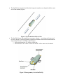
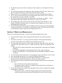
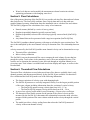
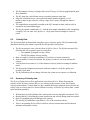
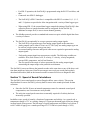
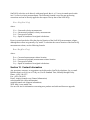
SonTek IQ - Principles of Operation
SonTek IQ - Principles of Operation
This doument introduces the operating principles of the SonTek IQ acoustic Doppler current
meter. It does not attempt to provide a detailed discussion of all technical issues, nor does it
provide a detailed description of SonTek IQ operation. To learn more about specific SonTek IQ
applications, please refer to other sections of the SonTek IQ User’s Manual or contact SonTek
Support.
Section 1. Overview
The SonTek IQ (or IQ) is a Doppler current meter designed for water velocity, level, and flow
measurements in the field. The SonTek IQ provides the technological advantages of
complex/expensive current profilers, but in a simple, inexpensive, and easy to use package.
SonTek IQ attributes include:
•
•
•
•
•
•
•
•
Horizontally and vertically integrated velocity measurement (using along axis and skew
beams)
Measurements to the maximum possible extent of the water column
Invariant factory calibration — no periodic recalibration required
Simple operation (very few user entries needed)
Excellent performance for low and high flows
Accuracy — 1% of measured velocity
Water level measured by vertical beam and pressure sensor
Built-in temperature sensor
The SonTek IQ combines horizontally and vertically integrated velocity data with precise stage
measurements to give real-time flow data. A variety of real-time flow calculations is supported
and are presented below.
•
•
•
•
•
•
Natural streams
Regular (trapezoidal) channels (typically concrete lined)
Irregular channels (typically, not lined or earthen channels)
Theoretical flow calculations
Full support for index velocity sites (SonTek IQ Plus)
Calculation of total water volume for water deliveries
Section 2. The Doppler Shift
The SonTek IQ measures the velocity of water using a physical principle called the Doppler
shift. This principle states that if a source of sound is moving relative to the receiver, the
frequency of the sound at the receiver is shifted from the transmit frequency. For a Doppler
current meter, this can be expressed as:
Fd= = (− 2 F0)(V/C)
Where:
Fd = Change in received frequency (Doppler shift)
F0 = Frequency of transmitted sound
V = Represents the relative velocity between source and receiver (i.e., motion that changes
the distance between the two); positive V indicates that the distance from source to receiver
is increasing
C = Speed of sound
The SonTek IQ is a monostatic Doppler current meter. (Figure) illustrates the operation of a
monostatic Doppler current meter.
•
•
•
•
•
•
•
•
Monostatic means the same transducer is used as transmitter and receiver.
The transducer generates a short pulse of sound at a known frequency (F0), which then
propagates through the water.
The transducer is constructed to generate a narrow beam of sound where the majority of
energy is concentrated in a cone a few degrees wide.
As the sound travels through the water, it is reflected in all directions by particulate
matter (i.e., sediment, biological matter, bubbles).
Some of the reflected energy travels back along the transducer axis, where the transducer
receives it.
The SonTek IQ electronics measure the change in frequency of the received signal.
The Doppler shift measured by a single transducer relates to the velocity of the water
along the axis of the acoustic beam of that transducer.
If the distance between the transducer and the target is decreasing, frequency (FD)
increases; if the distance is increasing, frequency (FD) decreases. Motion perpendicular to
the line-connecting source and receiver has no effect on the frequency of received sound.
>
<
Figure 1. Measuring water velocity using a target with a monostatic Doppler system
The location of measurements made by a monostatic Doppler current meter is a function of the
time at which the return signal is sampled.
•
•
The time since the pulse was transmitted determines how far the pulse has propagated,
and thus specifies the location of the particles that are the source of the reflected signal.
By measuring the return signal at different times following the transmit pulse (TP), the
SonTek IQ measures the water velocity at different distances from the transducer.
It is important to note that the SonTek IQ measures the velocities of particles in the water, and
not the velocity of the water itself.
•
•
The velocity of particles in the water is assumed to match the velocity of the water. This
assumption has been tested extensively and found to be highly reliable.
If there is no particulate matter in the water, the SonTek IQ is unable to measure velocity.
In general, the practical limitation of clear water is not whether the SonTek IQ can make
velocity measurements, but what is the maximum range (distance from the system) at
which the SonTek IQ can measure velocity. In clear water, the maximum measurement
range may be reduced.
Important Note: Clear water is a relative term; visual inspection is not a good way to
determine particulate matter concentration. Beam Check, in the Utilities Tab of the SonTek
IQ software can be used to make an on-site field determination of range.
Section 3. Beam Geometry
The SonTek IQ as a flowmeter and is mounted in the bottom of channels. In this type of
installation, the SonTek IQ measures velocity along the axis of flow as well as horizontally using
the along-axis beams skew beams respectively.
•
•
The SonTek IQ is mounted such that the along axis transducer are aligned with the center
axis of the channel (Figure).
Figure 2. IQ orientation relative to flow
The SonTek IQ uses four transducers to measure velocity — two along-axis beams and
two skew beams. This beam geometry optimizes the balance between total measurement
range and performance in shallow water (Figure).
o Along axis beams are 25° off the vertical axis
o Skew beams are 60° off the vertical axis and 60° of the center axis of channel
Figure 3. Beam geometry for the SonTek IQ
•
•
•
•
•
•
•
The SonTek IQ uses the relative orientation of the transducers to calculate the 3D water
velocity
The velocity measured by one transducer is the projection of the 2D water velocity onto
the axis of the acoustic beam, and is referred to as the beam velocity.
Beam velocities are converted to XY (Cartesian) velocities using the beam geometry.
The X velocity for the SonTek IQ is the along-channel water velocity; the Y velocity is
the vertical water velocity (typically very small).
The SonTek IQ typically measures as much of the water column as possible — from a
short distance above the transducer head all the way to the water surface.
The starting point of the velocity measurement is 0.08 m above the transducer. This
distance (called the blanking distance) is required for the transducers to recover after
transmitting the acoustic pulse.
The SonTek IQ dynamically adjusts the ending point of the velocity measurement based
on the measured water level from the vertical acoustic beam. This allows the SonTek IQ
to automatically optimize operation with changing water level.
Section 4. Water Level Measurement
Water level is determined by using a vertical beam and integrated pressure sensor.
•
•
•
•
•
•
•
•
The vertical beam sends a short sound pulse and listens for the reflection from the
surface.
The surface reflection is very strong and clearly defined, allowing the SonTek IQ to
precisely measure the time at which the return reflection is received.
To convert the reflection time to surface range, the SonTek IQ needs to know the speed
of sound in the water at the survey site, which is primarily a function of temperature and
salinity.
o The SonTek IQ’s internal temperature sensor automatically compensates for changing
conditions
o by continually updating the sound speed used for surface range calculations.
o Salinity is user defined (i.e., the SonTek IQ does not automatically adjust for salinity
variations).
The vertical beam also works under ice, measuring the range to the bottom of the ice (this
gives water depth beneath the ice as needed for discharge monitoring).
The vertical beam can operate with water depths from 0.08 to 1.5 m (above the
transducer) for the SonTek IQ and 0.08 to 5 m for the SonTek IQ plus.
The vertical beam works in conjunction with the integrated pressure sensor to determine
water level
o The vertical beam is the principle measurement
o The pressure sensor is used as a secondary measurement in the case that there is
not data from the vertical beam
The pressure sensor is not vented to the atmosphere thus it must be calibrated for changes
in atmospheric conditions.
o The pressure sensor is calibrated during the deployment using data from the
vertical beam thus both sensor provide reliable and accurate water level data.
•
Water level data are used to modify the measurement volume location in real-time,
optimizing performance with changing water level.
Section 5. Flow Calculations
One of the primary functions of the SonTek IQ is to provide real-time flow data and total volume
data for deliveries. The SonTek IQ combines water velocity data and level data with usersupplied channel geometry information about the installation site to calculate flow and volume.
The SonTek IQ supports flow calculations for a variety of environments.
•
•
•
•
Natural streams (defined by a series of survey points)
Regular (trapezoidal) channels (typically concrete lined)
Regular (trapezoidal) culverts with a closed top (typically concrete lined) (SonTek IQ
Plus)
Any channel that can be represented with a stage/area equation (SonTek IQ Plus)
The SonTek IQ combines channel geometry with stage to calculate the cross-sectional area. The
area is then multiplied by the mean channel velocity to determine flow. The relationship between
the
velocity measured by the SonTek IQ and the mean channel velocity can be determined two ways.
•
•
Theoretical flow calculations
Index velocity calibration
The SonTek IQ can use the measured flow rate to compute the total volume of water that has
passed the system. Total volume is the cumulative sum of flow rate multiplied by time. This
could be use to determine the amount of water delivered through an irrigation channel over a
given time span. Total volume is available both in real-time display and output, as well as in the
recorded data.
Section 6. Theoretical Flow Calculations
Theoretical flow calculations are used when no reference flow data are available; that is, only
channel geometry and data measured directly by the SonTek IQ are available. For theoretical
flow calculations the SonTek IQ makes use of the following information.
•
•
•
•
•
The largest variations of velocity occur with changing depth
The SonTek IQ measures a vertically integrated velocity over the largest possible portion
of the water column, including information about the variation of vertical velocity
o The SonTek IQ outputs average velocity data from 0.08 – 1.5 m
o The SonTek IQ Plus outputs velocity profile data from 0.08 – 5.0 m
A power-law velocity profile model is used, assuming a 1/6 power-law coefficient.
The theoretical flow model accounts for the portion of the vertical velocity profile
measured by the SonTek IQ. It determines the relationship between the mean velocities
measured in this portion of the water column with the mean velocity through the vertical
profile.
The model provides a velocity scaling factor that relates the SonTek IQ measured
velocity to the mean channel velocity.
•
The flow model is customized based on specified channel type — open channel, round
pipe (full/partially full), elliptical pipe (full/partially full), or closed culvert (full/partially
full).
Section 7. Index Velocity Calibration
An index velocity calibration is a popular technique for monitoring discharge when reference
discharge measurements are available.
•
•
•
•
Discharge measurements are made at a variety of water levels and flow conditions.
SonTek IQ water velocity data and stage data are collected at the same time as reference
discharge measurements.
The data are analyzed to determine empirically a relationship between the SonTek IQ
measured velocity and the mean channel velocity. This empirical relationship is then
input into the IQ, which outputs calibrated flow data in real time.
The empirical index relationship uses the following form:
Vmean = Vintercept + Vmeas * (Vslope + (StageCoef * Stage))
where:
Vmean = mean velocity in the channel
Vintercept = user-supplied* velocity offset (cm/s or ft/s)
Vmeas = IQ measured velocity
Vslope = user-supplied* velocity scale factor (no units)
StageCoef = user-supplied* water depth coefficient (1/s)
Stage = measured stage (total water depth) (m or ft)
*Important note: These constants are empirically derived coefficients based on a number of
user-made, independent discharge measurements. These coefficients relate SonTek IQ measured
velocity to mean channel velocity as determined by the independent measurements. The details
of how these constants are derived are beyond the scope of this appendix. For information,
contact SonTek.
An index velocity calibration will usually supply more accurate flow data than a theoretical flow
calculation. However, an index calibration requires extensive reference data and data analysis
expertise to construct — for many applications, this is not practical. In these situations, the
theoretical flow calculations can provide good quality flow data.
Section 8. SonTek IQ Data
Below are details on collecting data with th SonTek IQ.
8.1.
Sampling Strategy
The SonTek IQ averages data for a fixed interval for each reported water velocity sample.
•
•
•
•
•
8.2.
The IQ samples velocity (via ping) each second. The type of velocity pings depends upon
flow conditions.
The IQ pings the vertical beam once per second to measure stage data.
Pings are accumulated over a user-specified sample duration (typically 1 to 15
minutes) and average values for velocity, stage, and a variety of diagnostic data are
reported.
The sampled data are normally recorded to the IQ’s internal recorder, and can also be
reported to an external data logger.
The IQ can operate continuously (i.e., start the next sample immediately after completing
a sample), or it can enter a low power (i.e., sleep) state between samples to conserve
power.
Velocity Data
The IQ velocity data are determined using three types of acoustic pulses. The IQ automatically
determines the best pulse scheme to provide the best possible velocity data.
•
•
•
•
•
•
8.3.
The IQ can measure water velocities from ±0.001 to 10 m/s. The IQ also measures flow
direction and will accurately report reversing flow.
o The standard IQ outputs average velocity
o The IQ Plus outputs velocity profiles
Data are output in Cartesian coordinates (XY) relative to system orientation.
If one transducer is buried or blocked, the IQ may switch to a one-beam solution for
velocity.
Velocity data are accurate to 1% of the measured velocity (after accounting for random
noise).
The IQ provides diagnostic parameters with each sample to verify the quality and
accuracy of the data.
The IQ calibration will not change with time; the system never requires re-calibration.
Accuracy of Velocity data
The IQ is well suited to low-flow applications to less than 0.01 m/s. When discussing the
accuracy of the IQ water velocity data, we are referring to the presence of any bias in mean
velocity measurements. Velocity data may have random short-term variations (noise) that do not
reflect a bias to velocity data Two factors influence accuracy of SonTek IQ velocity data: sound
speed and beam geometry.
•
•
•
•
•
With properly specified salinity data, sound speed errors are negligible (less than 0.25%).
Beam geometry is fixed during system construction and will not change with time (unless
there is catastrophic physical damage to the system).
The SonTek IQ calibration is specified to 1.0% of the measured velocity.
There is no potential for zero offset or drift in velocity measurements and no inherent
minimum measurable velocity.
8.4.
Signal-to- Noise Ratio
The SonTek IQ measures velocity by looking at the reflections of an acoustic pulse from
particles in the water.
•
•
•
•
•
•
•
The magnitude of the reflection is called signal strength. It varies with the amount and
type of suspended material, and with the distance from the transducers.
Signal strength decreases with distance from the transducer due to geometric spreading
and sound absorption.
The distance at which signal strength approaches the electronics noise level determines
the maximum measurement range of the SonTek IQ.
Signal strength is commonly used as the signal-to-noise ratio (SNR), which compares the
magnitude of the received signal to the ambient electronics noise level. SNR is reported
in logarithmic scale.
Signal strength data are measured and recorded in internal logarithmic units called
counts.
o Signal strength and noise level are recorded in counts; one count equals 0.43 dB.
o Signal strength is converted to SNR by subtracting the noise level and converting to
dB.
The SonTek IQ requires a minimum SNR (≈3 dB) to make accurate velocity
measurements.
For the SonTek IQ, the location and size of the measurement volume is variable over a range
up to 1.5 m for the standard SonTek IQ and up to 5.0 m from the SonTek IQ Plus.
•
Signal strength and SNR reported are the mean value over the measurement volume.
•
Signal strength decreases with range from the transducers and will vary with conditions
in the water. For good operating conditions, SNR should be greater than 3 dB.
The SonTek IQ will continuously change vertical extent of the measurement based on water
depth.
•
In most conditions, the SonTek IQ is able to measure to the specified maximum range of
5 m for the SonTek IQ Plus and 1.5 m for the standard SonTek IQ.
•
If at any point the signal strength is too low for reliable velocity measurements, the
SonTek IQ will end the measurement volume at that range. In this situation, the system
will automatically cut off the measurement volume at the maximum effective range. The
exact limits of the measurement volume are recorded with each sample.
Signal strength is primarily a function of the amount and type of particulate matter in the water.
While signal strength cannot be immediately converted to sediment concentration, it provides an
excellent qualitative picture of sediment fluctuations and, with proper calibration, can be used to
estimate sediment concentration.
Section 9. Flow Data
With each sample, the SonTek IQ records cross-sectional area and flow.
•
•
Cross-sectional area depends on the user-supplied channel geometry and water level
determined by the vertical beam and pressure sensor.
Typically, the accuracy of area data is most strongly influenced by the accuracy of
channel geometry, rather than uncertainty in stage data.
The IQ can also be programmed to calculate total volume in addition for flow rate.
•
•
•
Total volume is the cumulative sum of flow rate multiplied by elapsed time, and
represents the total volume of water than has passed the SonTek IQ.
Total volume can be accumulated continuously between files (when data collection is
interrupted and restarted) or reset with each data file. Several methods are also provided
to reset total volume (restart the accumulation at zero) within a data file, if required.
Total volume can be output in a variety of different units as required by the user.
The accuracy of flow data depends on a few factors.
• Accuracy of cross-sectional area
• Accuracy of velocity data
• Method used to relate measured velocity to mean channel velocity
In general, the largest factor in determining the accuracy of flow data is the method used to relate
measured velocity to mean velocity. Some guidelines are presented below:
• A well-established index calibration can give real-time flow accuracy of about 2-3% of
the measured flow.
• Theoretical flow calculations in a regular channel (i.e., trapezoidal, concrete lined) may
give accuracy of about 3-5%. This can be strongly affected by nearby intake or outlet
structures or by nearby changes in channel geometry (including bends in the channel).
Theoretical flow calculations in natural streams are difficult. They can provide reasonable results
in streams with a simple, uniform cross section, but are notably limited in wide, shallow streams
where velocity can vary dramatically across the width of the stream.
Section 10. Real-time Data Output
The SonTek IQ offers several options for real-time data output, including SDI-12, Modbus,
RS232 ASCII and 4-20 mA outputs.
•
•
Only one real-time output type (RS232, RS422, SDI-12, Modbus, analog outputs) can be
used at a time.
The SDI-12 serial bus can be used to output a portion of the SonTek IQ sample data,
including velocity and limited diagnostic data. Multi-cell velocity data can also be output
in real-time using SDI-12.
o For SDI-12 operation, the SonTek IQ is programmed using the RS-232 serial bus, and
then
o Connected into SDI-12 datalogger.
o The SonTek IQ’s SDI-12 interface is compatible with SDI-12 revisions 1.0, 1.1, 1.2,
and 1.3. Options are provided to allow integration with a variety of data logger types.
o When using SDI-12, the external data logger controls the timing of SonTek IQ’s data
collection; however sample duration must be configured for the SonTek IQ,
additional to output flow, be sure to insert channel geometry.
•
The Modbus protocol provides a standardized means to acquire reliable digital data from
a variety of sensors.
•
The SonTek IQ can optionally be set up to generate analog output signals.
o The SonTek IQ can generate up to four analog output signals at the same time.
o Analog outputs can be either 4-20 mA or 0-5 VDC (only one analog output type can
be used on a single system at any given time).
o An external analog converter and special software are required to generate the analog
output signals.
Each analog output signal can represent one variable. The following variables are
available: flow, total volume, level, X-velocity, Y-velocity, velocity magnitude,
average SNR, temperature, and cell end location.
o The user specifies the range of values represented by the analog output signal,
customizing the output range to the particular environment.
o
The SonTek IQ can record data to the internal recorder at the same time as any of the above realtime data outputs are being used. SonTek encourages users to always record (and regularly
download and archive) data on the internal recorder to ensure full access to diagnostic data.
Section 11. Speed of Sound Calculations
The SonTek IQ uses sound speed to convert Doppler shift to water velocity. This section
describeshow to correct SonTek IQ velocity data for errors in the sound speed used for data
collection.
•
•
Since the SonTek IQ uses an internal temperature sensor for automatic sound speed
compensation, user corrections are rarely needed.
The only time sound speed corrections are normally required is if salinity has been
incorrectly specified.
In shallow water, speed of sound is a function of temperature and salinity. As a general rule, a
temperature change of 5°C or a salinity change of 12 parts per thousand (ppt) results in a change
in sound speed of one percent. The full range of typical temperature and salinity levels (from -5
to 60°C and 0-60 ppt) gives a sound speed range of 1375-1600 m/s (total change of 14%).
SonTek IQ velocities scale directly with sound speed; that is, a 1% error in sound speed results
in a 1% error in velocity measurements. The following formula is used for post-processing
corrections and can be directly applied to the output velocity data of the SonTek IQ.
Vtrue = Vorig (Ctrue / Corig)
where:
Vtrue = Corrected velocity measurements
Vorig = Uncorrected (original) velocity measurements
Ctrue = True speed of sound
Corig = Speed of sound used in original calculations
Errors in sound speed also affect the physical location of the SonTek IQ measurement volume,
although these errors are generally very small. To calculate the correct location of the SonTek IQ
measurement volume, use the following formula.
Ztrue = Zorig (Ctrue / Corig)
where:
Ztrue = Corrected measurement volume location
Zorig = Uncorrected (original) measurement volume location
Ctrue = True speed of sound
Corig = Speed of sound used in original calculations
Section 12. Contact Information
Any questions, concerns, or suggestions can be directed to SonTek by telephone, fax, or email.
Business hours are 8:00 a.m. to 5:00 p.m., Pacific Standard Time, Monday through Friday.
Phone : (858) 546-8327
Fax : (858) 546-8150
Email : [email protected] (General information)
[email protected] (Sales information)
[email protected] (Support information)
Web : http://www.sontek.com
See our web site for information concerning new products and software/firmware upgrades.
SonTek/YSI, founded in 1992 and advancing environmental science in over 100 countries,
manufactures affordable, reliable acoustic Doppler instruments for water velocity measurement
in oceans, rivers, lakes, harbors, estuaries, and laboratories. SonTek, and SonTek-IQ are
trademarks of YSI Inc., Yellow Springs, OH, USA. The SonTek-IQ is made in the USA.