1
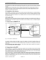
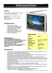
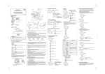
SICLOCK® DCF S7-Interface 2XV9450-1AR35 Betriebsanleitung • User Manual D Deutsch Version 1.0 Stand: Oktober 2005 GB English Gesamtpaket 2XV9450-1AR36 Bestell.Nr.: 2XV9450-1AR31 Betriebsanleitung SICLOCK DCFS7 Verantwortlicher Vertrieb: Siemens AG, I&S EDM, Erlangen Ansprechpartner: örtliche Siemens-Niederlassung Bestellungen: örtliche Siemens-Niederlassung Herausgegeben von: Siemens AG I&S EDM Frauenauracher Straße 98 D-91056 Erlangen SICLOCK-Hotline: Tel.: ++49 (9131) 7-2 88 66 Fax: ++49 (9131) 18-8 06 04 Technische Änderungen vorbehalten E-mail: [email protected] WWW: http://www.siemens.de/siclock Siemens AG 2000, 2001, 2004, 2005 2 Version 1.0 Bestellnummer 2XV9450-1AR31 Betriebsanleitung SICLOCK DCFS7 Inhaltsverzeichnis 1 Lieferumfang........................................................................................................................................ 4 2 Inbetriebnahme.................................................................................................................................... 4 2.1 Funktionsbeschreibung................................................................................................................. 4 2.2 Installation des Interfaces ............................................................................................................. 4 2.3 Installation der Antenne ................................................................................................................ 5 2.4 Funktionstest................................................................................................................................. 5 3. Anschluss an SIMATIC S7 .................................................................................................................. 5 4. Anschluss an Steuerung...................................................................................................................... 5 5 Technische Daten................................................................................................................................ 6 5.1 Schnittstelle................................................................................................................................... 6 5.2 Betriebsdaten ................................................................................................................................ 6 6 Bestelldaten ......................................................................................................................................... 6 Abbildungsverzeichnis Abbildung 1: Anschluss-Schema an eine SIMATIC S7........................................................................... 5 Tabellenverzeichnis Tabelle 1: Belegung der SUBD-Schnittstelle........................................................................................... 6 Bestellnummer 2XV9450-1AR31 Version 1.0 3 Betriebsanleitung SICLOCK DCFS7 1 Lieferumfang Im Lieferumfang des SICLOCK DCF-S7 - Interfaces (Bestellnummer 2XV9450-1AR35).sind folgende Komponenten enthalten: • 9 poliger DSUB-Stecker mit eingebautem Interface und 5m Kabel. • Betriebsanleitung für das SICLOCK DCF-S7 - Interface (Bestellnummer 2XV9450-1AR31). Im Lieferumfang des Gesamtpakets SICLOCK DCF-S7 (Bestellnummer 2XV9450-1AR36) sind folgende Komponenten enthalten: • 9 poliger DSUB-Stecker mit eingebautem Interface und 5m Kabel (Bestellnummer 2XV9450-1AR35). • Aktive Antenne SICLOCK DCFRS (Bestellnummer 2XV9450-1AR06) • Betriebsanleitung für das SICLOCK DCF-S7 - Interface (Bestellnummer 2XV9450-1AR31). • 3½“-Diskette mit den Funktions- und Datenbausteinen (Bestell Nr. 2XV9450-1AR32). • Installationsanleitung für SICLOCK DCF77-Empfangsdienst für SIMATIC S7 (Bestellnummer 2XV9450-1AR33). Zum Aufbau einer DCF77-Synchronisation außerhalb der Reichweite des DCF77-Senders in Mainflingen bei Frankfurt wird das Gesamtpaket SICLOCK GPSDEC (Bestellnummer 2XV9450-1AR00) in Verbindung mit 2XV9450-1AR32 benötigt. 2 Inbetriebnahme Die Inbetriebnahme des SICLOCK DCF-S7 - Interface erfolgt in folgenden Schritten: • Anschluss des SICLOCK DCF-S7 - Interfaces an die S7 oder eine sonstige geeignete Eingabebaugruppe. • Montage der Antenne SICLOCK DCFRS (2XV9450-1AR06) laut Betriebsanleitung für die Antenne. • Installieren und Parametrieren der Empfangssoftware. • Funktionstest. 2.1 Funktionsbeschreibung Die SICLOCK DCFRS-Antenne dient zum Empfang des DCF77-Zeitzeichensenders, der die offizielle Zeit der Bundesrepublik Deutschland sendet. Der Sender in Mainflingen bei Frankfurt überträgt jede Minute das aktuelle Datum und die aktuelle Zeit auf der Langwellenfrequenz 77,5 KHz. Durch die niedrige Frequenz stellen Gebäude und Landschaften für das Zeitsignal im wesentlichen keine Hindernisse dar, solange es nicht durch Metall abgeschirmt wird. Durch die Sendeleistung von 27 kW kann bei ungestörter Umgebung das Zeitsignal in Mitteleuropa empfangen werden. Die Antenne empfängt und demoduliert das Zeitsignal und stellt es als Impulse an ihrem Anschlussstecker zur Verfügung. Die Antenne SICLOCK DCFRS wurde für den direkten Anschluss an die RS232-Schnittstelle eines Computers entwickelt. Das Interface, eingebaut in den 9-poligen DSUB-Stecker, übernimmt folgende Aufgaben: • Spannungsversorgung der SICLOCK DCFRS-Antenne aus einer 24V-Spannungsversorgung. • Umsetzen des Ausgangssignals der SICLOCK DCFRS-Antenne in strombegrenzte Spannungsimpulse (12 mA) für 24V-Binäreingänge. Im Ruhezustand liefert die Empfangsleitung keinen Strom, am Eingang stellt sich daher eine Spannung nahe des Bezugspotentials ein. Beim Empfang eines Impulses wird die Stromquelle aktiviert und liefert einen Strom von ca. 12 mA. Liegt der Eingangsstrom der Eingabebaugruppe unterhalb dieses Wertes, so stellt sich am Eingang die Leerlaufspannung der Stromquelle (Versorgungsspannung minus 4V) ein. 2.2 Installation des Interfaces Das 5 m lange Anschlusskabel endet mit 4 Einzeladern, die folgende Funktion haben: • grau: Kabelschirm. • braun: Signal- und Versorgungsmasse. • gelb: Empfangssignal. • grün: Versorgungsspannung. Die graue Leitung, der Kabelschirm, dient zur Abschirmung der Übertragungsleitungen zur Antenne und sollte auf möglichst kurzem und niederinduktivem Weg mit der Schaltschrankerde verbunden werden. Die beste Erdung wird erzielt, wenn der Schirm des von außen ankommenden Kabels direkt auf die Potentialausgleichsschiene des Schaltschranks aufgelegt wird. Das braune Kabel, die Signal- und Versorgungsmasse, muss mit der Masse des Eingangs für das Empfangssignal verbunden werden. Diese Leitung stellt das Bezugspotential sowohl für das Empfangssignal als auch für die Versorgungsspannung dar. 4 Version 1.0 Bestellnummer 2XV9450-1AR31 Betriebsanleitung SICLOCK DCFS7 Die gelbe Leitung, das Empfangssignal, liefert die DCF77-Impulse über eine Stromquelle und sollte mit dem Digitaleingang der Steuerung verbunden werden, an dem das Zeitsignal erwartet wird. Das Signal verwendet das braune Kabel als Bezugspotential. Das grüne Kabel, die Versorgungsspannung, dient zur Versorgung der Interfaceelektronik im Stecker und der Antenne. Es verwendet das braune Kabel als Bezugspotential. Es muss mit einer Gleichspannungsquelle im Bereich zwischen 19V und 29V verbunden werden. Um bei einer Störung Rückwirkungen auf die anderen Geräte im Schaltschrank zu verhindern, sollte es über eine Sicherung geführt werden. 2.3 Installation der Antenne Nach der Installation des Interfaces wird die Langwellenantenne SICLOCK DCFRS (Bestell Nr. 2XV9450-1AR06) an das Interface angeschlossen und mit diesem verschraubt. Nach wenigen Sekunden muss die Leuchtdiode in der Antenne im Sekundentakt gleichmäßig (58 Impulse mit je 1 Sekunde Pause, danach 1 Impuls mit 2 Sekunden Pause) zu blinken beginnen. Die richtige Ausrichtung und Montage ist in der Betriebsanleitung für die SICLOCK DCFRS-Antenne (Bestell Nr. 2XV9450 1AR34) beschrieben. 2.4 Funktionstest Vor dem Funktionstest muss noch die Empfangssoftware zum Empfangen der DCF77-Zeitsignale installiert werden. Verwenden Sie hierfür die Beschreibung für die Empfangssoftware. Eine Synchronisation auf das DCF77-Telegramm kann auch bei optimalem Empfang bis zu 3 Minuten dauern, da aufgrund der Konsistenzprüfung zwei komplette Telegramme empfangen werden müssen. 3. Anschluss an SIMATIC S7 DSUB-Stecker zum Anschluß an DCFRS Abbildung 1 zeigt ein Blockschaltbild des SICLOCK DCF-S7-Interfaces und seinen Anschluss an eine SIMATIC S7. SICLOCK DCF-S7-Interface Schaltschrank Potentialausgleichsschiene 24V 12V 7 grün braun hier abisolieren und Schirm auflegen 12 mA 1,2 6V 4,5 Schirm + - S7 grün 24V Versorgung Masse Versorgung gelb gelb Binäreingang braun Masse Eingang grau grau ERDE (wenn kein Potentialausgleich vorhanden) Abbildung 1: Anschluss-Schema an eine SIMATIC S7 Der Spannungswandler reduziert die Spannung auf 12V zur Versorgung der SICLOCK DCFRS-Antenne. Der Vergleicher am Eingang vergleicht die von der Antenne gelieferten Impulse mit 6V und schaltet bei einem gültigen Impuls die Versorgungsspannung über eine 12 mA-Stromquelle auf den Signalausgang des Interfaces. Der Spannungsabfall über der Stromquelle beträgt 4V. Bei einer Eingangsbaugruppe mit galvanischer Trennung muss darauf geachtet werden, dass die Masse der Eingänge mit der Masse der 24V-Versorgung verbunden wird. 4. Anschluss an Steuerung Beim Anschluss an eine andere Eingabebaugruppe muss wie bei der SIMATIC S7 beachtet werden, dass die Eingangs- und die Versorgungsmasse gebrückt sein müssen. Außerdem darf der Eingangsstrom der Baugruppe 10mA bei 20V Signalpegel nicht überschreiten. Bei sehr hochohmigen Eingängen (Eingangsstrom kleiner 1 mA) muss beachtet werden, dass die fallende Signalflanke durch die Kabelkapazität abgeflacht wird und sich daher eine längere Impulsbreite ergibt. In diesem Fall muss der Eingangsstrom durch Beschaltungsmaßnahmen (Parallelwiderstand) erhöht werden. Aufgrund lokaler Gegebenheiten (z. B. schlechte DCF77-Empfangsverhältnisse) kommt es vor, dass die Kabelverbindung zwischen der Antenne und dem Digitaleingang an der Steuerung verlängert werden muss. In diesem Fall darf nur die 5m-Leitung am Interface auf maximal 1000m verlängert werden. Verwenden Sie hierfür ausschließlich geschirmte Leitungen. Außerdem muss beachtet werden, dass die Spannung am Eingang der Steuerung trotz des Spannungsabfalls am Schleifenwiderstand (Schleifenwiderstand = 2 x Aderwiderstand) noch die Schaltschwelle des Eingangs erreicht. Bestellnummer 2XV9450-1AR31 Version 1.0 5 Betriebsanleitung SICLOCK DCFS7 5 Technische Daten 5.1 Schnittstelle Die SUBD-Schnittstelle des SICLOCK DCF-S7 Interfaces weist folgende Signale auf: Pin 1, 2 4,5 7 Gehäuse Name Signal GND 24V Schirm Funktion Signaleingang von DCFRS-Antenne Masse für den Signaleingang und die Versorgungsspannung Versorgungsspannung Anschluss für den Kabelschirm vom Potentialausgleich der S7 bis zur Antenne Tabelle 1: Belegung der SUBD-Schnittstelle. 5.2 Betriebsdaten Spannungsversorgung: Stromaufnahme: Signalspannung: Betriebstemperatur: 19V - 29V DC (24V +/- 20%) max. 50mA Spannungsversorgung minus 4V (15V - 25V) kurzschlussfest gegen Masse, Kurzschlussstrom 12 mA, Schaltschwelle 6 V 0°C bis +60°C 6 Bestelldaten SICLOCK DCF-S7 Interface...............................................................................................................................2XV9450-1AR35 SICLOCK Betriebsanleitung für DCF-S7-Interface .............................................................................................2XV9450-1AR31 SICLOCK Empfangsdienst für DCF77 für SIMATIC S7 AS300/AS400 ...............................................................2XV9450-1AR32 SICLOCK Installationsanleitung für Empfangsdienst für DCF77 für SIMATIC S7 AS300/AS400 ........................2XV9450-1AR33 SICLOCK Komplettpaket Zeitsynchronisierung S7 mit SICLOCK DCFRS-Antenne............................................2XV9450-1AR36 SICLOCK Aktive Antenne SICLOCK DCFRS (RS232-Schnittstelle)...................................................................2XV9450-1AR06 SICLOCK Betriebsanleitung für DCFRS-Antenne (RS232-Schnittstelle) ............................................................2XV9450-1AR34 SICLOCK Komplettpaket DCF-S7 Interface mit Empfangsdienst für DCF77 für SIMATIC S7.............................2XV9450-1AR30 SICLOCK GPSDEC Komplettpaket für weltweite Verwendbarkeit ......................................................................2XV9450-1AR00 Die Warenzeichen SICLOCK, DCFRS, SIMATIC S7 der SIEMENS AG sind durch Eintrag gesetzlich geschützt. Technische Änderungen des Produkts vorbehalten. Diese Beschreibung gilt nicht als Zusicherung von Eigenschaften. Technische Daten und Abbildungen sind unverbindlich für die Lieferung. Weitergabe sowie Vervielfältigung dieser Unterlage, Verwertung und Mitteilung ihres Inhalts ist nicht gestattet, soweit nicht ausdrücklich zugestanden. Zuwiderhandlungen verpflichten zu Schadensersatz. Alle Rechte vorbehalten, insbesondere für den Fall der Patenterteilung oder GMEintragung. Siemens AG 2000, 2001, 2004, 2005 6 Version 1.0 Bestellnummer 2XV9450-1AR31 SICLOCK® DCF S7 Interface 2XV9450-1AR35 User Manual Version 1.0 Revision: October 2005 Complete package 2XV9450-1AR36 Order No. 2XV9450-1AR31 User Manual SICLOCK DCFS7 Responsible Distributor: Siemens AG, I&S EDM, Erlangen Contact Person: local SIEMENS branch Orders: local SIEMENS branch Published by: Siemens AG I&S EDM Frauenauracher Straße 98 D-91056 Erlangen SICLOCK-Hotline: Phone: ++49 (9131) 7-2 88 66 Fax: ++49 (9131) 18-8 06 04 Technical changes reserved E-mail: [email protected] WWW: http://www.siemens.com/siclock Siemens AG 2000, 2001, 2004, 2005 2 Version 1.0 Order No. 2XV9450-1AR31 User Manual SICLOCK DCFS7 Contents 1 Scope of Delivery.................................................................................................................................. 4 2 Commissioning ..................................................................................................................................... 4 2.1 Description of Function .................................................................................................................. 4 2.2 Installation of the Interface............................................................................................................. 4 2.3 Installation of the Antenna ............................................................................................................. 5 2.4 Function Test ................................................................................................................................. 5 3. Connection to SIMATIC S7 ................................................................................................................. 5 4. Connection to the SPC ........................................................................................................................ 5 5 Technical Data...................................................................................................................................... 6 5.1 Interface ......................................................................................................................................... 6 5.2 Operating Data............................................................................................................................... 6 6 Ordering Data ....................................................................................................................................... 6 Index of Figures Fig 1: Connection to a SIMATIC S7 ........................................................................................................ 5 Index of Tables Table 1: Configuration of the SUBD interface. ........................................................................................ 6 Order No. 2XV9450-1AR31 Version 1.0 3 User Manual SICLOCK DCFS7 1 Scope of Delivery The following modules are included under the scope of delivery of the SICLOCK DCF-S7 – Interface (order No. 2XV9450-1AR35): • 9 pole DSUB plug with built-in interface and 5m cable. • Operator’s Manual for the SICLOCK DCF-S7 interface (order No. 2XV9450-1AR31). The following modules are included under the scope of delivery of the complete package SICLOCK DCF-S7 (order No. 2XV9450-1AR36): • 9 pole DSUB plug with built-in interface and 5m cable (order No. 2XV9450-1AR35). • Active antenna SICLOCK DCFRS (order No. 2XV9450-1AR06). • Operator’s Manual for the SICLOCK DCF-S7 interface (order No. 2XV9450-1AR31). • 3 ½” floppy disc with the functional and data modules (order No. 2XV9450-1AR32). • Installation manual for SICLOCK DCF77 reception service for SIMATIC S7 (order No. 2XV94501AR32). For the installation of a DCF77 synchronization beyond the effective radius of the DCF77 sender in Mainflingen near Frankfurt, the complete package SICLOCK GPSDEC (order No.: 2XV9450-1AR00) together with 2XV94501AR30 is required. 2 Commissioning The commissioning of the SICLOCK DCF-S7 interface is carried out in the following steps: • Connection of the SICLOCK DCF-S7 interface to the S7 or another suitable input module. • Mounting the antenna SICLOCK DCFRS (2XV9450-1AR06) according to the operator’s manual for the antenna. • Installing and parametering the reception software. • Function test. 2.1 Description of Function The SICLOCK DCFRS antenna serves the reception of the DCF77 time signal sender for the transmission of the official time of day in the Federal Republic of Germany. The transmitter in Mainflingen near Frankfurt transmits at minute intervals the current date and absolute time on the long wave frequency 77.5 kHz. The low frequency means that buildings and landscape properties are essentially not a hindrance for the time signal, insofar as it is not shielded by metal. Through the transmission output of 27 kW, the time signal can be received in an interference free environment throughout Central Europe. The antenna receives and demodulates the time signal and puts this at the disposal of its connection plug as a pulse. The antenna SICLOCK DCFRS was developed for direct connection to the RS232 interface of a computer. The interface built into the 9-pole DSUB plug, takes over the following tasks: • Power supply for the SICLOCK DCFRS antenna from a 24V power supply. • Conversion of the output signal of the SICLOCK DCFRS antenna into current restricted voltage pulses (12 mA) for 24V binary inputs. Non-operative the reception lead does not supply current, at the input therefore, a voltage near the reference potential follows. When a pulse is received, the current source is activated and supplies a current of approx. 12 mA. If the input current of the entry module is below this value, then at the input the no-load voltage of the source of current (supply voltage minus 4V) enters. 2.2 Installation of the Interface The 5 m long connection cable ends with 4 individual leads with the following functions: • gray: cable shield. • brown: signal and supply ground. • yellow: reception signal. • green: supply voltage. The gray lead, the cable shield, serves to shield the transmission lines to the antenna and should be connected with the switch cupboard earth in the shortest and least inductive way. The best earth is achieved when the cable coming from the outside is laid directly on the equipotential busbar of the switch cupboard. The brown cable, the signal and supply ground, must be connected with the ground of the input for the reception signal. This lead represents the reference potential both for the reception signal and also for the supply voltage. 4 Version 1.0 Order No. 2XV9450-1AR31 User Manual SICLOCK DCFS7 The yellow lead, the reception signal, supplies the DCF77 pulses via a current source and should be connected with the input of the controls where the time signal is expected. The signal uses the brown cable as reference potential. The green cable, the supply voltage, serves to supply the interface electronics in the plug and the antenna. It uses the brown cable as reference potential. It must be connected with a constant voltage supply in the range between 19V and 29V. In order to prevent feedback to the other units in the switch cupboard in the event of breakdown, it should be lead over a fuse. 2.3 Installation of the Antenna After installation of the interface, the long wave antenna SICLOCK DCFRS (Order No. 2XV9450-1AR06) is connected to the interface and screwed to it. After a few seconds the LED in the antenna should begin to flash evenly in second tact (58 pulses each with 1 second pause, then 1 pulse with 2 second pause). The correct adjustment and mounting is described in the operating manual for the SICLOCK DCFRS antenna (order No. 2XV9450 1AR34). 2.4 Function Test Before the function test the reception software for the reception of the DCF77 time signals has to be installed. For this please refer to the instructions for the reception software. Synchronization to the DCF77 telegram can take up to 3 minutes, even with optimum reception, since because of the consistency check, two complete telegrams must be received. 3. Connection to SIMATIC S7 DSUB-Connector for connection to DCFRS Figure 1 shows a block circuit diagram of the SICLOCK DCF-S7 interface and its connection to a SIMATIC S7. SICLOCK DCF-S7 interface switch cabinet equipotential busbar 24V 12V 7 green 12 mA 1,2 6V + - 4,5 shield S7 green brown steep and connect shield here 24V supply ground supply yellow yellow binary input brown ground input gray ground (no equipotenial gray busbar available) Fig 1: Connection to a SIMATIC S7 The voltage converter reduces the voltage to 12V for the supply to the SICLOCK DCFRS antenna. The comparator at the input compares the pulses supplied by the antenna at 6V and at a valid pulse, switches the supply voltage via a 12 mA source of current to the signal output of the interface. The voltage drop via the power source is 4V. For an input module with galvanic separation, care must be taken that the ground of the inputs is connected with the ground of the 24V supply. 4. Connection to the SPC Like the SIMATIC S7, for connection to another input module care must be taken that the input and supply grounds are bridged. In addition the input current of the module must not exceed 10mA at 20V signal level. In the case of very high ohm inputs (input current smaller than 1 mA), it must be taken into account that the falling signal flank is flattened through the cable capacity and therefore a longer pulse width occurs. In this case the input current must be increased by wiring measures (parallel resistance). Due to local situations (i. e. bad DCF77reception conditions) the connection lead between the interface and the controls may be extended. In this case only the 5m lead at the interface may be extended to a maximum of 1000m. For this, shielded leads only must be used. Moreover, care must be taken that the voltage at the input of the controls, despite the drop in voltage, still reaches the switch threshold of the input via the loop resistance (loop resistance = 2 x lead resistance). Order No. 2XV9450-1AR31 Version 1.0 5 User Manual SICLOCK DCFS7 5 Technical Data 5.1 Interface The interface of the SICLOCK DCF-S7 interface has the following signals: Pin 1, 2 4,5 7 Housing Name Signal GND 24V Shield Function Signal input of DCFRS antenna Ground for the signal input and the supply voltage Supply voltage Connection for the cable shield from the equipotential busbar of the S7 to the antenna Table 1: Configuration of the SUBD interface. 5.2 Operating Data Supply voltage: Current consumption: Signal voltage: Operating temperature: 19V - 29V DC (24V +/- 20%) max. 50mA Supply voltage minus 4V (15V - 25V) Short circuit proof against ground, short circuit current 12 mA, switching threshold 6 V 0°C to +60°C 6 Ordering Data SICLOCK DCF-S7 Interface...............................................................................................................................2XV9450-1AR35 SICLOCK Operating manual for DCF-S7 interface .............................................................................................2XV9450-1AR31 SICLOCK Reception service for DCF77 for SIMATIC S7 AS300/AS400 ............................................................2XV9450-1AR32 SICLOCK Installation manual for Reception service for DCF77 for SIMATIC S7 AS300/AS400 .........................2XV9450-1AR33 SICLOCK Complete package time synchronization S7 with SICLOCK DCFRS antenna ....................................2XV9450-1AR36 SICLOCK Active antenna DCFRS (RS232 interface) .........................................................................................2XV9450-1AR06 SICLOCK Operating manual for DCFRS antenna (RS232 interface)..................................................................2XV9450-1AR34 SICLOCK Complete package DCF-S7 interface with reception service for DCF77 for SIMATIC S7 ...................2XV9450-1AR30 SICLOCK GPSDEC complete package for worldwide application ......................................................................2XV9450-1AR00 SICLOCK, DCFRS, SIMATIC S7 are registered trademarks of SIEMENS AG. Technical data subject to change. We have checked the contents of this manual for agreement with the hardware described. Since deviations cannot be entirely precluded, we cannot guarentee full agreement. The reproduction, transmission or use of this document or its contents is not permitted without express written authority. Offenders will be liable for damages. All rights, including rights created by patent grant of a utility or design are reserved. Siemens AG 2000, 2001, 2004, 2005 6 Version 1.0 Order No. 2XV9450-1AR31