1
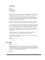
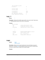
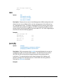
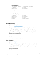
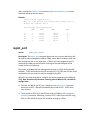
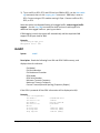
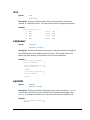
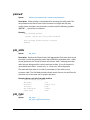
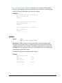
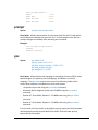
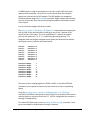
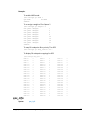
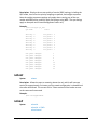
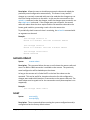
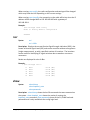
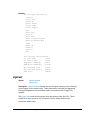
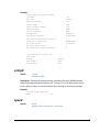
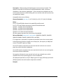
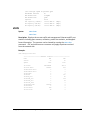
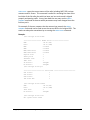
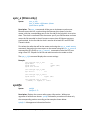
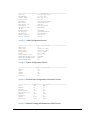
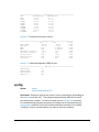
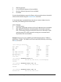
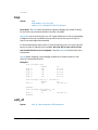
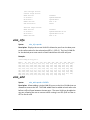
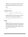
Giga Orion / Lynx Command Line Interface Guide This Appendix provides a standalone guide to the commands available through the Telnet, SSH, and console port of the Giga Orion and Giga Lynx. This CLI Reference is valid for Firmware Version 1.1.0 Command Keying Overview Key Functions Tab ‐ Autocomplete Completes a partial command name entry. When you enter a unique string of characters that is part of the command and press the Tab key, the system completes the command name. If you enter characters that could indicate more than one command, the system will display ”ambiguous command”. Enter a question mark (?) immediately following the partial command (no space). The system provides a list of commands that begin with that string. Del or Backspace Erases the character to the left of the cursor. Return At the command line, pressing the Return key performs the function of processing a command. At the –More‐‐ prompt on a terminal screen, pressing the Return key scrolls down to show the rest of the information. Space Bar Allows you to see more output on the terminal screen. Press the space bar when you see the More prompt on the screen to display the next screen. Left Arrow Moves the cursor one character to the left. Right Arrow Moves the cursor one character to the right. Up Arrow Recalls commands in the history buffer, beginning with the most recent command. Repeat the key sequence to recall successively older commands. Trango Systems, Inc. Giga Orion / Lynx Command Reference v 1.0.1 1 Down Arrow Return to more recent commands in the history buffer after recalling commands with the Up Arrow or Ctrl‐P. Repeat the key sequence to recall successively more recent commands. Different Node Levels View Node This is the default node the users log in. This is strictly for viewing configuration and statistics only. No configuration changes can be made at this level. Config Node Users can enter this node by typing in the command “config” from the view node. They will be prompted for a password and after successful authentication users enters the config mode. All configuration settings can be changed here. •
Most commands entered without any parameters will return the current configured values and are similar to “view” node. •
All configuration changes are applied immediately and don’t require any reboot except for the date command, after which a reboot must be done. •
All configuration changes have to be saved in order to be persistent across reboot. A single config save command will save all configuration changes made during the session. •
Users can go back to the “view” node by typing in the command exit Debug Node This node is additional management port related settings and users enter the debug node, by typing in the debug command from the config node. Users can re‐enter the view node by entering the cli command from within the debug node. Trango Systems, Inc. Giga Orion / Lynx Command Reference v 1.0.1 2 Individual Command Detailed Descriptions This section describes all the commands in detail for all nodes. acm Syntax: acm acm mod <modulation> <mse degrade> acm mod <modulation> <mse improve> Description: The acm command with no argument displays the status of the Adaptive Coding and Modulation (ACM) downshift and upshift thresholds for each modulation. The thresholds are displayed for all modulations regardless of the currently set min and max modulation. The acm mod <modulation> <mse improve in dB> command will allow the user to change the mse threshold at which the acm engine will upshift to the next higher modulation. Improvement thresholds are valid only up to the next to highest modulation level. The acm mod <modulation> <mse degrade in dB> command will allow the user to change the mse threshold at which the acm engine will downshift to the next lower modulation. Degrade thresholds are valid only down to the next to lowest modulation level. Valid modulations levels are qpsk, 8psk, qam16, qam32, qam64, qam128, qam256, qam512, and qam1024. When setting the ACM thresholds it is important to ensure that the degrade threshold is at least 3 dB lower than the improve threshold to prevent instability. In most applications the default values will be sufficient. However, if a more conservative approach is desired, lowering the mse thresholds can provide earlier downshifting when conditions start to degrade. ACM will allow the radio to automatically downshift to lower, more robust modulations as temporary channel degradation occurs, based on the MSE of the receiver. When the receiver detects the receive MSE passing a pre‐defined threshold, it will send a highly robust BPSK coded message to the far end telling the far end to switch its transmit modulation to the next level down. Trango Systems, Inc. Giga Orion / Lynx Command Reference v 1.0.1 3 NOTE: If the min and max modulation are set to the same, the thresholds are not used and have no meaning. ACM operation is not symmetric and each end of the link may be operating at a different modulation level based on the channel conditions (RSSI, MSE). Example: (changing the default degrade level for QAM1024 from ‐35.2 to ‐36 (CLI (CLI-config)# acm mod qam1024 mse_de -36
ACM modulation 1024QAM
MSE Degrade threshold set to -36.00
SUCCESS
(CLI-config)# acm
<======================== ACM status ======================>
ACM mod
MSE(improve)
MSE(degrade)
QPSK
-19.00
N/A
8PSK
-20.00
-17.00
16QAM
-22.90
-19.00
32QAM
-25.60
-21.90
64QAM
-28.20
-24.60
128QAM
-31.40
-27.20
256QAM
-33.70
-30.40
512QAM
-36.20
-32.70
1024QAM
N/A
-35.20
(CLI-config)#
alarms Syntax: alarms alarms 1 <on|off> alarms 2 <on|off> Description: The alarms command with no argument displays the status of the alarm inputs on the DB9 connector. The alarms may be forced on or off using the alarms 1 <on|off> command. For details on the DB9 pinout, see the user manual. atpc Syntax: atpc atpc enable <on|off> atpc max_power <modulation> <transmit power> Trango Systems, Inc. Giga Orion / Lynx Command Reference v 1.0.1 4 Description: The atpc enable <on|off> command enables the Automatic Transmit Power Control loop, which changes the allowable maximum transmit power level based on the current modulation level and target RSSI. ATPC works in conjunction with ACM, such that upon a shift to a lower modulation the transmitter will increase the transmitter power to increase the system gain and maintain the link longer. Upon the modulation shifting up, the transmit power will be reduced to prevent overdriving the power amplifier in the radio. The ATPC algorithm runs on the receiver side of the link and monitors the current Receive Signal Level (RSL or RSSI). If the current RSSI is less than the user set target rssi (targetrssi command), the ATPC algorithm will send a command to the transmitting side of the link requesting an increase in the transmit power level. The requests will cease when the current RSSI reaches the targetrssi +/‐ 2 dB. It is recommended that the targetrssi be set to the same level at which the link normally operates to prevent the system from constantly sending unnecessary power increase/decrease requests. As an example – If the link when aligned is ‐
40 dBm with ATPC off, set the target RSSI to ‐40 dBm. The max transmit power levels are set for each modulation using the atpc max_power <modulation> <transmit power> command and will vary by frequency. Example: ((CLI-config)# atpc
ATPC Enable:
Target RSSI:
ATPC Max Power(QPSK):
ATPC Max Power(8PSK):
ATPC Max Power(Q16):
ATPC Max Power(Q32):
ATPC Max Power(Q64):
ATPC Max Power(Q128):
ATPC Max Power(Q256):
ATPC Max Power(Q512):
ATPC Max Power(Q1024):
on
-40.00
28.00
28.00
26.00
26.00
24.00
24.00
23.00
23.00
22.00 bootimage Syntax: Trango Systems, Inc. bootimage upgrade idu Giga Orion / Lynx Command Reference v 1.0.1 5 bootimage upgrade odu Description: The bootimage upgrade idu command takes firmware recently loaded via the FTP or TFTP service and saves it into the Current Image partition of the FLASH memory of the IDU. Any subsequent reboot of the unit will then make the new firmware effective. In addition, the Previous Image FLASH memory is overwritten with the last Image that was loaded into the radio and run. The bootimage upgrade odu command takes ODU firmware recently loaded via the FTP or TFTP service and loaded on to the ODU. The ODU will be automatically power cycled after the ODU image is successfully loaded. config Syntax: config export config import config remove config save config view Description: The config commands allow the configuration setup of the unit, including all operating variables which are stored in FLASH to be viewed, saved, removed, imported from an external file, or exported to an external file. Typically only the config save command will be needed to save changes made to system operating variables to FLASH memory. The config view command allows all the saved system variables to be viewed in text format. If many units need to be programmed with the same settings, the config file in ASCII format can be exported using the config export command followed by tftp transfer of the export_config.txt file. The export_config.txt file can be imported to another identical unit by tftp or ftp transfer of the file and subsequently using the config import command, which will write the new config file into non volatile memory. If the config file is somehow corrupted, the config remove command should be executed, followed by a reboot. The system will automatically create a new default config file upon reboot if the file is missing, allowing all the variables to be re entered by the user. Trango Systems, Inc. Giga Orion / Lynx Command Reference v 1.0.1 6 NOTE: The command reset config, while similar, will also reset the access passwords. Example: (CLI-config)# config view
ODU_Power:
1
Frequency_Tx:
11020.00
Frequency_Duplex:
490.00
Tx_Power:
23.00
Opmode:
on
ATPC_Enable:
0
ATPC_Max_Power_QPSK:
20.00
ATPC_Max_Power_8PSK:
20.00
ATPC_Max_Power_Q16:
20.00
ATPC_Max_Power_Q32:
19.00
ATPC_Max_Power_Q64:
18.00
ATPC_Max_Power_Q128
17.00
ATPC_Max_Power_Q256:
16.00
ATPC_Max_Power_Q512:
15.00
ATPC_Max_Power_Q1024:
15.00
Target_RSSI:
-40.00
Httpd:
on
Snmpd:
on
Telnetd:
on
HC_Enable:
1
PLA_Type:
off
XPIC_Enable:
off
Speed_Mod_Max:
1024QAM
Speed_Mod_Min:
QPSK
Speed_Bandwidth:
60
QPSK_Improve:
-19.00
Q8PSK_Improve:
-20.00
QAM16_Improve:
-22.90
QAM32_Improve:
-25.60
QAM64_Improve:
-28.20
QAM128_Improve:
-31.40
QAM256_Improve:
-33.70
QAM512_Improve:
-36.20
QAM1024_Improve:
0.00
QPSK_Degrade:
0.00
Q8PSK_Degrade:
-17.00
QAM16_Degrade:
-19.00
QAM32_Degrade:
-21.90
QAM64_Degrade:
-24.60
QAM128_Degrade:
-27.20
QAM256_Degrade:
-30.40
QAM512_Degrade:
-32.70
QAM1024_Degrade:
-35.20
IBM_Enable:
off
IBM_Vlan_ID:
100
IBM_Tagging:
off
IBM_Port:
2
SYNC_E_MODE:
0
ETH1_Enable:
on
ETH1_Auto_Nego:
on
ETH1_Duplex:
full
ETH1_Pause_Frame:
off
ETH1_Speed:
1000
ETH1_Max_Rate:
1000
ETH1_Priority:
0
Trango Systems, Inc. Giga Orion / Lynx Command Reference v 1.0.1 7 ETH2_Enable:
ETH2_Auto_Nego:
ETH2_Duplex:
ETH2_Pause_Frame:
ETH2_Speed:
ETH2_Max_Rate:
ETH2_Priority:
QOS_Mode:
QOS_DSCP_Mode:
QOS_Priority0_Queue:
QOS_Priority1_Queue:
QOS_Priority2_Queue:
QOS_Priority3_Queue:
QOS_Priority4_Queue:
QOS_Priority5_Queue:
QOS_Priority6_Queue:
QOS_Priority7_Queue:
QOS_Queue0_Weight:
QOS_Queue1_Weight:
QOS_Queue2_Weight:
QOS_Queue3_Weight:
QOS_Queue4_Weight:
QOS_Queue5_Weight:
QOS_Queue6_Weight:
QOS_Queue7_Weight:
QOS_ETH1_DSCP_0:
QOS_ETH1_DSCP_1:
QOS_ETH1_DSCP_2:
QOS_ETH1_DSCP_3:
QOS_ETH1_DSCP_4:
QOS_ETH1_DSCP_5:
QOS_ETH1_DSCP_6:
QOS_ETH1_DSCP_7:
QOS_ETH1_DSCP_8:
QOS_ETH1_DSCP_9:
QOS_ETH1_DSCP_10:
QOS_ETH1_DSCP_11:
QOS_ETH1_DSCP_12:
QOS_ETH1_DSCP_13:
QOS_ETH1_DSCP_14:
QOS_ETH1_DSCP_15:
QOS_ETH1_DSCP_16:
QOS_ETH1_DSCP_17:
QOS_ETH1_DSCP_18:
QOS_ETH1_DSCP_19:
QOS_ETH1_DSCP_20:
QOS_ETH1_DSCP_21:
QOS_ETH1_DSCP_22:
QOS_ETH1_DSCP_23:
QOS_ETH1_DSCP_24:
QOS_ETH1_DSCP_25:
QOS_ETH1_DSCP_26:
QOS_ETH1_DSCP_27:
QOS_ETH1_DSCP_28:
QOS_ETH1_DSCP_29:
QOS_ETH1_DSCP_30:
QOS_ETH1_DSCP_31:
QOS_ETH1_DSCP_32:
QOS_ETH1_DSCP_33:
QOS_ETH1_DSCP_34:
QOS_ETH1_DSCP_35:
QOS_ETH1_DSCP_36:
Trango Systems, Inc. on
on
full
off
1000
1000
0
0
0
0
1
2
3
4
5
6
7
1
3
6
9
12
15
18
21
0
0
0
0
0
0
0
0
0
0
1
0
1
0
1
0
0
0
2
0
2
0
2
0
0
0
3
0
3
0
3
0
0
0
5
0
5
Giga Orion / Lynx Command Reference v 1.0.1 8 QOS_ETH1_DSCP_37:
QOS_ETH1_DSCP_38:
QOS_ETH1_DSCP_39:
QOS_ETH1_DSCP_40:
QOS_ETH1_DSCP_41:
QOS_ETH1_DSCP_42:
QOS_ETH1_DSCP_43:
QOS_ETH1_DSCP_44:
QOS_ETH1_DSCP_45:
QOS_ETH1_DSCP_46:
QOS_ETH1_DSCP_47:
QOS_ETH1_DSCP_48:
QOS_ETH1_DSCP_49:
QOS_ETH1_DSCP_50:
QOS_ETH1_DSCP_51:
QOS_ETH1_DSCP_52:
QOS_ETH1_DSCP_53:
QOS_ETH1_DSCP_54:
QOS_ETH1_DSCP_55:
QOS_ETH1_DSCP_56:
QOS_ETH1_DSCP_57:
QOS_ETH1_DSCP_58:
QOS_ETH1_DSCP_59:
QOS_ETH1_DSCP_60:
QOS_ETH1_DSCP_61:
QOS_ETH1_DSCP_62:
QOS_ETH1_DSCP_63:
QOS_ETH2_DSCP_0:
QOS_ETH2_DSCP_1:
QOS_ETH2_DSCP_2:
QOS_ETH2_DSCP_3:
QOS_ETH2_DSCP_4:
QOS_ETH2_DSCP_5:
QOS_ETH2_DSCP_6:
QOS_ETH2_DSCP_7:
QOS_ETH2_DSCP_8:
QOS_ETH2_DSCP_9:
QOS_ETH2_DSCP_10:
QOS_ETH2_DSCP_11:
QOS_ETH2_DSCP_12:
QOS_ETH2_DSCP_13:
QOS_ETH2_DSCP_14:
QOS_ETH2_DSCP_15:
QOS_ETH2_DSCP_16:
QOS_ETH2_DSCP_17:
QOS_ETH2_DSCP_18:
QOS_ETH2_DSCP_19:
QOS_ETH2_DSCP_20:
QOS_ETH2_DSCP_21:
QOS_ETH2_DSCP_22:
QOS_ETH2_DSCP_23:
QOS_ETH2_DSCP_24:
QOS_ETH2_DSCP_25:
QOS_ETH2_DSCP_26:
QOS_ETH2_DSCP_27:
QOS_ETH2_DSCP_28:
QOS_ETH2_DSCP_29:
QOS_ETH2_DSCP_30:
QOS_ETH2_DSCP_31:
QOS_ETH2_DSCP_32:
QOS_ETH2_DSCP_33:
QOS_ETH2_DSCP_34:
Trango Systems, Inc. 0
5
0
7
0
0
0
0
0
7
0
7
0
0
0
0
0
0
0
7
0
0
0
0
0
0
0
0
0
0
0
0
0
0
0
0
0
1
0
1
0
1
0
0
0
2
0
2
0
2
0
0
0
3
0
3
0
3
0
0
0
5
Giga Orion / Lynx Command Reference v 1.0.1 9 QOS_ETH2_DSCP_35:
QOS_ETH2_DSCP_36:
QOS_ETH2_DSCP_37:
QOS_ETH2_DSCP_38:
QOS_ETH2_DSCP_39:
QOS_ETH2_DSCP_40:
QOS_ETH2_DSCP_41:
QOS_ETH2_DSCP_42:
QOS_ETH2_DSCP_43:
QOS_ETH2_DSCP_44:
QOS_ETH2_DSCP_45:
QOS_ETH2_DSCP_46:
QOS_ETH2_DSCP_47:
QOS_ETH2_DSCP_48:
QOS_ETH2_DSCP_49:
QOS_ETH2_DSCP_50:
QOS_ETH2_DSCP_51:
QOS_ETH2_DSCP_52:
QOS_ETH2_DSCP_52:
QOS_ETH2_DSCP_53:
QOS_ETH2_DSCP_54:
QOS_ETH2_DSCP_55:
QOS_ETH2_DSCP_56:
QOS_ETH2_DSCP_57:
QOS_ETH2_DSCP_58:
QOS_ETH2_DSCP_59:
QOS_ETH2_DSCP_60:
QOS_ETH2_DSCP_61:
QOS_ETH2_DSCP_62:
QOS_ETH2_DSCP_63:
Snmp_Trap_1:
Snmp_Trap_2:
Snmp_Trap_3:
Snmp_Trap_4:
Snmp_Trap_5:
Trap_IP_1:
Trap_IP_2:
Trap_IP_3:
Trap_IP_4:
Trap_IP_5:
RSSI_Min:
RSSI_Max:
RSSI_Action:
MSE_Min:
MSE_Max:
MSE_Action:
BER_Min:
BER_Max:
BER_Action:
FER_Min:
FER_Max:
FER_Action:
IDU_Temp_Min:
IDU_Temp_Max:
IDU_Temp_Action:
ODU_Temp_Min:
ODU_Temp_Max:
ODU_Temp_Action:
IN_Port_Util_Min:
IN_Port_Util_Max:
IN_Port_Util_Action:
OUT_Port_Util_Min:
Trango Systems, Inc. 0
5
0
5
0
7
0
0
0
0
0
7
0
7
0
0
0
0
0
0
0
0
7
0
0
0
0
0
0
0
0
0
0
0
0
0.0.0.0
0.0.0.0
0.0.0.0
0.0.0.0
0.0.0.0
-85.00
-20.00
none
-45.00
-15.00
none
0.00
-4.00
none
0.00
-4.00
none
-10.00
70.00
0
-40.00
58.00
0
0.00
100.00
none
0.00
Giga Orion / Lynx Command Reference v 1.0.1 10 OUT_Port_Util_Max:
OUT_Port_Util_Action:
Link_Down_Action:
Unit_ID:
GPS_Latitude:
GPS_Longitude:
GREEN_BUFFER:
VLAN1_INDEX0:
VLAN1_INDEX1:
VLAN1_INDEX2:
VLAN1_INDEX3:
VLAN1_INDEX6:
VLAN1_INDEX7:
VLAN1_INDEX8:
VLAN1_INDEX9:
VLAN1_INDEX12:
VLAN1_INDEX15:
VLAN1_INDEX18:
VLAN1_INDEX21:
VLAN1_INDEX21:
100.00
none
none
Trango GigaOrion
N
E
1000
00000002
00040000
00000002
00000010
00000100
FFFFFFFF
FFFFFFFF
00001FFF
00010000
00100000
01000000
10000000
10000000
custom_profile Syntax: custom_profile add custom_profile remove Description: The custom_profile add command allows the user to replace the current modem settings for a given speed (bandwidth) with a custom modem profile. Custom profiles can be used to implement non‐standard channel bandwidths (symbol rate), reduce traffic latency, increase coding strength/RX sensitivity, or change other modem parameters not modifiable using the standard management interface. The custom file is provided by Trango Systems and is loaded into the radio using FTP or TFTP. After the profile is loaded, the system software will check to see if a custom profile exists and will use it instead of the standard profile shipped with the radio, even through a reboot. Each Custom profile is specific to a single speed/XPIC combination, and include all modulation levels. The custom_profile remove command allows the user to remove all cutom profiles and revert to the standard profiles upon the next reboot or speed loading. Contact your Trango representative for more information. Example: (CLI-config)# custom_profile add
All custom profiles in /tmp are added to the system
Trango Systems, Inc. Giga Orion / Lynx Command Reference v 1.0.1 11 (CLI-config)# custom_profile remove
All custom binaries are removed from the system
date Syntax: date date <year> <month> <date> <hour> <min> Description: The date command with no argument displays the current date and time in 24 hr format. When the arguments are input, the system Real Time Clock (RTC) is updated. Currently there is no NTP server support on this system. The system time is incremented using local on‐board time references only, and may not be accurate over long periods of time. If accuracy is desired, a remote process to update the clock periodically should be created using SNMP. The date will be maintained through power interruptions up to 8 hours. IMPORTANT: There are system event timers that are using the real time clock so it is highly recommended that the radio be rebooted after the change is made. Example: (CLI-config)# date
<00-99> YEAR: <year> <month> <date> <hour> <min>
<cr>
(CLI-config)# date 13 02 13 16 22
Wed Feb 13 16:22:00 MST 2013
debug Syntax: debug Description: The debug command allows the user to enter the debug node which has special networking commands executed outside the normal operating application. To enter the debug node the user must be logged into the config node of the main application. Trango Systems, Inc. Giga Orion / Lynx Command Reference v 1.0.1 12 Once in the debug node the user may run ping and route commands to external network devices, as well as open ssh or telnet sessions with other radios or network devices to assist in troubleshooting. If IBM is enabled on both radios then it is possible to telnet into the far side radio using the telnet command from within the debug node. To exit from the debug node back into the main application, the command cli should be used. To completely exit the debug node the exit command can be used. Example: (CLI-config)# debug
debug>
diagnostic Syntax: diagnostic Description: The diagnostic command is used to check low level connections and files and then generate a file that can be used by Trango support personnel. It should be run when instructed by Trango personnel during troubleshooting. Example: (CLI-config)# diagnostic
Checking all necessary system files........
Getting first snapshot of counters........
Getting device versions........
Checking FPGA connection........
Checking Modem connection........
Checking PIC connection........
Checking switch connection........
Getting ODU information........
Getting timer information........
Getting second snapshot of counters........
PASSED
PASSED
PASSED
PASSED
PASSED
PASSED
PASSED
PASSED
PASSED
PASSED
dscp_info Syntax: dscp_info < port# > where 1= GE1, 2=GE2, 3=GE3, and 4=GE4 Description: The dscp_info < port# > command is used to display the current diffserv code point to priority mappings. Code points are mapped to priorities, which are mapped to queues. The actual mappings are set using the qos dscp_source command. Priority to queue mappings are set using the qos cos_queue command. Note DSCP qos is disabled at ship time. To enable DSCP quality of service run the qos dscp_enable on command on both ends of the link. Example: The example shows the default dscp mappings for port GE1 Trango Systems, Inc. Giga Orion / Lynx Command Reference v 1.0.1 13 (CLI-config)# dscp_info 1
DSCP 1:
0
DSCP
DSCP 4:
0
DSCP
DSCP 7:
0
DSCP
DSCP 10:
1
DSCP
DSCP 13:
1
DSCP
DSCP 16:
1
DSCP
DSCP 19:
1
DSCP
DSCP 22:
2
DSCP
DSCP 25:
2
DSCP
DSCP 28:
2
DSCP
DSCP 31:
3
DSCP
DSCP 34:
3
DSCP
DSCP 37:
3
DSCP
DSCP 40:
4
DSCP
DSCP 43:
4
DSCP
DSCP 46:
5
DSCP
DSCP 49:
5
DSCP
DSCP 52:
6
DSCP
DSCP 55:
6
DSCP
DSCP 58:
7
DSCP
DSCP 61:
7
DSCP
2:
5:
8:
11:
14:
17:
20:
23:
26:
29:
32:
35:
38:
41:
44:
47:
50:
53:
56:
59:
62:
0
0
0
1
1
1
2
2
2
2
3
3
3
4
4
5
6
6
7
7
7
DSCP
DSCP
DSCP
DSCP
DSCP
DSCP
DSCP
DSCP
DSCP
DSCP
DSCP
DSCP
DSCP
DSCP
DSCP
DSCP
DSCP
DSCP
DSCP
DSCP
DSCP
3:
6:
9:
12:
15:
18:
21:
24:
27:
30:
33:
36:
39:
42:
45:
48:
51:
54:
57:
60:
63:
0
0
0
1
1
1
2
2
2
3
3
3
3
4
4
5
6
6
7
7
7
exit Syntax: exit Description: Exit the current management node. If user is logged into the config node, exit will take the user back to the view node. If user is in the debug node, exit will close the session. freq Syntax: freq freq <tx freq in MHz> Description: The freq command will set the RF transmit frequency of radio, as well as the RF receiver frequency which is determined by the following equation: rx freq = tx freq + freq_duplex when ODU subband suffix is “A” rx freq = tx freq ‐ freq_duplex when ODU subband suffix is “B” The ODU subband can be determined by viewing the ODU label or running the model command. TX center frequencies are determined based on regulatory agency and subject to the following restrictions: 1) The Min and max frequency allowed is set by the ODU model and can be viewed using the model command. Trango Systems, Inc. Giga Orion / Lynx Command Reference v 1.0.1 14 2) The minimum resolution of the freq command is .25 MHz . Frequencies are programmed in MHz using a decimal format . See example for more information The transmitter is muted before changing the transmitter frequency to avoid potential interference to adjacent channels during synthesizer reprogramming. If no argument is included the command will return the current frequency settings. Example: (CLI-config)# freq 11020.25
Tx Freq:
11020.25 (MHz)
Rx Freq:
11510.25 (MHz)
Freq Duplex:
490.00 (MHz)
freq_duplex Syntax: freq_duplex freq_duplex <duplex in MHz> Description: The freq_duplex command specifies a custom frequency duplex which will be used to calculate and load the RX frequency after the freq command is run. Only certain ODU models support a custom Frequency duplex and in general this command will not be required since the ODU is already programmed. If a nonstandard frequency duplex, or TR spacing is to be used, this command should be executed before the freq command to ensure correct TX and RX frequency programming. CAUTION: Upon running the freq_duplex command, the RX frequency will be reprogrammed, possibly causing a link down condition. Refer to the User Manual or Quick Start Guide to see the recommended freq_duplex settings for best frequency reuse. Example: (CLI-config)# freq_duplex 500
Freq Duplex:
500.00 (MHz)
ftp Syntax: Trango Systems, Inc. ftp <server IP Address> <user name> Giga Orion / Lynx Command Reference v 1.0.1 15 Description: This command allows any file to be retrieved from an FTP server and loaded onto the radio. Entering the ftp server IP address and user name will prompt the user for the password, which is provided by the administrator of the FTP site. After entering the password, the ftp> prompt will be displayed and the following ftp commands can be run: ftp> get <file_name> ‐ get the file from the ftp server. ftp> mode <mode> ‐ default is passive ftp> put <file_name> ‐ perform the ftp put command to put a file from the radio onto the FTP site ftp> logout – log out of the current session gps_info Syntax: gps_info Description: Displays the gps coordinates entered by the user for the radio. The coordinates are available via SNMP for mapping applications. There is no GPS unit inside the radio, so the user must enter these coordinates manually using the gps_lat and gps_long commands. Example: (cli-config)# gps_info
GPS Latitude:
GPS Longitude:
N 00 00.00
S 00 00.00
gps_lat Syntax: gps_lat <text string> Description: Allows the user to set the GPS latitude for the radio for retrieval via SNMP Managers for mapping purposes. The field is a text string which supports several different formats. Example: (cli-config)# gps_lat N 12 34.567
GPS Latitude:
N 12 34.567
GPS Longitude:
S 00 00.00
gps_long Syntax: Trango Systems, Inc. gps_long <text string> Giga Orion / Lynx Command Reference v 1.0.1 16 Description: Allows the user to set the GPS longitude for the radio for retrieval via SNMP Managers for mapping purposes. The field is a text string which supports several different formats. Example: (cli-config)# gps_long S 12 34.567
GPS Latitude:
N 12 34.567
GPS Longitude:
S 12 34.567
green_buff Syntax: green_buff <500‐8000> Description: Allows setting the packet buffer size in kBytes for all the QoS Queues. Feature Description: Larger buffer size settings will support bursty traffic and better TCP performance over networks with high latency. Longer latency and higher latency jitter over the radio link may occur with higher buffer size settings. The default setting for this parameter is 2000, or 2 Mbytes. Example: (CLI-config)# green_buff 8000
Green Buffer:
8000 kbytes
SUCCESS hc_enable Syntax: hc_enable hc_enable <on|off> Description: Displays the current status of the multilayer header compression feature and allows turning header compression on and off. Feature Description: Multilayer Header Compression is a powerful feature of the system. By removing redundant Ethernet L1‐L4 packet header information and replacing them with small tags before transmission over the air, real L2 Ethernet capacity can be significantly increased. At the other end of the link the original header information is replaced before egress out the Ethernet port. The following header combinations are compressed by the system: L2 (MAC) IPV4 VLAN VLAN+IPV4 Trango Systems, Inc. Giga Orion / Lynx Command Reference v 1.0.1 17 VLAN+IPV4+UDP VLAN+IPV4+TCP IPV6 VLAN+IPV6 VLAN+IPV6+UDP VLAN+IPV6+TCP The performance of the Header Compression is not dependent on the content of the packets, but rather on the packet size. For small packets, the L2 capacity increase is significant since so much of the packet is comprised of header information. For larger packets the improvement will be less since the header portions are a smaller percentage of the overall packet. The actual benefit can be monitored using the hc_stats command. There are two engines that are used to process the incoming data, one primarily for layer 2 compression, and the other for layer 3 and layer 4 compression. For L2‐L4 compression done by the two engines, up to 2048 flows can be stored. Flows are defined as a stream of packets where each packet has the same MAC or IP Source and Destination address. As the flows disappear from the traffic entering the radio Ethernet port, they are automatically aged out to allow room for new flows. In addition, higher capacity flows have priority over lower capacity flows. All packets will have the L1 inter‐frame gap and preamble removed prior transmission and the number of flows is not limited in this case. The user does not need to make any adjustments to the header compression feature as it is fully automatic. Example: (cli-config)# hc_enable
HC Enable:
on
hc_stats Syntax: hc_stats Description: Displays the current statistics for the header compression engines, including the number of flows currently active and the percentage improvement. The L2 and L3 thresholds shown are age out times in milliseconds. Age out times are automatic and cannot be changed by the user. Example: Trango Systems, Inc. Giga Orion / Lynx Command Reference v 1.0.1 18 (CLI-config)# hc_stats
HC Enable:
on
L2 Flow Count:
L3 Flow Count:
L2 Threshold:
L3 Threshold:
Net Compression Percent:
Gross Compression Percent:
1
1
1000
1000
4
4
help / ? Syntax: ? Description: Displays all available commands for the current node. Simply enter a “?” followed by the return for a full list of commands Example: (CLI-config)#?
acm
acs
bootimage
Display ACM feature status
Display ACS feature status
Upgrade/Toogle system firmware
.
.
.
version
voltage
xpic
xpic_stats
Display system software version
Read voltage values
XPIC configuration
Display XPIC statistics
httpd Syntax: httpd httpd <on|off> Description: Displays the current http daemon status and allows turning the daemon off. Turning httpd off will prevent access to the radio via web browser, so exercise caution when turning off and saving changes. Example: Trango Systems, Inc. Giga Orion / Lynx Command Reference v 1.0.1 19 (CLI-config)# httpd off
Httpd:
off
ibm Syntax: ibm ibm enable <on|off> ibm tagging <on|off> ibm vlanid <2‐4088> Description: Displays the current In‐band Management (IBM) configuration and allows the user to turn IBM on/off or set the management of the radio unit up on a management VLAN. To enable a management VLAN, the user must set the VLAN ID first, then enable the tagging. All traffic coming into the IBM port with the set VLAN ID will be forwarded to the local radio CPU. All Traffic originating at the CPU will have the VLAN tag applied. Example: (CLI-config)# ibm
IBM Enable:
IBM Tagging:
IBM Vlan ID:
IBM Port:
off
off
100
GE2
ipconfig Syntax: ipconfig ipconfig gateway <gateway ip address> ipconfig ip (ip address subnet mask> Description: With no argument the ipconfig command displays the current ip configuration radio unit and the MAC address. The default ip for the radio is 192.168.100.100 and should be changed along with the gateway before installation. The example below shows how to change the IP address and gateway. Changes are made permanent in FLASH after the setting without running the config save command. Example: Trango Systems, Inc. Giga Orion / Lynx Command Reference v 1.0.1 20 Change the IP address: (CLI-config)# ipconfig ip 10.14.0.6 255.255.254.0
IP Address:
10.14.0.6
Subnet Mask:
255.255.254.0
Gateway IP:
192.168.100.1
ETH MAC:
00:01:de:72:23:71
Change the gateway: (CLI-config)# ipconfig gateway 10.14.0.1
IP Address:
10.14.0.6
Subnet Mask:
255.255.254.0
Gateway IP:
10.14.0.1r
ETH MAC:
00:01:de:72:23:71
L2_age_timer Syntax: l2_age_timer l2_age_timer <0‐86400> Description: The l2_age_timer command allows setting of the internal switch MAC table ageout period. The default is 1800 seconds (30 minutes). The valid range is from 0 to 86400 seconds (24 hrs). If set to 0, the switch will not learn and incoming packets will flood to all ports. It is highly recommended that the age timer be set to a value higher than the external network switch, which is generally in the 4‐5 minute range. Example: ((CLI-config)# link_history
link_history Syntax: link_history Description: The link_history command shows how many times since reboot the radio link has unlocked and relocked. This command also shows the Link steady indicator, which will be 0 if the link has not been locked for more than a minute and 1 if the link has been locked for over a minute. These metrics are used for diagnostic purposes only. Example: Trango Systems, Inc. Giga Orion / Lynx Command Reference v 1.0.1 21 ((CLI-config)# link_history
Link History:
3
Link Steady:
1
linktest Syntax: linktest <1‐99> Description: linktest is a diagnostic command used to see the current RSL, MSE, BER and transmit/receive modulation levels over time. The linktest command is entered with a number of iterations which are each 1 second apart. This command will block any other changes to the radio unit, and cannot be interrupted after being started. Example: (CLI-config)# linktest 5
LOCK
RSSI
1>
1
-42.00
2>
1
-42.00
3>
1
-42.00
4>
1
-42.00
5>
1
-42.00
MSE
-40.30
-40.30
-39.80
-40.40
-40.20
BER
0.00E+00
0.00E+00
0.00E+00
0.00E+00
0.00E+00
Tx
1024QAM
1024QAM
1024QAM
1024QAM
1024QAM
Rx
1024QAM
1024QAM
1024QAM
1024QAM
1024QAM
loglevel Syntax: loglevel <0 1 2> Description: Displays the syslog log levels and allows them to be changed. Log level 0 records only changes made by the user via web, snmp, or CLI. Level 2 records Events such as threshold violations, ACS/ACM downshifts and upshifts. Level 3 records statistics such as RSSI, MSE, BER and capacity utilization every 1 minute. It is recommended that only log level 0 and 1 be used unless the user is trying to diagnose a problem since the syslog will fill up more quickly. To reduce the number of Level 3 events in the syslog, the log_timer command can be used to increase the interval between entries for Level 3 statistics. The syslog can hold 3000 entries in RAM. Example: Trango Systems, Inc. Giga Orion / Lynx Command Reference v 1.0.1 22 (CLI-config)# loglevel 0 1
Syslog level = 0 1
log_timer Syntax: log_timer <1‐30> Description: Allows changing the time between logging statistics when log level 3 is enabled. The default time is 1 minute and the timer can be set from 1‐ 30 minutes. It is recommended that the Level 3 logging only be used when trying to diagnose a problem to avoid filling up the syslog and potentially overwriting other events. Example: (CLI-config)# log_timer 15
Syslog Timer:
15 (minutes)
loopback_auto Syntax: loopback_auto <5‐120> show loopback_auto Description: loopback_auto is a diagnostic command that allows verification of the radio by transmitting and receiving at the same frequency within the same unit. The signal is transmitted through IF section of the IDU back to the receiver which allows verification that the transmitter and receiver are working properly. This command allows checking of the IDU only. In addition, this command will report the current Link Lock status, MSE and BER. The RSSI will vary depending on the transmit power level but as a reference for a 0 dBm set power, the RSSI should be in the ‐40 to ‐50 dBm range and the MSE should be better than ‐36 dB when the LINK indicator=1 NOTE: This command will break the RF link and stop user service to the far end of the link, so exercise caution before use. Also it is recommended that only a small number of iterations be performed to avoid losing the management connection When in operation, the Ethernet ports are blocked to prevent traffic from looping back the Ethernet port and forming a loop, so management of the radio may be temporarily lost if IBM is being used. Trango Systems, Inc. Giga Orion / Lynx Command Reference v 1.0.1 23 After running the loopback_auto command, the show loopback_auto must be executed to display the test results Example: ((CLI-config)# loopback_auto 5
Wait for a few minutes then execute show loopback_auto to
display the loopback result
(CLI-config)# show loopback_auto
LINK
RSSI
MSE
1>
2>
3>
4>
5>
1
1
1
1
1
-43.00
-43.00
-43.00
-43.00
-43.00
-40.70
-40.50
-40.80
-41.10
-41.10
BER
0
0
0
0
0
mgmt_port Syntax: mgmt_port < port# > Description: The mgmt_port command allows the user to select which port will be used for radio management (IBM or OBM). When IBM is enabled, traffic can flow through the link on the same port. If IBM is off, the management port is essentially an OBM port and all traffic entering on the specified port will be routed to the local radio only. The system is shipped with the management port set to 1 (GE1‐RJ45) and IBM enabled). Traffic will flow over the link through GE1, GE2, GE3 and GE4 per VLAN membership, but the radio can only be managed using GE1. Below are the steps required to configure the various combinations of IBM and OBM. Note that each step assumes a starting point of IBM on GE1, the default configuration: 1) To move the IBM to the GE2 port, simply run the mgmt_port 2 command. Reconnect to GE2 ‐ IBM will immediately be moved to GE2. Traffic flows over all ports. 2) To run traffic on GE2, GE3, and GE4 only and run OBM on GE1, run the ibm enable off command. OBM only is now on GE1. Traffic flows over GE2 using RJ45, or GE3 and GE4 using an SFP modules running at 1 Gbps. Trango Systems, Inc. Giga Orion / Lynx Command Reference v 1.0.1 24 3) To run traffic on GE1, GE3, and GE4 and run OBM on GE2, run the ibm enable off command, then run the mgmt_port 2 command. OBM only is now on GE1‐ Connect using an SFP module running 1 Gbps. Connect traffic to GE1, GE3, or GE4. Note that radios are shipped allowing all untagged traffic, and no tagged traffic support . See the vlan_add command for detail on how to add support for additional vlan tagged traffic on port by port basis. If IBM tagging is used, the system will automatically add the required VLAN support to the port used for IBM. Example: (CLI-config)# mgmt_port
Management Port: GE1
model Syntax: model Description: Reads the following from IDU and ODU FLASH memory, and displays them for reference: IDU Model IDU Serial Number IDU Hardware ID number ODU Model ODU Serial Number Minimum Transmit Frequency Maximum Transmit Frequency Current Transmit/Receive Spacing (Frequency Duplex) If the ODU is powered off the ODU information will be displayed as N/A Example: (CLI-config)#model
IDU Model:
IDU Serial ID:
ODU Model:
ODU Serial ID:
HW ID:
Tx Freq Min:
Tx Freq Max:
Freq Duplex:
GIGAORION-IDU-1
7280371
HP1-18-1560-3B
R35120067
1
19260.00 (MHz)
19700.00 (MHz)
1560.00 (MHz))
Trango Systems, Inc. Giga Orion / Lynx Command Reference v 1.0.1 25 mse Syntax: mse mse <1‐99> Description: Displays the Mean Squared Error for the number of iterations entered, in 1 second intervals. This command is useful for diagnostic purposes. Example: (CLI-config)# mse 4
1> MSE
2> MSE
3> MSE
4> MSE
-40.50
-40.10
-40.00
-40.10
(dB)
(dB)
(dB)
(dB)
odupower Syntax: odupower odupower <on|off> Description: Displays and allows turning on the relay that controls the supply of the ‐48 VDC power to the Radio portion of the unit. ODU power must be on before any radio settings can be made or a link can be established. Example: (CLI-config)# odupower
ODU Power Enable:
on
(CLI-config)# odupower off
ODU Power Enable:
off
SUCCESS
(CLI-config)# odupower on
ODU Power Enable:
on
SUCCESS opmode Syntax: opmode opmode <on|off> Description: Displays and allows changing the state of the transmitter. opmode on turns the transmitter on at the last set transmit power and frequency and opmode off unlocks the transmitter PLL and turns the transmit amplifiers off. Example: (CLI-config)# opmode on
Opmode:
on
Trango Systems, Inc. Giga Orion / Lynx Command Reference v 1.0.1 26 passwd Syntax: passwd <new password> <repeat new password> Description: Allows setting a new password for entering the config node. The new password must be no more than 8 characters in length and may only contain lower and upper case characters, numbers and the following symbols: @#$%&*.‐_. Spaces are not allowed Example: (CLI-config)# passwd?
passwd Assign the config node password
(CLI-config)# passwd trango12 trango12
SUCCESS
pla_stats Syntax: pla_stats Description: Displays the Physical layer Link Aggregation (PLA) stats which show the mode, receive and transmit states, Alarm Indication, and cable state. Under normal operation the TX and RX states will indicate “both” indicating that both radio links are being used for transmit and receive data. If one of the paths is not available then either “master only” or “slave only” will be displayed. The cable will show down if no cable is connected or if the cable is not a crossover cable. The PLA Mode should indicate master for one unit and Slave for the other unit at the same site for proper operation. Example: Master unit with PLA cable problem ((CLI-config)# pla_stats
PLA Mode:
off
Rx State:
master only
Tx State:
both
AIS Condition:
normal
Cable Down:
down
pla_type Syntax: Trango Systems, Inc. pla_type pla_type <off|master|slave> Giga Orion / Lynx Command Reference v 1.0.1 27 Description: Allows setting or display of the radio unit PLA type. “Master” should be set for the radio units that carry traffic from the router or switch, and “slave” should be set for the radio unit connected to the Master PLA port via the crossover cable. Slave Units may only be managed via OBM and no traffic will flow across the link from any of the slave Ethernet interfaces. If PLA is not being used then the pla_type should be set to off. Example: ((CLI-config)# pla_type
PLA Type:
off
port Syntax: port eth < port# > auto_negotiate <on|off> port eth < port# > enable <on/off> port eth < port# > maxrate <0‐1000> port eth < port# > pause <on|off> port eth < port#> priority <0‐7> port eth <port# > speed <100|1000> Description: Allows setting the port characteristics for either all Ethernet Ports. All settings are done on a port basis where port eth 1 or port eth 2 xxxx commands apply to GE1 (RJ45) and GE2 (RJ45). The commands port eth 3 or port eth 4 xxxx commands apply to GE3 and GE4 (SFP). port eth < port#> auto_negotiate allows turning the port auto negotiation on or off and is defaulted to on. Note that GE3 and GE4 are fixed and autonegotiate cannot be turned off. This is the default configuration. port eth < port#> enable allows turning the port on or off and is defaulted to on. All ports are enabled in the default configuration. port eth < port#> maxrate <0‐1000> allows the user to limit the ingress traffic for the port to restrict capacity over the link. port eth < port#> pause <on|off> enables pause behavior at the port. This feature only applies to Gigabit Ethernet operation and will have no effect for connections running at 10 or 100 Mbps. port eth < port#> priority <0‐7> allows the user to assign a fixed priority for all incoming traffic that is not in a VLAN. The priority assigned will map the traffic into one of the 4 queues for Quality of Service. If left at the default value of 0, all untagged traffic will go to the lowest priority queue. Trango Systems, Inc. Giga Orion / Lynx Command Reference v 1.0.1 28 port eth < port#> speed <100|1000> allows the user to assign a fixed speed to the port. Auto negotiate must be turned off before running this command. Note that GE2 is fixed at 1000 Mbps and cannot be changed. Examples: CLI-config)# port eth 2 maxrate 500
Port 2 max rate: 500
SUCCESS
(CLI-config)# port eth 2 pause on
Port 2 pause frame: on
SUCCESS
(CLI-config)# port eth 2 priority 7
Port 2 priority: 7
SUCCESS
power Syntax: power power <0 to 30> ( varies by model) Description: Allows setting or displaying the ODU transmitter power in dBm. The max and min power levels are shown based on the model and these levels cannot be exceeded. Also, for higher modulations signal distortion, packet loss, and regulatory non compliance may occur if the power levels are set higher that the datasheet/ specification levels Changes will take effect immediately after setting. Example: (CLI-config)# power
Power:
Power Max:
Power ODU Min:
Power ODU Max:
Trango Systems, Inc. 22.00
22.00
5.00
28.00
Giga Orion / Lynx Command Reference v 1.0.1 29 (CLI-config)# power 17
Power:
Power Max:
Power ODU Min:
Power ODU Max:
17.00
22.00
5.00
28.00
prompt Syntax: prompt <new prompt label> Description: Allows customization of the prompt label for the CLI node which may be desired to identify the particular unit. In the example notice that the prompt changes immediately after executing the command. Example: (CLI-config)# prompt Woodson
SUCCESS
(Woodson-config)#
qos Syntax: qos mode <0‐3> qos cos_queue <0‐7> <0‐7> qos dscp_source < port#> > <0‐63> <0‐7> qos dscp_enable <on|off> qos weight <0‐7> <0‐49> Description: Allows display and changing of the quality of service (QOS) mode, queue weights, cos queue to priority mappings, and Diffserv to Priority mappings. The qos mode may be set to one of the following modes which control how packets are scheduled out from the 8 queues: ‐
All queues strict mode using the qos mode 0 command, ‐
All queues deficit weighted round robin (DWRR) using the qos mode 1 command. ‐
Queues 6‐7 Strict Mode, Queues 0 ‐ 5 DWRR mode using the qos mode 2 command ‐
Queues 4‐7 Strict Mode, Queues 0 ‐ 3 DWRR mode using the qos mode 3 command In strict mode, all of the traffic in the highest priority queues will be forwarded and the queue must be emptied before any traffic from the lower priority queues will be forwarded. Trango Systems, Inc. Giga Orion / Lynx Command Reference v 1.0.1 30 In DWRR mode, as long as the weights are non zero, some traffic from each queue will be forwarded ‐ the user has control of how often the individual queues are serviced via the QOS weights. The QOS weights are mapped to individual queues using the qos weight command. Higher weights will translate to more of the traffic from that priority being forwarded to the modem section of the system. In strict mode the weights will have no effect. The qos cos_queue <0‐7(Priority)> <0‐7(Queue)> command allows mapping the priority field of the received packet VLAN tag to one of the 7 queues in the switch portion of the radio. For strict mode Queue 7 is always the highest priority, with queues 6, 5, 4, 3, 2, 1, and 0 being decreasing priority. For weighted mode the weights assigned to each queue will dictate which queues have higher priority. Defaults are shown below: Priority 0: COS Queue = 0 Priority 1: COS Queue = 1 Priority 2: COS Queue = 2 Priority 3: COS Queue = 3 Priority 4: COS Queue = 4 Priority 5: COS Queue = 5 Priority 6: COS Queue = 6 Priority 7: COS Queue = 7 COS Queue 0 Weight: 1 COS Queue 1 Weight: 2 COS Queue 2 Weight: 4 COS Queue 3 Weight: 8 COS Queue 4 Weight: 12 COS Queue 5 Weight: 15 COS Queue 6 Weight: 18 COS Queue 7 Weight: 21 The same priority mapping applies for Diffserv traffic, as IP packet DS fields (codepoints) are mapped to the priority level and then to the corresponding queue. Using the qos dscp_source < port#> < 0‐63(Code Point) > < 0‐7(Priority)> command, the Diffserv code points in the DS field of an IP packet will be used to map the packet to a priority level from 0‐7. DSCP is configurable for each port 1 through 4 independently. To enable DSCP QoS mode, use the qos dscp_enable <on|off> command. Both ports are enabled or disabled with the single command Trango Systems, Inc. Giga Orion / Lynx Command Reference v 1.0.1 31 Example: To enable WRR mode: (CLI-config)# qos mode 1
QOS Mode:
All WRR
SUCCESS
To re assign a weight of 5 to Queue 2 (CLI-config)# qos weight 2 5
COS Queue 0 Weight:
COS Queue 1 Weight:
COS Queue 2 Weight:
COS Queue 3 Weight:
COS Queue 4 Weight:
COS Queue 5 Weight:
COS Queue 6 Weight:
COS Queue 7 Weight:
SUCCESS
1
2
5
8
12
15
18
21
To map DS codepoint 40 to priority 7 for GE2 (CLI-config)# qos dscp_source 2 40 7
To display DS codepoint mappings for GE2 (CLI-config)# dscp_info 2
DSCP 1:
0
DSCP 2:
0
DSCP 3:
0
DSCP 4:
0
DSCP 5:
0
DSCP 6:
0
DSCP 7:
0
DSCP 8:
0
DSCP 9:
0
DSCP 10:
1
DSCP 11:
0
DSCP 12:
1
DSCP 13:
0
DSCP 14:
1
DSCP 15:
0
DSCP 16:
0
DSCP 17:
0
DSCP 18:
2
DSCP 19:
0
DSCP 20:
2
DSCP 21:
0
DSCP 22:
2
DSCP 23:
0
DSCP 24:
0
DSCP 25:
0
DSCP 26:
3
DSCP 27:
0
DSCP 28:
3
DSCP 29:
0
DSCP 30:
3
DSCP 31:
0
DSCP 32:
0
DSCP 33:
0
DSCP 34:
5
DSCP 35:
0
DSCP 36:
5
DSCP 37:
0
DSCP 38:
5
DSCP 39:
0
DSCP 40:
7
DSCP 41:
0
DSCP 42:
0
DSCP 43:
0
DSCP 44:
0
DSCP 45:
0
DSCP 46:
7
DSCP 47:
0
DSCP 48:
7
DSCP 49:
0
DSCP 50:
0
DSCP 51:
0
DSCP 52:
0
DSCP 53:
0
DSCP 54:
0
DSCP 55:
0
DSCP 56:
7
DSCP 57:
0
DSCP 58:
0
DSCP 59:
0
DSCP 60:
0
DSCP 61:
0
DSCP 62:
0
DSCP 63:
0
qos_info Syntax: Trango Systems, Inc. qos_info Giga Orion / Lynx Command Reference v 1.0.1 32 Description: Displays the current quality of service (QOS) settings, including the QOS mode, class of service priority mappings to queues, and weight to queues. Note the weight to queue mappings only apply when running one of the qos modes with WRR active, and only apply the queues using WRR. The qos settings apply to data path and in band management traffic only. Example: ((CLI-config)# qos_info
QOS Mode:
strict
Priority
Priority
Priority
Priority
Priority
Priority
Priority
Priority
COS
COS
COS
COS
COS
COS
COS
COS
0:
1:
2:
3:
4:
5:
6:
7:
Queue
Queue
Queue
Queue
Queue
Queue
Queue
Queue
0
1
2
3
4
5
6
7
COS
COS
COS
COS
COS
COS
COS
COS
Weight:
Weight:
Weight:
Weight:
Weight:
Weight:
Weight:
Weight:
Queue
Queue
Queue
Queue
Queue
Queue
Queue
Queue
=
=
=
=
=
=
=
=
0
1
2
3
4
5
6
7
1
2
4
8
12
15
18
21
reboot Syntax: reboot Description: Allows the user to remotely reboot the unit, which will interrupt service for approximately 2 minutes until the saved configuration is reloaded and the radio reinitialized. The current SSH or Telnet session will be broken as soon as the command is executed. Example: (CLI-config)#reboot
reload Syntax: Trango Systems, Inc. reload in reload in <1‐240> reload cancel Giga Orion / Lynx Command Reference v 1.0.1 33 Description: Allows the user to schedule an automatic reboot and reload the previously saved configuration automatically. This feature is very useful if changes to a remotely connected radio are to be made but the change may run the risk of losing connection to the radio. In this case the user would run the reload in x command, make the changes, and if the changes were successful, run the reload cancel command. If the changes were not successful, the remote radio will reboot after the timer expires and the link would be restored to the known good condition, preventing a truck roll to the remote site. To periodically check how much time is remaining, the reload in command with no argument can be used. Example: (CLI-config)# reload in 10
Reload in 10 minutes. Less than 10 minutes remains
(CLI-config)# reload in
Reload in 10 minutes. Less than 9 minutes remains
(CLI-config)# reload cancel
Reload cancelled
remote reboot Syntax: remote reboot Description: This command allows the user to soft reboot the remote radio unit even if no IBM or OBM connection is available to the remote. The previously saved configuration will be loaded upon the reboot. As long as the remote unit is linked via RF to the local the reboot can be executed. This can be useful for situations where the far side configuration changes were made which break an IP connection to the remote radio unit. The word reboot must be typed out for the command to work (Autocomplete is not supported). Example: (CLI-config)# remote reboot
reset Syntax: reset config reset ipconfig Description: These commands allow resetting the system configuration and ip configuration back to factory default values. Trango Systems, Inc. Giga Orion / Lynx Command Reference v 1.0.1 34 When running reset config, the radio configuration and settings will be changed which may break the link depending on the current settings. When running reset ipconfig, the connection to the radio will be lost since the IP address will be changed back to 192.168.100.100 with a gateway of 192.168.100.1. Example: (CLI-config)# reset config
Reset to factory default configuration
SUCCESS
rssi Syntax: rssi rssi <1‐99> Description: Displays the current Receive Signal Strength Indication (RSSI), also known as Receive Signal Level (RSL) and can be run either without an argument (single measurement), or with a specified number of iterations. The iterations can be useful for identifying RF signal variations due to weather or antenna movement. Results are displayed in units of dBm. Example: (CLI-config)# rssi 5
1> RSSI
2> RSSI
3> RSSI
4> RSSI
5> RSSI
-41.00
-41.00
-41.00
-41.00
-41.00
(dB)
(dB)
(dB)
(dB)
(dB)
show Syntax: show history show loopback_auto show passwords Description: show history shows the last 20 commands that were executed on the system. show loopback_auto shows the results of running the loopback_auto command. show passwords shows all the CLI, SNMP and web passwords and is only available at the config login level. Trango Systems, Inc. Giga Orion / Lynx Command Reference v 1.0.1 35 Example: (CLI-config)# show history
linktest
status save
status pll
status remote
status modem
status compare
date
stats show
siglevel
stats show
speed 30 qam1024 qam16
speed 60 qam1024 qpsk
snmpd
snmpd off
snmpd on
siglevel
show
(CLI-config)# show passwords
CLI View node:
trango
CLI Config node:
trango
SNMP Read community:
public
SNMP Write community:
private
Web Interface View:
trango
Web Interface Config:
trango
Snmp Trap:
trapstr
siglevel Syntax: siglevel modem siglevel odu Description: siglevel modem displays the current signal statistics of the incoming receive signal at the modem input. These parameters are useful for diagnosing link signal degradation and should be used in consultation with Trango Tech Support. The siglevel odu command shows the alarm parameters from the ODU. These should all be zero except for the TX measure metric which measures the transmitter power level.
Trango Systems, Inc. Giga Orion / Lynx Command Reference v 1.0.1 36 Example: (CLI-config)# siglevel modem
IDU RSSI:
Ext AGC:
Normalized MSE:
Radial MSE:
LDPC Decoder Stress:
External AGC:
Carrier Offset:
Rx Symrate:
FEC Block Counter:
FEC Uncorrected Block Counter:
LDPC Avg Iterations:
Rx Total Bytes:
Rx Total Error Bytes:
Rx Total Error Bytes(working):
(CLI-config)# siglevel odu
ODU Info:
Alarm:
RPS Alarm:
Tx measure:
-13
0x0801
-391
-384
2731
2049
2991
52000240
2375919568
0
3285618494
775739338
0
0
0x0000
0x00
0x23
snmpd Syntax: snmpd snmpd <on|off> Description: Displays the simple network monitoring protocol (SNMP) daemon status and allows turning the daemon off. Turning snmpd off will prevent access to the radio via snmp, so exercise caution when turning off and saving changes. Example: (CLI-config)# snmpd off
Snmp:
off
speed
Syntax: Trango Systems, Inc. speed speed <ch bw> <max mod> <min mod> Giga Orion / Lynx Command Reference v 1.0.1 37 Description: Allows setting and displaying the current local unit speed. The speed is comprised of the channel occupied bandwidth in MHz, maximum modulation, and minimum modulation. If the max and min modulation are set to the same level then no ACM shifting will occur and the radio will remain at the set modulation always. Acceptable values are as follows: Channel Bandwidth (<ch bw>): 3, 4,5,7,8,10,12,14, 20, 25, 30, 40, 50, 60 MHz Notes: For ITU 55 and 56 MHz channels the speed 60 should be used. For ITU 27.5 and 28 MHz channels the speed 30 should be used. Speed 3 = 3.5 MHz channel bandwidth Speed 4 = 3.75 MHz channel bandwidth Speed 8 = 8.33 MHz channel bandwidth Speed 12= 12.5 MHz channel bandwidth All other speeds represent the actual channel bandwidth Min and Max Mod (<max mod>, <min mod>): QAM1024, QAM512, QAM256, QAM128, QAM64, QAM32, QAM16, 8PSK, and QPSK. If no argument is presented, the speed command will return the current speed information along with the symbol rate in Msym/sec, Set capacity in Mbps and current TX and RX capacity in Mbps. Current TX capacity represents the max rate that the local unit can transmit given the current transmit modulation. Current RX capacity represents the max rate that the local unit can receive given the current receive modulation. Set capacity indicates the max rate the local unit was originally set to which would be the normal operating point in most installations. All displayed capacities are Layer 2 Mbps is given for large (1518 byte) and small (64 byte) packet sizes with header compression enabled. Example: Trango Systems, Inc. Giga Orion / Lynx Command Reference v 1.0.1 38 (CLI-config)# speed 60 qam1024 qpsk
Bandwidth Current:
60
Max Modulation:
1024QAM
Min Modulation:
QPSK
Symrate:
49.50
Set Capacity (SM/LG):
761.00/486.00
Tx Capacity (SM/LG):
761.00/486.00
Rx Capacity (SM/LG):
761.00/486.00
(Mbps)
(Mbps)
(Mbps)
stats Syntax: stats show stats clear Description: Displays the current traffic and management Ethernet and RF port statistics including port counters, utilization, packet size statistics, and dropped frame information. The counters can be cleared by running the stats clear command. CRC and collision errors counters only apply to packets received from the network side. Example: (CLI-config)# stats show
<====================== Ethernet Counters ======================>
Port:
GE1
Status:
GE2
on
on
1000
1000
5542898064
91474
3651455
809
In Multicast Pkts:
0
0
In Broadcast Pkts:
0
0
In Discard:
0
0
In Pkt64:
0
547
In Pkt65_127:
0
42
In Pkt128_255:
0
204
In Pkt256_511:
0
16
In Pkt512_1023:
0
0
3652316
0
0
0
In Port Rate:
499
0
In Port Util:
49
0
Speed:
In Octets:
In Ucast Pkts:
In Pkt1024_1518:
In Pkt1519+:
Trango Systems, Inc. Giga Orion / Lynx Command Reference v 1.0.1 39 Out Octets:
5369465046
6420
3537199
16
Out Multicast Pkts:
0
0
Out Broadcast Pkts:
0
0
Out Discard:
0
0
Out Pkt64:
0
6
Out Pkt65_127:
0
5
Out Pkt128_255:
0
1
Out Pkt256_511:
0
0
Out Pkt512_1023:
0
0
3540515
4
0
0
Out Port Rate:
484
0
Out Port Util:
48
0
CRC Error:
0
0
Collision Error:
0
0
Out Ucast Pkts:
Out Pkt1024_1518:
Out Pkt1519+:
<======================== RF Counters ==========================>
IN
RF Octets:
RF Pkts:
Port Rate(Mbps):
Port Util(per):
OUT
1098093592
1288920020
3543436
3659199
485
500
99
102
status Syntax: status modem status pll status remote status save status compare Description: Displays various system status information as follows: status modem provides the current local MSE, RSSI, Bit Error Rate (BER) and Frame Error Rate (FER), modem locks and Transmit/Receive Modulation levels (Profiles). All data is an instantaneous snapshot of the link condition. status pll provides all transmit and receive Phase Locked Loop (PLL) status where 1 = locked (normal) and 0= unlocked (not normal). If N/A is shown then the PLL does not apply for that ODU model. status remote shows the current MSE, RSSI, Lock and RX profile status of the far end radio which is obtained via internal communication to the far end radio unit. Trango Systems, Inc. Giga Orion / Lynx Command Reference v 1.0.1 40 status save saves the current status of the radio including MSE, RSSI, various counters and PLL Status. This command is useful for recording the state of the local side of the link after the radio has been put into service and is aligned properly and passing traffic. At any later date the user may run the status compare command to observe which parameters may have changed since the link was put in. For example, if the user suspects that the antenna has moved, the status compare command can be used to see the current RSSI vs the original RSSI. The status can always be overwritten by re‐running the status save command. Example: (CLI-config)# status modem
<===================== Modem Status ====================>
MSE:
-39.80 (dB)
RSSI:
-38.00 (dBm)
BER:
0.00E+00
FER:
0.00E+00
BER(cumulative):
0.00E+00
FER(cumulative):
0.00E+00
Acquire Lock:
1
Timing Lock:
1
Preamble Lock:
1
LDPC Lock:
1
Tx Profile:
1024QAM
Rx Profile:
1024QAM
(CLI-config)# status pll
<========================= PLL Status ==========================>
ODU IF PLL:
1
ODU Tx PLL:
1
ODU Rx PLL:
1
IDU Tx Rx PLL:
1
(CLI-config)# status remote
MSE:
-38.09 (dB)
RSSI:
-39.00 (dBm)
Link Lock:
1
Rx Profile:
1024QAM
(CLI-config)# status save
All system status saved
Trango Systems, Inc. Giga Orion / Lynx Command Reference v 1.0.1 41 sync_e (Orion only)
Syntax: sync_e_info sync_e_mode <off|master |slave> synce source <port#> Description: The sync_e commands all the user to implement synchronous Ethernet across the link, synchronizing the Ethernet port chosen to be the master, with the corresponding port on the far side of the link which is set to be slave. The clock is recovered from the master sync‐E port PHY Receiver and sent across the link encoded in the air frames to ensure that all Ethernet ports are synchronized. At the far side the clock is used to drive both GE1 and GE2 PHY Transmit clocks. First select the radio that will be the master unit using the sync_e_mode master command. Next select the source port on the master using the sync_e_source 0 command for GE1 (RJ45) or sync_e_source 1 command to select the SFP port using a fiber SFP. Repeat for the far end radio but select the mode as slave. The sync_e_info command displays the current settings. Example: (CLI-config)# sync_e_info
SyncE Mode:
SyncE Source:
SyncE Lock Status:
off
copper (GE1)
on
(CLI-config)# sync_e_mode
Sync E Port:
off
(CLI-config)# sync_e_source
SyncE Source:
copper (GE1)
(CLI-config)# sync_e_source
[SOURCE] 0: Copper, 1: Fiber
sysinfo Syntax: sysinfo sysinfo <1‐7> Description: Displays the current radio system information. Without an argument all sections are shown. sysinfo followed by a number will show only the corresponding section according to the examples shown below sysinfo 1 – Management Information Section Trango Systems, Inc. Giga Orion / Lynx Command Reference v 1.0.1 42 <======================= 1. Management =====================>
Unit ID:
Trango Giga Orion
IP Address:
10.14.0.152
Subnet Mask:
255.255.255.0
Gateway IP:
10.14.0.1
ETH MAC:
00:01:de:6F:16:1A
IDU Model:
GIGAORION-IDU-1
IDU Serial ID:
7280154
ODU Model:
HP1-11-490-6A
ODU Serial ID:
R38115685
HW ID:
1
FPGA Version:
0024090D
OS Version:
2p6r22b0D092513
FW Version:
1p0r0D092513
Modem Version:
6201.5.36
ODU FW Version:
060211
sysinfo 2 – Radio Configuration Section <================= 2. Radio Configuration ==================>
ODU Power:
on
Freq (Tx):
11020.00 (MHz)
Freq (Rx):
11510.00 (MHz)
Freq Duplex:
490.00 (MHz)
Power:
23.0 (dBm)
Speed Symbol Rate:
49.50
Speed Max Modulation:
1024QAM
Speed Min Modulation:
QPSK
Speed Bandwidth:
60
sysinfo 3 – System Configuration Section <================ 3. System Configuration ==================>
Httpd:
on
PLA:
off
Snmpd:
on
Tftpd:
off
Telnetd:
on
sysinfo 4 – Ethernet Port Configuration Information Section <=============== 4. ETH Port Configuration =================>
Port:
GE1
GE2
Enable:
on
on
Status:
on
on
Pause Frame:
off
off
Auto Negotiate:
on
on
Duplex:
full
full
Priority:
0
0
Speed:
1000
1000
Max Rate:
1000
1000
sysinfo 5 – Adaptive Coding and Modulation (ACM) Section Trango Systems, Inc. Giga Orion / Lynx Command Reference v 1.0.1 43 <====================== 5. ACM status ======================>
ACM
MSE(improve)
MSE(degrade)
QPSK
-19.00
N/A
8PSK
-20.00
-17.00
16QAM
-22.90
-19.00
32QAM
-25.60
-21.90
64QAM
-28.20
-24.60
128QAM
-31.40
-27.20
256QAM
-33.70
-30.40
512QAM
-36.20
-32.70
1024QAM
N/A
-35.20
sysinfo 6 – Threshold Information Section <==================== 6. Threshold Info ====================>
min
max
action
RSSI (dBm):
-85.00
-20.00
none
MSE (dB):
-45.00
-15.00
none
BER:
N/A
0.00E+00
none
FER:
N/A
0.00E+00
none
IDU Temp (celsius):
-10.0
70.0
none
ODU Temp (celsius):
-40.0
58.0
none
IN Port Util:
N/A
100.0
none
OUT Port Util:
N/A
100.0
none
Link Down:
N/A
N/A
none
sysinfo 7 – In Band Management (IBM) Section <======================= 7. IBM Info =======================>
IBM Enable:
on
IBM Tagging:
off
IBM Vlan ID:
100
IBM Port:
GE1
syslog Syntax: syslog syslog <clear|export|0‐2> Description: Displays a log of all set actions, events, and statistics, depending on the loglevel set by the user. The syslog has approximately 3000 entries and is not saved across a reboot. To clear the syslog, use the syslog clear command. For troubleshooting and post processing, the syslog can be exported using the syslog export command. Once this command has been executed, a file named “syslog.txt” may be transferred from the radio to the host computer. Trango Systems, Inc. Giga Orion / Lynx Command Reference v 1.0.1 44 To view all events, run syslog with no argument. To view events only, run syslog 0. To view user set changes only, run syslog 1. To view statistics only, run the syslog 2 command. Example: (CLI-config)# syslog clear
(CLI-config)# syslog
Current 0:02:52:56.840)
targetrssi Syntax: targetrssi targetrssi <rssi in dBm> where rssi is from ‐88 to ‐25 Description: Allows display and setting of the target rssi which is used by the ATPC algorithm. If ATPC is enabled using the atpc enable on command, the radio unit will send power up and down requests to the far end radio to attempt to remain within +/‐ 2 dB of the target RSSI level. If ATPC is disabled, the targetrssi is not used. Example: (CLI-config)# targetrssi -35
Target RSSI:
-35.00
telnetd Syntax: telnetd telnetd <on|off> Description: Displays the current telnet daemon status and allows turning the daemon off. Turning telnetd off will prevent access to the radio via telnet, so exercise caution when turning off and saving changes. Example: (CLI-config)# telnetd off
Telnetd:
off
temp Syntax: temp Description: Displays the current IDU and ODU temperatures in degrees C. These values are read from internal temperature sensors and will always be 10‐
30 degrees higher than the ambient temperature. Trango Systems, Inc. Giga Orion / Lynx Command Reference v 1.0.1 45 The temp values should be used to spot unusual temperature changes which may indicate poor airflow around the radio. If thresholds are set to trigger action based on temperature, ensure that this offset is considered. Example: (Taken with outside air of approximately 25 deg C) (CLI-config)# temp
IDU Temperature:
ODU Temperature:
53
37
(celsius)
(celsius)
tftpd Syntax: tftpd tftpd <on | off> Description: The tftpd command without any argument displays the current status of the trivial file transfer protocol (tftp) server in the radio. tftpd on turns the server on to allow firmware upgrades or transfer of files to and from the radio internal RAM. It is recommended to keep the tftp server off during normal operation. Example: (cli-config)# tftpd
Tftpd:
off
(cli-config)# tftpd on
Tftpd:
on
threshold Syntax: threshold threshold action <0‐8 (threshold)> <0‐2 (action)> threshold value <0‐8 (threshold)> <min | max> <value> Description: The threshold command allows individual link parameters to be internally monitored against user set thresholds. If the thresholds are violated, an action can be assigned to either notify an external network monitoring program or take action on the data path of the link. The following thresholds can be set: Threshold Mapping: 0 RSSI 1 MSE 2 BER 3 FER 4 IDU Temperature Trango Systems, Inc. Giga Orion / Lynx Command Reference v 1.0.1 46 5 ODU Temperature 6 In Port Utilization (percent of max available) 7 Out Port Utilization (percent of max available) 8 Link Down For each threshold above, except Link Down, minimum and maximum threshold values can be entered using the threshold value command. If a threshold value is exceeded (lower than the min value or higher than the max value), the following actions can be taken: Action Mapping: 0
none (no action) 1
snmp trap is generated and sent to all trap IP Addresses that are enabled 2
RPS – Rapid Port Shutdown of the datapath for 30 seconds to prevent RSTP. This blocking is done on both ends of the link to allow layer 2 path switching using STP or RSTP protocols running on a connected switch. Physical ports are not shutdown. Example: Shows how to set an SNMP trap for RSSI dropping below ‐75 dBm or going above ‐15 dBm. The SNMP trap IP must have been previously set up using the trap command. ((CLI-config)# threshold
min
RSSI (dBm):
-85.00
MSE (dB):
-45.00
BER:
N/A
FER:
N/A
IDU Temp (celsius):
-10.0
ODU Temp (celsius):
-40.0
IN Port Util:
N/A
OUT Port Util:
N/A
Link Down:
N/A
max
-20.00
-15.00
0.00E+00
0.00E+00
70.0
58.0
100.0
100.0
N/A
action
none
none
none
none
none
none
none
none
none
(cli-config)# threshold action 0 1
Threshold 0:
min=-85.00, max=-20.00, action=snmptrap
SUCCESS
(cli-config)# threshold value 0 min -75
Threshold 0:
min=-75.00, max=-20.00
SUCCESS
(cli-config)# threshold value 0 max -15
Threshold 0:
min=-75.00, max=-15.00
Trango Systems, Inc. Giga Orion / Lynx Command Reference v 1.0.1 47 SUCCESS
trap Syntax: trap trap enable <1‐5> <on |off> trap ip <1‐5> <IP Address in A.B.C.D format> Description: The trap command with no argument displays the saved IP config for the each trap and shows whether the trap is enabled. trap enable turns on each trap on or off. A trap will be sent to the corresponding IP address if the trap is enabled. No trap will be sent if the trap is off. Up to 5 trap IPs can be assigned and enabled. If a threshold violation with action= 1 (send snmptrap) occurs, an snmp trap will be sent to each IP address that is enabled. No traps will be sent unless at least one threshold action is set to snmptrap. See the threshold command for more information. trap ip allows assigning a trap manager ip address to send the trap to in the event of a threshold violation. Examples: (CLI-config)# trap
Enable
Trap 1:
off
Trap 2:
off
Trap 3:
off
Trap 4:
off
Trap 5:
off
IP
0.0.0.0
0.0.0.0
0.0.0.0
0.0.0.0
0.0.0.0
(CLI-config)# trap ip 1 192.168.0.1
Enable
IP
Trap 1:
off
192.168.0.1
SUCCESS
(CLI-config)# trap enable 1 on
Enable IP
Trap 1:
on
SUCCESS
192.168.0.1
unit_id Syntax: Trango Systems, Inc. unit_id <text string up to 100 characters> Giga Orion / Lynx Command Reference v 1.0.1 48 Description: Allows the user to save a unit identification text string, up to 100 characters. The unit_id appears at the top of each web page and in the sysinfo 1 (Management section). unit_id is typically used to state the location of the radio unit but may be used for any identification purpose the user desires. Example: (CLI-config)# unit_id Giga Orion
Unit ID:
Giga Orion
SUCCESS
uptime Syntax: uptime Description: Displays the following: 1)
Current time in 24 hr format as set using the date command 2)
Time since the last reboot in dd : hr: min format 3)
CPU load averages to indicate the resource usage of the CPU Example: (shows radio was up for 20 hrs, 55 minutes) 17:37:47 up 20:55, load average: 1.45, 1.41, 1.28 version Syntax: version Description: Reads the following items and displays them for reference. Previous versions of firmware must be reloaded and are not stored on the radio unit. Current FPGA Version Stored in FLASH Current OS Version Stored in FLASH Current Firmware Version Stored in FLASH Current Modem Version Stored in FLASH Previous FPGA Version Previous OS Version Previous Firmware Version Previous Modem Version Example: Trango Systems, Inc. Giga Orion / Lynx Command Reference v 1.0.1 49 (CLI-config)# version
Current Image Version
FPGA Version:
OS Version:
FW Version:
Modem Version:
ODU FW Version:
0024090D
2p6r22b0D092513
1p0r0D092513
6201.5.36
060211
Previous Image Version:
FPGA Version:
OS Version:
FW Version:
Modem Version:
0009090D
2p6r22b0D091813-21:49
1p0r0D091813-21:49
6201.5.36
vlan_info Syntax: vlan_info <port#> Description: Displays the current VLAN IDs allowed to pass from the data ports to the radio modem for the selected port(GE1= 1, GE2=2). The list of VLAN IDs for the desired ports must match on both ends before the traffic will pass. Example: (CLI-config)# vlan_info 1
ETH 1: 65, 100, 200, 201, 202, 203, 204, 205, 206, 207, 208, 209, 210,
211, 212, 213, 214, 215, 216, 217, 218, 219, 220, 221, 222, 223, 224,
225, 226, 227, 228, 229, 230, 231, 232, 233, 234, 235, 236, 237, 238,
239, 240, 241, 242, 243, 244, 245, 246, 247, 248, 249, 250, 251, 252,
253, 254, 255, 256, 257, 258, 259, 260, 261, 262, 263, 264, 265, 266,
267, 268, 269, 270, 271, 272, 273, 274, 275, 276, 277, 278, 279, 280,
281, 282, 283, 284, 285, 286, 287, 288, 289, 290, 291, 292, 293, 294,
295, 296, 297, 298, 299, 500, 501, 502, 503, 504, 505, 506, 507, 508,
509, 510, 511, 512, 513, 514, 515, 516, 517, 518, 519, 520,
vlan_add Syntax: vlan_add <port#> <2‐4085> Description: Allows adding a single VLAN ID by port to the list of VLANs that are allowed to traverse the link. The VLAN added must be added to both radio units before traffic will pass between the two ports. The same VLAN can be added to any port, allowing the user to connect traffic coming in on GE1 (RJ45 to Fiber at GE2 on the far end. Trango Systems, Inc. Giga Orion / Lynx Command Reference v 1.0.1 50 Note : This command does not tag or untag traffic. It only provides forwarding support for tagged traffic entering the radio unit. Do NOT use VLAN 1 tagged traffic into the radio as this is the default VLAN used internally for untagged traffic. Traffic tagged with VLAN 1 will be untagged at the egress from the far end of the link. Example: (CLI-config)# vlan_add 1 1001
SUCCESS
vlan_remove Syntax: vlan_remove <port#> <2‐4085> Description: Allows removing a single VLAN ID by port from the list of VLANs that are allowed to traverse the link. The VLAN removed must be removed from both radio units for the desired port before traffic will pass. Example: To remove VLAN 500 from GE1 (RJ45) (CLI-config)# vlan_remove 1 500
SUCCESS
vlan_add_range Syntax: vlan_add_range <port#> <startingID > <endingID> where starting ID is lower than endingID and both are between 2 and 4085 Description: Allows adding a a range of VLAN IDs by port to the list of VLANs that are allowed to traverse the link. The VLANs added must be added to both radio units for the desired port before traffic will pass. Example: To add the range of VLANs from 500 to 600 from GE1 (RJ45) (CLI-config)# vlan_add_range 1 500 600
SUCCESS
vlan_clear Syntax: Trango Systems, Inc. vlan_clear Giga Orion / Lynx Command Reference v 1.0.1 51 Description: The vlan_clear command will clear all VLANs from all ports with the exception of the IBM VLAN if tagging is enabled. The connection to the radio unit may be temporarily lost after execution of this command, and as such it is not recommended that the command be used on in‐service units. Use with caution. Example: (CLI-config)# vlan_clear
SUCCESS
vlan_remove_range Syntax: vlan_remove_range <port#> <startingID > <endingID> where starting ID is lower than endingID and both are between 2 and 4085 Description: Allows removing a range of VLAN IDs by port from the list of VLANs that are allowed to traverse the link. The VLANs removed must be removed from both radio units for the desired port before traffic will pass. Example: To remove the range of VLANs from 500 to 600 from GE1 (RJ45) (CLI-config)# vlan_remove_range 1 500 600
SUCCESS
voltage Syntax: voltage Description: Reads the input supply voltage (‐48 Volts nominal) and on‐board voltage regulator outputs (1.25, 2.5, and 3.3 Volt nominal). The supply voltage is measured at the RJ45 connector and terminal block. This measurement is used to ensure the input voltage is within the specification. It is read each time the command is executed. Valid ranges are +/‐ 7 % of the nominal values except for the input supply which may range from ‐43 to ‐72 V depending on the power supply used and length and gauge of cable used. Example: Trango Systems, Inc. Giga Orion / Lynx Command Reference v 1.0.1 52 (CLI-config)# voltage
1.2 Volt:
2.5 Volt:
3.3 Volt:
48 Volt:
1.18
2.50
3.31
-46.79
xpic (Orion only) Syntax: xpic enable <on|off> Description: Allows the user to enable or disable the XPIC feature. When enabled, the radio will process the XPIC IN signal (from the oppositely polarized slave radio) to cancel the interference from the oppositely polarized link. The coaxial cables between the two units must be installed and XPIC should be enabled on both radio units. The MSE will improve once the XPIC feature is enabled. Example: (cli-config)# xpic enable on
XPIC Enable:
on
xpic_stats (Orion only) Syntax: xpic_stats Description: Reads the current statistics from the modem for the XPIC function, indicating XPIC status (on or off), Cross Polarization Discrimination (XPD), and other parameters used for diagnostic purposes Example: (cli-config)# xpic_stats
XPIC Enable:
XPD Tenths:
Slave Carrier Offset:
Slave Internal AGC:
Slave External AGC register:
Slave Sweep In Progress:
AAF Gain Slave:
Trango Systems, Inc. on
170
19033224
-114
4095
0
14897
Giga Orion / Lynx Command Reference v 1.0.1 53