Download User Guide - ACS Group

Transcript
AD Series
15, 30, & 60 cfm
Dehumidifying Dryers with AP0 Controls
Part Number: 882.00204.00
Bulletin Number: DH1-640.3
Effective: 10/22/07
Write Down Your Serial Numbers Here For Future Reference:
_________________________
_________________________
_________________________
_________________________
_________________________
_________________________
We are committed to a continuing program of product improvement.
Specifications, appearance, and dimensions described in this manual are subject to change without notice.
DCN No. ____________
© Copyright 2008
All rights reserved.
Shipping Information
Unpacking and Inspection
You should inspect your dryer for possible shipping damage.
Thoroughly check the equipment for any damage that might have occurred in transit, such as
broken or loose wiring and components, loose hardware and mounting screws, etc.
In the Event of Shipping Damage
According to the contract terms and conditions of the Carrier, the responsibility of the
Shipper ends at the time and place of shipment.
Notify the transportation company’s local agent if you discover damage.
Hold the damaged goods and packing material for the examining agent’s inspection. Do not
return any goods before the transportation company’s inspection and authorization.
File a claim with the transportation company. Substantiate the claim by referring to the
agent’s report. A certified copy of our invoice is available upon request. The original Bill of
Lading is attached to our original invoice. If the shipment was prepaid, write us for a
receipted transportation bill.
Advise customer service regarding your wish for assistance and to obtain an RMA (return
material authorization) number.
If the Shipment is Not Complete
Check the packing list as back-ordered items are noted on it. You should have:
; Dehumidifying Dryer
; Bill of lading
; Packing list
; Operating and Installation packet
; Electrical schematic and panel layout drawings
; Component instruction manuals
Re-inspect the container and packing material to see if you missed any smaller items during
unpacking.
If the Shipment is Not Correct
If the shipment is not what you ordered, contact the parts and service department
immediately at (847) 273-7700. Have the order number and item number available.
Hold the items until you receive shipping instructions.
Returns
Do not return any damaged or incorrect items until you receive shipping instructions from the
shipping department.
Dehumidifying Dryers
ii
Table of Contents
CHAPTER 1: SAFETY................................................................V
1-1
1-2
1-3
1-4
1-5
How to Use This Manual ............................................................................................. v
Safety Symbols Used in this Manual ..................................................................... v
Safety Tag Information ............................................................................................... vi
Dryer Safety Tags ................................................................................................ vi
Warnings and Precautions ......................................................................................... vi
Responsibility .............................................................................................................vii
General Responsibility......................................................................................... vii
Operator Responsibility .......................................................................................viii
Maintenance Responsibility.................................................................................. ix
Reporting a Safety Defect .................................................................................... ix
Technical Specifications.............................................................................................. x
Annex B Information .............................................................................................. x
Aftercooler Design Specifications......................................................................... xi
CHAPTER 2: FUNCTIONAL DESCRIPTION ........................... 12
2-1
2-2
2-3
2-4
2-5
Models Covered in This Manual................................................................................ 12
General Description................................................................................................... 12
What is desiccant? ..............................................................................................13
The Process/Regeneration Cycle........................................................................13
Standard Features..................................................................................................... 13
Mechanical Features ...........................................................................................13
Electrical Features...............................................................................................13
Controller Features..............................................................................................14
Options ...................................................................................................................... 14
Safety Devices and Interlocks ................................................................................... 14
CHAPTER 3: INSTALLATION.................................................. 16
3-1
3-2
3-3
3-4
3-5
Uncrating the Equipment........................................................................................... 16
Rigging and Placing the Dryer................................................................................... 16
Recommended Dryer Lifting Hardware ...............................................................19
Electrical Connections............................................................................................... 20
Setup Procedures...................................................................................................... 21
Checking for Proper Blower Rotation ..................................................................21
Making Dryer/Drying Hopper Process Air Connections.......................................21
Drying Hopper Air Trap Considerations...............................................................22
Optional Aftercooler.............................................................................................22
Initial Start-up ............................................................................................................ 23
Pre-Startup Checks .............................................................................................23
Starting Up the Dryer...........................................................................................23
Auto-Tuning the Dryer .........................................................................................23
Shutting Down the Dryer .....................................................................................24
CHAPTER 4: OPERATION....................................................... 25
4-1
Controller Description and Operation ........................................................................ 25
Dehumidifying Dryers
iii
Identifying Control Panel Indicator Lights and Switches for the Standard
Controller.............................................................................................................25
Process Air Temperature Controller ....................................................................26
Setting the Process Air Temperature ..................................................................27
Restoring the Process Air Temperature Controller (E5CN) to Factory Settings..28
Process Air Dew Point Display ............................................................................31
Redundant Safety Controller Display ..................................................................31
Setting the Redundant Safety Controller .............................................................32
Restoring the WATLOW Redundant Safety Controller to Factory Setup ............32
4-2 Dryer Operation Procedures ...................................................................................... 34
Controller Operation ............................................................................................34
Alarm Display Messages .....................................................................................37
4-3 Auto-Tuning the Dryer ................................................................................................. 38
4-4 Shutting Down the Dryer.............................................................................................. 38
CHAPTER 5: MAINTENANCE ................................................. 39
5-1
5-2
5-3
Preventative Maintenance Schedule......................................................................... 39
Preventative Maintenance......................................................................................... 40
Servicing Process Air Filters................................................................................40
Servicing the Dew Point Monitor .........................................................................41
Corrective Maintenance ............................................................................................ 42
Symptoms of Worn Desiccant .............................................................................42
Replacing Worn Desiccant ..................................................................................43
Replacing the Process Heater.............................................................................45
CHAPTER 6: TROUBLESHOOTING ....................................... 47
6-1
6-2
Introduction................................................................................................................ 47
Determining Temperature Controller Errors or Sensor Errors................................... 50
Using a Thermocouple ........................................................................................50
Using a Platinum Resistance Thermometer ........................................................50
CHAPTER 7: APPENDIX.......................................................... 51
7-1
7-2
7-3
7-4
7-5
7-6
Returned Material Policy ........................................................................................... 51
Drawings and Diagrams ............................................................................................ 52
Spare Parts List......................................................................................................... 55
Returned Material Policy ........................................................................................... 57
Credit Returns .....................................................................................................57
Warranty Returns ................................................................................................57
Dryer Identification (Serial Number) Tag................................................................... 58
Technical Assistance................................................................................................. 58
Parts Department ................................................................................................58
Service Department.............................................................................................58
Sales Department................................................................................................58
Contract Department ...........................................................................................58
Dehumidifying Dryers
iv
Chapter 1: Safety
1-1
How to Use This Manual
Use this manual as a guide and reference for installing, operating, and maintaining your
dehumidifying dryer. The purpose is to assist you in applying efficient, proven techniques
that enhance equipment productivity.
This manual covers only light corrective maintenance. No other maintenance should be
undertaken without first contacting a service engineer.
The Functional Description section outlines models covered, standard features, and safety
features. Additional sections within the manual provide instructions for installation, preoperational procedures, operation, preventive maintenance, and corrective maintenance.
The Installation chapter includes required data for receiving, unpacking, inspecting, and setup
of the dehumidifying dryer. We can also provide the assistance of a factory-trained technician
to help train your operator(s) for a nominal charge. This section includes instructions, checks,
and adjustments that should be followed before commencing with operation of the
dehumidifying dryer. These instructions are intended to supplement standard shop
procedures performed at shift, daily, and weekly intervals.
The Operation chapter includes a description of electrical and mechanical controls, in
addition to information for operating the dryer safely and efficiently.
The Maintenance chapter is intended to serve as a source of detailed assembly and
disassembly instructions for those areas of the equipment requiring service. Preventive
maintenance sections are included to ensure that your dehumidifying dryer provides
excellent, long service.
The Troubleshooting chapter serves as a guide for identification of most common problems.
Potential problems are listed, along with possible causes and related solutions.
The Appendix contains technical specifications, drawings, schematics, parts lists, and
available options. A spare parts list with part numbers specific to your machine is provided
with your shipping paperwork package. Refer to this section for a listing of spare parts for
purchase. Have your serial number and model number ready when ordering.
Safety Symbols Used in this Manual
The following safety alert symbols are used to alert you to potential personal injury hazards.
Obey all safety messages that follow these symbols to avoid possible injury or death.
DANGER!
DANGER indicates an imminently hazardous situation that, if not avoided,
will result in death or serious injury.
WARNING!
WARNING indicates a potentially hazardous situation or practice that, if
not avoided, could result in death or serious injury.
Caution!
CAUTION indicates a potentially hazardous situation or practice that, if
not avoided, may result in minor or moderate injury or in property damage.
Dehumidifying Dryers
Chapter 1: Safety
v of 58
1-2
Safety Tag Information
Dryer Safety Tags
Hot!
Read Operation
and Installation
Manual
High Voltage
Earth Ground
Inside Enclosure
PE
Lifting Point
1-3
Protected Earth
Ground
Warnings and Precautions
Our equipment is designed to provide safe and reliable operation when installed and operated
within design specifications, following national and local safety codes. This may include, but
is not limited to OSHA, NEC, CSA, SPI, and any other local, national and international
regulations.
To avoid possible personal injury or equipment damage when installing, operating, or
maintaining this equipment, use good judgment and follow these safe practices:
; Read and follow these operation and installation instructions when installing,
operating, and maintaining this equipment. If these instructions become
damaged or unreadable, additional copies are available from the manufacturer.
; Follow all SAFETY CODES.
; Wear SAFETY GLASSES and WORK GLOVES.
; Work only with approved tools and devices.
; Disconnect and/or lock out power before servicing or maintaining the equipment.
; Use care when LOADING, UNLOADING, RIGGING, or MOVING this
equipment.
; Operate this equipment within design specifications.
; OPEN, TAG, and LOCK ALL DISCONNECTS before working on equipment.
You should remove the fuses and carry them with you.
; Make sure the equipment and components are properly GROUNDED before you
switch on power.
Dehumidifying Dryers
Chapter 1: Safety
vi
; Use EXTEREME CAUTION when working with dryer. HIGH HEAT can be
dangerous. Keep body parts, tools, clothing, and debris away from dryer.
; When welding or brazing in or around this equipment, make sure VENTILATION is
ADEQUATE. PROTECT adjacent materials from flame or sparks by shielding with
sheet metal. An approved FIRE EXTINGUISHER should be close at hand and
ready for use if needed.
; Do not restore power until you remove all tools, test equipment, etc., and the
equipment and related components are fully reassembled.
; Only PROPERLY TRAINED personnel familiar with the information in this
manual should work on this equipment.
We have long recognized the importance of safety and have designed and manufactured our
equipment with operator safety as a prime consideration. We expect you, as a user, to abide
by the foregoing recommendations in order to make operator safety a reality.
1-4
Responsibility
These machines are constructed for maximum operator safety when used under standard
operating conditions and when recommended instructions are followed in the maintenance
and operation of the machine.
All personnel engaged in the use of the machine should become familiar with its operation as
described in this manual.
Proper operation of the machine promotes safety for the operator and all workers in its
vicinity.
Each individual must take responsibility for observing the prescribed safety rules as outlined.
All warning and danger signs must be observed and obeyed. All actual or potential danger
areas must be reported to your immediate supervisor.
General Responsibility
No mater who you are, safety is important. Owners, operators and maintenance personnel
must realize that every day, safety is a vital part of their jobs.
If your main concern is loss of productivity, remember that production is always affected in a
negative way following an accident. The following are some of the ways that accidents can
affect your production:
• Loss of a skilled operator (temporarily or permanently)
• Breakdown of shop morale
• Costly damage to equipment
• Downtime
An effective safety program is responsible and economically sound.
Organize a safety committee or group, and hold regular meetings. Promote this group from
the management level. Through this group, the safety program can be continually reviewed,
maintained, and improved. Keep minutes or a record of the meetings.
Hold daily equipment inspections in addition to regular maintenance checks. You will keep
your equipment safe for production and exhibit your commitment to safety.
Dehumidifying Dryers
Chapter 1: Safety
vii
Please read and use this manual as a guide to equipment safety. This manual contains safety
warnings throughout, specific to each function and point of operation.
Operator Responsibility
The operator’s responsibility does not end with efficient production. The operator usually has
the most daily contact with the equipment and intimately knows its capabilities and
limitations.
Plant and personnel safety is sometimes forgotten in the desire to meet incentive rates, or
through a casual attitude toward machinery formed over a period of months or years. Your
employer probably has established a set of safety rules in your workplace. Those rules, this
manual, or any other safety information will not keep you from being injured while operating
your equipment.
Learn and always use safe operation. Cooperate with co-workers to promote safe practices.
Immediately report any potentially dangerous situation to your supervisor or appropriate
person.
REMEMBER:
• NEVER place your hands or any part of your body in any dangerous location.
• NEVER operate, service, or adjust the dryer without appropriate training and first
reading and understanding this manual.
• NEVER try to pull material out of the dryer with your hands while it is running!
• Before you start the dryer check the following:
• Remove all tools from the dryer;
• Be sure no objects (tools, nuts, bolts, clamps, bars) are laying in the
hopper area;
• If your dryer has been inoperative or unattended, check all settings before starting the
unit.
• At the beginning of your shift and after breaks, verify that the controls and other
auxiliary equipment are functioning properly.
• Keep all safety guards in place and in good repair. NEVER attempt to bypass, modify,
or remove safety guards. Such alteration is not only unsafe, but will void the warranty
on your equipment.
• When changing control settings to perform a different mode of operation, be sure
selector switches are correctly positioned. Locking selector switches should only be
adjusted by authorized personnel and the keys removed after setting.
• Report the following occurrences IMMEDIATELY:
• unsafe operation or condition
• unusual dryer action
• leakage
• improper maintenance
Dehumidifying Dryers
Chapter 1: Safety
viii
• NEVER stand or sit where you could slip or stumble into the dryer
while working on it.
• DO NOT wear loose clothing or jewelry, which can be caught while working on a
dryer. In addition, cover or tie back long hair.
• Clean the dryer and surrounding area DAILY, and inspect the machine for loose,
missing or broken parts.
• Shut off power to the dryer when it is not in use. Turn the switch to the OFF position,
or unplug it from the power source.
Maintenance Responsibility
Proper maintenance is essential to safety. If you are a maintenance worker, you must make
safety a priority to effectively repair and maintain equipment.
Before removing, adjusting, or replacing parts on a machine, remember to turn off all electric
supplies and all accessory equipment at the machine, and disconnect and lockout electrical
power. Attach warning tags to the disconnect switch.
When you need to perform maintenance or repair work on a dryer above floor level, use a
solid platform or a hydraulic elevator. If there is a permanently installed catwalk on your
dryer, use it. The work platform should have secure footing and a place for tools and parts.
DO NOT climb on dryers, machines, or work from ladders.
If you need to repair a large component, use appropriate handling equipment. Before you use
handling equipment (portable “A” frames, electric boom trucks, fork trucks, overhead cranes)
be sure the load does not exceed the capacity of the handling equipment or cause it to become
unstable.
Carefully test the condition of lifting cables, chains, ropes, slings, and hooks before using
them to lift a load.
Be sure that all non-current carrying parts are correctly connected to earth ground with an
electrical conductor that complies with current codes. Install in accordance with national and
local codes.
When you have completed the repair or maintenance procedure, check your work and remove
your tools, rigging, and handling equipment.
Do not restore power to the dryer until all persons are clear of the area. DO NOT start and
run the dryer until you are sure all parts are functioning correctly.
BEFORE you turn the dryer over to the operator for production, verify all dryer enclosure
panels, guards and safety devices are in place and functioning properly.
Reporting a Safety Defect
If you believe that your equipment has a defect that could cause injury, you should
immediately discontinue its use and inform the manufacturer.
The principle factors that can result in injury are failure to follow proper operating procedures
(i.e. lockout/tagout), or failure to maintain a clean and safe working environment.
Dehumidifying Dryers
Chapter 1: Safety
ix
1-5
Technical Specifications
Annex B Information
The following design information is provided for your reference:
1. No modifications are allowed to this equipment that could alter the CE compliance
2. Ambient temperature:
0 degrees Celsius – Maximum (104 degrees Fahrenheit)
3. Humidity range:
50% relative humidity
4. Altitude:
Sea level
5. Environment:
Clean, dust-free and non-explosive
6. Radiation:
None
7. Vibration:
Minimal, i.e. machine mounting
8. Allowable voltage fluctuation:
+/- 10%
9. Allowable frequency fluctuation:
10. Nominal supply voltage:
Continuous
+/- 1%
Intermittent
+/- 2%
460/3/60 (Verify on serial number tag)
11. Earth ground type: TN (system has one point directly earthed through a protective
conductor)
12. Power supply should include a ground connection.
13. Over-current protection is supplied in the dryer, but additional protection should be
supplied by the user.
14. The door-mounted disconnect serves as the electrical disconnect device.
15. Dryer is not equipped with local lighting.
16. Functional identification
17. Dryer is equipped with a CE mark
18. Dryer is supplied with an operating manual in the language of the destination
country.
19. Cable support may be required for power cord, depending on final installation.
20. No one is required to be in the interior of the electrical enclosure during the normal
operation of the unit. Only skilled electricians should be inside the enclosure for
maintenance.
21. Doors can be opened with a screwdriver, but no keys are required.
22. Two-hand control is not required or provided.
23. All dryers should be moved around and set in a place with a lift truck or equivalent.
24. There are no frequent repetitive cycles that require manual control⎯repetitive
functions are automatic while the dryer is operating.
25. An inspection report detailing the functional test is included with the dryer.
26. The machine is not equipped with cableless controls.
27. Color-coded (harmonized) power cord is sufficient for proper installation.
Dehumidifying Dryers
Chapter 1: Safety
x
Aftercooler Design Specifications
Entering water temp.
ºF
85ºF
Dehumidifying Dryers
ºC
29ºC
Chapter 1: Safety
xi
Chapter 2: Functional Description
2-1
Models Covered in This Manual
This manual provides operation, installation, and maintenance instructions for 15, 30, and 60
cfm dehumidifying dryers. Model numbers are listed on the serial tag. Make sure you know
the model and serial number of your equipment before contacting the manufacturer for parts
or service.
Our dehumidifying mini dryers are designed to generate heated dehumidified air at carefully
controlled temperatures for use in plastic drying systems. Drying systems are sized to meet
the specific requirements stated by the Customer at the time of purchase.
2-2
General Description
Dehumidifying dryers are used to generate very low dew point air heated to a controlled
temperature for drying plastic pellets and regrind.
Our dryers force hot, dry air through resin in a drying hopper, where air picks up moisture
from the material and draws it back to the dryer. In the dryer, a desiccant bed strips moisture
from the air. The dried process air is then re-heated and delivered back into the drying
hopper to continue to remove moisture.
Figure 1: Typical Dryer Air Flow Schematic
Moisture
Exhaust
High pressure
prepheral blower
Drying Hopper
Valve
Filter (Separates
Dust)
Ambient
Air Flow
Dehumidifying Dryers
Chapter 2: Functional Description
12 of 58
A small amount of ambient air is introduced into the process air stream to make up for the air
lost during the bed regeneration. Because the process air is typically much drier than the
ambient air, the air mixture maintains drying efficiency at a consistently high level. This air
is heated to 500° F (260° C) before entering the bed that is on regeneration forcing moisture
from the desiccant before exhausting. To compensate for the humidity content in the air, this
dryer is supplied with the proper amount of desiccant.
What is desiccant?
Desiccant is a material that attracts and holds (absorbs) water from the air. The desiccant our
dryers use is a synthetic crystalline metal aluminosilicate blended with a clay binder and
formed into beads.
The Process/Regeneration Cycle
Our dryers have two desiccant beds. While one bed is on-line in the process air loop, the
other is off-line, being regenerated.
When a desiccant bed is on-line, it absorbs moisture from the process air. In time, the bed
becomes saturated with moisture and needs to be regenerated. The dryer automatically
redirects the process airflow to the second bed, and starts the regeneration cycle on the first
bed.
During regeneration, the dryer system heats air and forces it through the desiccant bed. The
moisture driven off the bed bleeds to the atmosphere.
2-3
Standard Features
Mechanical Features
• Dual desiccant beds
• Electrically-actuated air valve
• 13X Molecular Sieve
• Single regenerative process blower
• Drying temperature range of 180ºF to 250ºF (71° C to 121° C).
• 2.5” hose connections
Electrical Features
• Process thermocouple to be connected to drying hopper air inlet.
• Nema 12 control enclosure
• NFPA79 machinery electrical standards
• Non-fused electrical disconnect
• Branch fusing
• Mercury process heater contactor
Dehumidifying Dryers
Chapter 2: Functional Description
13 of 58
• Regeneration temperature control
• Process high temperature alarm light
• Process/regeneration heater box
• High temperature safety system (Process/Regeneration)
Controller Features
• Mitsubishi programmable relay controller
• Display of process temperature set point and actual settings
2-4
Options
Options marked with “*” indicate options that can be factory installed or retrofitted in the
field.
* Process temperature 180ºF to 400˚ F, including aftercooler inside dryer
and silicone insulated delivery hose.
* Process temperature 120˚ F to 250˚ F, includes precooler on back of dryer.
* If the dryer is a central dry air generator, it will not have a process heater
box.
* Plasticizer trap (with cooling coil) in lieu of optional aftercooler (mounts
outside on back of dryer).
* Machine mount adapter to accommodate a dryer and corresponding
hopper.
* Drawer magnet, stainless steel construction.
* Casters, two (2) fixed and two (2) swivel.
* Cart with caster with hopper mounting place.
* Redundant high temp safety control.
* Audible alarm
* Insulated air hose for air delivery
* Dew point monitor with digital read-out
2-5
Safety Devices and Interlocks
This section includes information on safety devices and procedures that are inherent to the
Dryer. This manual is not intended to supersede or alter safety standards established by the
user of this equipment. Instead, the material contained in this section is recommended to
supplement these procedures in order to provide a safer working environment.
At the completion of this section, the operator and maintenance personnel will be able to do
the following:
•
Identify and locate specific safety devices.
•
Understand the proper use of the safety devices provided.
•
Describe the function of the safety device.
Dehumidifying Dryers
Chapter 2: Functional Description
14 of 58
Safety Circuit Standards
Safety circuits used in industrial systems protect the operator and maintenance personnel
from dangerous energy. They also provide a means of locking out or isolating the energy for
servicing equipment.
Various agencies have contributed to the establishment of safety standards that apply to the
design and manufacture of automated equipment. The Occupational Safety and Health
Administration (OSHA) and the Joint Industrial council (JIC) are just a few of the
organizations that have joined with the plastics industry to develop safety standards.
Every effort has been made to incorporate these standards into the design of the dryer;
however, it is the responsibility of the personnel operating and maintaining the equipment to
familiarize themselves with the safety procedures and the proper use of any safety devices.
Fail Safe Operation
If a safety device or circuit should fail, the design must be such that the failure causes a
“Safe” condition. As an example, a safety switch must be a normally open switch. The switch
must be held closed with the device it is to protect. If the switch fails, it will go to the open
condition, tripping out the safety circuit.
At no time should the safety device fail and allow the operation to continue. For
example, if a safety switch is guarding a motor, and the safety switch fails, the motor should
not be able to run.
Safety Device Lock-Outs
Some safety devices disconnect electrical energy from a circuit. The safety devices that are
used on these dryers are primarily concerned with electrical power disconnection and the
disabling of moving parts that may need to be accessed during the normal operation of the
machine.
Some of the safety devices utilize a manual activator. This is the method of initiating the
safety lock out. This may be in the form of a plug, lever or a handle. Within this lockable
handle, there may be a location for a padlock. Personnel servicing the equipment should
place a padlock in the lockout handle.
In addition to the safety devices listed above, these dryers are equipped with a line cord plug.
This allows the operator or maintenance personnel to unplug the dryer from its power source
and tag it out. The plug can then be tagged with any number of approved electrical lockout
tags available at most electrical supply stores.
WARNING! Always disconnect and lockout all electrical power and pneumatic (i.e. compressed air)
sources prior to servicing or cleaning the dryer. Failure to do so may result in serious
injury. No one but the person who installed the lockout may remove it.
Dehumidifying Dryers
Chapter 2: Functional Description
15 of 58
Chapter 3: Installation
3-1
Uncrating the Equipment
Dehumidifying Dryers are shipped mounted on a skid, enclosed in a plastic wrapper, and
contained in a cardboard box.
1. Pry the crating away from the skid.
Note: Remove the nails holding the box to the skid and lift the box
off carefully; avoiding staples in the 1’ x 4’ wood supports.
Cut the steel banding.
2. Use a pry bar to remove the blocks securing the unit to the skid.
3. Lift unit from sides. Use a pry bar if necessary to carefully remove the
skid from the unit.
4. Lower slowly.
3-2
Rigging and Placing the Dryer
Take care when rigging and placing the dryer. Figures 1, 2 and 3 on the following pages show
a suggested safe rigging diagram. It lets you lift the dryer/hopper unit vertically for
installation on the machine throat. Adjust chain lengths at the center sling bracket before you
lift the unit. Your dryer has built-in lifting lugs.
Caution!
If you are mounting a machine-mount dryer with a magnet or transition adaptor on the
machine throat, you must provide additional support to hold the dryer securely on the
machine.
Be aware that off-center static and dynamic hopper loading can occur with machine
vibration. Again, provide additional support to hold the dryer securely on the machine.
For 60 cfm dryer units, you must provide additional support to stabilize these units and
to protect personnel when installing on machine throats.
Use caution and observe safety rules when lifting and placing your dryer!
Dehumidifying Dryers
Chapter 3: Installation
16 of 58
Figure 2: Machine-Mount Dryer Dimensions
Mounting flange
C
E
E
Diameter hole:
F
ON
DEW POINT
Notes: Hopper mounting flanges on 0.75 and
and 1.5 cu. ft. (20 & 40 liter) hoppers
are supplied blank so the customer
can drill to match existing machine throat.
OFF
PROCESS
TEMPERATURE
B
CONTROL POWER ALARM HORN
ON
OFF
ALARM
ALARM Silencer
3.0 cu. ft. (80 liter) hoppers and larger
are not supplied with a cast flange
(as shown).
D
A
15, 30, 60 cfm machine-mount dimensions in inches/cm
15 cfm
30 cfm
3
3
3
3
0.7 ft. /20 liters 1.5 ft. /40 liters 1.5 ft. /40 liters 3.0 ft. /80 liters
Dimension in.
cm
in.
cm
in.
cm
in.
cm
A
41
104
43
109
43
109
46
117
B
36
91
37
94
37
94
44
112
C
30
76
30
76
30
76
30
76
D
35
89
35
89
35
89
35
89
E
4
10.2
4
10.2
4
10.2
7
17.8
F
1.5
3.8
1.5
3.8
1.5
3.8
2
5.1
Dehumidifying Dryers
Chapter 3: Installation
3
60 cfm
4.0 ft. /120 liters
in.
cm
56.75
144
50
127
34
86
45.75
116
7
17.8
2
5.1
6.0 ft.3/160 liters
in.
cm
56.75
144
62
158
34
86
45.75
116
7
17.8
2
5.1
17 of 58
Figure 3: Floor-Mount Dryer Dimensions
CONTROL POWER
ON
OFF
ALARM HORN
ALARM Silencer
C
B
D
ALARM
DEW POINT
OFF
ON
PROCESS
TEMPERATURE
A
E
Dimension
A
B
C
D
E
Dehumidifying Dryers
15, 30, 60 cfm floor-mount dimensions in inches/cm
15 cfm
30 cfm
in.
cm
in.
cm
20
51
20
51
32.5
83
32.5
83
30
76
30
76
30
76
30
76
23.75
60
23.75
60
Chapter 3: Installation
60 cfm
in.
24
32.5
30
34
28
cm
61
83
76
86
71
18 of 58
Figure 4: Suggested Lift Rigging for Cart Mounted Dryers
DO NOT
USE
DEW POINT
ALARM HOR N
ALARM
OFF
ON
PROCESS
TEMPERATURE
CONTROL POWER
ON
OFF
ALARM Silencer
USE
FORK
LIFT
TRUCK
Caution!
Do not use a hoist to move or rig your Dryer when it is mounted on a cart!
Moving the Dryer with a hoist will cause it to become unstable and may
cause damage to the Dryer and/or injury to personnel!
Recommended Dryer Lifting Hardware
Item
1
2
3
4
Quantity
1
2
1
1
Description
Adjustable alloy chain sling
Existing hopper lifting bracket
Drop forged steel eye nut
Chain connector
Vendor
McMaster-Carr
—
McMaster-Carr
McMaster-Carr
Vendor part no.
33665T32
—
3019T15
3712T23
Figure 5: Suggested Lift Rigging for Floor Mounted Dryers
USE
Overhead
Crane
DEW POINT
ALARM HORN
ALARM
ALARM Silencer
OFF
ON
PROCESS
TEMPERATURE
CONTROL POWER
ON
OFF
USE
FORK
LIFT
TRUCK
Note: Floor Mounted Dryers can be lifted by hoist or fork lift.
Dehumidifying Dryers
Chapter 3: Installation
19 of 58
Figure 6: Suggested Lift Rigging for Machine Mounted Dryers
DEW POINT
ALARM HORN
ALARM
Caution!
3-3
OFF
ON
PROCESS
TEMPERATURE
CONTROL POWER
ON
OFF
ALARM Silencer
When using a hoist to move a machine mounted dryer, ALWAYS attach
chains to the three (3) locations/lifting points on the unit! Moving the
Dryer without the chains attached to all of the lifting points will cause the
unit to become unstable and may cause damage to the Dryer and/or injury
to personnel!
Electrical Connections
When making electrical connections to your dryer, ensure that you take into consideration
and make arrangements for the following:
• A qualified electrician should make all electrical connections.
• Fulfill all national, state, and local safety and electrical code requirements.
• The serial tag lists voltage, phase, and amp draw information:
• Line voltage must be within plus or minus ten percent (±10%) of the
voltage listed on the serial tag, or damage may occur. Phase imbalance
must be less than two percent (2%).
• Connect main power to the dryer at the disconnect or terminals in the upper right
corner of the control enclosure.
• Install a fused disconnect with a lockout feature in the power main leading to the dryer.
• The power drop must include a ground wire.
• Make sure all electrical connections are tight.
Dehumidifying Dryers
Chapter 3: Installation
20 of 58
3-4
Setup Procedures
This section provides the procedures necessary for configuring your Dehumidifying Dryer.
Configuration of your dryer includes checking for proper blower rotation, making
dryer/drying hopper process air connections and the optional aftercooler (on 60 cfm models).
We recommend that you carry out these procedures in the order given here.
Note: Before carrying out these procedures, install all equipment as
described in this section.
Checking for Proper Blower Rotation
Three-Phase Models
Caution!
In three-phase models, incorrect phasing of power leads can cause
backward rotation of blower motors and CONTAMINATION OF THE
DESICCANT!
Always check blower rotation before putting material in the drying hopper!
The blower is rotating properly when air flows from the delivery outlet.
Note: Holding your hand in front of the air return will also indicate if the
blower rotates in the proper direction.
If the three-phase blower rotates improperly, reverse any two wires at the fused disconnect
outside the dryer or at the disconnect/terminal in the control enclosure. This assures that the
blower rotates in the proper direction.
Making Dryer/Drying Hopper Process Air Connections
Floor Mount Models
When making process air connections to your floor mounted dryer, ensure that you take into
consideration and make arrangements for the following:
• Use high-temperature flexible dryer hose or rigid tubing to connect the dryer to the
drying hopper.
• Keep the delivery hose to the drying hopper as short as possible to minimize heat loss.
We strongly recommend insulated hose for maximum energy savings.
• Do not use insulated hose on the return from the drying hopper.
• The return air to the blower must be 150°F (66ºC) or below. If the return air
temperature is not below this point, you should purchase and install the optional
aftercooler to remove excessive heat. Consult the manufacturer for more information.
Aftercooler considerations also apply to machine-mount models.
• Make sure that hoses are not kinked or collapsed.
• Drying hopper air inlet and outlet locations vary, but always connect hoses so the dry
process air from the dryer enters the bottom of the drying hopper and flows out the top
to return to the dryer inlet.
Dehumidifying Dryers
Chapter 3: Installation
21 of 58
Drying Hopper Air Trap Considerations
Our exclusive air trap assembly on the top of the drying hopper prevents ambient air from
contaminating the material being dried. To ensure that your unit will operate at peak
efficiency, do the following:
• Keep the material level at the mid point of the air trap
• This can be achieved by utilizing a hopper loader or vacuum conveying system to
supply material to the drying system.
Figure7: Drying Hopper Air Trap
Flapper Valve
of the loader
Suggested material level
for the optimum
efficiency.
Return air from the
drying hopper.
Air Trap
Insulation
Delivery low dew point,
heated air to the drying
hopper.
Recommended process
temperature control
thermocouple location.
Optional Aftercooler
Water-cooled 15/30/60 cfm models use a water-to-air heat exchanger as an aftercooler.
Cooling water is required for this design (3 gpm at 85°F or lower). Return air from the
hopper passes through the air filter to trap fines and dust before entering the heat exchanger.
Installing Water Lines
(Hose and Hose Clamp)
When installing the water lines, ensure that the aftercooler utilizes either tower, chilled or city
water as warm as 85°F (29°C). Recommended flow rate is three (3 gpm) gallons per minute
(11 liters per minute).
Dehumidifying Dryers
Chapter 3: Installation
22 of 58
3-5
Initial Start-up
Pre-Startup Checks
; Check the process and return hoses for tight connections.
; Check all companion equipment, such as the drying hopper; verify that the loading
system is ready for operation.
; Verify that all dryer electrical connections are tight.
; Verify proper thermocouple connection and location.
Starting Up the Dryer
1. Turn on (energize) the disconnect switch in your power drop, then turn on
the disconnect switch on the dryer.
2. Turn the system ON/OFF switch to ON to energize the display panel.
3. Close the slidegate at the bottom of the drying hopper.
Make sure that the blower turns in the right direction.
4. Fill the drying hopper with material.
5. Turn the dryer ON switch to START to start the dryer.
The process blower starts.
6. If your dryer has a water-cooled aftercooler, make sure that sufficient cooling
water (3gpm at 85°F or lower) flows properly through the coil and that you
have bled any trapped air from the system. Make sure the aftercooler has the
proper supply water temperature.
7. Set the process set point on the temperature controller (˚F or ˚C). See Figure
9 on page 26.
8. After the proper pre-drying time for the initial hopper fill has elapsed, fully
open the drying hopper slide gate.
Note: To allow proper residence time during continuous processing,
maintain the material level in the hopper at the midpoint of the air trap
assembly.
Auto-Tuning the Dryer
1. For Auto-tuning, press the beige button once. The AT screen will show with the
setting OFF.
2. Press the UP arrow to change the setting to ON.
3. Press the beige button again to go back to the Temperature Screen. Your actual
temperature will start to flash for about 10-20 minutes with the temperature
fluctuating up and down during that period. After the flashing stops, it means autotuning has finished.
Dehumidifying Dryers
Chapter 3: Installation
23 of 58
Shutting Down the Dryer
1. Turn off the conveying system supplying the drying hopper.
2. When processing is complete, close the hopper slide gate and shut down any in-line
companion equipment, such as the aftercooler.
3. Turn the Dryer ON/OFF selector switch to OFF.
4. Turn the system ON/OFF switch to OFF.
5. If needed, empty the drying hopper.
6. For maintenance or a long term shutdown, open (de-energize) the electrical
disconnects at the dryer and at the power drop.
Dehumidifying Dryers
Chapter 3: Installation
24 of 58
Chapter 4: Operation
4-1
Controller Description and Operation
Identifying Control Panel Indicator Lights and Switches for the Standard
Controller
Switches
System OFF/ON/START Switch. This switch energizes or de-energizes control power to
the indicator panel and starts the dryer. (The controller can be energized without the dryer
running.)
Optional Alarm Silence Switch. Press this switch to silence the horn when a high
temperature process/regeneration or blower failure alarm activates.
Indicator Lights
Alarm Light. This feature works in conjunction with the alarm horn to warn the operator of
a high bed safety temperature, a regeneration heater fault, or a blower failure. This warning
is reset by pressing the alarm silence button.
Figure 8: Typical Dryer Control Panel
Dehumidifying Dryers
Chapter 4: Operation
25 of 58
Process Air Temperature Controller
Our dryers use a microprocessor-based PID temperature controller for maintaining process air
temperature. The controller is a modular, self-contained unit you can remove from the
mounting housing. All parameters except for the process air set point are factory set and
adjusted; normally, no field adjustment to the internal controls is necessary.
Figure 9: Typical Process Air Temperature Controller (Part No. A0567917)
PV
SV
Identifying Process Air Temperature Controller LED Indicators
Indicator
Name
Description
PV
Process Value
Numeric LED
During normal operation, the process value (PV)
numeric LED indicator displays the process
temperature at the To Process thermocouple. It
also lists parameters during setup and error
messages if any errors occur.
Set Value
Numeric LED
During normal operation, the set value (SV)
numeric LED indicator displays the process set
point temperature selected for the dryer. The dryer
then maintains this set point temperature. This
LED indicator also displays parameter and pre-set
function values during configuration setup.
OUT1
Out 1 LED
Lit when Control Output 1 is on. The Out1
indicator lights when the controller signals the
process heaters to be energized.
OUT2
Out 2 LED
Lit when Control Output 2 is on. Not used in
this application.
AT
AT LED
Flashes during auto-tuning in process value (PV)
screen.
8.8.8.8
SV
8.8.8.8
Dehumidifying Dryers
Chapter 4: Operation
26 of 58
Indicator
Name
Description
ALARM1
ALARM 1 LED
Lights in the Operation Indicator Section when
the output function assigned to auxiliary output
1 turns on. The ALARM1 indicator lights when
the process temperature exceeds the set point
temperature by more than the alarm deviation
value. Alarm output de-energizes the heaters.
Heaters re-energize when the temperature falls
within the acceptable range (35˚ F or 5˚ C).
Identifying Temperature Controller Keys
Indicator
Name
Description
Mode Key
Press the Mode key to shift the display to the next
set of parameters. The menu screen displays.
Down Key
Press the Down arrow key to lower the process air
set point temperature. During setup, it lets you
decrease the value of the parameter displayed on
the set point LED readout.
Up Key
Press the Up arrow key to raise the process air set
point temperature. During setup, it lets you
increase the value of the parameter displayed on
the set point LED readout.
Setting the Process Air Temperature
When setting the process air temperature, consult with the resin manufacture for the
recommended drying temperature.
To change the process air temperature set point with the dryer running:
• Press
to raise the set point to the temperature you want.
• Press
to lower the set point to the temperature you want.
Dehumidifying Dryers
Chapter 4: Operation
27 of 58
Restoring the Process Air Temperature Controller (E5CN) to Factory Settings
If the preset parameters on the controller have been tampered with and it no longer properly
controls temperature and displays dew point, you can restore the controllers to the factory
setup. Call the Service Department for detailed instructions.
E5CN Operating Parameters
The E5CN controller has several mode selections. Within each mode are numerous
parameters that can be set.
The factory has set the security level to protect the critical parameters from being accidentally
changed. Below is an explanation of the operating modes you will have access to and on the
following page are the manufacturers’ default settings.
Available E5CN Modes
Operation Level
Indicator
Name
Description
Run/Stop Mode
(r-S)
When “RUN” is selected, the control is running.
When “STOP” is selected, the control is stopped.
When the control is stopped, the STOP display
lights. The default is set to “RUN.”
Alarm Value 1
Mode (AL-1)
This setting is used to indicate how many degrees
the process temperature will be allowed to exceed
the set point temperature. An alarm output will deenergize the heaters.
Factory setting: 35˚ F or 5˚ C.
Dehumidifying Dryers
Chapter 4: Operation
28 of 58
Adjustment Level
Indicator
Name
Description
Auto-Tune Mode
(At)
See Page 23 of Chapter 3 for instructions on how
to Auto-Tune your dryer.
Note: Although the controller is calibrated at
the factory, the manufacturer
recommends that the unit be AutoTuned prior to dryer startup.
Dehumidifying Dryers
Temperature Input
Shift Mode (TnS)
This setting is used to offset an error between the
set point and the actual temperature. The entire
input range is shifted by a set figure
preprogrammed by the operator.
Proportional Band
Mode (P)
This setting controls the amount in which the
manipulated variable (MV) is proportionate to the
deviated value or controller error.
Integral Time
Mode (I)
Setting this feature, gives the control an action that
is proportionate to the time integral of the control
error. By using this setting, proportional action is
used in combination with integral action to offset
the control error and the set point will begin to
match the control temperature (PV or process
value).
Derivative Time
Mode (d)
Setting the derivative control provides the
controller with the ability to correct for a future
error in the previously set process output.
Chapter 4: Operation
29 of 58
Entering Operating Parameters to Select Modes
To enter the display:
1. Press the
Mode Display key to view the Run/Stop & Alarm 1 Modes.
and
to set the higher or lower the values of the parameter or turn
2. Press
that function On or Off.
The SV readout displays the different values for the parameter within a mode.
3. To switch modes within a level, press and hold the
(1) second.
Level Display key for one
The PV readout will display the different parameters within each mode.
4. Use short presses on the
a mode.
Mode Display key to display each parameter within
The SV readout displays the different values for the parameter within a mode.
5. Press
and
to set the higher or lower the values of a parameter or turn
that function On or Off.
6. Press
Level Key once to return to the Process Temperature Setting.
Figure 10: Settings for Process Temperature Controller (E5CN), Part No. A0567917
Mode
Operation
Mode
Adjustment
Dehumidifying Dryers
Parameter
Run/Stop
Alarm value 1
Setting range
Run/Stop
-1999 to 9999
Default
Run
0
Manuf. setting
25
Parameter
AT execute/cancel
Temperature input shift
Proportional Band
Integral Time
Derivative Time
Setting range
ON, OFF
-199.9 to 999.9
0.1 to 999.9
0 to 3999
0 to 3999
Default
OFF
0.0
8.0
233
40
Manuf. setting
?
?
?
?
Chapter 4: Operation
30 of 58
Process Air Dew Point Display
Optional
The Process Air Dew Point meter indicates the current process air delivery moisture content.
Standard dryers use a microprocessor-based controller for displaying dew point air
temperature. The controller is a modular, self-contained unit removable from the mounting
housing. All parameters are factory set and adjusted; normally, no field adjustment to the
internal controls are necessary.
Figure 11: Typical Dew Point Display Monitor (Part No. A0555757)
PV
OUT1
SV
OUT2 MANU STOP RMT
AT
SUB1
AT
OMRON
E5CK
Note: Control is used as a readout/display of humidity only!
Redundant Safety Controller Display
Optional
The Redundant Safety Controller limits the process air temperature from exceeding the upper
temperature range set by the E5CN Temperature Controller. Standard dryers use a
microprocessor-based controller for limiting the process air temperature. The controller is a
modular, self-contained unit removable from the mounting housing. All parameters are
factory set and adjusted; normally, no field adjustment to the internal controls are necessary.
Dehumidifying Dryers
Chapter 4: Operation
31 of 58
Figure 12: Typical Redundant Safety Controller Display (Part No. A0568961)
Setting the Redundant Safety Controller
The Redundant Safety Controller alarm setting is changed by pressing the up and down keys
to input the alarm value. The upper display reading indicates the Process Value, while the
lower display indicates the High Point Setting alarm value. The factory setting for the High
Point Alarm Value (L1-hi ) is 150°F (-23°C).
Restoring the WATLOW Redundant Safety Controller to Factory Setup
If the preset parameters on the controller have been tampered with and it no longer functions
properly, call the Service Department.
WATLOW Operating Parameters
The WATLOW controller has only one mode selection; ALARM.
The factory sets the security level to protect the critical parameters from being accidentally
changed. Below is an explanation of the modes you will have access to and the manufacturer
default settings.
Entering Operating Parameters to Select Modes
To enter the display:
1. Press both the Up
and Down
keys for three seconds from the home page.
The word SEE will appear in the upper display and PAGE will appear in the lower
display.
2. Press the Advance Key
3. Press the Up
or Down
to move through the parameter prompts.
keys to change the parameter value.
4. Press the RESET Key at any time to return to the Home Page display.
Dehumidifying Dryers
Chapter 4: Operation
32 of 58
Figure 13: Setting List for Redundant Safety Controller (WATLOW)
Mode
SEn
Lin
C-F
S.dEC
IS.En
Sc.Lo
Parameter
Sensor Type
Thermocouple Linearization
Temperature Units
Temp. Decimal Places
INFOSENSE™
Process Scale Low
Sc.hi
Process Scale High
CAL
Ftr.E
Ot 1
LSd1
hyS1
Ot2
LSd2
Calibration Offset
Input Filter
Output 1 Function
Output 1 Limit Sides
Limit 1 Hysteresis
Output 2 Function
Output 2 Sides
UdSP
Upper Display Look
LdSP
Lower Display Look
LOC
Lockout
Dehumidifying Dryers
Setting range
0-3
0-10
Fahrenheit / Celsius
0 – 0.0
Yes / No
4.00 to 20.00 mA
1.00 to 10.00V
4.00 to 20.00 mA
1.00 to 10.00V
-999 to 999
Off, DiSP, Cont, both
Limit (2)
Both, High, Low
0.0 to 999.0
Off / Process Alarm / Limit (2)
Both / high / low
None, Process Value, Limit 1 Low Set,
Limit 1 High Set, Limit 2 Low Set, Limit
2 High Set, Alarm 2 Low Set, Alarm 2
High Set, Limit 3 Low Set, Limit 3 High
Set, Alarm 3 Low Set, Alarm 3 High Set
None, Process Value, Limit 1 Low Set,
Limit 1 High Set, Limit 2 Low Set, Limit
2 High Set, Alarm 2 Low Set, Alarm 2
High Set, Limit 3 Low Set, Limit 3 High
Set, Alarm 3 Low Set, Alarm 3 High Set
(0) no lockout, (1) Programming and
Setup Page Locked, (2) Limit Set
Points are the only Operation Page
parameters accesible, (3) Full Lockout.
Chapter 4: Operation
Default
0
0
F
0
No
4.00 mA
1.00V
20.00 mA
5.00 V
0
OFF
(2)
Both
1.0
OFF
Both
Manf. setting
H (1)
0
Process
-
Limit 1
High Set
-
0
2
400
High
-
33 of 58
4-2 Dryer Operation Procedures
Controller Operation
1. Turn the disconnect on the control panel to the ON position. Power is applied to the
voltage line fuses, line side of the control power switch and the temperature
controller.
2. Turn the control power switch to the ON position. Power is applied to the
programmable relay and dew point controller. The valve will move to the start
position as follows:
a. The valve motor rotates until the cam switch makes 2 transitions.
b. If the cam switch does not make a transition within 10 seconds, a valve
motor fault is generated. “VALVE MTR” is displayed on the relay screen,
the alarm light is activated. The valve motor, heaters, and blower shut off.
To restart the dryer, cycle control power to deactivate the alarm light and
restart the valve motor sequence.
Note: The relay screen which contains the Alarm Display Messages is located
inside the controller enclosure. For a list of Alarm Display Messages,
see Page 37.
WARNING!
Do not attempt to check the Alarms on the Controller located within the
unit enclosure unless you are a qualified electrician!
c. The valve will normally complete one full cycle (revolution).
If the drying process shuts down due to an alarm, the dryer has been setup to
have the following operational features:
• The bed in process at power-down will remain in process.
• The bed in regeneration at power-down will remain in regeneration.
• The regeneration timing cycle will restart from the beginning.
Alarm shutdown requires manual reset or restarting dryer.
Dehumidifying Dryers
Chapter 4: Operation
34 of 58
3. Once the control power is on and no fault conditions exist, turning the OFF-ONSTART switch to the START position will start the dryer as follows:
a. The process heater is turned on and controlled by the E5CN controller.
b. The air blower is started.
c. The regen heater is turned on and the regeneration timing sequence is
initiated. The regen heater is controlled by the E5C2 controller. For default
timing settings for regeneration, see the table below.
Model
15 cfm
30 cfm
60 cfm
Heating
40
40
40
Cooling
25
25
40
Note: In a humid environment, you may change the setting to 40 / 25 for
better results.
4. If either the left or right bed safety temperature switch opens, a regen heater fault is
generated. “HIGH TEMP” is displayed on the relay screen. The alarm light is
activated. The process heater, regen heater, and process/regen blower are turned off.
Turn the Off-On-Start switch to the START position to deactivate the alarm light and
restart the dryer. If the switch is still open, the dryer will not restart.
5. If the OMRON controller faults, the optional redundant high temperature safety
device opens, or the process heater safety switch opens, a heater fault is generated.
“HIGH TEMP” is displayed on the relay screen. The alarm light is activated. The
process heater, regen heater, and process/regen blower are turned off.
Turn the OFF-ON-START switch to the START position to deactivate the alarm
light and restart the dryer. If the fault condition still exists, the dryer will not restart.
6. If the process blower overload trips, a process blower fault is generated. “PROC
BLWR” is displayed on the relay screen. The alarm light is activated. The process
heater, regen heater, and process/regen blower are turned off.
Reset the motor overload and turn the Off-On-Start switch to the START position to
deactivate the alarm light and restart the dryer.
7. The valve position limit switch enables the right bed heater and provides an input
signal to the programmable relay when actuated by the cam lobe. When the cam lobe
position is high, the right bed is activated. When the cam lobe position is low, the
left bed is activated. Each heater is ON-OFF controlled by the OMRON E5C2
controller (located inside the control box).
8. Upon completion of the HEAT portion of the regeneration sequence, the regen
heaters are disabled by the programmable relay and the COOL time begins.
9. Once the Cool time has expired, the valve motor is turned on until the cam switch
makes a transition. Upon making a transition, the timing sequence is restarted for the
new bed.
10. When no fault conditions exist, the display reads “SYSTEM NORMAL”.
Dehumidifying Dryers
Chapter 4: Operation
35 of 58
11. When a dew point fault is generated by the optional dew point controller, the alarm
light will activate. The alarm light will flash, indicating a non-critical fault. Press
Alarm Reset to deactivate the alarm until the next dew point fault occurs.
12. The top 2 lines of the display show the HEAT and COOL times (in minutes) for
the regeneration sequence. Changes to these times can be made by the operator
as follows:
a. Press the up or down arrow until the cursor is positioned at the number
to be changed.
b. Press the “+” key to increment the number, or the “-“ key to decrement
the number.
c. Press the “OK” key to accept the value and write to the relay memory.
OR
d. Press the “ESC” key to cancel the changes.
Note: A change will NOT take effect until step 12-c is done.
13. The dryer is shut off by turning the control power switch to the OFF position.
14. Refer to Schematic drawing A0566087 enclosed in the control enclosure.
Dehumidifying Dryers
Chapter 4: Operation
36 of 58
Alarm Display Messages
Note: The relay screen which contains the Alarm Display Messages is located
inside the controller enclosure.
WARNING!
Do not attempt to check the Alarms on the Controller located within the
unit enclosure unless you are a qualified electrician!
The following is a list of Alarm Display Messages which can be found on the relay screen:
Temperature Controller Alarm and/or
Regen Heater Temp Switch and/or
HIGH TEMP
Process Heater Temp Switch and/or
Redundant Temp Safety
PROC BLWR
Blower Overload
Inspect setting, fuses and electrical
connections
VALVE MTR
Valve Motor Time-Out
Air distribution valve out of position.
Multiple Alarms
PROC BLWR
HIGH TEMP
VALVE MTR
No Alarms
HEAT
COOL
SYSTEM
NORMAL
Dehumidifying Dryers
Chapter 4: Operation
35
30
37 of 58
4-3 Auto-Tuning the Dryer
1. For Auto-tuning, press the beige button once. The AT screen will show with the
setting OFF.
2. Press the UP arrow to change the setting to ON.
3. Press the beige button again to go back to the Temperature Screen. Your actual
temperature will start to flash for about 10-20 minutes with the temperature
fluctuating up and down during that period. After the flashing stops, it means autotuning has finished.
4-4 Shutting Down the Dryer
1. Turn off the conveying system supplying the drying hopper.
2. When processing is complete, close the hopper slide gate and shut down any in-line
companion equipment, such as the aftercooler.
3. Turn the Dryer ON/OFF selector switch to OFF.
4. Turn the system ON/OFF switch to OFF.
5. If needed, empty the drying hopper.
6. For maintenance or a long term shutdown, open (de-energize) the electrical
disconnects at the dryer and at the power drop.
Dehumidifying Dryers
Chapter 4: Operation
38 of 58
Chapter 5: Maintenance
5-1
Preventative Maintenance Schedule
The checklist below contains a list of items which should be inspected and/or replaced to
keep your Dehumidifying Dryer operating at peak efficiency. Perform each inspection at the
regular intervals listed below.
System model #
Every week
Serial #
Date/
By
Date/
By
Date/
By
Date/
By
Date/
By
Date/
By
Date/
By
Date/
By
Date/
By
Date/
By
Date/
By
Date/
By
Date/
By
Inspect all filters for
wear, replace/
clean if dirty or
worn.
Check to make
sure that all hose
conections are
air tight.
Every month
Jan
Feb
Mar
Apr
May
Jun
Jul
Aug
Sep
Oct
Nov
Dec
Lock out electrical
power and inspect
electrical wiring for
integrity.
Lock out electrical
power and check
heater elements for
continuity using an
ohmmeter.
Check dew point
and temperature
tracking with an
external dew point
monitor and
pyrometer.
Visually inspect the
shifting of the
airflow valve during
one cycle.
Every year
Next scheduled
inspection
Actual inspection
Date/By
Next scheduled
inspection
Actual inspection
Date/By
Scheduled
replacement date
Actual replacement
Date/Work done by
Scheduled
replacement date
Actual replacement
Date/Work done by
Inspect desiccant. Replace
if brown or broken.
Every two years
Replace desiccant.
- Photocopy this page for your maintenance records -
Dehumidifying Dryers
Chapter 5: Maintenance
39 of 58
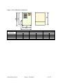
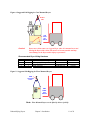
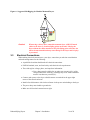
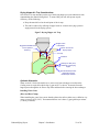
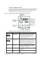
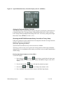
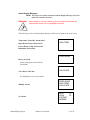
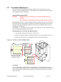
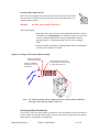
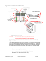
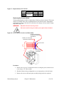
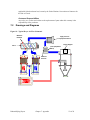
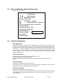
5-2
Preventative Maintenance
This section describes maintenance procedures which will increase the longevity and
efficiency of your dehumidifying dryer. Perform them at the regular intervals listed on the
dryer checklist on the previous page.
Servicing Process Air Filters
Caution!
Operating the dryer without the process air filter installed voids your
warranty!
Filter cleaning is an important part of your dryer maintenance program.
Dehumidifying dryers have a single cartridge canister-type filter in the process air loop. The
filter protects blowers from plastic fines drawn in from the drying hopper and prevents the
desiccant from being contaminated. Regular filter cleaning is essential to keep your dryer
operating at peak efficiency.
You can blow or vacuum the dirt out of the filter with compressed air, but remember, it could
become damaged from high-pressure blowing.
Recommendations for Cleaning and Replacing Filters
• Turn off and/or lock out electrical power to the dryer.
• Remove the threaded fastener securing the filter access cover, then remove the cover.
• Remove the nut on the center retaining rod to remove the filter cartridge.
Figure 14: Air Filter Location and Disassembly
Process Return
Air Filter
1" Wide x 1/8" Thick High
Temperature Gasket
Vacuuming
Try vacuum-cleaning a soiled filter first. Vacuuming removes most large particles and
surface contaminants, and may suffice for the first time you clean a filter. Use a commercialduty (recommended) or household vacuum cleaner. Vacuum the filter from the air intake
(dirty) side only.
Dehumidifying Dryers
Chapter 5: Maintenance
40 of 58
Cleaning with Compressed Air
Blow clean, dry compressed air up and down the pleats, blowing out the filter
from the inside out. Remove loose dirt from the filter with compressed air or
vaccum from the outside.
Caution!
DO NOT clean/wash filter with water!
After each cleaning:
• Inspect the filter element. Briefly hold a light bulb behind the element
and look for any fatigued paper or residual dirt. Inspect for holes and
tears by looking though the filter toward a bright light. Check for
damaged gaskets or dented metal parts. Do not re-use a damaged
filter!
• Check the gasket for damage. A damaged gasket allows contaminants
into the process. Replace as needed.
Figure 15: Cooling Coil Location and Disassembly
1" Wide x 1/8" Thick High
Temperature Gasket
Undo (4) 10-32 Button
Head Screws using 1/8
Allen Wrench
Note:
Use compressed air or a steam
cleaner to blow the dust off or clean
any oily residue on the coil.
To clean the cooling coil, use compressed air or a steam cleaner to blow the
dust off or clean any oily residue on the coil.
Servicing the Dew Point Monitor
The accuracy of the dew point monitor on mini dryer systems depends on proper operation of
the dew point sensor and the control board. The dew point sensor is in the process air stream
and is therefore susceptible to contamination.
Dehumidifying Dryers
Chapter 5: Maintenance
41 of 58
Dew point sensor life depends on:
• Air temperature and flow passing over the sensor.
• The amount of fines (dust) in the process air.
• The amount of plasticizer vapor in the process air.
Once every six months, the dryer operator should monitor the initial dew point sensor
readings and establish a periodic replacement schedule as needed.
Caution!
Do not attempt to check the continuity or resistance of the dew point
sensor.
The sensor will be destroyed!
5-3
Corrective Maintenance
This section provides you with the information necessary to correct or repair any issues
which might appear during the normal operation of your dehumidifying dryer. Although we
have listed how to perform these procedures, it is recommended that you call the Service
Department to have any in-depth maintenance performed.
Symptoms of Worn Desiccant
The moisture absorption capacity of the desiccant used in your dehumidifying dryer degrades
after an indefinite period of time. Useful life depends on variables such as material moisture
content, plasticizer vapors in the return air, and number of regeneration cycles.
Your dryer may need new desiccant if it exhibits any of the following symptoms:
• The process air dew point measured with a portable dew point monitor
is higher than -10°F (-23ºC) throughout the process drying cycle.
• Noticeable amounts of desiccant in the beds is a medium-brown color
or darker.
If you notice any of these signs, replace the desiccant in the desiccant beds. Desiccant
replacement kits are available from the Parts Department. If you want, a technician can
repack desiccant beds at your site.
Dehumidifying Dryers
Chapter 5: Maintenance
42 of 58
WARNING!
Handling desiccant material is HAZARDOUS.
Wear an N-100 type safety filter mask or equivalent to avoid prolonged
breathing of desiccant dust. Wear safety goggles and gloves to avoid
contact with eyes and skin.
• Handle with adequate ventilation.
• Wash hands thoroughly after handling.
: FIRST AID :
In case of eye contact, immediately flush eyes
with plenty of water for at least 15 minutes.
SEE A PHYSICIAN IMMEDIATELY IF IRRITATION PERSISTS.
Replacing Worn Desiccant
Caution!
DESICCANT BEDS ARE HOT DURING OPERATION.
To avoid burn hazard, make sure desiccant beds are sufficiently cool
before replacing worn desiccant.
To access the Desiccant Bed:
1. Disconnect electrical power to the dryer.
2. Using a 1/8” Allen wrench, remove the four (4) 10-32 button head screws holding the
Dessicant Cap to the Regeneration Heater.
3. Remove the Desiccant Cap.
4. With a shop vacuum, carefully remove all desiccant from each tower.
Dehumidifying Dryers
Chapter 5: Maintenance
43 of 58
Figure 16: Desiccant Bed Location and Disassembly
Undo (4) 10-32 Button
Head Screws using 1/8
Allen Wrench
Desiccant Cap
1" Wide x 1/8" Thick Silicon
Strip and Stick Gasket
13X Molecular Sieve
8x12 Beads
Regeneration Heater
Regeneration
Thermocouple
16 Mesh 0.028 Diameter Wire
Stainless Steel Screen
(2) 4-40 screws
Hi Temperature
Snap Switch
1" Wide x 1/8" Thick High
Temperature Gasket
For Spare Parts Lists, see page 55.
Caution!
You should properly dispose of any discarded desiccant.
Consult local disposal regulations for more information.
Inspect each lower desiccant screen for tears or holes where desiccant burned-through.
Replace as needed.
After cleaning each chamber, add a level layer of half the 8 x 12 bead desiccant on top of the
screen. Next, carefully add the full amount of bead desiccant specified per bed. Amounts are
listed in the Desiccant Amounts Table below. Smooth the top level, and finally add another
layer of the remaining bead desiccant to the top. Make sure this layer is level and smooth.
•
Repeat the previous step for the other bed.
•
Inspect the gaskets on the valve assembly. Replace if necessary.
•
Re-install the valve and reconnect actuator wiring.
Dehumidifying Dryers
Chapter 5: Maintenance
44 of 58
Figure 17: Required Desiccant Amounts
Dryer
model
15 cfm
30 cfm
60 cfm
8 x 12 bead Total
Part no.
lbs.
4.75
W00018051
12.25
27.5
Kg
2.15
5.56
12.5
Replacing the Process Heater
The dehumidifying dryers utilize a single-phase Calrod-type heater element. This heater
element is mounted in the center compartment below the desiccant beds. Although the
replacement procedure is the same for each heater, the wattage varies by model, voltage,
temperature range, etc.
WARNING!
Hazardous electrical current present.
Disconnect and lock out power before you replace heater elements!
Figure 18: Process Heater Location and Disassembly
Undo (6) 10-32 Button
Head Screws using 1/8
Allen Wrench
1" Wide x 1/8" Thick High
Temperature Gasket
(2) 4-40 screws
Hi Temperature
Snap Switch
Procedures
1. Remove the six (6) 10-32 button head screws securing the process heater access
cover using a 1/8” Allen wrench.
2. Sketch the heater wiring configuration so you can properly re-wire the heater.
3. Remove the wires to the heater plate assembly being removed or replaced.
Dehumidifying Dryers
Chapter 5: Maintenance
45 of 58
4. Remove the two (2) 4-40 screws securing the heater plate assembly, and slide out the
assembly.
5. Remove the heater from the mounting plate by removing the large brass nuts and
washers.
6. Re-install the heater and heater plate assemblies in reverse order. Install new heater
gaskets and securely tighten all fasteners.
Caution!
Heater loops should not touch each other.
“Hot spots” lead to premature heater failure!
7. Reinstall the wires based on the sketch you made earlier.
Dehumidifying Dryers
Chapter 5: Maintenance
46 of 58
Chapter 6: Troubleshooting
6-1
Introduction
The utmost in safety precautions should be observed at all times when working on or around
the machine and the electrical components. All normal trouble-shooting must be
accomplished with the power off, line fuses removed, and with the machine tagged as out of
service.
The use of good quality test equipment cannot be over-emphasized when troubleshooting is
indicated. Use a good ammeter that can measure at least twice the AC and DC current that
can be encountered for the machine. Be sure that the voltmeter has at least minimum
impedance of 5,000 OHMS-per-volt on AC and 20,000 OHMS-per-volt on DC scales.
Popular combination meters, VOM and VTVM can be selected to provide the necessary
functions.
Before making haphazard substitutions and repairs when defective electrical components are
malfunctioning, we recommend that you check the associated circuitry and assemblies for
other defective devices. It is common to replace the obviously damaged component without
actually locating the real cause of the trouble. Such hasty substitutions will only destroy the
new component. Refer to wiring diagrams and schematics.
Locating mechanical problems, should they occur, is relatively straightforward. When
necessary, refer to the parts catalog section.
Problem
Little or no air coming from
the process delivery tube.
Possible cause
Corrective action
Dirty filter.
Desiccant beds are contaminated
by material or plasticizer leaking
into the system.
Clean or replace filter.
Blower overload has tripped.
Blower fins filled with dust or
contaminants.
Suction in delivery tube,
pressure from the return tube.
Dehumidifying Dryers
Phase is reversed on power drop
coming into the dryer.
Chapter 6: Troubleshooting
Replace desiccant. See Page 43
for more information.
Fix the problem and reset the
overload.
Remove blower side plate,
clean baffles, replace.
Stop the dryer.
If the dryer was connected to
the drying hopper, check to see
if the desiccant and process air
heater has been contaminated
with resin.
If so, replace the desiccant and
remove any resin carry-over.
Otherwise, change the phase of
two legs of the three-phase
power drop.
47 of 58
Problem
Loss or reduction of process air
temperature.
Possible cause
Corrective action
Temperature control needs
adjustment.
Auto tune temperature control.
Process heaters are faulty.
Check for open heaters. Replace
if required.
Solid-state temperature
controller faulty.
Replace.
Process temperature was
adjusted in error by plant
personnel.
Process heaters are faulty.
Desiccant beds are
contaminated.
Material being dried differs
from material specified at the
time of purchase.
Loss or reduction in drying
capacity.
Break in flex hose to/from
drying hopper.
Airflow valve sticking or failing
to shift.
Blower fins filled with dust or
contaminants.
PLC Regeneration Bed LED
indicators both off.
Insufficient power to PLC
(Power LED is off).
Faulty PLC (PLC Power light is
on, Run light is off, and/or Error
light is on).
Regenerating bed cooldown.
Blower Input indicator is off.
Process air in high-temperature
condition.
PLC Regeneration Heater
Insufficient power to PLC
Left/Right output indicators both (Power light is off).
off.
Faulty PLC (PLC Power light is
on, Run light is off, and/or Error
light is on).
Faulty E5C2 temperature
control or regen over temp.
Dehumidifying Dryers
Chapter 6: Troubleshooting
Make sure that plant personnel
are aware of the proper
temperature set point. Post an
appropriate sign next to the
controller.
Replace.
Replace desiccant.
Drying systems are designed for
the material which was
originally specified. Different
materials may need a longer
residence time or a different
drying temperature.
Inspect for air leaks; replace as
needed.
Check for proper operation of
valve actuators. Repair or
replace if necessary.
Remove blower side plate,
clean baffles, replace.
Replace filter elements.
Check power wiring to PLC.
Replace PLC.
None.
Verify that blower contactor is
on. Check input wiring to PLC.
None.
Check power supply and power
wiring to PLC.
Replace PLC.
Make sure control is properly
inserted to base. Loose temp
control connection.
48 of 58
Problem
Material in drying hopper cakes,
or meltdown occurs.
Possible cause
Corrective action
Air restriction.
Valve out of position, smashed
hoses, blower problem.
Process temperature set too high
due to operator error.
Check resin manufacturer’s data
sheet for proper drying
temperature. Make sure plant
personnel are aware of the
correct process temperature set
point.
High temperature alarm not set
properly.
Process set point is out of
acceptable range.
Function set for degrees Celsius
(ºC), set point at degrees
Fahrenheit (ºF).
Process thermocouple not in
airflow.
Poor dew point performance.
Nothing displays when the
controller is turned on.
Burned out regeneration heater.
Contaminated or worn out
desiccant.
Leaking process air hoses.
Dryer operates beyond its
capacity.
Bad dew point sensor.
Fouled dew point sensor
manifold.
Dirty filter.
The internal mechanism is not
inserted properly into the
housing.
The power supply is not
connected to its terminals
properly.
No power is supplied, or the
supplied power is not within the
specified range.
Disconnect switch or Control
Power switch not set to ON.
Control Power fuse blown.
Reoccurring high regeneration
alarm.
Dehumidifying Dryers
Air flow problem. Control set
too high.
Chapter 6: Troubleshooting
Reset high temperature alarm.
Restore temperature controller
to factory pre-sets.
Verify correct Celsius or
Fahrenheit settings.
Verify that the thermocouple is
properly installed in the inlet
tube.
Repair or replace.
Replace.
Repair or replace.
Check dryer and drying hopper
sizing.
Replace.
Clear obstruction. Air should
flow freely through sensor.
Clean or replace filter element.
Properly insert the internal
mechanism into the housing.
Properly connect the power
supply to the power supply
terminals.
Supply a voltage of 85 to 125
VAC to the power supply
terminals of the controller.
Check control power fuse for
continuity. Turn disconnect
switch and control power switch
ON.
Check air flow. Lower E5C2.
49 of 58
Problem
Possible cause
Corrective action
No setting change possible on
temperature controller.
The key protection switch is set
to ON.
Input polarity on thermo-couple
is wrong or connection is wrong.
Set the key protection switch to
OFF.
Input-type setting is incorrect.
Properly set the input with the
input-type selector rotary
switch.
No compensating lead wires
used for extension of the
thermocouple.
Use proper compensating lead
wires and terminals.
Thermocouple and controller are
connected by wires other than
proper lead wires.
Process value is abnormal or
not obtained.
Process thermocouple not in
airflow.
Sensor is broken or shortcircuited.
The controller is influenced by
noise or other induction.
Celsius temperatures used
instead of Fahrenheit or vice
versa.
Process value shifted because
the input shift function is used.
6-2
Properly wire the terminals.
Use a dedicated thermocouple
connector. If a connector is a
metal different from the
thermocouple and controller, a
temperature error may result.
Verify that the thermocouple is
properly installed in the inlet
tube.
Replace with a good sensor.
Separate input wires as far as
possible from the origin of the
noise.
Check Mode selector switch 6:
• ON - ºF
• OFF - ºC
Set input shift value to 0, or set
mode selector switch 4 to OFF.
Determining Temperature Controller Errors or Sensor Errors
Using a Thermocouple
If the controller displays a temperature that is close to room temperature (70ºF/21ºC) when
you short-circuit controller input terminals, the controller is normal and the sensor is probably
broken, short-circuited, or incorrectly wired.
Using a Platinum Resistance Thermometer
If the controller displays a temperature of about 0.0°C (32ºF) when you insert a 100-ohm
resistor between terminals A and –B of the controller, and you short-circuit controller
terminals +B and –B, the controller is normal and the sensor is probably broken, shortcircuited, or incorrectly wired.
Other service problems or questions can be answered by contacting the Service
Department.
Dehumidifying Dryers
Chapter 6: Troubleshooting
50 of 58
Chapter 7: Appendix
7-1
Warranty
Unless otherwise specified, this product includes a Standard ONE YEAR PARTS
WARRANTY.
Warranty Specifications
The manufacturer hereby expressly warrants all equipment manufactured by it to be free from
defects in workmanship and material when used under recommended conditions, as set forth
in the operating manuals for such equipment. THE FOREGOING EXPRESS WARRANTY
IS EXCLUSIVE AND IN LIEU OF ALL OTHER WARRANTIES, GUARANTIEES,
AGREEMENTS, AND SIMILAR OBLIGATIONS OF THE COMPANY AND/OR
MANUFACTURER (UNLESS OTHERWISE SPECIFIED IN THE SPECIFIC PRICE
PAGE OR LIMITED BY THE MANUFACTURERS’ WARRANTY FOR PARTS). The
Company’s obligation is limited to repair or replace FOB the factory any parts that are
returned, prepaid, within one year of equipment shipment to the original purchaser, and
which in the Company’s opinion, are defective. Any replacement part assumes the unused
portion of this warranty.
Warranty Restrictions
This parts warranty does not cover any labor charges for replacement of parts, adjustment
repairs, or any other work. This warranty does not apply to any equipment which, in the
Company’s opinion, has been subjected to misuse, negligence, or operation in excess of
recommended limits, including freezing or which has been repaired or altered without the
Company’s express authorization. If the serial number has been defaced or removed from the
component, the warranty on that component is void. Defective parts become the property of
the warrantor and are to be returned immediately, without any further use or handling.
Warranty Liabilities
THE COMPANY EXPRESSLY DISCLAIMS ANY AND ALL LIABILITY FOR ANY
SPECIAL, CONSEQUENTIAL OR INCIDENTAL DAMAGES OR EXPENSES THAT
RESULT FROM THE USE OF THIS PRODUCT. Some states do not allow the exclusion or
limitation of special, consequential or incidental damages, so the above limitation may not
apply to you. The Company’s obligation for parts not furnished as components of its
manufactured equipment is limited to the warranty of the manufacturers of said parts. The
company neither assumes nor authorizes any other persons to assume for it any liability in
connection with the sale of its equipment not expressed in this warranty. No person, agent,
manufacturer, distributor, dealer, installer or company is authorized to change, modify or
extend the terms of this warranty in any manner whatsoever.
The time within which an action must be commenced to enforce any obligation of the
Company’s arising under this warranty, or under any statute or law of the United States or
any state thereof, is hereby limited to the duration of this warranty. Some states do not permit
this limitation, so the above may not apply to you. This warranty gives you specific legal
rights and you may also have other rights which vary from state to state. For transactions
involving the potential applicability of international law or that of a foreign country,
this warranty policy and the procedures hereunder shall be governed by
Dehumidifying Dryers
Chapter 7: Appendix
51 of 58
applicable federal and state law, but not by the United Nations Convention on Contracts for
the Sale of Goods.
Customer Responsibilities
Any sales, use, or other tax incident to the replacement of parts under this warranty is the
responsibility of the purchaser.
7-2
Drawings and Diagrams
Figure 19: Typical Dryer Air Flow Schematic
Moisture
Exhaust
High pressure
prepheral blower
Drying Hopper
Valve
Filter (Separates
Dust)
Ambient
Air Flow
Dehumidifying Dryers
Chapter 7: Appendix
52 of 58
Figure 20: Machine-Mount Dryer Dimensions
Mounting flange
C
E
E
Diameter hole:
F
PROCESS
TEMPERATURE
DEW POINT
OFF
ON
B
CONTROL POWER ALARM HORN
ON
OFF
ALARM
ALARM Silencer
Notes: Hopper mounting flanges on 0.75 and
and 1.5 cu. ft. (20 & 40 liter) hoppers
are supplied blank so the customer
can drill to match existing machine throat.
3.0 cu. ft. (80 liter) hoppers and larger
are not supplied with a cast flange
(as shown).
D
A
15, 30, 60 cfm machine-mount dimensions in inches/cm
15 cfm
30 cfm
0.7 ft.3/20 liters 1.5 ft.3/40 liters 1.5 ft.3/40 liters 3.0 ft.3/80 liters
Dimension in.
cm
in.
cm
in.
cm
in.
cm
A
41
104
43
109
43
109
46
117
B
36
91
37
94
37
94
44
112
C
30
76
30
76
30
76
30
76
D
35
89
35
89
35
89
35
89
E
4
10.2
4
10.2
4
10.2
7
17.8
F
1.5
3.8
1.5
3.8
1.5
3.8
2
5.1
Dehumidifying Dryers
Chapter 7: Appendix
60 cfm
4.0 ft.3/120 liters
in.
cm
56.75
144
50
127
34
86
45.75
116
7
17.8
2
5.1
6.0 ft.3/160 liters
in.
cm
56.75
144
62
158
34
86
45.75
116
7
17.8
2
5.1
53 of 58
Figure 21: Floor-Mount Dryer Dimensions
CONTROL POWER
ON
OFF
ALARM HORN
ALARM Silencer
C
B
D
ALARM
DEW POINT
OFF
ON
PROCESS
TEMPERATURE
A
E
Dimension
A
B
C
D
E
Dehumidifying Dryers
15, 30, 60 cfm floor-mount dimensions in inches/cm
15 cfm
30 cfm
in.
cm
in.
cm
20
51
20
51
32.5
83
32.5
83
30
76
30
76
30
76
30
76
23.75
60
23.75
60
Chapter 7: Appendix
60 cfm
in.
24
32.5
30
34
28
cm
61
83
76
86
71
54 of 58
7-3
Spare Parts List
60CFM
575V 60 HZ 3PH 60CFM
460V 3PH
60CFM
400V 50 HZ 3PH 60CFM
230V 3PH
60CFM
220V 50 HZ 3PH 60CFM
208V 3PH
575V 60 HZ 3PH 30CFM
30CFM
460V 3PH
400V 50 HZ 3PH 30CFM
30CFM
230V 3PH
220V 50 HZ 3PH 30CFM
30CFM
208V 3PH
575V 60 HZ 3PH 15CFM
15CFM
15CFM
3
3
3
3
3
3
3
3
3
3
3
3
3
3
3
3
3
3
3
3
3
3
3
3
3
3
3
3
3
3
3
3
3
3
3
3
3
3
3
3
3
3
3
3
3
3
3
3
3
3
3
3
2
2
2
2
2
1
1
1
Chapter 7: Appendix
2
1
1
1
1
1
1
1
1
1
1
1
1
1
1
4.75 Lbs.
135 Inches
3
2
2
1
1
2
2
2
2
1 (ALL)
1
2
2
2
2
3
2
2
LEVEL 1 ( Mechanical Components )
PART #
SIZE Description
W00015435
Dew Point Sensor Insert Cable
A0548556
Dew Point Sensor
A0566467
Valve switch
A0566531
Process Air Filter
W00018051
13X molecular Sieve Desiccant ( 8 X 12 Beads )
W00013983
High Temperature Gasket.
A0566676
High Temperature Snap Switch.
Dehumidifying Dryers
3
460V 3PH
LEVEL 1 ( Electrical Components )
PART #
SIZE Description
A0568932
2
Fuse for the Heater Elements
A0568933
2.5 Fuse for the Heater Elements
A0568934
3
Fuse for the Heater Elements
A0534039
3.5 Fuse for the Heater Elements
A0534040
4
Fuse for the Heater Elements
A0534041
5
Fuse for the Heater Elements
A0534042
6
Fuse for the Heater Elements
A0534043
7
Fuse for the Heater Elements
A0534044
8
Fuse for the Heater Elements
A0534046
10 Fuse for the Heater Elements
A0534047
12 Fuse for the Heater Elements
A0534048
15 Fuse for the Heater Elements
A0534049
20 Fuse for the Heater Elements
A0568936
25 Fuse for the Heater Elements
A0434051
30 Fuse for the Heater Elements
A0568909
1
Fuse for the Process Blower
A0568910
1.125 Fuse for the Process Blower
A0568911
1.25 Fuse for the Process Blower
A0534804
2
Fuse for the Process Blower
A0568917
2.5 Fuse for the Process Blower
A0550577
3
Fuse for the Process Blower
A0568919
3.2 Fuse for the Process Blower
A0568921
4.5 Fuse for the Process Blower
A0550593
5.6 Fuse for the Process Blower
A0538062
6
Fuse for the Process Blower
A0568922
6.25 Fuse for the Process Blower
A0568923
7
Fuse for the Process Blower
A0568926
10 Fuse for the Process Blower
A0538069
12 Fuse for the Process Blower
A0536892
1.25 Fuse for the transformer
A0536894
1.6 Fuse for the transformer
A0536895
1.8 Fuse for the transformer
A0538001
3.2 Fuse for the transformer
A0538002
3.5 Fuse for the transformer
A0568941
2.8 Fuse for the transformer
A0558078
0.3-1 Motor Overload
A0558079
1-2.9 Motor Overload
A0558082
1.6-5 Motor Overload
400V 50 HZ 3PH 15CFM
208V 3PH
15, 30, 60 CFM
230V 3PH
15CFM
MINI DRYER SPARE PARTS LIST AD15, AD30, AD60
220V 50 HZ 3PH 15CFM
Figure 22: Level 1 Spare Parts List (Electrical & Mechanical)
1
1
1
1
12.25 Lbs.
163 Inches
3
55 of 58
1
1
1
1
27.5 Lbs.
188 Inches
3
1
1
LEVEL 2 ( Mechanical Components )
PART #
SIZE
Description
A0548621
Ceramic Cap for the End of Heater Elements
A0566478
750 Watts Heater element 208/220 Volts
A0566479
750 Watts Heater element 230 Volts
A0566480
750 Watts Heater element 400 Volts
A0566481
750 Watts Heater element 460 Volts
A0566482
750 Watts Heater element 575 Volts
A0566483
1250 Watts Heater Element 208/220 Volts
A0566484
1250 Watts Heater Element 230 Volts
A0566485
1250 Watts Heater Element 400 Volts
A0566486
1250 Watts Heater Element 460 Volts
A0566487
1250 Watts Heater Element 575 Volts
A0566601
2500 Watts Heater Element 208/220 Volts
A0566602
2500 Watts Heater Element 230 Volts
A0566603
2500 Watts Heater Element 400 Volts
A0566604
2500 Watts Heater Element 460 Volts
A0566605
2500 Watts Heater Element 575 Volts
A0568139
Screen Cover for the Desiccant Tanks
A0568140
Screen Cover for the Desiccant Tanks
A0568141
Screen Cover for the Desiccant Tanks
A0566682
1/4" OD Teflon Tube.
A0566415
Washer / Gasket for the Heater Elements
2
1
1
1
1
1
1
1
4
5
0
0
0
0
0
7
0
0
0
0
0
2
2
2
2
2
5
5
2
4
60CFM
460V 3PH
4
5
2
4
5
4
2
5
2
4
5
0
0
0
0
0
2
575V 60 HZ 3PH 60CFM
60CFM
230V 3PH
1
1
1
1
1
1
1
400V 50 HZ 3PH 60CFM
60CFM
208V 3PH
220V 50 HZ 3PH 60CFM
30CFM
460V 3PH
575V 60 HZ 3PH 30CFM
30CFM
230V 3PH
1
1
1
1
1
1
1
2
2
400V 50 HZ 3PH 30CFM
30CFM
208V 3PH
220V 50 HZ 3PH 30CFM
575V 60 HZ 3PH 15CFM
15CFM
460V 3PH
15CFM
230V 3PH
LEVEL 2 ( Electrical Components )
PART #
SIZE Description
A0558000
Motor Starter
A0530042
Mercury Heater Contactor
A0567917
Process Air Temperature Controller
A0544089
Regeneration Air Temperature Controller
A0558065
*
Dew Point Monitor
A0548555
*
Dew Point Circuit Board
A0505417
Regeneration T'Couple Relay
400V 50 HZ 3PH 15CFM
208V 3PH
15, 30, 60 CFM
220V 50 HZ 3PH 15CFM
MINI DRYER SPARE PARTS LIST AD15, AD30, AD60
15CFM
Figure 23: Level 2 & 3 Spare Parts List (Electrical & Mechanical)
0
0
0
0
0
4
3
3
3
3
3
3
2
5 Feet
8
2
5 Feet
14
5 Feet
10
Dehumidifying Dryers
Chapter 7: Appendix
1
1
1
1
1
1
1
1
1
1
1
1
1
1
60CFM
1
1
575V 60 HZ 3PH 60CFM
60CFM
230V 3PH
60CFM
208V 3PH
220V 50 HZ 3PH 60CFM
30CFM
460V 3PH
575V 60 HZ 3PH 30CFM
30CFM
230V 3PH
400V 50 HZ 3PH 30CFM
30CFM
208V 3PH
220V 50 HZ 3PH 30CFM
575V 60 HZ 3PH 15CFM
15CFM
15CFM
1
1
1
1
460V 3PH
1
1
1
1
400V 50 HZ 3PH 60CFM
LEVEL 3 ( Mechanical Components )
PART #
SIZE
Description
A0534059
2" O.D. by 12 Ft Long Hi Temp Hose.
A0534060
2-1/2" O.D. by 12 Ft Long Hi Temp Hose.
A0566535
Return Air Cooling Coil
A0536628
208/460 Volt Process Blower.
A0536629
575 Volt Process Blower
A0534079
208/460 Volt Process Blower.
A0535351
575 Volt Process Blower
A0552439
208/460 Volt Process Blower.
A0552440
575 Volt Process Blower
460V 3PH
Description
Power Disconnect
Mitsubishi Programmable Relay Logic Controller
Redundant Temperature Safety Controller
230V 3PH
SIZE
400V 50 HZ 3PH 15CFM
PART #
A0567921
A0566096
A0568961
220V 50 HZ 3PH 15CFM
15, 30, 60 CFM
LEVEL 3 ( Electrical Components )
208V 3PH
15CFM
MINI DRYER SPARE PARTS LIST AD15, AD30, AD60
1
1
1
1
1
1
1
1
1
1
1
1
56 of 58
7-4
Returned Material Policy
Credit Returns
Prior to the return of any material authorization must be given by the manufacturer. A
RMA number will be assigned for the equipment to be returned.
Reason for requesting the return must be given.
ALL returned material purchased from the manufacturer returned is subject to 15% ($75.00
minimum) restocking charge.
ALL returns are to be shipped prepaid.
The invoice number and date or purchase order number and date must be supplied.
No credit will be issued for material that is not within the manufacturer’s warranty period
and/or in new and unused condition, suitable for resale.
Warranty Returns
Prior to the return of any material, authorization must be given by the manufacturer. A
RMA number will be assigned for the equipment to be returned.
Reason for requesting the return must be given.
All returns are to be shipped prepaid.
The invoice number and date or purchase order number and date must be supplied.
After inspecting the material, a replacement or credit will be given, at the manufacturer’s
discretion. If the item is found to be defective in materials or workmanship, and it was
manufactured by our company, purchased components are covered under their specific
warranty terms.
Dehumidifying Dryers
Chapter 7: Appendix
57 of 58
7-5
Dryer Identification (Serial Number) Tag
(Located on back of Dryer)
Company Logo
XXX Series Dryer
Model Number XXX-15
Max Drying Capacity HR
460V
Serial Number 060701R
1Ǿ
Date of Manufacture Month/Year
4.5A
Over-current Protection Device (s) 4.5A Total
Frequency 50/60Hz
Compressed air supply None
Dryer Mass 400 lbs/(180 KG)
Electrical Diagrams &
Pneumatic Diagram
Street Address
Telephone Number
7-6
City, State Zip Code
Technical Assistance
Parts Department
Call toll-free 7am–5pm CST [800] 423-3183 or call [630] 595-1060, Fax [847] 273-7700; (847) 273-7812
The ACS Customer Service Group will provide your company with genuine OEM quality parts
manufactured to engineering design specifications, which will maximize your equipment’s performance
and efficiency. To assist in expediting your phone or fax order, please have the model and serial
number of your unit when you contact us. A customer replacement parts list is included in this manual
for your convenience. ACS welcomes inquiries on all your parts needs and is dedicated to providing
excellent customer service.
Service Department
Call toll-free 8am–5pm CST [800] 423-3183 or call [847] 273-7700
Emergencies after 5pm CST, call [847] 439-5655
We have a qualified service department ready to help. Service contracts are available for most
products.
Sales Department
Call [847] 273-7700 Monday–Friday, 8am–5pm CST
Our products are sold by a world-wide network of independent sales representatives. Contact our Sales
Department for the name of the sales representative nearest you.
Contract Department
Call [847] 273-7700 Monday–Friday, 8am–5pm CST
Let us install your system. The Contract Department offers any or all of these services: project planning;
system packages including drawings; equipment, labor, and construction materials; and union or nonunion installations.
Dehumidifying Dryers
Chapter 7: Appendix
58 of 58