1
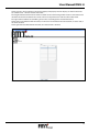
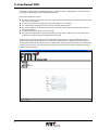
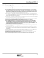
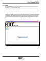
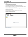
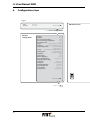
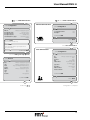
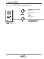
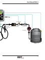
User Manual DMS DieselManagementSystem 1 ·/ 4 GHI 7 PQRS 2 ABC 5 JKL 8 TUV 3 DEF 6 MNO 9 WXYZ 0 G User Manual DMS Table of contents 1. 2. 3. 3.1. 3.2. 3.3. 3.4. 3.5. 3.6. 4. 4.1. 4.1.1. 4.1.2. 4.2. 4.3. 4.4. 4.5. 4.6. 4.7. 4.8. 4.9. 4.10. 4.11. 4.12. 4.13. 4.14. 5. 5.1. 5.2. 6. 7. 8. 2 Document history_____________________________________________________________________3 Synopsis_ ___________________________________________________________________________3 How to install DMS____________________________________________________________________4 Windows____________________________________________________________________________4 Linux_______________________________________________________________________________4 Uninstall DMS________________________________________________________________________4 Update DMS_________________________________________________________________________4 Backup data files______________________________________________________________________4 DMS on Mac_________________________________________________________________________5 How to use DMS______________________________________________________________________5 Starting DMS_________________________________________________________________________5 Windows____________________________________________________________________________5 Linux_______________________________________________________________________________5 Tabellen benutzen_ ___________________________________________________________________5 Main menu__________________________________________________________________________6 Log in / out__________________________________________________________________________7 User management_ ___________________________________________________________________8 Standard user________________________________________________________________________9 Supervisor___________________________________________________________________________9 Service user__________________________________________________________________________9 Vehicle Management_________________________________________________________________10 DMS Management___________________________________________________________________11 General configuration_ _______________________________________________________________15 Export_____________________________________________________________________________17 Import_____________________________________________________________________________18 View data_ _________________________________________________________________________19 How to modify DMS language files______________________________________________________21 Language files for PC application_ ______________________________________________________21 Language files for station hardware_ ____________________________________________________21 Configuration steps_ _________________________________________________________________22 Data-flow DMS Dieselmanagementsystem_______________________________________________24 General survey DMS DieselManagementSystem___________________________________________26 User Manual DMS G 1. Document history Date Name VersionChange 03/11/2008 NS 1.00 Initial draft 22/01/2009 NS 1.10 Adapted to DieselFixx Version 1.1 01/12/2009 NS 1.30 DieselFixx => DMS Version 1.4: Configuration and Data view extended. DMS on Mac Note acc. to usage of second tank 11/12/2009 NS 1.31 reset to factory settings 01/02/2010 NS 1.32 User editing restrictions 16/03/2010 HD 1.33 small revision 2. Synopsis This document describes the installation, use and modification options of the PC application of DMS. This application is used to configure the hardware, manage users, vehicles and stations, and view the data collected by the hardware. Throughout this document we will refer to the jar file and all other files used and managed on the PC as the “DMS PC application”. To all parts of the station hardware, including the iButton, the control unit, the firmware and anything else, we will refer to as the “DMS hardware”. This document consists of three major parts: ■■ ■■ ■■ The first part in chapter 3 describes the installation of the DMS PC application. The second part in chapter 3.6 describes the usage of the DMS PC application; especially what each display is used for and which options each type of user can use or not. The third part in chapter 5 describes how to modify the files used by DMS, if needed. The DMS PC application is designed to run under Windows and Linux as well. There are some differences at these operating systems, the application has to care about. This will be discussed in separate sub sections, one for Linux and one for Windows, wherever this affects the user. Please note: Names or commands in code document. style like this shall have to be typed-in exactly as they are written in this 3 G User Manual DMS 3. How to install DMS DThe DMS is already configurated with the Java Runtime Environment for Windows and Linux. Use these files if you cannot get actual JRE’s by updating your system over the internet. The following files can be found on the installation CD. ■■ ■■ jre-6u7-windows-i586-p-s.exe jre-6u7-linux-i586.bin contains Java for Windows contains Java for Linux The DMS installation files are also available separated for Windows and Linux: ■■ ■■ 3.1 DMSW32Setup.msi DMS.tar.gz contains DMS installation for Windows contains DMS installation for Linux Windows IFirst install the actual Java runtime environment. We deliver the JRE 6 with DMS. To install this, just execute jre-6u7-windows-i586-p-s.exe. The next step is to execute DMSW32Setup.msi which will install the DMS files. This copies the file DMS.jar and the folder DMSdata in the directory you have chosen during the installation process. It also creates a shortcut in the Windows “Startmenu”. If you want to use the iButton-Reader (since DMS version 1.3) you must install the drivers and setup the reader. Run the install file (e.g. install_1_wire_drivers_x86_v402.msi) provided with the reader and follow the instructions. After successful installation go to Start ➜ Programs ➜ 1-Wire Drivers x86 ➜ Default 1-Wire Net.exe. Click on the button “Auto-Detect” in the lower left corner (the reader must be connected to the PC) and confirm the found interface. You now can use the reader in DMS (see section 4.5). 3.2 Linux Please update your Linux system and install the sun-java6-jre or a similar one if available. If not, install Java by executing the jre-6u7-linux-i586.bin from the DMS installation. The DMS PC application will possibly not run correctly with other Java Runtime Environment then the Sun JRE. Copy the file DMS.tar.gz to the home directory of the user that shall use the DMS PC application. To unpack the tar archive type in tar -xzf DMS.tar.gz on the Linux shell. This will place the DMS.jar file in the home directory and creates the folder DMSdata in which all files used by DMS are stored.. 3.3 Uninstall DMS To uninstall DMS go to Windows Control panel and open the “Software” assistant. Then select DMS and click “Remove”. This will remove the DMS PC application files. The XML files with the data will remain on the disk. To uninstall DMS under Linux delete the DMS.jar and the DMSdata folder. All files will be lost then.. 3.4 Update DMS To update DMS under Linux do unpack the new DMS.tar.gz file similar to section 3.2. To update DMS under Windows first uninstall DMS similar to section 3.3 and then install DMS using the new *.msi file similar to section 3.1. 3.5 Backup data files All data used by DMS PC application is stored in the DMSdata folder. You should at least backup all *.xml files in this folder. If you restore files from backup copy all files back to the DMSdata folder. 4 User Manual DMS G 3.6 DMS on Mac To use DMS on Mac you need JavaSE 6 (32-bit or 64-bit). These must in the first row of the “Java Preferences” -> “Java Applications” (see screenshot). To install DMS, please copy the file DMS.tar.gz in a folder with write-access and unzip the archive there. This will create the file DMS.jar and the DMSdata folder. You can start DMS by typing java -jar DMS.jar on the console when in the installation folder. Usage of the iButton-Reader is not possible on the Mac. 4. How to use DMS 4.1 Starting DMS To start the DMS PC application run the DMS.jar. In the following we describe how this is done on the according operating system. 4.1.1. Windows If the Java Runtime Environment JRE 6 is installed properly you can start the DMS.jar by double clicking on it. If this does not work you can type %jre%\bin\javaw -jar %dms% \DMS.jar on the windows command prompt. Where %jre% is the path to your JRE installation and %dms% the path to your DMS installation. For example: C:\Programme\Java\jre1.6.0\bin\javaw -jar C:\DMS\DMS.jar DThe installation program of DMS will give you a batch file named DMS.bat, so you don’t have to open a command prompt and type in all the paths every time. Just double click on the batch file. 4.1.2. Linux On modern Linux distributions you have a default program to open each type of file. So when you have installed the sun-java6-jre you can start the DMS.jar by just right click on it and choose “Open with Sun Java 6 Runtime”. If this is not possible, you can just type in java -jar DMS.jar in the Linux shell. 4.2 Tabellen benutzen All tables in the DMS PC application can be handled in the same way. If you want to delete, change or adjust an user, vehicle, station or something else, first select the according line, then click the change or delete button. 5 G User Manual DMS Each table can be sorted by clicking on the header of the column you want to sort by. Click again to sort inverse. Columns can also be resized by dragging the border of the column header. 4.3 Main menu After starting the application you will see the main menu screen below. The most buttons are disabled for security reason. Before you can do anything you have to log in and verify yourself. (See section 4.4 “Log in / out”) After you are logged-in successfully you will see the main menu as shown below. Depending on your user type some buttons may still be disabled. (See section 4.5 “User management”) 6 User Manual DMS G 4.4 Log in / out On the “Log in” screen you can type your DMS user name and your DMS password. If the name or password are incorrect or do not match, you will get a message. If your name and password are correct you will automatically be led to the main menu. The buttons on main menu are active now, according to your user rights. The “Log in” button now has changed to a “Log out” button. Pressing this button will log you out and deaktivate all buttons except the “Log in” button. Please note: When the DMS PC application is started for the very first time there is only one default user with the user name Admin and the password Admin Please change this password immediately or create your own service user. The Admin user cannot be deleted. 7 G User Manual DMS 4.5 User management The “User management” screen gives you an overview of all users and their properties. You can create new users, change existing ones or delete them. User can be imported from SD-Card, see section 4.10 for details. Different user types have different permissions and restrictions. They are discussed in detail in the subsections below. On the “change” display (which is the same as the create user display) you can edit the properties of each user. ■■ ■■ ■■ ■■ ■■ ■■ ■■ ■■ ■■ Please note the following hints: The number can not be changed, it is managed internally. The password is not allowed to be empty. The PIN can be empty, otherwise it has to contain exactly four numerical digits. If at least one station is allocated, the PIN can not remain empty. The user “Admin” can not change his name and can not select refuelling stations. The iButton-Ident can be empty; otherwise it has to contain exactly 16 hexadecimal digits (letters can be set in upper case or lower case). This number must match the code of the iButton the user is utilising. The user type “Service” can only be set by service engineers users. To select or deselect stations and vehicles, just hold the CTRL key, while clicking the stations or vehicles you want to assign to the user. If you have the iButton-Reader connected to your PC and configured (see section 3), you can read-in the iButton-Ident directly from the iButton and assign to a user. Click on the button “Load iButton” and follow the instructions. 8 User Manual DMS G 4.6 Standard user The standard user is not able to change anything in the DMS PC application. He is allowed to view the data and configuration settings and to view users, stations and vehicles. He is also allowed to make draws on the stations assigned to him with the vehicles assigned to him. The need for a PIN or iButton for this operation is subject to prior set up in the configuration display (see section 4.8 “General configuration”). 4.7 Supervisor The supervisor user is allowed to do everything the standard user is allowed to do. ■■ ■■ ■■ ■■ ■■ ■■ ■■ 4.8 Additionally he is permitted to do the following additional actions: Import of the data from the stations (via SD card). Export of the the configurations and user setup to the stations (via SD card). Create, change and delete vehicles. Create, change and delete standard and supervisor users. Change service users, but not their user type. Create, change and delete stations and adjust their tank levels. Service user The service user rights have no limitation. He can do everything a supervisor can do and more: ■■ ■■ Create, change and delete service users. Change the general configuration. 9 G User Manual DMS 4.9 Vehicle Management The “Vehicle management” display provides an overview of all vehicles managed by DMS. Supervisor or service engineers users can create, change or delete vehicles. If you create a new vehicle you have to type in the car license number. This number can not be changed later! If you delete a vehicle, all user assignments of this vehicle to any users will be deleted automatically. 10 User Manual DMS G 4.10 DMS Management On the DMS management display you can create, change and delete stations and adjust the tank filling level. The columns “Filling level 1” and “Filling level 2” show the calculated level of the first and second tank. This value will change upon each adjustment, or when importing data for that station. The columns “Measured level 1” and “Measured level 2” show the level like it is measured by the DMS hardware. This is shown for information purposes. 11 G User Manual DMS On the “change” display you can provide a description or a location for each station and also describe each tank separately. The threshold value is used by the DMS hardware to decide when to issue a “tank empty” alert. It can be set from 0 up to 999999 litres. Using a second tank with this station If you like to use a second tank with this DMS - with a second sort of diesel - you can enter its name here. This name is also displayed on the terminal when the filling procedure starts. The fuelling user decides whether he uses the first or second diesel type/tank by lifting the correspondent diesel control nozzle. 12 User Manual DMS G Clicking on the “Tank 1” button in the change display will pop-up the tank display as shown below. You can edit the level - volume relation of the tank. The height should start from 0 in the first line down to the internal height of the tank in centimetres. This describes the distance between the sensor at the inner top of the tank and the surface of the fuel. The right column defines the tank filling level in litres according to the measured distance. Clicking the insert button below the table, a new row is inserted above the selected row, or at the end, if no row is selected. Clicking the delete button below the table, the selected row is deleted. 13 G User Manual DMS Clicking the adjust button on “DMS Management” display the “station adjust”display is shown. Here you can adjust on the filling level of each DMS stations’ tanks. Please note the following hints: ■■ ■■ ■■ ■■ ■■ ■■ The time and date are automatically set to current time and date, but you can change both to the time, the event is taking place. The user name cannot be changed, the currently logged-in user is shown. The amount of the adjustment is given in litres with two decimal places. The station number is set by the selection you have made on the “Station management” display. It is not changeable here. Please do not forget to choose the correct tank. The type of the adjustment is one of the following: charge, post or adjust. Draw is not possible here. Draws will be reported using the import from the SD card. A “charge” in this context means, you have discharged some fuel from a tank, the discharged volume will be automatically subtracted from the current level. A “post” means a refilling of the tank, the given amount will be added to the current level. An “adjust” means you just want to correct the level of the tank. In DMS you cannot set the level directly so you have to insert a positive or negative volume that will be added to the current level. 14 User Manual DMS G 4.11 General configuration The configuration display is only available for service engineers users, other users can view this screen, but cannot change anything. Please note the following hints: ■■ ■■ ■■ ■■ ■■ ■■ ■■ ■■ ■■ ■■ ■■ ■■ ■■ ■■ In the language list all available languages for DMS are shown. Available means, there have to exist two language files for a language to be listed: *_pc.txt and *_fw.txt (for example engl_pc.txt and engl_ fw.txt for English). Possible languages are English, French, German, Italian, Russian and Spanish. This selection does affect the language of the DMS PC application and the DMS hardware as well. (For file formats please refer to chapter 5 “How to modify DMS language files”) The character set setting gives you the choice between “Latin1” and “Cyrillic”. Set this to Cyrillic if you have text files with Cyrillic letters, like Russian texts, for the DMS hardware. The DMS PC application will display Cyrillic texts automatically correctly. If you choose “Yes” for “User shall give odometer reading”, then the user is forced to give the reading of his vehicles’ odometer before he can make a draw on a DMS. If you choose “Yes” for “User shall give operating hours”, then the user is forced to give the reading of his vehicles’ odometer before he can make a draw on a DMS. The maximum hand over on the DMS can be set from 0 (no maximum) up to 999 litres. The checkboxes in the sensors area activates the according sensor on the hardware. For the first tank you can fix a min. and max. value for the temperature and pressure sensor. These min. values are matched to the lower bound of the sensors metering range, the max. value to upper bound. The threshold gives the value, at which an alert will occur. The user identification on the DMS is possible by PIN, iButton or both of them. The vehicle selection can be made by typing in the car license number or selecting the vehicle from a list given on the display. The “Max PIN failure” is the amount of trials the user can make before the log-in blocks for a specific time. This time is set by the “Input lock after trials” field. The maximum is 10 trials and 30 minutes of blocking time. The delay between the last draw and the hardware going to standby can be set up to 1000 seconds. The display backlight will shut-off after the given time, which can be up to 30 minutes. The pump will start with a delay of up to 180 seconds after the nozzle is removed from the holder. The flow control time can be up to 120 seconds. The “Heater on”-temperature must be at least 3°Celsius below the “Heater off”-temperature. 15 G User Manual DMS Using the button “Factory settings” you can reset all settings to factory settings in case factory settings have been delivered. These files are “config.xml” and “language.xml” in the subfolder “DMSDefaultData”. If these files are not existing you cannot reset the settings. 16 User Manual DMS G 4.12 Export On the export display you can export the configuration, the text files, the font file, the user list and the tank description for the selected DMS station. Select a DMS station to export to in the first list, then select the drive or mount point of the SD card to write the data to, then click the export button. If the SD card is used for a station different to the selected one, you will be asked if you want to overwrite the data on the SD card. The drive list will contain all available drives if running under Windows, or all available mount points from the /media and /mnt directories if running under Linux. If your SD card is not listed here, just make sure it is mounted correctly by accessing them using the Windows explorer or your standard Linux explorer. Under Linux you can try remounting it to either /media or /mnt. If a file like the text file or font file is missing the export will stop and inform you. 17 G User Manual DMS 4.13 Import On the import display you can import the fuelling data from the DMS hardware via the SD card. Just select the drive or mount point from the list and click import. The drive list works exactly like the drive list on the export screen (section 4.9 “Export”). With the button “Import user” you can import users, that have been exported before. (When exporting a station, all users assigned to this station are exported, too). If the PIN of an imported user is the same as the PIN of an existing user, you will be asked to override the existing user or to skip the import of this user. After the import you are informed of the total number of imported (new and overwritten) users. During this import the station and all vehicles assigned to the users are imported too. Descriptions and passwords can not be imported.. 18 User Manual DMS G 4.14 View data On the “View data” display you can see all fuelling actions collected by the DMS hardware and the adjustments made in the station adjust display. You can filter the visible data by date. To do this, type the start and end of the time period you want to view in the fields above the table and then press the enter key. You can filter for name, approval number, station and tank number. Just select the value in the dropdown-list. The table is updated automatically. To reset the filter select “-“. All filters are also effective for print and CSV export. To print the table click the “Print” button. The printer setup dialog will be shown. Here you can choose the printer and make some more settings. The table will be scaled automatically so its width will fit on one page. If you click on the “CSV Export” button, then you can save the table as an CSV file (Excel import format). A file choose dialog will be shown where you can select where to store the file and the name of the file. These dialogs will be shown in the system language. Below the table the consumption (sum of the column “Amount”), the consumption per 100 km (average of all non-empty fields in column “Consumption l/100km”) and the consumption per hour (average of all non-empty fields in column “Consumption l/h”) are shown. 19 G User Manual DMS To reorganise the data, just click on the “Reorganisation” button. On the “Reorganisation” screen type in a period to delete. When you click the delete button all entries, between the given start and end time including the given start and end time will be deleted. 20 User Manual DMS G 5. How to modify DMS language files The language files used by DMS hardware and PC application must match specific format constraints. In the following sections we describe how to create or manipulate the files. 5.1 Language files for PC application The language files used by the DMS PC application are named with the language name in four letters and the postfix “_pc.txt” (for example enlg_pc.txt). In the file each line starts with a three-digit-number, like “001”, followed by a colon, and the translated text. For example: 008:Create 009:Delete 010:Log in 011:Log out Important: If changing a file do not change the line numbers! If you did so the text line is possibly not loaded into the PC application and the default text is used instead. Default texts are German. If saving the language file, make sure it is saved in the UTF-8 encoding. Most editors in Linux and Windows give you the encoding choice when using the “Save as” function. Using the UTF-8 encoding makes it possible to type Cyrillic letters as well as Latin letters and special letters like German “ä”, “ö”, “ü” or French letters with accents. Using a different encoding will cause some texts to be displayed wrong. 5.2 Language files for station hardware The language files used by the DMS hardware are named with the language name in four letters and the postfix “_fw.txt” (for example engl_fw.txt). The file begins with some comment lines, starting with a semicolon. Do not change them! All other lines consist of a line three-digit-number, a colon and the translated text. The translated text should not be longer than 20 letters. For example: 026:Setup 027:Date 028:Time 029:Calibration Important: If changing a file do not change the line numbers! If you did so the text line is possibly not loaded to the hardware and will be missing! If saving a language file, containing text in Latin letters (not Cyrillic letters), make sure it is saved with the encoding ISO-8859-1 or CP1252 (also known as “Windows western”), which are both nearly the same. If saving a language file containing text in Cyrillic letters, make sure it is saved with the encoding KOI8-R. Do not choose ISO-8859-5 or CP1251 (also known as “Windows cyrillic”), these are not supported by the DMS hardware. Most editors in Linux and Windows give you the encoding choice when using the “Save as” function. If using “Standard”, “ANSI” or “Platform” it is system dependent which encoding is used. Please use a high level text editor like OpenOffice.org Writer or Microsoft Word to get access to all encoding settings. 21 G User Manual DMS 6. Configuration steps Log-in Name Enter „Admin“ Password Enter „Admin“ DMS Administration Confirm with OK Select General configurations General configurations Language Select Symbol set Select The user must enter the mileage Select The user must enter the operating hours Max. discharge volume Pressure Select Max. 10 Activate with intergral sensor only Liquid level Activate with intergral level indicator only Integral leakage indicator Activate with intergral leakage indicator only Leakage Activate with intergral leakage indicator only Tank temperature Activate with intergral temperature indicator only Identification Select of vehicles Number of PIN failiures Time-out after PIN failiures Select Select Max. 10 Max. 30 minutes Waiting time between re-filling and idle-mode Heating on at Max. 1000 sec. Enter temperature Back-ground illumination Max. 30 min. Pump intermediate time Max. 180 sec. Flow-control time Heating shut-off at Max. 120 sec Enter temperature Confirm with OK Continue at 2 22 User Manual DMS G 2 3 select DMS Administration Select Vehicle administration Vehicle administration Select Configuration DMS. no. Select Configuration Will be pre-selected by the system Description/location Enter the location Description of tank 1 Enter the type of liquid Description of tank 2 Enter Desctiption Enter Confirm with OK If available only Level indication for „empty“ Car registration number Enter minimum level of liquid Select Back Click on Tank 1 (If level indicator abvailable only) Select Enter Select User adminstration (A line will be added. Enter height of liquid level and the equivalent litres.) User adminstration Confirm with OK Select line DMS (previously opened) Select Configuration No. Will be pre-selected by the system Name Select Revision Password PIN Date Will be pre-selected by the system Time Will be pre-selected by the system Name Volume DMS.no. Tank Type Remarks The person indicated will be announced. Enter re-filled volume Will be pre-selected by the system Select I Button-Ident Enter Enter Enter (4 digits) Enter manually or use the I Button reader Type of user Description Select Enter (optional) DMS-Correlation Select Vehicle correlation Select Select Enter (optional) Confirm with OK Continue at 3 Confirm with OK Select Back Configuration is completed. 23 G User Manual DMS 7. Data-flow DMS Dieselmanagementsystem Import to PC adminstration software SD d r Ca SD-card 1 ·/ 4 GHI 7 PQRS 2 ABC 5 JKL 8 TUV 3 DEF 0 6 MNO ➜➜DMS from SD-card ➜➜DMS no. … ➜➜Description of place ➜➜Tank / refilling station no. … ➜➜Date of refilling process ➜➜Time of refilling process ➜➜Name ➜➜Litres ➜➜Mileage ➜➜Vehicle license number ➜➜Operating hours 9 WXYZ SD d r Ca The configuration of the system will be transmitted with the SD-card to the DMS. DMS 1-n 24 User Manual DMS G Printer PC Data storage Reporting ➜➜Choice 1 specific time period ➜➜Choice 2 name of refuelling person ➜➜Choice 3 vehice license number ➜➜Choice 4 DMS 1 … n ➜➜Choice 5 tank / refilling station ➜➜Result indication 1 date ➜➜Result indication 2 time ➜➜Result indication 3 name ➜➜Result indication 4 vehicle license number ➜➜Result indication 5 volume discharged ➜➜Result indication 6 refilling station/tank ➜➜Result indication 7 mileage ➜➜Result indication 8 consumption / 100 km ➜➜Result indication 9 operating hours ➜➜Result indication 10 consumption l/h ➜➜Result indication 11 remarks ➜➜Result indication 12 description The configuration of the system will be generated on a PC and stored on the SD-card ➜➜Names of users ➜➜Configuration of i-button ident ➜➜Assignation of the i-button ident to a user ➜➜Number of permitted input failures (PIN) ➜➜Time-out after permitted input failiures (min) ➜➜Time between refuelling and non-operative time (sec) ➜➜Configuration of user pass-words ➜➜Type of user, user oriented ➜➜Classification of vehicles, user oriented ➜➜Decription of vehicles ➜➜Classification of refilling station = tank, user oriented ➜➜Decription of refilling station = tank ➜➜Minimum refilling level for empty tank 1 ➜➜Volume calibration = tank 1 ➜➜Volume adjustments ➜➜Language ➜➜Charakter set ➜➜Mileage input yes/no, user oriented ➜➜Input of operating hours yes/no user oriented ➜➜Max. refuelling voulme, all users ➜➜Pressure = refilling station 1: yes/no ➜➜Pressure = refilling station 1 = DMS 1: maximum pressure ➜➜Pressure = refilling station 1 = DMS 1: minimum pressure ➜➜Pressure = refilling station 1 = DMS 1: pressure threshold ➜➜Liquid level tank 1: yes/no = DMS 1 ➜➜Integral leakage sensor: yes/no = DMS 1 = tank 1 ➜➜Leakage: yes/no = DMS 1 = tank 1 ➜➜Pressure = refilling station 2 = DMS 1: pressure threshold ➜➜Tank empty = tank 2 = DMS 1 ➜➜Tank leakage = tank 2 = DMS 1 ➜➜Temperature of tank 1: yes/no = DMS 1 ➜➜Temperature of tank 1: min = DMS 1 ➜➜Temperature of tank 1: max = DMS 1 ➜➜Temperature of tank 1: threshold = DMS 1 ➜➜DMS heating switch-on at (°C) ➜➜DMS heating switch-off at (°C) ➜➜Background illumination (min) ➜➜Time delay of pump operation (sec) ➜➜Liquid-flow check time (sec) metered optional optional optional optional optional optional optional optional optional optional optional optional optional 25 G User Manual DMS 8. General survey DMS DieselManagementSystem 1 ·/ 4 GHI 7 PQRS 2 ABC 5 JKL 8 TUV 2.396.056 2.396.056 2.396.056 2.396.056 Pressure gauge 2.396.056 Disc valv In-line meter Diesel-filter, exchangeable Ultrasonic sensor for level indication Dieselpump Temperature sensor Leakage sensor Tank 1 26 Discharge valve storage holder User Manual DMS G 3 DEF 0 6 MNO 9 WXYZ DMS 1–n 2.396.056 Pressure gauge 2.396.056 2.396.056 2.396.056 2.396.056 charge ve Discharge Diesel-filter, exchangeable valve storage holder In-line meter Dieselpump Ultrasonic sensor for emptiness status Leakage sensor Tank 2 27 Service Manual DMS DieselManagementSystem 1 ·/ 4 GHI 7 PQRS 2 ABC 5 JKL 8 TUV 3 DEF 6 MNO 9 WXYZ 0 G Service Manual DMS Table of contents 1. 2. 3. 4. 5. 6. 7. 8. 8.1. 8.2. 8.3. 8.4. 9. 9.1. 9.2. 9.3. 9.4. 10. 10.1. 10.2. 10.3. 11. 12. 13. 14. 15. 15.1. 15.2. 16. 16.1. 16.2. 16.3. 16.4. 16.5. 16.6. 16.7. 16.8. 16.9. 17. 18. 19. 20. 21. 2 Document history_____________________________________________________________________3 Configuration________________________________________________________________________3 Identification________________________________________________________________________3 Vehicle selection______________________________________________________________________3 Mileage / diesel consumption control_____________________________________________________3 Operating Hours / gasoline consumption control_ __________________________________________3 Refuelling_ __________________________________________________________________________3 Supervisor___________________________________________________________________________4 Date________________________________________________________________________________4 Time_ ______________________________________________________________________________4 Calibration_ _________________________________________________________________________4 Calibration A_________________________________________________________________________4 Service______________________________________________________________________________4 FW Update_ _________________________________________________________________________4 Inputs_ _____________________________________________________________________________4 Outputs_____________________________________________________________________________4 Display Test__________________________________________________________________________4 SD-Card_____________________________________________________________________________5 Files on SD-Card______________________________________________________________________5 Data from PC application_______________________________________________________________5 Data to PC application_________________________________________________________________5 Timeouts____________________________________________________________________________5 Status LED / Error’s____________________________________________________________________6 Heater______________________________________________________________________________7 Battery______________________________________________________________________________7 Fuses_______________________________________________________________________________7 F1 / F2 Fuse power supply 230 V / 10 A____________________________________________________7 F3 Fuse power supply control unit_ ______________________________________________________7 Connectors__________________________________________________________________________7 Program download Connector, X4_ ______________________________________________________8 I-Button Connector, X6_________________________________________________________________8 Display Connector, X11_ _______________________________________________________________8 Display Backlight Connector, X10_ _______________________________________________________8 Keyboard Connector, X9_ ______________________________________________________________8 Power Connector, X1_ _________________________________________________________________9 Heater Connector 250 VAC, X3___________________________________________________________9 Pump Connector 250 VAC / 10 A, X2______________________________________________________9 I/O Connector, X13____________________________________________________________________9 Supervisor Menu____________________________________________________________ 10 Service Menu_ ______________________________________________________________________16 Operation of a refuelling process_ ______________________________________________________21 Data-flow DMS DieselManagementSystem_ ______________________________________________28 General survey DMS DieselManagementSystem___________________________________________30 Service Manual DMS G 1. Document history Date Name Version 28/10/2008 Ts 1.00 17/11/2008 Ts 1.01 09/12/2008 Ts 1.02 07/12/2009 HD 1.03 16/03/2010 HD 1.04 2. Change Initial draft Changes after new FW version Corrections new configuration elements for heater limits input of operating hours small revision Configuration The configuration will be updated every time the SD card is inserted to the control unit. 3. Identification The identification of the user will be executed with a PIN, the iButton or both. Determine by setup. The PIN is a 4 digit number. The iButton ID is a 16 digit hexadecimal number and is marked on the bottom of the key. Depending on the user type, the user has different rights of access. A “standard” user can fill his vehicle, the supervisor can set date and time and can calibrate the control unit. The service engineer can arrange hardware tests like a display test, verifying of the inputs and outputs and can update the system. The user type is will have be to configurated by the DMS PC application for every user. 4. Vehicle selection The vehicle selection can be effected either by a list of all assigned vehicles or with the manual input of the vehicle license number. If the selection is completed with the manual input of the license number, it will not be compared to the user’s vehicle assignment. 5. Mileage / diesel consumption control If the mileage is configured, the user has to enter the current mileage ahead of any refuelling process. With this input, the PC application is able to calculate an average diesel-consumption (per km) for the vehicle. 6. Operating Hours / gasoline consumption control If operating hours input is configured (alternatively or additionally to the mileage), the user has to enter the current reading of operating hours. With this input the PC application is able to calculate an average diesel-consumption (per operating hour) for the vehicle. 7. Refuelling After removing the diesel control nozzle, the pump will start with a certain delay set up in the PC application. This will prevent an overpressure, until the nozzle is placed in the vehicle tank. During the filling, the amount of diesel discharged is shown at the display. ■■ ■■ ■■ ■■ ■■ ■■ ■■ The pump stops automatically when meeting one of the following conditions: Tank level below minimum Leakage failure (Leakage detected or no communication to TankAlert sensor) The user is not identified Maximum amount for filling is reached (selectable on PC-Application) The flow control does not determine a definite diesel flow for the specified time. The nozzle is placed back. When the refuelling is completed and the nozzle is placed back correctly, all data are stored on the SD. 3 G Service Manual DMS 8. Supervisor 8.1 Date On this display the date can be set. Pushing the left and right arrow it is possible to switch between the day, the month and the year. To confirm the new date, press the RETURN button. 8.2 Time On this display the time can be set. Pushing the left and right arrow it is possible to switch between hours, minutes and seconds. To confirm the new time, press the RETURN button. 8.3 Calibration The selected refuelling tap connection can be calibrated on this display. Remove the diesel control nozzle and start filling a calibrated vessel. The amounts of flow rate counter pulses are shown on the display. After the vessel is filled, place back the control nozzle and enter the volume of the vessel. A pressing of the RETURN button will save the calibrated volume. If the control nozzle is not placed back correctly, and the RETURN button is pressed, the calibration will be aborted, also if no volume of the vessel is entered. 8.4 Calibration A The selected pump can be calibrated in this display with entering the pulse amount and the volume of the vessel. To switch between the input fields, use the up/down cursor. Pressing RETURN will save the calibrated volume. Volumes of zero are not allowed, they will abort the calibration. To copy a calibration from one control unit to another unit, copy the file “Calib.dat” from the SD-Card and place it on the SD-Card of the new control unit. 9. Service 9.1 FW Update This option is available, if a new firmware file exists on the SD card, only. To make a firmware update the firmware file “DMS.bin” must be placed in the DMSdata folder of the PC application. Start an “export” of the data to the SD card. The “DMS.bin” is copied to the SD card. Now insert the SD card and login as a “Service engineer” user at the control unit. The menu item firmware update is now available. Select the menu item by pressing the 1. To update the control unit, the RETURN key must be pressed in the updated display. The control unit makes a restart and loads the new firmware. After the restart, you should see the new version on the top right side. 9.2 Inputs This display shows all inputs of the control unit and their status, independent wether they are connected or not. If the input shows two columns, the first one shows the raw data read from the analogue input or the serial port. The second column shows the converted value. For the leakage of tank 1, the first value shows the input of the sensor connected to X13/9 (Digital Input), the second value is delivered from the TankAlert. With the “up” or “down” button switch to the next / previous page. 9.3 Outputs This display shows all outputs from the control unit and their status. With the “up” or “down” key, it is possible to mark an output. This output can be set with the “1” key or can be reset with the “0” key. 9.4 Display Test The display test will write the characters, fed in on the keyboard, to the display. It can be stopped by pressing RETURN. 4 Service Manual DMS G 10. SD-Card The SD-Card is the storage place of all data for the control unit. All refuelling process data and the filling level are written and stored there. The configuration, provided users and the text shown is read from it. So the SD-Card is designed to be used as the transport medium for the data between the control unit and the PC application. 10.1 Files on SD-Card The following files are on the SD-Card. Name Creator Text.txt PC application Config.dat PC application User.dat PC application DMS.bin PC application Tank1.dat PC application StationId.dat PC application Font.dat PC application Fuelling.dat Control unit Tank.dat Control unit Calib.dat Control unit Description Language text file Configuration file User file FW update file File for Tank Level calculation Control unit / station ID file Font file for control unit File with filling process data Fill level amount file Calibration value file 10.2 Data from PC application With the export function on the PC application, all necessary files are copied from the PC application to the SD-Card. The control unit detects the new SD-Card and reads all new files and reconfigures the unit. 10.3 Data to PC application With the import function on the PC application, all necessary file are copied from the SD-Card to the PC application. The file “Fuelling.dat” is deleted after it was read by the PC application. 11. Timeouts Name / Description Timeout Pin Input 1 min Vehicle selection 1 min I-Button connect after Pin Input 1 min Mileage input 1 min Display Tank name. Max. time to wait until control nozzle will have to be removed. 1 min Service acknowledgement time. Max. time until a service function is selected 1 min Supervisor acknowledgement time. Max time until a supervisor function is selected 1 min 5 G Service Manual DMS 12. Status LED / Error’s The Status LED is permanentely active, if the system runs trouble-free. In case of an error the LED will blink. Each error is shown with its own amount of blink states. After each error, there is a delay of 2 sec. 6 Blinks 1 2 Description SD Card missing Configuration file error Correction of the defects Insert SD card or remove and insert it again. The control unit cannot read the configuration file. Try to export data again from PC application. The language text file cannot be read. Try to export data again from PC application. The user tried to access to the control unit was unknown or the user file was missing. The process data file could not be written. SD not inserted or SD card is full. The control unit is not calibrated. The supervisor must calibrate the system. The font file cannot not be read. Try to export data again from PC application. The file with the level indication cannot not be read. Check if the level indication for the tank exists on the PC application and try to export data again from PC application. The file for the tank level cannot not be written. 3 Language text file error 4 User file error 5 Tank process file error 6 Calibration error 7 Font file error 8 Tank level table file error 9 Tank level file error 13 14 15 16 Tank 1 pressure / filter error Tank 1 minimum error Tank 1 leakage error Tank 1 temperature error 17 Tank 1 level sensor error 18 19 Tank 1 Temperature cable failure Tank 1 Pressure cable failure Check the filter. Check the tank level. Minimum is reached. The tank has a leakage. Suck out the liquid. The tank temperature exceeds the calibrated temperature. Check the reason for this error. Check the cable to the level sensor (Alert Sensor). Check the mounting of the sensor. Check the cable to the tank temperature sensor Check the cable to the pressure sensor 21 22 23 Tank 2 pressure / filter error Tank 2 minimum error Tank 2 leakage error Check the filter. Check the tank level. Minimum is reached. The tank has a leakage. Suck out the liquid. Service Manual DMS G 13. Heater The heater is optional. It is recommended, if the temperature can get very low. The display is specified for a temperature from -20°C to +70°C. If the temperature can get below this range, it is necessary to place the heater unit. The heater is switched on if the temperature falls below a configurable limit [°C] (Switch on Limit). If the inside temperature of the tank reaches a second limit, caused by the heating, the heater switcheds off again automatically (Switch off Limit). Both limits should be set appr. 10°C apart from each other to avoid a too frequent on-off switch of the heater. Possible pre-set data: Switch-on limit 0°C, switch-off limit +10°C If the heater unit is activated, it is self-controlling. 14. Battery The battery is placed to store the date / time on the control unit, if external power-supply is lost. The battery is designed for a lifetime of 5 years. 15. Fuses The control unit is secured by 3 fuses. 15.1 F1 / F2 Fuse power supply 230 V / 10 A The fuses F1 and F2 secure the power supply and should be designed for 230 V~ and 10 A. With these fuses the pumps are protected. 15.2 F3 Fuse power supply control unit The fuse F3 secures the power supply of the control unit and should be designed for 230 V~ and 1.5 A. 16. Connectors 14 15 16 17 18 19 20 21 22 23 24 25 26 1 2 3 4 5 6 7 8 9 10 11 12 13 1 2 3 4 1 2 3 7 G Service Manual DMS 16.1 Program download Connector, X4 Pin 1 2 3 4 5 Description 5 V output TxD RxD Reset Ground 16.2 I-Button Connector, X6 Pin 1 2 Description Signal Ground 16.3 Display Connector, X11 To adjust the contrast of the display, use the R24 potentiometer placed between the display connector X11 and the IO connector X13. Pin Description 1 FG 2 VSS 3 VCC 4 V adj 5 VEE 6 -WR 7 -RD 8 -CE 9 C/-D 10 -HALT 11 -RESET 12 D0 13 D1 14 D2 15 D3 16 D4 17 D5 18 D6 19 D7 20 NC 16.4 Display Backlight Connector, X10 Pin 1 2 Description 5V GND 16.5 Keyboard Connector, X9 Pin 1 2 3 4 5 6 7 8 Description Ret 0 Ret 1 Ret 2 Ret 3 Scan 0 Scan 1 Scan 2 Service Manual DMS G 8 Scan 3 16.6 Power Connector, X1 Pin 1 2 3 Description N PE L 16.7 Heater Connector 250 VAC, X3 Pin 1 2 Description L N 16.8 Pump Connector 250 VAC / 10 A, X2 Pin 1 2 3 4 Description L Pump 1 N Pump 1 L Pump 2 N Pump 2 16.9 I/O Connector, X13 Pin 1 2 3 4 5 6 7 8 9 10 11 12 13 Description Tank 1 control nozzle (Digital Input) Ground Tank 1 flow control (Digital Input) Ground Tank 1 pressure (Analog Input, 4 – 20 mA) Ground Tank 1 Tank temperature (Analog Input, 4 – 20 mA) Ground Tank 1 Leakage (Digital Input) Ground Tank 1 Level sensor (Serial Input) Ground 3,3 V / 5 V output supply Pin 14 15 16 17 18 19 20 21 22 23 24 25 26 Description Tank 2 gas nozzle (Digital Input) Ground Tank 2 flow control (Digital Input) Ground Tank 2 pressure threshold (Digital Input) Ground Tank 2 Tank Minimum (Digital Input) Ground Tank 2 Leakage (Digital Input) Ground Reserve Ground Reserve Contact Normal Close Don’t care, pulse Normal Open Blue Black Red Normal Close Done care, pulse Normal Open Normal Open Normal Open 9 G Service Manual DMS 17. Supervisor Menu Start of installation V 1. 7 02. 03. 10 PIN Input Ready V 1. 7 10: 49:06 02. 03. 10 Storeage depot PIN Input SD-card missing Calibration failure Failure 10 : 48 :36 Liquid level 1 ·/ 4 GHI 7 PQRS 2 ABC 5 JKL 8 TUV 3 DEF 0 6 MNO 9 WXYZ Insert SD-card into the DMS (PRESS any button for illumination.) 10 1 ·/ 4 GHI 7 PQRS 2 ABC 5 JKL 8 TUV 1000 3 DEF 0 6 MNO 9 WXYZ Request for PIN-input and calibration of the system (if not existing already) Service Manual DMS G V 1. 7 Ready PIN Input 1 ·/ 4 GHI 7 PQRS 2 ABC 5 JKL 8 TUV 3 DEF 0 6 MNO 9 WXYZ Enter 4-digits Supervisor PIN an press Return-button Ready V 1. 7 10: 49:06 02. 03. 10 Storeage depot Press iBbutton to DMS 1 ·/ 4 GHI 7 PQRS 2 ABC 5 JKL 8 TUV 3 DEF 0 6 MNO 9 WXYZ Request for i-button connection 11 G Service Manual DMS Ready V 1. 7 10 : 50:36 02. 03. 10 Storeage depot Calibrations 1 2 3 4 1 ·/ 4 GHI 7 PQRS 2 ABC 5 JKL 8 TUV 3 DEF 6 MNO 9 WXYZ Connect red Supervisor i-button 12 0 V 1. 7 Ready Date Time Calibration 1 Calibration 1 A 1 ·/ 4 GHI 7 PQRS 2 ABC 5 JKL 8 TUV 3 DEF 0 6 MNO 9 WXYZ The display shows any configurations to be done. Press buttons 1-4. Service Manual DMS G V 1. 7 Ready Date Time 09. 03. 2010 1 ·/ 4 GHI 7 PQRS V 1. 7 Ready 2 ABC 5 JKL 8 TUV 3 DEF 0 6 MNO 9 WXYZ Enter date using the number keys. Confirm with the Return-button. 10 : 04 : 10 1 ·/ 4 GHI 7 PQRS 2 ABC 5 JKL 8 TUV 3 DEF 0 6 MNO 9 WXYZ Enter time using the number keys. Confirm with the Return-button. 13 G Service Manual DMS V 1. 7 Ready Calibration 1 Pulsation Litres 1 ·/ 4 GHI 7 PQRS 2 ABC 5 JKL 8 TUV 50 1 3 DEF 0 6 MNO 9 WXYZ Calibration according to the demands 14 Ready V 1. 7 Calibration 1 Pulsation Litres - 1 ·/ 4 GHI 7 PQRS 2 ABC 5 JKL 8 TUV 3 DEF 0 6 MNO 9 WXYZ Confirm calibration ba a refilling process (see page 4, 8.4). Confirm with Return-button. Service Manual DMS G Ready V 1. 7 10 : 50:36 02. 03. 10 Storeage depot PIN Input 1 ·/ 4 GHI 7 PQRS 2 ABC 5 JKL 8 TUV 3 DEF 6 MNO 9 WXYZ 0 1 ·/ 4 GHI 7 PQRS 2 ABC 5 JKL 8 TUV 3 DEF 0 6 MNO 9 WXYZ Back at start menu 1 15 G Service Manual DMS 18. Service Menu (Check-up of the system and of the emergency functions) Ready V 1. 7 10 : 48 :36 02. 03. 10 Storeage depot PIN Input Ready 1 1 ·/ 4 GHI 7 PQRS 2 ABC 5 JKL 8 TUV Request for PIN-input 16 3 DEF 6 MNO 9 WXYZ 0 V 1. 7 PIN Input ·/ 4 GHI 7 PQRS 2 ABC 5 JKL 8 TUV 3 DEF 0 6 MNO 9 WXYZ Enter 4-digits Service PIN an press Return-button Service Manual DMS G Ready V 1. 7 10 : 49:06 02. 03. 10 Storeage depot Press iBbutton to DMS Ready V 1. 7 10: 50:36 02. 03. 10 Storeage depot 1 1 ·/ 4 GHI 7 PQRS 2 ABC 5 JKL 8 TUV 3 DEF 6 MNO 9 WXYZ Request for i-button connection 0 ·/ 4 GHI 7 PQRS 2 ABC 5 JKL 8 TUV 3 DEF 0 6 MNO 9 WXYZ Connect green Service i-button 17 G Service Manual DMS V 1. 7 Ready Hardwaretest Inputs Control valve 1 Liquid flow 1 Pressure 1 Liquid level 1 Leakage 1 Tank temp. 1 HW config. 2 Inputs 3 Outputs 4 Display test 1 ·/ 4 GHI 7 PQRS 2 ABC 5 JKL 8 TUV 3 DEF 0 6 MNO 9 WXYZ The display shows any configurations to be done. Press buttons 2-4. 18 V 1. 7 Ready 1 ·/ 4 GHI 7 PQRS 2 ABC 5 JKL 8 TUV 0 1 000 ---01 ---1 -000 --1 3 DEF 0 6 MNO 9 WXYZ Check inputs. Operating the different components 1 or 0 will appear. Service Manual DMS G V 1. 7 Ready Outputs Pump 1 0 Pump 2 0 Heating 0 Status LED 1 Backgr. Illum. 1 1 ·/ 4 GHI 7 PQRS 2 ABC 5 JKL 8 TUV 3 DEF Ready V 1. 7 10: 50:36 02. 03. 10 Display test Return to termination AAAAAAAA AAAAAAAA AAAAAAAA AAAAAAAA AAAAAAAA AAAAAAAx 0 6 MNO 9 WXYZ Check outputs. The selected component will go on line, i.e. the pump shall start operating, if you set 1. 1 ·/ 4 GHI 7 PQRS 2 ABC 5 JKL 8 TUV 3 DEF 0 6 MNO 9 WXYZ Check the complete display. Go back to starting menu pressing the Return-button. 19 G Service Manual DMS Emergency function to empty a leaking tank Ready V 1. 7 11: 05:24 02. 03. 10 Storeage depot PIN Input Failure V 1. 7 11: 05:24 02. 03. 10 Storeage depot PIN Input Tank Leakage 1 Liquid level 1 ·/ 4 GHI 7 PQRS 2 ABC 5 JKL 8 TUV Back at start menu 1 3 DEF 6 MNO 9 WXYZ 0 1 ·/ 4 GHI 7 PQRS 2 ABC 5 JKL 8 TUV 1000 3 DEF 0 6 MNO 9 WXYZ The display shows „Tank leakage“ (The complete tank installation is out of order.) This situation occurs if a tank leaks. Noticing the leak the pre-set leakage sensor blocks the complete installation. The leaking tank can be emptied by a manual switch on of the pump with the function“Check outputs“ in the Service menu. 20 Service Manual DMS G 19. Operation of a refuelling process Ready V 1. 7 10 : 48 :36 02. 03. 10 Storeage depot PIN Input 1 ·/ 4 GHI 7 PQRS 2 ABC 5 JKL 8 TUV Request for PIN-input 3 DEF 6 MNO 9 WXYZ 0 V 1. 7 Ready PIN Input 1 ·/ 4 GHI 7 PQRS 2 ABC 5 JKL 8 TUV 3 DEF 0 6 MNO 9 WXYZ Enter 4-digits User PIN an press Return-button 21 G Service Manual DMS Ready V 1. 7 10 : 49:06 02. 03. 10 Storeage depot Press iBbutton to DMS Ready V 1. 7 10: 50:36 02. 03. 10 Storeage depot 1 1 ·/ 4 GHI 7 PQRS 2 ABC 5 JKL 8 TUV 3 DEF 0 6 MNO 9 WXYZ Request for iButton connection (in case i-button is pre-defined) 22 ·/ 4 GHI 7 PQRS 2 ABC 5 JKL 8 TUV 3 DEF 6 MNO 9 WXYZ Connect black user iButton 0 Service Manual DMS G V 1. 7 Ready Choice of vehicle R-WW 11 R - R 76 1 ·/ 4 GHI 7 PQRS 2 ABC 5 JKL 8 TUV 3 DEF V 1. 7 Ready Mileage input 0 6 MNO 9 WXYZ Select vehicle identification number (if not pre-defined). 1 ·/ 4 GHI 7 PQRS 2 ABC 5 JKL 8 TUV 3 DEF 0 6 MNO 9 WXYZ Enter mileage (if the input of the mileage is requested) 23 G Service Manual DMS V 1. 7 Ready Operating hours input 1 ·/ 4 GHI 7 PQRS 2 ABC 5 JKL 8 TUV 3 DEF Tankvolume 1 Diesel 0 6 MNO 9 WXYZ Enter operating hours (if the input of the operating hours is requested) 24 V 1. 7 Ready 1 ·/ 4 GHI 7 PQRS 2 ABC 5 JKL 8 TUV Tank level is displayed. 3 DEF 6 MNO 9 WXYZ 0 Service Manual DMS G V 1. 7 Ready Ready 10: 49:06 Diesel V 1. 7 02. 03. 10 003.8 1 ·/ 4 GHI 7 PQRS Litres Litres 2 ABC 5 JKL 8 TUV 3 DEF 0 6 MNO 9 WXYZ The display waits for the start of refuelling. 1 ·/ 4 GHI 7 PQRS 2 ABC 5 JKL 8 TUV 3 DEF 0 6 MNO 9 WXYZ Refuelling in operation. 25 G Service Manual DMS V 1. 7 02. 03. 10 Ready 10 : 55:55 Diesel 016.2 Ready V 1. 7 11: 02:12 02. 03. 10 Storeage depot PIN Input Litres 1 ·/ 4 GHI 7 PQRS 2 ABC 5 JKL 8 TUV 3 DEF 0 6 MNO 9 WXYZ The total refuelled volume will be shown in litres after the refuelling process has been ended. 26 1 ·/ 4 GHI 7 PQRS 2 ABC 5 JKL 8 TUV 3 DEF 0 6 MNO 9 WXYZ The display automatically sets back to starting menu according to the pre-set time of the system. Service Manual DMS G 27 G Service Manual DMS 20. Data-flow DMS DieselManagementSystem Import to PC adminstration software SD d r Ca SD-card 1 ·/ 4 GHI 7 PQRS 2 ABC 5 JKL 8 TUV 3 DEF 0 ➜➜DMS from SD-card ➜➜DMS no. … ➜➜Description of place ➜➜Tank / refilling station no. … ➜➜Date of refilling process ➜➜Time of refilling process ➜➜Name ➜➜Litres ➜➜Mileage ➜➜Vehicle license number ➜➜Operating hours 6 MNO 9 WXYZ SD d r Ca The configuration of the system will be transmitted with the SD-card to the DMS. DMS 1-n 28 Service Manual DMS G Printer PC Data storage Reporting ➜➜Choice 1 specific time period ➜➜Choice 2 name of refuelling person ➜➜Choice 3 vehice license number ➜➜Choice 4 DMS 1 … n ➜➜Choice 5 tank / refilling station ➜➜Result indication 1 date ➜➜Result indication 2 time ➜➜Result indication 3 name ➜➜Result indication 4 vehicle license number ➜➜Result indication 5 volume discharged ➜➜Result indication 6 refilling station/tank ➜➜Result indication 7 mileage ➜➜Result indication 8 consumption / 100 km ➜➜Result indication 9 operating hours ➜➜Result indication 10 consumption l/h ➜➜Result indication 11 remarks ➜➜Result indication 12 description The configuration of the system will be generated on a PC and stored on the SD-card ➜➜Names of users ➜➜Configuration of i-button ident ➜➜Assignation of the i-button ident to a user ➜➜Number of permitted input failures (PIN) ➜➜Time-out after permitted input failiures (min) ➜➜Time between refuelling and non-operative time (sec) ➜➜Configuration of user pass-words ➜➜Type of user, user oriented ➜➜Classification of vehicles, user oriented ➜➜Decription of vehicles ➜➜Classification of refilling station = tank, user oriented ➜➜Decription of refilling station = tank ➜➜Minimum refilling level for empty tank 1 ➜➜Volume calibration = tank 1 ➜➜Volume adjustments ➜➜Language ➜➜Charakter set ➜➜Mileage input yes/no, user oriented ➜➜Input of operating hours yes/no user oriented ➜➜Max. refuelling voulme, all users ➜➜Pressure = refilling station 1: yes/no ➜➜Pressure = refilling station 1 = DMS 1: maximum pressure ➜➜Pressure = refilling station 1 = DMS 1: minimum pressure ➜➜Pressure = refilling station 1 = DMS 1: pressure threshold ➜➜Liquid level tank 1: yes/no = DMS 1 ➜➜Integral leakage sensor: yes/no = DMS 1 = tank 1 ➜➜Leakage: yes/no = DMS 1 = tank 1 ➜➜Pressure = refilling station 2 = DMS 1: pressure threshold ➜➜Tank empty = tank 2 = DMS 1 ➜➜Tank leakage = tank 2 = DMS 1 ➜➜Temperature of tank 1: yes/no = DMS 1 ➜➜Temperature of tank 1: min = DMS 1 ➜➜Temperature of tank 1: max = DMS 1 ➜➜Temperature of tank 1: threshold = DMS 1 ➜➜DMS heating switch-on at (°C) ➜➜DMS heating switch-off at (°C) ➜➜Background illumination (min) ➜➜Time delay of pump operation (sec) ➜➜Liquid-flow check time (sec) metered optional optional optional optional optional optional optional optional optional optional optional optional optional 29 G Service Manual DMS 21. General survey DMS DieselManagementSystem 1 ·/ 4 GHI 7 PQRS A J T 2.396.056 2.396.056 2.396.056 2.396.056 Pressure gauge 2.396.056 Dis valv In-line meter Diesel-filter, exchangeable Ultrasonic sensor for level indication Dieselpump Temperature sensor Leakage sensor Tank 1 30 Discharge valve storage holder Service Manual DMS G 2 ABC 5 JKL 8 TUV 3 DEF 0 6 MNO 9 WXYZ DMS 1–n 2.396.056 Pressure gauge 2.396.056 2.396.056 2.396.056 2.396.056 scharge ve Discharge Diesel-filter, exchangeable valve storage holder In-line meter Dieselpump Ultrasonic sensor for emptiness status Leakage sensor Tank 2 31