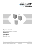
1
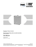
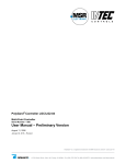
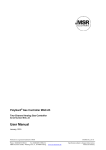
PolyGard Single Point Controller SPC3-11XX Single Point Gas Controller Serial Number _E_1007 User Manual May 2009 June 05, 2015 – Revision Polygard® is a registered trademark of MSR Customer Services (858) 578-7887 & (888) GO INTEC Fax (858) 578-4633 & (888) FX INTEC INTEC Controls, 12700 Stowe Dr., Suite 110, Poway, CA 92064 www.inteccontrols.com SPC3-11XX US Specification subject to change without notice. Printed in USA 150605 PolyGard® Single-Point Controller User Manual - SPC3-11XX Page 02 1 Description ...................................................................................................................................................... 4 2 Operating Instruction ..................................................................................................................................... 5 2.1 Description Keypad User Interface ........................................................................................................... 5 2.2 Setting / Changing Setups or Set points ................................................................................................... 5 2.3 Code Level ................................................................................................................................................ 6 3 Menu Overview ............................................................................................................................................... 6 3.1 Fault Management .................................................................................................................................... 7 3.1.1 Acknowledge a Fault.......................................................................................................................... 7 3.1.2 Error Memory ..................................................................................................................................... 7 3.1.3 System Errors .................................................................................................................................... 8 3.2 Stage Status .............................................................................................................................................. 8 3.3 Relay Status .............................................................................................................................................. 9 3.3.1 Manual Operation of the Relays ........................................................................................................ 9 3.4 Menu Sensor Reading ............................................................................................................................ 10 3.5 Menu Relay Setups ................................................................................................................................. 10 3.5.1 Relay Mode ...................................................................................................................................... 11 3.5.2 Relay Function Static / Flash ........................................................................................................... 11 3.5.3 Latching Mode ................................................................................................................................. 11 3.5.4 Horn Function .................................................................................................................................. 12 3.5.5 External Relay Operation ................................................................................................................. 13 3.5.6 Delay Mode of the Relay. ................................................................................................................ 13 3.6 Menu SP Setups ..................................................................................................................................... 13 3.6.1 Activate – Deactivate SP ................................................................................................................. 15 3.6.2 Selection Gas Type.......................................................................................................................... 15 3.6.3 Measuring Range............................................................................................................................. 16 3.6.4 SP Signal ......................................................................................................................................... 16 3.6.5 Stage/Set Point / Hysteresis ............................................................................................................ 16 3.6.6 Delay of Alarm ON or OFF .............................................................................................................. 16 3.6.7 Control Mode ................................................................................................................................... 17 3.6.8 SP Fault Assigned to Alarm ............................................................................................................. 17 3.6.9 Alarm Assigned to Alarm Relay ....................................................................................................... 17 3.6.10 SP Signal Assigned to Analog Output ............................................................................................. 17 3.7 Menu System Setups .............................................................................................................................. 18 3.7.1 Service Mode ................................................................................................................................... 19 3.7.2 Software Version.............................................................................................................................. 19 3.7.3 Maintenance Concept ...................................................................................................................... 19 3.7.4 Average Function ............................................................................................................................. 19 3.7.5 System Time, System Date ............................................................................................................. 20 3.7.6 Customer Password (Code 1) ......................................................................................................... 20 3.7.7 Analog Output .................................................................................................................................. 20 3.7.8 Define the Failure Relay .................................................................................................................. 20 3.7.9 Power On Time ................................................................................................................................ 21 4 Mounting / Electrical Connection ............................................................................................................... 22 4.1 Electrical Connection .............................................................................................................................. 22 4.2 Connection Diagram ............................................................................................................................... 23 4.3 Connector Block / Overview SPC3 Module ............................................................................................ 24 Polygard® is a registered trademark of MSR Customer Services (858) 578-7887 & (888) GO INTEC Fax (858) 578-4633 & (888) FX INTEC INTEC Controls, 12700 Stowe Dr., Suite 110, Poway, CA 92064 www.inteccontrols.com SPC3-11XX US Specification subject to change without notice. Printed in USA 150605 PolyGard® Single-Point Controller User Manual - SPC3-11XX Page 03 5 Commissioning............................................................................................................................................. 24 5.1 Commissioning ........................................................................................................................................ 24 5.2 Checklist Commissioning ........................................................................................................................ 25 6 Configuration and Setup Card .................................................................................................................... 26 6.1 Configuration Card of System Setups..................................................................................................... 26 6.2 Configuration Card of Alarm Relays ....................................................................................................... 26 6.3 Configuration Card of Measuring Setups ................................................................................................ 26 7 Specifications SPC3 ..................................................................................................................................... 27 8 Gas Sensor.................................................................................................................................................... 29 8.1 Description .............................................................................................................................................. 29 8.2 Calibration ............................................................................................................................................... 29 8.3 Zero-Point Calibration ............................................................................................................................. 29 8.4 Gain Calibration ...................................................................................................................................... 30 8.5 Exchange of Sensor Element ................................................................................................................. 30 8.6 Specification Gas Sensor ........................................................................................................................ 31 9 Notes and General Information ................................................................................................................... 32 9.1 Intended Product Application .................................................................................................................. 32 9.2 Installers` Responsibilities....................................................................................................................... 32 9.3 Maintenance ............................................................................................................................................ 32 9.4 Limited Warranty ..................................................................................................................................... 32 Polygard® is a registered trademark of MSR Customer Services (858) 578-7887 & (888) GO INTEC Fax (858) 578-4633 & (888) FX INTEC INTEC Controls, 12700 Stowe Dr., Suite 110, Poway, CA 92064 www.inteccontrols.com SPC3-11XX US Specification subject to change without notice. Printed in USA 150605 PolyGard® Single-Point Controller User Manual - SPC3-11XX Page 04 Single Point Gas Controller SPC3-11XX 1 Description The PolyGard® SPC3 Gas Controller is used for measuring, monitoring and warning of toxic gases. The toxic sensor (SP01) is mounted inside. One external gas transmitter (SP02) for toxic, combustible or refrigerant gases can be controlled additionally. Four alarm Stage/Set Points are free adjustable for each Sensor point(SP). Every alarm Stage/Set Point can be assigned to one of the maximum 4 alarm outputs (RX). The Gas Controller can interface via the (0)4 to 20 mA or (0)2 to 10 V output signal with any compatible electronic analog control, DDC/PLC control or automation system. The free adjustable setups and alarm Stage/Set Point make a very flexible use in the gas measuring possible. Simple and comfortable commissioning is possible due to factory-adjusted setups. The configuration setup settings and operation is easy to do without programming knowledge. The PolyGard® Single Point Gas Controller SPC3 must not be used in potentially explosive atmospheres. The SPC3 may only be used within ambient conditions described in the Technical Data. Polygard® is a registered trademark of MSR Customer Services (858) 578-7887 & (888) GO INTEC Fax (858) 578-4633 & (888) FX INTEC INTEC Controls, 12700 Stowe Dr., Suite 110, Poway, CA 92064 www.inteccontrols.com SPC3-11XX US Specification subject to change without notice. Printed in USA 150605 PolyGard® Single-Point Controller User Manual - SPC3-11XX 2 Page 05 Operating Instruction The complete configuration, parameterization and service are made via keypad user interface in combination with the display screen. Security is provided via two password levels. Alarm 1 Alarm 2 INTEC SPC3 2.1 Description Keypad User Interface Exit programming mode and saves settings; return to previous level or menu Enter Main Menus; scrolls through Main Menus and Sub Menus; increase or decrease a value Navigates through menus on the same level; moves cursor when inputing data Enter Sub Menus; accepts and stores data; silence horn (if assigned) LED orange: Flashes when alarm one or more alarms are active. Permanently on, when one of the relays is manually operated. LED red: Flashes when alarm two or more alarms are active. Permanently on, when one of the relays is manually operated. LED yellow: Flashes at system or sensor failure or when maintenance needed. LED green: Power LED 2.2 Setting / Changing Setups or Set points Open desired menu window. Code window opens, if no code level approved. After inputting the valid code the cursor jumps on the first position segment to be changed. Push the cursor onto the position segment, which is to be changed. Change the setup / set point. Save the changed value. Finish. Polygard® is a registered trademark of MSR Customer Services (858) 578-7887 & (888) GO INTEC Fax (858) 578-4633 & (888) FX INTEC INTEC Controls, 12700 Stowe Dr., Suite 110, Poway, CA 92064 www.inteccontrols.com SPC3-11XX US Specification subject to change without notice. Printed in USA 150605 PolyGard® Single-Point Controller User Manual - SPC3-11XX 2.3 Page 06 Code Level Code Level 1 Default Password = (1234) / Code Level 2 Password = (9001) All changes of setups and set point values are protected by a four-digit numeric code (= password). The code level 1 permits the operation of the SPC3; this code level is intended for the customer. The code can be changed individually via code level 2; see section 3.7.6. In code level 2 all setups and set points are released; this code level is only for the service technician. Code level 2 cannot be changed or deleted. The release of the code level is deleted if no button is pushed within 15 minutes. All menu windows are visible without entering a code. 3 Menu Overview The operation of the Single Point Gas Controller SPC3 is effected by a simple and logical menu structure that is easy to learn. The operating menu contains the following levels: x x x Starting menu. Main menu Submenu 1 and 2 Starting menu Main menu Submenu INTEC SPC3 System Errors Stage Status Relay Status Sensor Reading Relay Setup SP Setup System Setup Display and reset of errors See from point 3.1 Displays the status of actual alarms See point 3.2 Display of the relay status Manual operation of the relays Reset function of the relays See from point 3.3 Displays the Sensor Reading See point 3.4 Display and change of the relay setups See from point 3.5 Display and change of the sensor point setups Activate or Deactivate SP Assignment of the alarms to the alarm relay See from point 3.6 Display and change of the system setups See from point 3.7 Polygard® is a registered trademark of MSR Customer Services (858) 578-7887 & (888) GO INTEC Fax (858) 578-4633 & (888) FX INTEC INTEC Controls, 12700 Stowe Dr., Suite 110, Poway, CA 92064 www.inteccontrols.com SPC3-11XX US Specification subject to change without notice. Printed in USA 150605 PolyGard® Single-Point Controller User Manual - SPC3-11XX 3.1 Page 07 Fault Management The integrated fault management records the last 15 faults with date and time stamps in the menu “System Errors.” Additionally a record of the faults occurs in the “Error Memory”, which can be selected and reset only by the service technician. An actual fault is displayed in plain text in the starting menu. The failure relay, which is defined in the system setup “Failure relay”, is activated. The yellow LED in the front of the gas controller flashes. In case of fault of a sensor point (SP) the alarms defined in the menu “SP Setup” is activated additionally. 3.1.1 Acknowledge a Fault Attention: Acknowledging a fault is only possible after having removed the cause. System Errors Select menu “System Errors” SP 02 < 3mA 05.02 10.38 Example: Failure SP 01 < 3 mA SP 02 < 3mA Reset ?? Reset the fault? Fault reset SP 02 < 3mA Erased Fault reset 3.1.2 Error still exists Cause not eliminated Reset not possible Error Memory The menu “Error Memory“ in the main menu “System Error” can only be opened via code level 2. In the error memory the last 15 faults are listed for the service technician even if they were already acknowledged in the menu “System Error“. The deletion of each individual message is effected in the same way as the reset of a fault. Polygard® is a registered trademark of MSR Customer Services (858) 578-7887 & (888) GO INTEC Fax (858) 578-4633 & (888) FX INTEC INTEC Controls, 12700 Stowe Dr., Suite 110, Poway, CA 92064 www.inteccontrols.com SPC3-11XX US Specification subject to change without notice. Printed in USA 150605 PolyGard® Single-Point Controller User Manual - SPC3-11XX 3.1.3 Page 08 System Errors The following system error messages are recorded: SP 02 > 22 mA Cause: Short-circuit at analog input or transmitter not calibrated, transmitter defective. Solution: Check cable to transmitter, make calibration, and replace the transmitter. SP 02 < 3 mA Current signal to analog input < 3 mA / 1,3 VDC. (External Transmitter) Cause: Wire breaking at analog input or transmitter not calibrated, transmitter defective. Solution: Check cable to transmitter, make calibration, replace the transmitter. GC Error: 3.2 Current signal at analog input > 22 mA / 11 VDC. (External Transmitter) Internal communication error I/O Board to LCD Board. Cause: Internal error. Solution: Change the Gas Controller module. Maintenance: System maintenance is necessary. Cause: Maintenance date exceeded. Solution: Make the maintenance. Stage Status Display of the actual alarms in plain text in the order of their arrival. Only those measuring points are displayed, where at least one alarm is active. Changes are not possible in this menu. SP 01 A1 A2 Symbol SP 01 AX Description Measuring (SP) Point No. Stage Status Function A1 = A2 = A3 = A4 = Alarm 1 Alarm 2 Alarm 3 Alarm 4 ON ON ON ON Polygard® is a registered trademark of MSR Customer Services (858) 578-7887 & (888) GO INTEC Fax (858) 578-4633 & (888) FX INTEC INTEC Controls, 12700 Stowe Dr., Suite 110, Poway, CA 92064 www.inteccontrols.com SPC3-11XX US Specification subject to change without notice. Printed in USA 150605 PolyGard® Single-Point Controller User Manual - SPC3-11XX 3.3 Page 09 Relay Status The SPC3 has two alarm relays (R01 / R02) and two open collector outputs (R03 / R04). In the following description they are referred to as alarm relays. Display of the actual status of alarm relays. Manual operation of the alarm relays. R 01 OFF 3.3.1 Symbol Description R 01 Relay No. 01 OFF Relay Status Setting Status OFF Function Select Relay No. OFF = Relay OFF (No gas alarm) ON = Relay ON (Gas alarm) Manual OFF = Relay manual OFF Manual ON = Relay manual ON Manual Operation of the Relays The manual operation of the alarm relays is managed in the menu “Relay Status”. If a relay is in the manual ON or OFF status, the orange/ red alarm LED at the Gas Controller is lit continuously. The external operation of the alarm relay via an assigned digital input has priority to the manual operation in the menu "Relay Status" and to gas alarm. Relays manually operated in the menu “Relay Status” are deleted again by selecting the function "Automatic." Acknowledging the relays in latching mode is also effected in this menu. R 01 OFF Manual ON Manual OFF Manual OFF Select the relay Select the function of manual operation Select the function Manual ON Manual OFF Automatic Reset? = Relay ON = Relay OFF = Delete manual operation. = Reset of a latching mode. Take over the function Polygard® is a registered trademark of MSR Customer Services (858) 578-7887 & (888) GO INTEC Fax (858) 578-4633 & (888) FX INTEC INTEC Controls, 12700 Stowe Dr., Suite 110, Poway, CA 92064 www.inteccontrols.com SPC3-11XX US Specification subject to change without notice. Printed in USA 150605 PolyGard® Single-Point Controller User Manual - SPC3-11XX 3.4 Page 10 Menu Sensor Reading In this menu the current value (CV) with gas unit and gas type for each active sensor point (SP) is displayed. At control mode average value (AV) is the average value additional displayed. SP 01 CO ppm 50 *AV 33 CV 3.5 Setting Status Symbol Description SP 01 CO ppm CV AV * Not active Error Measuring P. No. Gas type CO Gas unit Current value CV Average value Control mode Status SP Not active Fault SP Function Selection of SP No See 3.6.2 See 3.6.2 Current value of gas concentration Average value (10 measured values within the time unit) Display of selected control mode (CV or AV) SP not active Current signal < 3 mA or > 22 mA Menu Relay Setups Display and change of the setups for each alarm relay Relay Setup (Main menu) R 01 (Select relay No.) Relay Mode De- energized Static / Flash 0s Latching Mode No Time 0s Quiet. DI 0 0 External Mode DI: ON = 0: OFF = 0 Delay ON Time 0s Delay OFF Time 0s Relay mode See 3.5.1 Relay function See 3.5.2 Activate latching mode See 3.5.3 Definition of horn function See 3.5.4 Definition of external relay operation See 3.5.5 Set delay time ON See 3.5.6 Set delay time OFF See 3.5.6 Polygard® is a registered trademark of MSR Customer Services (858) 578-7887 & (888) GO INTEC Fax (858) 578-4633 & (888) FX INTEC INTEC Controls, 12700 Stowe Dr., Suite 110, Poway, CA 92064 www.inteccontrols.com SPC3-11XX US Specification subject to change without notice. Printed in USA 150605 PolyGard® Single-Point Controller User Manual - SPC3-11XX 3.5.1 Page 11 Relay Mode Definition of relay mode: Symbol Description R 01 Relay No. Function Selection of relay DeRelay Mode energized 3.5.2 Setting Status energized De-energized Energized = Alarm ON = Relay ON = Alarm ON = Relay OFF Relay Function Static / Flash Definition of relay function 3.5.3 Symbol Description R 01 Relay No. 0 Function Setting Status Function Selection of relay 0 0 = Relay function static > 0 = Relay function flashing (= Time period in sec.) Impulse / Break = 1:1 Setting Status Function Latching Mode Definition of latching function Symbol Description R 01 Relay No. Selection of relay No Latching Mode No No Yes = Latching mode non active = Latching mode active Acknowledging a latching relay in the menu “Relay Status“ is only possible if the gas concentration is again lower than the alarm Stage/Set Point including hysteresis. In this case the status latching occurs in the display. Example: Alarm relay R2 with latching mode Alarm 2 On Display in the Menu Status Relay Relay 2 Reset in the Menu Status Relay Gas concentration higher Off R2 Off R2 On R2 On R2 On lower than threshold R2 Latching R2 Off On Off On Off Polygard® is a registered trademark of MSR Customer Services (858) 578-7887 & (888) GO INTEC Fax (858) 578-4633 & (888) FX INTEC INTEC Controls, 12700 Stowe Dr., Suite 110, Poway, CA 92064 www.inteccontrols.com SPC3-11XX US Specification subject to change without notice. Printed in USA 150605 PolyGard® Single-Point Controller User Manual - SPC3-11XX 3.5.4 Page 12 Horn Function The internal horn is connected to alarm relay R3 (open collector). This alarm output is defined as horn relay by this setup with the following possibilities to reset. x x x By pressing any of the 4 push-buttons (only possible in the starting menu). Automatic reset at the end of the fixed time. By an external push-button (assignment of the appropriate digital input). The horn function is only activated if at least one of the two setups (time or digital input) is set. Special function Response After acknowledging the output (by push-button or externally) time starts. When this time has run out and the alarm is still acting, the relay is set again. Symbol Description R 03 Relay No. Quit Mode Setting Status Function Selection of relay 0 0 = Reset of the relay after time having run out, or by push-button 1 = Reset of the relay by push-button, after time having run out and when alarm is still acting, relay is set again. (Response function). Time 120 Time for automatic reset function or response function 0 = no reset function DI 0 Assignment, which digital input resets the output. Acknowledge the horn output Alarm 3 On Of Relay 3 Gas concentration higher lower than threshold Time On Off Acknowledging signal On Off Special function “Response“. (Return of the horn relay) Alarm 3 On Gas concentration higher Off Time Relay 3 lower than threshold Time On Off Acknowledgingsignal On Off Polygard® is a registered trademark of MSR Customer Services (858) 578-7887 & (888) GO INTEC Fax (858) 578-4633 & (888) FX INTEC INTEC Controls, 12700 Stowe Dr., Suite 110, Poway, CA 92064 www.inteccontrols.com SPC3-11XX US Specification subject to change without notice. Printed in USA 150605 PolyGard® Single-Point Controller User Manual - SPC3-11XX 3.5.5 Page 13 External Relay Operation Assignment to a digital input (DI) for external switching of the alarm relay (ON and/or OFF). This function has priority to gas alarm and/or manual switching in the menu “Relay Status“. 3.5.6 Setting Status Function Relay No. External On 0 If digital input closed, relay switches ON External Off 0 If digital input closed, relay switches OFF Symbol Description R 01 DI-ON DI-OFF Relay Selection Delay Mode of the Relay. Delay time ON starts when the alarm is released and/or delay time OFF starts when the alarm returns to normal condition. 3.6 Setting Status Symbol Description R 01 Relay No. 0s Delay Time ON 0s Delay Time OFF 0 Function Relay Selection Mode ON: Relay is only activated at the end of the defined time (sec.) 0 sec. = No delay 0 Mode OFF: Relay is only deactivated at the end of the defined time (sec.) 0 sec. = No delay Menu SP Setups Display and change of setups, assignment of alarms to alarm relays and activation of Sensor Points (SP). SP Setup (Main Menu) SP 01 active (Selection of SP) SP Mode active Gas Type CO Measuring Range 250 ppm SP Signal linear Activate or deactivate SP See 3.6.1 Define gas type See 3.6.2 Define measuring range See 3.6.3 Adjust signal form of the transmitter See 3.6.4 Polygard® is a registered trademark of MSR Customer Services (858) 578-7887 & (888) GO INTEC Fax (858) 578-4633 & (888) FX INTEC INTEC Controls, 12700 Stowe Dr., Suite 110, Poway, CA 92064 www.inteccontrols.com SPC3-11XX US Specification subject to change without notice. Printed in USA 150605 PolyGard® Single-Point Controller User Manual - SPC3-11XX Stage/Set Point 1 50 ppm Stage/Set Point 2 100 ppm Stage/Set Point 3 100 ppm Stage/Set Point 4 250 ppm Hysteresis 15 ppm Delay ON Time 0s Delay OFF Time 0s C/A Mode CV Alarm - 1 2 3 4 Fault - 0 0 0 0 A1; A2; A3; A4 01; 02; 03; 04 Analog Output 0 Page 14 Define Stage/Set Point 1 See 3.6.5 Define Stage/Set Point 2 See 3.6.5 Define Stage/Set Point 3 See 3.6.5 Define Stage/Set Point 4 See 3.6.5 Hysteresis See 3.6.5 Set delay time ON See 3.6.6 Set delay time OFF See 3.6.6 Define control mode See 3.6.7 Assign SP fault to alarm See 3.6.8 Assign alarm to alarm relay See 3.6.9 and 3.6.10 Assign SP signal to analog output See 3.6.10 Polygard® is a registered trademark of MSR Customer Services (858) 578-7887 & (888) GO INTEC Fax (858) 578-4633 & (888) FX INTEC INTEC Controls, 12700 Stowe Dr., Suite 110, Poway, CA 92064 www.inteccontrols.com SPC3-11XX US Specification subject to change without notice. Printed in USA 150605 PolyGard® Single-Point Controller User Manual - SPC3-11XX 3.6.1 Page 15 Activate – Deactivate SP Symbol Description SP 01* Measuring point Active SP Status Setting Status Not active Function Selection SP No. Active = Sensor point activated at the controller Not active = Sensor point not activated at the controller *SP01 = On Board sensor *SP02 = External Transmitter (optional) 3.6.2 Selection Gas Type Assign gas type to attached gas transmitters. Symbol Description SP 01 Measuring point Setting Status Gas type CO Ex NO NO2 NH3 O2 CO2 SO2 H2 S CL2 ETC VOC R401 R402 R408 R409 R404 R416 R502 R410 R411 R11 R123 R134 R22 TEM RH CO2 TOX 1 2 Carbon monoxide Combustible gas Nitrogen oxide Nitrogen dioxide Ammonia Oxygen2 Carbon dioxide Sulphur dioxide Hydrogen sulphide Chlorine Ethylene oxide Air quality Refrigerant gas Refrigerant gas Refrigerant gas Refrigerant gas Refrigerant gas Refrigerant gas Refrigerant gas Refrigerant gas Refrigerant gas Refrigerant gas Refrigerant gas Refrigerant gas Refrigerant gas Temperature Humidity Carbon dioxide Toxic gas Unit Measuring range1 ppm %LEL ppm ppm ppm %V/V ppm ppm ppm ppm ppm % ppm ppm ppm ppm ppm ppm ppm ppm ppm ppm ppm ppm ppm °C % RH ppm ppm 0 – 250 0 – 100 0 – 50 0 – 25 0 – 300 0 – 25 0 – 2000 0 – 100 0 – 200 0 – 100 0 – 20 0 – 100 0 – 2000 0 – 2000 0 – 2000 0 – 2000 0 – 300 0 – 300 0 – 300 0 – 300 0 – 300 0 – 300 0 – 300 0 – 300 0 – 300 0 – 50 0 – 100 0 – 5000 0 - XX Recommendation without obligation Decreasing signal at oxygen measurement! Polygard® is a registered trademark of MSR Customer Services (858) 578-7887 & (888) GO INTEC Fax (858) 578-4633 & (888) FX INTEC INTEC Controls, 12700 Stowe Dr., Suite 110, Poway, CA 92064 www.inteccontrols.com SPC3-11XX US Specification subject to change without notice. Printed in USA 150605 PolyGard® Single-Point Controller User Manual - SPC3-11XX 3.6.3 Page 16 Measuring Range The measuring range can be defined arbitrarily between 0 and 10,000. The measuring ranges in the table gas type are only recommendations without obligation. The measuring range for SP01 (inside toxic sensor) is factory set, the measuring range for SP02 must agree with the signal (4 to 20 mA / (0)2 to 10 V) of the attached gas transmitter. (4 mA / (0)2 V = Display 0 (ppm); 20 mA / 10 V = Display of the ultimate value of the measuring range) 3.6.4 SP Signal Gas transmitters using electro-chemical or catalytic beat gas sensors normally produce a linear 4 to 20 mA / (0)2 to 10 V signal, proportional to the gas concentration. Semiconductor gas sensors produce a non-linear (exponential) signal. This signal leads to a non linear 4 to 20 mA / (0)2 to 10 V signal of the gas transmitter. The Single Point Gas Controller SPC3 is prepared for both types of gas transmitters. The classification of signals is defined in this menu. 3.6.5 Symbol Description SP 01 Measuring Point Linear SP Signal Setting Status Linear Function Selection of SP No. Linear = Transmitter with linear output signal Non linear = Transmitter with non-linear output signal (only AT series from MSR-E) Stage/Set Point / Hysteresis For each sensor point four alarm Stage/Set Points are available for free definition. If the gas concentration is higher than the adjusted alarm Stage/Set Point, the associated alarm is set. If the gas concentration falls below the alarm Stage/Set Point inclusive hysteresis the alarm is again reset. Unused alarm Stage/Set Points have to be defined at measuring range end point, in order to avoid false alarms. At O2 measurement an alarm is released by a decreasing measuring signal! Symbol Description SP 01 50 ppm 3.6.6 Default Status Function Measuring Point Stage/Set Point 50 100 100 250 15 Stage/Set Point 1 Stage/Set Point 2 Stage/Set Point 3 Selection SP No. Gas concentration > Stage/Set Point 1 = Alarm 1 Gas concentration > Stage/Set Point 2 = Alarm 2 Gas concentration > Stage/Set Point 3 = Alarm 3 Gas concentration > Stage/Set Point 4 = Alarm 4 Gas concentration < (Stage/Set Point X – Hysteresis) Delay of Alarm ON or OFF Definition of alarm ON and/or alarm OFF delay. The function applies to all alarms of an SP. Default Status Symbol Description SP 01 Sensor Point 0s Delay Time ON 0s Delay Time OFF 0 0 Function Selection of SP No. Gas concentration > Stage/Set Point: Alarm is only activated at the end of the fixed time (sec.). 0 sec. = No Delay Gas concentration < Stage/Set Point: Alarm is only deactivated at the end of the fixed time (sec.). 0 sec. = No Delay Polygard® is a registered trademark of MSR Customer Services (858) 578-7887 & (888) GO INTEC Fax (858) 578-4633 & (888) FX INTEC INTEC Controls, 12700 Stowe Dr., Suite 110, Poway, CA 92064 www.inteccontrols.com SPC3-11XX US Specification subject to change without notice. Printed in USA 150605 PolyGard® Single-Point Controller User Manual - SPC3-11XX 3.6.7 Page 17 Control Mode Definition of the alarm evaluation by means of current (CV) or average value (AV). Symbol Description SP 01 Sensor Point CV Evaluation Default Function Status t Selection of SP No. CV = Control by the current gas value CV AV = Control by the average gas value Current- average value function see: 3.7.4 3.6.8 SP Fault Assigned to Alarm Definition, which alarms are activated in case of a fault at the measuring point. Symbol Description SP 01 Alarm - 1 2 3 4 Fault - 0 0 0 0 Measuring Point 3.6.9 Failure SP Default Status 0000 Function Selection of SP No. 0 = Alarm not ON at SP failure 1 = Alarm ON at SP failure Alarm Assigned to Alarm Relay Each of the 4 alarms can be assigned to any alarm relay. Unused alarms are not assigned to any alarm relay. Symbol Description SP 01 Measuring Point 1 A1 A2 A3 A4 3.6.10 Default Status Function Selection of SP No. 01 02 03 04 01 = Alarm 1 activates alarm relay R 01 02 = Alarm 2 activates alarm relay R 02 03 = Alarm 3 activates alarm relay R 03 00 = Alarm 4 doesn’t activate any alarm relay SP Signal Assigned to Analog Output The sensor point signal can be assigned to the analog output. At this the signal defined in the control mode (current or average value) is transmitted. Analog output see also: 3.7.7 Symbol Description SP 01 Measuring Point 0 A Default Status 0 Function Selection of SP No. 0 = SP Signal not assigned to analog output 1 = SP Signal assigned to analog output 1 Polygard® is a registered trademark of MSR Customer Services (858) 578-7887 & (888) GO INTEC Fax (858) 578-4633 & (888) FX INTEC INTEC Controls, 12700 Stowe Dr., Suite 110, Poway, CA 92064 www.inteccontrols.com SPC3-11XX US Specification subject to change without notice. Printed in USA 150605 PolyGard® Single-Point Controller User Manual - SPC3-11XX 3.7 Page 18 Menu System Setups Displays and changes the system setups of the Gas Controller module. System Setup (Main Menu) Service Mode OFF See 3.7.1 Software Version SPC03-XX See 3.7.2 Maintenance After Days211 See 3.7.3 Service Phone (858) 578-7887 See 3.7.3 AV Overlay 120 s. 120 ppm See 3.7.4 AV Time 1800s See 3.7.4 Maintenance Period Days912 See 3.7.3 Customer Pass Change **** See 3.7.6 Failure Relay XX See 3.7.8 Power On Time 30s See 3.7.9 Analog Output Analog Output 1 Max. See 3.7.7 Calibration AO 1 4.0=4mA 20=20mA See 3.7.7 Polygard® is a registered trademark of MSR Customer Services (858) 578-7887 & (888) GO INTEC Fax (858) 578-4633 & (888) FX INTEC INTEC Controls, 12700 Stowe Dr., Suite 110, Poway, CA 92064 www.inteccontrols.com SPC3-11XX US Specification subject to change without notice. Printed in USA 150605 PolyGard® Single-Point Controller User Manual - SPC3-11XX 3.7.1 Page 19 Service Mode When the service mode is active (ON) the alarms are not transmitted to the alarm relays (in case of calibration or service work). The service mode is reset automatically after 60 minutes or manually in the menu “Service Mode”. 3.7.2 3.7.3 Symbol Description Default Status Function Off Service Mode Off Off = Alarms activate the associated alarm relays On = Alarms are not transmitted to the alarm relays Default Status Function Software Version Symbol Description GC03XX Software Version XX = Software Version Maintenance Concept Integrated in the SPC-03 system there is a control of the maintenance intervals required by law or by the customer. At commissioning or after maintenance the number of days until the next due maintenance is entered = Reset of the maintenance message (service phone no.). When the days counter reaches zero, the failure signal is activated the following morning at 9 o’clock, and the phone no. of the service technician occurs in the display. The remaining days until the next maintenance can be read from the menu “Maintenance in”. The service phone no. can be entered individually in the next menu. 3.7.4 Symbol Description XXX Maintenance After XXX Maintenance Period 0853.... Phone No. Defa Function ult Remaining days until the next maintenance Reset of the maintenance message by entering the number of 912 days until the next maintenance Input of the individual service phone no. Average Function For each active sensor point the Single Point Gas Controller calculates the arithmetic average value out of 10 measurements got within the time unit defined in the menu “AV Time“. This average value is indicated in the menu “Sensor Reading” next to the current value. At each sensor point the control mode (current or average value) is defined for the alarm evaluation. The alarm evaluation of the control mode average value is overlaid by the current value, when the current value exceeds the alarm Stage/Set Point defined in the menu “AV Overlay“. The overlay is delayed by the time factor defined in this menu. Whit time factor 0 sec. the overlay is not active. Symbol Description 120 s AV Overlay 120 ppm 1800 s AV Time Default Status Function 120 s 120 ppm 1800 s sec. = Delay time of average value overlay. 0 = No overlay function ppm = Alarm Stage/Set Point of average overlay sec. = Time for the calculation of the average value Polygard® is a registered trademark of MSR Customer Services (858) 578-7887 & (888) GO INTEC Fax (858) 578-4633 & (888) FX INTEC INTEC Controls, 12700 Stowe Dr., Suite 110, Poway, CA 92064 www.inteccontrols.com SPC3-11XX US Specification subject to change without notice. Printed in USA 150605 PolyGard® Single-Point Controller User Manual - SPC3-11XX 3.7.5 Page 20 System Time, System Date Time and date have no memory back up; therefore after each power supply OFF-ON time and date restart. Input and correction of time and date. Selection of the time and date format. Symbol Description Default Status US Time format US hh.mm.ss Time EU = Display of time and date in EU format US = Display of time and date in US format hh.mm.ss = Input of the correct time (EU format) hh.mm.ss am = Input of the correct time (US format) MM.DD.YY = Input of the correct date (EU format) MM.DD.YY = Input of the correct date (US format) MM.DD.YY Date 3.7.6 Function Customer Password (Code 1) Change the system password for level 1 3.7.7 Symbol Description Default Status Function 1234 Customer Password 1234 1234 = Define the customer’s password with 4 characters Analog Output The Single Point Gas Controller has one analog output (AO01) with (0)4 to 20 mA / (0)2 to 10 V signal. The signal of SP01 or/and SP02 can be assigned to the analog output. The assignment is effected in the menu “SP Setups“ for each SP. The sensor point sends the signal, which is defined in the menu “C/A Mode“. The output signal (mA / V) and starting point (0 / 20%) is selected at the I/O Board by means of jumper. See fig. 5. Out of the signals of all assigned measuring points the Single Point Gas Controller determines the minimum, the maximum or the average value and transmits it to the analog output. The definition, which value is transmitted, is effected in the menu “Analog Output 1“. The analog output can be calibrated at 4 and at 20 mA, only in mA mode. Therefore an ampere meter (measuring range 25 mA) can be attached to the AO and the respective factor has to be changed until the analog output corresponds to 4 and/or 20 mA. During calibration evaluation of the sensor point signals is not possible. This calibration is effected by the factory. The factors shall not be changed. 3.7.8 Default Status Symbol Description Max. Select Max. Output Mode 4.0 20.0 Calibration 4.0 20.0 Function Min. = Displays the minimum value of all assigned SP Max. = Displays the maximum value of all assigned SP Average = Displays the average value of all assigned SP 4. 20.0 = Calibration factor at 4 mA = Calibration factor at 20 mA Define the Failure Relay Definition of the failure relay. See also fault management (3.1) Symbol Description 0X Fault Relay Default Status R0X Function R0X = Define the fault relay Polygard® is a registered trademark of MSR Customer Services (858) 578-7887 & (888) GO INTEC Fax (858) 578-4633 & (888) FX INTEC INTEC Controls, 12700 Stowe Dr., Suite 110, Poway, CA 92064 www.inteccontrols.com SPC3-11XX US Specification subject to change without notice. Printed in USA 150605 PolyGard® Single-Point Controller User Manual - SPC3-11XX 3.7.9 Page 21 Power On Time Gas sensors need a running-in period, until the chemical process of the sensor reaches stable conditions. During this running-in period the current signal can lead to an unwanted releasing of a pseudo alarm. Therefore the power on time is started at the SPC3 after having switched on the power supply. While this time is running out, the Gas Controller does not activate any alarms. The power on status occurs in the starting menu. Symbol Description 30 s Power On Time Default Status 30 s Function XX = Define the power on time (sec.) Polygard® is a registered trademark of MSR Customer Services (858) 578-7887 & (888) GO INTEC Fax (858) 578-4633 & (888) FX INTEC INTEC Controls, 12700 Stowe Dr., Suite 110, Poway, CA 92064 www.inteccontrols.com SPC3-11XX US Specification subject to change without notice. Printed in USA 150605 PolyGard® Single-Point Controller User Manual - SPC3-11XX 4 Page 22 Mounting / Electrical Connection The Gas Controller is fixed to the wall through the marked mounting holes at the back side of the housing. These mounting holes are accessible after opening the housing. For the mounting you have to plug off the PCB. See fig. 01. The mounting holes at the plastic housing are covered with the enclosed caps after the end of the assembly. We recommend considering the following when choosing the mounting position: x x x x Fig. 01 4.1 Installation height approx. 1.6 m. Cables are introduced from below. Keep at least 150 mm of distance on the right side in order to open the stainless steel housing. Customer’s instructions. Standard plastic housing Stainless steel housing Electrical Connection The technical requirements and regulations for wiring, electrical security, as well as project specific and environmental conditions etc. must be observed when mounting. The electrical installation may only be completed by a qualified electrician in full compliance with pertinent regulations. 1 The recommendation does not consider local conditions such as fire protection etc. For the exact position of the terminals see the following connection diagram. Polygard® is a registered trademark of MSR Customer Services (858) 578-7887 & (888) GO INTEC Fax (858) 578-4633 & (888) FX INTEC INTEC Controls, 12700 Stowe Dr., Suite 110, Poway, CA 92064 www.inteccontrols.com SPC3-11XX US Specification subject to change without notice. Printed in USA 150605 PolyGard® Single-Point Controller User Manual - SPC3-11XX 4.2 Page 23 Connection Diagram Connection diagram with Option external Transmitter 4 to 20 mA* Fig. 2 SPC3 4-20 mA 24 VDC 0 VDC Analog output 0V 24 VDC 7 6 5 4 3 2 1 Bus_B Bus_A 4-20 mA_Inp. Analog_Out 24 VDC_Out 0 VDC 24 VDC X4 NC NO Option external Transmitter MP 02 X5 DIO 1 2 R3 + 24V 3 4 0V R4 5 6 0V R1 7 8 9 10 R2 11 Analog Output Signal: Selecttable via Jumper (0)4-20mA / (0)2-10 V Digital Input ext. Buzzer Warning----Flash light NO_1 NC_1 COM_1 COM_2 NO/NC_2 ----- R1: SPDT, 30 VAC/DC, 0,5 A R2: SPNO/SPNC, 30 VAC/DC, 0,5 A R3/R4: Open Collector, 30 VDC, 50 mA Connection diagram with Option external Transmitter (0) 2 to 10 V* Fig. 3 SPC3 (0) 2-10V 24 VDC 0 VDC Analog output 0V 24 VDC 7 6 5 4 3 2 1 Bus_B Bus_A (0) 2-10 V Analog_Out 24 VDC_Out 0 VDC 24 VDC X4 Analog Output Signal: Selecttable via Jumper (0)4-20mA / (0)2-10 V NC NO Option external Transmitter MP 02 X5 DIO 1 2 R3 + 24V 3 4 0V R4 5 6 0V R1 7 8 9 10 R2 11 Digital Input ext. Buzzer Warning----Flash light NO_1 NC_1 COM_1 COM_2 NO/NC_2 ----- R1: SPDT, 30 VAC/DC, 0,5 A R2: SPNO/SPNC, 30 VAC/DC, 0,5 A R3/R4: Open Collector, 30 VDC, 50 mA * The analog input function is determined by the hardware. Each PCB has got a label with the specific type. Polygard® is a registered trademark of MSR Customer Services (858) 578-7887 & (888) GO INTEC Fax (858) 578-4633 & (888) FX INTEC INTEC Controls, 12700 Stowe Dr., Suite 110, Poway, CA 92064 www.inteccontrols.com SPC3-11XX US Specification subject to change without notice. Printed in USA 150605 PolyGard® Single-Point Controller User Manual - SPC3-11XX 5 5.1 2 D5 LCD Calibration 6 3 4 5 Anal. Ouput Zero Start Point 6 Test 4 3 V-A 2 Sensor XA3-1 XA3-2 X4 ATX3_003 7 8 9 10 Option Relay R2 R1 5 Function R2 = NO = NC = 20 % =0% Anal. Output = V DC = mA Fig. 4 1 0-20% 1 X5 X5 6 4 1 D6 7 6 7 8 9 10 1 2 3 4 5 6 7 INTEC SPC3 1 X8 Gain 1 2 3 4 X4 4 Connector Block / Overview SPC3 Module 1 4.3 Page 24 Fig. 5 Commissioning Commissioning Prior to commissioning, the wiring of the SPC3 including all field devices must be completely terminated! Check the optional external transmitter input signal, it has to be the same as indicated on the label of the PCB. See Fig. 5 Select the contact for relay 2 with jumper NC/NO. See fig. 2/3 and 5. Select the analog output signal with jumper V-A and 0-20%. See Fig. 5 After switching the power supply “ON” and at the end of the Power ON Time, the SPC3 is ready for use. The SPC3 is delivered with standard setups and set points. The registration of the optional external gas transmitter and the assignment of the alarm relays to the individual alarms must always be performed during commissioning. Additionally all other setups have to be checked and adapted to the local conditions. The standard setups can be taken from the following configuration and setup card. We recommend registering the individual setups and set points into the list. We recommend checking the setups and set points according to the following check list. Polygard® is a registered trademark of MSR Customer Services (858) 578-7887 & (888) GO INTEC Fax (858) 578-4633 & (888) FX INTEC INTEC Controls, 12700 Stowe Dr., Suite 110, Poway, CA 92064 www.inteccontrols.com SPC3-11XX US Specification subject to change without notice. Printed in USA 150605 PolyGard® Single-Point Controller User Manual - SPC3-11XX 5.2 Page 25 Checklist Commissioning System Setup Finished Setup Time and date Setup of average function Password level 1 (customer’s password) Function analog output Define fault relay Power ON time Service phone no. Maintenance date Relay Setup Setup Finished Relay R 1 2 3 4 Relay mode Function static / flash Latching mode Horn function External relay operation Delay ON time Delay OFF time SP Setup Finished Setup SP No. 1 1 2 SP mode Gas type Measuring range SP signal Stage/Set Point 1 Stage/Set Point 2 Stage/Set Point 3 Stage/Set Point 4 Hysteresis Delay ON time Delay OFF time C/A mode Assigned failure <> alarm Assigned alarm <> alarm relay Assig. SP sig. <> analog output 1 SP 01 = On Board Sensor, SP 02 = external Transmitter Polygard® is a registered trademark of MSR Customer Services (858) 578-7887 & (888) GO INTEC Fax (858) 578-4633 & (888) FX INTEC INTEC Controls, 12700 Stowe Dr., Suite 110, Poway, CA 92064 www.inteccontrols.com SPC3-11XX US Specification subject to change without notice. Printed in USA 150605 PolyGard® Single-Point Controller User Manual - SPC3-11XX 6 Page 26 Configuration and Setup Card Commission: Customer: Commissioning - Company Commissioning - Date 6.1 Project No. Service Technician Configuration Card of System Setups Service Software Maintenance Version Date Default GC 03 06.06.08 Service Phone AV Overlay Time Costumer Power System Pass ON ppm Time AV Time Time 120 120 1800 EU 1234 30 s 0853190040 Fault Relay 0 Analog Output 1 Calibration Mode = 4 = 20 Max. 4.0 20.0 6.2 Configuration Card of Alarm Relays Relay No. Mode Default Energized R01 R02 R03 R04 6.3 Static Latching Flash Mode 0s No Horn Function Time Quiet 0 0 External ON OFF DI DI 0 0 DI 0 Delay Time ON OFF DI DI 0 0 Configuration Card of Measuring Setups SP No. SP Gas Status Type De fault 01 02 Not active Delay Time (sec.) ON OFF 0 0 CO CV/ AV CV Meas SP uring Signal Range 250 Stage/Set Points Linear A1 A2 A3 A4 50 100 100 250 Assigned SP Fault < >Alarm A1 A2 A3 A4 0 0 0 Hyst 0 15 Assigned Alarm <> Alarm Relay A1 A2 A3 A4 R1 R2 R3 R4 Polygard® is a registered trademark of MSR Customer Services (858) 578-7887 & (888) GO INTEC Fax (858) 578-4633 & (888) FX INTEC INTEC Controls, 12700 Stowe Dr., Suite 110, Poway, CA 92064 www.inteccontrols.com AO 0 SPC3-11XX US Specification subject to change without notice. Printed in USA 150605 PolyGard® Single-Point Controller User Manual - SPC3-11XX 7 Page 27 Specifications SPC3 Electrical Power supply Power consumption (without options) Power Consumption with (1) remote sensor connected Analog output signal Selectable: Current / Voltage : Starting point 0 or 20% Alarm relay (R1) Alarm relay (R2) Binary output (R3; R4) R3= 30VDC, .05 A (Internal Buzzer) R4= 30VDC switch output Visualization Display Status LED (4) Operation Operation Environment Humidity Working temperature Storage temperature Pressure range Physical Enclosure (panel) Material -Conformity -Color -Dimensions (W x H x D) -Weight -Protection class -Installation -Cable entry 18-28 VDC/AC, reverse polarity protected 100 mA, max. 2.5 VA 200mA, 5 VA (0)4-20 mA, load d 500 (0)2-10 V, load 50 k Proportional, overload and short-circuit-proof 30 VAC/DC, 0.5 A, potential-free, SPDT 30 VAC/DC, 0.5 A, potential-free, SPNO/SPNC 30 VDC, 0.05 A open collector output Two lines, each 16 characters Normal operation- Fault- Alarm 1- Alarm 2 4 push- buttons, menu-driven 15-90% RH non-condensing - 10°C to + 50°C (14°F to 122°F) -5°C to 30°C (23°F to 86°F) Atmospheric ± 10 % Polycarbonate, UL 94-HB, fire-retardant UL 50 standards Light Grey 130 x 130 x 75 mm (5.12 x 5.12 x 2.95 in.) Approx. 0.6 ibs (0.3 kg) NEMA 12 (IP55) Wall (surface) mounted 3 holes for 1/2 in. conduit for wall (surface) mounted and 1hole on back side of base plate for single gang electrical box mounting -Wire connetion Terminal blocks. -Wire size -Wire distance Enclosure Metal Material -Color -Dimensions (W x H x D) -Weight -Protection -Installation -Cable entry -Wire connection Min 24 AWG (0.25 mm2) Max. 14 AWG(2.5 mm2) Max loop resistance 450 Ohm ( = Wire distance plus controller input resistance) galvanized steel w/zinc coating, corrosion resistant RAL 7032 (light grey) 142 x 142 x 63 mm (5.59. 5.59 x 2.48 in.) Approx. 0.6 lbs (0.3 kg) NEMA 1, general purpose Wall mounting 3 holes for 1/2 in. conduit for wall (surface) mounted and 1 hole on back side of base plate for single gang electrical box mounting Screw type terminals min. 0.25 to 2.5 mm2 (14 to 30 AWG) Polygard® is a registered trademark of MSR Customer Services (858) 578-7887 & (888) GO INTEC Fax (858) 578-4633 & (888) FX INTEC INTEC Controls, 12700 Stowe Dr., Suite 110, Poway, CA 92064 www.inteccontrols.com SPC3-11XX US Specification subject to change without notice. Printed in USA 150605 PolyGard® Single-Point Controller User Manual - SPC3-11XX Page 28 Approvals / Listings -unit -sensor -relays (R1-R2) -enclosure CE Certification to UL 2075 & UL 2017 - “Pending” VDI 2053, C-No. 418791 EMV-Compliance 89/336/EWG EMV-Compliance 2004/108/EWG Low voltage directive 73/23/EWG UL Recognized UL Recognized, E41515 CSA, C22.2 No. 0, No. 14 (File No. LR31928) UL Listed, E208470 CSA Certified, E208470 Options Analog input (external transmitter) Analog input (1) Power supply for external analog transmitter Buzzer Acoustic pressure Frequency Serial Interface Transceiver Heating Temperature controlled Ambient temperature Power consumption 4-20 mA, input resistance 200 :, (0)2-10V, input resistance 25 k:, overload- and short-circuit-proof 24 VDC/VAC (depending on voltage input for unit) max. 50 mA 83 dB (A) (distance 300 mm) (1. ft) 3.5 kHz RS 485 / 19200 Baud 3 ± 2°C (38°F ± 36°F) -20°C (-4°F) 0.5 A; 12 VA Polygard® is a registered trademark of MSR Customer Services (858) 578-7887 & (888) GO INTEC Fax (858) 578-4633 & (888) FX INTEC INTEC Controls, 12700 Stowe Dr., Suite 110, Poway, CA 92064 www.inteccontrols.com SPC3-11XX US Specification subject to change without notice. Printed in USA 150605 PolyGard® Single-Point Controller User Manual - SPC3-11XX 8 Page 29 Gas Sensor 8.1 Description The sensor is a micro-fuel cell, which is completely sealed. The measurement is a gas-in-liquid chemical reaction rather than a surface area measurement. With no surface area to coat, this sensor retains its sensitivity to carbon monoxide even after prolonged exposure to clean air. The cell consists of a diffusion barrier, O-ring seal, electrolyte reservoir and two electrodes. The target gas, carbon monoxide, enters the cell through a diffusion barrier. The chemical process of the measurement is one of oxidation where one molecule of the target gas is exchanged for one molecule of oxygen. The reaction drives the oxygen molecule to the counter electrode, generating a DC microampere signal between the counter electrodes. This signal is linear to the volume concentration of the sensed gas rather than the partial pressure. The transmitter electronics will provide the necessary bias voltage when configured for one of these sensor types. Most sensors produce a small amount of baseline current in clean air. This is adjusted out with the zero push button on the transmitter. This oxidation at the electrodes causes wear of the sensor. Typical life for this sensor is approximately five years in normal operation. This will vary somewhat from sensor to sensor, with some working lifetimes less than five years and some more than 5 years. This wear also changes the characteristics of the sensor, requiring periodic re-calibration with the potentiometer Gain. It is recommended that the sensor accuracy be verified every twelve months and recalibrated as necessary. 8.2 Calibration Required instruments to calibrate the transmitter: x Test gas bottle with synthetic air or CO-free ambient air. x Test gas bottle with CO (ppm) in the range of 30 – 80 % of the measuring range. x Gas pressure regulator with flow meter to control the gas flow to 150 ml/min. x Calibration adapter with tube. Type: CONKIT-E/CH-LC See fig. 06 x Small screwdriver. Note: Please observe proper handling procedures for test gas bottles! 1) Type gas depends on model #. 2) Flow rate depends on model # and diameter of element. 3) Calibration adaptor depends on model # and diameter of element. 8.3 Zero-Point Calibration Consider the running-in period of the sensor (at least 1 hour). x Open window SP 01 in menu “Measuring Value”. x Connect calibration adapter carefully to the sensor element. x Apply synthetic air (150 ml/min; 1 Bar (14.5 psi ) ± 10%), or CO-free ambient air. x Wait 1 minute until the measuring signal at SP 01 is stable, push button “Zero” for 5 seconds. After successful calibration the measuring signal is corrected automatically. If the zero-point is out of the admissible range (> 10 % of measuring range) before calibration, there is no correction of the measuring signal. The sensor has to be replaced. x Remove calibration adapter carefully by turning lightly. Check the sensor for correct mounting! Polygard® is a registered trademark of MSR Customer Services (858) 578-7887 & (888) GO INTEC Fax (858) 578-4633 & (888) FX INTEC INTEC Controls, 12700 Stowe Dr., Suite 110, Poway, CA 92064 www.inteccontrols.com SPC3-11XX US Specification subject to change without notice. Printed in USA 150605 PolyGard® Single-Point Controller User Manual - SPC3-11XX 8.4 Page 30 Gain Calibration Notes: CO calibration gas is toxic, never inhale the gas! Symptoms: Dizziness, headache and nausea. Procedure if exposed: Take the victim into fresh air at once, call a doctor. x Open window SP 01 in menu “Measuring Value”. x Connect calibration adapter carefully to the sensor element. x Apply calibration test gas CO (300 ml/min; 1 Bar (14.5 psi) ± 10%). x Wait two minutes until the measuring value is stable, adjust the value with potentiometer ”Gain” until the value corresponds to the Calibration gas concentration. x Remove calibration adapter with a careful light turn. Check the sensor for correct mounting! By limiting the gain factor, calibration will not be possible any more when the sensitivity of the sensor reaches a residual sensitivity of 30%. Then the sensor has to be replaces. 8.5 Exchange of Sensor Element Consider static electricity! See point 3. Sensor should always be installed without power applied: x Unplug old sensor element from the PCB. x Take the new sensor out of the original packing. x Plug in the sensor element into the PCB at X3/X7. x Calibrate according to section 8. Polygard® is a registered trademark of MSR Customer Services (858) 578-7887 & (888) GO INTEC Fax (858) 578-4633 & (888) FX INTEC INTEC Controls, 12700 Stowe Dr., Suite 110, Poway, CA 92064 www.inteccontrols.com SPC3-11XX US Specification subject to change without notice. Printed in USA 150605 PolyGard® Single-Point Controller User Manual - SPC3-11XX 8.6 Page 31 Specification Gas Sensor Sensor performances Gas type Sensor element Measuring range (standard, other ranges according to the data sheet) Pressure range Storage time Mounting height Accuracy Carbon monoxide (CO) Electrochemical, diffusion 0 - 250 ppm (ex works) adjustable between 0-150 and 0-300 ppm Atmosphere ± 15 % Max. 6 months 1.5 to 1.8 m ( 5 to 6 ft.) ± 3 ppm Stability & resolution ± 3 ppm of reading Repeatability Long-term output drift Response time Life expectancy Humidity range – short-term Temperature range - continuous Temperature range – short-term Cross sensitivity* Acetone, C3H6O Acetylene, C2H2 Ammonia, NH3 Chlorine, Cl2 Ethanol, C2H5OH Iso Propanol, C3H8O Carbon dioxide, CO2 Nitrogen dioxide, NO2 Nitric oxide, NO Sulphur dioxide, SO2 Hydrogen Sulphide, H2S Hydrogen, H2 ± 3 % of reading < 5% signal loss/year t90 < 50 sec. > 5 years/normal operating environment 0 – 95 % RH non condensing -10°C to + 50°C (14°F to 122°F) -20°C to + 50°C (-4°F to 122°F) Concentration (ppm) Reaction (ppm CO) 1000 0 40 80 100 0 2 0 2000 5 200 0 5000 0 50 -1.0 50 8 50 < 0.5 25 0 100 20 Calibration adapter Fig. 6 Type: CONKIT-E/CH-LC Polygard® is a registered trademark of MSR Customer Services (858) 578-7887 & (888) GO INTEC Fax (858) 578-4633 & (888) FX INTEC INTEC Controls, 12700 Stowe Dr., Suite 110, Poway, CA 92064 www.inteccontrols.com SPC3-11XX US Specification subject to change without notice. Printed in USA 150605 PolyGard® Single-Point Controller User Manual - SPC3-11XX 9 Page 32 Notes and General Information It is important to read this user manual carefully in order to understand the information and instructions. The PolyGard® SPC3 gas monitoring, control and alarm system may only be used for applications in accordance to the intended use. The appropriate operating and maintenance instructions and recommendations must be followed. 9.1 Intended Product Application The PolyGard® SPC3 is designed and manufactured for controlling, for saving energy and keeping OSHA air quality in commercial buildings and manufacturing plants (i.e. detection and automatic exhaust fan control for automotive maintenance facilities, enclosed parking garages, engine repair shops, warehouses with forklifts, fire stations, tunnels, etc.). 9.2 Installers` Responsibilities It is the installer’s responsibility to ensure that all PolyGard® SPC3 are installed in compliance with all national and local regulations and OSHA requirements. All installations shall be executed only by technicians familiar with proper installation techniques and with codes, standards and proper safety procedures for control installations and the latest edition of the National Electrical Code (ANSI/NFPA70). It is also essential to follow strictly all instructions as provided in the user manual. 9.3 Maintenance We recommended checking the PolyGard® SPC3 system regularly. Due to regular maintenance differences in efficiency can easily be corrected. Limited Warranty Re-calibration and part replacement may be implemented in the field by a qualified technician and with the appropriate tools. Alternatively, the easily removable plug-in transmitter card with the sensor may be returned for service to INTEC Controls. 9.4 Limited Warranty MSR-Electronic-GmbH and INTEC Controls warrants the PolyGard® SPC3 for a period of two years, 12 months normal exposure for the sensor, from the date of shipment against defects in material or workmanship. Should any evidence of defects in material or workmanship occur during the warranty period, INTEC Controls will repair or replace the product at their own discretion, without charge. This warranty does not apply to units that have been altered, had attempted repair, or been subject to abuse, accidental or otherwise. The warranty also does not apply to units in which the sensor element has been overexposed or gas poisoned. The above warranty is in lieu of all other express warranties, obligations or liabilities. This warranty applies only to the PolyGard® SPC3. MSR-Electronic-GmbH and/or INTEC Controls shall not be liable for any incidental or consequential damages arising out of or related to the use of the PolyGard® SPC3. If the PolyGard® SPC3 needs to be returned to INTEC Controls for service, an RMA number must be obtained prior to sending. Polygard® is a registered trademark of MSR Customer Services (858) 578-7887 & (888) GO INTEC Fax (858) 578-4633 & (888) FX INTEC INTEC Controls, 12700 Stowe Dr., Suite 110, Poway, CA 92064 www.inteccontrols.com SPC3-11XX US Specification subject to change without notice. Printed in USA 150605