1
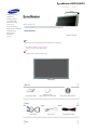
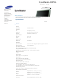
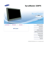
SyncMaster 400PXn/400PX
/460PXn/460PX
Model
Select Language
Install Programs
PDF Manuals
Registration
Safety Instructions
Introduction
Connections
Using the Software
Adjusting the LCD Display
Troubleshooting
Specifications
Information
Appendix
© 2007 Samsung Electronics Co., Ltd. All rights reserved.
Select Language
Main Page
Model
Safety Instructions
Notational
Power
Installation
Clean
Others
Introduction
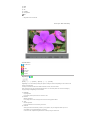
The color and appearance of the product may vary depending on the model, and the product specifications are
Connections
subject to change without prior notice for reasons of performance enhancement.
Using the Software
Adjusting the LCD Display
Safety Instructions
Troubleshooting
Notational
Specifications
Information
Appendix
Please read the following safety instructions as they are designed to prevent damage to property and
harm to the user.
Warning / Caution
Failure to follow directions noted by this symbol could result in bodily harm or damage to the
equipment.
Notational Conventions
Prohibited
Important to read and understand at all times
Do not disassemble
Disconnect the plug from the outlet
Do not touch
Ground to prevent an electric shock
Power
When not used for an extended period of time, set your computer to DPMS.
If using a screen saver, set it to active screen mode.
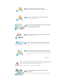
Do not use a damaged or loose plug.
z
This may cause electric shock or fire.
Do not pull the plug out by the wire nor touch the plug with wet
hands.
z
This may cause electric shock or fire.
Use only a properly grounded plug and receptacle.
z
An improper ground may cause electric shock or equipment damage.
Insert the power plug firmly so that it does not come loose.
z
A bad connection may cause fire.
Do not excessively bend the plug and wire nor place heavy objects
upon them, which could cause damage.
z
This may cause electric shock or fire.
Do not connect too many extension cords or plugs to one outlet.
z
This may cause fire.
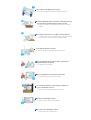
Do not disconnect the power cord while using the LCD Display.
z
A surge may be caused by the separation and may damage the LCD
Display.
Do not use the power cord when the connector or plug is dusty.
z
If the connector or plug of the power cord is dusty, clean it with a dry cloth.
z
Using the power cord with a dusty plug or connector may cause an electric
shock or fire.
Installation
Be sure to contact an authorized the Service Center, when installing your LCD Display in a location
with heavy dust, high or low temperatures, high humidity, and exposed to chemical substances and
where it operates for 24 hours such as at airports, train stations etc.
Failure to do so may cause serious damage to your LCD Display.
Place your LCD Display in a location with low humidity and a
minimum of dust.
z
Failure to do so may cause electric shock or fire inside the LCD Display.
Do not drop the LCD Display when moving it.
This may cause damage to the product or the person carrying it.
z
Install the LCD Display base in a showcase or shelf so that the end
of the base does not protrude from the showcase or shelf.
Dropping the product may cause damage to the product or the person
z
carrying it.
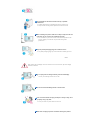
Do not place the product on an unstable or small surface area.
z
Place the product on an even and stable surface ,as the product may fall
and cause harm to someone walking by, specifically children.
Do not place the product on the floor.
Take care, as someone, specifically children may trip over it.
z
Keep any flammable objects such as candles, insecticides or
cigarettes away from the product.
z
Otherwise, this may cause fire.
Keep any heating devices away from the power cable.
z
A melted coating may cause electric shock or fire.
Do not install the product in places with poor ventilation, for
instance, a bookshelf, closet, etc.
z
Any increase in the internal temperature may cause fire.
Put down the LCD Display carefully.
z
Failing to do so may damage the LCD Display.
Do not place the LCD Display face down.
z
This may damage the TFT-LCD surface.
The installation of the bracket must be done by a qualified
professional.
z
Installing the bracket by unqualified personnel may result in injury.
z
Always use the mounting device specified in the owner's manual.
When installing the product, make sure to keep it away from the wall
(more than 10 cm / 4 inches) for ventilation purposes.
z
Poor ventilation may cause an increase in the internal temperature of the
product, resulting in a shortened component life and degraded
performance.
Keep the plastic packaging (bag) out of children's reach.
z
The plastic packaging (bag) may cause suffocation if children play with it.
Clean
When cleaning the LCD Display case or the surface of the TFT -LCD screen, wipe with a slightly
moistened, soft fabric.
Do not spray water or detergent directly onto the LCD Display.
z
This may cause damage, electric shock or fire.
Use the recommended detergent with a smooth cloth.
If the connector between the plug and the pin is dusty or dirty, clean
it properly using a dry cloth.
z
A dirty connector may cause electric shock or fire.
Make sure to unplug the power cord before cleaning the product.
z
Otherwise, this may cause electric shock or fire.
Unplug the power cord from the power outlet and wipe the product
using a soft, dry cloth.
z
Do not use any chemicals such as wax, benzene, alcohol, thinners,
insecticide, air freshener, lubricant or detergent.
Contact the SAMSUNG customer care center or Customer Center for
interior cleaning once a year.
z
Keep the product's interior clean. Dust which has accumulated in the
interior over an extended period of time may cause a malfunction or fire.
Others
Do not remove the cover (or back).
z
This may cause electric shock or fire.
z
Refer to a qualified servicing company.
If your LCD Display does not operate normally - in particular, if there
is any unusual sound or smell coming from the LCD Display unplug it immediately and contact an authorized dealer or the
Service Center.
z
This may cause electric shock or fire.
Keep the product away from places exposed to oil, smoke or
moisture; do not install inside a vehicle.
z
This may cause a malfunction, electric shock or fire.
z
In particular, avoid operating the LCD Display near water or outdoors where
the LCD Display could be exposed to snow or rain.
If the LCD Display is dropped or the casing is damaged, turn the
LCD Display off and unplug the power cord. Then contact the
Service Center.
z
The LCD Display may malfunction, causing electric shock or fire.
Disconnect the plug from the outlet during storms or lightning or if
it is not used for a long period of time.
z
Failure to do so may cause electric shock or fire.
Do not try to move the LCD Display by pulling only the wire or the
signal cable.
z
This may cause a breakdown, electric shock or fire due to damage to the
cable.
Do not move the LCD Display right or left by pulling only the wire or
the signal cable.
z
This may cause a breakdown, electric shock or fire due to damage to the
cable.
Do not cover the vents on the LCD Display cabinet.
z
Bad ventilation may cause a breakdown or fire.
Do not place water containers, chemical products or small metal
objects on the LCD Display.
z
This may cause a malfunction, electric shock or fire.
z
If a foreign substance enters the LCD Display , unplug the power cord and
contact the Service Center.
Keep the product away from combustible chemical sprays or
inflammable substances.
z
This may cause an explosion or fire.
Never insert anything metallic into the LCD Display openings.
z
This may cause electric shock, fire or injury.
Do not insert metal objects such as chopsticks, wire and tools or
inflammable objects such as paper or matches into the vent,
headphone port or AV ports or etc.
z
This may cause electric shock or fire. If an alien substances or water enters
the product, turn the product off, unplug the power connector from the wall
outlet and contact the Service Center.
When viewing a fixed screen for an extended period of time, residual
image or blurriness may appear.
z
Change the mode to energy saving mode or set a screensaver to a
changing picture when away from the LCD Display for an extended period
of time.
Adjusts the resolution and frequency to the level appropriate for the
model.
z
An inappropriate resolution may cause undesirable picture quality.
32 inch (80 cm) - 1360 X 768
Viewing the LCD Display continuously at a too close angle may
result in damage to your eyesight.
To ease eye strain, take at least a five-minute break after every hour
of using the LCD Display.
Do not install the product on an unstable, uneven surface or a
location prone to vibrations.
z
Dropping the product may cause damage to the product or the person
carrying it. Using the product in a location prone to vibrations may shorten
the lifetime of the product or may cause the product to catch fire.
When moving the LCD Display , turn off and unplug the power cord.
Make sure that all cables, including the antenna cable and cables
connected to other devices, are disconnected before moving the
LCD Display.
z
Failure to disconnect cables may damage it and cause fire or electric
shock.
Make sure there are more than two people when moving the
product.
z
Dropping the product may cause a malfunction or injury to the person
carrying it.
Place the product out of children’s reach, as they could damage by
hanging onto it.
z
A falling product may cause injury to the person or even fatality.
When not using the product for an extended period of time, keep the
product unplugged.
z
Otherwise, this may cause heat emission from the accumulated dirt or
degraded insulation, causing electric shock or fire.
Do not place your children's favorite toys or any other objects of
interest on the product.
z
Children may try to climb on the product to retrieve an object. The product
could fall, causing injury or even fatality.
When removing batteries from the remote control, be careful that
they are not swallowed by children. keep the batteries out of
children's reach.
z
If the batteries are swallowed, see a doctor immediately.
When replacing batteries, place the batteries in the correct +/polarity position as indicated on the battery holder.
z
The incorrect polarity may cause a battery to break or leak and may cause
fire, injury, or contamination (damage).
Use only specified standard batteries. Do not use new and used
batteries together.
z
This may cause a battery to break or leak and may cause fire, injury, or
contamination (damage).
The batteries (and rechargeable batteries) is not ordinary refuse and
must be returned for recycling purposes. The customer is
responsible for returning the used or rechargeable batteries for
recycling purposes as the consumer.
z
The customer can return used or rechargeable batteries to a nearby public
recycling center or to a store selling the same type of the battery or
rechargeable battery.
© 1995~2007 SAMSUNG. ALL Rights Reserved
SyncMaster 400PXn/460PXn
Select Language
Main Page
Model
Safety Instructions
Introduction
Package Contents
Your LCD Display
Machanical Layout
Connections
The color and appearance of the product may vary depending on the model, and the product specifications are
Using the Software
subject to change without prior notice for reasons of performance enhancement.
Adjusting the LCD Display
Troubleshooting
Introduction
Specifications
Information
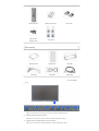
Package Contents
Appendix
Dodatak
Note
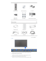
• Please make sure the following items are included with your LCD Display.
ǷȘȐȓȖȎȍȕȐȍ
If any items are missing, contact your dealer.
Contact a local dealer to buy optional items.
Note
• This stand is not for the Floor Standing Type.
LCD Display
Manuals
Quick Setup Guide
Warranty Card
User's Guide, MDC Software,
(Not available in all locations)
MagicNet Software
Cables
D-Sub Cable
Other
Power Cord
Speaker Wire Cable
Remote Control
Batteries (AAA X 2)
Cover-Hole
Semi Stand
USB Holder & Screw (1EA)
BNC to RCA
Adaptor Jack
Sold separately
Wall Mount KIT
Speaker Set
Stand KIT
DVI Cable
LAN Cable
BNC Cable
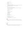
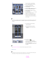
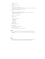
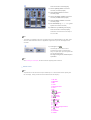
Your LCD Display
Front
1)
MENU
Opens the on-screen menu and exits from the menu or closes the adjustment menu.
2)
Navigate buttons (Up-Down buttons)
Moves from one menu item to another vertically or adjusts selected menu values.
3)
Adjust buttons (Left-Right buttons)/ Volume buttons
Moves from one menu item to another horizontally or adjusts selected menu values.
Adjusts the audio volume.
4)
ENTER
Activates a highlighted menu item.
5)
SOURCE
Switches from PC mode to Video mode.
Changing the source is only allowed for external devices that are connected to the LCD Display at the time.
[PC] → [BNC] → [DVI] → [AV] → [S-Video] → [Component] → [MagicNet]
>> Click here to see an animation clip.
6)
PIP
Push the PIP button to turn the PIP screen On / Off.
More than one PIP cannot overlap on screen as BNC and the component use the same terminal.
>> Click here to see an animation clip.
• PC
AV / S-Video / Component Mode
• BNC
AV / S-Video Mode
• DVI
AV / S-Video / Component Mode
• AV / S-Video
PC / BNC / DVI Mode
• Component
PC / DVI Mode
7)
Power button
Turns the LCD Display On/Off.
8)
Power indicator
Shows PowerSaver mode by blinking green.
9)
Remote Control Sensor
Aim the remote control towards this spot on the LCD Display.
Note
• See PowerSaver described in the manual for further information regarding power saving functions. For
energy conservation, turn your LCD Display OFF when it is not needed or when leaving it unattended for
long periods.
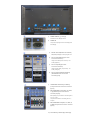
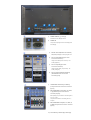
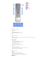
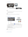
Rear
Note
• For detailed information concerning cable connections, refer to Connecting Cables under Setup. The LCD
Display 's configuration at the back may vary slightly depending on the LCD Display model.
1)
POWER S/W ON [ | ] / OFF [O]
Switches the LCD Display On/Off.
2)
POWER IN
The power cord plugs into the LCD Display and
the wall plug.
3)
RS232C OUT/IN (RS232C Serial PORT)
MDC(Multiple Display Control) Program Port
4)
DVI / PC IN [DVI(HDCP)] (PC Video
Connection Terminal)
Using a DVI Cable (DVI-D to DVI-D) - DVI
mode (Digital PC)
5)
DVI / PC IN [RGB] (PC Video
Connection Terminal)
Using a D-Sub Cable (15 pin D-Sub) - PC
mode (Analog PC)
6)
DVI / PC IN [PC/DVI/BNC AUDIO IN]
(PC/DVI/BNC Audio Connection
Terminal (Input))
7)
COMPONENT AUDIO IN [L-AUDIO-R]
(Component Audio Connection Terminal
(Input))
8)
BNC/COMPONENT OUT [R/PR, G/Y, B/PB,
H, V] (BNC/Component Connection
Terminal (Output))
BNC (Analog PC) Connection: connecting the R,
G, B, H, V ports
Component Connection: connecting the PR, Y,
PB ports
9)
BNC/COMPONENT IN [R/PR, G/Y, B/PB, H,
V] (BNC/Component Connection Terminal
(Input))
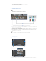
10) AV AUDIO IN [L-AUDIO-R] (LCD Display
Audio Connection Terminal (Input))
11) AV OUT [VIDEO] (VIDEO Connection
Terminal): AV mode (Output)
12) AV IN [VIDEO] (VIDEO Connection
Terminal) (Input)
13) AV OUT [S-VIDEO] (S-VIDEO Connection
Terminal): S-VIDEO mode (Output)
14) AV IN [S-VIDEO] (S-VIDEO Connection
Terminal) (Input)
15) EXT SPEAKER(8 Ω)[- - L - +, - - R - +] (EXT
Speaker Connection Terminal)
16) AUDIO OUT [L-AUDIO-R] (LCD Display
Audio Connection Terminal (Output))
AUDIO OUT is the terminal for sound output of
PC, DVI or BNC.
Note
• The number of LCD Display s that can be connected to loopout may differ depending on the cables, signal
source etc. With cables where there is no degradation or signal source, up to ten LCD Displays can be
connected.
17) LAN (LAN Connection Terminal)
MS Internet Explorer
18) USB (USB Connection Terminal)
Keyboard / Mouse, Mass Storage Device
Compatible.
19) Kensington Lock
The Kensington lock is a device used to
physically fix the system to something when
using it in a public place. (The locking device has
to be purchased separately.)
For using a locking device, contact the place
of purchase.
Note
• See Connecting the LCD Display for further information regarding cable connections.
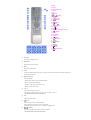
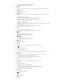
Remote Control
Note
• The performance of the remote control may be affected by a TV or other electronic device operating near
the LCD Display , causing a malfunction due to interference with the frequency.
1. ON / OFF
2. MAGICNET
3. MDC
4. LOCK
5. MagicNet buttons
6.+100 -/-7. VOL
8.
MUTE
9.
TTX/MIX
10.
MENU
11.
ENTER
12.
P.MODE
13. AUTO
14.
PRE-CH
15 . CH/P
16.
SOURCE
17.
INFO
18.
EXIT
19. Up-Down Left-Right buttons
20.
S.MODE
21. STILL
22. FM RADIO
23. P.SIZE
24.
25.
SRS
DUAL/MTS
26.
PIP
27.
SOURCE
28. SWAP
29.
30.
31.
32.
33.
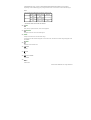
1)
SIZE
REW
STOP
PLAY/PAUSE
FF
ON / OFF
Turns the LCD Display On/Off.
2)
MAGICNET
MagicNet Quick Launch Button.
3)
MDC
MDC Quick Launch Button.
4)
LOCK
Activates or deactivates all function keys on both the remote control and the LCD Display except for the
Power and LOCK buttons.
5)
MagicNet buttons
Used for MagicNet.
• Alphanumeric: Used to enter the Internet address.
• DEL: Functions as the backspace.
• SYMBOL: Used to enter the symbols. (.O_-)
• ENTER: Used to enter values.
6)
+100 -/-Press to select channels over 100.
For example, to select channel 121, press "+100", then press "2" and "1".
- This fuction does not work for this monitor.
7)
VOL
Adjusts the audio volume.
8)
MUTE
Pauses (mutes) the audio output temporarily.
This is displayed on the lower left corner of the screen.
The audio resumes if MUTE or - VOL + is pressed in the Mute mode.
9)
TTX/MIX
TV channels provide text information services via teletext.
- This fuction does not work for this monitor.
10)
MENU
Opens the on-screen menu and exits from the menu screen or closes the screen adjustment menu.
ENTER
11)
Activates a highlighted menu item.
12)
P.MODE
When you press this button, current picture mode is displayed on the lower center of the screen.
AV / S-Video / Component : P.MODE
The Monitor has four automatic picture settings that are preset at the factory.
Then push button again to circle through available preconfigured modes.
( Dynamic → Standard → Movie → Custom )
PC/DVI/BNC : M/B (MagicBright)
MagicBright™ is a new feature providing the optimum viewing environment depending on the contents of
the image you are watching.
Then push button again to circle through available preconfigured modes.
(Entertain → Internet → Text → Custom )
13) AUTO
Adjusts the screen display automatically in PC mode.
By changing the resolution in the control panel, auto function is performed.
14)
PRE-CH
Returns to the immediately previous channel.
- This fuction does not work for this monitor.
15)
CH/P
In TV mode, selects TV channels.
- This fuction does not work for this monitor.
16)
SOURCE
Changes the video source.
17)
INFO
The current picture information is displayed in the top left corner of the screen.
EXIT
18)
Exits from the menu screen.
19) Up-Down Left-Right buttons
Moves from one menu item to another horizontally, vertically or adjusts selected menu values.
20)
S.MODE
When pressing this button, the current mode is displayed at the bottom centre of the screen.
The LCD Display has a built-in high fidelity stereo amplifier.
Then press the button again to circle through available preconfigured modes.
( Standard → Music → Movie → Speech → Custom )
21) STILL
Press the button once to freeze the screen. Press it again to unfreeze.
22) FM RADIO
Turns the FM Radio on/off.
In PC/DVI mode, sets the SOUND to FM Radio.
In general Video mode, selects FM Radio, and turns off the screen.
In areas where the signal is weak, noise may occur during FM radio broadcasts.
- This fuction does not work for this monitor.
23) P.SIZE
Press to change the screen size.
SRS
24)
SRS
25)
DUAL/MTS
DUALSTEREO/MONO, DUAL l / DUAL ll and MONO/NICAM MONO/NICAM STEREO can be operated
depending on the broadcasting type by using the DUAL button on the remote control while watching TV.
MTSYou can select MTS (Multichannel Television Stereo) mode.
Audio Type MTS/S_Mode
FM Stereo
Mono
Mono
Stereo
Mono ↔ Stereo
SAP
Mono ↔ SAP
Default
Manual Change
Mono
- This fuction does not work for this monitor.
26)
PIP
Every time you press the button, a PIP screen appears.
27)
SOURCE
Changes the source of the PIP window signal.
28) SWAP
Swaps the contents of the PIP and main image.
The image in the PIP window will appear on the main screen, and the main screen image will appear in the
PIP window.
29)
SIZE
Switches the PIP Picture Size.
30)
REW
Rewind
31)
STOP
Stop
32)
PLAY / PAUSE
Play/Pause
33)
FF
Fast forward
© 1995~2007 SAMSUNG. ALL Right Reserved
SyncMaster 400PX/460PX
Select Language
Main Page
Model
Safety Instructions
Introduction
Package Contents
Your LCD Display
Machanical Layout
Connections
The color and appearance of the product may vary depending on the model, and the product specifications are
Using the Software
subject to change without prior notice for reasons of performance enhancement.
Adjusting the LCD Display
Troubleshooting
Introduction
Specifications
Information
Package Contents
Appendix
Dodatak
Note
• Please make sure the following items are included with your LCD Display.
ǷȘȐȓȖȎȍȕȐȍ
If any items are missing, contact your dealer.
Contact a local dealer to buy optional items.
Note
• This stand is not for the Floor Standing Type.
LCD Display
Manuals
Quick Setup Guide
Warranty Card
(Not available in all locations)
User's Guide, MDC Software
Cables
D-Sub Cable
Other
Power Cord
Speaker Wire Cable
Remote Control
Batteries (AAA X 2)
BNC to RCA
Adaptor Jack
Cover-Hole
Semi Stand
Sold separately
Wall Mount KIT
Speaker Set
Stand KIT
DVI Cable
LAN Cable
BNC Cable
Your LCD Display
Front
1)
MENU
Opens the on-screen menu and exits from the menu or closes the adjustment menu.
2)
Navigate buttons (Up-Down buttons)
Moves from one menu item to another vertically or adjusts selected menu values.
3)
Adjust buttons (Left-Right buttons)/ Volume buttons
Moves from one menu item to another horizontally or adjusts selected menu values.
Adjusts the audio volume.
4)
ENTER
Activates a highlighted menu item.
5)
SOURCE
Switches from PC mode to Video mode.
Changing the source is only allowed for external devices that are connected to the LCD Display at the time.
[PC] → [BNC] → [DVI] → [AV] → [S-Video] → [Component]
>> Click here to see an animation clip.
6)
PIP
Push the PIP button to turn the PIP screen On / Off.
More than one PIP cannot overlap on screen as BNC and the component use the same terminal.
>> Click here to see an animation clip.
• PC
AV / S-Video / Component Mode
• BNC
AV / S-Video Mode
• DVI
AV / S-Video / Component Mode
• AV / S-Video
PC / BNC / DVI Mode
• Component
PC / DVI Mode
7)
Power button
Turns the LCD Display On/Off.
8)
Power indicator
Shows PowerSaver mode by blinking green.
9)
Remote Control Sensor
Aim the remote control towards this spot on the LCD Display.
Note
• See PowerSaver described in the manual for further information regarding power saving functions. For
energy conservation, turn your LCD Display OFF when it is not needed or when leaving it unattended for
long periods.
Rear
Note
• For detailed information concerning cable connections, refer to Connecting Cables under Setup. The LCD
Display 's configuration at the back may vary slightly depending on the LCD Display model.
1)
POWER S/W ON [ | ] / OFF [O]
Switches the LCD Display On/Off.
2)
POWER IN
The power cord plugs into the LCD Display and
the wall plug.
3)
RS232C OUT/IN (RS232C Serial PORT)
MDC(Multiple Display Control) Program Port
4)
DVI / PC IN [DVI(HDCP)] (PC Video
Connection Terminal)
Using a DVI Cable (DVI-D to DVI-D) - DVI
mode (Digital PC)
5)
DVI / PC IN [RGB] (PC Video
Connection Terminal)
Using a D-Sub Cable (15 pin D-Sub) - PC
mode (Analog PC)
6)
DVI / PC IN [PC/DVI/BNC AUDIO IN]
(PC/DVI/BNC Audio Connection
Terminal (Input))
7)
COMPONENT AUDIO IN [L-AUDIO-R]
(Component Audio Connection Terminal
(Input))
8)
BNC/COMPONENT OUT [R/PR, G/Y, B/PB,
H, V] (BNC/Component Connection
Terminal (Output))
BNC (Analog PC) Connection: connecting the R,
G, B, H, V ports
Component Connection: connecting the PR, Y,
PB ports
9)
BNC/COMPONENT IN [R/PR, G/Y, B/PB, H,
V] (BNC/Component Connection Terminal
(Input))
10) AV AUDIO IN [L-AUDIO-R] (LCD Display
Audio Connection Terminal (Input))
11) AV OUT [VIDEO] (VIDEO Connection
Terminal): AV mode (Output)
12) AV IN [VIDEO] (VIDEO Connection
Terminal) (Input)
13) AV OUT [S-VIDEO] (S-VIDEO Connection
Terminal): S-VIDEO mode (Output)
14) AV IN [S-VIDEO] (S-VIDEO Connection
Terminal) (Input)
15) EXT SPEAKER(8 Ω)[- - L - +, - - R - +] (EXT
Speaker Connection Terminal)
16) AUDIO OUT [L-AUDIO-R] (LCD Display
Audio Connection Terminal (Output))
AUDIO OUT is the terminal for sound output of
PC, DVI or BNC.
Note
• The number of LCD Display s that can be connected to loopout may differ depending on the cables, signal
source etc. With cables where there is no degradation or signal source, up to ten LCD Displays can be
connected.
17) Kensington Lock
The Kensington lock is a device used to
physically fix the system to something when
using it in a public place. (The locking device has
to be purchased separately.)
For using a locking device, contact the place
of purchase.
Note
• See Connecting the LCD Display for further information regarding cable connections.
Remote Control
Note
• The performance of the remote control may be affected by a TV or other electronic device operating near
the LCD Display , causing a malfunction due to interference with the frequency.
1. ON / OFF
2. MAGICNET
3. MDC
4. LOCK
5. MagicNet buttons
6.+100 -/-7. VOL
8.
MUTE
9.
TTX/MIX
10.
MENU
11.
ENTER
12.
P.MODE
13. AUTO
14.
PRE-CH
15 . CH/P
16.
SOURCE
17.
INFO
18.
EXIT
19. Up-Down Left-Right buttons
20.
S.MODE
21. STILL
22. FM RADIO
23. P.SIZE
24.
25.
SRS
DUAL/MTS
26.
PIP
27.
SOURCE
28. SWAP
29.
30.
31.
32.
33.
1)
SIZE
REW
STOP
PLAY/PAUSE
FF
ON / OFF
Turns the LCD Display On/Off.
2)
MAGICNET
MagicNet Quick Launch Button.
- This fuction does not work for this monitor.
3)
MDC
MDC Quick Launch Button.
4)
LOCK
Activates or deactivates all function keys on both the remote control and the LCD Display except for the
Power and LOCK buttons.
5)
MagicNet buttons
Used for MagicNet.
• Alphanumeric: Used to enter the Internet address.
• DEL: Functions as the backspace.
• SYMBOL: Used to enter the symbols. (.O_-)
• ENTER: Used to enter values.
- This fuction does not work for this monitor.
6)
+100 -/-Press to select channels over 100.
For example, to select channel 121, press "+100", then press "2" and "1".
- This fuction does not work for this monitor.
7)
VOL
Adjusts the audio volume.
8)
MUTE
Pauses (mutes) the audio output temporarily.
This is displayed on the lower left corner of the screen.
The audio resumes if MUTE or - VOL + is pressed in the Mute mode.
9)
TTX/MIX
TV channels provide text information services via teletext.
- This fuction does not work for this monitor.
10)
MENU
Opens the on-screen menu and exits from the menu screen or closes the screen adjustment menu.
ENTER
11)
Activates a highlighted menu item.
12)
P.MODE
When you press this button, current picture mode is displayed on the lower center of the screen.
AV / S-Video / Component : P.MODE
The Monitor has four automatic picture settings that are preset at the factory.
Then push button again to circle through available preconfigured modes.
( Dynamic → Standard → Movie → Custom )
PC/DVI/BNC : M/B (MagicBright)
MagicBright™ is a new feature providing the optimum viewing environment depending on the contents of
the image you are watching.
Then push button again to circle through available preconfigured modes.
(Entertain → Internet → Text → Custom )
13) AUTO
Adjusts the screen display automatically in PC mode.
By changing the resolution in the control panel, auto function is performed.
14)
PRE-CH
Returns to the immediately previous channel.
- This fuction does not work for this monitor.
15)
CH/P
In TV mode, selects TV channels.
- This fuction does not work for this monitor.
16)
SOURCE
Changes the video source.
17)
INFO
The current picture information is displayed in the top left corner of the screen.
EXIT
18)
Exits from the menu screen.
19) Up-Down Left-Right buttons
Moves from one menu item to another horizontally, vertically or adjusts selected menu values.
20)
S.MODE
When pressing this button, the current mode is displayed at the bottom centre of the screen.
The LCD Display has a built-in high fidelity stereo amplifier.
Then press the button again to circle through available preconfigured modes.
( Standard → Music → Movie → Speech → Custom )
21) STILL
Press the button once to freeze the screen. Press it again to unfreeze.
22) FM RADIO
Turns the FM Radio on/off.
In PC/DVI mode, sets the SOUND to FM Radio.
In general Video mode, selects FM Radio, and turns off the screen.
In areas where the signal is weak, noise may occur during FM radio broadcasts.
- This fuction does not work for this monitor.
23) P.SIZE
Press to change the screen size.
SRS
24)
SRS
25)
DUAL/MTS
DUAL-
STEREO/MONO, DUAL l / DUAL ll and MONO/NICAM MONO/NICAM STEREO can be operated
depending on the broadcasting type by using the DUAL button on the remote control while watching TV.
MTSYou can select MTS (Multichannel Television Stereo) mode.
Audio Type MTS/S_Mode
FM Stereo
Mono
Mono
Stereo
Mono ↔ Stereo
SAP
Mono ↔ SAP
Default
Manual Change
Mono
- This fuction does not work for this monitor.
26)
PIP
Every time you press the button, a PIP screen appears.
27)
SOURCE
Changes the source of the PIP window signal.
28) SWAP
Swaps the contents of the PIP and main image.
The image in the PIP window will appear on the main screen, and the main screen image will appear in the
PIP window.
29)
SIZE
Switches the PIP Picture Size.
30)
REW
Rewind
31)
STOP
Stop
32)
PLAY / PAUSE
Play/Pause
33)
FF
Fast forward
© 1995~2007 SAMSUNG. ALL Right Reserved
SyncMaster 400PXn/400PX
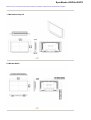
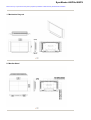
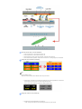
Mechanical Lay-out | Monitor Head | Stand | Speaker | Installation VESA Bracket | Wall Bracket Installation
1. Mechanical Lay-out
Dodatak
ǷȘȐȓȖȎȍȕȐȍ
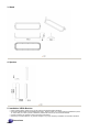
2. Monitor Head
3. Stand
4. Speaker
5. Installation VESA Bracket
z
z
z
z
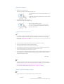
When installing VESA, make sure to comply with the international VESA standards.
Purchasing VESA Bracket and Installation Information : Please contact your nearest Samsung Distributor to place
an order. After your order is placed, installation professionals will visit you and install the bracket.
At least 2 persons are needed in order to move the LCD Monitor.
Samsung is not responsible for any product damage or any injury caused by installation at customer's discretion.
Dimensions
For securing the bracket on a wall, use only machine screws of 6 mm diameter and 8 to 12 mm length.
6. Wall Bracket Installation
z
z
z
Contact a technician for installing the wall bracket.
Samsung Electronics is not responsible for any damages to the product or harm to customers when the
installation is done by the customer.
This product is for installing on cement walls. The product may not stay in place when installed on plaster or wood.
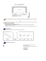
Components
Only use the components and accessories shipped with the product.
`
Wall Bracket
(1)
Hinge
(Left 1, Right 1)
Plastic Hanger Screw(A)
(4)
(11)
Screw(B)
(4)
Anchor
(11)
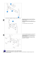
Wall Bracket Assembly
Insert and tighten the Captive Screw in the
direction of the arrow.
When done, mount the wall bracket on the wall.
A. Captive Screw
B. Wall Bracket
C. Hinge (Left)
D. Hinge (Right)
There are two hinges(left and right). Use the correct one.
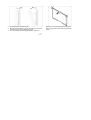
Before drilling into the wall, check if the length
between the two locking holes at the back of the
product is correct.
If the length is too short or long, loosen all or
some of the 4screws on the wall bracket to adjust
the length.
A. Length between the two locking holes
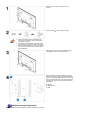
Check the installation diagram and mark the drill
points on the wall. Use the 5.0 mm bit to drill
holes deeper than 35 mm. Fix each anchor in the
corresponding hole.
Match each of the brackets and hinge holes to
the corresponding anchor holes and insert and
tighten the 11 screws A.
To mount the product on the wall bracket
The shape of the product may vary depending on the model. (The assemblies of the plastic hanger and the
screw are the same)
Remove the 4 screws on the back of the
product.
Insert the screw B into the plastic hanger.
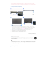
1. Mount the product on the wall bracket and
make sure it is properly fixed to the left and
right plastic hangers.
2. Be careful when installing the product on the
bracket as fingers can be caught in the holes.
3. Make sure the wall bracket is securely fixed to
the wall, or the product may not stay in place
after installation.
Tighten the 4 screws in step 2 (plastic hanger +
screw B)to the rear holes of the product.
Remove safety pin (3) and insert the 4 product
holders into the corresponding bracket holes (1).
Then place the product(2) so that it is firmly fixed
to the bracket. Make sure to re-insert and tighten
the safety pin (3) to securely hold the product to
the bracket.
A. Monitor
B. Wall Bracket
C. Wall
Wall Bracket Angle Adjustment
Adjust the bracket angle to -2°before installing it on the wall.
1. Fix the product to the wall bracket.
2. Hold the product at the top in the center and pull it forward
(direction of the arrow) to adjust the angle.
3. You can adjust the bracket angle between -2°and 15 °.
Make sure to use the top center, and not the
leftor the right side of the product to adjust the
angle.
SyncMaster 460PXn/460PX
Mechanical Lay-out | Monitor Head | Stand | Speaker | Installation VESA Bracket | Wall Bracket Installation
1. Mechanical Lay-out
Dodatak
ǷȘȐȓȖȎȍȕȐȍ
2. Monitor Head
3. Stand
4. Speaker
5. Installation VESA Bracket
z
z
z
z
When installing VESA, make sure to comply with the international VESA standards.
Purchasing VESA Bracket and Installation Information : Please contact your nearest Samsung Distributor to place
an order. After your order is placed, installation professionals will visit you and install the bracket.
At least 2 persons are needed in order to move the LCD Monitor.
Samsung is not responsible for any product damage or any injury caused by installation at customer's discretion.
Dimensions
For securing the bracket on a wall, use only machine screws of 6 mm diameter and 8 to 12 mm length.
6. Wall Bracket Installation
z
z
z
Contact a technician for installing the wall bracket.
Samsung Electronics is not responsible for any damages to the product or harm to customers when the
installation is done by the customer.
This product is for installing on cement walls. The product may not stay in place when installed on plaster or wood.
Components
Only use the components and accessories shipped with the product.
`
Wall Bracket
(1)
Hinge
(Left 1, Right 1)
Plastic Hanger Screw(A)
(4)
(11)
Screw(B)
(4)
Anchor
(11)
Wall Bracket Assembly
Insert and tighten the Captive Screw in the
direction of the arrow.
When done, mount the wall bracket on the wall.
A. Captive Screw
B. Wall Bracket
C. Hinge (Left)
D. Hinge (Right)
There are two hinges(left and right). Use the correct one.
Before drilling into the wall, check if the length
between the two locking holes at the back of the
product is correct.
If the length is too short or long, loosen all or
some of the 4screws on the wall bracket to adjust
the length.
A. Length between the two locking holes
Check the installation diagram and mark the drill
points on the wall. Use the 5.0 mm bit to drill
holes deeper than 35 mm. Fix each anchor in the
corresponding hole.
Match each of the brackets and hinge holes to
the corresponding anchor holes and insert and
tighten the 11 screws A.
To mount the product on the wall bracket
The shape of the product may vary depending on the model. (The assemblies of the plastic hanger and the
screw are the same)
Remove the 4 screws on the back of the
product.
Insert the screw B into the plastic hanger.
1. Mount the product on the wall bracket and
make sure it is properly fixed to the left and
right plastic hangers.
2. Be careful when installing the product on the
bracket as fingers can be caught in the holes.
3. Make sure the wall bracket is securely fixed to
the wall, or the product may not stay in place
after installation.
Tighten the 4 screws in step 2 (plastic hanger +
screw B)to the rear holes of the product.
Remove safety pin (3) and insert the 4 product
holders into the corresponding bracket holes (1).
Then place the product(2) so that it is firmly fixed
to the bracket. Make sure to re-insert and tighten
the safety pin (3) to securely hold the product to
the bracket.
A. Monitor
B. Wall Bracket
C. Wall
Wall Bracket Angle Adjustment
Adjust the bracket angle to -2°before installing it on the wall.
1. Fix the product to the wall bracket.
2. Hold the product at the top in the center and pull it forward
(direction of the arrow) to adjust the angle.
3. You can adjust the bracket angle between -2°and 15 °.
Make sure to use the top center, and not the
leftor the right side of the product to adjust the
angle.
SyncMaster 400PXn/460PXn
Select Language
Main Page
Model
Safety Instructions
Introduction
Connections
Installing the Stand KIT
Connecting the LCD
Display
The color and appearance of the product may vary depending on the model, and the product specifications are
Using the Software
subject to change without prior notice for reasons of performance enhancement.
Adjusting the LCD Display
Troubleshooting
Connections
Specifications
Information
Installing the Stand KIT
Appendix
Dodatak
Note
• Only the supplied bolts should be used.
ǷȘȐȓȖȎȍȕȐȍ
Caution
Samsung Electronics will not be responsible for damages caused by using a base other than those
specified.
Installing the Semi Stand
Left stand
Right stand
Caution
Make sure to install the stand with the Caution label
folded backwards.
1)
A 'Cover-Protector' is used to protect the hole at the bottom of the LCD Display , where the stand is
inserted. Be sure to remove the 'Cover-Protector' when attaching the provided Semi Stand or Stand KIT
(sold separately) and cover the hole using the 'Cover-Hole' when attaching the wall mount kit.
2)
Set up the left and right stands respectively.
3)
Insert the stand into the hole at the bottom of the LCD Display.
Insert the screw into the hole indicated and tighten it. (M4 x L15)
Caution
This stand is designed for adjusting the screen angle. The company is not responsible for any problem
caused when using this stand. Under no circumstances use the product as a stand for placing something on.
Installing the Stand KIT (sold separately)
1)
A 'Cover-Protector' is used to protect the hole at the bottom of the LCD Display , where the stand is
inserted. Be sure to remove the 'Cover-Protector' when attaching the provided Semi Stand or Stand KIT
(sold separately) and cover the hole using the 'Cover-Hole' when attaching the wall mount kit.
2)
Ensure that the parts are inserted in the right direction and in the right place. (M4 × L15)
3)
Insert the stand into the hole at the bottom of the LCD Display.
4)
Insert the screw into the hole indicated and tighten it. (M4 × L15)
Connecting the LCD Display
Using a Power cord with Earth
In the event of failure, the earth lead may cause electric shock. Make sure to wire the earth lead in
correctly, before connecting the AC power. When un-wiring the earth lead, make sure to disconnect
the AC power in advance.
Note
• AV input devices such as DVD players, VCR's or camcorders as well as your computer can be connected
to the LCD Display. For detailed information on connecting AV input devices, refer to the User Controls
under Adjusting Your LCD Display.
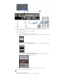
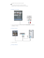
Connecting to a Computer
1)
Connect the power cord for your LCD Display to the power port on the back of the LCD Display.
Trun on the power switch.
2)
There are 3 ways to connect the D-sub to your LCD Display.
Choose one of the following:
2-1)
Using the D-sub (Analog) connector on the video card.
Connect the D-sub to the 15-pin, RGB port on the back of your LCD Display and the 15 pin D-sub
Port on the computer.
2-2)
Using the DVI (Digital) connector on the video card.
Connect the DVI Cable to the DVI(HDCP) port on the back of your LCD Display and the DVI port
on the computer.
2-3)
Using the BNC (Analog) connector on the video card.
Connect the BNC Cable to the BNC/COMPONENT IN - R, G, B, H, V ports on the back of your
LCD Display and the 15 pin D-sub Port on the computer.
3)
Connect the audio cable for your LCD Display to the audio port on the back of your computer.
4)
Turn on both your computer and the LCD Display.
Note
• The DVI cable or BNC cable is optional.
Contact a local Samsung Electronics Service Center to buy optional items.
Connecting Digital DVD
Note
• Input devices such as digital DVD are connected to the DVI IN terminal of the monitor using the DVI cable.
• Then, start the DVD with a DVD disc inserted.
• Select Digital using the SOURCE button.
Note
• The monitor has DVI IN connection terminals to connect DVI input devices digital DVD.
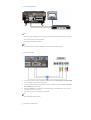
Connecting to a VCR
1)
AV input devices such as VCRs or Camcorders are connected via the AV IN [VIDEO] or AV IN [S-VIDEO]
of the LCD Display using an S-VHS or BNC cable.
2)
Connect the Audio (L) and Audio (R) terminals of a VCR or Camcorders to the LCD Display 's AV AUDIO
IN [L-AUDIO-R] using audio cables.
3)
Select AV or S-Video for a connected VCR or Camcorder using the SOURCE button on the front of the
LCD Display or on the remote control.
4)
Then, start the VCR or Camcorders with a tape inserted.
Note
• The S-VHS or BNC cable is optional.
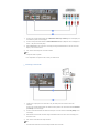
Connecting to a DVD Player
1)
Connect a set of audio cables between the COMPONENT AUDIO IN [L-AUDIO-R] on the LCD Display and
the AUDIO OUT jacks on the DVD player.
2)
Connect a Component cable between the BNC/COMPONENT IN - PR, Y, PB port on the LCD Display and
the PR, Y, PB jacks on the DVD player.
3)
Select Component for the connection to a DVD player using the SOURCE button on the front of the LCD
Display or on the remote control.
4)
Then, start the DVD Player with a DVD disc inserted.
Note
• A component cable is optional.
For an explanation of Component video, consult your DVD manual.
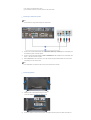
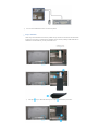
Connecting to a Camcorder
1)
Locate the A/V output jacks on the camcorder. They are usually found on the side or back of the
camcorder.
Connect a set of audio cables between the AUDIO OUTPUT jacks on the camcorder and the AV AUDIO IN
[L-AUDIO-R] on the LCD Display.
2)
Connect a video cable between the VIDEO OUTPUT jack on the camcorder and the AV IN [VIDEO] on the
LCD Display.
3)
Select AV for the Camcorder connection using the SOURCE button on the front of the LCD Display or on
the remote control.
4)
Then, start the Camcorders with a tape inserted.
Note
• The audio-video cables shown here are usually included with a Camcorder.
(If not, check your local electronics store.)
If your camcorder is stereo, you need to connect a set of two cables.
Connecting to a DTV Set Top Box
Note
• The connections for a typical Set Top Box are shown below.
1)
Connect a set of audio cables between the COMPONENT AUDIO IN [L-AUDIO-R] on the LCD Display and
the AUDIO OUT jacks on the Set Top Box.
2)
Connect a Component cable between the BNC / COMPONENT IN - PR, Y, PB port on the LCD Display and
the PR, Y, PB jacks on the Set Top Box.
3)
Select Component for the connection to a DTV Set Top Box using the SOURCE button on the front of the
LCD Display or on the remote control.
Note
• For an explanation of Component video, see your Set Top Box owner's manual.
Connecting Speakers
1)
Fasten the SET and the speaker using the screws.
* Mount the speaker set without the speaker stand.
2)
Connect the speaker connection cable between the speaker connection jack on the back of the SET and
the speaker connection jack on the back of the speaker.
Note
• Do not move the SET while the SET is connected to the speakers.
The speaker-bracket for connecting the SET speaker my become damaged.
Connecting to an Audio System
1)
Connect a set of audio cables between the AUX L, R jacks on the AUDIO SYSTEM and the AUDIO OUT
[L-AUDIO-R] on LCD Display.
Connecting a LAN Cable
1)
Connect the LAN cable.
Connecting a USB device
1)
You can connect USB devices such as a mouse or keyboard.
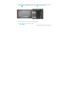
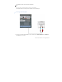
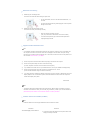
Using a USB Holder
When using a small external device such as a portable memory stick and it is connected to the USB terminal
at the back of your monitor, it is exposed to the possiblity of theft or loss. By installing a USB holder after the
installation of an external device, you can prevent theft or loss.
1)
Insert part
of your USB holder into the groove in part
at the back of your monitor.
2)
3)
Align part
of your USB holder with the groove at the bottom of part
Align part
of your USB holder with the bottom of part
at the back of your monitor.
at the back of your monitor.
Insert a screw into the groove aligned in step [2], and fasten it.
Align
with
and use a screw to fix them.
© 1995~2007 SAMSUNG. ALL Right Reserved
SyncMaster 400PX/460PX
Select Language
Main Page
Model
Safety Instructions
Introduction
Connections
Installing the Stand KIT
Connecting the LCD
Display
The color and appearance of the product may vary depending on the model, and the product specifications are
Using the Software
subject to change without prior notice for reasons of performance enhancement.
Adjusting the LCD Display
Troubleshooting
Connections
Specifications
Information
Installing the Stand KIT
Appendix
Dodatak
Note
• Only the supplied bolts should be used.
ǷȘȐȓȖȎȍȕȐȍ
Caution
Samsung Electronics will not be responsible for damages caused by using a base other than those
specified.
Installing the Semi Stand
Left stand
Right stand
Caution
Make sure to install the stand with the Caution label
folded backwards.
1)
A 'Cover-Protector' is used to protect the hole at the bottom of the LCD Display , where the stand is
inserted. Be sure to remove the 'Cover-Protector' when attaching the provided Semi Stand or Stand KIT
(sold separately) and cover the hole using the 'Cover-Hole' when attaching the wall mount kit.
2)
Set up the left and right stands respectively.
3)
Insert the stand into the hole at the bottom of the LCD Display.
Insert the screw into the hole indicated and tighten it. (M4 x L15)
Caution
This stand is designed for adjusting the screen angle. The company is not responsible for any problem
caused when using this stand. Under no circumstances use the product as a stand for placing something on.
Installing the Stand KIT (sold separately)
1)
A 'Cover-Protector' is used to protect the hole at the bottom of the LCD Display , where the stand is
inserted. Be sure to remove the 'Cover-Protector' when attaching the provided Semi Stand or Stand KIT
(sold separately) and cover the hole using the 'Cover-Hole' when attaching the wall mount kit.
2)
Ensure that the parts are inserted in the right direction and in the right place. (M4 × L15)
3)
Insert the stand into the hole at the bottom of the LCD Display.
4)
Insert the screw into the hole indicated and tighten it. (M4 × L15)
Connecting the LCD Display
Using a Power cord with Earth
In the event of failure, the earth lead may cause electric shock. Make sure to wire the earth lead in
correctly, before connecting the AC power. When un-wiring the earth lead, make sure to disconnect
the AC power in advance.
Note
• AV input devices such as DVD players, VCR's or camcorders as well as your computer can be connected
to the LCD Display. For detailed information on connecting AV input devices, refer to the User Controls
under Adjusting Your LCD Display.
Connecting to a Computer
1)
Connect the power cord for your LCD Display to the power port on the back of the LCD Display.
Trun on the power switch.
2)
There are 3 ways to connect the D-sub to your LCD Display.
Choose one of the following:
2-1)
Using the D-sub (Analog) connector on the video card.
Connect the D-sub to the 15-pin, RGB port on the back of your LCD Display and the 15 pin D-sub
Port on the computer.
2-2)
Using the DVI (Digital) connector on the video card.
Connect the DVI Cable to the DVI(HDCP) port on the back of your LCD Display and the DVI port
on the computer.
2-3)
Using the BNC (Analog) connector on the video card.
Connect the BNC Cable to the BNC/COMPONENT IN - R, G, B, H, V ports on the back of your
LCD Display and the 15 pin D-sub Port on the computer.
3)
Connect the audio cable for your LCD Display to the audio port on the back of your computer.
4)
Turn on both your computer and the LCD Display.
Note
• The DVI cable or BNC cable is optional.
Contact a local Samsung Electronics Service Center to buy optional items.
Connecting Digital DVD
Note
• Input devices such as digital DVD are connected to the DVI IN terminal of the monitor using the DVI cable.
• Then, start the DVD with a DVD disc inserted.
• Select Digital using the SOURCE button.
Note
• The monitor has DVI IN connection terminals to connect DVI input devices digital DVD.
Connecting to a VCR
1)
AV input devices such as VCRs or Camcorders are connected via the AV IN [VIDEO] or AV IN [S-VIDEO]
of the LCD Display using an S-VHS or BNC cable.
2)
Connect the Audio (L) and Audio (R) terminals of a VCR or Camcorders to the LCD Display 's AV AUDIO
IN [L-AUDIO-R] using audio cables.
3)
Select AV or S-Video for a connected VCR or Camcorder using the SOURCE button on the front of the
LCD Display or on the remote control.
4)
Then, start the VCR or Camcorders with a tape inserted.
Note
• The S-VHS or BNC cable is optional.
Connecting to a DVD Player
1)
Connect a set of audio cables between the COMPONENT AUDIO IN [L-AUDIO-R] on the LCD Display and
the AUDIO OUT jacks on the DVD player.
2)
Connect a Component cable between the BNC/COMPONENT IN - PR, Y, PB port on the LCD Display and
the PR, Y, PB jacks on the DVD player.
3)
Select Component for the connection to a DVD player using the SOURCE button on the front of the LCD
Display or on the remote control.
4)
Then, start the DVD Player with a DVD disc inserted.
Note
• A component cable is optional.
For an explanation of Component video, consult your DVD manual.
Connecting to a Camcorder
1)
Locate the A/V output jacks on the camcorder. They are usually found on the side or back of the
camcorder.
Connect a set of audio cables between the AUDIO OUTPUT jacks on the camcorder and the AV AUDIO IN
[L-AUDIO-R] on the LCD Display.
2)
Connect a video cable between the VIDEO OUTPUT jack on the camcorder and the AV IN [VIDEO] on the
LCD Display.
3)
Select AV for the Camcorder connection using the SOURCE button on the front of the LCD Display or on
the remote control.
4)
Then, start the Camcorders with a tape inserted.
Note
• The audio-video cables shown here are usually included with a Camcorder.
(If not, check your local electronics store.)
If your camcorder is stereo, you need to connect a set of two cables.
Connecting to a DTV Set Top Box
Note
• The connections for a typical Set Top Box are shown below.
1)
Connect a Component cable between the BNC / COMPONENT IN - PR, Y, PB port on the LCD Display and
the PR, Y, PB jacks on the Set Top Box.
2)
Connect a set of audio cables between the COMPONENT AUDIO IN [L-AUDIO-R] on the LCD Display and
the AUDIO OUT jacks on the Set Top Box.
3)
Select Component for the connection to a DTV Set Top Box using the SOURCE button on the front of the
LCD Display or on the remote control.
Note
• For an explanation of Component video, see your Set Top Box owner's manual.
Connecting Speakers
1)
Fasten the SET and the speaker using the screws.
* Mount the speaker set without the speaker stand.
2)
Connect the speaker connection cable between the speaker connection jack on the back of the SET and
the speaker connection jack on the back of the speaker.
Note
• Do not move the SET while the SET is connected to the speakers.
The speaker-bracket for connecting the SET speaker my become damaged.
Connecting to an Audio System
1)
Connect a set of audio cables between the AUX L, R jacks on the AUDIO SYSTEM and the AUDIO OUT
[L-AUDIO-R] on LCD Display.
© 1995~2007 SAMSUNG. ALL Right Reserved
SyncMaster 400PXn/460PXn
Select Language
Main Page
Model
Safety Instructions
Introduction
Connections
Using the Software
Installation MagicNet
MDC
MagicNet
The color and appearance of the product may vary depending on the model, and the product specifications are
subject to change without prior notice for reasons of performance enhancement.
Adjusting the LCD Display
Troubleshooting
Using the Software
Specifications
Information
Installation MagicNet
Appendix
Dodatak
Installation
ǷȘȐȓȖȎȍȕȐȍ
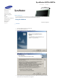
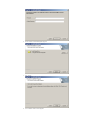
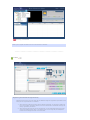
1.
Insert the installation CD into the CD-ROM drive.
2.
Click the MagicNet installation file.
3.
When the InstallShield Wizard window appears, click "Next."
4.
Select "I agree to the terms of the license agreement" to accept the terms of use.
5.
You are required to log in to the MagicNet Server program. Please enter the password to login. The
password cannot be changed when you are logged in.
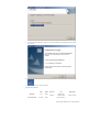
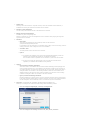
6.
Choose a folder to install the MagicNet program.
7.
Click "Install."
8.
The "Installation Status" window appears.
9.
It is recommended restarting the system for the normal operation of the MagicNet Server program.
Click "Finish."
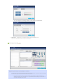
10.
When the installation is complete, the MagicNet executable icon appears on your desktop.
11.
Double-click the icon to start the program.
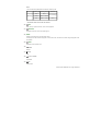
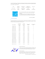
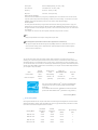
System Requirements
Minimum
Recommended
CPU
RAM
P1.8
256M
P3.0Ghz
512M
Ethernet
OS
100M/1G
Windows 2000
Application
Windows XP
WMP 9 or later
(Service Pack 4)
© 1995~2007 SAMSUNG. ALL Right Reserved
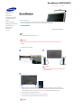
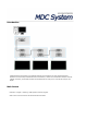
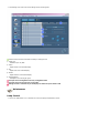
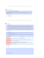
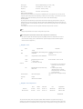
Introduction
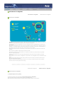
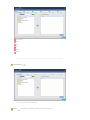
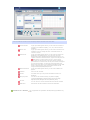
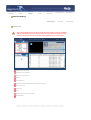
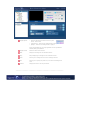
A Multiple Display Control (MDC) is an application allowing various displays to be easily and simultaneously
operated on a PC. RS-232C, a standard of serial communication, is used for the communication between a PC and
a display. Therefore, a serial cable should be connected between the serial port on a PC and the serial port on a
display.
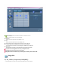
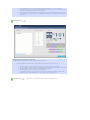
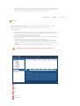
Main Screen
Click Start > Program > Samsung > MDC System to start the program.
Select a set to see the volume of the selected set within the slider.
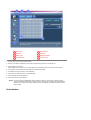
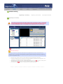
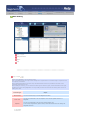
Main Icons
Select Button
Remocon
Info Grid
Safety Lock
Display Selection
Port Selection
Control Tools
1. Use the main icons to switch into each screen.
2. Allows you to enable or disable the remote control signal receiving function of the display unit.
3. Set the Safety Lock function.
When setting the Lock function, you can only operate power and lock buttons on the remote control and set.
4. The setting for the PC Serial Port can change. The original value is COM1.
5. Click Select all or Clear to select or clear all displays.
6. Use Grid to view brief information on selected display.
7. Select a display from Display Selection.
8. Use Control Tools to control displays.
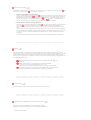
<Note> The remote control Enable/Disable function operates whether or not the power is On/Off, and this
applies to all displays connected to the MDC. However, regardless of the status at the time the MDC is
shut down, the remote control signal receiving function of all displays is initialized to Enable when the
MDC is closed.
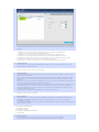
Port Selection
1. The Multiple Display Control is originally set to COM1.
2. If any port other than COM1 is used, COM1 through COM4 can be selected in the Port Selection Menu.
3. If the exact port name that is connected to the LCD Display using a serial cable is not selected, communication will
be unavailable.
4. The selected port is stored in the program and used for the next program as well.
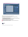
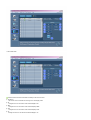
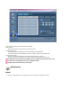
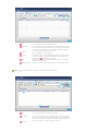
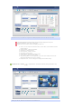
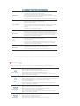
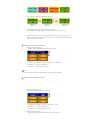
Power Control
1. Click Power Control of the main icons and the Power Control screen appears.
Info Grid shows some basic information necessary to Power Control.
1)
(Power Status)
2) Input
3) Image Size
4) On Timer
5) Off Timer
2. Use the Select All button or Check Box to choose a display to control.
Power Control allows controlling some of the functions of the selected display.
1) Power On/Off
- Turns the power of the selected display On/Off.
2) Volume
- Controls the volume level of the selected display.
It receives the volume value of the selected display from the sets and displays it in the slider.
(When you cancel the selection or choose Select All, the value returns to the default value 10)
3)
(Mute On/Off)
- Turns on/off the Mute function of the selected display.
When selecting one set at a time, turn on the Mute function for the selected set.
The Mute function is disabled automatically when you adjust the volume level.
(The values return to the default settings when you undo the selections or choose "Select All".)
The Power Control feature is available for all displays.
The Volume Control and Mute features are available only for the displays whose power status is ON.
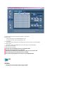
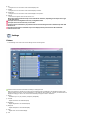
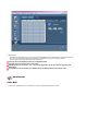
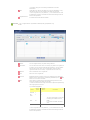
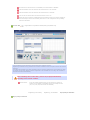
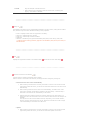
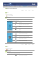
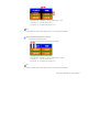
Input Source
1. Click Input Source of the main icons and the Input Source control screen appears.
Click Select All or use Check Box to select a display to control.
• TV Mode
• PC Mode
Info Grid shows some basic information necessary to Input Source Control.
1) PC
- Changes the Input Source of the selected display to PC.
2) BNC
- Changes the Input Source of the selected display to BNC.
3) DVI
- Changes the Input Source of the selected display to DVI.
4) TV
- Changes the Input Source of the selected display to TV.
5) AV
- Changes the Input Source of the selected display to AV.
6) S-Video
- Changes the Input Source of the selected display to S-Video.
7) Component
- Changes the Input Source of the selected display to Component.
8) MagicNet
- The Input source of MagicNet works only on MagicNet model.
9) Channel
- Channel arrow appears when the Input Source is TV.
TV Source can be selected only in products with TV and controlling channels is allowed only when
Input Source is TV.
The Input Source Control feature is available only for the displays whose power status is ON.
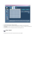
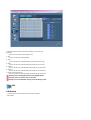
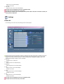
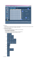
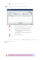
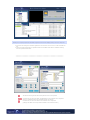
Image Size
PC, BNC, DVI
1. Click Image Size of the main icons and the Image Size control screen appears.
Info Grid shows some basic information necessary to Image Size Control.
1)
( Power Status)
- Shows the power status of the current display.
2) Image Size
- Shows the current Image Size of the display in use.
3) Input
- Shows the current Input Source of the display in use.
4) Info Grid displays only the displays whose Input Source is PC, BNC, DVI.
5) PC Source - When you click Image Size, the PC Source tab first appear.
- The Image Size Control button controls Image Size available for PC, BNC, DVI.
6) Video Source
- Click the Video Source tab to control Image Size for respective Input Source.
The Input source of MagicNet works only on MagicNet model.
The Input source of TV works only on TV model.
Image Size Control is available only for the displays for which power status is ON.
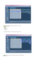
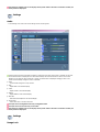
Image Size
TV, AV, S-Video, Component, DVI(HDCP)
1. Click Image Size of the main icons and the Image Size control screen appears.
Info Grid shows some basic information necessary to Image Size Control.
1) Click the Video Source tab to adjust Image Size for TV, AV, S-Video, Component. , DVI(HDCP).
Click Select All or use Check Box to select a display to control.
2) Info Grid displays only the display having TV, AV, S-Video, Component or DVI(HDCP) as input source.
3) Switch Image Size of the selected display randomly.
Note: Auto Wide, Zoom1 and Zoom2 are not available for selection when the input signal type for
Component and DVI (HDCP) is 720p or 1080i.
( The Auto Wide mode is available only for TV, AV, and S-Video. )
The Input source of MagicNet works only on MagicNet model.
The Input source of TV works only on TV model.
The Image Size Control feature is available only for the displays whose power status is ON.
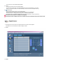
Time
1. Click Time of the main icons and the Time Control screen appears.
Info Grid shows some basic information necessary to Time Control.
1) Current Time
- Set the current time for the selected display (PC Time).
- To change the current time, first change the PC Time.
2) On Time Setup
- Set the Hour, Minute, AM/PM of On Time Setup, Status, Source, Volume of the selected display.
3) Off Time Setup
- Set the Hour, Minute, and AM/PM, Status for Off Time Setup of the selected display.
4) Shows the On Time settings.
5) Shows the Off Time settings.
The Input source of MagicNet works only on MagicNet model.
The Input source of TV works only on TV model.
Time Control is available only for the displays for which the power status is ON.
At On Time Setup, TV Source functions only for TV Model.
At On Time Setup, MagicNet Source functions only for MagicNet Model.
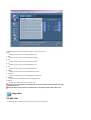
PIP
PIP Size
1. Click PIP of the main icons and the PIP control screen appears.
Click Select All or use Check Box to select a display to control.
Info Grid shows some basic information necessary to PIP Size Control.
1) PIP Size
- Shows the current PIP Size of the display in use.
2) OFF
- Turns off the PIP of the selected display.
3) Large
- Turns on the PIP of the selected display and changes the size to Large.
4) Small
- Turns on the PIP of the selected display and changes the size to Small.
5) Double 1
- Turns on the PIP of the selected display and changes the size to Double 1.
6) Double 2
- Turns on the PIP of the selected display and changes the size to Double 2.
7) Double 3 (Picture By Picture)
- Turns on the PBP of the selected display and changes the size to Double 3.
The Input source of MagicNet works only on MagicNet model.
The Input source of TV works only on TV model.
PIP Size can be controlled with turning on the LCD Display power.
PIP
PIP Source
1. Click PIP of the main icons and the PIP control screen appears.
• PIP TV Mode
• PIP S-Video Mode
Info Grid shows some basic information necessary to PIP Source Control.
1) PIP Source
- PIP Source can be controlled with turning on the LCD Display power.
2) PC
- Changes the source of the PIP of the selected display to PC.
3) BNC
- Changes the source of the PIP of the selected display to BNC.
4) DVI
- Changes the source of the PIP of the selected display to DVI.
5) TV
-Changes the source of the PIP of the selected display to TV.
6) AV
- Changes the source of the PIP of the selected display to AV.
7) S-Video
- Changes the source of the PIP of the selected display to S-Video.
8) Component
- Changes the source of the PIP of the selected display to Component.
9) Channel
- Channel arrow appears when the PIP Source is TV.
Note: Some of the PIP Sources may not be available for selection, depending on the input source type
of the Main Screen.
The Input source of MagicNet works only on MagicNet model.
The Input source of TV works only on TV model.
TV Source can be selected only in products with TV and controlling channels is allowed only when PIP
Source is TV.
The PIP Control feature is available only for the displays whose power status is ON and the PIP
function is set to ON.
Settings
Picture
1. Click Settings of the main icons and the Settings Control screen appears.
Info Grid shows some basic information necessary to Settings Control.
When each function is selected, the set value of the selected function is displayed in the slide.When selected, each
function fetches the value for the set and displays it on the slide bar. When "Select All" is chosen, the default value is
displayed. Changing a value in this screen will automatically change the mode to "CUSTOM."
1) Picture
- Available only for TV, AV, S-Video, Component, DVI(HDCP).
2) Contrast
- Adjusts Contrast of the selected display.
3) Brightness
- Adjusts Brightness of the selected display.
4) Sharpness
- Adjusts Sharpness of the selected display.
5) Color
- Adjusts Color of the selected display.
6) Tint
- Adjusts Tint of the selected display.
- Available only for NT.
7) Color Tone
- Adjusts the Color Tone for the selected display.
The Input source of MagicNet works only on MagicNet model.
The Input source of TV works only on TV model.
This feature is available only for the displays whose power status is ON and if no selection is made, the
factory default is displayed.
Settings
Picture PC
1. Click Settings of the main icons and the Settings Control screen appears.
Info Grid shows some basic information necessary to Settings Control. When each function is selected, the set value
of the selected function is displayed in the slide. When selected, each function fetches the value for the set and
displays it on the slide bar. When "Select All" is chosen, the default value is displayed. Changing a value in this
screen will automatically change the mode to "CUSTOM."
1) Picture PC
- Available only for PC, BNC, DVI.
2) Contrast
- Adjusts Contrast of the selected display.
3) Brightness
- Adjusts Brightness for the selected display.
4) Red
- Adjusts red Color of the selected display.
- Available only for NT.
5) Green
- Adjusts green Color of the selected display.
- Available only for NT.
6) Blue
- Adjusts blue Color of the selected display.
- Available only for NT.
The Input source of MagicNet works only on MagicNet model.
The Input source of TV works only on TV model.
This feature is available only for the displays whose power status is ON and if no selection is made, the
factory default is displayed.
Settings
Audio
1. Click Settings of the main icons and the Settings Control screen appears.
Info Grid shows some basic information necessary to Settings Control. When each function is selected, the set value
of the selected function is displayed in the slide. When selected, each function fetches the value for the set and
displays it on the slide bar. When "Select All" is chosen, the default value is displayed. Changing a value in this
screen will automatically change the mode to "CUSTOM."
1) Audio
- Controls audio settings for all input sources.
2) Bass
- Adjusts Bass of the selected display.
3) Treble
- Adjusts Treble of the selected display.
4) Balance
- Adjusts Balance of the selected display.
5) SRS TSXT
- SRS TSXT Sound ON/OFF of the selected display.
6) Sound Select
- Select either Main or Sub when PIP is On.
The Input source of MagicNet works only on MagicNet model.
The Input source of TV works only on TV model.
This feature is available only for the displays whose power status is ON and if no selection is made, the
factory default is displayed.
Settings
Image Lock
1. Click Settings of the main icons and the Settings Control screen appears.
Info Grid shows some basic information necessary to Settings Control.
1) Image Lock
- Available only for PC, BNC.
2) Coarse
- Adjusts Coarse of the selected display.
3) Fine
- Adjusts Fine of the selected display.
4) Position
- Adjusts Position of the selected display.
5) Auto Adjustment
- Self-Adjust to the incoming PC signal.
The Input source of MagicNet works only on MagicNet model.
The Input source of TV works only on TV model.
Settings Control is available only for the displays for which the power status is ON.
Maintenance
Lamp Control
1. Click on the "Maintenance" icon in the Main Icon column to display the Maintenance screen.
An "Info Grid" showing several basic data items appears.
1) Maintenance
- Allows the Maintenance Control function for all input sources.
2) Auto Lamp Control
- Automatically adjusts the backlight of the selected display at a specified time.
The Manual Lamp Control automatically turns off if you adjust using the Auto Lamp Control.
3) Manual Lamp Control
- Allows you to adjust the backlight of the selected display regardless of the time.
The Auto Lamp Control automatically turns off if you adjust using the Manual Lamp Control.
The Maintenance Control feature is available only for the displays whose power status is ON.
The Input source of MagicNet works only on MagicNet model.
The Input source of TV works only on TV model.
Maintenance
Scroll
1. Click on the "Maintenance" icon in the Main Icon column to display the Maintenance screen.
1) Safety Screen
- Eliminates the afterimages that can result when the selected display stays in Pause mode for an extended period of
time. You can set the repeat cycle timer by selecting the "Interval" by hour and "Second" by second.
It can be set to Scroll, Pixel, Bar and Eraser by Screen Type.
The Input source of MagicNet works only on MagicNet model.
The Input source of TV works only on TV model.
Setting Second, you can set to 1, 2, 3, 4, 5 for Scroll Type and to 10, 20, 30, 40, 50 for Pixel, Bar, and
Eraser Type.
The Maintenance Control feature is available only for the displays whose power status is ON.
Maintenance
Video Wall
1. Click on the "Maintenance" icon in the Main Icon column to display the Maintenance screen.
1) Video Wall
- A Video Wall is a set of video screens that are connected together, so that each screen shows a part of the whole
picture or so that the same picture is repeated on each screen.
2) Video Wall (Screen divider)
- The screen can be divided into.
You can select a number of screens with a different layout when dividing.
z
Select a mode from Screen divider.
z
Select a display from Display Selection.
z
The place will be set up by pressing a number in the selected mode.
z
The MDC program supplied by Samsung supports over 4*4.
z
2*2
z
3*3
z
4*4
z
1*2
z
2*1
z
1*5
z
5*1
3) On / Off
- Turns on/off the Video Wall function of the selected display.
4) Format
- The format can be selected to see a divided screen.
z
Full
z
Natural
You may not operate this function in MagicNet.
The Input source of TV works only on TV model.
The Maintenance Control function is available only for the displays where the power status is ON.
Troubleshooting
1. The display you wish to control does not appear on the Power Control Info Grid
- Check the connection of RS232C. (Check if it is properly connected to the Com1 port)
- Check the displays to see if any of the other displays connected have the same ID. If more than one displays have
the same ID, those displays are not properly detected by the program due to data conflict.
- Check if the Display Set ID is a number between 0 and 16 . (Adjust using the Display menu)
Note :
A Display Set ID must be a value between 0 and 16 .
2. The display you wish to control does not appear on the other Control Info Grids
- Check to see if the display power is ON. (You can check this in Power Control Info Grid)
- Check if you can change the input source of the display.
3. The dialogue box appears repeatedly.
- Check to see if the display you wish to control is selected.
4. Both On Timer and Off Timer have been set but different time is showing.
- Apply current time to synchronize the display clocks.
5. The remote may not function properly when you turn off the remote Function, disconnect the RS-232C cable, or exit
the program in an Irregular manner. Rerun the program and turn the remote function again to Restore normal
functions.
<Note> This program may malfunction due to problems in communication circuits or interference from electronic
appliances nearby.
Settings Value Display In Multiple Display Mode
When there are more than one displays connected, the settings values are displayed as follows.
1. No selection: Displays the Factory Default Value.
2. Selected one display: Fetches and displays the settings value for the selected display.
3. Selected one display (ID1) and add another display (ID3): The program, which was displaying the settings value of
ID 1, fetches and displays the value of ID3.
4. Selected all sets using Select All: Returns to the Factory Default Value.
Introduction
to MagicNet
|
Schedule
Setting
|
Function
Setting
|
Basic
Setting
|
Remote Control
| Troubleshooting |
Adjustment
Specifications
Introduction to MagicNet
Introduction to MagicNet
Added Functions in MagicNet
Introduction to MagicNet
MagicNet transmits media files (photo, audio and movie files) and office files existing on a server to
monitors using the Ethernet network of the server/client architecture.
Several monitors can be connected to a server, and any file can be transmitted to any monitor over
the network.
Files can be transmitted in two ways: the server sends files to the monitors after registering with the
schedule; or a monitor searches for the files registered in the library of the server, sends the files to
the monitors, and plays those files after receiving them via the network.
When more than one server is connected, you can select a server from the monitor and receive the
schedule.
Each monitor is capable of accessing the Internet by itself.
Servers and monitors are connected over the network, and each server and monitor has a proper
name to confirm each other.
Hence, the name of the server must be identical between the server and the clients for a normal
connection.
That is, when a server's name is "MagicNet", only monitors set to "MagicNet" can be connected to this
server.
When a server name does not exist under the name set in the monitor, it will wait until the server
with the identical name appears.
However, when the auto connection function is on, it will try to connect to other servers, and will
connect to the server that gives the first reply.
Introduction to MagicNet
Added Functions in MagicNet
Added Functions in MagicNet
1. Multiple Display Control (MDC)
The Multiple Display Control (MDC) is a newly added function in MagicNet,
which can easily control several monitors from a PC simultaneously.
MDC checks and controls the status of monitors that normally connect via the network.
2. Account Management
This function prevents a random user from freely using MagicNet, by placing limits on the operation of
functions according to the account privilege.
3. Update
You can update a monitor's MagicNet from the server.
However, this function only works when it is connected to a server/monitor with MagicNet Ver 2.0 or higher.
For SyncMaster 320PXn/400P(T)Xn/460PXn, see Add/Remove Programs.
4. Controlling Local Storage Devices/USB File Control of Monitors
You can copy or delete files to a monitor's local storage device or via USB connected to the monitor.
5. Schedule Pause
This function pauses the ongoing schedule in the monitor, and is useful in the event of urgently needing to
conduct other work.
Press the buttons in the order of [+100]-[8]-[2]-[4]-[ENTER] on the monitor with the remote control, and
the schedule will pause temporarily.
To resume the temporarily paused schedule, press the buttons in the order of [PRE-CH]-[8]-[2]-[4][ENTER]on the remote control.
Introduction
to MagicNet
|
Schedule
Setting
|
Function
Setting
|
Basic
Setting
|
Remote Control
| Troubleshooting |
Adjustment
Specifications
Schedule Setting
Registering to the Library
Registering / the Schedule
Export/Import Schedule
Registering to the Library
The server program's Power-On option works only if the monitor's power is completely
shut off. Please make sure not to use the Power-On option when the monitor is in the
process of shutting up since it can possibly cause systemetic error on the monitor.
Registering to the Library
What is the Library?
The library consists of a collection of files which can be played from a monitor connected to the
MagicNet program. SyncMaster 400Pn/460Pn, SyncMaster 320PXn/400P(T)Xn/460PXn, SyncMaster
711ND can only play files with the supported formats registered in the library. The library only accepts
files of the supported formats.
z
z
z
z
Press the "Reg. Library" button to select files that can be registered to the library.
It has been designed in such a way that only files playable by a monitor can be registered. The
selected files are analyzed and the result is displayed.
Files added to the library are first, automatically classified in the list ( ) as movie, audio, photo
and office files, and then they are further classified according to the file type.
The Fields window( )displays the registered files and their information.
My Computer
URL
NFS
FTP
Socket
Serial
1. My Computer
z
2. URL
You can register files in My Computer.
: Supportable for SyncMaster 320PXn/400P(T)Xn/460PXn only
3. NFS
URL
You can register URLs through the Internet.
Nick Name
You can name a nick name of a URL to be registered so that it can
be used for load and edit operation. (If you register with the same
nick name, the existing URL, which has been registered with the
nick name is replaced with the new one.)
Address
Set a URL address to be registered.
Connect
Connect to a URL using the registered nick name and URL Address.
If the connection is successfully established, Internal Explorer is
launched and ( ) Add button is activated.
Add
If the connection is successfully established, save the connection
information into the DB.
Display interval
Refresh the screen with the specified URL at each Display interval.
: Supportable for SyncMaster 320PXn/400P(T)Xn/460PXn only
NFS
You can register TEXT(.txt) data through NFS.
Nick Name
You can name the nick name of a custom data to be registered so
that it can be used for load and edit operation. (If you register with
the same nick name, the existing data, which has been registered
with the nick name, is replaced with the new one.)
Address
Set an address to be registered.
(You have to set the shared IP and folder name.)
4. FTP
Connect
Connect to NFS using the registered nick name and address. If the
connection is successfully established, the following ( ,
) Open
and Add buttons are activated.
Path
Shows a successfully connected NFS path.
Open
File Navigation window appears where you can select a file (TEXT
(.txt) data) using the successfully established connection
information.
Add
Load TEXT(.txt) data of the path set in the File Navigation, copy
the data to the server PC and save the data onto the DB.
=>In an original text (.txt) data file, "," and "LineFeed" are used
as delimeters between cells that are determined during the Multi
Screen edit operation.
Registered files
A window that shows DB information.
Edit
A window appears where you can set Raw data
Interval/Interval/Display interval for TEXT(.txt) data.
If you select multiple TEXT(.txt) data, only the first data of the list
is modified.
=> Raw data Interval : Time to load original TEXT(.txt) data file
into the buffer.
Interval : The time to create a file with the data loaded in the
buffer by separating the data into the number of columns and rows
set during the Multi Screen edit operation.
Display interval : The time to refresh the monitor screen.
Delete
Delete a selected TEXT(.txt) data among the registered TEXT(.txt)
data.
(Multiple selection by Shift or Ctrl key is supported for deletion)
: Supportable for SyncMaster 320PXn/400P(T)Xn/460PXn only
FTP
You can register TEXT(.txt) data through FTP.
Nick Name
You can name the nick name of a TEXT(.txt) data to be registered
so that it can be used for load and edit operation. (If you register
with the same nick name, the existing data, which has been
registered with the nick name, is replaced with the new one.)
Address
Set an address to be registered.
Connect
Connect to FTP using the registered nick name and address. A popup window appears where you can enter the ID and password for
the FTP. If the connection is successfully established, the following
( , ) Open and Add buttons are activated. ( ) Path : Shows the
path of the succefully connected FTP.
Path
Shows the path of the succefully connected FTP.
Open
File Navigation window appears where you can select a file (TEXT
(.txt) data) using the successfully established connection
information.
Add
Load TEXT(.txt) data of the path set in the File Navigation, copy
the data to the server PC and save the data onto the DB.
=>In an original text (.txt) data file, "," and "LineFeed" are used
as delimeters between cells that are determined during the Multi
Screen edit operation.
Registered files
A window that shows DB information.
5. Socket
: Supportable for SyncMaster 320PXn/400P(T)Xn/460PXn only
Socket
You can register TEXT(.txt) data through Socket.
Nick Name
You can name the nick name of a TEXT(.txt) data to be registered
so that it can be used for load and edit operation. (If you register
with the same nick name, the existing data, which has been
registered with the nick name, is replaced with the new one.)
Address
Set an IP address to be registered.
Port
Set a Port to be registered.
Connect
Establish Socket connection using the registered nick name and
address. If the connection is successfully established, the ( ) Add
button on the side is activated.
Add
Copy TEXT(.txt) data that is transmitted through socket to the
server PC and save the data onto the DB.
=>Data is transferred through the Socket as packets separated by
the length prefixed scheme.
ex) CX12abcdefghabcd
Size in
bytes
Name
Default
Value
Protocol 1
C
Op
code
X
1
Size
16
Data
Varies
Comment
The size of message in bytes not
including the header and size
fields.
It is written in ASCII character
code.
=>In an original text (.txt) data file, "," and "LineFeed" are used
as delimeters between cells that are determined during the Multi
Screen edit operation.
Registered files
6. Serial
A window that shows DB information.
: Supportable for SyncMaster 320PXn/400P(T)Xn/460PXn only
Serial
You can register TEXT(.txt) data through Serial.
Nick Name
You can name the nick name of a TEXT(.txt) data to be registered
so that it can be used for load and edit operation. (If you register
with the same nick name, the existing data, which has been
registered with the nick name, is replaced with the new one.)
Add
You can open a connection via serial cable using the connection
information given below and save data to a database.
=>Data is transferred via the Serial as packets separated by EOF.
ex) 12345EOFcjojzpoEOF
=>In an original text (.txt) data file, "," and "LineFeed" are used
as delimeters between cells that are determined during the Multi
Screen edit operation.
Port
Set a Port to be registered.
Registered files
A window that shows DB information.
Registering to the Library
Registering / the Schedule
Export/Import Schedule
Registering / the Schedule
The server program's Power-On option works only if the monitor's power is completely
shut off. Please make sure not to use the Power-On option when the monitor is in the
process of shutting up since it can possibly cause systemetic error on the monitor.
Registering / the Schedule
Allows you to register the files to be run on the monitor in advance.
1. Library
Registering the schedule through the library
Among the files on the server PC, files that are added through the registration procedures in the
library can be registered with the schedule.
1. When selecting a file from among the files already registered, or selecting a random file
from the schedule registration window, the file is selected as a schedule file through the
library registration procedures.
2. When selecting an image file for the schedule file, you can add background music from
among the following music files. If a schedule file is not an image file, the add/delete
button for the background music is not activated.
1. Monitor List
Selecting either all monitors or a specific monitor, where the schedule will be added to, is
available from among the monitors connected via the network.
2. Schedule a File Add/Delete
You can select, add or delete the file to be added to the schedule.
3. Background Music Add/Delete
Available only when using image files.
Selects an audio file to use as the background music in advance when playing an image file
registered to the schedule.
4. Schedule
{ Start Time
This means the starting time of a schedule, which can be entered in
years/months/days/hours/minutes.
It is possible to set the start time of a schedule within 7 days of the current day, however
setting a time later than 7 days from now is not available.
{
Total Run Time
The total period of time reserved in the schedule.
{
Option
In repeating the schedule at an interval of a Daily/Weekly/Monthly, select the
interval to be repeated and the date for completing the repeat.
The end date of such a repetition can be set within 1 year of the current date.
If you do not select the repeat option or do not select the end date of the
repetition, the schedule will be added once by default.
5. Options
{ Insert between Existing Schedules
This means that a new schedule will be inserted without affecting the total playing time
of the existing schedules. If a new schedule to be inserted, intrudes on the end time of
an existing schedule, the start time selected by the user is ignored, and the start time is
changed to after the end time of the existing schedule. When the new schedule to be
added intrudes on the start time of an existing schedule, the start time of the existing
schedule is changed to after the end time of the new schedule.
{
Ignore/Overwrite Existing Schedules
Existing schedules are ignored, and a new user schedule overwrites at the required time.
If the new schedule overlaps with an existing schedule, the time of the existing schedule
can be changed or even be deleted, since it is overwritten by the new schedule.
6. AV Option : Supportable for SyncMaster 320PXn/400P(T)Xn/460PXn only
Allows you to configure the video and sound settings while scheduling content.
{
You can configure MagicBright, contrast, and brightness.
{
You can configure the settings of Color Tone, Red, Green, and Blue.
{
You can configure the settings of Bass, Treble, Balance, and SRS TSXT.
7. Slide Show : Supportable for SyncMaster 320PXn/400P(T)Xn/460PXn only
Determines the slide transition interval for Slide Show.
2. Storage (Local/USB)
Registering the Storage (Local/USB) File Schedule
You can select a file from among the local storage of the monitor, or from the USB connected to
the monitor to register the selected file with the schedule.
1. From the monitor list, select a monitor where the schedule is to be registered. The
add/delete button of the schedule file is only activated when selecting a monitor that is
currently connected to the server.
2. You can add a file from the local storage device of the monitor, or from the USB
connected to the monitor by pressing the add button. In this case, it will not go through
the library registration procedures on the server.
3. When selecting an image file for the schedule file, you can add background music. When
a schedule file is not an image file, the add/delete button for the background music is not
activated.
3. Input/Power
Registering the Input/Power Schedule
: Supportable for SyncMaster 400TXn only when the Source is TV.
You can register the input source or Power Off for the monitor with the schedule.
1. You can schedule a change of the output source or the power for the monitor.
2. After selecting a monitor where the schedule is to be registered in the monitor list, select
an input source or Power Off from the Input/Power Selection.
3. Set the schedule time and press the confirm button.
It will change into the registered output source at the start of the schedule, and it will
correctly return to the MagicNet Menu screen when the schedule is over.
4. Multi Screen
: Supportable for SyncMaster 320PXn/400P(T)Xn/460PXn only
You can divide the monitor screen to display multiple contents at the same time.
Screen Partition
A pop-up window appears where you can select the number of
screens to be divided for display. (1x1, 2x1, 1x2 and 2x2 are
available)
Monitor List
A pop-up window appears where you can select a monitor to be
scheduled. You can change the order of selected monitor or
remove a monitor.
Selected File
A pop-up window appears where you can select contents to be
displayed on the divided screen. You can select one from
Movie,Music,Image,URL,NFS,FTP,Socket,Serial and Source. To
register contents to a divided screen, register one and press the
◀ ▶ buttons to select another screen or select a blank
screen from the side Preview screen and register contents. If
you double-click a content from the list, the content is displayed
on the Preview window. You cannnot select both Movie and
Music at the same time even for different dividied screens. BGM
option is actiavted only when the selected contents are all
Image and URL/NFS/FTP/Socket/Serial.
BackGround Music
A pop-up window appears where you can select a BGM to be
played.
Schedule
Set a time for schedule.
Preview
A window where you can preview scheduled screens to be
displayed.
TEXT(.txt) data
You can set the formats of TEXT(.txt) data for display.
(Font/Size/Width/Italic/Underline/Align Left/Center/Align
Right/Sort/Color/Background Color/Boundary Color)
File save
You can save the current schedule and load a saved schedule.
Slide Show
Determines the slide transition interval for Slide Show.
4. Multi Screen - Edit Data
: Supportable for SyncMaster 320PXn/400P(T)Xn/460PXn only
Preview the text (.txt) data item registered in NFS/FTP/Socket/Serial to edit each cell data.
Font/Size/Bold/Italic/Underline/Align Left/Center/Align Right/Text Color/Text
Background/Border Color can be configured.
Right-click in the Preview window to display the Edit List.
z
z
z
z
z
z
z
z
z
Undo : You can restore the Delete Column, Delete Row, Column Width and Row
Height settings.
Delete Column : Delete the Column.
Delete Row : Delete the Row.
Insert Column : Insert a column.
Insert Row : Insert a row.
Column Width : Change the Column Width.
Row Height : Change the Row Height.
Copy Screen/Paste : You can split the screen into more multiple screens and
paste edit information from one to another.
Display Interval : You can change the Display Interval time setting.
4. Multi Screen - Preview
: Supportable for SyncMaster 320PXn/400P(T)Xn/460PXn only
Editing the Sound, Channel and Screen Size for Multi Screen.
If audio for the selected screen is unavailable, the Sound button is disabled.
The Sound button when the audio of the selected screen is not selected.
The Sound button when the audio of the selected screen is selected.
You can set the channel when the selected screen is set to TV.
When the mouse pointer is located between the selected screens, the pointer changes to
the arrow shape. Click on the boundary and move it so as to adjust the size by holding
down the left button.
5. Video Wall
: Supportable for SyncMaster 320PXn/400P(T)Xn/460PXn only
You can display a single zoomed-in content item across multiple monitors.
Registering a schedule is only possible if the number of divided screens is equal to that of the selected
monitors.
The Video Wall schedule only starts operating if all the monitors registered for the schedule are ready
to operate. If more than half the monitors registered to the schedule are not ready, that schedule is
canceled and closed automatically.
When scheduling video in Video Wall , pictures may be played intermittently
depending on the network condition.
Screen Divider
A pop-up window appears where you can select the number of
screens so as to display a magnified content on multiple screens.
(1x1, 2x2, 3x3, 4x4,1x5 and 5x1 are avaiable)
Registering to the Library
Export/Import Schedule
Registering / the Schedule
Export/Import Schedule
Allows you to import/export the schedules registered on the LCD display from/to a server computer.
z
z
A function for saving the schedule registered in the monitor to the server as a file and load the
file.
Save the schedule between the specified start and end dates and load the schedule starting
from the specified start date.
The list for defining the file name and path of a file to be exported.
,
A Combo Box to select the Start and End dates for the schedule to be exported.
(Only the schedules within the specified periods are saved.)
A Combo Box to select the date for the schedule to be imported.
(Changes the date for the imported schedules to the reference date.)
Introduction
to MagicNet
|
Schedule
Setting
|
Function
Setting
|
Basic
Setting
|
Remote Control
| Troubleshooting |
Adjustment
Specifications
Function Setting
Schedule OSD
MDC OSD
Message OSD
Schedule OSD
The server program's Power-On option works only if the monitor's power is completely
shut off. Please make sure not to use the Power-On option when the monitor is in the
process of shutting up since it can possibly cause systemetic error on the monitor.
Registering to the Library
Registering / the Schedule
Monitor Preview Window
Network
File Information
MagicNet/Network On/Off Status or Image Selection Menu
Play Control Tool
Library List
Date
Monitors connected via the Network
Fields Window
Monitor Preview Window
This window is used either to preview a file (a movie or photo file) registered in the library list (
selected in the fields window( ), or to monitor a monitor.
)and
1. Playing a file registered in the library
Click on a classification in the library list ( ), and the files under the selected classification are
displayed in the fields window ( ). Then, double-click on a file in the fields window to play it.
While playing, the file information is displayed in
Only audio, movie, and image files can be
played. For office files, only file information is displayed in
. However, if monitoring for a
monitor is proceeding, the information being monitored is displayed instead.
2. Monitoring the selected monitor (Preview)
With the relevant monitor selected by a number
(the name of the monitor will be displayed
in the field
), the screen played by the currently-selected monitor will be displayed.
Audio, video and image files can be played, while only the file information appears for office
files.
(In this case, only files registered in the library of the server will be played, and the local/USB
files on the monitor will display only the basic information. In addition, when the output source
of a monitor does not belong to MagicNet, information on the relevant output source will be
displayed.)
For Multi Screen and Video Wall, the filename of the project being played back is displayed.
Network
The status bar next to the monitor name will display the overall network status (traffic) of all the
monitors connected to the server. For example, assume that the network system capability is 100Mbs
and a 100Mbs network card is installed in the server. If there is no network traffic used for other
purposes, three monitors are connected, and each monitor uses 10Mbs of traffic, the progression will
be indicated as about 30%.
Server PC Environment: Recommended (CPU: 3GHz, RAM:512M, Ethernet:
100M/1G)
Network Environment: Local network not connected externally
- Normal: Server PC network bandwidth: 50% ~ 60%
- Max: Server PC network bandwidth: 90% or more (not recommended)
For a LAN-connected environment, the connectable number of devices may
be reduced depending on the availability of neighboring networks.
File Information
This will display the name, date, size and resolution of the current file.
MagicNet/Network On/Off Status or Image Selection Menu
Displays the On and Off status for the power and the network.
Selecting an image file will change to the appropriate image menu.
Extended Image Menu
z
Slide Show
z
z
z
z
Prv (Previous)
z
z
z
Nxt (Next)
z
z
Stop
z
z
When the files are selected in the library list :
Sequentially displays the image files registered to the library.
When monitoring information is being played from a schedule : Displays
the image files registered to the schedule.
When monitoring the information which the monitor user is selecting
and playing : This function is disabled.
When the files are selected in the library list :
Displays the previous file.
When monitoring information is being played from a schedule : Displays
the previous file. If a slide show is in progress, the slide show is
stopped.
When monitoring the information which the monitor user is selecting
and playing : This function is disabled.
When the files are selected in the library list : Displays the next file.
When monitoring information is being played from a schedule : Displays
the next file. If a slide show is in progress, the slide show is stopped.
When monitoring the information which the monitor user is selecting
and playing : This function is disabled.
When the files are selected in the library list :
Stops the slide show.
When monitoring information is being played from a schedule : Stops
the slide show.
When monitoring the information which the monitor user is selecting
and playing : This function is disabled.
Enlarges/shrinks an image file to fit to the full screen.
Double-click the screen to return to the original image size.
Full Screen
Play Control Tool
Controls for play, stop, next file, previous file, and volume when playing a movie or audio file.
z
z
Play / Pause
z
z
z
Stop
z
z
z
Previous/Next
z
z
first/last 5
z
When the files are selected in the library list :
Plays the audio/movie files registered with the library list.
When monitoring information is being played from a schedule :
Plays the audio/movie files registered with the schedule.
When monitoring the information which the monitor user is selecting and
playing : This function is disabled.
When the files are selected in the library list : Stops playing an audio/movie file.
When monitoring information is being played from a schedule :
This function is disabled.
When monitoring the information which the monitor user is selecting and
playing : This function is disabled.
When the files are selected in the library list :
Plays the previous/next file in the library list.
When monitoring information is being played from a schedule :
Plays the previous/next file in the schedule list.
When monitoring the information which the monitor user is selecting and
playing : This function is disabled.
When the files are selected in the library list :
Plays the first/last 5 seconds of the file.
When monitoring information is being played from a schedule :
seconds
z
Plays the first/last 5 seconds of the file.
When monitoring the information which the monitor user is selecting and
playing : This function is disabled.
Library List
Files added to the library are first, automatically classified in the list as movie, audio, photo and office
files, and then they are further classified according to their properties.
z
z
z
z
z
All file : Displays all files which are registered in the library.
Video File : Classified by actor (actress)
Music File : Classified by musician and album
Image File
Office file : Classified by file type Power MS Office(Word, Excel, Power Point), HTML, PDF
* Install the proper viewing (freeware) program to see MS Office (Word, Excel, Power Point) or
PDF documents.
Date
Displays the registered schedules in the Fields window (
) whose date are later than today (
).
Monitors Connected via the Network
Lists the names of monitors registered via the network.
When a monitor is connected to the network, its background color changes to yellow-green.
z
Reconnect to the other server automatically
1. When selecting a monitor that is currently connected to a server in the monitor list and
right-clicking it with the mouse, you can see an item titled 'Reconnect to the other server
automatically'.
2. When selecting 'Reconnect to the other server automatically', the field in front of the
menu item is marked, and will also be marked in the option Setup → Network Setup →
Reconnect to the other server automatically' in the monitor.
3. Selecting this menu enables a monitor to search for another server and connect to a
found server when the connection to the server with the name defined in the Setup is not
available.
Let's say there are two servers called S1 and S2, respectively, and a monitor called C,
which is currently connected to the S1 server. When the connection to S1 fails or stops,
C will automatically be connected to the S2 server.
z
Update
1. When selecting a monitor that is currently connected to a server in the monitor list and
right-clicking it with the mouse, you can see an item titled 'Update' in the menu.
This item enables you to update MagicNet (File name: NK.bin) on the monitor.
2. This item will be deactivated in monitors that are not connected to a server.
3. If you select the Update item, a window pops up. Search for the path to NK.bin, select it,
and click the Update button.
The update will proceed in two steps: Download (Save the update file in the monitor) →
Update (MagicNet installation)
4. You may cancel this function during the download stage, but not during the update
stage.
5. Once the update is completed, the monitor will reboot automatically.
6. If you try updating with an abnormal file, a warning message will appear, and the update
will not proceed.
7. Please make sure that the power of the monitor is not turned off while updating once the
download is over.
Furthermore, if the output source is a PC, please turn off the 'monitor off' function in the
power options of the connected PC for the duration of the update.
MagicNet is not operating normally.
If the power turns off during the update, contact our After-Sales Service Center.
8. For the SyncMaster 320PXn/400P(T)Xn/460PXn, see Add/Remove Programs.
z
Schedule Check
1. Select All Monitors:
Checks on all schedules of the registered monitors are available in the ( ) field. Rightclicking the mouse can turn the power ON or OFF as well as deleting the field. In
addition, you can change the name of the monitors.
The server program's Power-On option works only if the
monitor's power is completely shut off. Please make sure not
to use the Power-On option when the monitor is in the
process of shutting up since it can possibly cause systemetic
error on the monitor.
2. Select Monitor :
The schedules of the relevant monitor is queued.
z
Rename
Type a new name and click confirm. The new name will be saved.
Fields Window
Displays the status of a file.
z
z
z
When selecting All Monitors in the Schedule, you can view all schedules registered for each
monitor.
Control the time by double-clicking on a schedule.
When a monitor is selected in the monitor list. Displays the file name including the path,
category, start time, end time and playtime.
1. When the All Monitors entry is clicked in the monitor list ( ), schedules are not displayed in a
list, but with images of a box type. The schedules for all monitors in the monitor list are
displayed here. You can control the time by double clicking on a box type schedule, dragging
and dropping a schedule to move it to a different position, and cut, delete and paste a schedule
by using the menus displayed when the right mouse button is clicked.
For Video Wall, a schedule can only be moved up or down.
2. When you click on a monitor in the monitor list ( ), the schedules for that monitor are
displayed in the list. Right-clicking on a schedule list displays a context menu, allowing you to
copy, delete, or edit it. By using the Edit menu, you can change the selected file and time. By
using the Copy menu, you can select a monitor to copy.
For Multi Screen, when editing a schedule while it is running, you can only change the
information for the edited part.
3. The files registered to the library are displayed in a list. Right-clicking a file in the list displays a
menu, allowing you to view properties for a schedule and deleting a schedule, depending on the
kind of menu. You can also directly insert the selected file into a schedule.
Schedule OSD
MDC OSD
MDC OSD
Multiple Display Control (MDC) is a function for easily controlling several monitors from a PC.
MDC checks and controls the status of monitors that normally connect via the network.
How to Control
1. When selecting MDC from the monitor list window, the monitoring window and the schedule
window change into a window showing the monitor status and the control window, respectively.
2. First, select the monitor to apply in the client list window.
3. If you choose All Monitors, all monitors will be selected.
4. If you try to run the detailed functions for each tab without first selecting a monitor, a warning
message will appear.
5. After selecting a monitor, click each MDC tab to run the detailed functions.
In this case, when running menus that cannot be adjusted in the output source, the warning
'Adjustment unavailable' will appear. Furthermore, when running adjustable menus, the
selected values will be applied to the monitor, and the results will be applied to the MDC status
window.
If not applied to the monitor, it will also not be applied to the MDC status window.
The MDC functions comply with the specifications for running the monitor.
Power
Source
Image
Time
PIP
Setting
Maintenanace
Message OSD
Power
Power - Select Power On/Off
z
z
On
Off
Channel - Channel - / +
z
z
+
Volume - When changing the volume, the changed details will appear in an OSD on the monitor
screen.
z
0 ~ 100
Source
In the source tab, the output source of the monitor can be changed.
When selecting the following output source, it will change to the relevant output source.
When the relevant device is not connected, a screen with 'Connection required' will appear.
z
z
z
z
z
z
z
z
PC
BNC
DVI
AV
S-Video
Component
MagicNet
TV : Supportable for SyncMaster 400TXn only
Image
Picture
You can adjust the Screen from TV/AV sources other than PC.
z
Picture Mode : Dynamic, Standard, Movie, Custom
z
Custom :
z
Color Tone :
Cool2 , Cool1, Normal, Warm1, Warm2
z
Size :
Auto Wide, 16:9, Zoom1, Zoom2, 4:3
z
The others :
Digital NR On/Off, Film Mode On/Off
Contrast, Brightness, Sharpness, Color, Tint
Picture PC
Adjusts the Screen of a PC.
z
MagicBright : Entertain, Internet, Text, Custom, Contrast, Brightness
z
Color Tone : Cool, Normal, Warm, Custom, Red, Green, Blue
z
Size :
16:9, 4:3
Time
Current Time
Establishes the standard time of the monitor.
In Hours, Minutes and AM/PM, select the time, and click the Apply button.
The current standard time of the monitor will be set.
To activate the On/Off Timer at the set time, the Current Time must be set.
z
z
z
Hour
Minute
am/pm
On Timer
Select the time, output source and volume, and click the Apply button. The monitor will turn on with
the established source and volume at the established time.
When Activated is OFF, the ON Timer will not work
z
z
z
z
z
z
Hour
Minute
am/pm
Activated
Source
Volume
Off Timer
Select the time and click the Apply button. The monitor will turn off at the set time.
When Activated is OFF, the Off Timer will not work.
z
z
z
z
Hour
Minute
am/pm
Activated
PIP
Size
Select a size. (The size selection has an 'ON' function)
z
z
z
z
z
z
Off
Large
Small
Double1
Double2
Double3
Source
When selecting sources to be output to PIP, the relevant source will be applied to PIP.
When trying to change a source where PIP cannot be applied or the combination of Main/Sub is
incompatible, a warning message will appear on the monitor.
z
z
z
PC
BNC
DVI
z
z
z
z
AV
S-Video
Component
TV : Supportable for SyncMaster 400TXn only
Position
Select a position.
z
z
z
z
z
(LeftTop)
(RightTop)
(LeftBot)
(RightBot)
Swap
Setting
1. Sound Mode
z
z
z
z
z
z
Standard
Music
Movie
Speech
Custom
Bass, Treble, Balance
2. Sound Option
z
z
SRS TSXT ON/OFF
Sound Select Main/Sub
3. Image Lock
z
z
z
z
Coarse -/+
Fine -/+
Position
Auto Adjustment
4. Siganal Balance
z
z
z
z
z
z
Signal Balance ON/OFF
Phase R : 0 ~ 100
Phase G : 0 ~ 100
Phase B : 0 ~ 100
Gain : 0 ~ 100
Sharpness : 0 ~ 100
Maintenanace
Lamp Control
You can control the intensity of the lamp.
(Auto/Manual is available. When Auto is running, Manual is off; and when Manual is running, Auto is
off.) In Auto mode, the lamp is adjusted to the previously set value at the set time. In Manual, the
previous value is maintained.
z
Auto - Hour, Minute, am/pm, Value
z
Manual - 0 ~ 100
Safety Screen
The Safety Screen function is used to prevent afterimages that may appear when a still picture is
displayed on the screen over a long time.
- The Screen Scroll function scrolls the screen for the specified period of time.
- This function is not available when the power is turned off.
z
z
z
Interval
Second
Type
Video Wall
This offers a function that enables you to use several monitors as one screen.
First, select the button that sets the number of monitors to be used and their allocation. The allocation
figure will appear as a selectable button on the side.
For example, when you choose 2*2, selectable buttons in the form of 2 rows and 2 lines appear, and if
you select number 3 in this matrix, the third screen of the output screen divided by 4 will show up in
the monitor.
- The MDC program supplied by Samsung supports over 4*4.
z
z
z
z
z
z
z
z
z
1*2
2*1
2*2
3*3
4*4
1*5
5*1
OFF
Format - Full, Natural
Safety Lock
z
Safety Lock ON/OFF
Schedule OSD
MDC OSD
Message OSD
When entering a message to the server and setting the options needed before sending it, the message
is displayed on the selected client monitor.
Unavailable while the source is being displayed.
The Transparent Ticker is only available when the client is in Landscape mode.
Message OSD
Display Option
z
Normal: Outputs fixed sentences one by one.
Scroll : Text scrolls.
z
z
Trancparency : Sets the text background to transparent.
Opaque : Sets the text background to opaque.
Scroll and transparency are only applicable for the SyncMaster
320PXn/400P(T)Xn/460PXn.
Display Period
Marked in hours and minutes.
Start
Displays a message on the selected monitor.
Stop
Stops displaying a message on the selected monitor.
Clear
Allows you to change the text in the message edit box.
Font
Allows you to specify the point size, text color and background
color.
Position
Displays the text at the top or bottom.
Introduction
to MagicNet
|
Schedule
Setting
|
Function
Setting
|
Basic
Setting
|
Remote Control
| Troubleshooting |
Adjustment
Specifications
Basic Setting
Login / Logout
Change Password
Option
Help
Login / Logout
Before using MagicNet, you first need to login.
After a successful login, the Login button changes to a Logout button. A successful login is required to use
the majority of functions.
When installing MagicNet for the first time, the administrator account is provided on the basis of the
password entered by the user.
When adding an account, you can select from among three account types, and the selected account type
decides the scope of using MagicNet. You may modify or delete the accounts of existing users as well as
adding new users.
Account Type
Administrator
Power User
Operator
z
z
User Name
Password
Scope
You have the authority to use all MagicNet functions.
You are not authorized to use the Options menu and the Update function of
MagicNet.
You are not authorized to use the right mouse button click
in the Library Registration, Options menu, MDC and Monitor List from among the
MagicNet functions.
Change Password
You can change your password in the login status.
Enter your password correctly before logging in.
You will be prompted to enter the password for installing MagicNet, and this password will become the
default password for the administrator account. If you forget the password, please remove the
program and re-install it.
z
z
z
Old Password
New Password
Confirm Password
Option
1. Server Name
In the Options, you can specify the server name for the connection information. The servers and
monitors are connected via the network, and have proper names to identify each other. For a normal
connection, the server name between a server and monitor must match. In other words, when the
name of a server is MagicNet, only monitors whose server names are set to "MagicNet" can be
connected to that server and receive the schedule. When there is no server with that name set in the
monitor, it will wait until a server that matches this name appears. However, when the auto connction
function is ON, it tries to connect to any server, and will connect to the server that replies first.
z
Server Name
2. User Account
When installing MagicNet for the first time, the administrator account is provided on the basis of the
password entered by the user.
When adding an account, select from among three account types, and the selected account type
decides the scope of using MagicNet. You may modify or delete the accounts of existing users as well
as adding new users.
Account Type
Administrator
Power User
Operator
z
z
z
Scope
You have the authority to use all functions of MagicNet.
You are not authorized to use the Options menu and the Update function from
among the MagicNet functions
You are not authorized to use the right mouse button click
in the Library Registration, Options menu, MDC and Monitor List from among the
MagicNet functions.
Create
Modify
Delete
3. File Download
If the monitor is turned off at the scheduled download time, the system tries to turn on the monitor
and starts the download if the monitor is turned on within 3 minutes. Otherwise, the download will be
canceled.
1) Displays a list of the settings for downloading files to the monitor or deleting files.
(Displays the list for the currently connected monitor.)
2) Allows you to set the time for downloading files to the monitor or deleting files.
3) Allows you to specify the device and folder to which the downloaded files are saved.
4) Allows you to select the files from a server computer you want to download to your monitor.
5) Allows you to select the files you want to delete from your monitor.
6) Allows you to confirm and change the current download and deletion file selections.
4. Network Device
You can select a network device connected to the monitor. This is useful, especially if there are
multiple devices running on the PC.
z
Select a network device connecting to a monitor.
5. Monitor Update
You can update multiple monitors at the same time. This is useful when needing to update multiple
monitors at the same time.
When selecting a file to update and the update utility file (NK.bin) and clicking Update, the update
process is done in two steps. Download (stores the update file on the monitor) → Update (installs
MagicNet).
When done, the monitor restarts automatically. If an error (wrong file) is detected during this process,
a warning message appears and the update process stops.
When the download is completed, make sure to keep the monitor turned on during the update. And, if
the output source is a PC, make sure the monitor-off function, if any, of the PC is not activated.
Otherwise MagicNet may not operate properly. If the monitor turns off during the update process,
contact our customer service.
For SyncMaster 320PXn/400P(T)Xn/460PXn, see Add/Remove Programs.
z
Choose a monitor and file to update.
6. Monitor Model
If the monitor to the server is changed to SyncMaster 460Pn/400Pn, SyncMaster 320PXn/400P(T)
Xn/460PXn, SyncMaster 711ND or an integral model (mixed type), the server will be adjusted
according to the model.
Note that the supportable file formats, MDC and message-related functions will vary depending on the
selected monitor model.
z
z
z
z
z
SyncMaster 400Pn/460Pn
SyncMaster 711ND
SyncMaster 400TXn
SyncMaster 320PXn/400PXn/460PXn
Combination
7. Save Schedule
Allows you to save all the schedules registered on all monitors to a server database.
If you shutdown and run the server again, the saved schedules will be imported.
Help
1. Help
Runs program help.
2. About MagicNet
Indicates the program version and the copyright details.
Introduction
to MagicNet
Schedule
Setting
|
|
Function
Setting
|
Basic
Setting
|
Remote Control
| Troubleshooting |
Adjustment
Specifications
Remote Control Adjustment
PHOTO
MUSIC
MOVIE
OFFICE
PHOTO
Supported File Formats
Image File : JPG, BMP
Remote Control
z
When the files are selected in the library list
Previous file
Stop slideshow / View the bottom menu bar
Slideshow
Next file
z
When you see no menu in a zoomed-in picture
Move up to the top of the image
Move down to the bottom of the image
Move to the left of the image
Move to the right of the image
PHOTO
MUSIC
MUSIC
Supported File Formats
Music File : MP3
Remote Control
z
When the files are selected in the library list
File view on the cursor position /
MOVIE
OFFICE
Play / Pause during playback
Stop playing
Play in 5 seconds
Play 5 seconds earlier
Move to the previous file (when the cursor is
placed at the top, it will go back to the last file of
the previous page)
Move to the next file (when the cursor is placed at
the bottom, it will move to the first file of the next
page)
Move to the next page (when the current page is
the first, it will move to the next page)
Move to the previous page (when the current page
is the last, it will move to the previous page)
File view on the cursor position Play
PHOTO
MUSIC
MOVIE
OFFICE
MOVIE
Supported File Formats
Video File : MPEG1, WMV
Remote Control
z
When the files are selected in the library list
Move to the top (when the cursor is placed at the
top, it will go back to the last file of the previous
page)
Move to the bottom (when the cursor is placed at
the bottom, it will move to the first file of the next
page)
Move to the next page (when the current page is
the first, it will move to the next page)
Move to the previous page (when the current page
is the last, it will move to the previous page)
File view on the cursor position Play
z
Play
Play / Pause during playback
Stop playing
Play 5 seconds earlier
Play in 5 seconds
PHOTO
MUSIC
MOVIE
OFFICE
OFFICE
Supported File Formats
Office File : Power MS Office(Word, Excel, Power Point), HTML, PDF
* Install the proper viewing (freeware) program to see MS Office (Word, Excel, Power Point) or PDF
documents.
Remote Control
z
When the files are selected in the library list
Move to the top (when the cursor is placed at the
top, it will go back to the last file of the previous
page)
Move to the bottom (when the cursor is placed at
the bottom, it will move to the first file of the next
page)
Move to the next page (when the current page is
the first, it will move to the next page)
Move to the previous page (when the current page
is the last, it will move to the previous page)
File view on the cursor position
z
PDF
Move to the top
Move to the bottom
Move to the next page
Move to the previous page
Exit PDF
z
Excel
Move to the upper cell
Move to the lower cell
Move to the left cell
Move to the right cell
Move to the next page
Move to the previous page
Move to the left sheet
Move to the right sheet
Exit Excel
z
Power point Normal
Move to the top
Move to the previous page
Move to the next page
Move to the previous page
Slideshow
Exit Power point
z
Power point Slideshow
Stop slideshow
Move to the top
Move to the bottom
Move to the next page
Move to the previous page
Exit Power point
z
Word
Move to the top
Move to the bottom
Move to the next page
Move to the previous page
Exit Word
z
HTML
Move to the top
Move to the bottom
Move to the next page
Move to the previous page
Exit HTML
z
Internet
Move the mouse cursor up
Move the mouse cursor down
Move the mouse cursor to the left
Move the mouse cursor to the right
Click when the cursor is placed over a link (move
to the link)
Exit the Internet
Introduction
to MagicNet
|
Schedule
Setting
|
Function
Setting
|
Basic
Setting
|
Remote Control
|Troubleshooting|
Adjustment
Specifications
Troubleshooting
Troubleshooting
Removing Program
Troubleshooting
In Preview, the file information can be viewed but not the image
Office files are not displayed. Check the file for the format.
When there is no codec available for the server, no file is displayed. Check the codec
first.
MPEG2 and AC3 are played normally only when the server has the corresponding codec
available. Please install the corresponding codec.
Conflicts between codecs may occur when various kinds of codecs are installed on one
PC, which results in a program error. And the incomplete installation of a codec may
result in a program malfunction and file playback error.
In a Preview, the program does not operate
When you play a movie or music file in Preview, the player does not operate and stops
to check if the codec is available. Note that conflicts between codecs may occur when
various kinds of codecs are installed on one PC, which results in a program error. And
the incomplete installation of a codec may result in a program malfunction and file
playback error.
When a schedule does not run properly at the designated time:
Please check the status of MagicNet for the monitor and that of the network.
Furthermore, please confirm if the schedule pause function is activated for the monitor.
Schedules will only run when the status of MagicNet and the Network are ON, and will
not run when the monitor schedule is paused.
When the power goes off and returns or the network is disconnected and re-connected,
the current schedule returns to the start.
When the monitor icon is displayed in sky blue not green (normal operation):
This may occur when the network configuration is normal but the connection between
the server and the monitor is not functioning properly. This may occur when the monitor
is connected to another server, not the corresponding one, or the network status is not
normal.
Please check the monitor for the network connection.
Password/Login
The password entered by the user when installing MagicNet will become the default
password of the administrator account.
If you forget your password, please remove the program and install it again.
Troubleshooting
Removing Program
You can remove MagicNet by using the Add/Remove Options in Windows Programs
or by using the delete menu provided when installing this program.
To remove MagicNet, complete the following steps.
1. Select [Start]->[Settings]->[Control Panel].
Removing Program
2. For Windows XP, select [Start]->[Control Panel].
3. Double-click the [Add or Remove Programs] icon in the Control Panel.
4. Click the MagicNet in the [Add or Remove Programs] window to highlight it.
5. Click [Change/Remove] to remove it.
6. Click OK to start removal of MagicNet.
7. Wait until the window appears which indicates that program removal is completed.
Program updating via RDP is applicable for the SyncMaster 320PXn/400P(T)Xn/460PXn only.
1. Press the ALT + F12 keys to go to the Desktop.
2. For a remote connection (via the Remote Desktop Protocol), use the ID and password below.
Windows logon ID: Administrator
Windows logon password: 000000
Introduction
to MagicNet
|
Schedule
Setting
Function
Setting
|
Basic
Setting
|
|
Remote Control
| Troubleshooting | Specifications
Adjustment
Specifications
Supported File Format Spec
Audio
Bit rate
File Format
Resolution
CBR
Video
MPEG1
1280x720 or
less
WMV
Audio
Photo
Sampling
rate
VBR
Peak bitate
12Mbps or less
12Mbps or less
-
MP3
-
Available
Not Available
16kHz or
more
JPEG
2274 x 1704
or less
-
-
-
-
-
-
BMP
For JPEG, the EXIF Format (Digital Camera) is not supported.
(However, Samsung digital cameras are supported)
An Office file may take some time to be displayed on the monitor, depending on the file size.
For movies, only the WMV and MPEG1 codecs are provided by default.
You can install and use other needed codecs except for WMV and MPEG1. (Optional)
However, the compatibility of the codec may not be guaranteed depending on the codec.
Network Configuration (Number of Devices)
Video
Bit rate
Normal
Max
4Mbps
10
20
6Mbps
8
16
12Mbps
5
9
-
20 or more
-
Audio, Photo
Server PC Environment: Recommended (CPU: 3GHz, RAM:512M, Ethernet: 100M)
Network Environment: Local network not connected externally
Normal: Server PC network bandwidth: 50% ~ 60%
Max: Server PC network bandwidth: 90% or more (not recommended)
For a LAN-connected environment, the connectable number of devices may be reduced depending on
the availability of neighboring networks.
Server System Configuration
CPU
RAM
Minimum
P1.8Ghz
256M
Recommended
P3.0Ghz
512M
Ethernet
OS
Application
100M/1G
Windows XP
Windows 2000
(Service Pack 4)
WMP 9 or later
Local Device (USB) Connection Speed
For a mass storage device such as a USB hard disk, it takes approximately 3 - 4 seconds for loading 1 GB.
When the user operates MagicNet while the file is loading, a warning message is displayed.
Local Device (USB) compatibility
HID(Human Interface Devices)
: Keyboard, Mouse
MSC(Mass Storage Class)
: Devices using the SCSI(Small Computer System Interface) command set
Exception
: Some manufacturers have wrongly specified their device to be USB standard compatible.
Our product has exception handling procedures. But Some devices are unlikely to work properly.
: Some manufacturers have wrongly specified their device to be SCSI compatible.
Such devices are unlikely to work properly.
: It is recommended that USB devices are purchased after they are tested and confirmed to be compatible.
For pivoted monitors, video is supported up to the SD level.
SyncMaster 400PXn/460PXn
Select Language
Main Page
Model
Safety Instructions
Introduction
Connections
Using the Software
Adjusting the LCD Display
Input
Picture
[PC / BNC /DVI Mode]
Picture
[ AV / S-Video /
Component / DVI-Video
Mode]
Sound
Dodatak
Setup
Multi Control
Direct Functions
MagicNet
ǷȘȐȓȖȎȍȕȐȍ
The color and appearance of the product may vary depending on the model, and the product specifications are
subject to change without prior notice for reasons of performance enhancement.
Adjusting the LCD Display
Input
Troubleshooting
Specifications
Information
Appendix
Available Modes
PC / BNC / DVI
AV
S-Video
Component
DVI-Video
MagicNet
Source List
[MENU] → [ENTER] → [ENTER] → [∧ / ∨] → [ENTER]
Use to select PC, BNC, or other external input sources connected to the LCD Display.
Use to select the screen of your choice.
1) PC
2) BNC
3) DVI
4) AV
5) S-Video
6) Component
7) MagicNet
[The direct button on the remote control is the 'SOURCE' button. ]
Note
• PIP turns off when the LCD Display is switched to an external source.
PIP
When external A/V devices such as VCRs or DVDs are connected to the LCD Display , PIP allows you to watch
video from those devices in a small window super-imposed on the PC Video signal. (Off/On)
Note
• More than one PIP cannot be overlapped on screen as BNC and the component use the same terminal.
1) PIP
[MENU] → [ENTER] → [∧ / ∨] → [ENTER] → [ENTER] → [∧ / ∨] → [ENTER]
Turns the PIP Screen Off/On.
- Off
- On
[The direct button on the remote control is the 'PIP' button.]
2) Source
[MENU] → [ENTER] → [∧ / ∨] → [ENTER] → [∧ / ∨] → [ENTER] → [∧ / ∨] → [ENTER]
Selects the input source for the PIP.
- PC : AV / S-Video / Component Mode
- BNC : AV / S-Video Mode
- DVI : AV / S-Video / Component Mode
- AV / S-Video : PC / BNC / DVI Mode
- Component : PC / DVI Mode
[The direct button on the remote control is the 'SOURCE' button.]
3) Swap
[MENU] → [ENTER] → [∧ / ∨] → [ENTER] → [∧ / ∨] → [ENTER]
Swaps the contents of the PIP and main image.
The image in the PIP window will appear on the main screen, and the main screen image will appear in the
PIP window.
[The direct button on the remote control is the 'SWAP' button.]
4) Size
[MENU] → [ENTER] → [∧ / ∨] → [ENTER] → [∧ / ∨] → [ENTER] → [∧ / ∨] → [ENTER]
Changes the Size of the PIP window.
[The direct button on the remote control is the 'SIZE' button.]
5) Position
[MENU] → [ENTER] → [∧ / ∨] → [ENTER] → [∧ / ∨] → [ENTER] → [∧ / ∨] → [ENTER]
Changes the Position of the PIP window.
6) Transparency
[MENU] → [ENTER] → [∧ / ∨] → [ENTER] → [∧ / ∨] → [ENTER] → [∧ / ∨] → [ENTER]
Adjusts the Transparency of PIP windows.
- High
- Medium
- Low
- Opaque
Note
• If you select
,
,
in Size, Position and Transparency will not be activated.
Available Modes: PIP
Edit Name
[MENU] → [ENTER] → [∧ / ∨] → [ENTER] → [∧ / ∨] → [ENTER] → [∧ / ∨] → [ENTER]
Name the input device connected to the input jacks to make your input source selection easier.
1) PC
2) BNC
3) DVI
4) AV
5) S-Video
6) Component
Note
• MagicNet cannot be renamed.
Picture [PC / BNC / DVI Mode]
Available Modes
PC / BNC / DVI
AV
S-Video
Component
DVI-Video
MagicNet
MagicBright™
[MENU] → [∧ / ∨] → [ENTER] → [ENTER] → [∧ / ∨] → [ENTER]
MagicBright™ is a new feature providing the optimum viewing environment depending on the contents of the
image you are watching.
Currently four different modes are available: Entertain, Internet, Text and Custom.
Each mode has its own pre-configured brightness value. You can easily select one of the four settings by
simply pressing the MagicBright™ control button.
1) Entertain
High brightness
For watching motion pictures such as a DVD or VCD.
2) Internet
Medium brightness
For working with a mixture of images such as the text with graphics added.
3) Text
Normal brightness.
For documentations or work involving a lot of text.
4) Custom
Although the values are carefully chosen by our engineers, the pre-configured values may not be
comfortable for your eyes depending on your taste.
If this is the case, Adjusts the brightness and contrast by using the OSD menu.
[The direct button on the remote control is the 'M/B' button.]
Custom
[MENU] → [∧ / ∨] → [ENTER] → [∧ / ∨] → [ENTER] → [ENTER] → [∧ / ∨] / [< / >] → [ENTER]
By using the on-screen menus, the contrast and brightness can be changed to your personal preference.
1) Contrast
Adjusts the Contrast.
2) Brightness
Adjusts the Brightness.
Note
• By adjusting the picture using the Custom function, MagicBright will change to Custom mode.
Color Tone
[MENU] → [∧ / ∨] → [ENTER] → [∧ / ∨] → [ENTER] → [∧ / ∨] → [ENTER]
The color tones can be changed.
1) Cool
3) Normal
4) Warm
5) Custom
(Available in PC, BNC mode only)
Color Control
[MENU] → [∧ / ∨] → [ENTER] → [∧ / ∨] → [ENTER] → [ENTER] → [< / >] → [ENTER]
Adjusts the individual R, G, B color controls.
(Available in PC, BNC mode only)
1) Red
2) Green
3) Blue
Note
• If you adjust the picture by using the Custom function, Color Tone will turn to the Cusome mode.
Image Lock
Image Lock is used to fine-tune and get the best image by removing noise that creates unstable images with
jitters and shakiness. If satisfactory results are not obtained using the Fine adjustment, use the Coarse
adjustment and then use Fine again.
(Available in PC, BNC mode only)
1) Coarse
[MENU] → [∧ / ∨] → [ENTER] → [∧ / ∨] → [ENTER] → [ENTER] → [< / >] → [ENTER]
Removes noise such as vertical stripes. Coarse adjustment may move the screen image area. You may
relocate it to the center using the horizontal control menu.
2) Fine
[MENU] → [∧ / ∨] → [ENTER] → [∧ / ∨] → [ENTER] → [∧ / ∨] →[ENTER] → [< / >] → [ENTER]
Removes noise such as horizontal stripes. If the noise persists even after fine tuning, repeat it after
adjusting the frequency (clock speed).
3) Position
[MENU] → [∧ / ∨] → [ENTER] → [∧ / ∨] → [ENTER] → [∧ / ∨] →[ENTER] → [< / >] / [∧ / ∨]→
[ENTER]
Adjusts the screen location horizontally and vertically.
Auto Adjustment
[MENU] → [∧ / ∨] → [ENTER] → [∧ / ∨] → [ENTER]
The values of Fine, Coarse, Position are adjusted automatically.
By changing the resolution in the control panel, the auto function is performed.
(Available in PC, BNC mode only)
[The direct button on the remote control is the 'AUTO' button.]
Signal Balance
This is used to make up for the weak RGB signal transmitted by a long signal cable.
(Available in PC, BNC mode only)
1) Signal Balance
[MENU] → [∧ / ∨] → [ENTER] → [∧ / ∨] → [ENTER] → [ENTER] → [∧ / ∨] → [ENTER]
Selects either On or Off with the signal control.
2) Signal Control
[MENU] → [∧ / ∨] → [ENTER] → [∧ / ∨] → [ENTER] → [∧ / ∨] → [ENTER] → [∧ / ∨] → [ENTER] →
[∧ / ∨] → [< / >] → [ENTER]
Adjusts the R Phase, G Phase, B Phase, Gain and Sharpness manually.
Size
[MENU] → [∧ / ∨] → [ENTER] → [∧ / ∨] → [ENTER] → [∧ / ∨] → [ENTER]
The Size can be switched.
1) 16:9
2) 4:3
PIP Picture
[MENU] → [∧ / ∨] → [ENTER] → [∧ / ∨] → [ENTER] → [∧ / ∨] → [ENTER] → [∧ / ∨] → [ENTER] → [∧ /
∨] → [ENTER] → [< / >] → [ENTER]
Adjusts the PIP Screen Settings.
1) Contrast
Adjusts the Contrast of the PIP window on the screen.
2) Brightness
Adjusts the Brightness of the PIP window on the screen.
3) Sharpness
Adjusts the difference between the lightest and darkest areas of the PIP window.
4) Color
Adjusts the Color of the PIP window on the screen.
5) Tint
Adds a natural tone to the PIP window.
You can view a picture from AV, S-Video through the PIP screen in PC, BNC and DVI (PC) mode.
Operates only if the video signal is NTSC.
Available Modes: PIP
Picture [ AV / S-Video / Component / DVI-Video Mode]
Available Modes
PC / BNC / DVI
AV
S-Video
Component
DVI-Video
MagicNet
Mode
[MENU] → [∧ / ∨] → [ENTER] → [ENTER] → [∧ / ∨] → [ENTER]
The LCD Display has four automatic picture settings ("Dynamic", "Standard", "Movie" and "Custom") that are
preset at the factory.
Dynamic, Standard, Movie, or Custom can be activated.
1) Dynamic
2) Standard
3) Movie
4) Custom
[The direct button on the remote control is the 'P.MODE' button.]
Custom
[MENU] → [∧ / ∨] → [ENTER] → [∧ / ∨] → [ENTER] → [∧ / ∨] → [ENTER] → [< / >] → [ENTER]
By using the on-screen menus, the contrast and brightness can be changed to your personal preference.
1) Contrast
Adjusts the Contrast.
2) Brightness
Adjusts the Brightness.
3) Sharpness
Adjusts the picture sharpness.
4) Color
Adjusts the picture color.
5) Tint
Adds a natural tone to the display.
Operates only for AV and S-Video mode. Operates only if the video signal is NTSC.
Color Tone
[MENU] → [∧ / ∨] → [ENTER] → [∧ / ∨] → [ENTER] → [∧ / ∨] → [ENTER]
The color tones can be changed. The individual Color components are also user adjustable.
1) Cool 2
2) Cool 1
3) Normal
4) Warm1
5) Warm2
Size
[MENU] → [∧ / ∨] → [ENTER] → [∧ / ∨] → [ENTER] → [∧ / ∨] → [ENTER]
The Size can be switched.
1) Auto Wide
2) 16:9
3) Zoom 1
4) Zoom 2
5) 4:3
[The ZOOM1, ZOOM2 are not available in 1080i (or over 720p) of DTV.]
Digital NR (Digital Noise Reduction)
[MENU] → [∧ / ∨] → [ENTER] → [∧ / ∨] → [ENTER] → [∧ / ∨] → [ENTER]
Turns the Digital Noise Reduction feature Off/On.
The Digital Noise Reduction feature allows you to enjoy clearer and crisper images.
1) Off
2) On
Film Mode
[MENU] → [∧ / ∨] → [ENTER] → [∧ / ∨] → [ENTER] → [∧ / ∨] → [ENTER]
Turns Film Mode Off/On.
The Film Mode feature offers you a theater-quality viewing experience.
(Not available in DVI-Video Mode.)
1) Off
2) On
PIP Picture
[MENU] → [∧ / ∨] → [ENTER] → [∧ / ∨] → [ENTER] → [∧ / ∨] → [ENTER] → [∧ / ∨] → [ENTER] →[< / >]
→ [ENTER]
Adjusts the PIP Screen Settings.
1) Contrast
Adjusts the Contrast of the PIP window on the screen.
2) Brightness
Adjusts the Brightness of the PIP window on the screen.
Available Modes: PIP
Sound
Available Modes
PC / BNC / DVI
AV
S-Video
Component
DVI-Video
MagicNet
Mode
[MENU] → [∧ / ∨] → [ENTER] → [ENTER] → [∧ / ∨] → [ENTER]
The LCD Display has a built-in high fidelity stereo amplifier.
1) Standard
Selects Standard for the standard factory settings.
2) Music
Selects Music when watching music videos or concerts.
3) Movie
Selects Movie when viewing movies.
4) Speech
Selects Speech when watching a show that is mostly dialogue (i.e., news).
5) Custom
Selects Custom if you want to Adjusts the settings according to your personal preferences.
Custom
[MENU] → [∧ / ∨] → [ENTER] → [∧ / ∨] → [ENTER] → [∧ / ∨] → [ENTER] → [< / >] → [ENTER]
The sound settings can be adjusted to suit your your personal preferences.
1) Bass
Emphasizes low frequency audio.
2) Treble
Emphasizes high frequency audio.
3) Balance
Allows you to Adjusts the sound balance between the left and right speakers.
[You can hear the sound even when sound value is set to 0.]
Note
• If you adjust picture using Sound Custom function, Sound Mode will turn to Custom mode.
Auto Volume
[MENU] → [∧ / ∨] → [ENTER] → [∧ / ∨] → [ENTER] → [∧ / ∨] → [ENTER]
Reduces the difference in volume control between broadcasters.
1) Off
2) On
SRS TSXT
[MENU] → [∧ / ∨] → [ENTER] → [∧ / ∨] → [ENTER] → [∧ / ∨] → [ENTER]
SRS TSXT is a patented SRS technology that solves the problem of playing 5.1 multichannel content over two
speakers. TruSurround delivers a compelling, virtual surround sound experience through any two-speaker
playback system, including internal television speakers.
It is fully compatible with all multichannel formats.
1) Off
2) On
[The direct button on the remote control is the 'SRS' button.]
Sound Select
[MENU] → [∧ / ∨] → [ENTER] → [∧ / ∨] → [ENTER] → [∧ / ∨] → [ENTER]
Selects either Main or Sub when PIP is On.
1) Main
2) Sub
[Available Modes: PIP]
Setup
Available Modes
PC / BNC / DVI
AV
S-Video
Component
DVI-Video
MagicNet
Language
[MENU] → [∧ / ∨] → [ENTER] → [ENTER] → [∧ / ∨] → [ENTER]
You can choose from 11 languages.
Note
• The language chosen affects only the language of the OSD.
It has no effect on any software running on the computer.
Time
Selects from one of 4 time settings, Clock Set, Sleep Timer, On Timer, and Off Timer.
1) Clock Set
[MENU] → [∧ / ∨] → [ENTER] → [∧ / ∨] → [ENTER] → [ENTER] → [< / >] → [ENTER]
Current Time Setting.
2) Sleep Timer
[MENU] → [∧ / ∨] → [ENTER] → [∧ / ∨] → [ENTER] → [∧ / ∨] → [ENTER] →[< / >] → [∧ / ∨] →
[ENTER] →[< / >] → [∧ / ∨] → [ENTER]
Turns the LCD Display off automatically at certain times. (Off, 30, 60, 90, 120, 150, 180)
3) On Timer
[MENU] → [∧ / ∨] → [ENTER] → [∧ / ∨] → [ENTER] → [∧ / ∨] → [ENTER] → [< / >] → [∧ / ∨] →
[ENTER]
Turns the LCD Display on automatically at a preset time.
Controls the mode and the volume level at the time the LCD Display turns on automatically.
4) Off Timer
[MENU] → [∧ / ∨] → [ENTER] → [∧ / ∨] → [ENTER] → [∧ / ∨] → [ENTER] →[< / >] → [∧ / ∨] →
[ENTER]
Turns the LCD Display off automatically at a preset time.
Note
• When selecting Yes for the On Timer or Off Timer when the Clock is not set up, a guiding message pops
up: "Set the clock first.".
Menu Transparency
[MENU] → [∧ / ∨] → [ENTER] → [∧ / ∨] → [ENTER] → [∧ / ∨] → [ENTER]
Changes the opaqueness of the OSD background.
1) High
2) Medium
3) Low
4) Opaque
Safety Lock PIN
[MENU] → [∧ / ∨] → [ENTER] → [∧ / ∨] → [ENTER] → [0~9] → [0~9] → [0~9] → [0~9]
The password can be changed.
Energy Saving
[MENU] → [∧ / ∨] → [ENTER] → [∧ / ∨] → [ENTER] → [∧ / ∨] → [ENTER] → [MENU]
This feature adjusts the brightness of the LCD Display in order to reduce power consumption. When watching
LCD Display at night, set the "Energy Saving" mode option to "High" to reduce eye fatigue as well as power
consumption.
1) On
2) Off
Video Wall
A Video Wall is a set of video screens connected together, so that each screen shows a part of the whole
picture or where the same picture is repeated on each screen.
When the Video Wall is on, you can adjust the Video Wall screen setting.
1) Video Wall
[MENU] → [∧ / ∨] → [ENTER] → [∧ / ∨] → [ENTER] → [ENTER] → [∧ / ∨] → [ENTER]
Turns Off/On the Video Wall function of the selected display Off/On.
- Off
- On
2) Format
[MENU] → [∧ / ∨] → [ENTER] → [∧ / ∨] → [ENTER] → [∧ / ∨] →[ENTER] → [∧ / ∨] → [ENTER]
The format can be selected to see a divided screen.
- Full
Provides a full screen without any margins.
- Natural
Displays a natural image with the original aspect ratio intact.
3) Screen Divider
[MENU] → [∧ / ∨] → [ENTER] → [∧ / ∨] → [ENTER] → [∧ / ∨] → [ENTER] → [∧ / ∨] → [ENTER]
The screen can be divided into several images.
A number of screens can be selected with a different layout when dividing.
• Select a mode in Screen Divider.
• Select a display in Display Selection.
• The selection will be set up by pressing a number in the selected mode.
- 2x2
- 3x3
- 4x4
- 5x5
- 1x2
- 2x1
- 1x5
- 5x1
Note
• When Video Wall is running, the PIP, Auto Adjustment, Image Lock, and Size functions are not available.
Launching Video Wall while PIP is running, will switch PIP Off. Video Wall does not operate in MagicNet
mode.
Safety Screen
The Safety Screen function is used to prevent afterimages that may appear when a still picture is displayed on
the screen over a long time.
- The Screen Scroll function scrolls the screen for the specified period of time.
- This function is not available when the power is turned off.
1) Safety Screen
[MENU] → [∧ / ∨] → [ENTER] → [∧ / ∨] → [ENTER] → [ENTER] → [∧ / ∨] → [ENTER]
Determines whether to turn the Screen Scroll function Off or On.
- Off
- On
2) Interval
[MENU] → [∧ / ∨] → [ENTER] → [∧ / ∨] → [ENTER] → [∧ / ∨]→ [ENTER] →[∧ / ∨] → [ENTER]
Determines the time interval to run the Screen Scroll operation. (1~10 Hour)
The time is calculated on the basis of the power on time.
By default, the time is set to 10 hours.
- 1~10 Hour
3) Second
[MENU] → [∧ / ∨] → [ENTER] → [∧ / ∨] → [ENTER] → [∧ / ∨]→ [ENTER] → [∧ / ∨] → [ENTER]
Determines the time period to run the Screen Scroll operation. (1~5 Second)
By default, the time is set to 5 seconds.
- Type-Scroll : 1~5 Second
- Type-Pixel, Bar, Eraser : 10~50 Second
4) Type
[MENU] → [∧ / ∨] → [ENTER] → [∧ / ∨] → [ENTER] → [∧ / ∨] → [ENTER] → [∧ / ∨] → [ENTER]
You can change the Safety Screen Type.
- Scroll
- Pixel
- Bar
- Eraser
Resolution Select
[MENU] → [∧ / ∨] → [ENTER] → [∧ / ∨] → [ENTER] → [∧ / ∨]→ [ENTER]
When the picture is not displayed properly on the screen when setting the graphics card resolution of the
computer to 1024 x 768 @ 60Hz, 1280 x 768 @ 60Hz, 1360 x 768 @ 60Hz or 1366 x768 @ 60Hz, by using
this function(Resolution Select), you can have the picture displayed on the screen in the specified resolution.
(Available in PC/BNC mode only.)
1) Off
2) 1024 X 768
3) 1280 X 768
4) 1360 X 768
5) 1366 X 768
Note
• Selecting the menu is only allowed when the graphics resolution is set to 1024 x 768 @ 60Hz, 1280 x 768
@ 60Hz, 1360 x 768 @ 60Hz or 1366 x768 @ 60Hz.
Lamp Control
[MENU] → [∧ / ∨] → [ENTER] → [∧ / ∨] → [ENTER] → [ENTER] → [< / >] → [ENTER]
Adjusts the inverter lamp in order to reduce energy consumption.
Power On Adjustment
[MENU] → [∧ / ∨] → [ENTER] → [∧ / ∨] → [ENTER] → [ENTER] → [∧ / ∨]→ [ENTER]
Adjusts the Power On time for the screen.
*Caution: Set the Power On time to be longer to avoid overvoltage.
Reset
The picture parameters are replaced with the factory default values.
1) Image Reset
[MENU] → [∧ / ∨] → [ENTER] → [∧ / ∨] → [ENTER] → [ENTER] → [< / >]→ [ENTER]
(Available in PC/BNC mode only.)
2) Color Reset
[MENU] → [∧ / ∨] → [ENTER] → [∧ / ∨] → [ENTER] → [∧ / ∨] → [ENTER] → [< / >]→ [ENTER]
Multi Control
Available Modes
PC / BNC / DVI
AV
S-Video
Component
DVI-Video
MagicNet
Multi Control
Assigns an individual ID to the SET.
1) ID Setup
[MENU] → [∧ / ∨] → [ENTER] → [∧ / ∨] → [ENTER] → [ENTER] → [0~9]
Assigns distinctive IDs to the SET.
2) ID Input
[MENU] → [∧ / ∨] → [ENTER] → [∧ / ∨] → [ENTER] → [ENTER] → [0~9]
Use to select the transmitter functions of the individual SET. Only a SET where the ID corresponds to the
transmitter setting becomes activated.
Direct Functions
Available Modes
PC / BNC / DVI
AV
S-Video
Component
DVI-Video
MagicNet
MAGICNET
Moves to the MagicNet OSD screen.
MDC
Moves to the Multi Control OSD screen.
LOCK
Sets the Safety Lock function.
1) Lock On
It will be locked.
2) Lock Off
It wil be unlocked.
Note
• When setting the Lock function, you can only operate the power and lock buttons on the remote control
and set.
The preset password on the LCD Display is "0000".
Note
• Resetting the password for the function key lock.
Press INFO → EXIT → MUTE. The password will be reset to '0000'. The remote control is required for
resetting the password.
MagicNet
Note
• The operating system for this set only supports English so the other languages might be corrupted on the
screen.
• For MagicNet, a remote control is available for MagicNet. However, it is recommended using a separate
USB keyboard.
• For MagicNet in Device mode, moving external devices while booting may cause errors. Set up external
devices only if the LCD Display turns on.
• Do not unplug the LAN cable used for the network (ex: video display). Otherwise, the program (MagicNet)
may stop. If you do unplug the cable, restart the system.
• Do not unplug the LAN cable used by an USB device (ex: video display). Otherwise, the program
(MagicNet) may stop.
• To access other sources, press the SOURCE button in MagicNet.
• The preset password for the LCD Display is "000000".
• The server program's Power-On option works only if the LCD Display's power is completely shut off.
Please make sure not to use the Power-On option when the LCD Display is in the process of shutting down
since this may cause system errors on the LCD Display.
• In the OSD image of MagicNet, Network mode is the same as Device.
• When using MagicNet with the MagicNet Server Program: perform Network mode.
• When using MagicNet with the device directly connected to LCD Display : execute Device mode.
Photo
The JPEG, BMP file format are supported.
1) Auto
Automatically fits the image to the window.
Original
Shows the properties of the original file.
2) Slide Show
Displays the properties of the original file as they are.
3) Interval
Controls the time intervals between image files for a slide show.
(5 Sec, 10 Sec, 20 Sec, 30 Sec, 60 Sec)
4) Rotation
Displays an image file by turning it clockwise by 90 degrees.
5) Zoom
Displays a reduced picture.
6) Close
Closes the image control Menu.
Music
The MP3 file format is supported.
Movie
The MPEG1, WMV file format are supported.
1) Play
Plays a movie file.
2) Full Size
Plays a movie file in full screen.
OFFICE / HTML
PPT(Power Point), DOC(MS Word), XLS(MS Excel), PDF, HTML, HTM files are displayed.
* Install the proper viewer(freeware) program to see the MS Office(Word, Excel, Power Point) or PDF
doucuments.
Internet
Connects to the Internet
Setup
Sets various functions in MagicNet mode.
A password must be entered to access Setup mode.
1) Schedule View
Displays a schedule.
2) TCP/IP
Changes the TCP/IP settings.
3) Connection
Modifies the network settings.
4) Password
The password can be changed.
• The password should be between 6 and 12 characters in numeric format.
(You should enter a password between 6 and 12 characters in numeric format)
• If you enter the wrong password three times, the setup configuration is reset and a warning message
appears from the server.
• If you forget the password, enter Info, 8, 2 and 4 on the remote control to initialize the password. This
will reset the previous settings of Setup mode.
5) File
Local : You can delete or copy files on both local and removable disks.
6) Play Option
You can set the repeat play and screen settings.
Repeat : Determines the repeat option for playing movies and music.
• None - Select No Repeat to play a movie or tune in the list only once.
• File Repeat - Select Repeat File to play a movie or tune in the list repeatedly.
• List Repeat - Select Repeat List to play movies or tunes in the list in sequence repeatedly.
Rotation - Sets the picture orientation..
• Landscape - Sets the screen resolution to 1366x768 pixels.
• Portrait - Sets the screen resolution to 768x1366 pixels.
EWF(Enhanced Write Filter) : Prevents change to and loss of the data saved on the disk.
• Disable - Disables EWF to allow saved data to be changed data on the protected disk (drive C:). When
switching from the Enable to the Disable state, you can select Commit.
• Enable - Enables EWF to prevent saved data to be changed on the protected disk (drive C:).
• Commit - Commit the changed data to the protected disk (drive C:) when EWF is in the Enable state.
Commit is not available when EWF is in the Disable state.
Notice
• It is highly recommended not to turn off the AC power during an operation.
Note
• For pivoted monitors, ticker transparency is not supported.
• For pivoted monitors, a screen resolution of up to 720*480(SD) is supported for movies.
Note
• For drive D:, EWF is not applied.
• When the contents of Setup have been changed when EWF is in the Enable state, to save the changes in
the disk, you must Commit them.
• By selecting Disable, Enable or Commit, the system is restarted.
© 1995~2007 SAMSUNG. ALL Right Reserved
SyncMaster 400PX/460PX
Select Language
Main Page
Model
Safety Instructions
Introduction
Connections
Using the Software
Adjusting the LCD Display
Input
Picture
[PC / BNC /DVI Mode]
Picture
[AV / S-Video /
Component / DVI-Video
Mode]
Sound
Dodatak
Setup
Multi Control
Direct Functions
The color and appearance of the product may vary depending on the model, and the product specifications are
subject to change without prior notice for reasons of performance enhancement.
Adjusting the LCD Display
Input
ǷȘȐȓȖȎȍȕȐȍ
Troubleshooting
Specifications
Information
Appendix
Available Modes
PC / BNC / DVI
AV
S-Video
Component
DVI-Video
Source List
[MENU] → [ENTER] → [ENTER] → [∧ / ∨] → [ENTER]
Use to select PC, BNC, or other external input sources connected to the LCD Display.
Use to select the screen of your choice.
1) PC
2) BNC
3) DVI
4) AV
5) S-Video
6) Component
[The direct button on the remote control is the 'SOURCE' button.]
Note
• PIP turns off when the LCD Display is switched to an external source.
PIP
When external A/V devices such as VCRs or DVDs are connected to the LCD Display , PIP allows you to watch
video from those devices in a small window super-imposed on the PC Video signal. (Off/On)
Note
• More than one PIP cannot be overlapped on screen as BNC and the component use the same terminal.
1) PIP
[MENU] → [ENTER] → [∧ / ∨] → [ENTER] → [ENTER] → [∧ / ∨] → [ENTER]
Turns the PIP Screen Off/On.
- Off
- On
[The direct button on the remote control is the 'PIP' button.]
2) Source
[MENU] → [ENTER] → [∧ / ∨] → [ENTER] → [∧ / ∨] → [ENTER] → [∧ / ∨] → [ENTER]
Selects the input source for the PIP.
- PC : AV / S-Video / Component Mode
- BNC : AV / S-Video Mode
- DVI : AV / S-Video / Component Mode
- AV / S-Video : PC / BNC / DVI Mode
- Component : PC / DVI Mode
[The direct button on the remote control is the 'SOURCE' button.]
3) Swap
[MENU] → [ENTER] → [∧ / ∨] → [ENTER] → [∧ / ∨] → [ENTER]
Swaps the contents of the PIP and main image.
The image in the PIP window will appear on the main screen, and the main screen image will appear in the
PIP window.
[The direct button on the remote control is the 'SWAP' button.]
4) Size
[MENU] → [ENTER] → [∧ / ∨] → [ENTER] → [∧ / ∨] → [ENTER] → [∧ / ∨] → [ENTER]
Changes the Size of the PIP window.
[The direct button on the remote control is the 'SIZE' button.]
5) Position
[MENU] → [ENTER] → [∧ / ∨] → [ENTER] → [∧ / ∨] → [ENTER] → [∧ / ∨] → [ENTER]
Changes the Position of the PIP window.
6) Transparency
[MENU] → [ENTER] → [∧ / ∨] → [ENTER] → [∧ / ∨] → [ENTER] → [∧ / ∨] → [ENTER]
Adjusts the Transparency of PIP windows.
- High
- Medium
- Low
- Opaque
Note
• If you select
,
,
in Size, Position and Transparency will not be activated.
Available Modes: PIP ON
Edit Name
[MENU] → [ENTER] → [∧ / ∨] → [ENTER] → [∧ / ∨] → [ENTER] → [∧ / ∨] → [ENTER]
Name the input device connected to the input jacks to make your input source selection easier.
1) PC
2) BNC
3) DVI
4) AV
5) S-Video
6) Component
Picture [PC / BNC /DVI Mode]
Available Modes
PC / BNC / DVI
AV
S-Video
Component
DVI-Video
MagicBright™
[MENU] → [∧ / ∨] → [ENTER] → [ENTER] → [∧ / ∨] → [ENTER]
MagicBright™ is a new feature providing the optimum viewing environment depending on the contents of the
image you are watching.
Currently four different modes are available: Entertain, Internet, Text and Custom.
Each mode has its own pre-configured brightness value. You can easily select one of the four settings by
simply pressing the MagicBright™ control button.
1) Entertain
High brightness
For watching motion pictures such as a DVD or VCD.
2) Internet
Medium brightness
For working with a mixture of images such as the text with graphics added.
3) Text
Normal brightness
For documentations or work involving a lot of text.
4) Custom
Although the values are carefully chosen by our engineers, the pre-configured values may not be
comfortable for your eyes depending on your taste.
If this is the case, Adjusts the brightness and contrast by using the OSD menu.
[The direct button on the remote control is the 'M/B' button.]
Custom
[MENU] → [∧ / ∨] → [ENTER] → [∧ / ∨] → [ENTER] → [ENTER] → [∧ / ∨] / [< / >] → [ENTER]
By using the on-screen menus, the contrast and brightness can be changed to your personal preference.
1) Contrast
Adjusts the Contrast.
2) Brightness
Adjusts the Brightness.
Note
• By adjusting the picture using the Custom function, MagicBright will change to Custom mode.
Color Tone
[MENU] → [∧ / ∨] → [ENTER] → [∧ / ∨] → [ENTER] → [∧ / ∨] → [ENTER]
The color tones can be changed.
1) Cool
2) Normal
3) Warm
4) Custom
(Available in PC, BNC mode only)
Color Control
[MENU] → [∧ / ∨] → [ENTER] → [∧ / ∨] → [ENTER] → [ENTER] → [< / >] → [ENTER]
Adjusts the individual R, G, B color controls.
(Available in PC, BNC mode only)
1) Red
2) Green
3) Blue
Note
• If you adjust the picture by using the Custom function, Color Tone will turn to the Cusome mode.
Image Lock
Image Lock is used to fine-tune and get the best image by removing noise that creates unstable images with
jitters and shakiness. If satisfactory results are not obtained using the Fine adjustment, use the Coarse
adjustment and then use Fine again.
(Available in PC, BNC mode only)
1) Coarse
[MENU] → [∧ / ∨] → [ENTER] → [∧ / ∨] → [ENTER] → [ENTER] → [< / >] → [ENTER]
Removes noise such as vertical stripes. Coarse adjustment may move the screen image area. You may
relocate it to the center using the horizontal control menu.
2) Fine
[MENU] → [∧ / ∨] → [ENTER] → [∧ / ∨] → [ENTER] → [∧ / ∨] →[ENTER] → [< / >] → [ENTER]
Removes noise such as horizontal stripes. If the noise persists even after fine tuning, repeat it after
adjusting the frequency (clock speed).
3) Position
[MENU] → [∧ / ∨] → [ENTER] → [∧ / ∨] → [ENTER] → [∧ / ∨] →[ENTER] → [< / >] / [∧ / ∨]→
[ENTER]
Adjusts the screen location horizontally and vertically.
Auto Adjustment
[MENU] → [∧ / ∨] → [ENTER] → [∧ / ∨] → [ENTER]
The values of Fine, Coarse, Position are adjusted automatically.
By changing the resolution in the control panel, the auto function is performed.
(Available in PC, BNC mode only)
[The direct button on the remote control is the 'AUTO' button.]
Signal Balance
This is used to make up for the weak RGB signal transmitted by a long signal cable.
(Available in PC, BNC mode only)
1) Signal Balance
[MENU] → [∧ / ∨] → [ENTER] → [∧ / ∨] → [ENTER] → [ENTER] → [∧ / ∨] → [ENTER]
Selects either On or Off with the signal control.
2) Signal Control
[MENU] → [∧ / ∨] → [ENTER] → [∧ / ∨] → [ENTER] → [∧ / ∨] → [ENTER] → [∧ / ∨] → [ENTER] →
[∧ / ∨] → [< / >] → [ENTER]
Adjusts the R Phase, G Phase, B Phase, Gain and Sharpness manually.
Size
[MENU] → [∧ / ∨] → [ENTER] → [∧ / ∨] → [ENTER] → [∧ / ∨] → [ENTER]
The Size can be switched.
1) 16:9
2) 4:3
PIP Picture
[MENU] → [∧ / ∨] → [ENTER] → [∧ / ∨] → [ENTER] → [∧ / ∨] → [ENTER] → [∧ / ∨] → [ENTER] → [∧ /
∨] → [ENTER] → [< / >] → [ENTER]
Adjusts the PIP Screen Settings.
1) Contrast
Adjusts the Contrast of the PIP window on the screen.
2) Brightness
Adjusts the Brightness of the PIP window on the screen.
3) Sharpness
Adjusts the difference between the lightest and darkest areas of the PIP window.
4) Color
Adjusts the Color of the PIP window on the screen.
5) Tint
Adds a natural tone to the PIP window.
You can view a picture from AV, S-Video through the PIP screen in PC, BNC and DVI (PC) mode.
Operates only if the video signal is NTSC.
Available Modes: PIP ON
Picture [ AV / S-Video / Component / DVI-Video Mode]
Available Modes
PC / BNC / DVI
AV
S-Video
Component
DVI-Video
Mode
[MENU] → [∧ / ∨] → [ENTER] → [ENTER] → [∧ / ∨] → [ENTER]
The LCD Display has four automatic picture settings ("Dynamic", "Standard", "Movie" and "Custom") that are
preset at the factory.
Dynamic, Standard, Movie, or Custom can be activated.
1) Dynamic
2) Standard
3) Movie
4) Custom
[The direct button on the remote control is the 'P.MODE' button.]
Custom
[MENU] → [∧ / ∨] → [ENTER] → [∧ / ∨] → [ENTER] → [∧ / ∨] → [ENTER] → [< / >] → [ENTER]
By using the on-screen menus, the contrast and brightness can be changed to your personal preference.
1) Contrast
Adds a natural tone to the PIP window.
2) Brightness
Adjusts the Brightness.
3) Sharpness
Adjusts the picture Sharpness.
4) Color
Adjusts the picture Color.
5) Tint
Adds a natural tone to the display.
Operates only for AV and S-Video mode. Operates only if the video signal is NTSC.
Color Tone
[MENU] → [∧ / ∨] → [ENTER] → [∧ / ∨] → [ENTER] → [∧ / ∨] → [ENTER]
The color tones can be changed. The individual Color components are also user adjustable.
1) Cool 2
2) Cool 1
3) Normal
4) Warm1
5) Warm2
Size
[MENU] → [∧ / ∨] → [ENTER] → [∧ / ∨] → [ENTER] → [∧ / ∨] → [ENTER]
The Size can be switched.
1) 16:9
2) Zoom 1
3) Zoom 2
4) 4:3
[The ZOOM1, ZOOM2 are not available in 1080i (or over 720p) of DTV.]
Digital NR (Digital Noise Reduction)
[MENU] → [∧ / ∨] → [ENTER] → [∧ / ∨] → [ENTER] → [∧ / ∨] → [ENTER]
Turns the Digital Noise Reduction feature Off/On.
The Digital Noise Reduction feature allows you to enjoy clearer and crisper images.
1) Off
2) On
Film Mode
[MENU] → [∧ / ∨] → [ENTER] → [∧ / ∨] → [ENTER] → [∧ / ∨] → [ENTER]
Turns Film Mode Off/On.
The Film Mode feature offers you a theater-quality viewing experience.
(Not available in DVI-Video Mode)
1) Off
2) On
PIP Picture
[MENU] → [∧ / ∨] → [ENTER] → [∧ / ∨] → [ENTER] → [∧ / ∨] → [ENTER] → [∧ / ∨] → [ENTER] →[< / >]
→ [ENTER]
Adjusts the PIP Screen Settings.
1) Contrast
Adjusts the Contrast of the PIP window on the screen.
2) Brightness
Adjusts the Brightness of the PIP window on the screen.
Available Modes: PIP ON
Sound
Available Modes
PC / BNC / DVI
AV
S-Video
Component
DVI-Video
Mode
[MENU] → [∧ / ∨] → [ENTER] → [ENTER] → [∧ / ∨] → [ENTER]
The LCD Display has a built-in high fidelity stereo amplifier.
1) Standard
Selects Standard for the standard factory settings.
2) Music
Selects Music when watching music videos or concerts.
3) Movie
Selects Movie when viewing movies.
4) Speech
Selects Speech when watching a show that is mostly dialogue (i.e., news).
5) Custom
Selects Custom if you want to Adjusts the settings according to your personal preferences.
Custom
[MENU] → [∧ / ∨] → [ENTER] → [∧ / ∨] → [ENTER] → [∧ / ∨] → [ENTER] → [< / >] → [ENTER]
The sound settings can be adjusted to suit your your personal preferences.
1) Bass
Emphasizes low frequency audio.
2) Treble
Emphasizes high frequency audio.
3) Balance
Allows you to Adjusts the sound balance between the left and right speakers.
[You can hear the sound even when sound value is set to 0.]
Note
• If you adjust picture using Sound Custom function, Sound Mode will turn to Custom mode.
Auto Volume
[MENU] → [∧ / ∨] → [ENTER] → [∧ / ∨] → [ENTER] → [∧ / ∨] → [ENTER]
Reduces the difference in volume control between broadcasters.
1) Off
2) On
SRS TSXT
[MENU] → [∧ / ∨] → [ENTER] → [∧ / ∨] → [ENTER] → [∧ / ∨] → [ENTER]
SRS TSXT is a patented SRS technology that solves the problem of playing 5.1 multichannel content over two
speakers. TruSurround delivers a compelling, virtual surround sound experience through any two-speaker
playback system, including internal television speakers.
It is fully compatible with all multichannel formats.
1) Off
2) On
[The direct button on the remote control is the 'SRS' button.]
Sound Select
[MENU] → [∧ / ∨] → [ENTER] → [∧ / ∨] → [ENTER] → [∧ / ∨] → [ENTER]
Selects either Main or Sub when PIP is On.
1) Main
2) Sub
[Available Modes: PIP ON]
Setup
Available Modes
PC / BNC / DVI
AV
S-Video
Component
DVI-Video
Language
[MENU] → [∧ / ∨] → [ENTER] → [ENTER] → [∧ / ∨] → [ENTER]
You can choose from 11 languages.
Note
• The language chosen affects only the language of the OSD.
It has no effect on any software running on the computer.
Time
Selects from one of 4 time settings, Clock Set, Sleep Timer, On Timer, and Off Timer.
1) Clock Set
[MENU] → [∧ / ∨] → [ENTER] → [∧ / ∨] → [ENTER] → [ENTER] → [< / >] → [ENTER]
Current Time Setting.
2) Sleep Timer
[MENU] → [∧ / ∨] → [ENTER] → [∧ / ∨] → [ENTER] → [∧ / ∨] → [ENTER] →[< / >] → [∧ / ∨] →
[ENTER] →[< / >] → [∧ / ∨] → [ENTER]
Turns the LCD Display off automatically at certain times. (Off, 30, 60, 90, 120, 150, 180)
3) On Timer
[MENU] → [∧ / ∨] → [ENTER] → [∧ / ∨] → [ENTER] → [∧ / ∨] → [ENTER] → [< / >] → [∧ / ∨] →
[ENTER]
Turns the LCD Display on automatically at a preset time.
Controls the mode and the volume level at the time the LCD Display turns on automatically.
4) Off Timer
[MENU] → [∧ / ∨] → [ENTER] → [∧ / ∨] → [ENTER] → [∧ / ∨] → [ENTER] →[< / >] → [∧ / ∨] →
[ENTER]
Turns the LCD Display off automatically at a preset time.
Note
• When selecting Yes for the On Timer or Off Timer when the Clock is not set up, a guiding message pops
up: "Set the clock first.".
Menu Transparency
[MENU] → [∧ / ∨] → [ENTER] → [∧ / ∨] → [ENTER] → [∧ / ∨] → [ENTER]
Changes the opaqueness of the OSD background.
1) High
2) Medium
3) Low
4) Opaque
Safety Lock PIN
[MENU] → [∧ / ∨] → [ENTER] → [∧ / ∨] → [ENTER] → [0~9] → [0~9] → [0~9]
The password can be changed.
Energy Saving
[MENU] → [∧ / ∨] → [ENTER] → [∧ / ∨] → [ENTER] → [∧ / ∨] → [ENTER] → [MENU]
The picture parameters are replaced with the factory default values.
1) On
2) Off
Video Wall
A Video Wall is a set of video screens connected together, so that each screen shows a part of the whole
picture or where the same picture is repeated on each screen.
When the Video Wall is on, you can adjust the Video Wall screen setting.
1) Video Wall
[MENU] → [∧ / ∨] → [ENTER] → [∧ / ∨] → [ENTER] → [ENTER] → [∧ / ∨] → [ENTER]
Turns Off/On the Video Wall function of the selected display Off/On.
- Off
- On
2) Format
[MENU] → [∧ / ∨] → [ENTER] → [∧ / ∨] → [ENTER] → [∧ / ∨] →[ENTER] → [∧ / ∨] → [ENTER]
The format can be selected to see a divided screen.
- Full
Provides a full screen without any margins.
- Natural
Displays a natural image with the original aspect ratio intact.
3) Screen Divider
[MENU] → [∧ / ∨] → [ENTER] → [∧ / ∨] → [ENTER] → [∧ / ∨] → [ENTER] → [∧ / ∨] → [ENTER]
The screen can be divided into several images.
A number of screens can be selected with a different layout when dividing.
• Select a mode in Screen Divider.
• Select a display in Display Selection.
• The selection will be set up by pressing a number in the selected mode.
- 2x2
- 3x3
- 4x4
- 5x5
- 1x2
- 2x1
- 1x5
- 5x1
Note
• When Video Wall is running, the PIP, Auto Adjustment, Image Lock, and Size functions are not available.
Launching Video Wall while PIP is running, will switch PIP Off. Video Wall does not operate in MagicNet
mode.
Safety Screen
The Safety Screen function is used to prevent afterimages that may appear when a still picture is displayed on
the screen over a long time.
- The Screen Scroll function scrolls the screen for the specified period of time.
- This function is not available when the power is turned off.
1) Safety Screen
[MENU] → [∧ / ∨] → [ENTER] → [∧ / ∨] → [ENTER] → [ENTER] → [∧ / ∨] → [ENTER]
Determines whether to turn the Screen Scroll function Off or On.
- Off
- On
2) Interval
[MENU] → [∧ / ∨] → [ENTER] → [∧ / ∨] → [ENTER] → [∧ / ∨]→ [ENTER] →[∧ / ∨] → [ENTER]
Determines the time interval to run the Screen Scroll operation. (1~10 Hour)
The time is calculated on the basis of the power on time.
By default, the time is set to 10 hours.
- 1~10 Hour
3) Second
[MENU] → [∧ / ∨] → [ENTER] → [∧ / ∨] → [ENTER] → [∧ / ∨]→ [ENTER] → [∧ / ∨] → [ENTER]
Determines the time period to run the Screen Scroll operation. (1~5 Second)
By default, the time is set to 5 seconds.
- Type-Scroll : 1~5 Second
- Type-Pixel, Bar, Eraser : 10~50 Second
4) Type
[MENU] → [∧ / ∨] → [ENTER] → [∧ / ∨] → [ENTER] → [∧ / ∨] → [ENTER] → [∧ / ∨] → [ENTER]
You can change the Safety Screen Type.
- Scroll
- Pixel
- Bar
- Eraser
Resolution Select
[MENU] → [∧ / ∨] → [ENTER] → [∧ / ∨] → [ENTER] → [∧ / ∨]→ [ENTER]
When the picture is not displayed properly on the screen when setting the graphics card resolution of the
computer to 1024 x 768 @ 60Hz, 1280 x 768 @ 60Hz, 1360 x 768 @ 60Hz or 1366 x768 @ 60Hz, by using
this function(Resolution Select), you can have the picture displayed on the screen in the specified resolution.
Available in PC/BNC mode only
1) Off
2) 1024 X 768
3) 1280 X 768
4) 1360 X 768
5) 1366 X 768
Note
• Selecting the menu is only allowed when the graphics resolution is set to 1024 x 768 @ 60Hz, 1280 x 768
@ 60Hz, 1360 x 768 @ 60Hz or 1366 x768 @ 60Hz.
Lamp Control
[MENU] → [∧ / ∨] → [ENTER] → [∧ / ∨] → [ENTER] → [ENTER] → [< / >] → [ENTER]
Adjusts the inverter lamp in order to reduce energy consumption.
Power On Adjustment
[MENU] → [∧ / ∨] → [ENTER] → [∧ / ∨] → [ENTER] → [ENTER] → [∧ / ∨]→ [ENTER]
Adjusts the Power On time for the screen.
*Caution: Set the Power On time to be loger to avoid overvoltage.
Reset
The picture parameters are replaced with the factory default values.
1) Image Reset
[MENU] → [∧ / ∨] → [ENTER] → [∧ / ∨] → [ENTER] → [ENTER] → [< / >]→ [ENTER]
Available in PC/BNC mode only
2) Color Reset
[MENU] → [∧ / ∨] → [ENTER] → [∧ / ∨] → [ENTER] → [∧ / ∨] → [ENTER] → [< / >]→ [ENTER]
Multi Control
Available Modes
PC / BNC / DVI
AV
S-Video
Component
DVI-Video
Multi Control
Assigns an individual ID to the SET.
1) ID Setup
[MENU] → [∧ / ∨] → [ENTER] → [∧ / ∨] → [ENTER] → [ENTER] → [0~9]
Assigns distinctive IDs to the SET.
2) ID Input
[MENU] → [∧ / ∨] → [ENTER] → [∧ / ∨] → [ENTER] → [ENTER] → [0~9]
Use to select the transmitter functions of the individual SET. Only a SET where the ID corresponds to the
transmitter setting becomes activated.
Direct Functions
Available Modes
PC / BNC / DVI
AV
S-Video
Component
DVI-Video
MDC
Moves to the Multi Control OSD screen.
LOCK
Sets the Safety Lock function.
1) Lock On
It will be locked.
2) Lock Off
It wil be unlocked.
Note
• When setting the Lock function, you can only operate the power and lock buttons on the remote control
and set.
The preset password on the LCD Display is "0000".
Note
• Resetting the password for the function key lock.
Press INFO → EXIT → MUTE. The password will be reset to '0000'. The remote control is required for
resetting the password.
© 1995~2007 SAMSUNG. ALL Rights Reserved
SyncMaster 400PXn/460PXn
Select Language
Main Page
Model
Safety Instructions
Introduction
Connections
Using the Software
Adjusting the LCD Display
Troubleshooting
The color and appearance of the product may vary depending on the model, and the product specifications are
Self-Test Feature Check
Check List
Q&A
subject to change without prior notice for reasons of performance enhancement.
Troubleshooting
Specifications
Information
Self-Test Feature Check
Appendix
Dodatak
Note
• Check the following items yourself before calling for assistance. Contact a Service Center for problems that
ǷȘȐȓȖȎȍȕȐȍ
you cannot solve by yourself.
Self-Test Feature Check
Your LCD Display provides a self test feature that allows you to check whether your LCD Display is functioning
properly.
1)
Turn off both your computer and the LCD Display.
2)
Unplug the video cable from the back of the computer.
3)
Turn on the LCD Display.
The figure shown below ("Check Signal Cable") appears on a black background when the LCD Display is
working normally even though no video signal is detected: While in the Self-Test mode, the LED power
indicator remains green and the figure moves around on the screen.
4)
Turn off your LCD Display and reconnect the video cable; then turn on both your computer and the LCD
Display
If your LCD Display screen remains blank after using the previous procedure, check your video controller and
computer system; your LCD Display is functioning properly.
Not Optimum Mode
You can even view the screen at a resolution of 1360X768. However, you will receive the following message for
a minute; You can choose to change the screen resolution or stay in the current mode during that time. And if the
resolution is more than 85Hz, you will see the black screen because the LCD Display does not support over
85Hz.
Note
• Refer to Specifications > Preset Timing Modes for the resolutions or frequencies supported by the LCD
Display.
Maintenance and Cleaning
1)
Maintaining the LCD Display Case.
Clean with a soft cloth after disconnecting the power cord.
•
Do not use benzene, thinner or other flammable substances, or a
wet cloth.
•
We recommend that a Samsung cleansing agent is used to prevent
damage to the screen.
2)
Maintaining the Flat Panel Display Screen.
Clean with a soft cloth (cotton flannel) smoothly.
•
Never use acetone, benzene or thinner.
(They may cause flaws or deformation of the screen surface.)
•
The user will be required to pay costs and related expenses for
repairing damages caused.
Symptoms and Recommended Actions
Note
• A LCD Display recreates visual signals received from the computer. Therefore, if there is a problem with
the computer or the video card, this can cause the LCD Display to become blank, have poor coloring,
become noisy, and video mode not supported, etc. In this case, first check the source of the problem, and
then contact a Service Center or your dealer.
1)
2)
Check if the power cord and the video cables are properly connected to the computer.
Check if the computer beeps more than 3 times when booting.
(If it does, request an a service for the main board of the computer.)
3)
4)
If you installed a new video card or if you assembled the PC, check if you installed the Adaptor(video).
Check if the scanning ratio of the video screen is set to between 50 Hz ~ 85 Hz.
(Do not exceed 60Hz when using the maximum resolution.)
5)
If you have problems in installing the Adaptor (video) driver, boot the computer in Safe Mode, remove the
Display Adaptor in the "Control Panel, System, Device Administrator" and then reboot the computer to
reinstall the Adaptor (video) driver.
Check List
Note
• The following table lists possible problems and their solutions. Before calling for assistance, check the
information in this section to see if you can remedy any problems for yourself. If you do need assistance,
please call the phone number on the Information section or contact your dealer.
• For more network-related information, refer to the MagicNet Troubleshooting section.
Problems related to the Installation (PC Mode)
Note
• Problems related to the LCD Display installation and their solutions are listed.
Problems
Solutions
z
Check if the signal cable between the computer and the LCD
Display is securely connected.
The LCD Display screen flickers.
(Refer to Connecting to a Computer)
Problems related to the Screen
Note
• Problems related to the LCD Display screen and their solutions are listed.
Problems
The screen is blank and the power
Solutions
z
Ensure that the power cord is firmly connected and the LCD
LCD Display is on.
indicator is off.
(Refer to the Connecting the LCD Display )
"Check Signal Cable" message.
z
Ensure that the signal cable is firmly connected to the PC or
video sources.
(Refer to the Connecting the LCD Display )
"Not Optimum Mode " message.
z
Ensure that the PC or video sources are turned on.
z
Check the maximum resolution and the frequency of the video
Adaptor.
z
Compare these values with the data in the Preset Timing Modes
Chart.
The picture rolls vertically.
z
Check if the signal cable is securely connected.
Re-connect it, if necessary.
(Refer to Connecting to a Computer)
The image is not clear; picture is
z
Run Frequency Coarse and Fine tuning.
blurred.
z
Turn on again after removing all accessories
(video extension cable, etc.)
z
Set the resolution and frequency to the recommended ranges.
z
Check if the resolution and frequency set for the computer video
The picture image is unstable and
shakes.
card falls in the range supported by the LCD Display.
Ghost images are shown in the
If not, reset them referring to the current Information under the
picture.
LCD Display menu and Preset Timing Modes.
The image is too light or too dark.
z
Adjusts the brightness and contrast.
(Refer to the Brightness, Contrast)
The screen color is inconsistent.
The color image is distorted by
dark shadows.
z
Adjust color using Custom under OSD Color Adjustment menu.
z
The LCD Display is currently saving the changes made to the
The color white is poor.
The power Indicator blinks green.
settings to the OSD memory.
The screen is blank and the power
indicator light is steady green or
blinks every 0.5 or 1 seconds.
The screen is blank and it is
blinking.
z
The LCD Display is using its power management system.
z
Press a key on the keyboard.
z
If you see the "TEST GOOD" message on the screen when you
pressing the MENU button, check the cable connection between
the LCD Display and the computer to ensure that the connector
is properly connected.
Problems related to Audio
Note
• Problems related to audio signals and their solutions are listed below.
Problems
No sound.
Solutions
z
Ensure that the audio cable is firmly connected to both the
audio-in port on your LCD Display and the audio-out port on
your sound card.
(Refer to the Connecting the LCD Display )
The sound level is too low.
z
Check the volume level.
z
Check the volume level.
z
If the volume is still too low after turning the control to its
maximum, check the volume control on the computer sound
card or software program.
The sound is too high or too low.
z
Adjusts the Treble and Bass to the appropriate levels.
Problems related to the Remote Control
Note
• Problems related to the remote control and their solutions are listed.
Problems
Solutions
The remote control buttons do not
z
Check the polarities (+/-) of the batteries.
respond.
z
Check if the batteries are empty.
z
Check if the power is on.
z
Check if the power cord is securely connected.
z
Check if a special fluorescent or neon lamp is on in the vicinity.
Problems related to MagicNet
Note
• Making a Bootable USB Flash Disk.
Problems
Making a Bootable USB Flash Disk
Solutions
1.
You can turn a common 512-MB or bigger USB storage media
into a bootable disk using a USB bootable disk creation tool.
(For example, the HP USB Disk Storage Format Tool)
2.
3.
Copies the OS ghost image and executables to your USB disk.
Enter the BIOS menu of your set by pressing the F2 key in the
BIOS logo screen. Then, enable the USB Boot First option by
selecting that option and pressing the Enter key in the Boot
menu.
4.
Switch your set on while your USB disk is connected and boot
up in DOS mode.
5.
Run C:\ghost.exe and choose Local → Partition → From Image
from the menu. Choose the ghost image to update your USB
disk with and choose the target disk.
6.
When the ghost image update finishes, the set will be rebooted
automatically.
Q&A
Question
How can I change the frequency?
Answer
The frequency can be changed by reconfiguring the video card.
Note that video card support can vary, depending on the version of
the driver used. (Refer to the computer or the video card manual for
details.)
How can I Adjusts the resolution?
z
Windows XP:
Set the resolution in the Control Panel → Appearance and
Themes → Display → Settings.
z
Windows ME/2000:
Set the resolution in the Control Panel → Display → Settings.
* Contact the video card manufacturer for details.
How can I set the Power Saving
z
Windows XP:
Set the resolution in the Control Panel → Appearance and
function?
Themes → Display → Screen Saver.
Set the function in the BIOS-SETUP of the computer. (Refer to
the Windows / Computer Manual).
z
Windows ME/2000:
Set the resolution at the Control Panel → Display → Screen
Saver.
Set the function in the BIOS-SETUP of the computer. (Refer to
the Windows / Computer Manual).
How can I clean the outer
Disconnect the power cord and then clean the LCD Display with a soft
case/LCD Panel?
cloth, using either a cleaning solution or plain water.
Do not leave any detergent or scratches on the case. Do not let any
water enter the LCD Display.
How can I play the video?
The video supports the MPEG1 and WMV codecs only. Install the
corresponding codec to play the video. Note that some of the codecs
can be incompatible.
© 1995~2007 SAMSUNG. ALL Right Reserved
SyncMaster 400PX/460PX
Select Language
Main Page
Model
Safety Instructions
Introduction
Connections
Using the Software
Adjusting the LCD Display
Troubleshooting
The color and appearance of the product may vary depending on the model, and the product specifications are
Self-Test Feature Check
Check List
Q&A
subject to change without prior notice for reasons of performance enhancement.
Troubleshooting
Specifications
Information
Self-Test Feature Check
Appendix
Dodatak
Note
• Check the following items yourself before calling for assistance. Contact a Service Center for problems that
ǷȘȐȓȖȎȍȕȐȍ
you cannot solve by yourself.
Self-Test Feature Check
Your LCD Display provides a self test feature that allows you to check whether your LCD Display is functioning
properly.
1)
Turn off both your computer and the LCD Display.
2)
Unplug the video cable from the back of the computer.
3)
Turn on the LCD Display.
The figure shown below ("Check Signal Cable") appears on a black background when the LCD Display is
working normally even though no video signal is detected: While in the Self-Test mode, the LED power
indicator remains green and the figure moves around on the screen.
4)
Turn off your LCD Display and reconnect the video cable; then turn on both your computer and the LCD
Display
If your LCD Display screen remains blank after using the previous procedure, check your video controller and
computer system; your LCD Display is functioning properly.
Not Optimum Mode
You can even view the screen at a resolution of 1360X768. However, you will receive the following message for
a minute; You can choose to change the screen resolution or stay in the current mode during that time. And if the
resolution is more than 85Hz, you will see the black screen because the LCD Display does not support over
85Hz.
Note
• Refer to Specifications > Preset Timing Modes for the resolutions or frequencies supported by the LCD
Display.
Maintenance and Cleaning
1)
Maintaining the LCD Display Case.
Clean with a soft cloth after disconnecting the power cord.
•
Do not use benzene, thinner or other flammable substances, or a
wet cloth.
•
We recommend that a Samsung cleansing agent is used to prevent
damage to the screen.
2)
Maintaining the Flat Panel Display Screen.
Clean with a soft cloth (cotton flannel) smoothly.
•
Never use acetone, benzene or thinner.
(They may cause flaws or deformation of the screen surface.)
•
The user will be required to pay costs and related expenses for
repairing damages caused.
Symptoms and Recommended Actions
Note
• A LCD Display recreates visual signals received from the computer. Therefore, if there is a problem with
the computer or the video card, this can cause the LCD Display to become blank, have poor coloring,
become noisy, and video mode not supported, etc. In this case, first check the source of the problem, and
then contact a Service Center or your dealer.
1)
2)
Check if the power cord and the video cables are properly connected to the computer.
Check if the computer beeps more than 3 times when booting.
(If it does, request an a service for the main board of the computer.)
3)
4)
If you installed a new video card or if you assembled the PC, check if you installed the Adaptor(video).
Check if the scanning ratio of the video screen is set to between 50 Hz ~ 85 Hz.
(Do not exceed 60Hz when using the maximum resolution.)
5)
If you have problems in installing the Adaptor (video) driver, boot the computer in Safe Mode, remove the
Display Adaptor in the "Control Panel, System, Device Administrator" and then reboot the computer to
reinstall the Adaptor (video) driver.
Check List
Note
• The following table lists possible problems and their solutions. Before calling for assistance, check the
information in this section to see if you can remedy any problems for yourself. If you do need assistance,
please call the phone number on the Information section or contact your dealer.
Problems related to the Installation (PC Mode)
Note
• Problems related to the LCD Display installation and their solutions are listed.
Problems
The LCD Display screen flickers.
Solutions
z
Check if the signal cable between the computer and the LCD
Display is securely connected.
(Refer to Connecting to a Computer)
Problems related to the Screen
Note
• Problems related to the LCD Display screen and their solutions are listed.
Problems
The screen is blank and the power
Solutions
z
Ensure that the power cord is firmly connected and the LCD
LCD Display is on.
indicator is off.
(Refer to the Connecting the LCD Display )
"Check Signal Cable" message.
z
Ensure that the signal cable is firmly connected to the PC or
video sources.
(Refer to the Connecting the LCD Display )
"Not Optimum Mode " message.
z
Ensure that the PC or video sources are turned on.
z
Check the maximum resolution and the frequency of the video
Adaptor.
z
Compare these values with the data in the Preset Timing Modes
Chart.
The picture rolls vertically.
z
Check if the signal cable is securely connected.
Re-connect it, if necessary.
(Refer to Connecting to a Computer)
The image is not clear; picture is
z
Run Frequency Coarse and Fine tuning.
blurred.
z
Turn on again after removing all accessories
(video extension cable, etc.)
z
Set the resolution and frequency to the recommended ranges.
z
Check if the resolution and frequency set for the computer video
The picture image is unstable and
shakes.
card falls in the range supported by the LCD Display.
Ghost images are shown in the
If not, reset them referring to the current Information under the
picture.
LCD Display menu and Preset Timing Modes.
The image is too light or too dark.
z
Adjusts the brightness and contrast.
(Refer to the Brightness, Contrast)
The screen color is inconsistent.
The color image is distorted by
dark shadows.
z
Adjust color using Custom under OSD Color Adjustment menu.
z
The LCD Display is currently saving the changes made to the
The color white is poor.
The power Indicator blinks green.
settings to the OSD memory.
The screen is blank and the power
indicator light is steady green or
blinks every 0.5 or 1 seconds.
The screen is blank and it is
blinking.
z
The LCD Display is using its power management system.
z
Press a key on the keyboard.
z
If you see the "TEST GOOD" message on the screen when you
pressing the MENU button, check the cable connection between
the LCD Display and the computer to ensure that the connector
is properly connected.
Problems related to Audio
Note
• Problems related to audio signals and their solutions are listed below.
Problems
No sound.
Solutions
z
Ensure that the audio cable is firmly connected to both the
audio-in port on your LCD Display and the audio-out port on
your sound card.
(Refer to the Connecting the LCD Display )
The sound level is too low.
z
Check the volume level.
z
Check the volume level.
z
If the volume is still too low after turning the control to its
maximum, check the volume control on the computer sound
card or software program.
The sound is too high or too low.
z
Adjusts the Treble and Bass to the appropriate levels.
Problems related to the Remote Control
Note
• Problems related to the remote control and their solutions are listed.
Problems
Solutions
The remote control buttons do not
z
Check the polarities (+/-) of the batteries.
respond.
z
Check if the batteries are empty.
z
Check if the power is on.
z
Check if the power cord is securely connected.
z
Check if a special fluorescent or neon lamp is on in the vicinity.
Q&A
Question
How can I change the frequency?
Answer
The frequency can be changed by reconfiguring the video card.
Note that video card support can vary, depending on the version of
the driver used. (Refer to the computer or the video card manual for
details.)
How can I Adjusts the resolution?
z
Windows XP:
Set the resolution in the Control Panel → Appearance and
Themes → Display → Settings.
z
Windows ME/2000:
Set the resolution in the Control Panel → Display → Settings.
* Contact the video card manufacturer for details.
How can I set the Power Saving
z
Windows XP:
Set the resolution in the Control Panel → Appearance and
function?
Themes → Display → Screen Saver.
Set the function in the BIOS-SETUP of the computer. (Refer to
the Windows / Computer Manual).
z
Windows ME/2000:
Set the resolution at the Control Panel → Display → Screen
Saver.
Set the function in the BIOS-SETUP of the computer. (Refer to
the Windows / Computer Manual).
How can I clean the outer
Disconnect the power cord and then clean the LCD Display with a soft
case/LCD Panel?
cloth, using either a cleaning solution or plain water.
Do not leave any detergent or scratches on the case. Do not let any
water enter the LCD Display.
© 1995~2007 SAMSUNG. ALL Right Reserved
any water enter the LCD Display.
© 1995~2006 SAMSUNG. ALL Right Reserved
SyncMaster 400PXn
Select Language
Main Page
Model
Safety Instructions
Introduction
Connections
Using the Software
Adjusting the Monitor
Troubleshooting
Specifications
General
PowerSaver
Preset Timing Modes
The color and appearance of the product may vary depending on the model, and the product specifications are
subject to change without prior notice for reasons of performance enhancement.
Specifications
Information
Appendix
General
General
General
Model Name
SyncMaster 400PXn
LCD Panel
Size
40 " Diagonal (101.6 cm)
Display area
885.168 mm (H) x 497.664 mm (V)
Pixel Pitch
0.648 mm (H) x 0.216 mm (V)
Synchronization
Horizontal
30 ~ 81 kHz
Vertical
56 ~ 75 Hz
Display Color
Display Color
16.7 M Colors
Resolution
Optimum resolution
1360 x 768 / 1366 x 768 @ 60 Hz depends on graphics card used
Maximum resolution
1360 x 768 @ 60 Hz
Input Signal, Terminated
RGB Analog, DVI(Digital Visual Interface) Compliant Digital RGB.
0.7 Vp-p Positive at 75 Ω ± 10 %
Separate H/V sync, Composite sync, SOG, TTL level , positive or negative.
Maximum Pixel Clock
100 MHz
Power Supply
AC 100 - 240 V~ (+/- 10 %), 50/60 Hz
Signal Cable
15pin to 15pin D-sub cable, Detachable
DVI-D to DVI-D connector, Detachable (option)
Signal Connectors
D-sub, BNC, DVI-D, YPbPr, S -VHS, VCR
Dimensions (WxDxH)/ Weight
971 x 118 x 582 mm / 38.2 x 4.6 x 22.9 inch (without Stand)
971 x 223 x 629.5 mm / 38.2 x 8.8 x 24.8 inch (with Stand) , 23 kg/50.7 lbs
VESA Mounting Interface
200 mm x 200 mm (for use with Specialty(Arm) Mounting hardware.)
Environmental considerations
Operating
Storage
Temperature: 50 °F ~ 104 °F (10 °C ~ 40 °C)
Humidity: 10 % ~ 80 %, non-condensing
Temperature: -4 °F ~ 113 °F (-20 °C ~ 45 °C)
Humidity: 5 % ~ 95 %, non-condensing
Audio Characteristics
Audio Input 1
RCA Jack Red(R) White(L), 0.5 Vrms (-9 dB)
Audio Input 2
RCA Jack Red(R) White(L), 0.5 Vrms (-9 dB)
PC Audio Input
3.5 Ø Stereo Jack, 0.5 Vrms (-9 dB)
Frequency
RF: 80 Hz ~ 15 kHz (at -3 dB)
Response
A/V: 80 Hz ~ 20 kHz (at -3 dB)
Plug and Play Capability
This monitor can be installed on any Plug & Play compatible system. The interaction of the monitor and the
computer systems will provide the best operating conditions and monitor settings. In most cases, the monitor
installation will proceed automatically, unless the user wishes to select alternate settings.
Dot Acceptable
TFT LCD panels manufactured by using advanced semiconductor technology with precision of 1ppm (one
millionth) above are used for this product. But the pixels of RED, GREEN, BLUE and WHITE color appear to
be bright sometimes or some black pixels may be seen. This is not from bad quality and you can use it without
any problelms.
• For example, the number of TFT LCD sub pixels contained in this product are 3,133,440.
Note
• Design and specifications are subject to change without prior notice.
Class B Equipment (Information Communication equipment for residential use)
• This product complies with the Electromagnetic Compatibility Directives for residential use and can be
used in all areas including common residential areas. (Class B equipment emits less electromagnetic
waves than Class A equipment.)
MagicNet - Client
Item
LAN
Specification
Remarks
1 Gbps
Keyboard/Mouse, Mass Storage Device USB removable storage can be
USB
Compatible
supported.
2274x1704 or less
Photo
Music
Movie
Supported File Format : BMP/JPEG
Supported File Format : MP3
z
MPEG1, WMV
z
Max 1280 x 720 30 fps
Contents
Sound bandwidth : 50 Hz to 15 kHz
z
Some files may not be supported
depending on the format or the
File
MS Office(Word, Excel, Power Point),
HTML, PDF
version.
z
Install the proper viewing
(freeware) program to see MS
Office (Word, Excel, Power Point)
or PDF documents.
Internet Browser
MS Internet Explorer
Language
English
OS
Windows XP Embedded
Not Support Flash, Java Applet, Security
Site
MagicNet - Server Requirement
CPU
RAM
Ethernet
OS
Application
Minimum
P1.8 Ghz
256 M
100 M / 1 G
Windows XP
WMP 9 or later
Recommended
P3.0 Ghz
512 M
100 M / 1 G
Windows XP
WMP 9 or later
PowerSaver
This monitor has a built -in power management system called PowerSaver. This system saves energy by
switching your monitor to low-power mode when it has not been used for a certain amount of time. The monitor
automatically returns to normal operation when you press a key on the keyboard. For energy conservation, turn
your monitor OFF when it is not needed, or when leaving it unattended for long periods. The PowerSaver system
operates with a VESA DPMS compliant video card installed in your computer. Use the software utility installed on
your computer to set up this feature.
State
Power Indicator
Power Consumption
Normal
Power saving
Power off
Operation
mode
EPA/ENERGY 2000
Green
Green, Blinking
Amber
Less than
Less than 1 W
Less than 1 W
0W
230 W
(Off-mode)
(Power button)
(Power Switch)
Power off
Black
This monitor is EPA E NERGY STAR ® compliant and ENERGY2000
compliant when used with a computer equipped with VESA DPMS
functionality.
As an E NERGY STAR ® Partner, SAMSUNG has determined that this
product meets the E NERGY STAR ® guidelines for energy efficiency.
Preset Timing Modes
Preset Timing Modes
If the signal transferred from the computer is the same as the following Preset Timing Modes, the screen will be
adjusted automatically. However, if the signal differs, the screen may go blank while the power LED is on. Refer
to the video card manual and Adjusts the screen as follows.
Horizontal
Vertical
Frequency
Frequency
(kHz)
(Hz)
IBM, 640 x 350
31.469
IBM, 640 x 480
IBM, 720 x 400
Pixel Clock
Sync Polarity
(MHz)
(H/V)
70.086
25.175
+/ -
31.469
59.940
25.175
-/-
31.469
70.087
28.322
-/+
MAC, 640 x 480
35.000
66.667
30.240
-/-
MAC, 832 x 624
49.726
74.551
57.284
-/-
VESA, 640 x 480
37.861
72.809
31.500
-/-
VESA, 640 x 480
37.500
75.000
31.500
-/-
VESA, 640 x 480
43.269
85.008
36.000
-/-
VESA, 800 x 600
35.156
56.250
36.000
+/+
VESA, 800 x 600
37.879
60.317
40.000
+/+
Display Mode
VESA, 800 x 600
48.077
72.188
50.000
+/+
VESA, 800 x600
46.875
75.000
49.500
+/+
VESA, 800 x600
53.674
85.000
56.250
+/+
VESA, 1024 x 768
48.363
60.004
65.000
-/-
VESA, 1024 x 768
56.476
70.069
75.000
-/-
VESA, 1024 x 768
60.023
75.029
78.750
+/+
VESA, 1024 x 768
68.677
85.997
94.500
+/+
VESA, 1360 x 768
47.712
60.000
85.500
+/+
Horizontal Frequency
The time to scan one line connecting the right edge to the left edge of the
screen horizontally is called the Horizontal Cycle and the inverse number
of the Horizontal Cycle is called the Horizontal Frequency. Unit: kHz
Vertical Frequency
Like a fluorescent lamp, the screen has to repeat the same image many
times per second to display an image to the user. The frequency of this
repetition is called the Vertical Frequency or Refresh Rate. Unit: Hz
© 1995~2007 SAMSUNG. ALL Right Reserved
SyncMaster 400PX
Select Language
Main Page
Model
Safety Instructions
Introduction
Connections
Using the Software
Adjusting the Monitor
Troubleshooting
Specifications
General
PowerSaver
Preset Timing Modes
The color and appearance of the product may vary depending on the model, and the product specifications are
subject to change without prior notice for reasons of performance enhancement.
Specifications
Information
Appendix
General
General
General
Model Name
SyncMaster 400PX
LCD Panel
Size
40 " Diagonal (101.6 cm)
Display area
885.168 mm (H) x 497.664 mm (V)
Pixel Pitch
0.648 mm (H) x 0.216 mm (V)
Synchronization
Horizontal
30 ~ 81 kHz
Vertical
56 ~ 75 Hz
Display Color
Display Color
16.7 M Colors
Resolution
Optimum resolution
1360 x 768 / 1366 x 768 @ 60 Hz depends on graphics card used
Maximum resolution
1360 x 768 @ 60 Hz
Input Signal, Terminated
RGB Analog, DVI(Digital Visual Interface) Compliant Digital RGB.
0.7 Vp-p Positive at 75 Ω ± 10 %
Separate H/V sync, Composite sync, SOG, TTL level , positive or negative.
Maximum Pixel Clock
100 MHz
Power Supply
AC 100 - 240 V~ (+/- 10 %), 50/60 Hz
Signal Cable
15pin to 15pin D-sub cable, Detachable
DVI-D to DVI-D connector, Detachable (option)
Signal Connectors
D-sub, BNC, DVI-D, YPbPr, S -VHS, VCR
Dimensions (WxDxH)/ Weight
971 x 118 x 582 mm / 38.2 x 4.6 x 22.9 inch (without Stand)
971 x 223 x 629.5 mm / 38.2 x 8.8 x 24.8 inch (with Stand) , 23 kg/50.7 lbs
VESA Mounting Interface
200 mm x 200 mm (for use with Specialty(Arm) Mounting hardware.)
Environmental considerations
Operating
Storage
Temperature: 50 °F ~ 104 °F (10 °C ~ 40 °C)
Humidity: 10 % ~ 80 %, non-condensing
Temperature: -4 °F ~ 113 °F (-20 °C ~ 45 °C)
Humidity: 5 % ~ 95 %, non-condensing
Audio Characteristics
Audio Input 1
RCA Jack Red(R) White(L), 0.5 Vrms (-9 dB)
Audio Input 2
RCA Jack Red(R) White(L), 0.5 Vrms (-9 dB)
PC Audio Input
3.5 Ø Stereo Jack, 0.5 Vrms (-9 dB)
Frequency
RF: 80 Hz ~ 15 kHz (at -3 dB)
Response
A/V: 80 Hz ~ 20 kHz (at -3 dB)
Plug and Play Capability
This monitor can be installed on any Plug & Play compatible system. The interaction of the monitor and the
computer systems will provide the best operating conditions and monitor settings. In most cases, the monitor
installation will proceed automatically, unless the user wishes to select alternate settings.
Dot Acceptable
TFT LCD panels manufactured by using advanced semiconductor technology with precision of 1ppm (one
millionth) above are used for this product. But the pixels of RED, GREEN, BLUE and WHITE color appear to
be bright sometimes or some black pixels may be seen. This is not from bad quality and you can use it without
any problelms.
• For example, the number of TFT LCD sub pixels contained in this product are 3,133,440.
Note
• Design and specifications are subject to change without prior notice.
Class B Equipment (Information Communication equipment for residential use)
• This product complies with the Electromagnetic Compatibility Directives for residential use and can be
used in all areas including common residential areas. (Class B equipment emits less electromagnetic
waves than Class A equipment.)
PowerSaver
This monitor has a built -in power management system called PowerSaver. This system saves energy by
switching your monitor to low-power mode when it has not been used for a certain amount of time. The monitor
automatically returns to normal operation when you press a key on the keyboard. For energy conservation, turn
your monitor OFF when it is not needed, or when leaving it unattended for long periods. The PowerSaver system
operates with a VESA DPMS compliant video card installed in your computer. Use the software utility installed on
your computer to set up this feature.
State
Power Indicator
Power Consumption
Normal
Power saving
Power off
Operation
mode
EPA/ENERGY 2000
Power off
Green
Green, Blinking
Amber
Less than
Less than 1 W
Less than 1 W
Black
0W
210 W
(Off-mode)
(Power button)
(Power Switch)
This monitor is EPA E NERGY STAR ® compliant and ENERGY2000
compliant when used with a computer equipped with VESA DPMS
functionality.
As an E NERGY STAR ® Partner, SAMSUNG has determined that this
product meets the E NERGY STAR ® guidelines for energy efficiency.
Preset Timing Modes
Preset Timing Modes
If the signal transferred from the computer is the same as the following Preset Timing Modes, the screen will be
adjusted automatically. However, if the signal differs, the screen may go blank while the power LED is on. Refer
to the video card manual and Adjusts the screen as follows.
Horizontal
Vertical
Frequency
Frequency
(kHz)
(Hz)
IBM, 640 x 350
31.469
IBM, 640 x 480
IBM, 720 x 400
MAC, 640 x 480
Display Mode
Pixel Clock
Sync Polarity
(MHz)
(H/V)
70.086
25.175
+/ -
31.469
59.940
25.175
-/-
31.469
70.087
28.322
-/+
35.000
66.667
30.240
-/-
MAC, 832 x 624
49.726
74.551
57.284
-/-
VESA, 640 x 480
37.861
72.809
31.500
-/-
VESA, 640 x 480
37.500
75.000
31.500
-/-
VESA, 640 x 480
43.269
85.008
36.000
-/-
VESA, 800 x 600
35.156
56.250
36.000
+/+
VESA, 800 x 600
37.879
60.317
40.000
+/+
VESA, 800 x 600
48.077
72.188
50.000
+/+
VESA, 800 x600
46.875
75.000
49.500
+/+
VESA, 800 x600
53.674
85.000
56.250
+/+
VESA, 1024 x 768
48.363
60.004
65.000
-/-
VESA, 1024 x 768
56.476
70.069
75.000
-/-
VESA, 1024 x 768
60.023
75.029
78.750
+/+
VESA, 1024 x 768
68.677
85.997
94.500
+/+
VESA, 1360 x 768
47.712
60.000
85.500
+/+
Horizontal Frequency
The time to scan one line connecting the right edge to the left edge of the
screen horizontally is called the Horizontal Cycle and the inverse number
of the Horizontal Cycle is called the Horizontal Frequency. Unit: kHz
Vertical Frequency
Like a fluorescent lamp, the screen has to repeat the same image many
times per second to display an image to the user. The frequency of this
repetition is called the Vertical Frequency or Refresh Rate. Unit: Hz
© 1995~2007 SAMSUNG. ALL Right Reserved
SyncMaster 460PXn
Select Language
Main Page
Model
Safety Instructions
Introduction
Connections
Using the Software
Adjusting the Monitor
Troubleshooting
Specifications
General
PowerSaver
Preset Timing Modes
The color and appearance of the product may vary depending on the model, and the product specifications are
subject to change without prior notice for reasons of performance enhancement.
Specifications
Information
Appendix
General
General
General
Model Name
SyncMaster 460PXn
LCD Panel
Size
46 " Diagonal (125.1 cm)
Display area
1018.353 mm (H) x 572.544 mm (V)
Pixel Pitch
0.7455 mm (H) x 0.2485 mm (W)
Synchronization
Horizontal
30 ~ 81 kHz
Vertical
56 ~ 75 Hz
Display Color
Display Color
16.7 M Colors
Resolution
Optimum resolution
1360 x 768 / 1366 x 768 @ 60 Hz depends on graphics card used
Maximum resolution
1360 x 768 @ 60 Hz
Input Signal, Terminated
RGB Analog, DVI(Digital Visual Interface) Compliant Digital RGB.
0.7 Vp-p Positive at 75 Ω ± 10 %
Separate H/V sync, Composite sync, SOG, TTL level , positive or negative.
Maximum Pixel Clock
100 MHz
Power Supply
AC 100 - 240 V~ (+/- 10 %), 50/60 Hz
Signal Cable
15pin to 15pin D-sub cable, Detachable
DVI-D to DVI-D connector, Detachable (option)
Signal Connectors
D-sub, BNC, DVI-D, YPbPr, S -VHS, VCR
Dimensions (WxDxH)/ Weight
1.102 x 658 x 126.5mm / 43.4 x 25.9 x 5.0 inch / 28 Kg / 61.6 lbs (without Stand)
1.102 x 715 x 293 mm / 43.4 x 28.1 x 11.5 inch / 30 Kg / 66 lbs (with Stand)
VESA Mounting Interface
200 mm x 200 mm (for use with Specialty(Arm) Mounting hardware.)
Environmental considerations
Operating
Storage
Temperature: 50 °F ~ 104 °F (10 °C ~ 40 °C)
Humidity: 10 % ~ 80 %, non-condensing
Temperature: -4 °F ~ 113 °F (-20 °C ~ 45 °C)
Humidity: 5 % ~ 95 %, non-condensing
Audio Characteristics
Audio Input 1
RCA Jack Red(R) White(L), 0.5 Vrms (-9 dB)
Audio Input 2
RCA Jack Red(R) White(L), 0.5 Vrms (-9 dB)
PC Audio Input
3.5 Ø Stereo Jack, 0.5 Vrms (-9 dB)
Frequency
RF: 80 Hz ~ 15 kHz (at -3 dB)
Response
A/V: 80 Hz ~ 20 kHz (at -3 dB)
Plug and Play Capability
This monitor can be installed on any Plug & Play compatible system. The interaction of the monitor and the
computer systems will provide the best operating conditions and monitor settings. In most cases, the monitor
installation will proceed automatically, unless the user wishes to select alternate settings.
Dot Acceptable
TFT LCD panels manufactured by using advanced semiconductor technology with precision of 1ppm (one
millionth) above are used for this product. But the pixels of RED, GREEN, BLUE and WHITE color appear to
be bright sometimes or some black pixels may be seen. This is not from bad quality and you can use it without
any problelms.
• For example, the number of TFT LCD sub pixels contained in this product are 3,133,440.
Note
• Design and specifications are subject to change without prior notice.
Class B Equipment (Information Communication equipment for residential use)
• This product complies with the Electromagnetic Compatibility Directives for residential use and can be
used in all areas including common residential areas. (Class B equipment emits less electromagnetic
waves than Class A equipment.)
MagicNet - Client
Item
LAN
Specification
Remarks
1 Gbps
Keyboard/Mouse, Mass Storage Device USB removable storage can be
USB
Compatible
supported.
2274x1704 or less
Photo
Music
Movie
Supported File Format : BMP/JPEG
Supported File Format : MP3
z
MPEG1, WMV
z
Max 1280 x 720 30 fps
Contents
Sound bandwidth : 50 Hz to 15 kHz
z
Some files may not be supported
depending on the format or the
File
MS Office(Word, Excel, Power Point),
HTML, PDF
version.
z
Install the proper viewing
(freeware) program to see MS
Office (Word, Excel, Power Point)
or PDF documents.
Internet Browser
MS Internet Explorer
Language
English
OS
Windows XP Embedded
Not Support Flash, Java Applet, Security
Site
MagicNet - Server Requirement
CPU
RAM
Ethernet
OS
Application
Minimum
P1.8 Ghz
256 M
100 M / 1 G
Windows XP
WMP 9 or later
Recommended
P3.0 Ghz
512 M
100 M / 1 G
Windows XP
WMP 9 or later
PowerSaver
This monitor has a built -in power management system called PowerSaver. This system saves energy by
switching your monitor to low-power mode when it has not been used for a certain amount of time. The monitor
automatically returns to normal operation when you press a key on the keyboard. For energy conservation, turn
your monitor OFF when it is not needed, or when leaving it unattended for long periods. The PowerSaver system
operates with a VESA DPMS compliant video card installed in your computer. Use the software utility installed on
your computer to set up this feature.
State
Power Indicator
Power Consumption
Normal
Power saving
Power off
Operation
mode
EPA/ENERGY 2000
Green
Green, Blinking
Amber
Less than
Less than 1 W
Less than 1 W
0W
310 W
(Off-mode)
(Power button)
(Power Switch)
Power off
Black
This monitor is EPA E NERGY STAR ® compliant and ENERGY2000
compliant when used with a computer equipped with VESA DPMS
functionality.
As an E NERGY STAR ® Partner, SAMSUNG has determined that this
product meets the E NERGY STAR ® guidelines for energy efficiency.
Preset Timing Modes
Preset Timing Modes
If the signal transferred from the computer is the same as the following Preset Timing Modes, the screen will be
adjusted automatically. However, if the signal differs, the screen may go blank while the power LED is on. Refer
to the video card manual and Adjusts the screen as follows.
Horizontal
Vertical
Frequency
Frequency
(kHz)
(Hz)
IBM, 640 x 350
31.469
IBM, 640 x 480
IBM, 720 x 400
Pixel Clock
Sync Polarity
(MHz)
(H/V)
70.086
25.175
+/ -
31.469
59.940
25.175
-/-
31.469
70.087
28.322
-/+
MAC, 640 x 480
35.000
66.667
30.240
-/-
MAC, 832 x 624
49.726
74.551
57.284
-/-
VESA, 640 x 480
37.861
72.809
31.500
-/-
VESA, 640 x 480
37.500
75.000
31.500
-/-
VESA, 640 x 480
43.269
85.008
36.000
-/-
VESA, 800 x 600
35.156
56.250
36.000
+/+
VESA, 800 x 600
37.879
60.317
40.000
+/+
Display Mode
VESA, 800 x 600
48.077
72.188
50.000
+/+
VESA, 800 x600
46.875
75.000
49.500
+/+
VESA, 800 x600
53.674
85.000
56.250
+/+
VESA, 1024 x 768
48.363
60.004
65.000
-/-
VESA, 1024 x 768
56.476
70.069
75.000
-/-
VESA, 1024 x 768
60.023
75.029
78.750
+/+
VESA, 1024 x 768
68.677
85.997
94.500
+/+
VESA, 1360 x 768
47.712
60.000
85.500
+/+
Horizontal Frequency
The time to scan one line connecting the right edge to the left edge of the
screen horizontally is called the Horizontal Cycle and the inverse number
of the Horizontal Cycle is called the Horizontal Frequency. Unit: kHz
Vertical Frequency
Like a fluorescent lamp, the screen has to repeat the same image many
times per second to display an image to the user. The frequency of this
repetition is called the Vertical Frequency or Refresh Rate. Unit: Hz
© 1995~2007 SAMSUNG. ALL Right Reserved
SyncMaster 460PX
Select Language
Main Page
Model
Safety Instructions
Introduction
Connections
Using the Software
Adjusting the Monitor
Troubleshooting
Specifications
General
PowerSaver
Preset Timing Modes
The color and appearance of the product may vary depending on the model, and the product specifications are
subject to change without prior notice for reasons of performance enhancement.
Specifications
Information
Appendix
General
General
General
Model Name
SyncMaster 460PX
LCD Panel
Size
46 " Diagonal (125.1 cm)
Display area
1018.353 mm (H) x 572.544 mm (V)
Pixel Pitch
0.7455 mm (H) x 0.2485 mm (W)
Synchronization
Horizontal
30 ~ 81 kHz
Vertical
56 ~ 75 Hz
Display Color
Display Color
16.7 M Colors
Resolution
Optimum resolution
1360 x 768 / 1366 x 768 @ 60 Hz depends on graphics card used
Maximum resolution
1360 x 768 @ 60 Hz
Input Signal, Terminated
RGB Analog, DVI(Digital Visual Interface) Compliant Digital RGB.
0.7 Vp-p Positive at 75 Ω ± 10 %
Separate H/V sync, Composite sync, SOG, TTL level , positive or negative.
Maximum Pixel Clock
100 MHz
Power Supply
AC 100 - 240 V~ (+/- 10 %), 50/60 Hz
Signal Cable
15pin to 15pin D-sub cable, Detachable
DVI-D to DVI-D connector, Detachable (option)
Signal Connectors
D-sub, BNC, DVI-D, YPbPr, S -VHS, VCR
Dimensions (WxDxH)/ Weight
1.102 x 658 x 126.5mm / 43.4 x 25.9 x 5.0 inch / 28 Kg / 61.6 lbs (without Stand)
1.102 x 715 x 293 mm / 43.4 x 28.1 x 11.5 inch / 30 Kg / 66 lbs (with Stand)
VESA Mounting Interface
200 mm x 200 mm (for use with Specialty(Arm) Mounting hardware.)
Environmental considerations
Operating
Storage
Temperature: 50 °F ~ 104 °F (10 °C ~ 40 °C)
Humidity: 10 % ~ 80 %, non-condensing
Temperature: -4 °F ~ 113 °F (-20 °C ~ 45 °C)
Humidity: 5 % ~ 95 %, non-condensing
Audio Characteristics
Audio Input 1
RCA Jack Red(R) White(L), 0.5 Vrms (-9 dB)
Audio Input 2
RCA Jack Red(R) White(L), 0.5 Vrms (-9 dB)
PC Audio Input
3.5 Ø Stereo Jack, 0.5 Vrms (-9 dB)
Frequency
RF: 80 Hz ~ 15 kHz (at -3 dB)
Response
A/V: 80 Hz ~ 20 kHz (at -3 dB)
Plug and Play Capability
This monitor can be installed on any Plug & Play compatible system. The interaction of the monitor and the
computer systems will provide the best operating conditions and monitor settings. In most cases, the monitor
installation will proceed automatically, unless the user wishes to select alternate settings.
Dot Acceptable
TFT LCD panels manufactured by using advanced semiconductor technology with precision of 1ppm (one
millionth) above are used for this product. But the pixels of RED, GREEN, BLUE and WHITE color appear to
be bright sometimes or some black pixels may be seen. This is not from bad quality and you can use it without
any problelms.
• For example, the number of TFT LCD sub pixels contained in this product are 3,133,440.
Note
• Design and specifications are subject to change without prior notice.
Class B Equipment (Information Communication equipment for residential use)
• This product complies with the Electromagnetic Compatibility Directives for residential use and can be
used in all areas including common residential areas. (Class B equipment emits less electromagnetic
waves than Class A equipment.)
PowerSaver
This monitor has a built -in power management system called PowerSaver. This system saves energy by
switching your monitor to low-power mode when it has not been used for a certain amount of time. The monitor
automatically returns to normal operation when you press a key on the keyboard. For energy conservation, turn
your monitor OFF when it is not needed, or when leaving it unattended for long periods. The PowerSaver system
operates with a VESA DPMS compliant video card installed in your computer. Use the software utility installed on
your computer to set up this feature.
State
Power Indicator
Power Consumption
Normal
Power saving
Power off
Operation
mode
EPA/ENERGY 2000
Power off
Green
Green, Blinking
Amber
Less than
Less than 1 W
Less than 1 W
Black
0W
290 W
(Off-mode)
(Power button)
(Power Switch)
This monitor is EPA E NERGY STAR ® compliant and ENERGY2000
compliant when used with a computer equipped with VESA DPMS
functionality.
As an E NERGY STAR ® Partner, SAMSUNG has determined that this
product meets the E NERGY STAR ® guidelines for energy efficiency.
Preset Timing Modes
Preset Timing Modes
If the signal transferred from the computer is the same as the following Preset Timing Modes, the screen will be
adjusted automatically. However, if the signal differs, the screen may go blank while the power LED is on. Refer
to the video card manual and Adjusts the screen as follows.
Horizontal
Vertical
Frequency
Frequency
(kHz)
(Hz)
IBM, 640 x 350
31.469
IBM, 640 x 480
IBM, 720 x 400
MAC, 640 x 480
Display Mode
Pixel Clock
Sync Polarity
(MHz)
(H/V)
70.086
25.175
+/ -
31.469
59.940
25.175
-/-
31.469
70.087
28.322
-/+
35.000
66.667
30.240
-/-
MAC, 832 x 624
49.726
74.551
57.284
-/-
VESA, 640 x 480
37.861
72.809
31.500
-/-
VESA, 640 x 480
37.500
75.000
31.500
-/-
VESA, 640 x 480
43.269
85.008
36.000
-/-
VESA, 800 x 600
35.156
56.250
36.000
+/+
VESA, 800 x 600
37.879
60.317
40.000
+/+
VESA, 800 x 600
48.077
72.188
50.000
+/+
VESA, 800 x600
46.875
75.000
49.500
+/+
VESA, 800 x600
53.674
85.000
56.250
+/+
VESA, 1024 x 768
48.363
60.004
65.000
-/-
VESA, 1024 x 768
56.476
70.069
75.000
-/-
VESA, 1024 x 768
60.023
75.029
78.750
+/+
VESA, 1024 x 768
68.677
85.997
94.500
+/+
VESA, 1360 x 768
47.712
60.000
85.500
+/+
Horizontal Frequency
The time to scan one line connecting the right edge to the left edge of the
screen horizontally is called the Horizontal Cycle and the inverse number
of the Horizontal Cycle is called the Horizontal Frequency. Unit: kHz
Vertical Frequency
Like a fluorescent lamp, the screen has to repeat the same image many
times per second to display an image to the user. The frequency of this
repetition is called the Vertical Frequency or Refresh Rate. Unit: Hz
© 1995~2007 SAMSUNG. ALL Right Reserved
Select Language
Main Page
Model
Safety Instructions
Introduction
Connections
Using the Software
Adjusting the LCD Display
Troubleshooting
Specifications
Information
For Better Display
PRODUCT INFORMATION
(Image Retention Free)
The color and appearance of the product may vary depending on the model, and the product specifications are
subject to change without prior notice for reasons of performance enhancement.
Information
For Better Display
Appendix
Adjust the computer resolution and screen inection rate (refresh rate) on the computer as described below
to enjoy the best picture quality. You can have an uneven picture quality on screen if the best picture
quality is not provided for TFT-LCD.
• Resolution: 1360 x 768
• Vertical frequency (refresh rate): 60 Hz
TFT LCD panels manufactured by using advanced semiconductor technology with a precision of 1ppm
(one millionth) and above is used for this product. But the pixels of RED, GREEN, BLUE and WHITE color
seem to be bright sometimes or some of black pixels could be seen. This is not from bad quality and you
can use it without any problems.
•
For example, the number of TFT LCD sub pixels contained in this product are 3,133,440
When cleaning the monitor and the panel outside, please apply the recommended small amount of cleaner
by using a soft cloth to polish. Do not force the LCD area but rub softly.
If excessive force is applied, you may stain it.
If you are not satisfied with the picture quality, you can get better quality of picture by performing the "auto
adjustment function" in display screen that is appeared as window termination button is pressed.
If there's still noise after the automatic adjustment, use the FINE/COARSE adjustment function.
When viewing a fixed screen for an extended period of time, a residual image or blurriness may appear.
Change the mode to energy save or set a screensaver to move the picture when you need to be away
from the LCD Display for an extended period of time.
PRODUCT INFORMATION (Image Retention Free)
What is Image Retention ?
Image retention may not occur when a LCD panel is operated under normal conditions.
Normal conditions are defined as continuously changing video patterns. When the LCD panel is operated for
a long time with a fixed pattern (over 12 hours), there may be slight difference in voltage between electrodes
that work the liquid crystal (LC) in a pixel. The voltage difference between electrodes increases with time,
forcing the liquid crystal to lean. When this occurs, the previous image may be seen when the pattern is
changed. To prevent this, the accumulated voltage difference must be decreased.
Power Off, Screen Saver, or Power Save Mode
z
Turn the power off for 4 hours after 20 hours in use
z
Turn the power off for 2 hours after 12 hours in use
z
Set the Monitor to power off with the PC Display Properties Power Scheme.
z
Use a Screen saver if possible - Screen saver in one color or a moving image is recommended.
Change the Color Information periodically
Note
• Use Two different colors
Rotate the Color Information with 2 different colors every 30 minutes.
z
Avoid using a combination of characters and background color with large difference in luminance.
Avoid using Grey colors, which can cause Image retention easily.
Avoid: Colors with big difference in luminance (Black & White, Grey)
Change the characters color periodically
z
Use Bright colors with little difference in luminance
- Cycle : Change the characters color and background color every 30 minutes
z
Every 30 minutes, change the characters with movement.
z
All area display Moving image together with Logo periodically.
- Cycle: Display moving image together with Logo for 60 seconds after 4 hours in use.
z
The best way to protect your monitor from Image retention is to turn Power off, or set your PC, or
System to operate a Screen Saver program when you are not using it. Also Warranty service will be
limited based on instruction guide.
Apply the Screen Scroll function on Product
z
Apply the Screen Scroll function
- Symptom: Horizontal Bar with Black Color move up and down.
- Select method
. Instruction Guide : OSD Menu -> Set Up -> Safety Screen -> Screen Scroll
. Time Interval : 1 ~ 10 hours ( Recommend : 1 )
. Time Period : 1 ~ 5 second ( Recommend : 5 )
Note
• ( Please check CD's User Guide at "OSD Function", some model's will not available )
Apply the Screen Pixel function on Product
z
Apply the Screen Pixel function
- Symptom: Dot with Black Color move up and down.
- Select method
. Instruction Guide : OSD Menu -> Set Up -> Safety Screen -> Pixel
. Time Interval : 1 ~ 10 hours ( Recommend : 1 )
. Time Period : 10 ~ 50 second ( Recommend : 50 )
z
Apply the Screen Bar function
- Symptom: Horizontal / Vertical Bar with Black Color move up and down.
- Select method
. Instruction Guide : OSD Menu -> Set Up -> Safety Screen -> Bar
. Time Interval : 1 ~ 10 hours ( Recommend : 1 )
. Time Period : 10 ~ 50 second ( Recommend : 50 )
Note
• ( Please check CD's User Guide at "OSD Function", some model's will not available. )
Apply the Screen Erasing function on Product
z
Apply the Screen Erasing function
- Symptom: 2 Vertical blocks move with erasing the display
- Select method
. Instruction Guide : OSD Menu -> Set Up -> Safety Screen -> Eraser
. Time Interval : 1 ~ 10 hours ( Recommend : 1 )
. Time Period : 10 ~ 50 second ( Recommend : 50 )
Note
• ( Please check CD's User Guide at "OSD Function", some model's will not available )
© 1995~2007 SAMSUNG. ALL Right Reserved
Select Language
Main Page
Model
Safety Instructions
Introduction
Connections
Using the Software
Adjusting the LCD Display
Troubleshooting
Specifications
Information
Appendix
Contact SAMSUNG
WORLDWIDE
Terms
Correct Disposal
Authority
The color and appearance of the product may vary depending on the model, and the product specifications are
subject to change without prior notice for reasons of performance enhancement.
Appendix
Contact SAMSUNG WORLDWIDE
Note
• If you have any questions or comments relating to Samsung products, please contact the SAMSUNG
customer care center.
North America
U.S.A
1-800-SAMSUNG (7267864)
http://www.samsung.com
CANADA
1-800-SAMSUNG (7267864)
http://www.samsung.com/ca
MEXICO
01-800-SAMSUNG (7267864)
http://www.samsung.com/mx
Latin America
ARGENTINE
0800-333-3733
http://www.samsung.com/ar
BRAZIL
4004-0000
http://www.samsung.com/br
CHILE
800-726-7864 (SAMSUNG)
http://www.samsung.com/cl
COLOMBIA
01-8000112112
http://www.samsung.com.co
COSTA RICA
0-800-507-7267
http://www.samsung.com/latin
ECUADOR
1-800-10-7267
http://www.samsung.com/latin
EL SALVADOR
800-6225
http://www.samsung.com/latin
GUATEMALA
1-800-299-0013
http://www.samsung.com/latin
JAMAICA
1-800-234-7267
http://www.samsung.com/latin
PANAMA
800-7267
http://www.samsung.com/latin
PUERTO RICO
1-800-682-3180
http://www.samsung.com/latin
REP. DOMINICA
1-800-751-2676
http://www.samsung.com/latin
TRINIDAD & TOBAGO
1-800-7267-864
http://www.samsung.com/latin
VENEZUELA
1-800-100-5303
http://www.samsung.com/latin
Europe
BELGIUM
CZECH REPUBLIC
02 201 2418
http://www.samsung.com/be
844 000 844
http://www.samsung.com/cz
DENMARK
38 322 887
http://www.samsung.com/dk
FINLAND
09 693 79 554
http://www.samsung.com/fi
FRANCE
08 25 3260 (€ 0,15/min)
http://www.samsung.com/fr
GERMANY
01805-121213 ( € 0,14/Min)
http://www.samsung.de
HUNGARY
06-80-SAMSUNG (7267864)
http://www.samsung.com/hu
ITALIA
800 SAMSUNG (7267864)
http://www.samsung.com/it
LUXEMBURG
02 261 03 710
http://www.samsung.lu
NETHERLANDS
0900 20 200 88 (€ 0,10/Min)
http://www.samsung.com/nl
NORWAY
231 627 22
http://www.samsung.com/no
POLAND
0 801 801 881
http://www.samsung.com/pl
PORTUGAL
80 8 200 128
http://www.samsung.com/pt
REPUBLIC OF IRELAND
0818 717 100
http://www.samsung.com/uk
SLOVAKIA
0800-SAMSUNG (7267864)
http://www.samsung.com/sk
SPAIN
902 10 11 30
http://www.samsung.com/es
SWEDEN
08 585 367 87
http://www.samsung.com/se
SWITZERLAND
1-800-SAMSUNG (7267864)
http://www.samsung.com/ch
U.K
0870 SAMSUNG (7267864)
http://www.samsung.com/uk
CIS
ESTONIA
800-7267
http://www.samsung.ee
LATVIA
800-7267
http://www.samsung.com/lv
LITHUANIA
800-77777
http://www.samsung.lt
KAZAKHSTAN
8 800 080 1188
http://www.samsung.kz
RUSSIA
8-800-200-0400
http://www.samsung.ru
UKRAINE
8-800-502-0000
http://www.samsung.com/ur
UZBEKISTAN
140-1234
http://www.samsung.uz
Asia Pacific
AUSTRALIA
1300 362 603
http://www.samsung.com/au
CHINA
800-810-5858, 010- 6475 1880
http://www.samsung.com.cn
HONG KONG
3698-4698
http://www.samsung.com/hk
INDIA
3030 8282, 1800 1100 11
http://www.samsung.com/in
INDONESIA
0800-112-8888
http://www.samsung.com/id
JAPAN
0120-327-527
http://www.samsung.com/jp
MALAYSIA
1800-88-9999
http://www.samsung.com/my
PHILIPPINES
1800-10-SAMSUNG (7267864)
http://www.samsung.com/ph
SINGAPORE
1800-SAMSUNG (7267864)
http://www.samsung.com/sg
THAILAND
1800-29-3232, 02-689-3232
http://www.samsung.com/th
TAIWAN
0800-329-999
http://www.samsung.com/tw
VIETNAM
1 800 588 889
http://www.samsung.com/vn
Middle East & Africa
SOUTH AFRICA
0860 7267864 (SAMSUNG)
800SAMSUNG (7267864)
U.A.E
8000-4726
http://www.samsung.com/za
http://www.samsung.com/mea
Terms
Sync Signal
Sync (Synchronized) Signals refer to the standard signals that are required to display desired colors on the
LCD Display. They are divided into Vertical and Horizontal Sync Signals. These signals display normal color
images by the set resolution and frequency.
Types of Sync Signals
Separate
This is a scheme of transmitting individual vertical sync signals to the LCD Display.
Composite
This is a scheme of combining vertical sync signals into one composite signal and
transmitting it to the LCD Display. The LCD Display displays the color signals by
separating the composite signal into original color signals.
Dot Pitch
The image on a LCD Display is composed of red, green and blue dots. The closer the dots, the higher the
resolution. The distance between two dots of the same color is called the 'Dot Pitch'. Unit: mm
Vertical Frequency
The screen must be redrawn several times per second in order to create and display an image for the user.
The frequency of this repetition per second is called the Vertical Frequency or Refresh Rate. Unit: Hz
Example:
If the same light repeats itself 60 times per second, this is regarded as 60 Hz.
Horizontal Frequency
The time to scan one line connecting the right edge to the left edge of the screen horizontally is called the
Horizontal Cycle. The inverse number of the Horizontal Cycle is called Horizontal Frequency. Unit: kHz
Interlace and Non-Interlace Methods
Showing the horizontal lines of the screen from the top to the bottom sequentially is called the Non-Interlace
method while showing odd lines and then even lines in turn is called the Interlace method. The Non-Interlace
method is used for the majority of LCD Display s to ensure a clear image. The Interlace method is the same
as that used in TVs.
Plug & Play
This is a function that provides the best quality screen for the user by allowing the computer and the LCD
Display to exchange information automatically. This LCD Display follows the international standard VESA
DDC for the Plug & Play function.
Resolution
The number of horizontal and vertical dots used to compose the screen image is called the 'resolution'. This
number shows the accuracy of the display. A high resolution is good for performing multiple tasks as more
image information can be shown on the screen.
Example:
If the resolution is 1360 x 768 , this means the screen is composed of 1360 horizontal dots
(horizontal resolution) and 768 vertical lines (vertical resolution).
Multiple Display Control (MDC)
A Multiple Display Control (MDC) is an application allowing various displays to be easily and simultaneously
operated on a PC. RS-232C, a standard of serial communication, is used for communicating between a PC
and a display.
Correct Disposal
Correct Disposal of This Product (Waste Electrical & Electronic Equipment) - Europe only
(Applicable in the European Union and other European countries with
separate collection systems)
This marking shown on the product or its literature, indicates that it should not be
disposed with other household waste at the end of its working life. To prevent
possible harm to the environment or damage to health from uncontrolled waste
disposal, please separate this from other types of waste and recycle it responsibly
to promote the sustainable reuse of material resources.
Household users should contact either the retailer where they purchased this
product, or their local government office, for details of where and how they can
take this item for environmentally safe recycling.
Business users should contact their supplier and check the terms and conditions
of the purchase contract. This product should not be mixed with other commercial
wastes for disposal.
Authority
Information in this document is subject to change without notice.
© 2007 Samsung Electronics Co., Ltd. All rights reserved.
Reproduction in any manner whatsoever without the written permission of Samsung Electronics Co., Ltd. is
strictly forbidden.
Samsung Electronics Co., Ltd. shall not be liable for errors contained herein or for incidental or consequential
damages in connection with the furnishing, performance, or use of this material.
Samsung is the registered trademark of Samsung Electronics Co., Ltd.; Microsoft , Windows and Windows NT
are registered trademarks of Microsoft Corporation; VESA , DPMS and DDC are registered trademarks of Video
Electronics Standard Association; the ENERGY STAR ® name and logo are registered trademarks of the U.S.
Environmental Protection Agency (EPA). As an ENERGY STAR ® Partner, Samsung Electronics Co., Ltd. has
determined that this product meets the ENERGY STAR ® guidelines for energy efficiency. All other product
names mentioned herein may be the trademarks or registered trademarks of their respective owners.
MÉXICO
IMP ORTADO POR:
SAMSUNG ELECTRONICS MÉXICO. S.A. de C.V.
Vía Lopez Portillo No. 6, Col. San Fco. Chilpan
Tultitlán, Estado de México, C.P. 54940
Tel: 01-55-5747-5100 / 01 -800-726-7864
EXPORTADO POR:
Samsung Electronics CO.,LTD.
416, Mae tan-3dong, Yeongtong - gu,
Suwon City, Gyeonggi-do Korea
© 1995~2007 SAMSUNG. ALL Rights Reserved